EP3388974B1 - New identification document - Google Patents
New identification document Download PDFInfo
- Publication number
- EP3388974B1 EP3388974B1 EP18166260.2A EP18166260A EP3388974B1 EP 3388974 B1 EP3388974 B1 EP 3388974B1 EP 18166260 A EP18166260 A EP 18166260A EP 3388974 B1 EP3388974 B1 EP 3388974B1
- Authority
- EP
- European Patent Office
- Prior art keywords
- document
- identification document
- electronic identification
- biometric
- remote device
- Prior art date
- Legal status (The legal status is an assumption and is not a legal conclusion. Google has not performed a legal analysis and makes no representation as to the accuracy of the status listed.)
- Active
Links
- 230000006854 communication Effects 0.000 claims description 18
- 238000004891 communication Methods 0.000 claims description 18
- 238000012545 processing Methods 0.000 claims description 13
- 230000003993 interaction Effects 0.000 claims description 10
- 230000000875 corresponding effect Effects 0.000 claims description 5
- 230000002596 correlated effect Effects 0.000 claims description 3
- 210000001525 retina Anatomy 0.000 claims description 3
- 230000001815 facial effect Effects 0.000 claims description 2
- 238000005192 partition Methods 0.000 claims description 2
- 238000000034 method Methods 0.000 description 39
- 230000008569 process Effects 0.000 description 23
- 238000010586 diagram Methods 0.000 description 10
- 238000001514 detection method Methods 0.000 description 8
- 230000000694 effects Effects 0.000 description 7
- 230000004913 activation Effects 0.000 description 3
- 230000032683 aging Effects 0.000 description 3
- 238000005516 engineering process Methods 0.000 description 3
- 238000000605 extraction Methods 0.000 description 3
- 210000003811 finger Anatomy 0.000 description 3
- 230000006870 function Effects 0.000 description 3
- 238000007781 pre-processing Methods 0.000 description 2
- 238000007639 printing Methods 0.000 description 2
- 238000005070 sampling Methods 0.000 description 2
- 238000004088 simulation Methods 0.000 description 2
- 238000012795 verification Methods 0.000 description 2
- 230000007175 bidirectional communication Effects 0.000 description 1
- 238000006243 chemical reaction Methods 0.000 description 1
- 238000010367 cloning Methods 0.000 description 1
- 239000003086 colorant Substances 0.000 description 1
- 230000000052 comparative effect Effects 0.000 description 1
- 230000001419 dependent effect Effects 0.000 description 1
- 230000006866 deterioration Effects 0.000 description 1
- 230000009977 dual effect Effects 0.000 description 1
- 230000014509 gene expression Effects 0.000 description 1
- 230000006872 improvement Effects 0.000 description 1
- 238000010147 laser engraving Methods 0.000 description 1
- 238000010845 search algorithm Methods 0.000 description 1
- 230000000392 somatic effect Effects 0.000 description 1
- 230000003068 static effect Effects 0.000 description 1
- 239000000758 substrate Substances 0.000 description 1
- 210000003813 thumb Anatomy 0.000 description 1
- 230000026683 transduction Effects 0.000 description 1
- 238000010361 transduction Methods 0.000 description 1
- 230000009466 transformation Effects 0.000 description 1
- 238000012800 visualization Methods 0.000 description 1
Images


Classifications
-
- G—PHYSICS
- G06—COMPUTING; CALCULATING OR COUNTING
- G06Q—INFORMATION AND COMMUNICATION TECHNOLOGY [ICT] SPECIALLY ADAPTED FOR ADMINISTRATIVE, COMMERCIAL, FINANCIAL, MANAGERIAL OR SUPERVISORY PURPOSES; SYSTEMS OR METHODS SPECIALLY ADAPTED FOR ADMINISTRATIVE, COMMERCIAL, FINANCIAL, MANAGERIAL OR SUPERVISORY PURPOSES, NOT OTHERWISE PROVIDED FOR
- G06Q20/00—Payment architectures, schemes or protocols
- G06Q20/30—Payment architectures, schemes or protocols characterised by the use of specific devices or networks
- G06Q20/34—Payment architectures, schemes or protocols characterised by the use of specific devices or networks using cards, e.g. integrated circuit [IC] cards or magnetic cards
- G06Q20/341—Active cards, i.e. cards including their own processing means, e.g. including an IC or chip
-
- G—PHYSICS
- G06—COMPUTING; CALCULATING OR COUNTING
- G06Q—INFORMATION AND COMMUNICATION TECHNOLOGY [ICT] SPECIALLY ADAPTED FOR ADMINISTRATIVE, COMMERCIAL, FINANCIAL, MANAGERIAL OR SUPERVISORY PURPOSES; SYSTEMS OR METHODS SPECIALLY ADAPTED FOR ADMINISTRATIVE, COMMERCIAL, FINANCIAL, MANAGERIAL OR SUPERVISORY PURPOSES, NOT OTHERWISE PROVIDED FOR
- G06Q20/00—Payment architectures, schemes or protocols
- G06Q20/38—Payment protocols; Details thereof
- G06Q20/40—Authorisation, e.g. identification of payer or payee, verification of customer or shop credentials; Review and approval of payers, e.g. check credit lines or negative lists
- G06Q20/401—Transaction verification
- G06Q20/4014—Identity check for transactions
- G06Q20/40145—Biometric identity checks
-
- G—PHYSICS
- G06—COMPUTING; CALCULATING OR COUNTING
- G06V—IMAGE OR VIDEO RECOGNITION OR UNDERSTANDING
- G06V40/00—Recognition of biometric, human-related or animal-related patterns in image or video data
- G06V40/10—Human or animal bodies, e.g. vehicle occupants or pedestrians; Body parts, e.g. hands
- G06V40/12—Fingerprints or palmprints
- G06V40/13—Sensors therefor
-
- G—PHYSICS
- G06—COMPUTING; CALCULATING OR COUNTING
- G06V—IMAGE OR VIDEO RECOGNITION OR UNDERSTANDING
- G06V40/00—Recognition of biometric, human-related or animal-related patterns in image or video data
- G06V40/50—Maintenance of biometric data or enrolment thereof
-
- G—PHYSICS
- G07—CHECKING-DEVICES
- G07F—COIN-FREED OR LIKE APPARATUS
- G07F7/00—Mechanisms actuated by objects other than coins to free or to actuate vending, hiring, coin or paper currency dispensing or refunding apparatus
- G07F7/08—Mechanisms actuated by objects other than coins to free or to actuate vending, hiring, coin or paper currency dispensing or refunding apparatus by coded identity card or credit card or other personal identification means
- G07F7/0873—Details of the card reader
-
- G—PHYSICS
- G06—COMPUTING; CALCULATING OR COUNTING
- G06V—IMAGE OR VIDEO RECOGNITION OR UNDERSTANDING
- G06V40/00—Recognition of biometric, human-related or animal-related patterns in image or video data
- G06V40/50—Maintenance of biometric data or enrolment thereof
- G06V40/55—Performing matching on a personal external card, e.g. to avoid submitting reference information
Definitions
- the present invention relates to a portable identification [lit. recognition] device, specifically an electronic ID card, which may be used in any situation, which requires accurate identification of the holder.
- the document may, e.g., be in the form of a booklet or a card, and is preferably of a type conforming to the ICAO 9303 standard (ISO 7810: 2003).
- the recognition device is of a type suitable for memorizing one or more biometric features of the holder, and advantageously comprises one or more sensors for detecting biometric data.
- WO200384124A1 describes a device and a related method of use, such that, when operated as described above, biometric identification of the subject is required in order to perform a transaction.
- WO9913434A1 discloses a portable device, e.g., a card, which contains a sensor capable of producing a user's digital profile based on a single biometric trait, in particular his/her fingerprint or DNA. A copy of this digital profile is stored within the device and is used as a comparison model each time user identification is required.
- WO2010/022129 discloses a system comprising a transaction card having a biometric sensor and a terminal configured to read transaction information.
- EP1326196 discloses a card configured for a fingerprint authentication. If the verification gives a positive result, the card transmits an enabling signal to a security check-point.
- US6325285 relates to a card provided with a processor, a memory and a fingerprint reader.
- a further disadvantage is that a great many prior-art document configurations are subject to tampering by malicious software, e.g., so-called "backdoors," installed without the holder's knowledge and apt to allow uncontrolled access to the data contained in the document and its fraudulent use.
- malicious software e.g., so-called "backdoors”
- some known configurations lend themselves to tampering due to false biometric features that are artificially reproduced, e.g., by cloning.
- the prior-art devices are configured to comprise a limited number of components, generally relying, e.g., on external sensors for detecting one or more of the subject's biometric parameters.
- the technical problem posed and solved by the present invention is to provide a portable recognition device, in particular an electronic identification document, which allows you to remove one or more of the aforementioned disadvantages of the prior art.
- electronic document should be understood in its broadest sense to include any portable document, e.g., in the form of a card or booklet, preferably conforming to the ICAO 9303/ISO 7810:2003 standard, which carries the subject's identification data and comprises electronic operation means.
- the terms “identification,” “recognition” or similar words are meant to signify any authentication process prior to enabling additional features or activities, regardless of how such enabling occurs.
- biometric data or “biometric parameters” refer to any magnitude related to or associated with the identification of the document holder, in particular fingerprints, ocular or somatic features, handwritten signature, or the like.
- sensors or similar expressions refer to any detection and/or transduction means.
- the recognition document and the inventive system require that one or more biometric reference parameters of the holder, which we may also define as models or templates, be stored in the document itself during its initialization phase.
- the invention provides a diachronic [or: chronologic] process for updating these biometric reference features, and makes it possible to efficiently prevent incidents of "aging" of the subject's biometric profiles, thereby ensuring the proper functioning of the document throughout its useful life.
- the identification document is preferably configured to store two different biometric parameters by using a detection feature incorporated in a single sensor or separate sensors.
- This parametric duality minimizes the risk of false biometric features being used successfully.
- This dual or in any case multiple-parameter detection makes possible an authentication process and/or cross-updating of the said parameters.
- the identification document furthermore includes a data protection system based on sectioning said document into two parts, electrically separated in the non-use modes, one holding the biometric parameter(s) and the other, various identifying or enabling data of the subject for interaction with a reading device.
- the first part enables the operation of the second by means of a "disconnector" element, which, e.g., activates or shares a radio-frequency antenna, but only when the biometric identification process has successfully completed.
- the configuration of the recognition device and the system which is the subject matter of the present invention, is therefore such that if the said device is used by a person other than the holder, it will result in a failure to recognize the biometric features. Consequently, the part of the recognition device configured to interact with a remote reader will remain physically isolated and it will therefore be impossible to use the device for the activity for which it was intended.
- This characteristic has proven particularly advantageous, as it makes impossible to introduce malicious software into the document, and allowing it to run there, including in the holder's absence. Also, this particular configuration prevents unauthorized access to the data stored in the document.
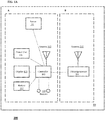
- a portable recognition device according to a preferred embodiment of the invention is generally indicated with reference numeral 100.
- device 100 represents an electronic identification document in the so-called card format or in the form of a booklet.
- Document 100 comprises a support or physical substrate indicated by reference numeral 10, upon or within which, the further components described below are incorporated.
- document 100 comprises two separate parts, or elements, indicated by A and B.
- the first element A may be defined as a biometric recognition element and is responsible for identifying the holder and enabling element B which, when in non-use mode, is electrically disconnected from the element A.
- Element B may be defined as an element for electronic storage of the holder's data and for interaction with the external means in order to perform the operation for which the document is intended.
- the two parts A and B may correspond to a physical partition of the device 100, in particular of its support 10, or be separate from a purely functional and/or activation aspect.
- the biometric recognition element A may comprise one or more biometric sensors 101, or biosensors, configured to detect one or more current biometric parameters, which we may indicate by P c , or one or more magnitudes associated therewith.
- the biometric parameter(s) Pc may represent one or more of the following identifying elements of the document holder 100: fingerprint, iris, retina, voice, facial image, hand elements, handwritten signature.
- the sensors 101 are configured to detect biometric features associated with so-called first and second level physical magnitudes, e.g., for measuring the skin resistance of a finger (with the so-called capacitive method) and the temperature differences between the ridges and valleys of the fingerprint (with the so-called thermal method).
- first and second level magnitudes can be detected by conventional sensor means.
- the biometric recognition element A further comprises communication means 102 with a remote reading or reading/writing device 301, whereby the latter is shown schematically in Fig. 2 .
- the means 102 comprise a radio-frequency (RF) circuit or antenna, which allows the element A to operate with RFID technologies.
- RF radio-frequency
- the antenna 102 powers the sensor(s) 101, utilizing the RF energy generated by an external source, in particular the above writing/reading device 301.
- the aforesaid antenna also provides communication between a controller 103, which will be introduced below, and the writing/reading device 301.
- the communication can be implemented using data encryption technologies.
- Alternative embodiments may require the communication means 102 to comprise different elements or antennas for separate implementation of the above communication features related to the remote device 301, powering the internal components of the document 100, etc.
- the biometric recognition element A preferably also comprises a power unit 104, in communication with the communication means 102 and configured for the conversion and management of RF power.
- unit 104 is configured to convert RF energy to electrical energy, and control the storage and distribution of this electrical energy to the other components of document 100.
- the biometric recognition element A comprises processing means, or a control unit, 103, in particular a controller /microprocessor, e.g., of the ASIC ( Application Specific Integrated Circuit ) chip type.
- the processing means 103 are in communication, and control the other components of the element A introduced thus far.
- the processing means 103 also incorporate means for storing at least one biometric reference parameter, which we shall indicate by P R , of the document holder 100 according to modalities, which will be illustrated below.
- element B for electronic storage of the holder's data comprises a processor or a microprocessor 201, or other means of processing, storage and/or communication configured to interact with device 301.
- microprocessor 201 is configured for storing the holder's personal data and/or access keys for interaction with the device 301, depending on the intended use of document 100.
- Microprocessor 201 communicates with the processing means 103 and is particularly configured to be activated by the latter. In the present example, this activation involves sharing the antenna 102 for power-supply purposes, as well as preferably bidirectional communication between the devices 100 and 301.
- element B furthermore comprises a dedicated antenna 202 for the microprocessor 201.
- element A also comprises a battery 107, a solar panel and/or a separate energy source for powering at least the processing means 103.
- the device 100 may include a display 105, particularly configured to provide information on the status of the device 100 or of an associated identification procedure.
- the device 100 may include input means 106, in particular one or more (push)buttons allowing an operator to perform selections.
- the display 105 may provide information related to the authentication outcome or a particular activity carried out by the device 100 by possibly interacting with the buttons 106.
- buttons 106 may interact with the other components of the device 100, typically by the means 103, to provide commands related to the activities carried out by the device 100. For example, these may activate the visualization of information via display 105.
- Fig. 2 shows an instance of interaction, in particular contactless interaction, between the device 100 and the above reading device 301.
- the device 301 may indeed be a reading and/or writing device, and/or a power supply device.
- the device 301 is configured for:
- the device 100 is configured to operate with biometric parameters consisting of two of the cardholder's biometric imprints, in particular a fingerprint detected by two different methodologies (e.g., the capacitive method and the thermal method).
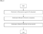
- an initialization procedure for each of the three elements of the document is provided at the same time as the document is issued.
- the three initialization procedures, relating to the physical support 10, the biometric recognition element A, and the element for electronically storing holder B's data, respectively, can be performed sequentially, simultaneously, or in no particular order. These initialization procedures are primarily intended to associate the document 100 with its owner.
- the initialization of the physical support 10 provides personalization of the holder's information, e.g., applied in graphical form by way of printing, in particular thermographic printing, laser engraving, embedded colors, etc.
- the initialization of element A requires obtaining a sampling of each of the holder's biometric fingerprints, i.e., by using a dedicated acquisition device [1].
- This enrollment phase may be done, e.g., by using the four steps explained below.
- element B an electronic storage device
- the initialization of element B is done by storing the holder's data in the nonvolatile memory of the microprocessor 201, along with all the information needed for the document 100 to function.
- the three initialization phases explained above may be performed simultaneously, or at separate times.
- document 100 is ready to use.
- a preferred procedure for use in an identification process is explained below with reference to Fig. 4 .
- Part A of the device 100 obtains the required power through the power unit 104, as soon as the said device 100 and, in particular, its antenna 102 is placed in proximity to the device 301, which generates an RF field.
- the sensor(s) 101 [when] powered, are activated and ready for biometric detection. Alternatively, the energy may be supplied by the battery 107, if present.
- the holder proceeds with the acquisition of his/her biometric imprints using the sensor 101 of the device 100.
- the newly detected imprints are subjected to preprocessing and digitized, and constitute the Fresh Templates (one for each type of imprint) or current biometric parameters P C .
- the Fresh Templates are stored in the memory of the processing device 103 and made available for subsequent identification activity.
- a similarity search algorithm (which we may define as template matching ) [7] a comparison is made for each type of imprint between the Fresh Template Pc and the Reference Template P R , whereupon a simulation index S i is determined, which we may also define as a global score or match score, and which indicates the overall similarity.
- the simulation index S I is compared with a pre-fixed threshold T S . If the similarity index S I for each type of imprint is greater than [the value of] the relevant preset threshold T S , the authentication is considered to have successfully completed. [The value of] This threshold T S is established such as to limit the rate of false rejections or "false negatives" and to zero out false acceptances or "false positives.”
- the processing means 103 activate the operation of the antenna 102, including microprocessor 201, which is otherwise disabled with respect to the latter.
- the antenna 102 powers the microprocessor 201 of element B of the device 100, whereupon communication with the reading device 301 can start.
- Document 100 may therefore be used according to its purpose.
- the document 100 is removed from the device 301 and the functionality [operation] of the antenna 102 returns to its initial disabled state.
- the processor 201 data are no longer available in any way, until further use.
- a diachronic process can always be activated inside the device for possible updating the Reference Template P R . This process will be described below.
- the holder's biometric elements may undergo an aging process during the useful life of document 100.
- a static Reference Template P R does not take these variations into account and, over time, may no longer fully represent [ ⁇ reflect] the document holder 100. Consequently, over time, this could result in errors during the document holder 100 recognition phase and affect its utilization.
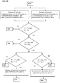
- the diachronic process may be activated each time the user is positively identified, and follows the main steps described below.
- the Fresh Template P C for each of the detected biometric parameters is considered reliable for the diachronic process, only if the comparison with the relevant Reference Template P R generates a similarity index exceeding a second prefixed threshold T Sbis , which is generally higher than the T S threshold used to identify the holder ( Fig. 5A ).
- This threshold may be chosen sufficiently high so as to exclude “false negatives,” i.e., false acceptances, and sufficiently low to allow for the variations of the detected biometric characteristics to be identified.
- updating the Reference Template P R is done only if the reliability of at least one of the Fresh Templates P C is verified, i.e., if at least one of the templates exceeds the relevant threshold T Sbis and all the others have exceeded the threshold T S .
- Updating the Reference Template (s) may be done by the processing means 103 using algorithms selected according to the types of applied biometric imprints.
- algorithms may be, e.g., of the following type[s]: "Random replacement,” i.e., random replacement of one of the "Templates,” constituting the Reference Template P R , with the Fresh Template P C ; "FIFO replacement,” whereby the older "Template” is replaced, constituting the Reference Template P R ; "NAIVE replacement,” in which the Fresh Template Pc replaces the most similar one in the Reference Template P R [7] [8] [9].
- Alternative embodiments may require that the storage of the current PC parameter(s) and/or its/their comparison with the reference parameter(s) P R be performed at the level of a device separate from the document 100, possibly a remote device or the same device 301, as described above, rather than using components that are incorporated into document 100.
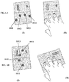
- Figs. 6A to 6D refer to alternative embodiments of the recognition document considered thus far, which will be described below [but] only in relation to the additional features and what has been described thus far.
- the recognition document is configured to detect multiple biometric parameters, e.g., a plurality of the holder's fingerprints, to make it possible for said document to interact with a remote reading device.
- Image (I) of Figs. 6A and 6B show an electronic identification document in the form of a booklet, e.g., a passport.
- the document carries four biosensors 1011-1014 arranged at a back cover of the booklet.
- the biosensors are positioned on outlet areas of the said document at the time of automatic authentication (e.g., at an electronic gate).
- the document including in image (II) illustrating its methods of use, is shown in an open configuration, which allows for automatic reading of one of its "Machine Readable Zones" associated with an internal data page, at a border-crossing point.
- the document is held firmly against a reading device, corresponding to the remote device introduced above, and at the fingertips of the hand.
- the four biosensors 1011-1014 positioned at the fingertips acquire the fingerprints that authenticate the document holder in order to enable the verification operation, i.e., interaction with the reading device.
- Images (I) and (II) of Fig. 6C shows an electronic identification document in the form of a card, e.g., an ID card or a driver's license.
- the document has two fingerprint detectors 1015 and 1016, one for each opposing main surface F1 and F2 of the card.
- the document can be effectively held between the thumb and index finger, when performing authentication of the holder as depicted in image (III), i.e., when interacting with a remote reading device.
- Image (I) of Fig. 6C shows an alternative electronic identification document in the form of a card, e.g., an ID card or a driver's license.
- the document is configured with a fingerprint detector 1017 and a signature detector 1018, arranged such as to enable the authentication operation.
- the holder is able to digitally sign the document with one hand while firmly holding the card with the other hand's index finger.
Description
- The present invention relates to a portable identification [lit. recognition] device, specifically an electronic ID card, which may be used in any situation, which requires accurate identification of the holder. The document may, e.g., be in the form of a booklet or a card, and is preferably of a type conforming to the ICAO 9303 standard (ISO 7810: 2003).
- The recognition device according to the invention is of a type suitable for memorizing one or more biometric features of the holder, and advantageously comprises one or more sensors for detecting biometric data.
- Numerous solutions relative to such a document are available on the market, e.g., in the form of a "card," which stores the holder's biometric identification data. The recognition process associated with these documents is based on comparing data stored with a biometric element and detected at the time of use or contained in a separate memory, e.g., a remote database. If this comparison matches up, the authentication process successfully terminates and the activity associated with the use of the document, e.g., a credit-card-based financial transaction, may be completed.
- The document
WO200384124A1 -
WO9913434A1 -
WO2010/022129 discloses a system comprising a transaction card having a biometric sensor and a terminal configured to read transaction information. -
EP1326196 discloses a card configured for a fingerprint authentication. If the verification gives a positive result, the card transmits an enabling signal to a security check-point. -
US6325285 relates to a card provided with a processor, a memory and a fingerprint reader. - The prior-art documents referred to above and the associated identification/authentication processes have some important disadvantages.
- Primarily, their reliability is plagued problems related to "aging" (deterioration), which all biometric elements are subject to. In fact, the authentication process may fail, even when faced with the actual document holder, as the biometric features of such person undergo variation with time. Such variations over time are minor for some biometric features, such as, e.g., fingerprints, the iris and retina, whereas other features, such as the voice, face, hand elements and handwritten signatures may vary considerable. In general, the probability of a failure to identify the actual document holder depends, apart from the sophistication of the technology used, on the selected biometric feature, in particular, its high or low variability, as mentioned above, and the time elapsed since the initialization and issuance of the document.
- A further disadvantage is that a great many prior-art document configurations are subject to tampering by malicious software, e.g., so-called "backdoors," installed without the holder's knowledge and apt to allow uncontrolled access to the data contained in the document and its fraudulent use. Likewise, some known configurations lend themselves to tampering due to false biometric features that are artificially reproduced, e.g., by cloning.
- Furthermore, the prior-art identification documents require fairly complex authentication processes.
- Besides, the processes put in place by such prior-art documents are open to improvement as regards their ability to identify the holder and reducing the number of false identifications [lit. recognitions], or non-identifications.
- What's more, the prior-art devices are configured to comprise a limited number of components, generally relying, e.g., on external sensors for detecting one or more of the subject's biometric parameters.
- Thus, the technical problem posed and solved by the present invention is to provide a portable recognition device, in particular an electronic identification document, which allows you to remove one or more of the aforementioned disadvantages of the prior art.
- This problem is solved by a recognition device according to
claim 1. - The preferred features of the present invention represent the subject matter of the dependent claims.
- In this context, the term "electronic document" should be understood in its broadest sense to include any portable document, e.g., in the form of a card or booklet, preferably conforming to the ICAO 9303/ISO 7810:2003 standard, which carries the subject's identification data and comprises electronic operation means.
- Likewise, the terms "identification," "recognition" or similar words are meant to signify any authentication process prior to enabling additional features or activities, regardless of how such enabling occurs.
- Moreover, terms such as "biometric data" or "biometric parameters" refer to any magnitude related to or associated with the identification of the document holder, in particular fingerprints, ocular or somatic features, handwritten signature, or the like.
- Likewise, the term "sensors" or similar expressions refer to any detection and/or transduction means.
- The recognition document and the inventive system require that one or more biometric reference parameters of the holder, which we may also define as models or templates, be stored in the document itself during its initialization phase. Thus, the invention provides a diachronic [or: chronologic] process for updating these biometric reference features, and makes it possible to efficiently prevent incidents of "aging" of the subject's biometric profiles, thereby ensuring the proper functioning of the document throughout its useful life.
- The identification document is preferably configured to store two different biometric parameters by using a detection feature incorporated in a single sensor or separate sensors. This parametric duality minimizes the risk of false biometric features being used successfully. Furthermore, it is possible - even with the said sensor, transducer or detector - to determine two correlated biometric magnitudes, e.g., digital skin resistance (by way of the so-called capacitive method) and differences in temperature between the ridges and valleys of the fingerprint (by way of the so-called thermal method). This dual or in any case multiple-parameter detection makes possible an authentication process and/or cross-updating of the said parameters.
- The identification document furthermore includes a data protection system based on sectioning said document into two parts, electrically separated in the non-use modes, one holding the biometric parameter(s) and the other, various identifying or enabling data of the subject for interaction with a reading device. Advantageously, the first part enables the operation of the second by means of a "disconnector" element, which, e.g., activates or shares a radio-frequency antenna, but only when the biometric identification process has successfully completed.
- The configuration of the recognition device and the system, which is the subject matter of the present invention, is therefore such that if the said device is used by a person other than the holder, it will result in a failure to recognize the biometric features. Consequently, the part of the recognition device configured to interact with a remote reader will remain physically isolated and it will therefore be impossible to use the device for the activity for which it was intended. This characteristic has proven particularly advantageous, as it makes impossible to introduce malicious software into the document, and allowing it to run there, including in the holder's absence. Also, this particular configuration prevents unauthorized access to the data stored in the document.
- Other advantages, characteristics and application methods of the present invention will become apparent from the following detailed description of some of its embodiments, presented by way of non-limiting examples.
- Reference will be made to the figures of the accompanying drawings, in which:
- ▪
Fig. 1 shows a schematic diagram of a preferred embodiment of an identification document according to the present invention; - ▪
Fig. 1A shows a schematic diagram of an alternative embodiment of the identification document inFig. 1 ; - ▪
Fig. 2 shows a schematic diagram relating to contactless interaction between the document inFig. 1 or1A and a reading and/or writing device; - ▪
Fig. 3 shows a schematic flow diagram of a preferred initialization sequence of the document inFig. 1 or1A ; - ▪
Fig. 3A shows a schematic flow diagram related to a preferred initialization mode of an external support of the document inFig. 1 or1A ; - ▪
Fig. 3B shows a schematic flow diagram related to a preferred initialization mode of a first part of the document inFig. 1 or1A ; - ▪
Fig. 3C shows a schematic flow diagram related to a preferred initialization mode of a second part of the document inFig. 1 or1A ; - ▪
Fig. 4 shows a schematic flow diagram related to a preferred mode of operation of the document inFig. 1 or1A ; - ▪
Fig. 5A shows a schematic flow diagram related to preferred embodiments of a diachronic process associated with the document ofFig. 1 or1A ; - ▪
Fig. 5B shows a schematic flow diagram related to preferred embodiments of a diachronic process performed by way of mutual certification;- ▪
Figs. 6A to 6D are each a schematic representation of a corresponding alternative embodiment of the document inFig. 1 , with specific reference to the positioning of biosensors, i.e., sensors for detecting one or more biometric parameters. In particular, in image (I),Figs. 6A and 6B represent a front view of a recognition document in booklet format and, in image (II), the same document during an identification process, the said figures referring to two different preferred configurations;Fig. 6C , in images (I) and (II), shows plan views of two corresponding opposing main surfaces of a recognition document in card format and, in image (III), the same document during an identification process;Fig. 6D , in image (I), shows a plan view of an identification document in card format and, in image (II), the same document during an identification process.
- ▪
- With initial reference to
Fig. 1 , a portable recognition device according to a preferred embodiment of the invention is generally indicated withreference numeral 100. In the present example,device 100 represents an electronic identification document in the so-called card format or in the form of a booklet. -
Document 100 comprises a support or physical substrate indicated byreference numeral 10, upon or within which, the further components described below are incorporated. - Preferably,
document 100 comprises two separate parts, or elements, indicated by A and B. In particular, the first element A may be defined as a biometric recognition element and is responsible for identifying the holder and enabling element B which, when in non-use mode, is electrically disconnected from the element A. - Element B may be defined as an element for electronic storage of the holder's data and for interaction with the external means in order to perform the operation for which the document is intended.
- It is obvious that the two parts A and B may correspond to a physical partition of the
device 100, in particular of itssupport 10, or be separate from a purely functional and/or activation aspect. - The biometric recognition element A may comprise one or more
biometric sensors 101, or biosensors, configured to detect one or more current biometric parameters, which we may indicate by Pc, or one or more magnitudes associated therewith. In the present example, the biometric parameter(s) Pc may represent one or more of the following identifying elements of the document holder 100: fingerprint, iris, retina, voice, facial image, hand elements, handwritten signature. - In a particularly preferred embodiment, the
sensors 101 are configured to detect biometric features associated with so-called first and second level physical magnitudes, e.g., for measuring the skin resistance of a finger (with the so-called capacitive method) and the temperature differences between the ridges and valleys of the fingerprint (with the so-called thermal method). These first and second level magnitudes can be detected by conventional sensor means. - In the present example, the biometric recognition element A further comprises communication means 102 with a remote reading or reading/
writing device 301, whereby the latter is shown schematically inFig. 2 . In the present example, themeans 102 comprise a radio-frequency (RF) circuit or antenna, which allows the element A to operate with RFID technologies. - In the present embodiment, the
antenna 102 powers the sensor(s) 101, utilizing the RF energy generated by an external source, in particular the above writing/reading device 301. - The aforesaid antenna also provides communication between a
controller 103, which will be introduced below, and the writing/reading device 301. The communication can be implemented using data encryption technologies. - Alternative embodiments may require the communication means 102 to comprise different elements or antennas for separate implementation of the above communication features related to the
remote device 301, powering the internal components of thedocument 100, etc. - The biometric recognition element A preferably also comprises a
power unit 104, in communication with the communication means 102 and configured for the conversion and management of RF power. In particular,unit 104 is configured to convert RF energy to electrical energy, and control the storage and distribution of this electrical energy to the other components ofdocument 100. - Hence, the biometric recognition element A comprises processing means, or a control unit, 103, in particular a controller/microprocessor, e.g., of the ASIC (Application Specific Integrated Circuit) chip type. The processing means 103 are in communication, and control the other components of the element A introduced thus far. In the present example, the processing means 103 also incorporate means for storing at least one biometric reference parameter, which we shall indicate by PR, of the
document holder 100 according to modalities, which will be illustrated below. - In the present embodiment, element B for electronic storage of the holder's data comprises a processor or a
microprocessor 201, or other means of processing, storage and/or communication configured to interact withdevice 301. - In the current example,
microprocessor 201 is configured for storing the holder's personal data and/or access keys for interaction with thedevice 301, depending on the intended use ofdocument 100.Microprocessor 201 communicates with the processing means 103 and is particularly configured to be activated by the latter. In the present example, this activation involves sharing theantenna 102 for power-supply purposes, as well as preferably bidirectional communication between thedevices - With reference to
Fig. 1A , in an alternative embodiment, element B furthermore comprises adedicated antenna 202 for themicroprocessor 201. - In addition, based on a further alternative embodiment, also shown in
Fig. 1A , element A also comprises abattery 107, a solar panel and/or a separate energy source for powering at least the processing means 103. - Furthermore, according to possible alternative embodiments, the
device 100, for example, in correspondence with the element A, may include adisplay 105, particularly configured to provide information on the status of thedevice 100 or of an associated identification procedure. - Similarly, the
device 100 may include input means 106, in particular one or more (push)buttons allowing an operator to perform selections. - In a preferred operating mode, the
display 105 may provide information related to the authentication outcome or a particular activity carried out by thedevice 100 by possibly interacting with thebuttons 106. - The
buttons 106 may interact with the other components of thedevice 100, typically by themeans 103, to provide commands related to the activities carried out by thedevice 100. For example, these may activate the visualization of information viadisplay 105. -
Fig. 2 shows an instance of interaction, in particular contactless interaction, between thedevice 100 and theabove reading device 301. - In alternative embodiments, the
device 301 may indeed be a reading and/or writing device, and/or a power supply device. In the current example, thedevice 301 is configured for: - ▪ Providing radiofrequency energy to the
antenna 102 in order to activate the biosensor(s) 101 of the element A by generating an RF field; - ▪ Establishing a connection of the element B with the microprocessor 201 (e.g., by two-way communication) in order to exchange data/information;
- ▪ Performing possible further read/write operations on the memory of the processing means 103 and/or additional storage means provided in the
microprocessor 201. - Preferred modes of operation of the
device 100 will now be described with reference to preliminary initialization procedures, as well as the operation of thedevice 100 in an identification process. In the following example, thedevice 100 is configured to operate with biometric parameters consisting of two of the cardholder's biometric imprints, in particular a fingerprint detected by two different methodologies (e.g., the capacitive method and the thermal method). - With reference to
Fig. 3 , an initialization procedure for each of the three elements of the document is provided at the same time as the document is issued. The three initialization procedures, relating to thephysical support 10, the biometric recognition element A, and the element for electronically storing holder B's data, respectively, can be performed sequentially, simultaneously, or in no particular order. These initialization procedures are primarily intended to associate thedocument 100 with its owner. - In the current example and with reference to
Fig. 3A , the initialization of thephysical support 10 provides personalization of the holder's information, e.g., applied in graphical form by way of printing, in particular thermographic printing, laser engraving, embedded colors, etc. - With reference to
Fig. 3B , during the user registration or enrollment phase, the initialization of element A (a biometric component) requires obtaining a sampling of each of the holder's biometric fingerprints, i.e., by using a dedicated acquisition device [1]. - This enrollment phase may be done, e.g., by using the four steps explained below.
- (i) Data acquisition - using the sensor(s) 101 of a dedicated detection apparatus, a sufficient sampling is acquired for each biometric fingerprint of interest to constitute a statistically valid data set [1].
- (ii) Extraction of features - each acquired detection is subjected to preprocessing treatment using:
- An "enhancement-quality" algorithm [2] in order to enhance sample quality and reduce noise;
- a "features extraction" algorithm [3] for the extraction of the most significant features ("feature set") of the discriminating samples for the recognition and transformation of these features into a digital representation (template), e.g., the most significant features are extracted from the fingerprints, i.e., the discontinuities of the ridge/valley structure ("minutiae"), and digitally represented as a binary code.
- (iii) Definition of the "Reference Templates", i.e., the biometric reference parameter(s) PR - For each biometric parameter, the set of "Templates" produced by the detections will constitute the "Reference Template." The "Reference Templates" will be used as comparison elements during the holder identification phase.
- (iv) Storing the "Reference Template(s)" - The "Reference Templates" are stored in an encrypted fashion in the non-volatile memory of the processing means 103 using encryption algorithms [4] [5] [6] (e.g., standard 192 or 256-bit AES symmetric encryption algorithms with SHA-256 hash function or 112-bit 3DES with SHA-1 hash function).
- With reference to
Fig. 3C , the initialization of element B (an electronic storage device) is done by storing the holder's data in the nonvolatile memory of themicroprocessor 201, along with all the information needed for thedocument 100 to function. - As mentioned above, the three initialization phases explained above may be performed simultaneously, or at separate times.
- Following initialization,
document 100 is ready to use. A preferred procedure for use in an identification process is explained below with reference toFig. 4 . - Part A of the
device 100 obtains the required power through thepower unit 104, as soon as the saiddevice 100 and, in particular, itsantenna 102 is placed in proximity to thedevice 301, which generates an RF field. The sensor(s) 101, [when] powered, are activated and ready for biometric detection. Alternatively, the energy may be supplied by thebattery 107, if present. - The holder proceeds with the acquisition of his/her biometric imprints using the
sensor 101 of thedevice 100. The newly detected imprints are subjected to preprocessing and digitized, and constitute the Fresh Templates (one for each type of imprint) or current biometric parameters PC. The Fresh Templates are stored in the memory of theprocessing device 103 and made available for subsequent identification activity. - Through a similarity search algorithm (which we may define as template matching) [7], a comparison is made for each type of imprint between the Fresh Template Pc and the Reference Template PR, whereupon a simulation index Si is determined, which we may also define as a global score or match score, and which indicates the overall similarity.
- As the biometric systems generally do not provide a 100% match, the simulation index SI is compared with a pre-fixed threshold TS. If the similarity index SI for each type of imprint is greater than [the value of] the relevant preset threshold TS, the authentication is considered to have successfully completed. [The value of] This threshold TS is established such as to limit the rate of false rejections or "false negatives" and to zero out false acceptances or "false positives."
- In the event of positive authentication, the processing means 103 activate the operation of the
antenna 102, includingmicroprocessor 201, which is otherwise disabled with respect to the latter. Theantenna 102 powers themicroprocessor 201 of element B of thedevice 100, whereupon communication with thereading device 301 can start.Document 100 may therefore be used according to its purpose. - When the application activity is completed, the
document 100 is removed from thedevice 301 and the functionality [operation] of theantenna 102 returns to its initial disabled state. Thus, theprocessor 201 data are no longer available in any way, until further use. - Moreover, in the event of positive authentication, a diachronic process can always be activated inside the device for possible updating the Reference Template PR. This process will be described below.
- In the event of negative authentication, i.e., if the similarity index SI is lower than the prefixed value TS for at least one of the detected biometric parameters, authentication is considered not to have successfully completed and, therefore, the document cannot be used for its [intended] purpose, since the part, part B [typo], of the document (processor 201) is inaccessible. The user must remove the
document 100 from thedevice 301 in order to disable the saiddocument 100, and possibly restart the authentication process. - The diachronic process for updating the Reference Template PR is described below.
- As mentioned above, the holder's biometric elements may undergo an aging process during the useful life of
document 100. A static Reference Template PR does not take these variations into account and, over time, may no longer fully represent [∼reflect] thedocument holder 100. Consequently, over time, this could result in errors during thedocument holder 100 recognition phase and affect its utilization. - To ensure that the Reference Template PR continues to be fully representative of the user, the use of algorithms that are able to continuously update it, while using the document, is advantageous.
- The diachronic process may be activated each time the user is positively identified, and follows the main steps described below.
- The Fresh Template PC for each of the detected biometric parameters is considered reliable for the diachronic process, only if the comparison with the relevant Reference Template PR generates a similarity index exceeding a second prefixed threshold TSbis, which is generally higher than the TS threshold used to identify the holder (
Fig. 5A ). This threshold may be chosen sufficiently high so as to exclude "false negatives," i.e., false acceptances, and sufficiently low to allow for the variations of the detected biometric characteristics to be identified. - If
document 100 requires two or more biometric detections, updating the Reference Template PR is done only if the reliability of at least one of the Fresh Templates PC is verified, i.e., if at least one of the templates exceeds the relevant threshold TSbis and all the others have exceeded the threshold TS. Below follow some useful criteria by way of some non-limiting examples that may be used based on the relatively high variability of the applied biometric imprints, the desired degree of security to be achieved, and the specific circumstances. - (i) Independent updating of each Reference Template PR corresponding to the Fresh Template PC, whose reliability has been verified.
- (ii) Updating through mutual certification, i.e., if the reliability of the first Fresh Template PC is verified, [and] the Reference Template PR is updated relative to the other biometric imprint(s), and vice versa, as shown in
Fig. 5B . - (iii) Updating all the Reference Templates PR [is done] only if the reliability of all the Fresh Templates PC are verified.
- (iv) Updating the Reference Template PR [is done] only if the reliability of the Fresh Templates PC have been verified and further boundary conditions, possibly of a statistical kind, are simultaneously verified.
- Updating the Reference Template(s) may be done by the processing means 103 using algorithms selected according to the types of applied biometric imprints. Such algorithms may be, e.g., of the following type[s]: "Random replacement," i.e., random replacement of one of the "Templates," constituting the Reference Template PR, with the Fresh Template PC; "FIFO replacement," whereby the older "Template" is replaced, constituting the Reference Template PR; "NAIVE replacement," in which the Fresh Template Pc replaces the most similar one in the Reference Template PR [7] [8] [9].
- Alternative embodiments may require that the storage of the current PC parameter(s) and/or its/their comparison with the reference parameter(s) PR be performed at the level of a device separate from the
document 100, possibly a remote device or thesame device 301, as described above, rather than using components that are incorporated intodocument 100. -
Figs. 6A to 6D refer to alternative embodiments of the recognition document considered thus far, which will be described below [but] only in relation to the additional features and what has been described thus far. In all the described alternative embodiments, the recognition document is configured to detect multiple biometric parameters, e.g., a plurality of the holder's fingerprints, to make it possible for said document to interact with a remote reading device. - Image (I) of
Figs. 6A and 6B show an electronic identification document in the form of a booklet, e.g., a passport. As sensor means, the document carries four biosensors 1011-1014 arranged at a back cover of the booklet. In particular, the biosensors are positioned on outlet areas of the said document at the time of automatic authentication (e.g., at an electronic gate). - The document, including in image (II) illustrating its methods of use, is shown in an open configuration, which allows for automatic reading of one of its "Machine Readable Zones" associated with an internal data page, at a border-crossing point. To this end, the document is held firmly against a reading device, corresponding to the remote device introduced above, and at the fingertips of the hand. The four biosensors 1011-1014 positioned at the fingertips acquire the fingerprints that authenticate the document holder in order to enable the verification operation, i.e., interaction with the reading device.
- Images (I) and (II) of
Fig. 6C shows an electronic identification document in the form of a card, e.g., an ID card or a driver's license. As sensor means, the document has twofingerprint detectors - Image (I) of
Fig. 6C shows an alternative electronic identification document in the form of a card, e.g., an ID card or a driver's license. The document is configured with afingerprint detector 1017 and asignature detector 1018, arranged such as to enable the authentication operation. In fact, the holder is able to digitally sign the document with one hand while firmly holding the card with the other hand's index finger. - The present invention has thus far been described with reference to preferred embodiments. It is to be understood that other embodiments may exist and which belong to the same inventive core, as defined by the scope of the claims set forth below.
-
- [1] D Maltoni, D Maio, AK Jain, and S Prabhakar, Handbook of Fingerprint: Recognition (2nd Edition), Springer, 2009
- [2] L Hong, Y Wan, AK Jain, "Fingerprint Image Enhancement Algorithms and Performance Evaluation", IEEE Transactions on Pattern Analysis: and Machine Intelligence, vol. 20, no. 8, pp. 777-789, 1998.
- [3] NK Ratha, SY Chen, AK Jain, "Adaptive Flow Orientation-based Feature Extraction in Fingerprint Images", Pattern Recognition, vol. 28, No. 11, pp. 1657-1672, 1995.
- [4] ICAO 9303 2015
- [5] Advanced Encryption Standard, searchsecurity.techtarget.com
- [6] Crittografia a chiave simmetrica [Symmetric Key Cryptography], cs.cornell.edu.
- [7] Kumar, D Ashok, and T Ummal Sariba Begum. "A Comparative Study on Fingerprint Matching Algorithms for EVM." Journal of Computer Sciences and Applications 1.4 (2013): 55-60.
- [8] T Scheidat, A Makrushin, and C Vielhauer, Automatic Template Update Strategies for Biometrics, Tech. Rep., Otto-von-Guericke University Magdeburg, 2007. [cired ar p. 48, 53]
- [9] Strategies for Biometrics, Tech. Rep., Otto-von-Guericke University Magdeburg,2007.
Claims (12)
- An electronic identification document (100) in the form of a card or booklet, comprising :- a physical support (10);- a control unit (103) incorporating means for storing at least one reference biometric parameter (PR) of a holder of the electronic identification document (100);- sensor means (101), configured to detect at least one current biometric parameter (PC);- communication means (102);- a power unit (104);- a processor (201) configured to interact with a remote device (301), read data from, write data on and/or power said electronic identification document (100) and store holder's personal data for interaction with the remote device (301);wherein the control unit is (103) programmed to:a) comparing said biometric reference parameter (PR) with said current biometric parameter (PC) and calculating a similarity index (IS);b) comparing said similarity index (IS) with a first predetermined threshold (TS), and, in case said similarity index (IS) is greater than said first predetermined threshold (TS), enabling said processor (201) to an interaction with the remote device (301);
and it is characterized in that:c) in the event said similarity index (IS) is greater than a second predetermined threshold (TSbis) higher than said first predetermined threshold (TS), updating said reference biometric parameter (PR) with said current biometric parameter (PC) in said storage means;which electronic identification document (100) presents a partition in a first (A) and a second (B) part, wherein said first part (A) bears said sensor means (101), said communication means (102), said control unit (103) and said power unit (104) and said second part (B) bears said processor (201),
wherein said second part (B) bears additional storage means of identification data of the holder of the document itself and/or access keys for interaction with the remote device (301),
and wherein said control unit (103) is configured to allow an enabling of said communication means (102) between said first (A) and said second (B) part and/or between said second part (B) and the remote device (301) in said step (b). - The electronic identification document (100) according to claim 1, wherein said communication means (102) comprises at least one radiofrequency antenna or circuit.
- The electronic identification document (100) according to claim 1 or 2, wherein said communication means (102) are configured for powering said processing means (103) and/or said sensor means (101).
- The electronic identification document (100) according to any one of the preceding claims, wherein said reference biometric parameter (PR) and said current biometric parameter (Pc) are representative of one or more of the following elements: fingerprint, iris, retina, voice, facial image, skin resistance, handwritten signature.
- The electronic identification document (100) according to any one of the preceding claims, wherein said storage means (103) is configured to store at least a pair of distinct reference biometric parameters (PR) and wherein said steps from (a) to (c) are carried out in relation to each of said reference biometric parameters (PR) and to a respective pair of current biometric parameters (Pc).
- The electronic identification document (100) according to any one of the preceding claims, wherein said sensor means comprises detecting means of two correlated current biometric parameters, for example a digital skin resistance and a temperature difference between ridges and valleys of a corresponding fingerprint.
- The electronic identification document (100) according to the preceding claim, wherein said processing means (103) is configured to execute a cross authentication of said correlated current biometric parameters.
- The electronic identification document (100) according to any one of the preceding claims, which is in the card form and wherein said sensor means (101) comprises a first (1015) and a second (1016) fingerprint detector placed at opposing sides.
- The electronic identification document (100) according to any one of the preceding claims which is in the card form and wherein said sensor means (101) comprises a fingerprint detector (1017) and a handwritten signature detector (1018), preferably placed at the same side.
- The electronic identification document (100) according to any one of the claims from 1 to 9, which is in the booklet form and wherein said sensor means (101) comprises a plurality of fingerprint detectors (1011-1014) placed at a back cover.
- An identification system, comprising:▪ an electronic identification document (100) according to any one of the preceding claims; and▪ a remote device (301), configured to read data from, write data on and/or power said electronic identification document (100).
- The identification system according to the preceding claim, wherein the remote device is configured for:▪ providing radiofrequency energy to communication means (102) of said electronic identification document (100) in order to activate enabling of said sensor means (101);▪ establishing a connection with said processor (201) in order to exchange data and/or information; and▪ performing read/write data operations on said communication means (102) and/or said control unit (103) and/or said processor (201).
Priority Applications (3)
| Application Number | Priority Date | Filing Date | Title |
|---|---|---|---|
| SI201830100T SI3388974T1 (en) | 2017-04-13 | 2018-04-09 | New identification document |
| RS20200976A RS60655B1 (en) | 2017-04-13 | 2018-04-09 | New identification document |
| HRP20201235TT HRP20201235T1 (en) | 2017-04-13 | 2020-08-06 | New identification document |
Applications Claiming Priority (1)
| Application Number | Priority Date | Filing Date | Title |
|---|---|---|---|
| IT102017000041158A IT201700041158A1 (en) | 2017-04-13 | 2017-04-13 | NEW IDENTIFICATION DOCUMENT |
Publications (2)
| Publication Number | Publication Date |
|---|---|
| EP3388974A1 EP3388974A1 (en) | 2018-10-17 |
| EP3388974B1 true EP3388974B1 (en) | 2020-05-27 |
Family
ID=60138685
Family Applications (1)
| Application Number | Title | Priority Date | Filing Date |
|---|---|---|---|
| EP18166260.2A Active EP3388974B1 (en) | 2017-04-13 | 2018-04-09 | New identification document |
Country Status (11)
| Country | Link |
|---|---|
| EP (1) | EP3388974B1 (en) |
| CY (1) | CY1123281T1 (en) |
| DK (1) | DK3388974T3 (en) |
| ES (1) | ES2809198T3 (en) |
| HR (1) | HRP20201235T1 (en) |
| HU (1) | HUE051608T2 (en) |
| IT (1) | IT201700041158A1 (en) |
| LT (1) | LT3388974T (en) |
| PT (1) | PT3388974T (en) |
| RS (1) | RS60655B1 (en) |
| SI (1) | SI3388974T1 (en) |
Family Cites Families (7)
| Publication number | Priority date | Publication date | Assignee | Title |
|---|---|---|---|---|
| US6213391B1 (en) | 1997-09-10 | 2001-04-10 | William H. Lewis | Portable system for personal identification based upon distinctive characteristics of the user |
| US6325285B1 (en) * | 1999-11-12 | 2001-12-04 | At&T Corp. | Smart card with integrated fingerprint reader |
| EP1326196B1 (en) * | 2002-01-04 | 2006-03-22 | Magnex Corporation | Fingerprint sensing smart card with on-card fingerprint comparison |
| EP1535421A4 (en) * | 2002-03-28 | 2005-09-07 | Innovation Connection Corp | Apparatus and method for transactions security using biometric identity validation and contactless smartcard. |
| EP2324445B1 (en) * | 2008-08-20 | 2019-03-20 | Xcard Holdings, LLC | Secure smart card system |
| WO2012042634A1 (en) * | 2010-09-30 | 2012-04-05 | 富士通株式会社 | Biometric authentication device, biometric authentication program and method |
| WO2012131899A1 (en) * | 2011-03-29 | 2012-10-04 | 富士通フロンテック株式会社 | Biometric authentication apparatus, biometric authentication system, and biometric authentication method |
-
2017
- 2017-04-13 IT IT102017000041158A patent/IT201700041158A1/en unknown
-
2018
- 2018-04-09 LT LTEP18166260.2T patent/LT3388974T/en unknown
- 2018-04-09 EP EP18166260.2A patent/EP3388974B1/en active Active
- 2018-04-09 DK DK18166260.2T patent/DK3388974T3/en active
- 2018-04-09 SI SI201830100T patent/SI3388974T1/en unknown
- 2018-04-09 RS RS20200976A patent/RS60655B1/en unknown
- 2018-04-09 PT PT181662602T patent/PT3388974T/en unknown
- 2018-04-09 ES ES18166260T patent/ES2809198T3/en active Active
- 2018-04-09 HU HUE18166260A patent/HUE051608T2/en unknown
-
2020
- 2020-08-06 HR HRP20201235TT patent/HRP20201235T1/en unknown
- 2020-08-26 CY CY20201100800T patent/CY1123281T1/en unknown
Non-Patent Citations (1)
| Title |
|---|
| None * |
Also Published As
| Publication number | Publication date |
|---|---|
| DK3388974T3 (en) | 2020-08-24 |
| EP3388974A1 (en) | 2018-10-17 |
| CY1123281T1 (en) | 2021-12-31 |
| SI3388974T1 (en) | 2020-10-30 |
| ES2809198T3 (en) | 2021-03-03 |
| HRP20201235T1 (en) | 2020-11-13 |
| HUE051608T2 (en) | 2021-03-01 |
| RS60655B1 (en) | 2020-09-30 |
| IT201700041158A1 (en) | 2018-10-13 |
| PT3388974T (en) | 2020-08-14 |
| LT3388974T (en) | 2020-09-10 |
Similar Documents
| Publication | Publication Date | Title |
|---|---|---|
| US10437976B2 (en) | Biometric personal data key (PDK) authentication | |
| Weaver | Biometric authentication | |
| US20060170530A1 (en) | Fingerprint-based authentication using radio frequency identification | |
| US20050188213A1 (en) | System for personal identity verification | |
| US20080172733A1 (en) | Identification and verification method and system for use in a secure workstation | |
| WO2009055303A1 (en) | Biometric secure transaction card | |
| EP2477157A1 (en) | Biometric authentication system, method and program | |
| EP3067813B1 (en) | Portable electronic device and system | |
| Wu et al. | Access control by RFID and face recognition based on neural network | |
| Okokpujie et al. | Integration of iris biometrics in automated teller machines for enhanced user authentication | |
| KR20160101249A (en) | Authentication method for portable secure authentication apparatus using fingerprint | |
| JPH11312225A (en) | Ic card with fingerprint reading and authenticating function | |
| EP3388974B1 (en) | New identification document | |
| Bhartiya et al. | Biometric authentication systems: security concerns and solutions | |
| KR100397382B1 (en) | System of smart card for fingerprinting cognition | |
| JP2007305011A (en) | Biometric authenticating device | |
| Isa et al. | The design of fingerprint biometric authentication on smart card for PULAPOT main entrance system | |
| GB2511467A (en) | Access management system and method | |
| Hussain et al. | BSC: A Novel Scheme for Providing Security using Biometric Smart Card | |
| JP2007080193A (en) | Operator authentication system and operator authentication method | |
| Uchenna et al. | Overview of technologies and fingerprint scanner used for biometric capturing | |
| Odiete et al. | An automated door control system using biometric technology | |
| Bhardwaj et al. | Match-on-Card Biometric Framework | |
| Nemade et al. | A Review Paper on Improving Security of ATM System | |
| JP2023035068A (en) | Information processing apparatus, information processing method, and information processing program |
Legal Events
| Date | Code | Title | Description |
|---|---|---|---|
| PUAI | Public reference made under article 153(3) epc to a published international application that has entered the european phase |
Free format text: ORIGINAL CODE: 0009012 |
|
| STAA | Information on the status of an ep patent application or granted ep patent |
Free format text: STATUS: THE APPLICATION HAS BEEN PUBLISHED |
|
| AK | Designated contracting states |
Kind code of ref document: A1 Designated state(s): AL AT BE BG CH CY CZ DE DK EE ES FI FR GB GR HR HU IE IS IT LI LT LU LV MC MK MT NL NO PL PT RO RS SE SI SK SM TR |
|
| AX | Request for extension of the european patent |
Extension state: BA ME |
|
| STAA | Information on the status of an ep patent application or granted ep patent |
Free format text: STATUS: REQUEST FOR EXAMINATION WAS MADE |
|
| 17P | Request for examination filed |
Effective date: 20190417 |
|
| RBV | Designated contracting states (corrected) |
Designated state(s): AL AT BE BG CH CY CZ DE DK EE ES FI FR GB GR HR HU IE IS IT LI LT LU LV MC MK MT NL NO PL PT RO RS SE SI SK SM TR |
|
| STAA | Information on the status of an ep patent application or granted ep patent |
Free format text: STATUS: EXAMINATION IS IN PROGRESS |
|
| 17Q | First examination report despatched |
Effective date: 20190829 |
|
| GRAP | Despatch of communication of intention to grant a patent |
Free format text: ORIGINAL CODE: EPIDOSNIGR1 |
|
| STAA | Information on the status of an ep patent application or granted ep patent |
Free format text: STATUS: GRANT OF PATENT IS INTENDED |
|
| RIC1 | Information provided on ipc code assigned before grant |
Ipc: G06Q 20/40 20120101ALI20200204BHEP Ipc: G06K 9/00 20060101AFI20200204BHEP Ipc: G07F 7/08 20060101ALI20200204BHEP Ipc: G06Q 20/34 20120101ALI20200204BHEP |
|
| INTG | Intention to grant announced |
Effective date: 20200224 |
|
| GRAS | Grant fee paid |
Free format text: ORIGINAL CODE: EPIDOSNIGR3 |
|
| GRAJ | Information related to disapproval of communication of intention to grant by the applicant or resumption of examination proceedings by the epo deleted |
Free format text: ORIGINAL CODE: EPIDOSDIGR1 |
|
| GRAL | Information related to payment of fee for publishing/printing deleted |
Free format text: ORIGINAL CODE: EPIDOSDIGR3 |
|
| STAA | Information on the status of an ep patent application or granted ep patent |
Free format text: STATUS: EXAMINATION IS IN PROGRESS |
|
| GRAJ | Information related to disapproval of communication of intention to grant by the applicant or resumption of examination proceedings by the epo deleted |
Free format text: ORIGINAL CODE: EPIDOSDIGR1 |
|
| GRAP | Despatch of communication of intention to grant a patent |
Free format text: ORIGINAL CODE: EPIDOSNIGR1 |
|
| GRAR | Information related to intention to grant a patent recorded |
Free format text: ORIGINAL CODE: EPIDOSNIGR71 |
|
| STAA | Information on the status of an ep patent application or granted ep patent |
Free format text: STATUS: GRANT OF PATENT IS INTENDED |
|
| GRAA | (expected) grant |
Free format text: ORIGINAL CODE: 0009210 |
|
| STAA | Information on the status of an ep patent application or granted ep patent |
Free format text: STATUS: THE PATENT HAS BEEN GRANTED |
|
| INTC | Intention to grant announced (deleted) | ||
| AK | Designated contracting states |
Kind code of ref document: B1 Designated state(s): AL AT BE BG CH CY CZ DE DK EE ES FI FR GB GR HR HU IE IS IT LI LT LU LV MC MK MT NL NO PL PT RO RS SE SI SK SM TR |
|
| INTG | Intention to grant announced |
Effective date: 20200420 |
|
| REG | Reference to a national code |
Ref country code: GB Ref legal event code: FG4D |
|
| REG | Reference to a national code |
Ref country code: CH Ref legal event code: EP |
|
| REG | Reference to a national code |
Ref country code: AT Ref legal event code: REF Ref document number: 1275301 Country of ref document: AT Kind code of ref document: T Effective date: 20200615 |
|
| REG | Reference to a national code |
Ref country code: DE Ref legal event code: R096 Ref document number: 602018004817 Country of ref document: DE |
|
| REG | Reference to a national code |
Ref country code: HR Ref legal event code: TUEP Ref document number: P20201235T Country of ref document: HR Ref country code: FI Ref legal event code: FGE |
|
| REG | Reference to a national code |
Ref country code: PT Ref legal event code: SC4A Ref document number: 3388974 Country of ref document: PT Date of ref document: 20200814 Kind code of ref document: T Free format text: AVAILABILITY OF NATIONAL TRANSLATION Effective date: 20200731 Ref country code: CH Ref legal event code: NV Representative=s name: PATENTANWAELTE SCHAAD, BALASS, MENZL AND PARTN, CH |
|
| REG | Reference to a national code |
Ref country code: NL Ref legal event code: FP |
|
| REG | Reference to a national code |
Ref country code: DK Ref legal event code: T3 Effective date: 20200818 |
|
| REG | Reference to a national code |
Ref country code: SE Ref legal event code: TRGR |
|
| REG | Reference to a national code |
Ref country code: NO Ref legal event code: T2 Effective date: 20200527 |
|
| REG | Reference to a national code |
Ref country code: GR Ref legal event code: EP Ref document number: 20200402418 Country of ref document: GR Effective date: 20201014 |
|
| REG | Reference to a national code |
Ref country code: HR Ref legal event code: T1PR Ref document number: P20201235 Country of ref document: HR |
|
| REG | Reference to a national code |
Ref country code: EE Ref legal event code: FG4A Ref document number: E019828 Country of ref document: EE Effective date: 20200821 |
|
| REG | Reference to a national code |
Ref country code: SK Ref legal event code: T3 Ref document number: E 35445 Country of ref document: SK |
|
| REG | Reference to a national code |
Ref country code: AT Ref legal event code: UEP Ref document number: 1275301 Country of ref document: AT Kind code of ref document: T Effective date: 20200527 |
|
| REG | Reference to a national code |
Ref country code: HU Ref legal event code: AG4A Ref document number: E051608 Country of ref document: HU |
|
| REG | Reference to a national code |
Ref country code: DE Ref legal event code: R097 Ref document number: 602018004817 Country of ref document: DE |
|
| REG | Reference to a national code |
Ref country code: ES Ref legal event code: FG2A Ref document number: 2809198 Country of ref document: ES Kind code of ref document: T3 Effective date: 20210303 |
|
| PLBE | No opposition filed within time limit |
Free format text: ORIGINAL CODE: 0009261 |
|
| STAA | Information on the status of an ep patent application or granted ep patent |
Free format text: STATUS: NO OPPOSITION FILED WITHIN TIME LIMIT |
|
| REG | Reference to a national code |
Ref country code: HR Ref legal event code: ODRP Ref document number: P20201235 Country of ref document: HR Payment date: 20210406 Year of fee payment: 4 |
|
| 26N | No opposition filed |
Effective date: 20210302 |
|
| REG | Reference to a national code |
Ref country code: DE Ref legal event code: R079 Ref document number: 602018004817 Country of ref document: DE Free format text: PREVIOUS MAIN CLASS: G06K0009000000 Ipc: G06V0010000000 |
|
| REG | Reference to a national code |
Ref country code: HR Ref legal event code: ODRP Ref document number: P20201235 Country of ref document: HR Payment date: 20220711 Year of fee payment: 5 |
|
| PGFP | Annual fee paid to national office [announced via postgrant information from national office to epo] |
Ref country code: MK Payment date: 20220330 Year of fee payment: 5 |
|
| REG | Reference to a national code |
Ref country code: HR Ref legal event code: ODRP Ref document number: P20201235 Country of ref document: HR Payment date: 20230327 Year of fee payment: 6 |
|
| PGFP | Annual fee paid to national office [announced via postgrant information from national office to epo] |
Ref country code: RO Payment date: 20230331 Year of fee payment: 6 Ref country code: MC Payment date: 20230327 Year of fee payment: 6 Ref country code: LT Payment date: 20230324 Year of fee payment: 6 Ref country code: CZ Payment date: 20230322 Year of fee payment: 6 |
|
| PGFP | Annual fee paid to national office [announced via postgrant information from national office to epo] |
Ref country code: SK Payment date: 20230322 Year of fee payment: 6 Ref country code: RS Payment date: 20230322 Year of fee payment: 6 Ref country code: PT Payment date: 20230321 Year of fee payment: 6 Ref country code: HR Payment date: 20230327 Year of fee payment: 6 |
|
| PGFP | Annual fee paid to national office [announced via postgrant information from national office to epo] |
Ref country code: NL Payment date: 20230422 Year of fee payment: 6 Ref country code: LU Payment date: 20230418 Year of fee payment: 6 |
|
| PGFP | Annual fee paid to national office [announced via postgrant information from national office to epo] |
Ref country code: SM Payment date: 20230419 Year of fee payment: 6 Ref country code: NO Payment date: 20230419 Year of fee payment: 6 Ref country code: IT Payment date: 20230428 Year of fee payment: 6 Ref country code: IE Payment date: 20230419 Year of fee payment: 6 Ref country code: FR Payment date: 20230417 Year of fee payment: 6 Ref country code: ES Payment date: 20230503 Year of fee payment: 6 Ref country code: EE Payment date: 20230413 Year of fee payment: 6 Ref country code: DK Payment date: 20230419 Year of fee payment: 6 Ref country code: DE Payment date: 20230420 Year of fee payment: 6 Ref country code: CY Payment date: 20230331 Year of fee payment: 6 Ref country code: CH Payment date: 20230502 Year of fee payment: 6 Ref country code: BG Payment date: 20230428 Year of fee payment: 6 |
|
| PGFP | Annual fee paid to national office [announced via postgrant information from national office to epo] |
Ref country code: TR Payment date: 20230406 Year of fee payment: 6 Ref country code: SI Payment date: 20230324 Year of fee payment: 6 Ref country code: SE Payment date: 20230419 Year of fee payment: 6 Ref country code: PL Payment date: 20230403 Year of fee payment: 6 Ref country code: LV Payment date: 20230414 Year of fee payment: 6 Ref country code: IS Payment date: 20230414 Year of fee payment: 6 Ref country code: HU Payment date: 20230331 Year of fee payment: 6 Ref country code: GR Payment date: 20230420 Year of fee payment: 6 Ref country code: FI Payment date: 20230419 Year of fee payment: 6 Ref country code: AT Payment date: 20230414 Year of fee payment: 6 Ref country code: AL Payment date: 20230329 Year of fee payment: 6 |
|
| PGFP | Annual fee paid to national office [announced via postgrant information from national office to epo] |
Ref country code: BE Payment date: 20230418 Year of fee payment: 6 |
|
| PGFP | Annual fee paid to national office [announced via postgrant information from national office to epo] |
Ref country code: MT Payment date: 20230421 Year of fee payment: 6 Ref country code: GB Payment date: 20230417 Year of fee payment: 6 |
|
| PGFP | Annual fee paid to national office [announced via postgrant information from national office to epo] |
Ref country code: MK Payment date: 20230324 Year of fee payment: 6 |