EP3388747A1 - Lichtleitvorrichtung zum leiten von licht in einen garraum eines gargeräts, beleuchtungsvorrichtung und gargerät - Google Patents
Lichtleitvorrichtung zum leiten von licht in einen garraum eines gargeräts, beleuchtungsvorrichtung und gargerät Download PDFInfo
- Publication number
- EP3388747A1 EP3388747A1 EP18165636.4A EP18165636A EP3388747A1 EP 3388747 A1 EP3388747 A1 EP 3388747A1 EP 18165636 A EP18165636 A EP 18165636A EP 3388747 A1 EP3388747 A1 EP 3388747A1
- Authority
- EP
- European Patent Office
- Prior art keywords
- light
- cooking chamber
- wall
- latching
- dome
- Prior art date
- Legal status (The legal status is an assumption and is not a legal conclusion. Google has not performed a legal analysis and makes no representation as to the accuracy of the status listed.)
- Granted
Links
Images

Classifications
-
- F—MECHANICAL ENGINEERING; LIGHTING; HEATING; WEAPONS; BLASTING
- F24—HEATING; RANGES; VENTILATING
- F24C—DOMESTIC STOVES OR RANGES ; DETAILS OF DOMESTIC STOVES OR RANGES, OF GENERAL APPLICATION
- F24C15/00—Details
- F24C15/008—Illumination for oven cavities
-
- H—ELECTRICITY
- H05—ELECTRIC TECHNIQUES NOT OTHERWISE PROVIDED FOR
- H05B—ELECTRIC HEATING; ELECTRIC LIGHT SOURCES NOT OTHERWISE PROVIDED FOR; CIRCUIT ARRANGEMENTS FOR ELECTRIC LIGHT SOURCES, IN GENERAL
- H05B6/00—Heating by electric, magnetic or electromagnetic fields
- H05B6/64—Heating using microwaves
- H05B6/6444—Aspects relating to lighting devices in the microwave cavity
-
- F—MECHANICAL ENGINEERING; LIGHTING; HEATING; WEAPONS; BLASTING
- F21—LIGHTING
- F21W—INDEXING SCHEME ASSOCIATED WITH SUBCLASSES F21K, F21L, F21S and F21V, RELATING TO USES OR APPLICATIONS OF LIGHTING DEVICES OR SYSTEMS
- F21W2131/00—Use or application of lighting devices or systems not provided for in codes F21W2102/00-F21W2121/00
- F21W2131/30—Lighting for domestic or personal use
- F21W2131/307—Lighting for domestic or personal use for ovens
-
- F—MECHANICAL ENGINEERING; LIGHTING; HEATING; WEAPONS; BLASTING
- F21—LIGHTING
- F21Y—INDEXING SCHEME ASSOCIATED WITH SUBCLASSES F21K, F21L, F21S and F21V, RELATING TO THE FORM OR THE KIND OF THE LIGHT SOURCES OR OF THE COLOUR OF THE LIGHT EMITTED
- F21Y2115/00—Light-generating elements of semiconductor light sources
- F21Y2115/10—Light-emitting diodes [LED]
-
- G—PHYSICS
- G02—OPTICS
- G02B—OPTICAL ELEMENTS, SYSTEMS OR APPARATUS
- G02B19/00—Condensers, e.g. light collectors or similar non-imaging optics
- G02B19/0033—Condensers, e.g. light collectors or similar non-imaging optics characterised by the use
- G02B19/0047—Condensers, e.g. light collectors or similar non-imaging optics characterised by the use for use with a light source
- G02B19/0061—Condensers, e.g. light collectors or similar non-imaging optics characterised by the use for use with a light source the light source comprising a LED
-
- G—PHYSICS
- G02—OPTICS
- G02B—OPTICAL ELEMENTS, SYSTEMS OR APPARATUS
- G02B6/00—Light guides; Structural details of arrangements comprising light guides and other optical elements, e.g. couplings
- G02B6/10—Light guides; Structural details of arrangements comprising light guides and other optical elements, e.g. couplings of the optical waveguide type
Definitions
- the invention relates to a light guide device for guiding light into a cooking chamber of a cooking appliance, a lighting device and a cooking appliance, such as a microwave oven.
- a cooking chamber of a cooking appliance for example a steamer, is usually illuminated in order to allow an operator an insight into the cooking chamber.
- the object of the invention is to provide an improved light-guiding device for guiding light into a cooking chamber of a cooking appliance, an improved lighting device and an improved cooking appliance.
- this object is achieved by a light-guiding device for guiding light into a cooking chamber of a cooking appliance, a lighting device and a cooking appliance having the features of the main claims.
- the achievable with the present invention consist in addition to a saving of space in an increase in accessibility and easier installation.
- the rod-shaped light coupling element is preferably oriented at an angle to the light output element and / or the wall of the cooking chamber and / or to the base. This angle of the rod-shaped light coupling element deviates from the perpendicular to the light output element and / or to the wall of the cooking chamber and / or the base.
- the angle of the rod-shaped Lichteinkoppel is in one area between 10 degrees and 80 degrees, preferably in a range of 25 degrees to 75 degrees to the light decoupling element and / or to the wall of the cooking chamber.
- the rod-shaped light coupling element oriented at an angle of 45 degrees to the light output element and / or the wall of the cooking chamber and / or the base. In this way, on the one hand, a good illumination of the cooking chamber is possible, on the other hand, this is thereby performed glare-free for a looking into the oven user.
- the light coupling element When positioning the light-guiding device in a wall of the cooking chamber close to the cooking chamber opening, the light coupling element is inclined toward the cooking chamber opening. Just by this tendency, the glare-free design can be achieved particularly effective at the same time good illumination of the cooking chamber.
- the cooking appliance can be used to heat food that can be placed in the oven.
- the cooking appliance may have a suitable heating device, for example a microwave antenna or a heating wire.
- the decoupled from the decoupling light can be used to illuminate the cooking chamber.
- the light outcoupling element can form a light guide, is guided by the light from outside the cooking chamber into the cooking chamber.
- the curved coupling surface By the curved coupling surface, the functionality of a lens can be achieved.
- a curvature of the decoupling surface can be chosen so that a desired light distribution is achieved within the cooking chamber.
- the light-guiding device it is not necessary to arrange one or more light emitting diodes within the cooking chamber.
- the cavity forming the cooking chamber can be illuminated using the light guide even when a container is inserted on a top level of the cooking chamber. This then does not swallow all the light.
- the light-guiding device can have a rod-shaped detent dome extending from the base surface with a latching device for latching the detent dome to the wall of the cooking chamber.
- the latching dome can be guided through a passage opening of the wall when mounting the light-guiding device. The latching dome can thus be used for mounting and fixing the light guide on the wall of the cooking chamber.
- the Rastdom be aligned at right angles to the base. Therefore, the force required to perform the locking dome through the through hole can be reduced.
- the light-guiding device may have a further rod-shaped detent dome extending from the base surface with a latching device for latching the detent dome to the wall of the cooking chamber.
- the light coupling element can be arranged between the latching dome and the further latching dome. Thereby, the light guide can be securely attached to the wall.
- the light output element and / or the light input element can be aligned obliquely to the base. As a result, the space can be kept low or an advantageous light guide can be achieved.
- the light coupling element is inclined relative to the at least one latching dome. Especially with several Rastdomen their longitudinal axes are oriented parallel in space.
- the longitudinal axes of two locking domes lie in a common locking plane and the light coupling element is inclined on a plane perpendicular to the locking plane pivoting at an angle of 15 degrees to 75 degrees, in particular 45 degrees, inclined to the detent plane.
- the longitudinal axis of the light coupling element intersects the latching plane in the region of the wall of the cooking chamber.
- the thickness of the wall is to be understood as being 10 millimeters on the cooking chamber side and 10 millimeters on the side facing away from the cooking chamber.
- the light extraction element can form an optical element.
- Such an optical element may be a lens.
- the light output element can serve as a collimator in this way.
- the contact side of the light decoupling element may have a sealing edge surrounding the base surface and projecting over the base surface. By the sealing edge can be prevented, the steam can escape from the cooking chamber.
- the light-guiding device may be formed in one piece. As a result, manufacturing costs can be kept low.
- the light guide device may be formed of silicone. Silicone is very well suited due to its heat resistance and elasticity. It has proved to be particularly advantageous that the light-guiding device has a refractive index n D25 which corresponds to or is smaller than that of glass. As a result, a good illumination and a high efficiency of the lighting device is provided.
- the refractive index is therefore less than 1.5200, in particular less than 1.4600.
- the refractive index n D25 of the light guiding device is in a range of 1.3600 to 1.4300. This range corresponds to the refractive index of the human eye, so that a high color fidelity with the light of the lighting device is possible.
- the refractive index n D25 is particularly preferably in a range from 1.4000 to 1.4300, in particular in a range from 1.400 to 1.4199.
- the refractive index n D25 of the light-conducting device in a range from 1.4900 to 1.4300, in particular in a range from 1.4500 to 1.4600.
- the refractive index n D25 of the light guide is in a range of 1.1400 to 1.4600.
- a board Under a board can be understood a circuit board that carries the bulb.
- the circuit board can have an electrical connection for a power supply of the luminous means.
- the lighting means may be a light emitting diode.
- the board holder with the light-guiding device is embodied in one piece, in particular, molded together with the light-guiding device.
- the lighting device is preferably arranged close to the cooking chamber opening, in particular on the cooking chamber cover behind a control panel. This facilitates a possible replacement of the module.
- the board is arranged closer to the plane of the cooking chamber opening than the light-guiding device, in particular its light coupling element.
- the board is held with an inclination to the wall of the cooking chamber and / or a light output element of the light guide and / or the base.
- This inclination is preferably in a range between 10 degrees and 80 degrees, particularly preferably in a range of 25 degrees to 75 degrees to the light decoupling element and / or to the wall of the cooking chamber.
- the board is oriented at an angle of 45 degrees to the light output element and / or the wall of the cooking chamber and / or the base. This allows for the assembly and customer service case, a good handling.
- a complementary or alternative embodiment of the lighting device provides that the board is oriented in the mounted position at right angles to the light coupling element of the light guide.
- a cooking appliance can be advantageously equipped with a lighting device mentioned.
- the light coupling element of the light guide is guided through a passage opening of the wall of the cooking chamber and the contact side of the light output element of the light guide abuts against the wall.
- the said wall can form a ceiling of the cooking chamber.
- At least one lighting device is arranged on a door or cooking chamber opening, in particular feed opening, of the cooking chamber facing the side of the wall.
- the at least one illumination device has a distance of between 30 and 120 millimeters from the cooking chamber opening or from a cooking chamber edge spanning the plane of the cooking chamber opening. In the case of several illumination devices, these preferably have the same distance to the plane or to the edge of the cooking chamber.
- the lighting device is arranged in the ceiling of the cooking chamber. It has proved to be the most advantageous position as an arrangement in the center region relative to the cooking chamber opening. In a cooking appliance with several Lighting devices are arranged evenly and / or symmetrically distributed to the central region.
- the cooking appliance may be a household appliance or a commercial or professional appliance.
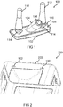
- FIG. 1 shows a light guide 100 for guiding light into a cooking chamber of a cooking appliance according to an embodiment.
- the light-conducting device 100 has a light-out coupling element 102 and a light-coupling element 104.
- the light guide device 100 can be attached to a wall of the cooking chamber.
- the light extraction element 102 has an abutment side, in FIG. 1 the overhead side, on, with the light output element 102 rests in the mounted state on the wall of the cooking chamber. In this case, the light output element 102 is located in the interior of the cooking chamber. Opposite to the contact side, the light output element 102 has a curved outcoupling surface.
- the contact side comprises a base surface 106.
- the light coupling element 104 extends rod-shaped out of the base 106 and is, for example, cylindrically shaped.
- the light coupling element 104 has a coupling-in surface 108, via which light can be coupled into the light coupling element 104 during operation of the cooking appliance.
- the light coupled into the coupling surface 108 is conducted by the light coupling element 104 to the light coupling element 102 and leaves the light coupling element 102 via the decoupling surface.
- the light extraction element 104 according to an embodiment of an optical element in the form of a lens.
- the light extraction element 102 is aligned obliquely to the base. As a result, the overall height of the light-guiding device 100 can be kept low.
- the base area 106 is enclosed by a continuous circumferential sealing edge 110 which projects beyond the base area 106.
- the light-guiding device 100 comprises at least one latching dome 112, in accordance with the exemplary embodiment shown two latching domes 112, wherein the light coupling element 104 is arranged between the two latching domes 112.
- the two locking domes 112 are aligned at right angles to the base surface 106.
- the locking domes 112 have a cylindrical end section, an adjoining conical section widening in the direction of the base surface 106 and a latching device 114 arranged between the conical section and the base surface 106.
- the latching device 114 is formed as a circumferential brim and is used in the assembly of the light guide device 100 to attach the light guide 100 to the wall of the cooking chamber. For this purpose, the locking domes 112 are pulled through passage openings in the wall.
- the light-guiding device 100 is integrally formed from plastic, for example made of silicone.
- FIG. 1 According to one exemplary embodiment, a 3D representation of a light-guiding device 100 in the form of a silicone component is shown.
- the light output element 102 also referred to as Lichtauslasselement, on different steep edges, wherein the light output element 102 is aligned in the mounted state with the steep edge to the door and with the flat edge to the cooking chamber interior.
- the light output element 102 has, according to one embodiment, different curvatures and angles, which serve to rectify the coupled-in light waves in order to achieve the lowest possible power loss.
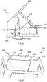
- the Figures 2 and 7 show a cooking chamber 220, wherein on a wall 222 of the cooking chamber 220 two light-guiding devices are arranged, of which each Auskoppel vom the light output elements 102 can be seen.
- the light-guiding devices can ever be act a device as they are based on FIG. 1 is described. Shown is thus a view of the cooking chamber 220 with lights from the inside.
- At least one lighting device arranged on the wall 222 serving as a ceiling is sufficient to completely illuminate the cooking space.
- a very small number of LEDs is sufficient for a good lighting result.
- no separate optics to optimize the light distribution are required.
- the assembly can be realized with little complexity and it is not necessary to secure the unit with screws.
- the lamp used can be arranged outside the cooking chamber 220, a susceptibility of the illumination by microwave radiation is not relevant. Interchangeability in the case of customer service is facilitated by good accessibility. In particular, no complex disassembly of the device is required to replace the lighting device.
- the lighting is arranged in the front right and left corner of the cooking chamber.
- the orientation of the optics which is formed according to an embodiment by the Lichtauskoppelmaschine 102, obliquely directed backwards against the cooking chamber bottom and the rear wall of the cooking chamber 220.
- the cooking chamber 220 has a cooking chamber opening which is delimited by a cooking chamber edge 225.
- the two lighting devices 440 are preferably arranged on the cooking chamber ceiling, in particular symmetrically to the cooking chamber opening. In this case, the spacing between the lighting devices 440 corresponds to 1.5 times to 2.5 times the outer distance of the individual lighting devices 440 to the nearest cooking chamber side wall. From the cooking chamber edge 225, the lighting devices 440 have the same distance, which is in the range of 20 millimeters to 120 millimeters.
- FIG. 3 shows a section of the basis of FIG. 3 described cooking chamber 220 with a light guide. Evident is a curved outcoupling surface 330 of the light output element 102nd
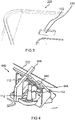
- FIG. 4 shows a lighting device 440 for illuminating a cooking chamber of a cooking appliance according to an embodiment.
- the basis of FIG. 3 shown light guide can be part of the basis of FIG. 4 be described lighting device 440.
- the illumination device 440 comprises a light guide device, of which in FIG. 4 the two locking domes 112 and the light coupling element 104 can be seen, a board 442 with a light source 444 for providing light, and a board holder 446 for holding the board 442.
- the board holder 446 is held on the locking dome 112 on the wall 222 of the cooking chamber and abuts on the wall 222 via at least one support surface.
- the board holder 446 is formed to hold the board 442 obliquely with respect to the wall 222, here for example at right angles to the light coupling element 104.
- the coupling surface of the light coupling element 104 is applied to the light source 444, so that light emitted by the light source 444 is coupled directly into the light coupling element 104.
- the light guiding device made of silicone according to one embodiment is also referred to as optics.
- the board holder 446 is exemplified by plastic.
- the wall 222 forms a Garraummantel according to an embodiment.
- the light-guiding device also referred to as a lighting unit
- the light output element is applied to the inside of the ceiling forming wall 222.
- the two locking domes 112 and the light coupling element 104 are out through a defined hole pattern in the wall 222 to the outside, so out of the oven out.
- the board holder 446 holds the optics in position, thereby the locking dome 112 are pulled with an excess through the cooking chamber ceiling forming wall 222 and receiving holes in the board holder 446, behind which they lock.
- the inner part of the optics is clamped against the wall 222, here the ceiling, the cooking chamber and additionally assumes the sealing function.
- a recording on the board holder 446 ensures the always same position of the light coupling element 104 after assembly, so that after the snap-in of the board 442, the orientation of the lamp 448, for example an LED to the coupling element 104 is ensured.
- the position of the board 442 is selected at an angle to the wall 222 formed as cooking chamber ceiling.
- an angle of incidence of the board of, for example, 45 ° from the angle of the light guide, here the Lichteinkoppelelement 104 to the wall 222.
- the radiation characteristic of the bulb 448 requires, according to an embodiment for optimal coupling, the rectangular orientation of the light source serving as light source 448 to the optics.
- the holder 446 loosely rests on the cooking chamber and is fixed with the light-guiding device designed as a light guide.
- the executed according to one embodiment as a silicone component light guide device is only mechanically (positive and positive fit) connected to the formed as a plastic part board holder 446.
- the circuit board 442 with the luminous means 448 is mounted at a defined distance from the coupling-in region, that is to say the coupling-in surface of the light coupling element 104.
- the board 442 has, according to one embodiment, a heat-dissipating layer, so that the board 442 as a whole functions as a heat sink
- an insertion of the light guide takes place from the inside into the cooking chamber.
- a placement of the board holder 446 takes place from the outside to the cooking chamber.
- a threading of the locking dome 112 through the receiving holes of the holder 446 It follows a traversing the undercut geometry of the locking dome 112 by means of the cylindrical extension of the locking dome 112 through the receiving holes of the board holder 446.
- the installation is possible only in one direction, since the rotation of the holder 446 is prevented by the embossing of the wall 222 designed as a cooking chamber ceiling.
- the Figures 5 and 6 show a cross-sectional view of the basis of FIG. 4 described lighting device 440 according to one embodiment.
- the board holder 446 has a latching nose, by means of which the board 442 can be fixed.
- the optics of the illumination device 440 formed by the light guide device serves as a seal, and in cooperation with the board holder 446 as a locking partner.
- the securing, alignment, attachment and sealing of the cooking chamber with respect to the also designated as lighting unit board 442 and the light guide is realized by the connection of two components, here the board holder 446 and the locking domes 112.
- the system gets by an undercut connection without screws.
- a good Dogdienstrate is achieved according to an embodiment by the placement of the bulb 444 in a more neutral radiation range of a microwave of the cooking appliance.
- a simple assembly and disassembly is possible. It is also possible to save a seal or additional systemic components.
Landscapes
- Engineering & Computer Science (AREA)
- Physics & Mathematics (AREA)
- Electromagnetism (AREA)
- Chemical & Material Sciences (AREA)
- Combustion & Propulsion (AREA)
- Mechanical Engineering (AREA)
- General Engineering & Computer Science (AREA)
- Electric Ovens (AREA)
- Non-Portable Lighting Devices Or Systems Thereof (AREA)
Abstract
Description
- Die Erfindung betrifft eine Lichtleitvorrichtung zum Leiten von Licht in einen Garraum eines Gargeräts, eine Beleuchtungsvorrichtung und ein Gargerät, wie beispielsweise ein Mikrowellengerät.
- Ein Garraum eines Gargeräts, beispielsweise eines Dampfgarers, ist üblicherweise beleuchtet, um einer Bedienperson einen Einblick in den Garraum zu ermöglichen.
- Der Erfindung stellt sich die Aufgabe eine verbesserte Lichtleitvorrichtung zum Leiten von Licht in einen Garraum eines Gargeräts, eine verbesserte Beleuchtungsvorrichtung und ein verbessertes Gargerät zu schaffen.
- Erfindungsgemäß wird diese Aufgabe durch eine Lichtleitvorrichtung zum Leiten von Licht in einen Garraum eines Gargeräts, eine Beleuchtungsvorrichtung und ein Gargerät mit den Merkmalen der Hauptansprüche gelöst. Vorteilhafte Ausgestaltungen und Weiterbildungen der Erfindung ergeben sich aus den nachfolgenden Unteransprüchen.
- Die mit der Erfindung erreichbaren Vorteile bestehen neben einer Einsparung von Bauraum in einer Erhöhung der Zugänglichkeit und einer Montageerleichterung.
- Eine Lichtleitvorrichtung zum Leiten von Licht in einen Garraum eines Gargeräts weist die folgenden Merkmale auf:
- ein Lichtauskoppelelement mit einer Anliegeseite zum fluiddichten Anliegen an einer Innenseite einer Wand des Garraums und einer der Anliegeseite gegenüberliegenden Außenseite, wobei die Anliegeseite eine Grundfläche umfasst und die Außenseite eine gewölbte Auskoppelfläche zum gerichteten Auskoppeln von Licht aus dem Lichtauskoppelelement aufweist; und
- ein sich von der Grundfläche aus erstreckendes stabförmiges Lichteinkoppelelement mit einer außerhalb des Garraums anordenbaren Einkoppelfläche zum Einkoppeln von Licht.
- Das stabförmige Lichteinkoppelelement ist bevorzugt in einem Winkel zu dem Lichtauskoppelelement und/oder der Wand des Garraums und/oder zu der Grundfläche orientiert. Dieser Winkel des stabförmigen Lichteinkoppelelementes weicht von der Lotrechten zum Lichtauskoppelelement und/oder zur Wand des Garraums und/oder der Grundfläche ab. Der Winkel des stabförmigen Lichteinkoppelelementes ist in einem Bereich zwischen 10 Grad und 80 Grad, vorzugsweise in einem Bereich von 25 Grad bis 75 Grad zu dem Lichtauskoppelelement und/oder zu der Wand des Garraums.
- Als besonders vorteilhaft hat es sich erwiesen, dass das stabförmige Lichteinkoppelelement in einem Winkel von 45 Grad zu dem Lichtauskoppelelement und/oder der Wand des Garraums und/oder der Grundfläche orientiert. Hierdurch ist einerseits eine gute Ausleuchtung des Garraums möglich, andererseits ist diese hierdurch für einen in den Garraum hineinblickenden Benutzer blendfrei ausgeführt.
- Bei einer Positionierung der Lichtleitvorrichtung in einer Wand des Garraumes nah an der Garraumöffnung ist das Lichteinkoppelelement zur Garraumöffnung hin geneigt. Gerade durch diese Neigung kann die blendfreie Ausgestaltung bei zugleich guter Ausleuchtung des Garraumes besonders effektiv erreicht werden.
- Das Gargerät kann zum Erwärmen von Speisen verwendet werden, die in den Garraum gestellt werden können. Dazu kann das Gargerät eine geeignete Heizeinrichtung, beispielsweise eine Mikrowellenantenne oder einen Heizdraht aufweisen. Das aus der Auskoppelfläche ausgekoppelte Licht kann zum Ausleuchten des Garraums verwendet werden. Das Lichtauskoppelelement kann einen Lichtleiter ausformen, durch den Licht von außerhalb des Garraums in den Garraum hineingeleitet wird. Durch die gewölbte Auskoppelfläche kann die Funktionalität einer Linse erreicht werden. Eine Wölbung der Auskoppelfläche kann dabei so gewählt werden, das eine gewünschte Lichtverteilung innerhalb des Garraums erreicht wird.
- Vorteilhafterweise ist es unter Verwendung der Lichtleitvorrichtung nicht erforderlich, eine oder mehrere Leuchtdioden innerhalb des Garraums anzuordnen. Im Unterschied zu einer Beleuchtung, die mittig unter der Decke des Garraumes angeordnet ist, kann die den Garraum bildenden Kavität unter Verwendung der Lichtleitvorrichtung auch dann ausgeleuchtet werden, wenn ein Behälter auf einer obersten Ebene des Garraums eingeschoben wird. Dieser schluckt dann nicht das ganze Licht.
- Die Lichtleitvorrichtung kann einen sich von der Grundfläche aus erstreckenden stabförmigen Rastdom mit einer Rasteinrichtung zum Verrasten des Rastdoms an der Wand des Garraums aufweisen. Der Rastdom kann beim Montieren der Lichtleitvorrichtung durch eine Durchgangsöffnung der Wand geführt werden. Der Rastdom kann somit zum Montieren und Befestigen der Lichtleitvorrichtung an der Wand des Garraums genutzt werden.
- Dabei kann der Rastdom rechtwinklig zu der Grundfläche ausgerichtet sein. Dadurch kann der Kraftaufwand zum Durchführen des Rastdoms durch die Durchgangsöffnung reduziert werden.
- Die Lichtleitvorrichtung kann einen weiteren sich von der Grundfläche aus erstreckenden stabförmigen Rastdom mit einer Rasteinrichtung zum Verrasten des Rastdoms an der Wand des Garraums aufweisen. Dabei kann das Lichteinkoppelelement zwischen dem Rastdom und dem weiteren Rastdom angeordnet sein. Dadurch kann die Lichtleitvorrichtung sicher an der Wand befestigt werden.
- Das Lichtauskoppelelement und/oder das Lichteinkoppelelement können schräg zu der Grundfläche ausgerichtet sein. Dadurch kann der Bauraum gering gehalten beziehungsweise eine vorteilhafte Lichtführung erreicht werden.
- Gemäß einer Ausführungsform ist das Lichteinkoppelelement relativ zu dem wenigstens einen Rastdom geneigt. Insbesondere bei mehreren Rastdomen sind deren Längsachsen parallel im Raum orientiert. In einer bevorzugten Ausführungsform liegen die Längsachsen von zwei Rastdomen in einer gemeinsamen Rastebene und das Lichteinkoppelelement ist auf einer zur Rastebene senkrechten Verschwenkebene in einem Winkel von 15 Grad bis 75 Grad, insbesondere 45 Grad, zu der Rastebene geneigt. Eine Variante dieser Ausführungsform sieht vor, dass die Längsachse des Lichteinkoppelelementes die Rastebene im Bereich der Wand des Garraumes schneidet. Als Bereich der Bereich der Wand des Garraumes ist die Mächtigkeit der Wand zugüglich 10 Millimeter auf der Garraumseite und 10 Millimeter auf der dem Garraum abgewandten Seite zu verstehen.
- Das Lichtauskoppelelement kann ein optisches Element ausformen. Ein solches optisches Element kann eine Linse sein. Beispielsweise kann das Lichtauskoppelelement auf diese Weise als ein Kollimator dienen.
- Die Anliegeseite des Lichtauskoppelelements kann einen die Grundfläche umschließenden und über die Grundfläche hervorstehenden Dichtungsrand aufweisen. Durch den Dichtungsrand kann verhindert werden, das Dampf aus dem Garraum austreten kann.
- Die Lichtleitvorrichtung kann einstückig ausgeformt sein. Dadurch können Herstellungskosten gering gehalten werden.
- Beispielsweise kann die Lichtleitvorrichtung aus Silikon ausgeformt sein. Silikon ist aufgrund seiner Hitzebeständigkeit und Elastizität sehr gut geeignet. Als besonders vorteilhaft erwiesen hat es sich, dass die Lichtleitvorrichtung einen Brechungsindex nD25 aufweist, welcher dem von Glas entspricht oder geringer ist. Hierdurch wird eine gute Ausleuchtung und ein hoher Wirkungsgrad der Beleuchtungsvorrichtung zur Verfügung gestellt. Der Brechungsindex ist demnach kleiner als 1,5200, insbesondere kleiner als 1,4600.
- Bevorzugt ist der Brechungsindex nD25 der Lichtleitvorrichtung in einem Bereich von 1,3600 bis 1,4300. Dieser Bereich entspricht dem Brechungsindex des menschlichen Auges, so dass eine hohe Farbtreue mit dem Licht der Beleuchtungsvorrichtung möglich wird. Besonders bevorzugt ist der Brechungsindex nD25 in einem Bereich von 1,4000 bis 1,4300, insbesondere in einem Bereich von 1,4100 bis 1,4199.
- Dem gegenüber geht, insbesondere bei Silikonmaterialien, ein größerer Brechungsindex mit einer geringeren Transparenz und einer größeren Streuung einher. Hierraus ergibt sich der Vorteil, dass die Beleuchtungsvorrichtung weniger zum Blenden neigt und eine reduzierte Spotbildung aufweist. Hier hat es sich als vorteilhaft erwiesen, dass der Brechungsindex nD25 der Lichtleitvorrichtung in einem Bereich von 1,4900 bis 1,4300, insbesondere in einem Bereich von 1,4500 bis 1,4600.
- Unter Berücksichtigung des Vorstehend angeführten Zielkonfliktes nach einerseits einem möglichst geringen Brechungsindex und andererseits einem moderat hohen Brechungsindex hat es sich als brauchbaren Kompromiss erwiesen, dass der Brechungsindex nD25 der Lichtleitvorrichtung in einem Bereich von 1,4100 bis 1,4600 liegt.
- Eine Beleuchtungsvorrichtung zum Beleuchten eines Garraums eines Gargeräts weist die folgenden Merkmale auf:
- eine genannte Lichtleitvorrichtung;
- eine Platine mit einem Leuchtmittel; und
- einen Platinenhalter zum Halten der Platine mit dem Leuchtmittel gegenüberliegend zu der Einkoppelfläche des Lichteinkoppelelements der Lichtleitvorrichtung, wobei der Platinenhalter eine Auflagefläche zum Auflegen des Platinenhalters auf eine Außenseite der Wand des Garraums aufweist.
- Unter einer Platine kann eine Leiterplatte verstanden werden, die das Leuchtmittel trägt. Die Platine kann einen elektrischen Anschluss für eine Energieversorgung des Leuchtmittels aufweisen. Bei dem Leuchtmittel kann es sich um eine Leuchtdiode handeln.
- Nach einer Ausführungsform ist der Platinenhalter mit der Lichtleitvorrichtung einteilig ausgeführt, insbesondere gemeinsam mit der Lichtleitvorrichtung urgeformt.
- Im Kundendienstfall ist ein Austausch der als Beleuchtung fungierenden Beleuchtungsvorrichtung sehr einfach, da der Zugang zu der Baugruppe nicht die Demontage anderer Komponenten erfordert. Zudem ist eine Ausfallrate der Beleuchtung sehr gering, da die Ausfallrate direkt mit der Nutzung der Mikrowellenfunktion zusammenzuhängen scheint, und die Beleuchtungsvorrichtung, auch Beleuchtungseinheit genannt, entfernt von dem größten Potential verbaut werden kann.
- Die Beleuchtungsvorrichtung ist bevorzugt nah an der Garraumöffnung, insbesondere an der Garraumdecke hinter einer Bedienblende angeordnet. Hierdurch wird ein möglicher Austausch der Baugruppe erleichtert. Gemäß einer bevorzugten Ausführungsform ist die Platine näher an der Ebene der Garraumöffnung angeordnet als die Lichtleitvorrichtung, insbesondere deren Lichteinkoppelelement.
- Eine Ausführungsform sieht vor, dass die Platine mit einer Neigung zu der Wand des Garraumes und/oder einem Lichtauskoppelelement der Lichtleitvorrichtung und/oder der Grundfläche gehalten ist. Diese Neigung ist vorzugsweise in einem Bereich zwischen 10 Grad und 80 Grad, besonders bevorzugt in einem Bereich von 25 Grad bis 75 Grad zu dem Lichtauskoppelelement und/oder zu der Wand des Garraums.
- Als besonders vorteilhaft hat es sich erwiesen, dass die Platine in einem Winkel von 45 Grad zu dem Lichtauskoppelelement und/oder der Wand des Garraums und/oder der Grundfläche orientiert ist. Dies ermöglicht bei der Montage und im Kundendienstfall eine gute Handhabung.
- Eine ergänzende oder alternative Ausprägung der Beleuchtungsvorrichtung sieht vor, dass die Platine in montierter Position rechtwinklig zu dem Lichteinkoppelelement der Lichtleitvorrichtung orientiert ist.
- Ein Gargerät kann vorteilhaft mit einer genannten Beleuchtungsvorrichtung ausgerüstet werden. Im montierten Zustand der Beleuchtungsvorrichtung ist das Lichteinkoppelelement der Lichtleitvorrichtung durch eine Durchgangsöffnung der Wand des Garraums geführt und die Anliegeseite des Lichtauskoppelelements der Lichtleitvorrichtung liegt an der Wand an. Die genannte Wand kann eine Decke des Garraums ausformen.
- Gemäß einer Ausführungsform ist zumindest eine Beleuchtungsvorrichtung an einer Tür beziehungsweise Garraumöffnung, insbesondere Beschickungsöffnung, des Garraums zugwandten Seite der Wand angeordnet.
- Eine günstige Ausführungsform sieht vor, dass die zumindest eine Beleuchtungseinrichtung von der Garraumöffnung beziehungsweise von einem die Ebene der Garraumöffnung aufspannenden Garraumrand einen Abstand zwischen 30 und 120 Millimeter aufweist. Bei mehreren Beleuchtungseinrichtungen haben diese vorzugsweise den selben Abstand zur Ebene bzw. zum Garraumrand.
- Vorzugsweise ist die Beleuchtungsvorrichtung in der Decke des Garraumes angeordnet. Dabei hat sich als Position am vorteilhaftesten herausgestellt eine Anordnung im Mittenbereich bezogen auf die Garraumöffnung. Bei einem Gargerät mit mehreren Beleuchtungseinrichtungen sind diese gleichmäßig und/oder symmetrisch zum Mittenbereich verteilt angeordnet.
- Bei dem Gargerät kann es sich um ein Haushaltgerät oder ein gewerbliches oder professionelles Gerät handeln.
- Ein Ausführungsbeispiel der Erfindung ist in den Zeichnungen rein schematisch dargestellt und wird nachfolgend näher beschrieben. Es zeigt
- Figur 1
- eine Lichtleitvorrichtung zum Leiten von Licht in einen Garraum eines Gargeräts;
- Figur 2
- einen Garraum mit Lichtleitvorrichtungen;
- Figur 3
- einen Abschnitt eines Garraums mit einer Lichtleitvorrichtung;
- Figur 4
- eine Beleuchtungsvorrichtung zum Beleuchten eines Garraums eines Gargeräts;
- Figur 5
- eine Querschnittsdarstellung der anhand von
Figur 4 beschriebenen Beleuchtungsvorrichtung; - Figur 6
- eine weitere Querschnittsdarstellung der anhand von
Figur 4 beschriebenen Beleuchtungsvorrichtung; - Figur 7
- einen Garraum mit Lichtleitvorrichtungen.
-
Figur 1 zeigt eine Lichtleitvorrichtung 100 zum Leiten von Licht in einen Garraum eines Gargeräts gemäß einem Ausführungsbeispiel. Die Lichtleitvorrichtung 100 weist ein Lichtauskoppelelement 102 und ein Lichteinkoppelelement 104 auf. Die Lichtleitvorrichtung 100 kann an einer Wand des Garraums befestigt werden. - Das Lichtauskoppelelement 102 weist eine Anliegeseite, in
Figur 1 die oben liegende Seite, auf, mit der das Lichtauskoppelelement 102 im montierten Zustand an der Wand des Garraums anliegt. Dabei befindet sich das Lichtauskoppelelement 102 im Inneren des Garraums. Gegenüberliegend zu der Anliegeseite weist das Lichtauskoppelelement 102 eine gewölbte Auskoppelfläche auf. - Die Anliegeseite umfasst eine Grundfläche 106. Das Lichteinkoppelelement 104 erstreckt sich stabförmig aus der Grundfläche 106 heraus und ist beispielsweise zylinderförmig ausgeformt. Das Lichteinkoppelelement 104 weist eine Einkoppelfläche 108 auf, über die im Betrieb des Gargeräts Licht in das Lichteinkoppelelement 104 eingekoppelt werden kann. Das in die Einkoppelfläche 108 eingekoppelte Licht wird von dem Lichteinkoppelelement 104 zu dem Lichtauskoppelelement 102 geleitet und verlässt das Lichtauskoppelelement 102 über die Auskoppelfläche. Dabei form das Lichtauskoppelelement 104 gemäß einem Ausführungsbeispiel ein optisches Element in Form einer Linse aus.
- Gemäß einem Ausführungsbeispiel ist das Lichtauskoppelelement 102 schräg zu der Grundfläche ausgerichtet. Dadurch kann die Bauhöhe der Lichtleitvorrichtung 100 gering gehalten werden.
- Gemäß einem Ausführungsbeispiel ist die Grundfläche 106 von einem durchgängig umlaufenden Dichtungsrand 110 umschlossen, der über die Grundfläche 106 hervorsteht.
- Optional umfasst die Lichtleitvorrichtung 100 zumindest einen Rastdom 112, gemäß dem gezeigten Ausführungsbeispiel zwei Rastdome 112, wobei das Lichteinkoppelelement 104 zwischen den zwei Rastdomen 112 angeordnet ist. Die beiden Rastdomen 112 sind rechtwinklig zur Grundfläche 106 ausgerichtet.
- Die Rastdome 112 weisen einen zylinderförmigen Endabschnitt, einen daran anschließenden sich in Richtung der Grundfläche 106 verbreiternden kegelförmigen Abschnitt und eine zwischen dem kegelförmigen Abschnitt und der Grundfläche 106 angordnete Rasteinrichtung 114 auf. Die Rasteinrichtung 114 ist als eine umlaufende Krempe ausgeformt und wird bei der Montage der Lichtleitvorrichtung 100 verwendet, um die Lichtleitvorrichtung 100 an der Wand des Garraums zu befestigen. Dazu werden die Rastdome 112 durch Durchgangsöffnungen in der Wand gezogen.
- Gemäß einem Ausführungsbeispiel ist die Lichtleitvorrichtung 100 einstückig aus Kunststoff, beispielsweise aus Silikon, ausgeformt.
- In
Figur 1 ist gemäß einem Ausführungsbeispiel eine 3D-Darstellung einer Lichtleitvorrichtung 100 in Form eines Silikonbauteils gezeigt. - Gemäß einem Ausführungsbeispiel weist das Lichtauskoppelelement 102, auch als Lichtauslasselement bezeichnet, unterschiedlich steile Flanken auf, wobei das Lichtauskoppelelement 102 im montierten Zustand mit der steilen Flanke zur Tür und mit der flachen Flanke zum Garrauminneren ausgerichtet ist.
- Das Lichtauskoppelelement 102 weist gemäß einem Ausführungsbeispiel unterschiedliche Krümmungen und Winkel auf, die der Gleichrichtung der eingekoppelten Lichtwellen dienen, um eine möglichst geringe Verlustleistung zu erreichen.
- Die
Figuren 2 und7 zeigen einen Garraum 220, wobei an einer Wand 222 des Garraums 220 zwei Lichtleitvorrichtungen angeordnet sind, von denen jeweils Auskoppelflächen der Lichtauskoppelelemente 102 zu sehen sind. Bei den Lichtleitvorrichtungen kann es sich je um eine Vorrichtung handeln, wie sie anhand vonFigur 1 beschrieben ist. Gezeigt ist somit eine Ansicht des Garraums 220 mit Leuchten von Innen. - Vorteilhafterweise ist es unter Verwendung der Lichtleitvorrichtungen nicht erforderlich, die Beleuchtung in allen Bereichen Wände des Garraums 220 zur realisieren. Es reicht zumindest eine an der als Decke dienenden Wand 222 angeordnete Beleuchtungsvorrichtung aus, um den Garraum vollständig auszuleuchten. Dadurch ist eine sehr geringe Anzahl von LED's für ein gute Beleuchtungsergebnis ausreichend. Zudem sind keine separate Optiken zur Optimierung der Lichtverteilung erforderlich. Die Montage kann wenig komplex realisiert werden und es ist keine Sicherung der Einheit mit Schrauben erforderlich. In dem das verwendete Leuchtmittel außerhalb des Garraums 220 angeordnet werden kann, ist eine Anfälligkeit der Beleuchtung durch Mikrowellestrahlung nicht relevant. Eine Austauschbarkeit im Kundendienstfall wird durch eine gute Zugänglichkeit erleichtert. Insbesondere ist keine komplexe Demontage des Gerätes erforderlich, um die Beleuchtungsvorrichtung auszutauschen.
- Durch den hier beschriebenen Ansatz wird eine gute Ausleuchtung der Kavität des Garraums 220 unabhängig von der gewählten Einschubebene erreicht. Ferner ist eine Optimierung des Montageprozesse durch den Verzicht auf Schrauben gegeben. Es ergibt sich zum dem eine sehr hohe Lebensdauer der Leuchtmittel, beispielsweise in Form von LED's und es genügen ein oder zwei Leuchtmittel zum Ausleuchten des gesamten Garraums 220.
- Somit ergibt sich ein Verringern der erforderlichen Leuchtmittel bei vergleichbarer oder besserer Ausleuchtung im Vergleich zu der Anordnung von Leuchtmitteln im Inneren des Garraums 220. Gemäß einem Ausführungsbeispiel ist die Beleuchtung in der vorderen rechten und linken Ecke der Garraumdecke angeordnet. Dabei ist die Ausrichtung der Optik, die gemäß einem Ausführungsbeispiel durch die Lichtauskoppelelemente 102 ausgeformt wird, schräg nach hinten gegen den Garraumboden und die Rückwand des Garraums 220 gerichtet.
- Der Garraum 220 hat eine Garraumöffnung, welche durch einen Garraumrand 225 begrenzt ist. Die zwei Beleuchtungsvorrichtungen 440 sind bevorzugt an der Garraumdecke, insbesondere symmetrisch zur Garraumöffnung, angeordnet. Dabei entspricht der Zwischenabstand der Beleuchtungsvorrichtungen 440 zueinander dem 1,5-fachen bis 2,5-fachen des Außenabstandes der einzelnen Beleuchtungsvorrichtungen 440 zur nächstliegenden Garraum-Seitenwand. Von dem Garraumrand 225 haben die Beleuchtungsvorrichtungen 440 den gleichen Abstand, welcher im Bereich von 20 Millimeter bis 120 Millimeter liegt.
-
Figur 3 zeigt einen Abschnitt des anhand vonFigur 3 beschriebenen Garraums 220 mit einer Lichtleitvorrichtung. Zu erkennen ist eine gewölbte Auskoppelfläche 330 des Lichtauskoppelelements 102. -
Figur 4 zeigt eine Beleuchtungsvorrichtung 440 zum Beleuchten eines Garraums eines Gargeräts gemäß einem Ausführungsbeispiel. Die anhand vonFigur 3 gezeigte Lichtleitvorrichtung kann Teil der anhand vonFigur 4 beschriebenen Beleuchtungsvorrichtung 440 sein. - Die Beleuchtungsvorrichtung 440 umfasst eine Lichtleitvorrichtung, von der in
Figur 4 die zwei Rastdome 112 und das Lichteinkoppelelement 104 zu erkennen sind, eine Platine 442 mit einem Leuchtmittel 444 zum Bereitstellen von Licht, und einen Platinenhalter 446 zum Halten der Platine 442. Der Platinenhalter 446 wird über die Rastdome 112 an der Wand 222 des Garraums gehalten und liegt über zumindest eine Auflagefläche an der Wand 222 an. Der Platinenhalter 446 ist ausgeformt, um die Platine 442 schräg gegenüber der Wand 222, hier beispielsweise rechtwinklig zu dem Lichteinkoppelelement 104, zu halten. Die Einkoppelfläche des Lichteinkoppelelements 104 liegt an dem Leuchtmittel 444 an, sodass von dem Leuchtmittel 444 ausgestrahltes Licht direkt in das Lichteinkoppelelement 104 eingekoppelt wird. - Die gemäß einem Ausführungsbeispiel aus Silikon hergestellte Lichtleitvorrichtung wird auch als Optik bezeichnet. Der Platinenhalter 446 ist beispielhaft aus Kunststoff. Die Wand 222 bildet gemäß einem Ausführungsbeispiel einen Garraummantel.
- Zur Montage wird die auch als Beleuchtungseinheit bezeichnete Lichtleitvorrichtung an der Decke des Garraummantels, hier der Wand 222 montiert. Das Lichtauskoppelelement liegt an der Innenseite der die Decke ausformenden Wand 222 an. Die zwei Rastdome 112 und das Lichteinkoppelelement 104 werden durch ein definiertes Lochbild in der Wand 222 nach außen, also aus dem Garraum heraus, geführt. Der Platinenhalter 446 hält die Optik in Position, dabei werden die Rastdome 112 mit einem Übermaß durch die Garraumdecke ausformenden Wand 222 und Aufnahmelöcher im Platinenhalter 446 gezogen, hinter dem sie verrasten. Der innen liegende Teil der Optik wird dabei gegen die Wand 222, hier die Decke, des Garraumes gespannt und übernimmt zusätzlich die Dichtfunktion.
- Eine Aufnahme am Platinenhalter 446 stellt die immer gleiche Position des Lichteinkoppelelementes 104 nach der Montage sicher, so dass nach dem Einrasten der Platine 442, die Ausrichtung des Leuchtmittels 448, beispielsweise einer LED zum Einkoppelelement 104 gewährleistet ist.
- Die Position der Platine 442 ist unter einem Winkel zur als Garraumdecke ausgeformten Wand 222 gewählt. Dabei resultiert ein Anstellwinkel der Platine von beispielsweise 45° aus dem Winkel des Lichtleiters, hier des Lichteinkoppelelement 104 zur Wand 222. Die Abstrahlcharakteristik des Leuchtmittels 448 erfordert gemäß einem Ausführungsbeispiel für eine optimale Einkopplung die rechtwinkelige Ausrichtung des als Lichtquelle dienenden Leuchtmittels 448 zur Optik. Der Winkel resultiert aus den Rahmenbedingungen für die Lichteinkopplung, dem maximal möglichen Anstellwinkel in Abhängigkeit zum maximalen Öffnungsdurchmesser von beispielsweise d = 7 mm an der Wand 222 und dem damit möglichen maximalen Querschnitt des Lichtleiters in Form des Lichteinkoppelelements 104.
- Der Halter 446 liegt gemäß einem Ausführungsbeispiel erst lose auf dem Garraum auf und wird mit der als Lichtleiter ausgeführten Lichtleitvorrichtung fixiert.
- Die gemäß einem Ausführungsbeispiel als Silikonbauteil ausgeführte Lichtleitvorrichtung ist nur mechanisch (kraft- und formschlüssig) mit dem als Kunststoffteil ausgeformten Platinenhalter 446 verbunden.
- Die Platine 442 mit dem Leuchtmittel 448 ist mit einem definierten Abstand zum Einkoppelbereich, also der Einkoppelfläche des Lichteinkoppelelements 104 montiert. Die Platine 442 besitzt gemäß einem Ausführungsbeispiel eine wärmeableitende Schicht, so dass die Platine 442 im Ganzen als Kühlkörper funktioniert
- Bei der Montage werden die im Folgenden ausgeführten Montageschritte ausgeführt. Zunächst erfolgt ein Einsetzen der Lichtleitvorrichtung von innen in den Garraum. Anschließend erfolgt ein Aufsetzen des Platinenhalters 446 von außen auf den Garraum. Dabei erfolgt ein Einfädeln der Rastdome 112 durch die Aufnahmelöcher des Halters 446. Es folgt ein Durchziehen der hinterschnittigen Geometrie der Rastdome 112 mittels der zylindrischen Verlängerung der Rastdome 112 durch die Aufnahmelöcher des Platinenhalters 446. Es folgt ein Einsetzen der Platine 442 auf den unteren Rand der Stützgeometrie des Platinenhalters 446, ein Überkippen der Platine 442 bis diese hinter der Feder des Halters 446 einrastet. Der Einbau ist gemäß einem Ausführungsbeispiel nur in einer Richtung möglich, da die Verdrehung des Halters 446 durch die Prägung der als Garraumdecke ausgeführten Wand 222 verhindert wird. Gleiches gilt für die Montage der Platine 442, da die Geometrien des Halters 446 einen unsachgemäßen Einbau verhindern.
- Die
Figuren 5 und6 zeigen eine Querschnittsdarstellung der anhand vonFigur 4 beschriebenen Beleuchtungsvorrichtung 440 gemäß einem Ausführungsbeispiel. Der Platinenhalter 446 weist eine Rastnase auf, durch die die Platine 442 fixiert werden kann. - Die durch die Lichtleitvorrichtung gebildete Optik der Beleuchtungsvorrichtung 440 dient als Dichtung, und im Zusammenspiel mit dem Platinenhalter 446 als Rastpartner. Die Sicherung, Ausrichtung, Befestigung und Abdichtung des Garraumes gegenüber der auch als Beleuchtungseinheit bezeichneten Platine 442 und der Lichtleitvorrichtung wird durch die Verbindung von zwei Bauteilen, hier dem Platinenhalter 446 und den Rastdomen 112, realisiert. Das System kommt durch eine hinterschnittige Verbindung ohne Schrauben aus. Eine gute Kundendienstrate wird gemäß einem Ausführungsbeispiel durch die Platzierung des Leuchtmittels 444 in einem neutraleren Strahlungsbereich einer Mikrowelle des Gargeräts erreicht.
- Vorteilhafterweise ist eine einfache Montage und Demontage möglich. Es wird zudem das Einsparen einer Dichtung oder zusätzlicher systembedingter Komponenten möglich. Zudem ergibt sich eine sichere Positionierung, eine hohe Toleranzunempfindlichkeit und für den Anwendungsfall eines Mikrowellengeräts wird der Einfluss der Milkrowellenstrahlung auf die Lebensdauer des Leuchmittels 444, beispielsweise einer LED, optimiert.
Claims (12)
- Lichtleitvorrichtung (100) zum Leiten von Licht in einen Garraum (220) eines Gargeräts, wobei die Lichtleitvorrichtung (100) die folgenden Merkmale aufweist:ein Lichtauskoppelelement (102) mit einer Anliegeseite zum fluiddichten Anliegen an einer Innenseite einer Wand (222) des Garraums (220) und einer der Anliegeseite gegenüberliegenden Außenseite, wobei die Anliegeseite eine Grundfläche (106) umfasst und die Außenseite eine gewölbte Auskoppelfläche (330) zum gerichteten Auskoppeln von Licht aus dem Lichtauskoppelelement (102) aufweist; undein sich von der Grundfläche (106) aus erstreckendes stabförmiges Lichteinkoppelelement (104) mit einer außerhalb des Garraums (220) anordenbaren Einkoppelfläche (108) zum Einkoppeln von Licht, wobei das stabförmige Lichteinkoppelelement (104) zu dem Lichtauskoppelelement (102) und/oder der Wand (222) des Garraums (220) einen Winkel zwischen 10 Grad und 80 Grad ausgerichtet ist.
- Lichtleitvorrichtung (100) gemäß Anspruch 1, mit einem sich von der Grundfläche (106) aus erstreckenden und durch eine Durchgangsöffnung der Wand (222) führbaren stabförmigen Rastdom (112), der eine Rasteinrichtung zum Verrasten des Rastdoms (112) an der Wand (222) des Garraums (220) aufweist.
- Lichtleitvorrichtung (100) gemäß Anspruch 2, bei dem der Rastdom (112) rechtwinklig zu der Grundfläche (106) ausgerichtet ist.
- Lichtleitvorrichtung (100) gemäß Anspruch 2 oder 3, mit einem weiteren sich von der Grundfläche (106) aus erstreckenden und durch eine weitere Durchgangsöffnung der Wand (222) führbaren stabförmigen Rastdom (112) mit einer Rasteinrichtung (114) zum Verrasten des Rastdoms (112) an der Wand (222) des Garraums (220), wobei das Lichteinkoppelelement (104) zwischen dem Rastdom (112) und dem weiteren Rastdom (112) angeordnet ist.
- Lichtleitvorrichtung (100) gemäß einem der vorangegangenen Ansprüche, bei dem das Lichtauskoppelelement (102) und/oder das Lichteinkoppelelement (104) schräg zu der Grundfläche (106), insbesondere in einem Winkel zwischen 10 und 80 Grad, ausgerichtet ist.
- Lichtleitvorrichtung (100) gemäß einem der Ansprüche 2 bis 5, bei dem das Lichteinkoppelelement (104) und der zumindest eine Rastdom (112) zur Grundfläche (106) unterschiedliche Winkel aufweisen und insbesondere deren Längsachsen in unterschiedlichen räumlichen Ebenen liegen.
- Lichtleitvorrichtung (100) gemäß einem der vorangegangenen Ansprüche, bei dem die Anliegeseite des Lichtauskoppelelements (102) einen die Grundfläche (106) umschließenden und über die Grundfläche (106) hervorstehenden Dichtungsrand (110) aufweist.
- Lichtleitvorrichtung (100) gemäß einem der vorangegangenen Ansprüche, die einstückig ausgeformt ist.
- Lichtleitvorrichtung (100) gemäß einem der vorangegangenen Ansprüche, die aus Silikon ausgeformt ist.
- Beleuchtungsvorrichtung (440) zum Beleuchten eines Garraums (220) eines Gargeräts, wobei die Beleuchtungsvorrichtung (440) die folgenden Merkmale aufweist:eine Lichtleitvorrichtung (100) gemäß einem der vorangegangenen Ansprüche;eine Platine (442) mit einem Leuchtmittel (448); undeinen Platinenhalter (446) zum Halten der Platine (442) mit dem Leuchtmittel (448) gegenüberliegend zu der Einkoppelfläche (108) des Lichteinkoppelelements (104) der Lichtleitvorrichtung (100), wobei der Platinenhalter (446) eine Auflagefläche zum Auflegen des Platinenhalters auf eine Außenseite der Wand (222) des Garraums (220) aufweist.
- Beleuchtungsvorrichtung (440) nach Anspruch 10, wobei der Platinenhalter (446) in seiner Auflagefläche wenigstens eine Durchgangsöffnung aufweist, durch die ein stabförmiger Rastdom (112) durchführbar ist, und wobei der Rastdom (112) mit seiner Rasteinrichtung zum Verrasten des Rastdoms an dem Platinenhalter (446) ausgeführt ist.
- Gargerät, insbesondere Mikrowellengerät, mit wenigstens einer Beleuchtungsvorrichtung (440) gemäß Anspruch 10 oder 11, wobei das Lichteinkoppelelement (104) der Lichtleitvorrichtung (100) durch eine Durchgangsöffnung der eine Decke des Garraums (220) ausformenden Wand (222) geführt ist und die Anliegeseite des Lichtauskoppelelements (102) der Lichtleitvorrichtung (100) an der Wand (222) anliegt.
Applications Claiming Priority (1)
| Application Number | Priority Date | Filing Date | Title |
|---|---|---|---|
| DE102017107670.0A DE102017107670B4 (de) | 2017-04-10 | 2017-04-10 | Lichtleitvorrichtung zum Leiten von Licht in einen Garraum eines Gargeräts, Beleuchtungsvorrichtung und Gargerät |
Publications (2)
| Publication Number | Publication Date |
|---|---|
| EP3388747A1 true EP3388747A1 (de) | 2018-10-17 |
| EP3388747B1 EP3388747B1 (de) | 2020-03-25 |
Family
ID=61899126
Family Applications (1)
| Application Number | Title | Priority Date | Filing Date |
|---|---|---|---|
| EP18165636.4A Active EP3388747B1 (de) | 2017-04-10 | 2018-04-04 | Gargerät mit einem garraum |
Country Status (2)
| Country | Link |
|---|---|
| EP (1) | EP3388747B1 (de) |
| DE (1) | DE102017107670B4 (de) |
Cited By (1)
| Publication number | Priority date | Publication date | Assignee | Title |
|---|---|---|---|---|
| EP4339517A1 (de) * | 2022-09-19 | 2024-03-20 | BJB GmbH & Co. KG | Leuchte, vornehmlich hausgeräteleuchte, insbesondere gargeräteleuchte |
Citations (4)
| Publication number | Priority date | Publication date | Assignee | Title |
|---|---|---|---|---|
| DE102007024014A1 (de) * | 2007-05-22 | 2008-11-27 | Schott Ag | Beleuchtungsvorrichtung |
| EP2119968A1 (de) * | 2008-05-17 | 2009-11-18 | Electrolux Home Products N.V. | Garofen mit einer Beleuchtung und Beleuchtung für eine Ofenmuffel eines Garofens |
| EP2647917A2 (de) * | 2012-04-02 | 2013-10-09 | Miele & Cie. KG | Haushaltsgerät |
| DE202015104659U1 (de) * | 2015-09-02 | 2015-11-17 | Bjb Gmbh & Co. Kg | Hausgeräteleuchte und Haushaltsgerät |
-
2017
- 2017-04-10 DE DE102017107670.0A patent/DE102017107670B4/de active Active
-
2018
- 2018-04-04 EP EP18165636.4A patent/EP3388747B1/de active Active
Patent Citations (4)
| Publication number | Priority date | Publication date | Assignee | Title |
|---|---|---|---|---|
| DE102007024014A1 (de) * | 2007-05-22 | 2008-11-27 | Schott Ag | Beleuchtungsvorrichtung |
| EP2119968A1 (de) * | 2008-05-17 | 2009-11-18 | Electrolux Home Products N.V. | Garofen mit einer Beleuchtung und Beleuchtung für eine Ofenmuffel eines Garofens |
| EP2647917A2 (de) * | 2012-04-02 | 2013-10-09 | Miele & Cie. KG | Haushaltsgerät |
| DE202015104659U1 (de) * | 2015-09-02 | 2015-11-17 | Bjb Gmbh & Co. Kg | Hausgeräteleuchte und Haushaltsgerät |
Cited By (4)
| Publication number | Priority date | Publication date | Assignee | Title |
|---|---|---|---|---|
| EP4339517A1 (de) * | 2022-09-19 | 2024-03-20 | BJB GmbH & Co. KG | Leuchte, vornehmlich hausgeräteleuchte, insbesondere gargeräteleuchte |
| EP4513082A2 (de) | 2022-09-19 | 2025-02-26 | BJB GmbH & Co. KG | Leuchte, vornehmlich hausgeräteleuchte, insbesondere gargeräteleuchte |
| EP4513082A3 (de) * | 2022-09-19 | 2025-05-07 | BJB GmbH & Co. KG | Leuchte, vornehmlich hausgeräteleuchte, insbesondere gargeräteleuchte |
| US12460796B2 (en) | 2022-09-19 | 2025-11-04 | Bjb Gmbh & Co. Kg | Appliance light |
Also Published As
| Publication number | Publication date |
|---|---|
| DE102017107670A1 (de) | 2018-10-11 |
| EP3388747B1 (de) | 2020-03-25 |
| DE102017107670B4 (de) | 2021-06-10 |
Similar Documents
| Publication | Publication Date | Title |
|---|---|---|
| DE102007030186B4 (de) | Lineare LED-Lampe und Leuchtensystem mit derselben | |
| EP1378771B1 (de) | Innenraumleuchte | |
| EP1646824B1 (de) | Einbauleuchte | |
| DE102008019125B4 (de) | Fahrzeugleuchte mit einer Lichtquelle, zwei Reflektoren, zwei Lichtscheiben mit jeweils einer Leuchtfläche und einer Maske zwischen den zwei Leuchtflächen, die eine direkte Sicht auf die Lichtquelle verhindert | |
| DE102012219007B4 (de) | Beleuchtungseinrichtung für ein Kraftfahrzeug | |
| DE19953132A1 (de) | Fahrzeugleuchte | |
| DE102009000655B3 (de) | Hausgerät zur Zubereitung von Lebensmitteln | |
| EP4386267B1 (de) | Gargeräteleuchte | |
| DE102015121324A1 (de) | Leuchtvorrichtung für ein Kraftfahrzeug | |
| EP3056805B2 (de) | Langgestreckte optik für led-module | |
| EP3388747B1 (de) | Gargerät mit einem garraum | |
| DE202012103452U1 (de) | Rasterleuchte mit LED-Lichtquellen | |
| DE102010005806A1 (de) | Beleuchtungseinrichtung | |
| DE102012223678A1 (de) | Beleuchtungsvorrichtung für ein Gargerät und Gargerät | |
| DE202015104659U1 (de) | Hausgeräteleuchte und Haushaltsgerät | |
| DE102016116446A1 (de) | Haushaltsgeräteleuchte | |
| DE10013304B4 (de) | Leuchte | |
| DE10122878B4 (de) | Beleuchtungseinrichtung für Backöfen | |
| DE202014103671U1 (de) | Flächige Ausstellungsleuchte | |
| EP2989378B1 (de) | Led-leuchte mit unterschiedlich einstellbaren lichtverteilungen | |
| DE102022001239A1 (de) | Innenleuchte, vorzugsweise für ein Fahrzeug | |
| DE102016104223A1 (de) | Leuchte mit Indirektbeleuchtung | |
| DE102014013655A1 (de) | Leuchte für die Installation in einem Schaltschrank, elektrischer Schaltschrank und optische Einrichtung | |
| EP3218648B1 (de) | Led-leuchte mit einem gebogenen lichtleiter | |
| EP3627042B1 (de) | Leuchte mit plattenförmigem lichtleitelement |
Legal Events
| Date | Code | Title | Description |
|---|---|---|---|
| PUAI | Public reference made under article 153(3) epc to a published international application that has entered the european phase |
Free format text: ORIGINAL CODE: 0009012 |
|
| STAA | Information on the status of an ep patent application or granted ep patent |
Free format text: STATUS: THE APPLICATION HAS BEEN PUBLISHED |
|
| AK | Designated contracting states |
Kind code of ref document: A1 Designated state(s): AL AT BE BG CH CY CZ DE DK EE ES FI FR GB GR HR HU IE IS IT LI LT LU LV MC MK MT NL NO PL PT RO RS SE SI SK SM TR |
|
| AX | Request for extension of the european patent |
Extension state: BA ME |
|
| STAA | Information on the status of an ep patent application or granted ep patent |
Free format text: STATUS: REQUEST FOR EXAMINATION WAS MADE |
|
| 17P | Request for examination filed |
Effective date: 20190417 |
|
| RBV | Designated contracting states (corrected) |
Designated state(s): AL AT BE BG CH CY CZ DE DK EE ES FI FR GB GR HR HU IE IS IT LI LT LU LV MC MK MT NL NO PL PT RO RS SE SI SK SM TR |
|
| GRAP | Despatch of communication of intention to grant a patent |
Free format text: ORIGINAL CODE: EPIDOSNIGR1 |
|
| STAA | Information on the status of an ep patent application or granted ep patent |
Free format text: STATUS: GRANT OF PATENT IS INTENDED |
|
| RIC1 | Information provided on ipc code assigned before grant |
Ipc: G02B 6/10 20060101ALI20191003BHEP Ipc: G02B 19/00 20060101ALI20191003BHEP Ipc: H05B 6/64 20060101ALI20191003BHEP Ipc: F24C 15/00 20060101AFI20191003BHEP Ipc: F25D 27/00 20060101ALI20191003BHEP Ipc: F21W 131/307 20060101ALI20191003BHEP Ipc: F21W 131/305 20060101ALI20191003BHEP Ipc: F21Y 115/10 20160101ALI20191003BHEP |
|
| INTG | Intention to grant announced |
Effective date: 20191105 |
|
| GRAS | Grant fee paid |
Free format text: ORIGINAL CODE: EPIDOSNIGR3 |
|
| GRAA | (expected) grant |
Free format text: ORIGINAL CODE: 0009210 |
|
| STAA | Information on the status of an ep patent application or granted ep patent |
Free format text: STATUS: THE PATENT HAS BEEN GRANTED |
|
| AK | Designated contracting states |
Kind code of ref document: B1 Designated state(s): AL AT BE BG CH CY CZ DE DK EE ES FI FR GB GR HR HU IE IS IT LI LT LU LV MC MK MT NL NO PL PT RO RS SE SI SK SM TR |
|
| REG | Reference to a national code |
Ref country code: GB Ref legal event code: FG4D Free format text: NOT ENGLISH |
|
| REG | Reference to a national code |
Ref country code: DE Ref legal event code: R096 Ref document number: 502018001002 Country of ref document: DE |
|
| REG | Reference to a national code |
Ref country code: AT Ref legal event code: REF Ref document number: 1248983 Country of ref document: AT Kind code of ref document: T Effective date: 20200415 Ref country code: IE Ref legal event code: FG4D Free format text: LANGUAGE OF EP DOCUMENT: GERMAN |
|
| REG | Reference to a national code |
Ref country code: NL Ref legal event code: FP |
|
| PG25 | Lapsed in a contracting state [announced via postgrant information from national office to epo] |
Ref country code: NO Free format text: LAPSE BECAUSE OF FAILURE TO SUBMIT A TRANSLATION OF THE DESCRIPTION OR TO PAY THE FEE WITHIN THE PRESCRIBED TIME-LIMIT Effective date: 20200625 Ref country code: RS Free format text: LAPSE BECAUSE OF FAILURE TO SUBMIT A TRANSLATION OF THE DESCRIPTION OR TO PAY THE FEE WITHIN THE PRESCRIBED TIME-LIMIT Effective date: 20200325 Ref country code: FI Free format text: LAPSE BECAUSE OF FAILURE TO SUBMIT A TRANSLATION OF THE DESCRIPTION OR TO PAY THE FEE WITHIN THE PRESCRIBED TIME-LIMIT Effective date: 20200325 |
|
| PG25 | Lapsed in a contracting state [announced via postgrant information from national office to epo] |
Ref country code: LV Free format text: LAPSE BECAUSE OF FAILURE TO SUBMIT A TRANSLATION OF THE DESCRIPTION OR TO PAY THE FEE WITHIN THE PRESCRIBED TIME-LIMIT Effective date: 20200325 Ref country code: SE Free format text: LAPSE BECAUSE OF FAILURE TO SUBMIT A TRANSLATION OF THE DESCRIPTION OR TO PAY THE FEE WITHIN THE PRESCRIBED TIME-LIMIT Effective date: 20200325 Ref country code: GR Free format text: LAPSE BECAUSE OF FAILURE TO SUBMIT A TRANSLATION OF THE DESCRIPTION OR TO PAY THE FEE WITHIN THE PRESCRIBED TIME-LIMIT Effective date: 20200626 Ref country code: HR Free format text: LAPSE BECAUSE OF FAILURE TO SUBMIT A TRANSLATION OF THE DESCRIPTION OR TO PAY THE FEE WITHIN THE PRESCRIBED TIME-LIMIT Effective date: 20200325 Ref country code: BG Free format text: LAPSE BECAUSE OF FAILURE TO SUBMIT A TRANSLATION OF THE DESCRIPTION OR TO PAY THE FEE WITHIN THE PRESCRIBED TIME-LIMIT Effective date: 20200625 |
|
| REG | Reference to a national code |
Ref country code: LT Ref legal event code: MG4D |
|
| PG25 | Lapsed in a contracting state [announced via postgrant information from national office to epo] |
Ref country code: EE Free format text: LAPSE BECAUSE OF FAILURE TO SUBMIT A TRANSLATION OF THE DESCRIPTION OR TO PAY THE FEE WITHIN THE PRESCRIBED TIME-LIMIT Effective date: 20200325 Ref country code: LT Free format text: LAPSE BECAUSE OF FAILURE TO SUBMIT A TRANSLATION OF THE DESCRIPTION OR TO PAY THE FEE WITHIN THE PRESCRIBED TIME-LIMIT Effective date: 20200325 Ref country code: PT Free format text: LAPSE BECAUSE OF FAILURE TO SUBMIT A TRANSLATION OF THE DESCRIPTION OR TO PAY THE FEE WITHIN THE PRESCRIBED TIME-LIMIT Effective date: 20200818 Ref country code: CZ Free format text: LAPSE BECAUSE OF FAILURE TO SUBMIT A TRANSLATION OF THE DESCRIPTION OR TO PAY THE FEE WITHIN THE PRESCRIBED TIME-LIMIT Effective date: 20200325 Ref country code: RO Free format text: LAPSE BECAUSE OF FAILURE TO SUBMIT A TRANSLATION OF THE DESCRIPTION OR TO PAY THE FEE WITHIN THE PRESCRIBED TIME-LIMIT Effective date: 20200325 Ref country code: SK Free format text: LAPSE BECAUSE OF FAILURE TO SUBMIT A TRANSLATION OF THE DESCRIPTION OR TO PAY THE FEE WITHIN THE PRESCRIBED TIME-LIMIT Effective date: 20200325 Ref country code: IS Free format text: LAPSE BECAUSE OF FAILURE TO SUBMIT A TRANSLATION OF THE DESCRIPTION OR TO PAY THE FEE WITHIN THE PRESCRIBED TIME-LIMIT Effective date: 20200725 Ref country code: SM Free format text: LAPSE BECAUSE OF FAILURE TO SUBMIT A TRANSLATION OF THE DESCRIPTION OR TO PAY THE FEE WITHIN THE PRESCRIBED TIME-LIMIT Effective date: 20200325 |
|
| PG25 | Lapsed in a contracting state [announced via postgrant information from national office to epo] |
Ref country code: MC Free format text: LAPSE BECAUSE OF FAILURE TO SUBMIT A TRANSLATION OF THE DESCRIPTION OR TO PAY THE FEE WITHIN THE PRESCRIBED TIME-LIMIT Effective date: 20200325 |
|
| REG | Reference to a national code |
Ref country code: DE Ref legal event code: R097 Ref document number: 502018001002 Country of ref document: DE |
|
| PG25 | Lapsed in a contracting state [announced via postgrant information from national office to epo] |
Ref country code: ES Free format text: LAPSE BECAUSE OF FAILURE TO SUBMIT A TRANSLATION OF THE DESCRIPTION OR TO PAY THE FEE WITHIN THE PRESCRIBED TIME-LIMIT Effective date: 20200325 Ref country code: DK Free format text: LAPSE BECAUSE OF FAILURE TO SUBMIT A TRANSLATION OF THE DESCRIPTION OR TO PAY THE FEE WITHIN THE PRESCRIBED TIME-LIMIT Effective date: 20200325 Ref country code: LU Free format text: LAPSE BECAUSE OF NON-PAYMENT OF DUE FEES Effective date: 20200404 Ref country code: IT Free format text: LAPSE BECAUSE OF FAILURE TO SUBMIT A TRANSLATION OF THE DESCRIPTION OR TO PAY THE FEE WITHIN THE PRESCRIBED TIME-LIMIT Effective date: 20200325 |
|
| PLBE | No opposition filed within time limit |
Free format text: ORIGINAL CODE: 0009261 |
|
| STAA | Information on the status of an ep patent application or granted ep patent |
Free format text: STATUS: NO OPPOSITION FILED WITHIN TIME LIMIT |
|
| PG25 | Lapsed in a contracting state [announced via postgrant information from national office to epo] |
Ref country code: PL Free format text: LAPSE BECAUSE OF FAILURE TO SUBMIT A TRANSLATION OF THE DESCRIPTION OR TO PAY THE FEE WITHIN THE PRESCRIBED TIME-LIMIT Effective date: 20200325 |
|
| 26N | No opposition filed |
Effective date: 20210112 |
|
| PG25 | Lapsed in a contracting state [announced via postgrant information from national office to epo] |
Ref country code: IE Free format text: LAPSE BECAUSE OF NON-PAYMENT OF DUE FEES Effective date: 20200404 |
|
| PG25 | Lapsed in a contracting state [announced via postgrant information from national office to epo] |
Ref country code: SI Free format text: LAPSE BECAUSE OF FAILURE TO SUBMIT A TRANSLATION OF THE DESCRIPTION OR TO PAY THE FEE WITHIN THE PRESCRIBED TIME-LIMIT Effective date: 20200325 |
|
| PG25 | Lapsed in a contracting state [announced via postgrant information from national office to epo] |
Ref country code: TR Free format text: LAPSE BECAUSE OF FAILURE TO SUBMIT A TRANSLATION OF THE DESCRIPTION OR TO PAY THE FEE WITHIN THE PRESCRIBED TIME-LIMIT Effective date: 20200325 Ref country code: MT Free format text: LAPSE BECAUSE OF FAILURE TO SUBMIT A TRANSLATION OF THE DESCRIPTION OR TO PAY THE FEE WITHIN THE PRESCRIBED TIME-LIMIT Effective date: 20200325 Ref country code: CY Free format text: LAPSE BECAUSE OF FAILURE TO SUBMIT A TRANSLATION OF THE DESCRIPTION OR TO PAY THE FEE WITHIN THE PRESCRIBED TIME-LIMIT Effective date: 20200325 |
|
| PG25 | Lapsed in a contracting state [announced via postgrant information from national office to epo] |
Ref country code: MK Free format text: LAPSE BECAUSE OF FAILURE TO SUBMIT A TRANSLATION OF THE DESCRIPTION OR TO PAY THE FEE WITHIN THE PRESCRIBED TIME-LIMIT Effective date: 20200325 Ref country code: AL Free format text: LAPSE BECAUSE OF FAILURE TO SUBMIT A TRANSLATION OF THE DESCRIPTION OR TO PAY THE FEE WITHIN THE PRESCRIBED TIME-LIMIT Effective date: 20200325 |
|
| P01 | Opt-out of the competence of the unified patent court (upc) registered |
Effective date: 20230528 |
|
| PGFP | Annual fee paid to national office [announced via postgrant information from national office to epo] |
Ref country code: NL Payment date: 20250424 Year of fee payment: 8 |
|
| PGFP | Annual fee paid to national office [announced via postgrant information from national office to epo] |
Ref country code: DE Payment date: 20250430 Year of fee payment: 8 |
|
| PGFP | Annual fee paid to national office [announced via postgrant information from national office to epo] |
Ref country code: BE Payment date: 20250424 Year of fee payment: 8 |
|
| PGFP | Annual fee paid to national office [announced via postgrant information from national office to epo] |
Ref country code: FR Payment date: 20250424 Year of fee payment: 8 |
|
| PGFP | Annual fee paid to national office [announced via postgrant information from national office to epo] |
Ref country code: CH Payment date: 20250501 Year of fee payment: 8 |
|
| PGFP | Annual fee paid to national office [announced via postgrant information from national office to epo] |
Ref country code: AT Payment date: 20250417 Year of fee payment: 8 |
|
| PGFP | Annual fee paid to national office [announced via postgrant information from national office to epo] |
Ref country code: GB Payment date: 20260313 Year of fee payment: 9 |
|
| REG | Reference to a national code |
Ref country code: CH Ref legal event code: U11 Free format text: ST27 STATUS EVENT CODE: U-0-0-U10-U11 (AS PROVIDED BY THE NATIONAL OFFICE) Effective date: 20260501 |