EP3388635A1 - Retainer for a gas turbine blade, corresponding turbine unit and gas turbine - Google Patents
Retainer for a gas turbine blade, corresponding turbine unit and gas turbine Download PDFInfo
- Publication number
- EP3388635A1 EP3388635A1 EP17206562.5A EP17206562A EP3388635A1 EP 3388635 A1 EP3388635 A1 EP 3388635A1 EP 17206562 A EP17206562 A EP 17206562A EP 3388635 A1 EP3388635 A1 EP 3388635A1
- Authority
- EP
- European Patent Office
- Prior art keywords
- retainer
- rotor
- rotating blade
- barrier wall
- cooled air
- Prior art date
- Legal status (The legal status is an assumption and is not a legal conclusion. Google has not performed a legal analysis and makes no representation as to the accuracy of the status listed.)
- Granted
Links
- 238000001816 cooling Methods 0.000 claims abstract description 39
- 230000004888 barrier function Effects 0.000 claims abstract description 33
- 239000000446 fuel Substances 0.000 claims description 10
- 239000007789 gas Substances 0.000 description 41
- 239000000567 combustion gas Substances 0.000 description 5
- 230000008878 coupling Effects 0.000 description 4
- 238000010168 coupling process Methods 0.000 description 4
- 238000005859 coupling reaction Methods 0.000 description 4
- 238000002485 combustion reaction Methods 0.000 description 3
- 230000003111 delayed effect Effects 0.000 description 2
- 230000007704 transition Effects 0.000 description 2
- 238000011144 upstream manufacturing Methods 0.000 description 2
- 238000006243 chemical reaction Methods 0.000 description 1
- 239000012530 fluid Substances 0.000 description 1
- 239000010687 lubricating oil Substances 0.000 description 1
Images

Classifications
-
- F—MECHANICAL ENGINEERING; LIGHTING; HEATING; WEAPONS; BLASTING
- F01—MACHINES OR ENGINES IN GENERAL; ENGINE PLANTS IN GENERAL; STEAM ENGINES
- F01D—NON-POSITIVE DISPLACEMENT MACHINES OR ENGINES, e.g. STEAM TURBINES
- F01D5/00—Blades; Blade-carrying members; Heating, heat-insulating, cooling or antivibration means on the blades or the members
- F01D5/30—Fixing blades to rotors; Blade roots ; Blade spacers
- F01D5/32—Locking, e.g. by final locking blades or keys
- F01D5/326—Locking of axial insertion type blades by other means
-
- F—MECHANICAL ENGINEERING; LIGHTING; HEATING; WEAPONS; BLASTING
- F01—MACHINES OR ENGINES IN GENERAL; ENGINE PLANTS IN GENERAL; STEAM ENGINES
- F01D—NON-POSITIVE DISPLACEMENT MACHINES OR ENGINES, e.g. STEAM TURBINES
- F01D25/00—Component parts, details, or accessories, not provided for in, or of interest apart from, other groups
- F01D25/08—Cooling; Heating; Heat-insulation
- F01D25/12—Cooling
-
- F—MECHANICAL ENGINEERING; LIGHTING; HEATING; WEAPONS; BLASTING
- F01—MACHINES OR ENGINES IN GENERAL; ENGINE PLANTS IN GENERAL; STEAM ENGINES
- F01D—NON-POSITIVE DISPLACEMENT MACHINES OR ENGINES, e.g. STEAM TURBINES
- F01D5/00—Blades; Blade-carrying members; Heating, heat-insulating, cooling or antivibration means on the blades or the members
- F01D5/02—Blade-carrying members, e.g. rotors
- F01D5/08—Heating, heat-insulating or cooling means
- F01D5/081—Cooling fluid being directed on the side of the rotor disc or at the roots of the blades
-
- F—MECHANICAL ENGINEERING; LIGHTING; HEATING; WEAPONS; BLASTING
- F01—MACHINES OR ENGINES IN GENERAL; ENGINE PLANTS IN GENERAL; STEAM ENGINES
- F01D—NON-POSITIVE DISPLACEMENT MACHINES OR ENGINES, e.g. STEAM TURBINES
- F01D5/00—Blades; Blade-carrying members; Heating, heat-insulating, cooling or antivibration means on the blades or the members
- F01D5/02—Blade-carrying members, e.g. rotors
- F01D5/08—Heating, heat-insulating or cooling means
- F01D5/085—Heating, heat-insulating or cooling means cooling fluid circulating inside the rotor
- F01D5/087—Heating, heat-insulating or cooling means cooling fluid circulating inside the rotor in the radial passages of the rotor disc
-
- F—MECHANICAL ENGINEERING; LIGHTING; HEATING; WEAPONS; BLASTING
- F01—MACHINES OR ENGINES IN GENERAL; ENGINE PLANTS IN GENERAL; STEAM ENGINES
- F01D—NON-POSITIVE DISPLACEMENT MACHINES OR ENGINES, e.g. STEAM TURBINES
- F01D5/00—Blades; Blade-carrying members; Heating, heat-insulating, cooling or antivibration means on the blades or the members
- F01D5/30—Fixing blades to rotors; Blade roots ; Blade spacers
- F01D5/3007—Fixing blades to rotors; Blade roots ; Blade spacers of axial insertion type
- F01D5/3015—Fixing blades to rotors; Blade roots ; Blade spacers of axial insertion type with side plates
-
- F—MECHANICAL ENGINEERING; LIGHTING; HEATING; WEAPONS; BLASTING
- F02—COMBUSTION ENGINES; HOT-GAS OR COMBUSTION-PRODUCT ENGINE PLANTS
- F02C—GAS-TURBINE PLANTS; AIR INTAKES FOR JET-PROPULSION PLANTS; CONTROLLING FUEL SUPPLY IN AIR-BREATHING JET-PROPULSION PLANTS
- F02C7/00—Features, components parts, details or accessories, not provided for in, or of interest apart form groups F02C1/00 - F02C6/00; Air intakes for jet-propulsion plants
- F02C7/12—Cooling of plants
- F02C7/16—Cooling of plants characterised by cooling medium
- F02C7/18—Cooling of plants characterised by cooling medium the medium being gaseous, e.g. air
-
- F—MECHANICAL ENGINEERING; LIGHTING; HEATING; WEAPONS; BLASTING
- F02—COMBUSTION ENGINES; HOT-GAS OR COMBUSTION-PRODUCT ENGINE PLANTS
- F02C—GAS-TURBINE PLANTS; AIR INTAKES FOR JET-PROPULSION PLANTS; CONTROLLING FUEL SUPPLY IN AIR-BREATHING JET-PROPULSION PLANTS
- F02C7/00—Features, components parts, details or accessories, not provided for in, or of interest apart form groups F02C1/00 - F02C6/00; Air intakes for jet-propulsion plants
- F02C7/22—Fuel supply systems
-
- F—MECHANICAL ENGINEERING; LIGHTING; HEATING; WEAPONS; BLASTING
- F01—MACHINES OR ENGINES IN GENERAL; ENGINE PLANTS IN GENERAL; STEAM ENGINES
- F01D—NON-POSITIVE DISPLACEMENT MACHINES OR ENGINES, e.g. STEAM TURBINES
- F01D11/00—Preventing or minimising internal leakage of working-fluid, e.g. between stages
- F01D11/005—Sealing means between non relatively rotating elements
- F01D11/006—Sealing the gap between rotor blades or blades and rotor
-
- F—MECHANICAL ENGINEERING; LIGHTING; HEATING; WEAPONS; BLASTING
- F01—MACHINES OR ENGINES IN GENERAL; ENGINE PLANTS IN GENERAL; STEAM ENGINES
- F01D—NON-POSITIVE DISPLACEMENT MACHINES OR ENGINES, e.g. STEAM TURBINES
- F01D5/00—Blades; Blade-carrying members; Heating, heat-insulating, cooling or antivibration means on the blades or the members
- F01D5/02—Blade-carrying members, e.g. rotors
- F01D5/08—Heating, heat-insulating or cooling means
- F01D5/081—Cooling fluid being directed on the side of the rotor disc or at the roots of the blades
- F01D5/082—Cooling fluid being directed on the side of the rotor disc or at the roots of the blades on the side of the rotor disc
-
- F—MECHANICAL ENGINEERING; LIGHTING; HEATING; WEAPONS; BLASTING
- F01—MACHINES OR ENGINES IN GENERAL; ENGINE PLANTS IN GENERAL; STEAM ENGINES
- F01D—NON-POSITIVE DISPLACEMENT MACHINES OR ENGINES, e.g. STEAM TURBINES
- F01D5/00—Blades; Blade-carrying members; Heating, heat-insulating, cooling or antivibration means on the blades or the members
- F01D5/30—Fixing blades to rotors; Blade roots ; Blade spacers
- F01D5/3007—Fixing blades to rotors; Blade roots ; Blade spacers of axial insertion type
-
- F—MECHANICAL ENGINEERING; LIGHTING; HEATING; WEAPONS; BLASTING
- F05—INDEXING SCHEMES RELATING TO ENGINES OR PUMPS IN VARIOUS SUBCLASSES OF CLASSES F01-F04
- F05D—INDEXING SCHEME FOR ASPECTS RELATING TO NON-POSITIVE-DISPLACEMENT MACHINES OR ENGINES, GAS-TURBINES OR JET-PROPULSION PLANTS
- F05D2220/00—Application
- F05D2220/30—Application in turbines
- F05D2220/32—Application in turbines in gas turbines
-
- F—MECHANICAL ENGINEERING; LIGHTING; HEATING; WEAPONS; BLASTING
- F05—INDEXING SCHEMES RELATING TO ENGINES OR PUMPS IN VARIOUS SUBCLASSES OF CLASSES F01-F04
- F05D—INDEXING SCHEME FOR ASPECTS RELATING TO NON-POSITIVE-DISPLACEMENT MACHINES OR ENGINES, GAS-TURBINES OR JET-PROPULSION PLANTS
- F05D2240/00—Components
- F05D2240/20—Rotors
- F05D2240/30—Characteristics of rotor blades, i.e. of any element transforming dynamic fluid energy to or from rotational energy and being attached to a rotor
-
- F—MECHANICAL ENGINEERING; LIGHTING; HEATING; WEAPONS; BLASTING
- F05—INDEXING SCHEMES RELATING TO ENGINES OR PUMPS IN VARIOUS SUBCLASSES OF CLASSES F01-F04
- F05D—INDEXING SCHEME FOR ASPECTS RELATING TO NON-POSITIVE-DISPLACEMENT MACHINES OR ENGINES, GAS-TURBINES OR JET-PROPULSION PLANTS
- F05D2260/00—Function
- F05D2260/30—Retaining components in desired mutual position
Definitions
- the present invention relates to a retainer for a gas turbine blade, a turbine unit, and a gas turbine using the same, and more particularly, to a retainer for a gas turbine blade having an improved structure in which a rotating blade of a gas turbine is fixed, a turbine unit, and a gas turbine using the same.
- Examples of a turbine that is a machine device that attains a rotational force with an impulsive force or a reaction force using the flow of a compressive fluid, such as steam or gas include a steam turbine using steam, and a gas turbine using high-temperature combustion gas.
- the gas turbine largely includes a compressor, a combustor, and a turbine.
- the compressor includes an air introduction port through which air is introduced, and a plurality of compressor vanes and a plurality of compressor blades, which are alternately disposed within a compressor casing.
- the combustor supplies fuel to the air compressed by the compressor, ignites the fuel by using a burner so that a high-temperature and high-pressure combustion gas can be generated.
- a plurality of turbine vanes and a plurality of turbine blades are alternately disposed within a turbine casing. Also, a rotor is disposed to pass through the compressor, the combustor, the turbine, and the center of an exhaust chamber.
- the rotor is configured in such a way that both ends thereof are rotatably supported by a bearing.
- a plurality of discs are fixed to the rotor so that the blades are connected to the plurality of discs, respectively, and simultaneously a driving shaft, such as a power generator, is connected to an end of a side of the exhaust chamber.
- Such a gas turbine does not include a reciprocating motion machine, such as a piston for a four-stroke engine, there is no mutual frictional part, such as a piston-cylinder, consumption of a lubricating oil is very low, amplitude that is the feature of the reciprocating motion machine is greatly reduced, and high-speed motion is possible.
- a reciprocating motion machine such as a piston for a four-stroke engine
- air compressed by the compressor is mixed with fuel and is combusted so that high-temperature combustion gas is generated, and the generated combustion gas is injected into a turbine. While the injected combustion gas passes through the turbine vanes and the turbine blades, rotational force is generated, and thus, the rotor rotates.
- a retainer is mounted on the rotor of the turbine and is disposed around a combined part of the turbine blades and the rotor in a circumferential direction.
- a cooling space into which cooled air is introduced, is formed between the retainer and the rotor, and the cooled air is introduced into the cooling space so that the rotor and the turbine blades are prevented from being overheated.
- the present invention provides a retainer for a gas turbine blade having an improved structure in which a cooled air flow path is improved so that the cooling efficiency of a rotor and blades can be improved, a turbine unit, and a gas turbine using the same.
- a retainer for a gas turbine blade which inhibits deviation of a rotating blade mounted on a rotor of a gas turbine
- the retainer including: a retainer frame disposed at one side of the rotating blade and configured to form an inside chamber through which cooled air is introduced, between the retainer frame and the rotating blade; a barrier wall formed between the retainer frame and the rotating blade and configured to divide the inside chamber into a plurality of cooling chambers; and a fixing unit disposed at one side of the retainer frame and configured to fix the retainer frame to the rotor.
- a cooled airflow path may be formed between the rotating blade and the rotor, the inside chamber and the cooled air flow path may communicate with each other, and the cooled air may be supplied into the inside chamber.
- the barrier wall may include a plurality of barrier wall members spaced apart from one another in a radial direction of the rotor, and communication holes may be formed in the plurality of barrier wall members so that the plurality of cooling chambers communicate with one another through the communication holes.
- the communication holes formed in the barrier wall members may be formed to cross other communication holes formed in an adjacent barrier wall member.
- a turbine unit including: a casing including a gas inlet formed at one side thereof and a gas outlet formed at the other side thereof, the casing configured to form a gas flow space inside thereof; a torque tube rotatably mounted in the gas flow space inside the casing; a rotor coupled to the torque tube and rotating together with the torque tube; a rotating blade mounted on the rotor; a retainer including a retainer frame disposed at one side of the rotating blade and configured to form an inside chamber through which cooled air is introduced between the retainer frame and the rotating blade, a barrier wall formed between the retainer frame and the rotating blade and configured to divide the inside chamber into a plurality of cooling chambers, and a fixing unit disposed at one side of the retainer frame and configured to fix the retainer frame to the rotor; and a fixed blade formed at an inner wall of the casing.
- a cooled air flow path may be formed between the rotating blade and the rotor, the inside chamber and the cooled air flow path may communicate with each other, and the cooled air may be supplied into the inside chamber.
- a gas turbine including: a compressor unit configured to compress air supplied from the outside; a combustor unit configured to combust the compressed air supplied from the compressor unit and a fuel so as to generate an operating gas; and a turbine unit including a casing including a gas inlet formed at one side thereof and a gas outlet formed at the other side thereof, the casing configured to form a gas flow space inside thereof, a torque tube rotatably mounted in the gas flow space inside the casing, a rotor coupled to the torque tube and rotating together with the torque tube, a rotating blade mounted on the rotor, a retainer including a retainer frame disposed at one side of the rotating blade and configured to form an inside chamber through which cooled air is introduced between the retainer frame and the rotating blade, a barrier wall formed between the retainer frame and the rotating blade and configured to divide the inside chamber into a plurality of cooling chambers, and a fixing unit disposed at one side of the retainer frame and configured to fix the retainer
- a gas turbine 100 includes a compressor unit 120, a combustor unit 130, and a turbine unit 140.
- the compressor unit 120 is disposed at an upstream side based on a flow of air and compresses air supplied from the outside.
- the compressor unit 120 includes a plurality of compressor rotor discs 121.
- the plurality of compressor rotor discs 121 are coupled to one another by a central tie rod 122 in an axial direction.
- the compressor rotor discs 121 are aligned along the axial direction while the tie rod 122 passes through the center of the compressor rotor discs 121.
- a plurality of blades 123 are coupled to an outer circumferential surface of the compressor rotor discs 121 in a radial direction.
- a dovetail 123a is provided at one end of each of the blades 123 and is coupled to each of the compressor rotor discs 121.
- the tie rod 122 is disposed to pass through the center of the plurality of compressor rotor discs 121, and a downstream end of the tie rod 122 is inserted into and fixed to a torque tube 144 that transfers driving force of the turbine unit 140 to the compressor unit 120.
- the compressor unit 120 rotates the blades 123 due to the driving force of the turbine unit 140, compresses outside air, and supplies the compressed outside air to the downstream combustor unit 130.
- the combustor unit 130 includes one or a plurality of combustors and a fuel nozzle that injects fuel into the one or the plurality of combustors.
- a plurality of combustors are arranged in a casing having a cell shape.
- Each of the plurality of combustors includes a combustion unit that combusts the fuel to generate high-temperature compressed gas, and a transition piece that guides the high-temperature operating gas generated in the combustion unit to the turbine unit 140.
- the fuel and the compressed gas supplied from the compressor unit 120 are supplied to the plurality of combustors of the combustor unit 130, the fuel and the compressed air are combusted inside the combustors, and operating gas generated after combustion passes through the transition piece and is supplied to the downstream turbine unit 140.
- the turbine unit 140 includes a casing 141, a rotor 142, a rotating blade 143, the torque tube 144, a retainer 145, and a fixed blade 149.
- the casing 141 includes a gas inlet 141a through which the operating gas supplied from the combustor unit 130 is introduced and that is formed at one side of the casing 141, and a gas outlet 141b through which the operating gas after the rotating blade 143 rotates, is discharged and that is formed at the other side of the casing 141.
- a diffuser may be provided at the gas outlet 141b so as to smoothly discharge the operating gas.
- a gas flow space in which the operating gas flows, is formed inside the casing 141.
- the torque tube 144 is rotatably disposed in the center of the gas flow space inside the casing 141.
- the torque tube 144 has a hollow tubular shape, and an upstream end of the torque tube 144 is coupled to the tie rod 122, and a downstream end of the torque tube 144 is coupled to the rotor 142.
- a plurality of rotating blades 143 are mounted on an outer circumferential surface of the rotor 142.
- Each of the rotating blades 143 includes a dovetail 143a formed at an end of the rotor 142.
- the dovetail 143a is slidably inserted into and coupled to a coupling groove 142a formed in the outer circumferential surface of the rotor 142.
- the dovetail 143a has a fir tree shape, and the coupling groove 142a has a shape corresponding to the fir tree shape of the dovetail 143a.
- a pair of retainers 145 are mounted on both sides of the dovetail 143a of each of the rotating blades 143 inserted into the rotor 142.
- Each of the pair of retainers 145 includes a retainer frame 146 and a fixing unit 150.
- the retainer frame 146 has a plate shape, and an inside chamber 148 in which cooled air may be accommodated, is formed in a surface of the retainer frame 146 facing the rotating blade 143.
- the retainer frame 146 is disposed at one side of the rotating blade 143 and the rotor 142, and forms the inside chamber 148 into which the cooled air for cooling the dovetail 143a of the rotating blade 143 and the rotor 142 is introduced.
- the inside chamber 148 is divided into three, i.e., first through third cooling chambers 148a, 148b, and 148c by means of a barrier wall formed at one side of the retainer frame 146.
- the inside chamber 148 is divided into three cooling chambers.
- the number of cooling chambers is not limited thereto, and the inside chamber 148 may be divided into a plurality of cooling chambers according to design conditions.
- the barrier wall 147 includes a plurality of barrier wall members spaced apart from one another in the radial direction of the rotor 142 and forms the plurality of cooling chambers 148a, 148b, and 148c formed by dividing the inside chamber 148 in the radial direction of the rotor 142.
- the inside chamber 148 is divided into the plurality of cooling chambers 148a, 148b, and 148c in the radial direction of the rotor 142 by means of the plurality of barrier wall members, the cooled air is delayed from flowing to the radial outside of the rotor 142 and flows from the inside to the outside of each rotating blade 143 sequentially so that the cooling efficiency of the rotor 142 and the rotating blades 143 can be improved.
- first and second communication holes 147a and 147b through which a plurality of cooling spaces communicate with one another, are formed in the barrier wall members.
- the first and second communication holes 147a and 147b for guiding appropriate flow of the cooled air inside the cooling chambers 148a, 148b, and 148c may be formed in crossing positions of other communication holes of the adjacent barrier wall member.
- a cooled air flow path 170 that supplies the cooled air into the coupling groove 142a, is formed at one side of the coupling groove 142a of the rotor 142.
- the cooled air supplied via the cooled air flow path 170 may cool the dovetail 143a of the rotating blade 143.
- the cooled air flow path 170 may extend between the rotor 142 and the rotating blade 143, and the extending cooled air flow path 170 may communicate with the inside chamber 148 of each retainer 145.
- the cooled air supplied via the cooled air flow path 170 is supplied into the first cooling chamber 148a that is the innermost chamber of the inside chamber 148 of the retainer 145, in the radial direction of the rotor 142.
- the cooled air supplied into the first cooling chamber 148a cools the innermost part of the dovetail 143a and the rotor 142 sufficiently and then is transferred to the second cooling chamber 148b through the first communication hole 147a.
- the cooled air supplied to the second cooling chamber 148b also cools the dovetail 143a of the adjacent rotating blade 143 and the rotor 142 and then is transferred to the third cooling chamber 148c through the second communication hole 147b.
- the first communication hole 147a and the second communication hole 147b are formed in crossing positions.
- the cooled air supplied through the first communication hole 147a is delayed from flowing into the third cooling chamber 148c through the second communication hole 147b so that the cooled air in the second cooling chamber 148b may cool the dovetail 143a of the rotating blade 143 and the rotor 142.
- the flow of cooled air that flows in a cooling space formed at one side of a rotating blade and a rotor is controlled so that the cooled air can flow from the inside to the outside of the rotating blade sequentially and thus the cooling efficiency of the rotating blade and the rotor can be improved.
- the structure of a retainer for supporting blades is improved so that the cooling efficiency of the blades and the rotor can be improved.
- a cooling space formed in a rear surface of the retainer is divided into a plurality of parts in a radial direction so that cooled air can be sequentially moved to the radial outside of the rotor.
- cooling of a rotating blade is smoothly performed so that the durability of the blades can be improved.
Landscapes
- Engineering & Computer Science (AREA)
- Mechanical Engineering (AREA)
- General Engineering & Computer Science (AREA)
- Chemical & Material Sciences (AREA)
- Combustion & Propulsion (AREA)
- Turbine Rotor Nozzle Sealing (AREA)
Abstract
Description
- The present invention relates to a retainer for a gas turbine blade, a turbine unit, and a gas turbine using the same, and more particularly, to a retainer for a gas turbine blade having an improved structure in which a rotating blade of a gas turbine is fixed, a turbine unit, and a gas turbine using the same.
- Examples of a turbine that is a machine device that attains a rotational force with an impulsive force or a reaction force using the flow of a compressive fluid, such as steam or gas, include a steam turbine using steam, and a gas turbine using high-temperature combustion gas.
- Among them, the gas turbine largely includes a compressor, a combustor, and a turbine. The compressor includes an air introduction port through which air is introduced, and a plurality of compressor vanes and a plurality of compressor blades, which are alternately disposed within a compressor casing.
- The combustor supplies fuel to the air compressed by the compressor, ignites the fuel by using a burner so that a high-temperature and high-pressure combustion gas can be generated.
- In the turbine, a plurality of turbine vanes and a plurality of turbine blades are alternately disposed within a turbine casing. Also, a rotor is disposed to pass through the compressor, the combustor, the turbine, and the center of an exhaust chamber.
- The rotor is configured in such a way that both ends thereof are rotatably supported by a bearing. A plurality of discs are fixed to the rotor so that the blades are connected to the plurality of discs, respectively, and simultaneously a driving shaft, such as a power generator, is connected to an end of a side of the exhaust chamber.
- Because such a gas turbine does not include a reciprocating motion machine, such as a piston for a four-stroke engine, there is no mutual frictional part, such as a piston-cylinder, consumption of a lubricating oil is very low, amplitude that is the feature of the reciprocating motion machine is greatly reduced, and high-speed motion is possible.
- In a brief description of the operation of the gas turbine, air compressed by the compressor is mixed with fuel and is combusted so that high-temperature combustion gas is generated, and the generated combustion gas is injected into a turbine. While the injected combustion gas passes through the turbine vanes and the turbine blades, rotational force is generated, and thus, the rotor rotates.
- A retainer is mounted on the rotor of the turbine and is disposed around a combined part of the turbine blades and the rotor in a circumferential direction. A cooling space into which cooled air is introduced, is formed between the retainer and the rotor, and the cooled air is introduced into the cooling space so that the rotor and the turbine blades are prevented from being overheated.
- However, because one cooling space is formed in a rear surface of a retainer according to the related art, the cooled air is moved directly to the outside before cooling the combined part of the turbine blades and the rotor. Thus, the cooling efficiency of the turbine blades and the rotor may be lowered.
- The present invention provides a retainer for a gas turbine blade having an improved structure in which a cooled air flow path is improved so that the cooling efficiency of a rotor and blades can be improved, a turbine unit, and a gas turbine using the same.
- According to an aspect of the present invention, there is provided a retainer for a gas turbine blade, which inhibits deviation of a rotating blade mounted on a rotor of a gas turbine, the retainer including: a retainer frame disposed at one side of the rotating blade and configured to form an inside chamber through which cooled air is introduced, between the retainer frame and the rotating blade; a barrier wall formed between the retainer frame and the rotating blade and configured to divide the inside chamber into a plurality of cooling chambers; and a fixing unit disposed at one side of the retainer frame and configured to fix the retainer frame to the rotor.
- A cooled airflow path may be formed between the rotating blade and the rotor, the inside chamber and the cooled air flow path may communicate with each other, and the cooled air may be supplied into the inside chamber.
- One end of the rotating blade may have a fir tree shape, and the retainer frame may be formed at both sides of the rotating blade. The barrier wall may include a plurality of barrier wall members spaced apart from one another in a radial direction of the rotor, and communication holes may be formed in the plurality of barrier wall members so that the plurality of cooling chambers communicate with one another through the communication holes. In addition, the communication holes formed in the barrier wall members may be formed to cross other communication holes formed in an adjacent barrier wall member.
- According to another aspect of the present invention, there is provided a turbine unit including: a casing including a gas inlet formed at one side thereof and a gas outlet formed at the other side thereof, the casing configured to form a gas flow space inside thereof; a torque tube rotatably mounted in the gas flow space inside the casing; a rotor coupled to the torque tube and rotating together with the torque tube; a rotating blade mounted on the rotor; a retainer including a retainer frame disposed at one side of the rotating blade and configured to form an inside chamber through which cooled air is introduced between the retainer frame and the rotating blade, a barrier wall formed between the retainer frame and the rotating blade and configured to divide the inside chamber into a plurality of cooling chambers, and a fixing unit disposed at one side of the retainer frame and configured to fix the retainer frame to the rotor; and a fixed blade formed at an inner wall of the casing.
- A cooled air flow path may be formed between the rotating blade and the rotor, the inside chamber and the cooled air flow path may communicate with each other, and the cooled air may be supplied into the inside chamber.
- According to another aspect of the present invention, there is provided a gas turbine including: a compressor unit configured to compress air supplied from the outside; a combustor unit configured to combust the compressed air supplied from the compressor unit and a fuel so as to generate an operating gas; and a turbine unit including a casing including a gas inlet formed at one side thereof and a gas outlet formed at the other side thereof, the casing configured to form a gas flow space inside thereof, a torque tube rotatably mounted in the gas flow space inside the casing, a rotor coupled to the torque tube and rotating together with the torque tube, a rotating blade mounted on the rotor, a retainer including a retainer frame disposed at one side of the rotating blade and configured to form an inside chamber through which cooled air is introduced between the retainer frame and the rotating blade, a barrier wall formed between the retainer frame and the rotating blade and configured to divide the inside chamber into a plurality of cooling chambers, and a fixing unit disposed at one side of the retainer frame and configured to fix the retainer frame to the rotor; and a fixed blade formed at an inner wall of the casing.
- The above and other features of the present invention will become more apparent by describing in detail exemplary embodiments thereof with reference to the attached drawings in which:
-
FIG. 1 is a cross-sectional view showing a schematic structure of a gas turbine according to an embodiment of the present invention;
(Please check the indication of thenumeral reference 141 of a casing) -
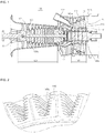
FIG. 2 is a partial perspective view of a rotor according to an embodiment of the present invention;
(It appears that a plurality of trapezoidal areas defined by dotted lines represent theretainer 145. If it is correct, it is better to include the numeral reference 145). -
FIG. 3 is a cross-sectional view of a combined part of turbine blades and a rotor of a turbine unit according to an embodiment of the present invention; and -
FIG. 4 is a rear view of a retainer according to an embodiment of the present invention. - Hereinafter, a turbine according to an embodiment of the present invention will be described with reference to the attached drawings.
- Referring to
FIGS. 1 through 4 , agas turbine 100 according to an embodiment of the present invention includes acompressor unit 120, acombustor unit 130, and aturbine unit 140. - The
compressor unit 120 is disposed at an upstream side based on a flow of air and compresses air supplied from the outside. Thecompressor unit 120 includes a plurality ofcompressor rotor discs 121. The plurality ofcompressor rotor discs 121 are coupled to one another by acentral tie rod 122 in an axial direction. - The
compressor rotor discs 121 are aligned along the axial direction while thetie rod 122 passes through the center of thecompressor rotor discs 121. - A plurality of
blades 123 are coupled to an outer circumferential surface of thecompressor rotor discs 121 in a radial direction. Adovetail 123a is provided at one end of each of theblades 123 and is coupled to each of thecompressor rotor discs 121. - The
tie rod 122 is disposed to pass through the center of the plurality ofcompressor rotor discs 121, and a downstream end of thetie rod 122 is inserted into and fixed to atorque tube 144 that transfers driving force of theturbine unit 140 to thecompressor unit 120. - The
compressor unit 120 rotates theblades 123 due to the driving force of theturbine unit 140, compresses outside air, and supplies the compressed outside air to thedownstream combustor unit 130. - The
combustor unit 130 includes one or a plurality of combustors and a fuel nozzle that injects fuel into the one or the plurality of combustors. - A plurality of combustors are arranged in a casing having a cell shape. Each of the plurality of combustors includes a combustion unit that combusts the fuel to generate high-temperature compressed gas, and a transition piece that guides the high-temperature operating gas generated in the combustion unit to the
turbine unit 140. - When the fuel and the compressed gas supplied from the
compressor unit 120 are supplied to the plurality of combustors of thecombustor unit 130, the fuel and the compressed air are combusted inside the combustors, and operating gas generated after combustion passes through the transition piece and is supplied to thedownstream turbine unit 140. - The
turbine unit 140 includes acasing 141, arotor 142, arotating blade 143, thetorque tube 144, aretainer 145, and a fixedblade 149. - The
casing 141 includes agas inlet 141a through which the operating gas supplied from thecombustor unit 130 is introduced and that is formed at one side of thecasing 141, and agas outlet 141b through which the operating gas after therotating blade 143 rotates, is discharged and that is formed at the other side of thecasing 141. A diffuser may be provided at thegas outlet 141b so as to smoothly discharge the operating gas. Also, a gas flow space in which the operating gas flows, is formed inside thecasing 141. - The
torque tube 144 is rotatably disposed in the center of the gas flow space inside thecasing 141. Thetorque tube 144 has a hollow tubular shape, and an upstream end of thetorque tube 144 is coupled to thetie rod 122, and a downstream end of thetorque tube 144 is coupled to therotor 142. - A plurality of rotating
blades 143 are mounted on an outer circumferential surface of therotor 142. Each of the rotatingblades 143 includes adovetail 143a formed at an end of therotor 142. Thedovetail 143a is slidably inserted into and coupled to acoupling groove 142a formed in the outer circumferential surface of therotor 142. Thedovetail 143a has a fir tree shape, and thecoupling groove 142a has a shape corresponding to the fir tree shape of thedovetail 143a. - A pair of
retainers 145 are mounted on both sides of thedovetail 143a of each of the rotatingblades 143 inserted into therotor 142. - Each of the pair of
retainers 145 includes aretainer frame 146 and afixing unit 150. - The
retainer frame 146 has a plate shape, and aninside chamber 148 in which cooled air may be accommodated, is formed in a surface of theretainer frame 146 facing therotating blade 143. Theretainer frame 146 is disposed at one side of therotating blade 143 and therotor 142, and forms theinside chamber 148 into which the cooled air for cooling thedovetail 143a of therotating blade 143 and therotor 142 is introduced. - In addition, the
inside chamber 148 is divided into three, i.e., first throughthird cooling chambers retainer frame 146. In the current embodiment, theinside chamber 148 is divided into three cooling chambers. However, the number of cooling chambers is not limited thereto, and theinside chamber 148 may be divided into a plurality of cooling chambers according to design conditions. - The
barrier wall 147 includes a plurality of barrier wall members spaced apart from one another in the radial direction of therotor 142 and forms the plurality of coolingchambers inside chamber 148 in the radial direction of therotor 142. As theinside chamber 148 is divided into the plurality of coolingchambers rotor 142 by means of the plurality of barrier wall members, the cooled air is delayed from flowing to the radial outside of therotor 142 and flows from the inside to the outside of eachrotating blade 143 sequentially so that the cooling efficiency of therotor 142 and therotating blades 143 can be improved. - Referring to
FIG. 4 , first andsecond communication holes second communication holes chambers - Referring to
FIG. 3 , a cooledair flow path 170 that supplies the cooled air into thecoupling groove 142a, is formed at one side of thecoupling groove 142a of therotor 142. The cooled air supplied via the cooledair flow path 170 may cool thedovetail 143a of therotating blade 143. In addition, the cooledair flow path 170 may extend between therotor 142 and therotating blade 143, and the extending cooledair flow path 170 may communicate with theinside chamber 148 of eachretainer 145. - Thus, the cooled air supplied via the cooled
air flow path 170 is supplied into thefirst cooling chamber 148a that is the innermost chamber of theinside chamber 148 of theretainer 145, in the radial direction of therotor 142. - The cooled air supplied into the
first cooling chamber 148a cools the innermost part of thedovetail 143a and therotor 142 sufficiently and then is transferred to thesecond cooling chamber 148b through thefirst communication hole 147a. The cooled air supplied to thesecond cooling chamber 148b also cools thedovetail 143a of the adjacentrotating blade 143 and therotor 142 and then is transferred to thethird cooling chamber 148c through thesecond communication hole 147b. - In this case, the
first communication hole 147a and thesecond communication hole 147b are formed in crossing positions. Thus, the cooled air supplied through thefirst communication hole 147a is delayed from flowing into thethird cooling chamber 148c through thesecond communication hole 147b so that the cooled air in thesecond cooling chamber 148b may cool thedovetail 143a of therotating blade 143 and therotor 142. - In a retainer for a gas turbine blade, a turbine unit and a gas turbine using the same according to an embodiment of the present invention, the flow of cooled air that flows in a cooling space formed at one side of a rotating blade and a rotor is controlled so that the cooled air can flow from the inside to the outside of the rotating blade sequentially and thus the cooling efficiency of the rotating blade and the rotor can be improved.
- As described above, the structure of a retainer for supporting blades is improved so that the cooling efficiency of the blades and the rotor can be improved.
- In addition, according to the present invention, a cooling space formed in a rear surface of the retainer is divided into a plurality of parts in a radial direction so that cooled air can be sequentially moved to the radial outside of the rotor. Thus, cooling of a rotating blade is smoothly performed so that the durability of the blades can be improved.
- While the present invention has been particularly shown and described with reference to exemplary embodiments thereof, it will be understood by those of ordinary skill in the art that various changes in form and details may be made therein without departing from the spirit and scope of the present invention as defined by the following claims.
Claims (15)
- A retainer for a gas turbine blade, which inhibits deviation of a rotating blade mounted on a rotor of a gas turbine, the retainer comprising:a retainer frame disposed at one side of the rotating blade and configured to form an inside chamber through which cooled air is introduced, between the retainer frame and the rotating blade;a barrier wall formed between the retainer frame and the rotating blade and configured to divide the inside chamber into a plurality of cooling chambers; anda fixing unit disposed at one side of the retainer frame and configured to fix the retainer frame to the rotor.
- The retainer of claim 1, wherein a cooled air flow path is formed between the rotating blade and the rotor, the inside chamber and the cooled air flow path communicate with each other, and the cooled air is supplied into the inside chamber via the cooled airflow path.
- The retainer of claim 1, wherein one end of the rotating blade has a fir tree shape.
- The retainer of claim 1, wherein the retainer frame is formed at both sides of the rotating blade.
- The retainer of claim 1, wherein the barrier wall comprises a plurality of barrier wall members spaced apart from one another in a radial direction of the rotor.
- The retainer of claim 5, wherein communication holes are formed in the plurality of barrier wall members so that the plurality of cooling chambers communicate with one another through the communication holes.
- The retainer of claim 6, wherein the communication holes formed in the barrier wall members are formed to cross other communication holes formed in an adjacent barrier wall member.
- A turbine unit comprising:a casing comprising a gas inlet formed at one side thereof and a gas outlet formed at the other side thereof, the casing configured to form a gas flow space inside thereof;a torque tube rotatably mounted in the gas flow space inside the casing;a rotor coupled to the torque tube and rotating together with the torque tube;a rotating blade mounted on the rotor;a retainer comprising a retainer frame disposed at one side of the rotating blade and configured to form an inside chamber through which cooled air is introduced between the retainer frame and the rotating blade, a barrier wall formed between the retainer frame and the rotating blade and configured to divide the inside chamber into a plurality of cooling chambers, and a fixing unit disposed at one side of the retainer frame and configured to fix the retainer frame to the rotor; anda fixed blade formed at an inner wall of the casing.
- The turbine unit of claim 8, wherein a cooled air flow path is formed between the rotating blade and the rotor, the inside chamber and the cooled air flow path communicate with each other, and the cooled air is supplied into the inside chamber via the cooled air flow path.
- The turbine unit of claim 8, wherein the barrier wall comprises a plurality of barrier wall members spaced apart from one another in a radial direction of the rotor.
- The turbine unit of claim 10, wherein communication holes are formed in the plurality of barrier wall members so that the plurality of cooling chambers communicate with one another through the communication holes.
- The turbine unit of claim 13, wherein the communication holes formed in the barrier wall members are formed to cross other communication holes formed in an adjacent barrier wall member.
- A gas turbine comprising:a compressor unit configured to compress air supplied from the outside;a combustor unit configured to combust the compressed air supplied from the compressor unit and a fuel so as to generate an operating gas; anda turbine unit comprising a casing comprising a gas inlet formed at one side thereof and a gas outlet formed at the other side thereof, the casing configured to form a gas flow space inside thereof, a torque tube rotatably mounted in the gas flow space inside the casing, a rotor coupled to the torque tube and rotating together with the torque tube, a rotating blade mounted on the rotor, a retainer comprising a retainer frame disposed at one side of the rotating blade and configured to form an inside chamber through which cooled air is introduced between the retainer frame and the rotating blade, a barrier wall formed between the retainer frame and the rotating blade and configured to divide the inside chamber into a plurality of cooling chambers, and a fixing unit disposed at one side of the retainer frame and configured to fix the retainer frame to the rotor, and a fixed blade formed at an inner wall of the casing.
- The gas turbine of claim 13, wherein the barrier wall comprises a plurality of barrier wall members spaced apart from one another in a radial direction of the rotor.
- The gas turbine of claim 14, wherein communication holes are formed in the plurality of barrier wall members so that the plurality of cooling chambers communicate with one another through the communication holes, and the communication holes formed in the barrier wall members are formed to cross other communication holes formed in an adjacent barrier wall member.
Applications Claiming Priority (1)
| Application Number | Priority Date | Filing Date | Title |
|---|---|---|---|
| KR1020170046874A KR20180114765A (en) | 2017-04-11 | 2017-04-11 | Retainer for gas turbine blade, turbine unit and gas turbine using the same |
Publications (2)
| Publication Number | Publication Date |
|---|---|
| EP3388635A1 true EP3388635A1 (en) | 2018-10-17 |
| EP3388635B1 EP3388635B1 (en) | 2022-03-02 |
Family
ID=60661848
Family Applications (1)
| Application Number | Title | Priority Date | Filing Date |
|---|---|---|---|
| EP17206562.5A Active EP3388635B1 (en) | 2017-04-11 | 2017-12-12 | Retainer for a rotating blade, corresponding turbine unit and gas turbine |
Country Status (4)
| Country | Link |
|---|---|
| US (1) | US10648350B2 (en) |
| EP (1) | EP3388635B1 (en) |
| JP (1) | JP6534724B2 (en) |
| KR (1) | KR20180114765A (en) |
Cited By (1)
| Publication number | Priority date | Publication date | Assignee | Title |
|---|---|---|---|---|
| EP3456925A1 (en) * | 2017-09-13 | 2019-03-20 | Doosan Heavy Industries & Construction Co., Ltd | Structure for cooling turbine blades, corresponding turbine and gas turbine |
Citations (6)
| Publication number | Priority date | Publication date | Assignee | Title |
|---|---|---|---|---|
| US6416282B1 (en) * | 1999-10-18 | 2002-07-09 | Alstom | Rotor for a gas turbine |
| GB2435909A (en) * | 2006-03-07 | 2007-09-12 | Rolls Royce Plc | Turbine blade arrangement |
| EP2009236A2 (en) * | 2007-06-27 | 2008-12-31 | United Technologies Corporation | A sideplate for a turbine rotor, corresponding turbine rotor and gas turbine engine |
| EP2236759A1 (en) * | 2009-03-27 | 2010-10-06 | Siemens Aktiengesellschaft | Rotor blade system |
| US20110129342A1 (en) * | 2009-11-30 | 2011-06-02 | Honeywell International Inc. | Turbine assemblies with impingement cooling |
| EP3070268A2 (en) * | 2015-03-20 | 2016-09-21 | Rolls-Royce plc | A bladed rotor arrangement and a lock plate for a bladed rotor arrangement and corresponding method of manufacturing |
Family Cites Families (14)
| Publication number | Priority date | Publication date | Assignee | Title |
|---|---|---|---|---|
| JPS60209603A (en) * | 1984-04-02 | 1985-10-22 | Hitachi Ltd | Rotor of turbo-machine |
| JP3652780B2 (en) * | 1996-04-08 | 2005-05-25 | 三菱重工業株式会社 | Turbine cooling system |
| GB2409240B (en) * | 2003-12-18 | 2007-04-11 | Rolls Royce Plc | A gas turbine rotor |
| EP1944471B1 (en) * | 2007-01-09 | 2009-09-02 | Siemens Aktiengesellschaft | Axial rotor section for a rotor in a turbine |
| EP2146055B2 (en) * | 2008-07-17 | 2022-01-19 | Ansaldo Energia S.P.A. | Sealing element for a gas turbine, a gas turbine including said sealing element and method for cooling said sealing element |
| US8206119B2 (en) * | 2009-02-05 | 2012-06-26 | General Electric Company | Turbine coverplate systems |
| US8696320B2 (en) * | 2009-03-12 | 2014-04-15 | General Electric Company | Gas turbine having seal assembly with coverplate and seal |
| JP5901381B2 (en) | 2012-03-26 | 2016-04-06 | Kyb株式会社 | Construction machine control equipment |
| CN104285040B (en) * | 2012-05-08 | 2016-09-07 | 西门子公司 | Axial rotor segment and turbine rotor blade for gas turbine |
| US9605552B2 (en) * | 2013-06-10 | 2017-03-28 | General Electric Company | Non-integral segmented angel-wing seal |
| GB201417039D0 (en) * | 2014-09-26 | 2014-11-12 | Rolls Royce Plc | A bladed rotor arrangement and a lock plate for a bladed rotor arrangement |
| GB201417038D0 (en) * | 2014-09-26 | 2014-11-12 | Rolls Royce Plc | A bladed rotor arrangement |
| KR101624054B1 (en) * | 2014-11-21 | 2016-05-24 | 두산중공업 주식회사 | Gas turbine with a plurality of tie rods and assembling method thoreof |
| DE102015116935A1 (en) * | 2015-10-06 | 2017-04-06 | Rolls-Royce Deutschland Ltd & Co Kg | Safety device for axially securing a blade and rotor device with such a securing device |
-
2017
- 2017-04-11 KR KR1020170046874A patent/KR20180114765A/en active Application Filing
- 2017-12-08 JP JP2017235845A patent/JP6534724B2/en active Active
- 2017-12-12 EP EP17206562.5A patent/EP3388635B1/en active Active
- 2017-12-14 US US15/842,294 patent/US10648350B2/en active Active
Patent Citations (6)
| Publication number | Priority date | Publication date | Assignee | Title |
|---|---|---|---|---|
| US6416282B1 (en) * | 1999-10-18 | 2002-07-09 | Alstom | Rotor for a gas turbine |
| GB2435909A (en) * | 2006-03-07 | 2007-09-12 | Rolls Royce Plc | Turbine blade arrangement |
| EP2009236A2 (en) * | 2007-06-27 | 2008-12-31 | United Technologies Corporation | A sideplate for a turbine rotor, corresponding turbine rotor and gas turbine engine |
| EP2236759A1 (en) * | 2009-03-27 | 2010-10-06 | Siemens Aktiengesellschaft | Rotor blade system |
| US20110129342A1 (en) * | 2009-11-30 | 2011-06-02 | Honeywell International Inc. | Turbine assemblies with impingement cooling |
| EP3070268A2 (en) * | 2015-03-20 | 2016-09-21 | Rolls-Royce plc | A bladed rotor arrangement and a lock plate for a bladed rotor arrangement and corresponding method of manufacturing |
Cited By (1)
| Publication number | Priority date | Publication date | Assignee | Title |
|---|---|---|---|---|
| EP3456925A1 (en) * | 2017-09-13 | 2019-03-20 | Doosan Heavy Industries & Construction Co., Ltd | Structure for cooling turbine blades, corresponding turbine and gas turbine |
Also Published As
| Publication number | Publication date |
|---|---|
| US10648350B2 (en) | 2020-05-12 |
| JP2018178992A (en) | 2018-11-15 |
| KR20180114765A (en) | 2018-10-19 |
| US20180291751A1 (en) | 2018-10-11 |
| EP3388635B1 (en) | 2022-03-02 |
| JP6534724B2 (en) | 2019-06-26 |
Similar Documents
| Publication | Publication Date | Title |
|---|---|---|
| CN111058901B (en) | Turbine stator blade, turbine rotor blade and gas turbine comprising same | |
| KR20200037691A (en) | Turbine blade having cooling hole at winglet and gas turbine comprising the same | |
| KR102164620B1 (en) | Combustor and gas turbine including the same | |
| KR101997979B1 (en) | Blade airfoil, turbine and gas turbine comprising the same | |
| JP2010276022A (en) | Turbomachine compressor wheel member | |
| EP3388635A1 (en) | Retainer for a gas turbine blade, corresponding turbine unit and gas turbine | |
| US11149557B2 (en) | Turbine vane, ring segment, and gas turbine including the same | |
| US10947862B2 (en) | Blade ring segment for turbine section, turbine section having the same, and gas turbine having the turbine section | |
| KR102510535B1 (en) | Ring segment and turbo-machine comprising the same | |
| KR102187958B1 (en) | blade, turbine and gas turbine comprising it, blade forming value | |
| KR102314661B1 (en) | Apparatus for cooling liner, combustor and gas turbine comprising the same | |
| WO2020240970A1 (en) | Tail pipe, combustor, gas turbine, and gas turbine equipment | |
| US10837292B2 (en) | Turbine blade with cooling structure, turbine including same turbine blade, and gas turbine including same turbine | |
| KR102223117B1 (en) | Transition piece and combustor and gas turbine that comprising the same | |
| KR102153064B1 (en) | Turbine blade and gas turbine having the same | |
| KR101955116B1 (en) | Turbine vane, turbine and gas turbine comprising the same | |
| KR102159681B1 (en) | Retainer for gas turbine blade, turbine unit and gas turbine using the same | |
| KR102183194B1 (en) | Gas turbine including an external cooling system and cooling method thereof | |
| KR102510537B1 (en) | Ring segment and turbo-machine comprising the same | |
| KR102162969B1 (en) | Turbine blade and gas turbine comprising the same | |
| KR20190041702A (en) | Structure for combining throttle plate of bucket, rotor and gas turbine | |
| KR102219297B1 (en) | blade, turbine and gas turbine comprising it, blade forming value | |
| KR102248037B1 (en) | Turbine blade having magnetic damper | |
| KR102025148B1 (en) | Gas turbine including pre-swirl system | |
| KR20240095997A (en) | Ring segment and gas turbine comprising it |
Legal Events
| Date | Code | Title | Description |
|---|---|---|---|
| PUAI | Public reference made under article 153(3) epc to a published international application that has entered the european phase |
Free format text: ORIGINAL CODE: 0009012 |
|
| STAA | Information on the status of an ep patent application or granted ep patent |
Free format text: STATUS: REQUEST FOR EXAMINATION WAS MADE |
|
| 17P | Request for examination filed |
Effective date: 20171212 |
|
| AK | Designated contracting states |
Kind code of ref document: A1 Designated state(s): AL AT BE BG CH CY CZ DE DK EE ES FI FR GB GR HR HU IE IS IT LI LT LU LV MC MK MT NL NO PL PT RO RS SE SI SK SM TR |
|
| AX | Request for extension of the european patent |
Extension state: BA ME |
|
| STAA | Information on the status of an ep patent application or granted ep patent |
Free format text: STATUS: EXAMINATION IS IN PROGRESS |
|
| 17Q | First examination report despatched |
Effective date: 20210218 |
|
| RIC1 | Information provided on ipc code assigned before grant |
Ipc: F01D 5/08 20060101ALN20210802BHEP Ipc: F01D 5/30 20060101AFI20210802BHEP |
|
| GRAP | Despatch of communication of intention to grant a patent |
Free format text: ORIGINAL CODE: EPIDOSNIGR1 |
|
| STAA | Information on the status of an ep patent application or granted ep patent |
Free format text: STATUS: GRANT OF PATENT IS INTENDED |
|
| INTG | Intention to grant announced |
Effective date: 20210914 |
|
| GRAS | Grant fee paid |
Free format text: ORIGINAL CODE: EPIDOSNIGR3 |
|
| GRAA | (expected) grant |
Free format text: ORIGINAL CODE: 0009210 |
|
| STAA | Information on the status of an ep patent application or granted ep patent |
Free format text: STATUS: THE PATENT HAS BEEN GRANTED |
|
| AK | Designated contracting states |
Kind code of ref document: B1 Designated state(s): AL AT BE BG CH CY CZ DE DK EE ES FI FR GB GR HR HU IE IS IT LI LT LU LV MC MK MT NL NO PL PT RO RS SE SI SK SM TR |
|
| REG | Reference to a national code |
Ref country code: GB Ref legal event code: FG4D |
|
| REG | Reference to a national code |
Ref country code: CH Ref legal event code: EP Ref country code: AT Ref legal event code: REF Ref document number: 1472384 Country of ref document: AT Kind code of ref document: T Effective date: 20220315 |
|
| REG | Reference to a national code |
Ref country code: DE Ref legal event code: R096 Ref document number: 602017053972 Country of ref document: DE |
|
| REG | Reference to a national code |
Ref country code: IE Ref legal event code: FG4D |
|
| REG | Reference to a national code |
Ref country code: LT Ref legal event code: MG9D |
|
| REG | Reference to a national code |
Ref country code: NL Ref legal event code: MP Effective date: 20220302 |
|
| PG25 | Lapsed in a contracting state [announced via postgrant information from national office to epo] |
Ref country code: SE Free format text: LAPSE BECAUSE OF FAILURE TO SUBMIT A TRANSLATION OF THE DESCRIPTION OR TO PAY THE FEE WITHIN THE PRESCRIBED TIME-LIMIT Effective date: 20220302 Ref country code: RS Free format text: LAPSE BECAUSE OF FAILURE TO SUBMIT A TRANSLATION OF THE DESCRIPTION OR TO PAY THE FEE WITHIN THE PRESCRIBED TIME-LIMIT Effective date: 20220302 Ref country code: NO Free format text: LAPSE BECAUSE OF FAILURE TO SUBMIT A TRANSLATION OF THE DESCRIPTION OR TO PAY THE FEE WITHIN THE PRESCRIBED TIME-LIMIT Effective date: 20220602 Ref country code: LT Free format text: LAPSE BECAUSE OF FAILURE TO SUBMIT A TRANSLATION OF THE DESCRIPTION OR TO PAY THE FEE WITHIN THE PRESCRIBED TIME-LIMIT Effective date: 20220302 Ref country code: HR Free format text: LAPSE BECAUSE OF FAILURE TO SUBMIT A TRANSLATION OF THE DESCRIPTION OR TO PAY THE FEE WITHIN THE PRESCRIBED TIME-LIMIT Effective date: 20220302 Ref country code: ES Free format text: LAPSE BECAUSE OF FAILURE TO SUBMIT A TRANSLATION OF THE DESCRIPTION OR TO PAY THE FEE WITHIN THE PRESCRIBED TIME-LIMIT Effective date: 20220302 Ref country code: BG Free format text: LAPSE BECAUSE OF FAILURE TO SUBMIT A TRANSLATION OF THE DESCRIPTION OR TO PAY THE FEE WITHIN THE PRESCRIBED TIME-LIMIT Effective date: 20220602 |
|
| REG | Reference to a national code |
Ref country code: AT Ref legal event code: MK05 Ref document number: 1472384 Country of ref document: AT Kind code of ref document: T Effective date: 20220302 |
|
| PG25 | Lapsed in a contracting state [announced via postgrant information from national office to epo] |
Ref country code: PL Free format text: LAPSE BECAUSE OF FAILURE TO SUBMIT A TRANSLATION OF THE DESCRIPTION OR TO PAY THE FEE WITHIN THE PRESCRIBED TIME-LIMIT Effective date: 20220302 Ref country code: LV Free format text: LAPSE BECAUSE OF FAILURE TO SUBMIT A TRANSLATION OF THE DESCRIPTION OR TO PAY THE FEE WITHIN THE PRESCRIBED TIME-LIMIT Effective date: 20220302 Ref country code: GR Free format text: LAPSE BECAUSE OF FAILURE TO SUBMIT A TRANSLATION OF THE DESCRIPTION OR TO PAY THE FEE WITHIN THE PRESCRIBED TIME-LIMIT Effective date: 20220603 Ref country code: FI Free format text: LAPSE BECAUSE OF FAILURE TO SUBMIT A TRANSLATION OF THE DESCRIPTION OR TO PAY THE FEE WITHIN THE PRESCRIBED TIME-LIMIT Effective date: 20220302 |
|
| PG25 | Lapsed in a contracting state [announced via postgrant information from national office to epo] |
Ref country code: NL Free format text: LAPSE BECAUSE OF FAILURE TO SUBMIT A TRANSLATION OF THE DESCRIPTION OR TO PAY THE FEE WITHIN THE PRESCRIBED TIME-LIMIT Effective date: 20220302 |
|
| PG25 | Lapsed in a contracting state [announced via postgrant information from national office to epo] |
Ref country code: SM Free format text: LAPSE BECAUSE OF FAILURE TO SUBMIT A TRANSLATION OF THE DESCRIPTION OR TO PAY THE FEE WITHIN THE PRESCRIBED TIME-LIMIT Effective date: 20220302 Ref country code: SK Free format text: LAPSE BECAUSE OF FAILURE TO SUBMIT A TRANSLATION OF THE DESCRIPTION OR TO PAY THE FEE WITHIN THE PRESCRIBED TIME-LIMIT Effective date: 20220302 Ref country code: RO Free format text: LAPSE BECAUSE OF FAILURE TO SUBMIT A TRANSLATION OF THE DESCRIPTION OR TO PAY THE FEE WITHIN THE PRESCRIBED TIME-LIMIT Effective date: 20220302 Ref country code: PT Free format text: LAPSE BECAUSE OF FAILURE TO SUBMIT A TRANSLATION OF THE DESCRIPTION OR TO PAY THE FEE WITHIN THE PRESCRIBED TIME-LIMIT Effective date: 20220704 Ref country code: EE Free format text: LAPSE BECAUSE OF FAILURE TO SUBMIT A TRANSLATION OF THE DESCRIPTION OR TO PAY THE FEE WITHIN THE PRESCRIBED TIME-LIMIT Effective date: 20220302 Ref country code: CZ Free format text: LAPSE BECAUSE OF FAILURE TO SUBMIT A TRANSLATION OF THE DESCRIPTION OR TO PAY THE FEE WITHIN THE PRESCRIBED TIME-LIMIT Effective date: 20220302 Ref country code: AT Free format text: LAPSE BECAUSE OF FAILURE TO SUBMIT A TRANSLATION OF THE DESCRIPTION OR TO PAY THE FEE WITHIN THE PRESCRIBED TIME-LIMIT Effective date: 20220302 |
|
| PG25 | Lapsed in a contracting state [announced via postgrant information from national office to epo] |
Ref country code: IS Free format text: LAPSE BECAUSE OF FAILURE TO SUBMIT A TRANSLATION OF THE DESCRIPTION OR TO PAY THE FEE WITHIN THE PRESCRIBED TIME-LIMIT Effective date: 20220702 Ref country code: AL Free format text: LAPSE BECAUSE OF FAILURE TO SUBMIT A TRANSLATION OF THE DESCRIPTION OR TO PAY THE FEE WITHIN THE PRESCRIBED TIME-LIMIT Effective date: 20220302 |
|
| REG | Reference to a national code |
Ref country code: DE Ref legal event code: R097 Ref document number: 602017053972 Country of ref document: DE |
|
| PLBE | No opposition filed within time limit |
Free format text: ORIGINAL CODE: 0009261 |
|
| STAA | Information on the status of an ep patent application or granted ep patent |
Free format text: STATUS: NO OPPOSITION FILED WITHIN TIME LIMIT |
|
| PG25 | Lapsed in a contracting state [announced via postgrant information from national office to epo] |
Ref country code: DK Free format text: LAPSE BECAUSE OF FAILURE TO SUBMIT A TRANSLATION OF THE DESCRIPTION OR TO PAY THE FEE WITHIN THE PRESCRIBED TIME-LIMIT Effective date: 20220302 |
|
| 26N | No opposition filed |
Effective date: 20221205 |
|
| PG25 | Lapsed in a contracting state [announced via postgrant information from national office to epo] |
Ref country code: SI Free format text: LAPSE BECAUSE OF FAILURE TO SUBMIT A TRANSLATION OF THE DESCRIPTION OR TO PAY THE FEE WITHIN THE PRESCRIBED TIME-LIMIT Effective date: 20220302 |
|
| PG25 | Lapsed in a contracting state [announced via postgrant information from national office to epo] |
Ref country code: IT Free format text: LAPSE BECAUSE OF FAILURE TO SUBMIT A TRANSLATION OF THE DESCRIPTION OR TO PAY THE FEE WITHIN THE PRESCRIBED TIME-LIMIT Effective date: 20220302 |
|
| REG | Reference to a national code |
Ref country code: CH Ref legal event code: PL |
|
| GBPC | Gb: european patent ceased through non-payment of renewal fee |
Effective date: 20221212 |
|
| REG | Reference to a national code |
Ref country code: BE Ref legal event code: MM Effective date: 20221231 |
|
| PG25 | Lapsed in a contracting state [announced via postgrant information from national office to epo] |
Ref country code: LU Free format text: LAPSE BECAUSE OF NON-PAYMENT OF DUE FEES Effective date: 20221212 |
|
| PG25 | Lapsed in a contracting state [announced via postgrant information from national office to epo] |
Ref country code: LI Free format text: LAPSE BECAUSE OF NON-PAYMENT OF DUE FEES Effective date: 20221231 Ref country code: IE Free format text: LAPSE BECAUSE OF NON-PAYMENT OF DUE FEES Effective date: 20221212 Ref country code: GB Free format text: LAPSE BECAUSE OF NON-PAYMENT OF DUE FEES Effective date: 20221212 Ref country code: CH Free format text: LAPSE BECAUSE OF NON-PAYMENT OF DUE FEES Effective date: 20221231 |
|
| PG25 | Lapsed in a contracting state [announced via postgrant information from national office to epo] |
Ref country code: FR Free format text: LAPSE BECAUSE OF NON-PAYMENT OF DUE FEES Effective date: 20221231 Ref country code: BE Free format text: LAPSE BECAUSE OF NON-PAYMENT OF DUE FEES Effective date: 20221231 |
|
| PGFP | Annual fee paid to national office [announced via postgrant information from national office to epo] |
Ref country code: DE Payment date: 20231017 Year of fee payment: 7 |
|
| PG25 | Lapsed in a contracting state [announced via postgrant information from national office to epo] |
Ref country code: HU Free format text: LAPSE BECAUSE OF FAILURE TO SUBMIT A TRANSLATION OF THE DESCRIPTION OR TO PAY THE FEE WITHIN THE PRESCRIBED TIME-LIMIT; INVALID AB INITIO Effective date: 20171212 |
|
| PG25 | Lapsed in a contracting state [announced via postgrant information from national office to epo] |
Ref country code: CY Free format text: LAPSE BECAUSE OF FAILURE TO SUBMIT A TRANSLATION OF THE DESCRIPTION OR TO PAY THE FEE WITHIN THE PRESCRIBED TIME-LIMIT Effective date: 20220302 |
|
| PG25 | Lapsed in a contracting state [announced via postgrant information from national office to epo] |
Ref country code: MK Free format text: LAPSE BECAUSE OF FAILURE TO SUBMIT A TRANSLATION OF THE DESCRIPTION OR TO PAY THE FEE WITHIN THE PRESCRIBED TIME-LIMIT Effective date: 20220302 |
|
| PG25 | Lapsed in a contracting state [announced via postgrant information from national office to epo] |
Ref country code: MC Free format text: LAPSE BECAUSE OF FAILURE TO SUBMIT A TRANSLATION OF THE DESCRIPTION OR TO PAY THE FEE WITHIN THE PRESCRIBED TIME-LIMIT Effective date: 20220302 |
|
| PG25 | Lapsed in a contracting state [announced via postgrant information from national office to epo] |
Ref country code: TR Free format text: LAPSE BECAUSE OF FAILURE TO SUBMIT A TRANSLATION OF THE DESCRIPTION OR TO PAY THE FEE WITHIN THE PRESCRIBED TIME-LIMIT Effective date: 20220302 Ref country code: MC Free format text: LAPSE BECAUSE OF FAILURE TO SUBMIT A TRANSLATION OF THE DESCRIPTION OR TO PAY THE FEE WITHIN THE PRESCRIBED TIME-LIMIT Effective date: 20220302 |