EP3388629B1 - Turbine vane - Google Patents
Turbine vane Download PDFInfo
- Publication number
- EP3388629B1 EP3388629B1 EP18152435.6A EP18152435A EP3388629B1 EP 3388629 B1 EP3388629 B1 EP 3388629B1 EP 18152435 A EP18152435 A EP 18152435A EP 3388629 B1 EP3388629 B1 EP 3388629B1
- Authority
- EP
- European Patent Office
- Prior art keywords
- cooling
- turbine
- airfoil
- cooling chamber
- air
- Prior art date
- Legal status (The legal status is an assumption and is not a legal conclusion. Google has not performed a legal analysis and makes no representation as to the accuracy of the status listed.)
- Active
Links
- 238000001816 cooling Methods 0.000 claims description 122
- 239000000446 fuel Substances 0.000 claims description 5
- 238000002485 combustion reaction Methods 0.000 description 4
- 238000010586 diagram Methods 0.000 description 4
- 238000004088 simulation Methods 0.000 description 4
- 238000005192 partition Methods 0.000 description 3
- 230000001419 dependent effect Effects 0.000 description 2
- 239000012530 fluid Substances 0.000 description 2
- 238000000034 method Methods 0.000 description 2
- 238000012986 modification Methods 0.000 description 2
- 230000004048 modification Effects 0.000 description 2
- 230000008646 thermal stress Effects 0.000 description 2
- 238000007792 addition Methods 0.000 description 1
- 238000010276 construction Methods 0.000 description 1
- 239000012809 cooling fluid Substances 0.000 description 1
- 230000005611 electricity Effects 0.000 description 1
- 238000005516 engineering process Methods 0.000 description 1
- 230000003137 locomotive effect Effects 0.000 description 1
- 230000035515 penetration Effects 0.000 description 1
- 238000006467 substitution reaction Methods 0.000 description 1
Images


Classifications
-
- F—MECHANICAL ENGINEERING; LIGHTING; HEATING; WEAPONS; BLASTING
- F01—MACHINES OR ENGINES IN GENERAL; ENGINE PLANTS IN GENERAL; STEAM ENGINES
- F01D—NON-POSITIVE DISPLACEMENT MACHINES OR ENGINES, e.g. STEAM TURBINES
- F01D5/00—Blades; Blade-carrying members; Heating, heat-insulating, cooling or antivibration means on the blades or the members
- F01D5/12—Blades
-
- F—MECHANICAL ENGINEERING; LIGHTING; HEATING; WEAPONS; BLASTING
- F01—MACHINES OR ENGINES IN GENERAL; ENGINE PLANTS IN GENERAL; STEAM ENGINES
- F01D—NON-POSITIVE DISPLACEMENT MACHINES OR ENGINES, e.g. STEAM TURBINES
- F01D9/00—Stators
- F01D9/02—Nozzles; Nozzle boxes; Stator blades; Guide conduits, e.g. individual nozzles
- F01D9/04—Nozzles; Nozzle boxes; Stator blades; Guide conduits, e.g. individual nozzles forming ring or sector
- F01D9/041—Nozzles; Nozzle boxes; Stator blades; Guide conduits, e.g. individual nozzles forming ring or sector using blades
-
- F—MECHANICAL ENGINEERING; LIGHTING; HEATING; WEAPONS; BLASTING
- F01—MACHINES OR ENGINES IN GENERAL; ENGINE PLANTS IN GENERAL; STEAM ENGINES
- F01D—NON-POSITIVE DISPLACEMENT MACHINES OR ENGINES, e.g. STEAM TURBINES
- F01D25/00—Component parts, details, or accessories, not provided for in, or of interest apart from, other groups
- F01D25/08—Cooling; Heating; Heat-insulation
- F01D25/12—Cooling
-
- F—MECHANICAL ENGINEERING; LIGHTING; HEATING; WEAPONS; BLASTING
- F01—MACHINES OR ENGINES IN GENERAL; ENGINE PLANTS IN GENERAL; STEAM ENGINES
- F01D—NON-POSITIVE DISPLACEMENT MACHINES OR ENGINES, e.g. STEAM TURBINES
- F01D5/00—Blades; Blade-carrying members; Heating, heat-insulating, cooling or antivibration means on the blades or the members
- F01D5/12—Blades
- F01D5/14—Form or construction
- F01D5/18—Hollow blades, i.e. blades with cooling or heating channels or cavities; Heating, heat-insulating or cooling means on blades
- F01D5/187—Convection cooling
-
- F—MECHANICAL ENGINEERING; LIGHTING; HEATING; WEAPONS; BLASTING
- F01—MACHINES OR ENGINES IN GENERAL; ENGINE PLANTS IN GENERAL; STEAM ENGINES
- F01D—NON-POSITIVE DISPLACEMENT MACHINES OR ENGINES, e.g. STEAM TURBINES
- F01D9/00—Stators
- F01D9/06—Fluid supply conduits to nozzles or the like
- F01D9/065—Fluid supply or removal conduits traversing the working fluid flow, e.g. for lubrication-, cooling-, or sealing fluids
-
- F—MECHANICAL ENGINEERING; LIGHTING; HEATING; WEAPONS; BLASTING
- F02—COMBUSTION ENGINES; HOT-GAS OR COMBUSTION-PRODUCT ENGINE PLANTS
- F02C—GAS-TURBINE PLANTS; AIR INTAKES FOR JET-PROPULSION PLANTS; CONTROLLING FUEL SUPPLY IN AIR-BREATHING JET-PROPULSION PLANTS
- F02C3/00—Gas-turbine plants characterised by the use of combustion products as the working fluid
- F02C3/04—Gas-turbine plants characterised by the use of combustion products as the working fluid having a turbine driving a compressor
-
- F—MECHANICAL ENGINEERING; LIGHTING; HEATING; WEAPONS; BLASTING
- F02—COMBUSTION ENGINES; HOT-GAS OR COMBUSTION-PRODUCT ENGINE PLANTS
- F02C—GAS-TURBINE PLANTS; AIR INTAKES FOR JET-PROPULSION PLANTS; CONTROLLING FUEL SUPPLY IN AIR-BREATHING JET-PROPULSION PLANTS
- F02C7/00—Features, components parts, details or accessories, not provided for in, or of interest apart form groups F02C1/00 - F02C6/00; Air intakes for jet-propulsion plants
- F02C7/12—Cooling of plants
- F02C7/16—Cooling of plants characterised by cooling medium
- F02C7/18—Cooling of plants characterised by cooling medium the medium being gaseous, e.g. air
-
- F—MECHANICAL ENGINEERING; LIGHTING; HEATING; WEAPONS; BLASTING
- F05—INDEXING SCHEMES RELATING TO ENGINES OR PUMPS IN VARIOUS SUBCLASSES OF CLASSES F01-F04
- F05D—INDEXING SCHEME FOR ASPECTS RELATING TO NON-POSITIVE-DISPLACEMENT MACHINES OR ENGINES, GAS-TURBINES OR JET-PROPULSION PLANTS
- F05D2240/00—Components
- F05D2240/10—Stators
- F05D2240/12—Fluid guiding means, e.g. vanes
- F05D2240/121—Fluid guiding means, e.g. vanes related to the leading edge of a stator vane
-
- F—MECHANICAL ENGINEERING; LIGHTING; HEATING; WEAPONS; BLASTING
- F05—INDEXING SCHEMES RELATING TO ENGINES OR PUMPS IN VARIOUS SUBCLASSES OF CLASSES F01-F04
- F05D—INDEXING SCHEME FOR ASPECTS RELATING TO NON-POSITIVE-DISPLACEMENT MACHINES OR ENGINES, GAS-TURBINES OR JET-PROPULSION PLANTS
- F05D2240/00—Components
- F05D2240/10—Stators
- F05D2240/12—Fluid guiding means, e.g. vanes
- F05D2240/122—Fluid guiding means, e.g. vanes related to the trailing edge of a stator vane
-
- F—MECHANICAL ENGINEERING; LIGHTING; HEATING; WEAPONS; BLASTING
- F05—INDEXING SCHEMES RELATING TO ENGINES OR PUMPS IN VARIOUS SUBCLASSES OF CLASSES F01-F04
- F05D—INDEXING SCHEME FOR ASPECTS RELATING TO NON-POSITIVE-DISPLACEMENT MACHINES OR ENGINES, GAS-TURBINES OR JET-PROPULSION PLANTS
- F05D2240/00—Components
- F05D2240/80—Platforms for stationary or moving blades
- F05D2240/81—Cooled platforms
-
- F—MECHANICAL ENGINEERING; LIGHTING; HEATING; WEAPONS; BLASTING
- F05—INDEXING SCHEMES RELATING TO ENGINES OR PUMPS IN VARIOUS SUBCLASSES OF CLASSES F01-F04
- F05D—INDEXING SCHEME FOR ASPECTS RELATING TO NON-POSITIVE-DISPLACEMENT MACHINES OR ENGINES, GAS-TURBINES OR JET-PROPULSION PLANTS
- F05D2260/00—Function
- F05D2260/20—Heat transfer, e.g. cooling
- F05D2260/202—Heat transfer, e.g. cooling by film cooling
-
- F—MECHANICAL ENGINEERING; LIGHTING; HEATING; WEAPONS; BLASTING
- F05—INDEXING SCHEMES RELATING TO ENGINES OR PUMPS IN VARIOUS SUBCLASSES OF CLASSES F01-F04
- F05D—INDEXING SCHEME FOR ASPECTS RELATING TO NON-POSITIVE-DISPLACEMENT MACHINES OR ENGINES, GAS-TURBINES OR JET-PROPULSION PLANTS
- F05D2260/00—Function
- F05D2260/20—Heat transfer, e.g. cooling
- F05D2260/204—Heat transfer, e.g. cooling by the use of microcircuits
-
- F—MECHANICAL ENGINEERING; LIGHTING; HEATING; WEAPONS; BLASTING
- F05—INDEXING SCHEMES RELATING TO ENGINES OR PUMPS IN VARIOUS SUBCLASSES OF CLASSES F01-F04
- F05D—INDEXING SCHEME FOR ASPECTS RELATING TO NON-POSITIVE-DISPLACEMENT MACHINES OR ENGINES, GAS-TURBINES OR JET-PROPULSION PLANTS
- F05D2260/00—Function
- F05D2260/20—Heat transfer, e.g. cooling
- F05D2260/221—Improvement of heat transfer
- F05D2260/2212—Improvement of heat transfer by creating turbulence
-
- Y—GENERAL TAGGING OF NEW TECHNOLOGICAL DEVELOPMENTS; GENERAL TAGGING OF CROSS-SECTIONAL TECHNOLOGIES SPANNING OVER SEVERAL SECTIONS OF THE IPC; TECHNICAL SUBJECTS COVERED BY FORMER USPC CROSS-REFERENCE ART COLLECTIONS [XRACs] AND DIGESTS
- Y02—TECHNOLOGIES OR APPLICATIONS FOR MITIGATION OR ADAPTATION AGAINST CLIMATE CHANGE
- Y02T—CLIMATE CHANGE MITIGATION TECHNOLOGIES RELATED TO TRANSPORTATION
- Y02T50/00—Aeronautics or air transport
- Y02T50/60—Efficient propulsion technologies, e.g. for aircraft
Definitions
- the present disclosure relates to a turbine vane and a gas turbine including the same, and more particularly to a turbine vane, which is used in a gas turbine so as to reduce a temperature with fuel, combusts the mixed air, and rotates a turbine using the high temperature generated by the combustion.
- the gas turbine is used to drive a generator, an aircraft, a locomotive and the like.
- a gas turbine includes a compressor, a combustor and a turbine.
- the compressor compresses external air introduced from the outside and transfers the compressed air to the combustor.
- the air compressed in the compressor becomes high-pressure and high-temperature air.
- the combustor mixes the compressed air, introduced from the compressor, with fuel, and combusts the mixed air.
- the combusted gas resulting from the combustion is discharged to the turbine.
- the turbine is rotated by the combusted gas, thereby generating power.
- the generated power is used in various fields, such as in the generation of electricity and to drive machinery.
- EP 1 074 695 A2 discloses a method for cooling the trailing edge region of a stator vane platform.
- US 8 459 935 B1 presents turbine stator vane with endwall cooling that includes a number of impingement chambers that extend around the airfoil perpendicular to a hot gas flow over the endwall, the impingement chambers are connected by rows of near wall cooling channels offset so that impingement cooling occurs within the chambers, some of the impingement chambers are connected by resupply cooling air holes and some of the impingement chambers are connected to film cooling holes.
- EP 2 626 519 A1 presents a turbine assembly that comprises a hollow aerofoil having a cavity with an impingement tube, which is insertable inside the cavity and is used for impingement cooling of the inner surface of the cavity, and with a platform, arranged at a radial end of the hollow aerofoil.
- a cooling chamber used for cooling the platform is arranged relative to the hollow aerofoil on an opposed side of the platform and is limited at a first radial end from the platform and at an opposed radial second end from a cover plate.
- the impingement tube has a first section and at least a second section.
- EP 2 711 502 A1 presents that in a turbine vane and a gas turbine, an outer shroud is fixed to one end of a vane body formed in a hollow shape, an inner shroud is fixed to the other end thereof, and a partition plate is fixed to the inner portions of the vane body, the outer shroud, and the inner shroud, so that a cavity is formed so as to be continuous between the partition plate and the group of the vane body, the outer shroud, and the inner shroud.
- US 5 197 852 A presents a nozzle assembly for a high pressure turbine of a gas turbine engine.
- the nozzle assembly includes a series of circumferentially spaced vanes and a nozzle band.
- the nozzle band supports the vanes and includes a mounting flange extending radially from the nozzle band and adapted to be secured to the gas turbine engine.
- the nozzle band has an overhang portion axially downstream of the mounting flange.
- a pin fin bank is formed within the overhang portion for allowing cooling fluid to flow therethrough to cool the overhang portion.
- An exemplary object of the present disclosure is to provide a turbine vane and a gas turbine, which are able to suppress a rise in temperature attributable to combusted gas.
- a turbine vane is provided as defined in claim 1.
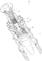
- FIG. 1 is a view schematically illustrating the internal structure of a gas turbine according to an embodiment of the present disclosure.
- the gas turbine 1 includes a compressor 10, a combustor 20 and a turbine 30.
- the compressor 10 serves to compress air introduced thereinto under high pressure and transfer the compressed air to the combustor 20.
- the compressor 10 includes a plurality of blades 11, which are radially arranged. The blades 11 are rotated using some of the power resulting from rotation of the turbine 30, and air is moved to the combustor while being compressed by virtue of the rotation of the blades 11.
- the size and mounting angle of the blades 11 may be varied depending on the mounting position.
- the air compressed in the compressor 10 is moved to the combustor 20, and is mixed with fuel and combusted through a plurality of combustion chambers 21 and fuel nozzle modules 22, which are arranged in a circular pattern.
- High-temperature combusted gas, which results from the combustion, is discharged to the turbine 30, and the turbine 30 is thus rotated by the combusted gas.
- FIG. 2 is a conceptual view illustrating the region of the turbine at which turbine vanes according to an embodiment of the present disclosure are disposed.
- the turbine 30 may be constructed such that n turbine vanes 100 (100a, 100b, and so forth) and n turbine blades 200 (200a, 200b and so forth) are alternately arranged in the axial direction of the gas turbine 1.
- High-temperature combusted gas HG rotates the turbine blades 200 while passing through the turbine vanes 100 and the turbine blades 200.
- FIG. 3 is a perspective view illustrating the turbine vane according to the invention.
- the turbine vane includes an airfoil 110 and inner and outer shrouds 120 and 130.
- Each of the inner and outer shrouds 120 and 130 is provided with a cooling chamber 140 so as to allow cooling air to flow therethrough.
- the airfoil 110 is provided with a leading edge 111 and a trailing edge 112.
- the leading edge 111 refers to a front end colliding with fluid flowing along the airfoil 110
- the trailing edge 112 refers to a rear end of the airfoil 110.
- the airfoil 110 includes a pressure side and a suction side, which extend between the leading edge 111 and the trailing edge 112. The pressure side is subjected to pressure due to the flowing fluid.
- the inner and outer shrouds 120 and 130 are positioned at opposite ends of the airfoil 110 so as to support the airfoil 110.
- the inner shroud 120 includes a platform part 122 and root parts 124 and 126
- the outer shroud 130 includes a platform part 132 and root parts 134 and 136.
- the turbine vane 100 is constructed such that the inner shroud 120 is positioned toward the rotational axis of the gas turbine 1 and the outer shroud 130 is positioned toward the outside of the gas turbine 1.
- Each of the platform parts 122 and 132 may have the shape of a plate having a flat surface facing the airfoil 110.
- the root parts 124, 126, 134 and 136 are disposed on the outer surfaces of the platform parts 122 and 132, that is, the surfaces opposite the flat surfaces facing the airfoil 110, and extend outward from the platform parts 122 and 132.
- the cooling chamber 140 may be provided at one of opposite ends of the platform part arranged in the first direction. Cooling air CG is introduced into the cooling chamber 140 in the shroud 120 or 130 so as to cool the shroud 120 or 130, and is discharged to the outside from the shroud 120 or 130 (see FIG. 2 ). Cooling air may be introduced into the inner shroud 120 from the compressor 10 through a cooling path formed in a compressor disk unit, a tie rod and a turbine disk unit 310. Furthermore, cooling air may be introduced into the outer shroud 130 through an external cooling path connected to the compressor 10 and through a turbine casing.
- Each of the platform parts 122 and 132 and the root parts 124, 126, 134 and 136 may include a plurality of cooling holes through which the outer surface thereof communicates with the inside thereof. Since cooling air on the outer surface of the platform part or the root part flows through the cooling holes in the manner of an air curtain, it is possible to cool the shrouds 120 and 130 including the platform parts 122 and 132 and the root parts 124, 126, 134 and 136 in a film-cooling manner. Since the cooling chamber 140 communicates with some of the cooling holes such that cooling air flows through the cooling chamber 140 and the cooling holes, it is possible to further improve the cooling efficiency.
- the cooling chamber 140 may be provided outside the region of the platform part 122 or 132 at which the root part 124, 126, 134 or 136 is positioned, and may be formed so as not to overlap the root part 124, 126, 134 or 136 when viewed in the thickness direction of the platform part 122 or 132. This construction is able to further improve the cooling efficiency because the root part 124, 126, 134 or 136 may be provided with the cooling holes.
- the airfoil 110 may also be provided therein with a cooling channel through which cooling air flows. It is possible to cool the airfoil 110 using the cooling air flowing through the airfoil 110. Since the cooling chamber 140 communicates with the cooling channel such that cooling air flows through the cooling chamber 140 and the cooling channel, it is possible to further improve cooling efficiency.
- the cooling air CG can flow between the cooling chamber in the inner shroud 120 and the cooling chamber in the outer shroud 130 through the cooling channel in the airfoil 110 (see FIG. 2 ).
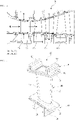
- FIGS. 4 to 9 are perspective views illustrating variations of the cooling chamber.
- the cooling chamber 140 may extend in the second direction, as shown in FIG. 4 .
- the cooling chamber 140 includes a plurality of cooling chamber segments, and connecting holes are provided between the plurality of cooling chamber segments.
- the cooling chamber 142a includes a plurality of cooling chamber segments, which are arranged in the second direction, intersecting the first direction.
- the connecting holes 142b connect the plurality of cooling chamber segments 142a in a zigzag fashion with respect to the second direction. When the connecting holes 142b are arranged in the zigzag fashion, a vortex flow is generated in the cooling air introduced into the cooling chamber 142a, which improves the efficiency of heat exchange and thus efficiently cools the shroud 120 or 130.
- the cooling chamber 143a may include a plurality of cooling chamber segments, which are arranged in a zigzag fashion with respect to the second direction intersecting the first direction and are connected to each other through connecting holes 143b.
- a vortex flow may also by generated in the cooling air introduced into the cooling chamber 143a, which improves the efficiency of heat exchange and thus efficiently cools the shroud 120 or 130.
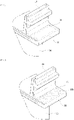
- the cooling chamber 144a includes a plurality of cooling chamber segments, which extend in the second direction intersecting the first direction and are arranged in the first direction.
- Connecting holes 144b are arranged in a zigzag fashion with respect to the first direction so as to connect the plurality of cooling chamber segments 144a to each other.
- a vortex. flow may also be generated in the cooling air introduced into the cooling chamber 144a, which improves the efficiency of heat exchange and thus efficiently cools the shroud 120 or 130.
- the cooling chamber 145a may be provided on the bottom or ceiling surface thereof with a plurality of protrusions 145b.
- FIG. 8 illustrates an embodiment in which the protrusions 145b are provided on the bottom surface of the cooling chamber 145a, but the protrusions may also be provided on the ceiling surface of the cooling chamber 145a.
- the protrusions may be arranged into circular columns connecting the bottom surface and the ceiling surface of the cooling chamber 145a.
- the protrusions 145b are illustrated in FIG. 8 as being arranged in regular rows and columns, but the protrusions 145b may also be irregularly arranged.
- the embodiment of figure 8 does not form part of the inventionas claimed.
- the cooling chamber 146a may be provided on the bottom or ceiling surface thereof with ridges and valleys 146b, which are repeatedly arranged. While the ridges and valleys 146b are illustrated in FIG. 9 as being repeatedly arranged, the ridges and valleys 146b may also be arranged in multiple rows.
- a vortex flow may also be generated in the cooling air introduced into the cooling chamber 145a or 146a, which improves the efficiency of heat exchange and thus efficiently cools the shroud 120 or 130.
- the embodiment of figure 9 does not form part of the invention as claimed.
- FIG. 10 is a conceptual view illustrating positions of the cooling chambers in the turbine vane.
- the cooling chambers 140 are formed in any one of opposite ends of the inner shroud 120 and the outer shroud 130 arranged in the first direction, and may communicate with each other through the platform parts and the airfoil so as to allow cooling air to flow therethrough.
- FIG. 11 is a conceptual diagram illustrating a simulation result of temperature variation on a turbine vane
- FIG. 12 is a conceptual diagram illustrating a simulation result of temperature variation on the turbine vane according to the embodiment of the present disclosure.
- a turbine vane which is not provided with the cooling chamber, exhibits a temperature distribution of about 490 - 1024 degrees, which indicates a temperature variation of 500 degrees or higher.
- the turbine vane according to the embodiment of the present disclosure exhibits a temperature distribution of 800 degrees or lower throughout almost the entire region thereof, which indicates a temperature variation of 300 degrees or less.
Description
- The present disclosure relates to a turbine vane and a gas turbine including the same, and more particularly to a turbine vane, which is used in a gas turbine so as to reduce a temperature with fuel, combusts the mixed air, and rotates a turbine using the high temperature generated by the combustion. The gas turbine is used to drive a generator, an aircraft, a locomotive and the like.
- Generally, a gas turbine includes a compressor, a combustor and a turbine. The compressor compresses external air introduced from the outside and transfers the compressed air to the combustor. The air compressed in the compressor becomes high-pressure and high-temperature air. The combustor mixes the compressed air, introduced from the compressor, with fuel, and combusts the mixed air. The combusted gas resulting from the combustion is discharged to the turbine. The turbine is rotated by the combusted gas, thereby generating power. The generated power is used in various fields, such as in the generation of electricity and to drive machinery.
- When high-temperature combusted gas is discharged to a turbine, a turbine vane exhibits a temperature variation of 1000 degrees or more throughout the regions thereof depending on whether or not the regions are directly exposed to the high-temperature combusted gas. Excessive temperature variation may cause thermal stress attributable to heat expansion and may thus cause breakage of the turbine vane. In order to solve these problems, there is a need to provide efficient technology for cooling a turbine vane.
EP 1 074 695 A2US 8 459 935 B1 presents turbine stator vane with endwall cooling that includes a number of impingement chambers that extend around the airfoil perpendicular to a hot gas flow over the endwall, the impingement chambers are connected by rows of near wall cooling channels offset so that impingement cooling occurs within the chambers, some of the impingement chambers are connected by resupply cooling air holes and some of the impingement chambers are connected to film cooling holes.EP 2 626 519 A1EP 2 711 502 A1 presents that in a turbine vane and a gas turbine, an outer shroud is fixed to one end of a vane body formed in a hollow shape, an inner shroud is fixed to the other end thereof, and a partition plate is fixed to the inner portions of the vane body, the outer shroud, and the inner shroud, so that a cavity is formed so as to be continuous between the partition plate and the group of the vane body, the outer shroud, and the inner shroud. Then, the vane body, the outer shroud, and the inner shroud are provided with a plurality of cooling holes, and the partition plate is provided with a plurality of penetration holes. Accordingly, since the vane structure or the end wall structure is evenly cooled, a deformation or damage may be suppressed.US 5 197 852 A presents a nozzle assembly for a high pressure turbine of a gas turbine engine. The nozzle assembly includes a series of circumferentially spaced vanes and a nozzle band. The nozzle band supports the vanes and includes a mounting flange extending radially from the nozzle band and adapted to be secured to the gas turbine engine. The nozzle band has an overhang portion axially downstream of the mounting flange. A pin fin bank is formed within the overhang portion for allowing cooling fluid to flow therethrough to cool the overhang portion. - An exemplary object of the present disclosure is to provide a turbine vane and a gas turbine, which are able to suppress a rise in temperature attributable to combusted gas.
- It is another exemplary object of the present disclosure to provide a turbine vane and a gas turbine, which are able to reduce temperature variation over an entire area thereof.
- The object is solved by the features of the independent claim.
- Preferred embodiments are given in the dependent claims.
- In accordance with an aspect of the present invention, a turbine vane is provided as defined in
claim 1. - Further embodiments of the invention are described in the dependent claims.
- The above and other objects, features and other advantages of the present disclosure will be more clearly understood from the following detailed description taken in conjunction with the accompanying drawings, in which:
-
FIG. 1 is a perspective view schematically illustrating the internal structure of a gas turbine according to an embodiment of the present disclosure; -
FIG. 2 is a conceptual view illustrating a region of the turbine at which turbine vanes according to an embodiment of the present disclosure are disposed; -
FIG. 3 is a perspective view illustrating the turbine vane according to an embodiment of the present disclosure; -
FIG. 4 is a perspective view illustrating a variation of the cooling chamber in the turbine vane according to an embodiment of the present disclosure which does not form part of the invention as claimed. -
FIG. 5 is a perspective view illustrating a variation of the cooling chamber in the turbine vane according to the invention; -
FIG. 6 is a perspective view illustrating a variation of the cooling chamber in the turbine vane which does not form part of the invention as claimed; -
FIG. 7 is a perspective view illustrating a variation of the cooling chamber in the turbine vane according to the invention; -
FIG. 8 is a perspective view illustrating a variation of the cooling chamber in the turbine vane which does not form part of the invention as claimed; -
FIG. 9 is a perspective view illustrating a variation of the cooling chamber in the turbine vane which does not form part of the invention as claimed; -
FIG. 10 is a conceptual view illustrating positions of the cooling chambers in the turbine vane according to the invention; -
FIG. 11 is a conceptual diagram illustrating a simulation result of temperature variation on a turbine vane; and -
FIG. 12 is a conceptual diagram illustrating a simulation result of temperature variation on the turbine vane according to the invention; - Reference will now be made in detail to specific embodiments of the present disclosure. It is to be understood that the present description is limited to those specific embodiments and that the present disclosure covers not only the specific embodiments but also various alternatives, modifications, equivalents and other embodiments that may be included within the scope of the appended claims.
- The terminology used herein is for the purpose of describing particular embodiments only and is not limiting. As used herein, the singular forms "a," "an" and "the" include the plural forms as well, unless the context clearly indicates otherwise. It will be further understood that the terms "comprise", "include", "have", etc. when used in this specification, specify the presence of stated features, integers, steps, operations, elements, components, and/or combinations thereof.
- Preferred embodiments will be described more fully hereinafter with reference to the accompanying drawings. In the accompanying drawings, it should be noted that the same components are described using the same reference numerals as far as possible. Some components in the drawings may be exaggerated, omitted or diagrammatically illustrated.
-
FIG. 1 is a view schematically illustrating the internal structure of a gas turbine according to an embodiment of the present disclosure. - As illustrated in
FIG. 1 , thegas turbine 1 includes acompressor 10, acombustor 20 and aturbine 30. Thecompressor 10 serves to compress air introduced thereinto under high pressure and transfer the compressed air to thecombustor 20. Thecompressor 10 includes a plurality ofblades 11, which are radially arranged. Theblades 11 are rotated using some of the power resulting from rotation of theturbine 30, and air is moved to the combustor while being compressed by virtue of the rotation of theblades 11. The size and mounting angle of theblades 11 may be varied depending on the mounting position. - The air compressed in the
compressor 10 is moved to thecombustor 20, and is mixed with fuel and combusted through a plurality ofcombustion chambers 21 andfuel nozzle modules 22, which are arranged in a circular pattern. High-temperature combusted gas, which results from the combustion, is discharged to theturbine 30, and theturbine 30 is thus rotated by the combusted gas. -
FIG. 2 is a conceptual view illustrating the region of the turbine at which turbine vanes according to an embodiment of the present disclosure are disposed. - As illustrated in
FIG. 2 , theturbine 30 may be constructed such that n turbine vanes 100 (100a, 100b, and so forth) and n turbine blades 200 (200a, 200b and so forth) are alternately arranged in the axial direction of thegas turbine 1. High-temperature combusted gas HG rotates the turbine blades 200 while passing through theturbine vanes 100 and the turbine blades 200. -
FIG. 3 is a perspective view illustrating the turbine vane according to the invention. - Referring to
FIG. 3 , the turbine vane includes anairfoil 110 and inner andouter shrouds outer shrouds cooling chamber 140 so as to allow cooling air to flow therethrough. - The
airfoil 110 is provided with aleading edge 111 and a trailingedge 112. Theleading edge 111 refers to a front end colliding with fluid flowing along theairfoil 110, and the trailingedge 112 refers to a rear end of theairfoil 110. Theairfoil 110 includes a pressure side and a suction side, which extend between theleading edge 111 and the trailingedge 112. The pressure side is subjected to pressure due to the flowing fluid. - The inner and
outer shrouds airfoil 110 so as to support theairfoil 110. Theinner shroud 120 includes aplatform part 122 androot parts outer shroud 130 includes aplatform part 132 androot parts turbine vane 100 is constructed such that theinner shroud 120 is positioned toward the rotational axis of thegas turbine 1 and theouter shroud 130 is positioned toward the outside of thegas turbine 1. - Each of the
platform parts airfoil 110. Theroot parts platform parts airfoil 110, and extend outward from theplatform parts - With reference to the direction in which a line connecting the
leading edge 111 and the trailingedge 112 extends being referred to as a first direction, the coolingchamber 140 may be provided at one of opposite ends of the platform part arranged in the first direction. Cooling air CG is introduced into thecooling chamber 140 in theshroud shroud shroud 120 or 130 (seeFIG. 2 ). Cooling air may be introduced into theinner shroud 120 from thecompressor 10 through a cooling path formed in a compressor disk unit, a tie rod and aturbine disk unit 310. Furthermore, cooling air may be introduced into theouter shroud 130 through an external cooling path connected to thecompressor 10 and through a turbine casing. - Each of the
platform parts root parts shrouds platform parts root parts cooling chamber 140 communicates with some of the cooling holes such that cooling air flows through thecooling chamber 140 and the cooling holes, it is possible to further improve the cooling efficiency. The coolingchamber 140 may be provided outside the region of theplatform part root part root part platform part root part - The
airfoil 110 may also be provided therein with a cooling channel through which cooling air flows. It is possible to cool theairfoil 110 using the cooling air flowing through theairfoil 110. Since thecooling chamber 140 communicates with the cooling channel such that cooling air flows through thecooling chamber 140 and the cooling channel, it is possible to further improve cooling efficiency. - Since the cooling chamber in the
outer shroud 130 communicates with the cooling chamber in theinner shroud 120 through the cooling channel in theairfoil 110, the cooling air CG can flow between the cooling chamber in theinner shroud 120 and the cooling chamber in theouter shroud 130 through the cooling channel in the airfoil 110 (seeFIG. 2 ). -
FIGS. 4 to 9 are perspective views illustrating variations of the cooling chamber. - With reference to a direction intersecting the first direction in which a line connecting the
leading edge 111 and the trailingedge 112 extends being referred to as a second direction when viewed on the flat surface of theplatform part chamber 140 may extend in the second direction, as shown inFIG. 4 . - The cooling
chamber 140 includes a plurality of cooling chamber segments, and connecting holes are provided between the plurality of cooling chamber segments. As shown inFIG. 5 , thecooling chamber 142a includes a plurality of cooling chamber segments, which are arranged in the second direction, intersecting the first direction. The connectingholes 142b connect the plurality of coolingchamber segments 142a in a zigzag fashion with respect to the second direction. When the connectingholes 142b are arranged in the zigzag fashion, a vortex flow is generated in the cooling air introduced into thecooling chamber 142a, which improves the efficiency of heat exchange and thus efficiently cools theshroud - As shown in
FIG. 6 , thecooling chamber 143a may include a plurality of cooling chamber segments, which are arranged in a zigzag fashion with respect to the second direction intersecting the first direction and are connected to each other through connectingholes 143b. A vortex flow may also by generated in the cooling air introduced into thecooling chamber 143a, which improves the efficiency of heat exchange and thus efficiently cools theshroud - As shown in
FIG. 7 , thecooling chamber 144a includes a plurality of cooling chamber segments, which extend in the second direction intersecting the first direction and are arranged in the first direction. Connectingholes 144b are arranged in a zigzag fashion with respect to the first direction so as to connect the plurality of coolingchamber segments 144a to each other. A vortex. flow may also be generated in the cooling air introduced into thecooling chamber 144a, which improves the efficiency of heat exchange and thus efficiently cools theshroud - As shown in
FIG. 8 , thecooling chamber 145a may be provided on the bottom or ceiling surface thereof with a plurality ofprotrusions 145b.FIG. 8 illustrates an embodiment in which theprotrusions 145b are provided on the bottom surface of thecooling chamber 145a, but the protrusions may also be provided on the ceiling surface of thecooling chamber 145a. The protrusions may be arranged into circular columns connecting the bottom surface and the ceiling surface of thecooling chamber 145a. Theprotrusions 145b are illustrated inFIG. 8 as being arranged in regular rows and columns, but theprotrusions 145b may also be irregularly arranged. The embodiment offigure 8 does not form part of the inventionas claimed. - As shown in
FIG. 9 , thecooling chamber 146a may be provided on the bottom or ceiling surface thereof with ridges andvalleys 146b, which are repeatedly arranged. While the ridges andvalleys 146b are illustrated inFIG. 9 as being repeatedly arranged, the ridges andvalleys 146b may also be arranged in multiple rows. - A vortex flow may also be generated in the cooling air introduced into the
cooling chamber shroud figure 9 does not form part of the invention as claimed. -
FIG. 10 is a conceptual view illustrating positions of the cooling chambers in the turbine vane. - As illustrated in
FIG. 10 , the coolingchambers 140 are formed in any one of opposite ends of theinner shroud 120 and theouter shroud 130 arranged in the first direction, and may communicate with each other through the platform parts and the airfoil so as to allow cooling air to flow therethrough. -
FIG. 11 is a conceptual diagram illustrating a simulation result of temperature variation on a turbine vane, andFIG. 12 is a conceptual diagram illustrating a simulation result of temperature variation on the turbine vane according to the embodiment of the present disclosure. - As illustrated in
FIG. 11 , a turbine vane, which is not provided with the cooling chamber, exhibits a temperature distribution of about 490 - 1024 degrees, which indicates a temperature variation of 500 degrees or higher. In contrast, as illustrated inFIG. 12 , the turbine vane according to the embodiment of the present disclosure exhibits a temperature distribution of 800 degrees or lower throughout almost the entire region thereof, which indicates a temperature variation of 300 degrees or less. - As is apparent from the above description, according to the above embodiments of the present disclosure, it is possible to suppress a rise in temperature attributable to combusted gas and to reduce temperature variation throughout up to an entire region of a turbine vane. Consequently, it is possible to reduce or prevent thermal stress from occurring on the turbine vane due to such temperature variation and to thus prevent breakage of the turbine vane.
- Although the preferred embodiments of the present invention have been disclosed for illustrative purposes, those skilled in the art will appreciate that various modifications, additions and substitutions are possible, without departing from the scope of the accompanying claims.
- Furthermore, the above advantages and features are provided in described embodiments, but shall not limit the application of such issued claims to processes and structures accomplishing any or all of the above advantages.
Claims (5)
- A turbine vane, comprising:an airfoil (110) including a leading edge (111) and a trailing edge (112); andinner and outer shrouds (120, 130) disposed at opposite ends of the airfoil (110) so as to support the airfoil (110), wherein each of the inner and outer shrouds (120, 130) comprises:a platform portion (122, 132) having a plate shape, a flat surface of the platform portion facing and contacting the airfoil (110); anda root portion (124, 126, 134, 136) disposed on a surface opposite the flat surface of the platform portion (122, 132), the root portion (124, 126, 134, 136) extending outward from the platform portion (122, 132);wherein each of the inner and outer shrouds (120, 130) includes a cooling chamber (140); wherein the cooling chambers (140) are disposed in at least one of opposite ends of the platform portion (122, 132) of the respective shroud (120, 130) arranged in a first direction, the first direction extending from the leading edge (111) towards the trailing edge (112), so as to allow cooling air to flow therethrough,wherein the cooling chambers (140) are provided outside the region of the platform portions (122, 132) at which the root portions (124, 126, 134, 136) are positioned;wherein the cooling chambers (140) include a space extending in a second direction intersecting the first direction;wherein each of the cooling chambers includes a plurality of cooling chamber segments (142a, 143a, 144a) and connecting holes (142b, 143b, 144b) that connect the plurality of cooling chamber segments (142a, 143a, 144a) to each other;wherein the plurality of cooling chamber segments (142a, 143a, 144a) are arranged in the second direction intersecting the first direction andwherein the connecting holes (142b, 143b, 144b) are arranged in a zigzag with respect to the second direction such that a vortex flow is generated in the cooling air introduced into the cooling chamber; orwherein the plurality of cooling chamber segments (142a, 143a, 144a) extend in the second direction and are arranged in the first direction and the connecting holes (142b, 143b, 144b) are arranged in a zigzag with respect to the first direction such that a vortex flow is generated in the cooling air introduced into the cooling chamber.
- The turbine vane according to claim 1, wherein
the platform portion (122, 132) includes a plurality of cooling holes operable to allow a surface of the platform portion 122, 132) to communicate with an inside of the platform portion 122, 132), and each of the cooling chambers (140) communicates with at least some of the plurality of cooling holes such that the cooling air can flow through each of the cooling chambers (140) and the cooling holes. - The turbine vane according to claim 1 or 2, wherein
the airfoil (110) includes a cooling channel operable to pass the cooling air, and each of the cooling chambers (140) communicates with the cooling channel in the airfoil (110) such that the cooling air can flow through the cooling chambers and the cooling channel. - The turbine vane according to claim 3, wherein the cooling chamber (140) in the outer shroud (130) communicates with the cooling channel in the airfoil (110) through the cooling channel such that the cooling air can pass through the cooling chambers (140) of the inner and outer shrouds (120, 130) through the cooling channel in the airfoil (110).
- A gas turbine comprising:a compressor (10) operable to compress air;a combustor (20) operable to mix the compressed air from the compressor (10) with fuel and combust the mixed air; anda turbine (30) operable to generate power using the combusted gas from the combustor (20), the turbine (30) including a turbine vane as claimed in any one of the preceding claims.
Applications Claiming Priority (1)
| Application Number | Priority Date | Filing Date | Title |
|---|---|---|---|
| KR1020170047372A KR101873156B1 (en) | 2017-04-12 | 2017-04-12 | Turbine vane and gas turbine having the same |
Publications (2)
| Publication Number | Publication Date |
|---|---|
| EP3388629A1 EP3388629A1 (en) | 2018-10-17 |
| EP3388629B1 true EP3388629B1 (en) | 2022-05-04 |
Family
ID=61007552
Family Applications (1)
| Application Number | Title | Priority Date | Filing Date |
|---|---|---|---|
| EP18152435.6A Active EP3388629B1 (en) | 2017-04-12 | 2018-01-19 | Turbine vane |
Country Status (4)
| Country | Link |
|---|---|
| US (1) | US11015466B2 (en) |
| EP (1) | EP3388629B1 (en) |
| JP (2) | JP6612315B2 (en) |
| KR (1) | KR101873156B1 (en) |
Families Citing this family (5)
| Publication number | Priority date | Publication date | Assignee | Title |
|---|---|---|---|---|
| US10443620B2 (en) * | 2018-01-02 | 2019-10-15 | General Electric Company | Heat dissipation system for electric aircraft engine |
| KR102226741B1 (en) | 2019-06-25 | 2021-03-12 | 두산중공업 주식회사 | Ring segment, and turbine including the same |
| KR102235024B1 (en) | 2019-07-01 | 2021-04-01 | 두산중공업 주식회사 | Turbine vane and gas turbine comprising it |
| KR102386923B1 (en) * | 2020-03-13 | 2022-04-14 | 두산중공업 주식회사 | Structure for fixing turbine exhaust portion, turbine and gas turbine using the same |
| CN113202567B (en) * | 2021-05-25 | 2022-10-28 | 中国航发沈阳发动机研究所 | Design method of cooling structure of guide cooling blade edge plate of high-pressure turbine |
Citations (2)
| Publication number | Priority date | Publication date | Assignee | Title |
|---|---|---|---|---|
| US5197852A (en) * | 1990-05-31 | 1993-03-30 | General Electric Company | Nozzle band overhang cooling |
| EP2711502A1 (en) * | 2011-05-13 | 2014-03-26 | Mitsubishi Heavy Industries, Ltd. | Turbine stator vane |
Family Cites Families (24)
| Publication number | Priority date | Publication date | Assignee | Title |
|---|---|---|---|---|
| KR820001469B1 (en) | 1978-01-21 | 1982-08-21 | 찰스 에이치. 위버 | Combustion apparatus for a gas turbine |
| JPS5710709A (en) * | 1980-05-23 | 1982-01-20 | Avco Corp | Air-cooled turbine rotor shraud with confining means |
| JPH0552102A (en) | 1991-08-23 | 1993-03-02 | Toshiba Corp | Gas turbine |
| US5201847A (en) | 1991-11-21 | 1993-04-13 | Westinghouse Electric Corp. | Shroud design |
| US5344283A (en) | 1993-01-21 | 1994-09-06 | United Technologies Corporation | Turbine vane having dedicated inner platform cooling |
| US5486090A (en) * | 1994-03-30 | 1996-01-23 | United Technologies Corporation | Turbine shroud segment with serpentine cooling channels |
| EP0789806B1 (en) | 1994-10-31 | 1998-07-29 | Westinghouse Electric Corporation | Gas turbine blade with a cooled platform |
| US6241467B1 (en) | 1999-08-02 | 2001-06-05 | United Technologies Corporation | Stator vane for a rotary machine |
| US6254333B1 (en) | 1999-08-02 | 2001-07-03 | United Technologies Corporation | Method for forming a cooling passage and for cooling a turbine section of a rotary machine |
| US20060269409A1 (en) * | 2005-05-27 | 2006-11-30 | Mitsubishi Heavy Industries, Ltd. | Gas turbine moving blade having a platform, a method of forming the moving blade, a sealing plate, and a gas turbine having these elements |
| US8459935B1 (en) | 2007-11-19 | 2013-06-11 | Florida Turbine Technologies, Inc. | Turbine vane with endwall cooling |
| US8011881B1 (en) * | 2008-01-21 | 2011-09-06 | Florida Turbine Technologies, Inc. | Turbine vane with serpentine cooling |
| US8727725B1 (en) | 2009-01-22 | 2014-05-20 | Florida Turbine Technologies, Inc. | Turbine vane with leading edge fillet region cooling |
| US8096772B2 (en) * | 2009-03-20 | 2012-01-17 | Siemens Energy, Inc. | Turbine vane for a gas turbine engine having serpentine cooling channels within the inner endwall |
| EP2256297B8 (en) | 2009-05-19 | 2012-10-03 | Alstom Technology Ltd | Gas turbine vane with improved cooling |
| US8221055B1 (en) | 2009-07-08 | 2012-07-17 | Florida Turbine Technologies, Inc. | Turbine stator vane with endwall cooling |
| US8371800B2 (en) * | 2010-03-03 | 2013-02-12 | General Electric Company | Cooling gas turbine components with seal slot channels |
| US8632298B1 (en) * | 2011-03-21 | 2014-01-21 | Florida Turbine Technologies, Inc. | Turbine vane with endwall cooling |
| EP2626519A1 (en) | 2012-02-09 | 2013-08-14 | Siemens Aktiengesellschaft | Turbine assembly, corresponding impingement cooling tube and gas turbine engine |
| EP2682565B8 (en) | 2012-07-02 | 2016-09-21 | General Electric Technology GmbH | Cooled blade for a gas turbine |
| US20140064984A1 (en) * | 2012-08-31 | 2014-03-06 | General Electric Company | Cooling arrangement for platform region of turbine rotor blade |
| US9133716B2 (en) | 2013-12-02 | 2015-09-15 | Siemens Energy, Inc. | Turbine endwall with micro-circuit cooling |
| US20150152738A1 (en) * | 2013-12-02 | 2015-06-04 | George Liang | Turbine airfoil cooling passage with diamond turbulator |
| KR101682639B1 (en) | 2016-03-11 | 2016-12-06 | 연세대학교 산학협력단 | Gas Turbine Vane and Blade Having Cooling Passage Added on Outermost Surface |
-
2017
- 2017-04-12 KR KR1020170047372A patent/KR101873156B1/en active IP Right Grant
- 2017-12-11 US US15/838,186 patent/US11015466B2/en active Active
- 2017-12-22 JP JP2017247062A patent/JP6612315B2/en active Active
-
2018
- 2018-01-19 EP EP18152435.6A patent/EP3388629B1/en active Active
-
2019
- 2019-10-31 JP JP2019199441A patent/JP6984100B2/en active Active
Patent Citations (2)
| Publication number | Priority date | Publication date | Assignee | Title |
|---|---|---|---|---|
| US5197852A (en) * | 1990-05-31 | 1993-03-30 | General Electric Company | Nozzle band overhang cooling |
| EP2711502A1 (en) * | 2011-05-13 | 2014-03-26 | Mitsubishi Heavy Industries, Ltd. | Turbine stator vane |
Also Published As
| Publication number | Publication date |
|---|---|
| US20180298769A1 (en) | 2018-10-18 |
| US11015466B2 (en) | 2021-05-25 |
| JP6612315B2 (en) | 2019-11-27 |
| JP6984100B2 (en) | 2021-12-17 |
| KR101873156B1 (en) | 2018-06-29 |
| JP2018178994A (en) | 2018-11-15 |
| EP3388629A1 (en) | 2018-10-17 |
| JP2020037944A (en) | 2020-03-12 |
Similar Documents
| Publication | Publication Date | Title |
|---|---|---|
| EP3388629B1 (en) | Turbine vane | |
| US10408073B2 (en) | Cooled CMC wall contouring | |
| JP5947519B2 (en) | Apparatus and method for cooling the platform area of a turbine rotor blade | |
| EP2711502B1 (en) | Turbine stator vane | |
| EP3184742B1 (en) | Turbine airfoil with trailing edge cooling circuit | |
| US20080317585A1 (en) | Reciprocal cooled turbine nozzle | |
| EP2586975B1 (en) | Turbine bucket with platform shaped for gas temperature control, corresponding turbine wheel and method of controlling purge air flow | |
| EP3184743B1 (en) | Turbine airfoil with trailing edge cooling circuit | |
| JP2015127540A (en) | Interior cooling circuits in turbine blades | |
| JP2015127539A (en) | Interior cooling circuits in turbine blades | |
| JP2012102726A (en) | Apparatus, system and method for cooling platform region of turbine rotor blade | |
| EP3415719B1 (en) | Turbomachine blade cooling structure | |
| CN107366555B (en) | Blade and turbine rotor blade | |
| CA3009839A1 (en) | Blade with tip rail cooling | |
| JP6010295B2 (en) | Apparatus and method for cooling the platform area of a turbine rotor blade | |
| EP2458152B1 (en) | Gas turbine of the axial flow type | |
| US11519281B2 (en) | Impingement insert for a gas turbine engine | |
| EP2458155B1 (en) | Gas turbine of the axial flow type | |
| EP3249162B1 (en) | Rotor blade and corresponding gas turbine system | |
| EP2948634B1 (en) | Gas turbine engine component with angled aperture impingement | |
| EP3221561B1 (en) | Blade platform cooling in a gas turbine and gas turbine | |
| US20210381383A1 (en) | Flow directing structure for a turbine stator stage |
Legal Events
| Date | Code | Title | Description |
|---|---|---|---|
| PUAI | Public reference made under article 153(3) epc to a published international application that has entered the european phase |
Free format text: ORIGINAL CODE: 0009012 |
|
| STAA | Information on the status of an ep patent application or granted ep patent |
Free format text: STATUS: REQUEST FOR EXAMINATION WAS MADE |
|
| 17P | Request for examination filed |
Effective date: 20180305 |
|
| AK | Designated contracting states |
Kind code of ref document: A1 Designated state(s): AL AT BE BG CH CY CZ DE DK EE ES FI FR GB GR HR HU IE IS IT LI LT LU LV MC MK MT NL NO PL PT RO RS SE SI SK SM TR |
|
| AX | Request for extension of the european patent |
Extension state: BA ME |
|
| RBV | Designated contracting states (corrected) |
Designated state(s): AL AT BE BG CH CY CZ DE DK EE ES FI FR GB GR HR HU IE IS IT LI LT LU LV MC MK MT NL NO PL PT RO RS SE SI SK SM TR |
|
| STAA | Information on the status of an ep patent application or granted ep patent |
Free format text: STATUS: EXAMINATION IS IN PROGRESS |
|
| 17Q | First examination report despatched |
Effective date: 20200821 |
|
| STAA | Information on the status of an ep patent application or granted ep patent |
Free format text: STATUS: EXAMINATION IS IN PROGRESS |
|
| GRAJ | Information related to disapproval of communication of intention to grant by the applicant or resumption of examination proceedings by the epo deleted |
Free format text: ORIGINAL CODE: EPIDOSDIGR1 |
|
| GRAP | Despatch of communication of intention to grant a patent |
Free format text: ORIGINAL CODE: EPIDOSNIGR1 |
|
| STAA | Information on the status of an ep patent application or granted ep patent |
Free format text: STATUS: GRANT OF PATENT IS INTENDED |
|
| GRAP | Despatch of communication of intention to grant a patent |
Free format text: ORIGINAL CODE: EPIDOSNIGR1 |
|
| GRAJ | Information related to disapproval of communication of intention to grant by the applicant or resumption of examination proceedings by the epo deleted |
Free format text: ORIGINAL CODE: EPIDOSDIGR1 |
|
| GRAP | Despatch of communication of intention to grant a patent |
Free format text: ORIGINAL CODE: EPIDOSNIGR1 |
|
| STAA | Information on the status of an ep patent application or granted ep patent |
Free format text: STATUS: EXAMINATION IS IN PROGRESS |
|
| GRAJ | Information related to disapproval of communication of intention to grant by the applicant or resumption of examination proceedings by the epo deleted |
Free format text: ORIGINAL CODE: EPIDOSDIGR1 |
|
| GRAP | Despatch of communication of intention to grant a patent |
Free format text: ORIGINAL CODE: EPIDOSNIGR1 |
|
| STAA | Information on the status of an ep patent application or granted ep patent |
Free format text: STATUS: GRANT OF PATENT IS INTENDED |
|
| INTG | Intention to grant announced |
Effective date: 20220127 |
|
| INTG | Intention to grant announced |
Effective date: 20220127 |
|
| INTC | Intention to grant announced (deleted) | ||
| INTG | Intention to grant announced |
Effective date: 20220216 |
|
| GRAS | Grant fee paid |
Free format text: ORIGINAL CODE: EPIDOSNIGR3 |
|
| GRAA | (expected) grant |
Free format text: ORIGINAL CODE: 0009210 |
|
| STAA | Information on the status of an ep patent application or granted ep patent |
Free format text: STATUS: THE PATENT HAS BEEN GRANTED |
|
| AK | Designated contracting states |
Kind code of ref document: B1 Designated state(s): AL AT BE BG CH CY CZ DE DK EE ES FI FR GB GR HR HU IE IS IT LI LT LU LV MC MK MT NL NO PL PT RO RS SE SI SK SM TR |
|
| REG | Reference to a national code |
Ref country code: GB Ref legal event code: FG4D |
|
| REG | Reference to a national code |
Ref country code: CH Ref legal event code: EP |
|
| REG | Reference to a national code |
Ref country code: AT Ref legal event code: REF Ref document number: 1489234 Country of ref document: AT Kind code of ref document: T Effective date: 20220515 |
|
| REG | Reference to a national code |
Ref country code: IE Ref legal event code: FG4D Ref country code: DE Ref legal event code: R096 Ref document number: 602018034735 Country of ref document: DE |
|
| REG | Reference to a national code |
Ref country code: LT Ref legal event code: MG9D |
|
| REG | Reference to a national code |
Ref country code: NL Ref legal event code: MP Effective date: 20220504 |
|
| REG | Reference to a national code |
Ref country code: AT Ref legal event code: MK05 Ref document number: 1489234 Country of ref document: AT Kind code of ref document: T Effective date: 20220504 |
|
| PG25 | Lapsed in a contracting state [announced via postgrant information from national office to epo] |
Ref country code: SE Free format text: LAPSE BECAUSE OF FAILURE TO SUBMIT A TRANSLATION OF THE DESCRIPTION OR TO PAY THE FEE WITHIN THE PRESCRIBED TIME-LIMIT Effective date: 20220504 Ref country code: PT Free format text: LAPSE BECAUSE OF FAILURE TO SUBMIT A TRANSLATION OF THE DESCRIPTION OR TO PAY THE FEE WITHIN THE PRESCRIBED TIME-LIMIT Effective date: 20220905 Ref country code: NO Free format text: LAPSE BECAUSE OF FAILURE TO SUBMIT A TRANSLATION OF THE DESCRIPTION OR TO PAY THE FEE WITHIN THE PRESCRIBED TIME-LIMIT Effective date: 20220804 Ref country code: NL Free format text: LAPSE BECAUSE OF FAILURE TO SUBMIT A TRANSLATION OF THE DESCRIPTION OR TO PAY THE FEE WITHIN THE PRESCRIBED TIME-LIMIT Effective date: 20220504 Ref country code: LT Free format text: LAPSE BECAUSE OF FAILURE TO SUBMIT A TRANSLATION OF THE DESCRIPTION OR TO PAY THE FEE WITHIN THE PRESCRIBED TIME-LIMIT Effective date: 20220504 Ref country code: HR Free format text: LAPSE BECAUSE OF FAILURE TO SUBMIT A TRANSLATION OF THE DESCRIPTION OR TO PAY THE FEE WITHIN THE PRESCRIBED TIME-LIMIT Effective date: 20220504 Ref country code: GR Free format text: LAPSE BECAUSE OF FAILURE TO SUBMIT A TRANSLATION OF THE DESCRIPTION OR TO PAY THE FEE WITHIN THE PRESCRIBED TIME-LIMIT Effective date: 20220805 Ref country code: FI Free format text: LAPSE BECAUSE OF FAILURE TO SUBMIT A TRANSLATION OF THE DESCRIPTION OR TO PAY THE FEE WITHIN THE PRESCRIBED TIME-LIMIT Effective date: 20220504 Ref country code: ES Free format text: LAPSE BECAUSE OF FAILURE TO SUBMIT A TRANSLATION OF THE DESCRIPTION OR TO PAY THE FEE WITHIN THE PRESCRIBED TIME-LIMIT Effective date: 20220504 Ref country code: BG Free format text: LAPSE BECAUSE OF FAILURE TO SUBMIT A TRANSLATION OF THE DESCRIPTION OR TO PAY THE FEE WITHIN THE PRESCRIBED TIME-LIMIT Effective date: 20220804 Ref country code: AT Free format text: LAPSE BECAUSE OF FAILURE TO SUBMIT A TRANSLATION OF THE DESCRIPTION OR TO PAY THE FEE WITHIN THE PRESCRIBED TIME-LIMIT Effective date: 20220504 |
|
| PG25 | Lapsed in a contracting state [announced via postgrant information from national office to epo] |
Ref country code: RS Free format text: LAPSE BECAUSE OF FAILURE TO SUBMIT A TRANSLATION OF THE DESCRIPTION OR TO PAY THE FEE WITHIN THE PRESCRIBED TIME-LIMIT Effective date: 20220504 Ref country code: PL Free format text: LAPSE BECAUSE OF FAILURE TO SUBMIT A TRANSLATION OF THE DESCRIPTION OR TO PAY THE FEE WITHIN THE PRESCRIBED TIME-LIMIT Effective date: 20220504 Ref country code: LV Free format text: LAPSE BECAUSE OF FAILURE TO SUBMIT A TRANSLATION OF THE DESCRIPTION OR TO PAY THE FEE WITHIN THE PRESCRIBED TIME-LIMIT Effective date: 20220504 Ref country code: IS Free format text: LAPSE BECAUSE OF FAILURE TO SUBMIT A TRANSLATION OF THE DESCRIPTION OR TO PAY THE FEE WITHIN THE PRESCRIBED TIME-LIMIT Effective date: 20220904 |
|
| PG25 | Lapsed in a contracting state [announced via postgrant information from national office to epo] |
Ref country code: SM Free format text: LAPSE BECAUSE OF FAILURE TO SUBMIT A TRANSLATION OF THE DESCRIPTION OR TO PAY THE FEE WITHIN THE PRESCRIBED TIME-LIMIT Effective date: 20220504 Ref country code: SK Free format text: LAPSE BECAUSE OF FAILURE TO SUBMIT A TRANSLATION OF THE DESCRIPTION OR TO PAY THE FEE WITHIN THE PRESCRIBED TIME-LIMIT Effective date: 20220504 Ref country code: RO Free format text: LAPSE BECAUSE OF FAILURE TO SUBMIT A TRANSLATION OF THE DESCRIPTION OR TO PAY THE FEE WITHIN THE PRESCRIBED TIME-LIMIT Effective date: 20220504 Ref country code: EE Free format text: LAPSE BECAUSE OF FAILURE TO SUBMIT A TRANSLATION OF THE DESCRIPTION OR TO PAY THE FEE WITHIN THE PRESCRIBED TIME-LIMIT Effective date: 20220504 Ref country code: DK Free format text: LAPSE BECAUSE OF FAILURE TO SUBMIT A TRANSLATION OF THE DESCRIPTION OR TO PAY THE FEE WITHIN THE PRESCRIBED TIME-LIMIT Effective date: 20220504 Ref country code: CZ Free format text: LAPSE BECAUSE OF FAILURE TO SUBMIT A TRANSLATION OF THE DESCRIPTION OR TO PAY THE FEE WITHIN THE PRESCRIBED TIME-LIMIT Effective date: 20220504 |
|
| REG | Reference to a national code |
Ref country code: DE Ref legal event code: R097 Ref document number: 602018034735 Country of ref document: DE |
|
| PLBE | No opposition filed within time limit |
Free format text: ORIGINAL CODE: 0009261 |
|
| STAA | Information on the status of an ep patent application or granted ep patent |
Free format text: STATUS: NO OPPOSITION FILED WITHIN TIME LIMIT |
|
| PG25 | Lapsed in a contracting state [announced via postgrant information from national office to epo] |
Ref country code: AL Free format text: LAPSE BECAUSE OF FAILURE TO SUBMIT A TRANSLATION OF THE DESCRIPTION OR TO PAY THE FEE WITHIN THE PRESCRIBED TIME-LIMIT Effective date: 20220504 |
|
| 26N | No opposition filed |
Effective date: 20230207 |
|
| PG25 | Lapsed in a contracting state [announced via postgrant information from national office to epo] |
Ref country code: SI Free format text: LAPSE BECAUSE OF FAILURE TO SUBMIT A TRANSLATION OF THE DESCRIPTION OR TO PAY THE FEE WITHIN THE PRESCRIBED TIME-LIMIT Effective date: 20220504 |
|
| PGFP | Annual fee paid to national office [announced via postgrant information from national office to epo] |
Ref country code: DE Payment date: 20221130 Year of fee payment: 6 |
|
| REG | Reference to a national code |
Ref country code: CH Ref legal event code: PL |
|
| GBPC | Gb: european patent ceased through non-payment of renewal fee |
Effective date: 20230119 |
|
| PG25 | Lapsed in a contracting state [announced via postgrant information from national office to epo] |
Ref country code: LU Free format text: LAPSE BECAUSE OF NON-PAYMENT OF DUE FEES Effective date: 20230119 |
|
| REG | Reference to a national code |
Ref country code: BE Ref legal event code: MM Effective date: 20230131 |
|
| PG25 | Lapsed in a contracting state [announced via postgrant information from national office to epo] |
Ref country code: LI Free format text: LAPSE BECAUSE OF NON-PAYMENT OF DUE FEES Effective date: 20230131 Ref country code: GB Free format text: LAPSE BECAUSE OF NON-PAYMENT OF DUE FEES Effective date: 20230119 Ref country code: CH Free format text: LAPSE BECAUSE OF NON-PAYMENT OF DUE FEES Effective date: 20230131 |
|
| PG25 | Lapsed in a contracting state [announced via postgrant information from national office to epo] |
Ref country code: FR Free format text: LAPSE BECAUSE OF NON-PAYMENT OF DUE FEES Effective date: 20230131 Ref country code: BE Free format text: LAPSE BECAUSE OF NON-PAYMENT OF DUE FEES Effective date: 20230131 |
|
| PG25 | Lapsed in a contracting state [announced via postgrant information from national office to epo] |
Ref country code: IT Free format text: LAPSE BECAUSE OF FAILURE TO SUBMIT A TRANSLATION OF THE DESCRIPTION OR TO PAY THE FEE WITHIN THE PRESCRIBED TIME-LIMIT Effective date: 20220504 Ref country code: IE Free format text: LAPSE BECAUSE OF NON-PAYMENT OF DUE FEES Effective date: 20230119 |