EP3388628A1 - Flow path forming plate, blade provided with same, gas turbine provided with same, and method for manufacturing flow path forming plate - Google Patents
Flow path forming plate, blade provided with same, gas turbine provided with same, and method for manufacturing flow path forming plate Download PDFInfo
- Publication number
- EP3388628A1 EP3388628A1 EP17763125.6A EP17763125A EP3388628A1 EP 3388628 A1 EP3388628 A1 EP 3388628A1 EP 17763125 A EP17763125 A EP 17763125A EP 3388628 A1 EP3388628 A1 EP 3388628A1
- Authority
- EP
- European Patent Office
- Prior art keywords
- passage
- forming
- end surface
- gas
- blow
- Prior art date
- Legal status (The legal status is an assumption and is not a legal conclusion. Google has not performed a legal analysis and makes no representation as to the accuracy of the status listed.)
- Granted
Links
Images









Classifications
-
- F—MECHANICAL ENGINEERING; LIGHTING; HEATING; WEAPONS; BLASTING
- F01—MACHINES OR ENGINES IN GENERAL; ENGINE PLANTS IN GENERAL; STEAM ENGINES
- F01D—NON-POSITIVE DISPLACEMENT MACHINES OR ENGINES, e.g. STEAM TURBINES
- F01D9/00—Stators
- F01D9/02—Nozzles; Nozzle boxes; Stator blades; Guide conduits, e.g. individual nozzles
- F01D9/023—Transition ducts between combustor cans and first stage of the turbine in gas-turbine engines; their cooling or sealings
-
- F—MECHANICAL ENGINEERING; LIGHTING; HEATING; WEAPONS; BLASTING
- F01—MACHINES OR ENGINES IN GENERAL; ENGINE PLANTS IN GENERAL; STEAM ENGINES
- F01D—NON-POSITIVE DISPLACEMENT MACHINES OR ENGINES, e.g. STEAM TURBINES
- F01D5/00—Blades; Blade-carrying members; Heating, heat-insulating, cooling or antivibration means on the blades or the members
- F01D5/12—Blades
- F01D5/14—Form or construction
- F01D5/18—Hollow blades, i.e. blades with cooling or heating channels or cavities; Heating, heat-insulating or cooling means on blades
- F01D5/187—Convection cooling
-
- F—MECHANICAL ENGINEERING; LIGHTING; HEATING; WEAPONS; BLASTING
- F01—MACHINES OR ENGINES IN GENERAL; ENGINE PLANTS IN GENERAL; STEAM ENGINES
- F01D—NON-POSITIVE DISPLACEMENT MACHINES OR ENGINES, e.g. STEAM TURBINES
- F01D25/00—Component parts, details, or accessories, not provided for in, or of interest apart from, other groups
- F01D25/08—Cooling; Heating; Heat-insulation
- F01D25/12—Cooling
-
- F—MECHANICAL ENGINEERING; LIGHTING; HEATING; WEAPONS; BLASTING
- F01—MACHINES OR ENGINES IN GENERAL; ENGINE PLANTS IN GENERAL; STEAM ENGINES
- F01D—NON-POSITIVE DISPLACEMENT MACHINES OR ENGINES, e.g. STEAM TURBINES
- F01D5/00—Blades; Blade-carrying members; Heating, heat-insulating, cooling or antivibration means on the blades or the members
- F01D5/02—Blade-carrying members, e.g. rotors
- F01D5/08—Heating, heat-insulating or cooling means
- F01D5/081—Cooling fluid being directed on the side of the rotor disc or at the roots of the blades
-
- F—MECHANICAL ENGINEERING; LIGHTING; HEATING; WEAPONS; BLASTING
- F01—MACHINES OR ENGINES IN GENERAL; ENGINE PLANTS IN GENERAL; STEAM ENGINES
- F01D—NON-POSITIVE DISPLACEMENT MACHINES OR ENGINES, e.g. STEAM TURBINES
- F01D5/00—Blades; Blade-carrying members; Heating, heat-insulating, cooling or antivibration means on the blades or the members
- F01D5/12—Blades
- F01D5/14—Form or construction
- F01D5/147—Construction, i.e. structural features, e.g. of weight-saving hollow blades
-
- F—MECHANICAL ENGINEERING; LIGHTING; HEATING; WEAPONS; BLASTING
- F01—MACHINES OR ENGINES IN GENERAL; ENGINE PLANTS IN GENERAL; STEAM ENGINES
- F01D—NON-POSITIVE DISPLACEMENT MACHINES OR ENGINES, e.g. STEAM TURBINES
- F01D9/00—Stators
- F01D9/02—Nozzles; Nozzle boxes; Stator blades; Guide conduits, e.g. individual nozzles
-
- F—MECHANICAL ENGINEERING; LIGHTING; HEATING; WEAPONS; BLASTING
- F02—COMBUSTION ENGINES; HOT-GAS OR COMBUSTION-PRODUCT ENGINE PLANTS
- F02C—GAS-TURBINE PLANTS; AIR INTAKES FOR JET-PROPULSION PLANTS; CONTROLLING FUEL SUPPLY IN AIR-BREATHING JET-PROPULSION PLANTS
- F02C7/00—Features, components parts, details or accessories, not provided for in, or of interest apart form groups F02C1/00 - F02C6/00; Air intakes for jet-propulsion plants
-
- F—MECHANICAL ENGINEERING; LIGHTING; HEATING; WEAPONS; BLASTING
- F02—COMBUSTION ENGINES; HOT-GAS OR COMBUSTION-PRODUCT ENGINE PLANTS
- F02C—GAS-TURBINE PLANTS; AIR INTAKES FOR JET-PROPULSION PLANTS; CONTROLLING FUEL SUPPLY IN AIR-BREATHING JET-PROPULSION PLANTS
- F02C7/00—Features, components parts, details or accessories, not provided for in, or of interest apart form groups F02C1/00 - F02C6/00; Air intakes for jet-propulsion plants
- F02C7/12—Cooling of plants
- F02C7/16—Cooling of plants characterised by cooling medium
- F02C7/18—Cooling of plants characterised by cooling medium the medium being gaseous, e.g. air
-
- F—MECHANICAL ENGINEERING; LIGHTING; HEATING; WEAPONS; BLASTING
- F05—INDEXING SCHEMES RELATING TO ENGINES OR PUMPS IN VARIOUS SUBCLASSES OF CLASSES F01-F04
- F05D—INDEXING SCHEME FOR ASPECTS RELATING TO NON-POSITIVE-DISPLACEMENT MACHINES OR ENGINES, GAS-TURBINES OR JET-PROPULSION PLANTS
- F05D2230/00—Manufacture
- F05D2230/20—Manufacture essentially without removing material
- F05D2230/21—Manufacture essentially without removing material by casting
-
- F—MECHANICAL ENGINEERING; LIGHTING; HEATING; WEAPONS; BLASTING
- F05—INDEXING SCHEMES RELATING TO ENGINES OR PUMPS IN VARIOUS SUBCLASSES OF CLASSES F01-F04
- F05D—INDEXING SCHEME FOR ASPECTS RELATING TO NON-POSITIVE-DISPLACEMENT MACHINES OR ENGINES, GAS-TURBINES OR JET-PROPULSION PLANTS
- F05D2240/00—Components
- F05D2240/10—Stators
- F05D2240/11—Shroud seal segments
-
- F—MECHANICAL ENGINEERING; LIGHTING; HEATING; WEAPONS; BLASTING
- F05—INDEXING SCHEMES RELATING TO ENGINES OR PUMPS IN VARIOUS SUBCLASSES OF CLASSES F01-F04
- F05D—INDEXING SCHEME FOR ASPECTS RELATING TO NON-POSITIVE-DISPLACEMENT MACHINES OR ENGINES, GAS-TURBINES OR JET-PROPULSION PLANTS
- F05D2240/00—Components
- F05D2240/20—Rotors
- F05D2240/30—Characteristics of rotor blades, i.e. of any element transforming dynamic fluid energy to or from rotational energy and being attached to a rotor
- F05D2240/304—Characteristics of rotor blades, i.e. of any element transforming dynamic fluid energy to or from rotational energy and being attached to a rotor related to the trailing edge of a rotor blade
-
- F—MECHANICAL ENGINEERING; LIGHTING; HEATING; WEAPONS; BLASTING
- F05—INDEXING SCHEMES RELATING TO ENGINES OR PUMPS IN VARIOUS SUBCLASSES OF CLASSES F01-F04
- F05D—INDEXING SCHEME FOR ASPECTS RELATING TO NON-POSITIVE-DISPLACEMENT MACHINES OR ENGINES, GAS-TURBINES OR JET-PROPULSION PLANTS
- F05D2240/00—Components
- F05D2240/80—Platforms for stationary or moving blades
- F05D2240/81—Cooled platforms
Definitions
- the present invention relates to a flow path forming plate that defines a combustion gas flow path through which combustion gas flows, a vane including this flow path forming plate, a gas turbine including this vane, and a manufacturing method of a flow path forming plate.
- a gas turbine includes a rotor that rotates around an axis and a casing that covers this rotor.
- the rotor has a rotor shaft and a plurality of rotor vanes mounted on the rotor shaft.
- a plurality of stator vanes is provided on the inner side of the casing.
- the rotor vane has a vane body extending in a radial direction based on the axis, a platform provided on the radially inner side of the vane body, and a vane root provided on the radially inner side of the platform.
- the vane body of the rotor vane is disposed inside a combustion gas flow path through which combustion gas passes.
- the platform defines a perimeter of the combustion gas flow path on the radially inner side.
- the vane root is fixed to the rotor shaft.
- the stator vane has a vane body extending in the radial direction based on the axis, an inner shroud provided on the radially inner side of the vane body, and an outer shroud provided on the radially outer side of the vane body.
- the vane body of the stator vane is disposed inside the combustion gas flow path through which the combustion gas passes.
- the inner shroud defines the perimeter of the combustion gas flow path on the radially inner side.
- the outer shroud defines the perimeter of the combustion gas flow path on the radially outer side.
- the casing has ring segments that face the rotor vanes in the radial direction based on the axis. These ring segments define the perimeter of the combustion gas flow path on the radially outer side.
- each of the platform of the rotor vane, the outer shroud and the inner shroud of the stator vane, and the ring segment constitutes a flow path forming plate that defines the combustion gas flow path.
- These flow path forming plates are exposed to the high-temperature combustion gas. Therefore, the flow path forming plates are typically cooled with air etc.
- Patent Literature 1 discloses an inner shroud of a stator vane that is one type of flow path forming plate.
- This inner shroud has a back-side passage extending along a back end surface, and a plurality of back end surface blow-out passages.
- the back end surface blow-out passages communicate with the back end surface passage and open in the back end surface.
- cooling air flows into the back-side passage.
- This cooling air flows from the back-side passage into the back end surface blow-out passages.
- the cooling air having flowed into the back end surface blow-out passages flows out from openings of the back end surface blow-out passages in the back end surface.
- Patent Literature 1 Japanese Patent No. 3978143
- An object of the present invention is therefore to provide a flow path forming plate of which a gas path surface can be efficiently cooled, a vane including this flow path forming plate, a gas turbine including this vane, and a manufacturing method of a flow path forming plate.
- a flow path forming plate as an aspect according to the present invention to achieve the above object is a flow path forming plate that defines a combustion gas flow path through which combustion gas flows.
- the flow path forming plate includes: a gas path surface that comes in contact with the combustion gas; an opposite-gas-path surface that faces the opposite side from the gas path surface; end surfaces that are formed at peripheral edges of the gas path surface; a first side passage which is formed between the gas path surface and the opposite-gas-path surface and extends in a direction along a first end surface that is one of the end surfaces, and through which cooling air flows; and a plurality of end surface blow-out passages that communicates with the first side passage and opens in the first end surface.
- the passage cross-sectional area of the end surface blow-out passage is smaller than the passage cross-sectional area of the first side passage.
- the first side passage is defined by a plurality of passage forming surfaces. Of the passage forming surfaces, a first forming surface faces an opposite-flow-path side that is the opposite side from a flow path side that is the side of the gas path surface with the opposite-gas-path surface as a reference point, and extends gradually farther away from the gas path surface while extending toward an end surface side that is the side toward the first end surface.
- the end surface blow-out passages open in the first forming surface.
- this flow path forming plate a part of the flow path forming plate on the end surface side is cooled in the process of cooling air flowing through the first side passage.
- This cooling air flows from the first side passage into the end surface blow-out passages.
- the cooling air performs convective cooling on the part of the flow path forming plate on the end surface side.
- the passage cross-sectional area of the end surface blow-out passage is smaller than the passage cross-sectional area of the first side passage.
- the passage cross-sectional area of the first side passage is larger than the passage cross-sectional area of the end surface blow-out passage.
- cooling air flowing through the end surface blow-out passage has a higher cooling effect per unit passage cross-sectional area than cooling air flowing through the first side passage.
- the end surface blow-out passages open in the first forming surface, among the passage forming surfaces forming the first side passage, that faces the opposite-flow-path side and extends gradually farther away from the gas path surface while extending toward the end surface side. Accordingly, the ends of the end surface blow-out passages on the opposite-end-surface side open at positions farther on the opposite-end-surface side than a part closest to the end surface side in the passage forming surface forming the first side passage. As a result, in this flow path forming plate, the end surface blow-out passages having a high cooling effect have a long passage length.
- this flow path forming plate there is a part where the first side passage and the end surface blow-out passages overlap each other as seen in a direction from the gas path surface toward the opposite-gas-path surface.
- the "direction from the gas path surface toward the opposite-gas-path surface" is a radial direction that is a direction intersecting this axis.
- At least one edge of a plurality of edges forming the passage cross-section of the first side passage may be a straight line.
- the internal angle of each corner formed by adjacent edges of a plurality of edges forming the passage cross-section of the first side passage may be not larger than 180°.
- this flow path forming plate it is possible to avoid reducing the passage cross-sectional area of the first side passage, and thereby to reduce the pressure loss of cooling air in the process of flowing through the first side passage.
- a second forming surface may face the opposite-flow-path side, and may spread from the border of the first forming surface on an opposite-end-surface side that is the opposite side from the end surface side, toward the opposite-end-surface side, and the second forming surface may be substantially parallel to the gas path surface.
- a third forming surface may face the flow path side and spread along the opposite-gas-path surface.
- the third forming surface spreads along the opposite-gas-path surface means that the third forming surface is substantially parallel to the opposite-gas-path surface.
- an allowable distance is determined in view of the strength of the flow path forming plate, the ease of production in the process of manufacturing the flow path forming plate, etc.
- the third forming surface is formed along the opposite-gas-path surface, which makes it possible to secure a large passage cross-sectional area of the first side passage while keeping the third forming surface and the opposite-gas-path surface at the allowable distance or farther away from each other.
- Any one of the above flow path forming plates may further include a plurality of first gas path surface blow-out passages that communicates with the first side passage and opens in the gas path surface.
- the gas path surface can be further cooled with cooling air flowing through the first gas path surface blow-out passages.
- the above flow path forming plate having the second forming surface may further include a plurality of first gas path surface blow-out passages that communicates with the first side passage and opens in the gas path surface, and the first gas path surface blow-out passages may open in the second forming surface.
- the gas path surface can be further cooled with cooling air flowing through the first gas path surface blow-out passages.
- the first gas path surface blow-out passages can be easily formed without interfering with the end surface blow-out passages.
- the first gas path surface blow-out passages may extend gradually toward the flow path side while extending toward the end surface side.
- the gas path surface can be film-cooled with cooling air from the first gas path surface blow-out passages.
- any one of the above flow path forming plate may further include a peripheral wall that is provided along the end surfaces and protrudes from the opposite-gas-path surface toward the opposite-flow-path side, and a recess which is recessed toward the flow path side and into which cooling air flows may be formed by the opposite-gas-path surface and the peripheral wall.
- the above flow path forming plate having the recess formed therein may further include a plurality of second gas path surface blow-out passages that communicates with a space inside the recess and opens in the gas path surface.
- the gas path surface can be further cooled with cooling air flowing through the second gas path surface blow-out passages.
- the second gas path surface blow-out passages may extend gradually toward the flow path side while extending toward the end surface side.
- the gas path surface can be film-cooled with cooling air from the second gas path surface blow-out passages.
- Any one of the above flow path forming plates having the recess formed therein may further include a communication passage that communicates with a space inside the recess and with the first side passage.
- the peripheral wall may have a first wall that is provided along the first end surface, and the communication passage may open in a surface of the first wall that defines the space or in a bottom surface of the recess.
- the end surfaces include a second end surface that extends in a direction intersecting the first end surface, from a first end of the first end surface in an extension direction of the first side passage, and a third end surface that extends in a direction intersecting the first end surface, from a second end of the first end surface on the opposite side from the first end in the extension direction of the first side passage.
- the flow path forming plate further includes a second side passage which is formed between the gas path surface and the opposite-gas-path surface and extends in a direction along the second end surface, and through which cooling air flows, and a third side passage which is formed between the gas path surface and the opposite-gas-path surface and extends in a direction along the third end surface, and through which cooling air flows.
- the first side passage may communicate with the second side passage and the third side passage.
- a vane as an aspect according to the present invention to achieve the above object includes any one of the above flow path forming plates, and a vane body that forms an airfoil and extends from the gas path surface of the flow path forming plate toward the flow path side.
- the first end surface may be a back end surface facing a downstream side in an axial direction in which the combustion gas flows.
- a vane as another aspect according to the present invention to achieve the above object includes any one of the above flow path forming plates that include the first gas path surface blow-out passages, and a vane body that forms an airfoil and extends from the gas path surface of the flow path forming plate toward the flow path side.
- the first end surface is a back end surface facing a downstream side in an axial direction in which the combustion gas flows. Openings of the first gas path surface blow-out passages in the gas path surface are located farther on the downstream side in the axial direction than the vane body.
- the end surfaces of the flow path forming plate include a pressure-side end surface that extends in a direction intersecting the back end surface, from a first end of the back end surface in a first direction in which the first side passage extends, and a suction-side end surface that extends in a direction intersecting the back end surface, from a second end of the back end surface on the opposite side from the first end in the first direction.
- Openings of the end surface blow-out passages are formed so as to be arrayed in the first direction in each of a middle region of the back end surface that does not include the border with the suction-side end surface and the border with the pressure-side end surface, a suction-side region of the back end surface that includes the border with the suction-side end surface and adjoins the middle region in the first direction, and a pressure-side region of the back end surface that includes the border with the pressure-side end surface and adjoins the middle region in the first direction.
- the density of the openings of the end surface blow-out passages is higher in the middle region than in at least one of the suction-side region and the pressure-side region.
- the density of the openings is a ratio of the length of wetted perimeter of the end surface blow-out passages to the interval of the openings of the end surface blow-out passages.
- the middle region is more easily heated by the combustion gas and less easily cooled with cooling air flowing through the first side passage than the pressure-side region and the suction-side region.
- the density of the openings of the end surface blow-out passages is higher in the middle region of the back end surface than in at least one of the suction-side region and the pressure-side region of the back end surface.
- At least three openings of the end surface blow-out passages arrayed in the first direction may be formed in each of the suction-side region and the pressure-side region.
- a gas turbine as an aspect according to the present invention to achieve the above object includes any one of the above flow path forming plates and a combustor that generates the combustion gas.
- a gas turbine as another aspect according to the present invention to achieve the above object includes any one of the vanes and a combustor that generates the combustion gas.
- a manufacturing method of a flow path forming plate as an aspect according to the present invention to achieve the above object is a manufacturing method of a flow path forming plate that defines a combustion gas flow path through which combustion gas flows.
- the manufacturing method includes: an outer shape forming step of forming a gas path surface that comes in contact with the combustion gas, an opposite-gas-path surface that faces the opposite side from the gas path surface, and end surfaces that are formed at peripheral edges of the gas path surface; a side passage forming step of forming, between the gas path surface and the opposite-gas-path surface, a first side passage which extends along a first end surface that is one of the end surfaces and through which cooling air flows; and a blow-out passage forming step of forming a plurality of end surface blow-out passages that communicates with the first side passage and opens in the first end surface.
- a plurality of passage forming surfaces defining the first side passage is formed.
- a first forming surface faces the side of the opposite-gas-path surface with the gas path surface as a reference point and extends gradually farther away from the gas path surface while extending toward the first end surface.
- the end surface blow-out passages are formed such that the passage cross-sectional area of the end surface blow-out passage is smaller than the passage cross-sectional area of the first side passage, and openings of the end surface blow-out passages are formed in the first forming surface.
- a part of a gas path surface of a flow path forming plate on the side of a first end surface can be effectively cooled.
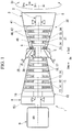
- FIG. 1 and FIG. 2 An embodiment of a gas turbine according to the present invention will be described with reference to FIG. 1 and FIG. 2 .
- a gas turbine 1 of this embodiment includes a compressor 10 that generates compressed air Acom by compressing outside air A, combustors 20 that generate combustion gas G by combusting fuel F from a fuel supply source in the compressed air Acom, and a turbine 30 that is driven by the combustion gas G.
- the compressor 10 has a compressor rotor 11 that rotates around an axis Ar, and a cylindrical compressor casing 15 that covers the compressor rotor 11.
- the direction in which the axis Ar extends will be referred to as an axial direction Da.
- One side in the axial direction Da will be referred to as an axially upstream side Dau, and the other side in the axial direction Da will be referred to as an axially downstream side Dad.
- the radial direction based on the axis Ar will be referred to simply as a radial direction Dr.
- the side in the radial direction Dr away from the axis Ar will be referred to as a radially outer side Dro, and the side in the radial direction Dr toward the axis Ar will be referred to as a radially inner side Dri.
- the compressor casing 15 has an opening formed on the upstream side. This opening constitutes an air intake opening 15i through which the outside air A is taken into the compressor 10 from the outside.
- a plurality of stator vane rows 16 is fixed on the radially inner side Dri of the compressor casing 15. The stator vane rows 16 are arrayed at intervals in the axial direction Da. Each stator vane row 16 is composed of a plurality of stator vanes 17 that is arrayed in a circumferential direction Dc based on the axis Ar.
- the compressor rotor 11 has a rotor shaft 12 that extends in the axial direction Da around the axis Ar, and a plurality of rotor vane rows 13 that is foxed on the outer circumference of the rotor shaft 12. Each rotor vane row 13 is disposed on the axially upstream side Dau of one stator vane row 16. Each rotor vane row 13 is composed of a plurality of rotor vanes 14 that is arrayed in the circumferential direction Dc.
- the turbine 30 is disposed on the axially downstream side Dad of the compressor 10.
- the turbine 30 has a turbine rotor 31 that rotates around the axis Ar, and a cylindrical turbine casing 41 that covers the turbine rotor 31.
- a plurality of stator vane rows 46 is fixed on the radially inner side Dri of the turbine casing 41.
- the stator vane rows 46 are arrayed at intervals in the axial direction Da.
- Each stator vane row 46 is composed of a plurality of stator vanes 47 that is arrayed in the circumferential direction Dc.
- the turbine rotor 31 has a rotor shaft 32 that extends in the axial direction Da around the axis Ar, and a plurality of rotor vane rows 33 that is fixed on the outer circumference of the rotor shaft 32.
- Each rotor vane row 33 is disposed on the axially downstream side Dad of one stator vane row 46.
- Each rotor vane row 33 is composed of a plurality of rotor vanes 34 that is arrayed in the circumferential direction Dc.
- the gas turbine 1 of this embodiment further includes an intermediate casing 5 and an exhaust chamber 6.
- the intermediate casing 5 is disposed between the compressor casing 15 and the turbine casing 41 in the axial direction Da.
- the exhaust chamber 6 is disposed on the axially downstream side Dad of the turbine casing 41.
- the compressor casing 15, the intermediate casing 5, the turbine casing 41, and the exhaust chamber 6 are coupled to one another to form a gas turbine casing 3.
- the compressor rotor 11 and the turbine rotor 31 rotate integrally around the same axis Ar.
- the compressor rotor 11 and the turbine rotor 31 form a gas turbine rotor 2.
- the gas turbine rotor 2 is supported by a bearing at each end thereof in the axial direction Da.
- a rotor of a generator 9 is connected to the gas turbine rotor 2.
- the combustors 20 are fixed to the intermediate casing 5.
- a fuel line 25 through which the fuel F is supplied to the combustor 20 is connected to the combustor 20.
- a fuel regulation valve 26 that regulates the flow rate of the fuel is provided in the fuel line 25.
- the turbine casing 41 has a plurality of ring segments 42, a plurality of isolation rings 43, a vane ring 44 as a first part, and a casing body 45.
- the ring segments 42 are located on the radially outer side Dro of the rotor vane row 33 and face the rotor vane row 33 in the radial direction Dr.
- the vane ring 44 has an annular shape around the axis Ar and is located on the radially outer side Dro of the ring segments 42.
- the isolation ring 43 is located between the ring segments 42 and the stator vanes 47 on one side and the isolation ring 43 on the other side in the radial direction Dr, and connects the ring segments 42 and the stator vanes 47 to the isolation ring 43.
- the casing body 45 has an annular shape around the axis Ar and is located on the radially outer side Dro of the vane ring 44.
- the casing body 45 supports the vane ring 44 from the radially outer side Dro.
- the intermediate casing 5 is connected on the axially upstream side Dau of the casing body 45.
- the exhaust chamber 6 is connected on the axially downstream side Dad of the casing body 45.
- An annular space between the radially outer side Dro of the rotor shaft 32 and the radially inner side Dri of the turbine casing 41 forms a combustion gas flow path 49 through which the combustion gas G from the combustors 20 flows.
- the rotor shaft 32 has a cooling air passage formed therein through which cooling air passes. Cooling air having passed through this cooling air passage is introduced into the rotor vanes 34 and used to cool the rotor vanes 34.
- the turbine casing 41 has a cooling air passage formed therein through which cooling air passes. Cooling air having passed through this cooling air passage is introduced into the stator vanes 47 and the ring segments 42 and used to cool the stator vanes 47 and the ring segments 42.
- air inside the intermediate casing 5 is supplied as cooling air to the stator vanes 47 composing these stator vane rows 46 without passing through the cooling air passage of the casing.
- stator vane An embodiment of a stator vane according to the present invention and various modified examples thereof will be described below with reference to FIG. 3 to FIG. 15 .
- Each stator vane to be described below is a specific example of the stator vane described above in "Embodiment of Gas Turbine.”
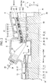
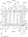
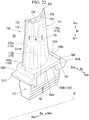
- a stator vane 50 of this embodiment has a vane body 51 extending in the radial direction Dr, an inner shroud 60i formed on the radially inner side Dri of the vane body 51, and an outer shroud 60o formed on the radially outer side Dro of the vane body 51.
- the vane body 51 is disposed inside the combustion gas flow path 49 (see FIG. 2 ) through which the combustion gas G passes.
- the inner shroud 60i defines the perimeter of the annular combustion gas flow path 49 on the radially inner side Dri.
- the outer shroud 60o defines the perimeter of the annular combustion gas flow path 49 on the radially outer side Dro.
- each of the inner shroud 60i and the outer shroud 60o is a flow path forming plate that defines a part of the combustion gas flow path 49.
- the vane body 51 forms an airfoil.
- the end of the vane body 51 on the axially upstream side Dau forms a leading edge 52, and the end thereof on the axially downstream side Dad forms a trailing edge 53.
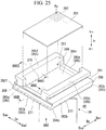
- the inner shroud 60i that is a flow path forming plate has an inner shroud body 61i and a peripheral wall 65i.
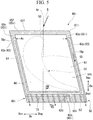
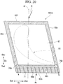
- the inner shroud body 61i has a front end surface 62f that is an end surface on the axially upstream side Dau, a back end surface 62b that is an end surface on the axially downstream side Dad, a pair of circumferential end surfaces 63 facing opposite sides in the circumferential direction Dc, a gas path surface 64p facing the radially outer side Dro, and an opposite-gas-path surface 64i facing the radially inner side Dri.
- the end surface on the circumferential pressure side Dcp forms a pressure-side end surface 63p
- the end surface on the circumferential suction side Den forms a suction-side end surface 63n
- the front end surface 62f and the back end surface 62b are roughly parallel to each other.
- the pressure-side end surface 63p and the suction-side end surface 63n are roughly parallel to each other.
- the inner shroud body 61i has a parallelogram shape when seen from the radial direction Dc.
- the peripheral wall 65i protrudes from the opposite-gas-path surface 64i of the inner shroud body 61i toward the radially inner side Dri (opposite-flow-path side).
- the peripheral wall 65i is provided along the end surfaces of the inner shroud body 61i.
- the peripheral wall 65i has a front wall 65f and a back wall 65b facing each other in the axial direction Da, and a pair of side walls 65p, 65n facing each other in the circumferential direction Dc.
- the side wall on the circumferential pressure side Dcp forms a pressure-side wall 65p
- the side wall on the circumferential suction side Den forms a suction-side wall 65n.
- Each of the front wall 65f and the back wall 65b protrudes relative to the inner shroud body 61i, farther toward the radially inner side Dri than the pair of side walls 65p, 65n.
- the inner shroud 60i has a recess 66 (see FIG. 4 and FIG. 5 ) that is formed by the inner shroud body 61i and the peripheral wall 65i and recessed toward the radially outer side Dro.
- the surface of the pressure-side wall 65p on the circumferential pressure side Dcp and the surface of the inner shroud body 61i on the circumferential pressure side Dcp are flush with each other.
- the surface of the suction-side wall 65n on the circumferential suction side Dcn and the surface of the inner shroud body 61i on the circumferential suction side Den are flush with each other.
- the back wall 65b is formed along the back end surface 62b of the inner shroud body 61i, but is formed farther on the axially upstream side Dau than the back end surface 62b.
- the surface on the axially upstream side Dau with the back wall 65b as a reference point forms the bottom surface of the recess 66.
- the surface on the axially downstream side Dad with the back wall 65b as a reference point does not form the bottom surface of the recess 66 but forms an outer opposite-gas-path surface 64io.
- the outer opposite-gas-path surface 64io of the inner shroud 60i is formed so as to extend gradually closer to the gas path surface 64p while extending toward the axially downstream side Dad.
- the opposite-flow-path side refers to the side in the radial direction Dr away from the combustion gas flow path 49 or the gas path surface 64p
- the flow path side refers to the side in the radial direction Dr toward the combustion gas flow path 49 or the gas path surface 64p.
- the flow path side coincides with the radially outer side Dro and the opposite-flow-path side coincides with the radially inner side Dri.
- the flow path side coincides with the radially inner side Dri and the opposite-flow-path side coincides with the radially outer side Dro.
- the stator vanes 50 composing one of the stator vane rows 46 are each provided with a retainer 85 that protrudes from the pair of side walls 65p, 65n of the inner shroud 60i toward the radially inner side Dri.
- the retainer 85 is located between the front wall 65f and the back wall 65b in the axial direction Da, and is formed across the pressure-side end surface 63p and the suction-side end surface 63n.
- the pressure-side end surface of the retainer 85 is flush with the pressure-side end surface 63p of the inner shroud body 61i. Although this is not shown, the suction-side end surface of the retainer 85 is flush with the suction-side end surface 63n of the inner shroud body 61i.
- the retainer 85 comes in contact with a radially outer end 8a (see FIG. 4 ) on the downstream side of an inner cover 8 that is fixed to the gas turbine casing 3, and thus serves to support a part of the stator vane 50 on the radially inner side Dri onto the radially outer end 8a of the inner cover 8.
- the retainer 85 has an opening 86 (hereinafter referred to as a retainer opening 86) that is formed therethrough in the axial direction Da.
- a space formed by the retainer opening 86 communicates with a space formed by the recess 66 of the inner shroud 60i.
- the stator vane 50 further includes an impingement plate 81.
- the stator vane 50 provided with the retainer 85 further includes an impingement plate 81 and a seal plate 83.
- the impingement plate 81 partitions the space inside the recess 66 of the inner shroud 60i into an outer cavity 66a that is a region on the radially inner side Dri and an inner cavity 67 that is a region on the radially outer side Dro.
- the impingement plate 81 has a plurality of through-holes 82 that is formed therethrough in the radial direction Dr.
- the cooling air Ac impinges on the bottom surface of the recess 66 and performs impingement cooling on this bottom surface.
- the seal plate 83 closes a part of the opening of the recess 66 farther on the axially downstream side Dad than the retainer 85.
- the seal plate 83 is located farther on the downstream side Dad than the retainer 85 and farther on the radially inner side Dri than the impingement plate 81.
- the outer shroud 60o that is a flow path forming plate has an outer shroud body 61o and a peripheral wall 65o.
- the outer shroud body 61o has a front end surface 62f, a back end surface 62b, a pair of circumferential end surfaces 63, a gas path surface 64p, and an opposite-gas-path surface 64i.
- the end surface on the circumferential pressure side Dcp forms a pressure-side end surface 63p
- the end surface on the circumferential suction side Dcn forms a suction-side end surface 63n.
- the outer shroud body 61o has a parallelogram shape when seen from the radial direction Dc.
- the gas path surface 64p of the inner shroud body 61i faces the radially outer side Dro, while the gas path surface 64p of the outer shroud body 61o faces the radially inner side Dri.
- the peripheral wall 65o has a front wall 65f and a back wall 65b facing each other in the axial direction Da, and a pair of side walls 65p, 65n facing each other in the circumferential direction Dc.
- the side wall on the circumferential pressure side Dcp forms a pressure-side wall 65p
- the side wall on the circumferential suction side Dcn forms a suction-side wall 65n.
- Each of the front wall 65f and the back wall 65b protrudes relative to the outer shroud body 61o, farther toward the radially outer side Dro than the pair of side walls 65p, 65n and forms a hook.
- the front wall 65f and the back wall 65b forming the hooks serve to mount the stator vane 50 onto the inner circumferential side of the turbine casing 41. Specifically, the front wall 65f and the back wall 65b forming the hooks are mounted on the isolation ring 43 (see FIG. 2 ) that forms a part of the turbine casing 41.
- the outer shroud 60o has a recess 66 that is formed by the outer shroud body 61o and the peripheral wall 65o and recessed toward the radially inner side Dri.
- the surface of the pressure-side wall 65p on the circumferential pressure side Dcp and the surface of the outer shroud body 61o on the circumferential pressure side Dcp are flush with each other.
- the surface of the suction-side wall 65n on the circumferential suction side Den and the surface of the outer shroud body 61o on the circumferential suction side Den are flush with each other.
- the back wall 65b is formed along the back end surface 62b of the outer shroud body 61o, but is formed farther on the axially upstream side Dau than the back end surface 62b.
- the surface on the axially upstream side Dau with the back wall 65b as a reference point forms the bottom surface of the recess 66.
- the surface on the axially downstream side Dad with the back wall 65b as a reference point does not form the bottom surface of the recess 66 but forms an outer opposite-gas-path surface 64io.
- the outer opposite-gas-path surface 64io of the outer shroud 60o is formed so as to extend gradually closer to the gas path surface 64p while extending toward the axially downstream side Dad.
- the stator vane 50 further includes an impingement plate 81 that partitions a space inside the recess 66 of the outer shroud 60o into a region on the radially outer side Dro and an inner cavity 67 that is a region on the radially inner side Dri.
- the impingement plate 81 has a plurality of through-holes 82 that is formed therethrough in the radial direction Dr. Part of the cooling air Ac present on the radially outer side Dro of the stator vane 50 flows into the inner cavity 67 through the through-holes 82 of the impingement plate 81.
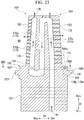
- a plurality of vane air passages 75 extending in the radial direction Dr is formed inside the vane body 51, the outer shroud 60o, and the inner shroud 60i.
- Each vane air passage 75 extends continuously from the outer shroud 60o through the vane body 51 to the inner shroud 60i.
- the vane air passages 75 are arrayed along the mean line of the vane body 51. Some of the vane air passages 75 that are adjacent to each other communicate with each other at a part on the radially outer side Dro or at a part on the radially inner side Dri. Moreover, one of the vane air passages 75 is open on the radially outer side Dro.
- the vane air passage 75 located farthest on the axially upstream side Dau is a first vane air passage 75a.
- a second vane air passage 75b, a third vane air passage 75c, and a fourth vane air passage 75d are arrayed in this order on the axially downstream side Dad with the first vane air passage 75a as a reference point.
- the second vane air passage 75b communicates at a part on the radially inner side Dri with a part of the third vane air passage 75c on the radially inner side Dri.
- the third vane air passage 75c communicates at a part on the radially outer side Dro with a part of the fourth vane air passage 75d on the radially outer side Dro.
- first vane air passage 75a and the second vane air passage 75b on the radially outer side Dro protrude from the impingement plate 81 of the outer shroud 60o toward the radially outer side Dro.
- the ends of the first vane air passage 75a and the second vane air passage 75b on the radially outer side Dro open in the opposite-gas-path surface 64i of the outer shroud 60o.
- the first vane air passage 75a and the second vane air passage 75b communicate with the space inside the recess 66 of the outer shroud 60o.
- the cooling air Ac flows into the first vane air passage 75a and the second vane air passage 75b through these openings.
- the ends of the third vane air passage 75c and the fourth vane air passage 75d on the radially outer side Dro are closed.
- the ends of the first vane air passage 75a, the second vane air passage 75b, the third vane air passage 75c, and the fourth vane air passage 75d on the radially outer side Dro are closed.
- Each of the leading edge 52 and the trailing edge 53 of the vane body 51 has a plurality of vane surface blow-out passages 76 that is formed therethrough from the vane air passage 75 to the combustion gas flow path 49.
- the vane body 51 is cooled in the process of the cooling air Ac flowing through the vane air passages 75.
- the cooling air Ac having flowed into the vane air passages 75 flows out from the vane surface blow-out passages 76 into the combustion gas flow path 49.
- the leading edge 52 and the trailing edge 53 of the vane body 51 are cooled in the process of the cooling air Ac flowing out from the vane surface blow-out passages 76.
- part of the cooling air Ac having flowed out from the vane surface blow-out passages 76 to the combustion gas flow path 49 serves as film cooling air by partially covering the surface of the vane body 51.
- the pressure-side wall 65p of the inner shroud 60i has a pressure-side passage 78p that extends along the pressure-side end surface 63p in a direction having a component of the axial direction Da.
- the suction-side wall 65n has a suction-side passage 78n that extends along the suction-side end surface 63n in a direction having a component of the axial direction Da.
- Each of the pressure-side passage 78p and the suction-side passage 78n communicates at the end thereof on the axially upstream side Dau with the inner cavity 67.
- the inner shroud body 61i has a back-side passage 90i that extends along the back end surface 62b in the circumferential direction Dc.
- the end of the back-side passage (first side passage) 90i on the circumferential pressure side Dcp communicates with the end of the pressure-side passage (second side passage) 78p on the axially downstream side Dad.
- the end of the back-side passage (first side passage) 90i on the circumferential suction side Dcn communicates with the end of the suction-side passage (third side passage) 78n on the axially downstream side Dad.
- the position of the back-side passage 90i in the axial direction Da overlaps a region which is located farther on the axially downstream side Dad than the trailing edge 53 of the vane body 51 and in which the back wall 65b is formed (see FIG. 4 ).
- a plurality of back end surface blow-out passages 71 communicates with the back-side passage 90i.
- Each back end surface blow-out passage 71 extends from the back-side passage 90i toward the axially downstream side Dad and opens in the back end surface 62b of the inner shroud body 61i.
- air having passed through the back end surface blow-out passages 71 flows out into the combustion gas flow path 49 through these openings.
- the back end surface blow-out passages 71 are arrayed in the circumferential direction Dc.
- the pressure-side wall 65p of the outer shroud 60o has a pressure-side passage 78p that extends along the pressure-side end surface 63p in a direction having a component of the axial direction Da.
- the suction-side wall 65n of the outer shroud 60o has a suction-side passage 78n that extends along the suction-side end surface 63n in a direction having a component of the axial direction Da.
- Each of the pressure-side passage 78p and the suction-side passage 78n communicates at the end thereof on the axially upstream side Dau with the inner cavity 67.
- the outer shroud body 61o has a back-side passage 90o that extends along the back end surface 62b in the circumferential direction Dc.
- the end of the back-side passage (first side passage) 90o on the circumferential pressure side Dcp communicates with the end of the pressure-side passage (second side passage) 78p on the axially downstream side Dad.
- the end of the back-side passage (first side passage) 90o on the circumferential suction side Dcn communicates with the end of the suction-side passage (third side passage) 78n on the axially downstream side Dad.
- air having passed through the back end surface blow-out passages 71 flows out into the combustion gas flow path 49 through these openings.
- the back end surface blow-out passages 71 are arrayed in the circumferential direction Dc.
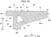
- the cross-section of the back-side passage 90i in the inner shroud 60i has an irregular quadrangular shape.
- the back-side passage 90i is defined by a plurality of passage forming surfaces including a first forming surface 91, a second forming surface 92, a third forming surface 93, and a fourth forming surface 94.
- the edge included in the first forming surface 91, the edge included in the second forming surface 92, the edge included in the third forming surface 93, and the edge included in the fourth forming surface 94 are all substantially straight lines.
- the first forming surface 91, the second forming surface 92, the third forming surface 93, and the fourth forming surface 94 are all curved surfaces that extend in the circumferential direction Dc and curve gradually as they extend in the circumferential direction Dc.
- the first forming surface 91 faces the radially inner side Dri (opposite-flow-path side) and extends gradually farther away from the gas path surface 64p while extending toward the axially downstream side Dad (end surface side).
- the first forming surface 91 faces the opposite-flow-path side and extends gradually farther away from the gas path surface 64p while extending toward the end surface side that is the side toward the back end surface 62b being the first end surface.
- the second forming surface 92 faces the radially inner side Dri (opposite-flow-path side) and extends from the end of the first forming surface 91 on the axially upstream side Dau (opposite-end-surface side) toward the axially upstream side Dau (opposite-end-surface side).
- the second forming surface 92 faces the radially inner side Dri (opposite-flow-path side) and extends from the end of the first forming surface 91 closest to the gas path surface 64p toward the opposite-end-surface side that is the side away from the back end surface 62b being the first end surface.
- the second forming surface 92 is substantially parallel to the gas path surface 64p.
- the fourth forming surface 94 extends from the end of the second forming surface 92 on the axially upstream side Dau toward the radially inner side Dri.
- the fourth forming surface 94 is substantially parallel to the surface of the back wall 65b that is the inner surface thereof facing the recess 66.
- the third forming surface 93 faces the radially outer side Dro and extends gradually closer to the gas path surface 64p while extending toward the axially downstream side Dad.
- the end of the third forming surface 93 on the axially upstream side Dau joins the end of the fourth forming surface 94 on the radially inner side Dri.
- the end of the third forming surface 93 on the axially downstream side Dad joins the end of the first forming surface 91 on the axially downstream side Dad.
- the third forming surface 93 is substantially parallel to the outer opposite-gas-path surface 64io.
- Each back end surface blow-out passage 71 opens in the first forming surface 91.
- the cooling air Ac flows into the back-side passage 90i from the pressure-side passage 78p and the suction-side passage 78n.
- the cooling air Ac performs convective cooling on a part of the inner shroud body 61i on the axially downstream side Dad.
- the cooling air Ac having flowed into the back-side passage 90i flows into the back end surface blow-out passages 71.
- the cooling air Ac performs convective cooling on the part of the inner shroud body 61i on the axially downstream side Dad.
- the cooling air Ac flows out from the openings in the back end surface 62b.
- the passage cross-sectional area of the back-side passage 90i is larger than the passage cross-sectional area of the back end surface blow-out passage 71. This is to restrict the flow velocity of the cooling air Ac flowing through the back-side passage 90i, and thereby to reduce the pressure loss of the cooling air Ac in the process of flowing through the back-side passage 90i. Accordingly, the cooling air Ac flowing through the back end surface blow-out passage 71 has a higher effect of convective cooling per unit passage cross-sectional area than the cooling air Ac flowing through the back-side passage 90i.
- the passage cross-sectional area here refers to the passage area in the cross-section perpendicular to the longitudinal direction of the passage.
- the back end surface blow-out passages 71 having a high cooling effect have a long passage length.
- each back end surface blow-out passage 71 on the axially upstream side Dau overlaps a back-side passage 90ii as seen from the radial direction Dr.
- These back end surface blow-out passages 71 open in a forming surface m, at positions farther on the axially upstream side Dau than a part located farthest on the axially downstream side Dad in the passage cross-section of the back-side passage 90ii.
- the forming surface m faces the gas path surface 64p, i.e., the flow path side.
- the gas path surface 64p is effectively cooled along the entire passage length of the back end surface blow-out passages 71.
- the gas path surface 64p is effectively cooled as described above along the entire passage length of the back end surface blow out passages 71 having high cooling efficiency.
- the back end surface blow-out passages 71 having high cooling efficiency sufficiently contribute to cooling the gas path surface 64p along the entire passage length thereof.
- the back end surface blow-out passages 71 To secure a long passage length of the back end surface blow-out passages 71 and contribute to cooling the gas path surface 64p along the entire passage length of the back end surface blow-out passages 71, it is necessary to form, as one of the passage forming surfaces forming the back-side passage 90i, the first forming surface 91 that faces the radially inner side Dri and extends gradually farther away from the gas path surface 64p while extending toward the axially downstream side Dad as described above. Moreover, it is necessary to form the openings of the back end surface blow-out passages 71 in the first forming surface 91.
- the cross-section of the back-side passage 90i has an irregular quadrangular shape.
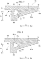
- various cross-sectional shapes of the back-side passage will be described using FIG. 8 to FIG. 13 .
- the cross-section of a back-side passage 90ia in this modified example has a substantially isosceles trapezoidal shape.
- the back-side passage 90ia is defined by a plurality of passage forming surfaces including a first forming surface 91a, a third forming surface 93a, a fourth forming surface 94a, and a fifth forming surface 95a.
- the edge included in the first forming surface 91a, the edge included in the third forming surface 93a, the edge included in the fourth forming surface 94a, and the edge included in the fifth forming surface 95a are all substantially straight lines.
- the first forming surface 91a, the third forming surface 93a, the fourth forming surface 94a, and the fifth forming surface 95a are all curved surfaces that extend in the circumferential direction Dc and curve gradually as they extend in the circumferential direction Dc.
- the first forming surface 91a of this modified example faces the radially inner side Dri and extends gradually farther away from the gas path surface 64p while extending toward the axially downstream side Dad.
- the fourth forming surface 94a faces the axially downstream side Dad and spreads from the end of the first forming surface 91a on the axially upstream side Dau toward the radially inner side Dri.
- the fourth forming surface 94a is substantially parallel to the surface of the back wall 65b that is the inner surface thereof facing the recess 66.
- the third forming surface 93a faces the radially outer side Dro and extends gradually closer to the gas path surface 64p while extending toward the axially downstream side Dad.
- the third forming surface 93a is substantially parallel to the outer opposite-gas-path surface 64io.
- the end of the third forming surface 93a on the axially upstream side Dau joins the end of the fourth forming surface 94a on the radially inner side Dri.
- the fifth forming surface 95a faces the axially upstream side Dau and spreads from the end of the third forming surface 93a on the axially downstream side Dad toward the radially outer side Dro.
- the fifth forming surface 95a is substantially parallel to the fourth forming surface 94a.
- the end of the fifth forming surface 95a on the radially outer side Dro joins the end of the first forming surface 91a on the axially downstream side Dad.
- the first forming surface 91a and the fourth forming surface 94a directly join each other, which is different from the above embodiment in which there is the second forming surface 92 between the first forming surface 91 and the fourth forming surface 94.
- the back end surface blow-out passages 71 open in the first forming surface 91a that faces the radially inner side Dri (opposite-flow-path side) and extends gradually farther away from the gas path surface 64p while extending toward the axially downstream side Dad.
- Dri opposite-flow-path side
- the cross-section of a back-side passage 90ib of this modified example has a substantially trapezoidal shape.
- the back-side passage 90ib is defined by a plurality of passage forming surfaces including a first forming surface 91b, a fourth forming surface 94b, a fifth forming surface 95b, and a sixth forming surface 96b.
- the edge included in the first forming surface 91b, the edge included in the fourth forming surface 94b, the edge included in the fifth forming surface 95b, and the edge included in the sixth forming surface 96b are all substantially straight lines.
- the first forming surface 91b, the fourth forming surface 94b, the fifth forming surface 95b, and the sixth forming surface 96b are all curved surfaces that extend in the circumferential direction Dc and curve gradually as they extend in the circumferential direction Dc.
- the first forming surface 91b of this modified example faces the radially inner side Dri and extends gradually farther away from the gas path surface 64p while extending toward the axially downstream side Dad.
- the fourth forming surface 94b faces the axially downstream side Dad and spreads from the end of the first forming surface 91b on the axially upstream side Dau toward the radially inner side Dri.
- the fourth forming surface 94b is substantially parallel to the surface of the back wall 65b that is the inner surface thereof facing the recess 66.
- the sixth forming surface 96b faces the radially outer side Dro and is substantially parallel to the gas path surface 64p.
- the end of the sixth forming surface 96b on the axially upstream side Dau joins the end of the fourth forming surface 94b on the radially inner side Dri.
- the fifth forming surface 95b faces the axially upstream side Dau and spreads from the end of the sixth forming surface 96b on the axially downstream side Dad toward the radially outer side Dro.
- the fifth forming surface 95b is substantially parallel to the fourth forming surface 94b.
- the end of the fifth forming surface 95b on the radially outer side Dro joins the end of the first forming surface 91b on the axially downstream side Dad.
- the back end surface blow-out passages 71 open in the first forming surface 91b that faces the radially inner side Dri (opposite-flow-path side) and extends gradually farther away from the gas path surface 64p while extending toward the axially downstream side Dad.
- Dri opposite-flow-path side
- an allowable distance D is determined in view of the strength of the flow path forming plate, the ease of production in the process of manufacturing the flow path forming plate, etc. Accordingly, the passage forming surfaces of the back-side passage 90ib are required to be at the allowable distance D or farther away from the surfaces present on the outer side of the back-side passage 90ib. On the other hand, the back-side passage 90ib is required to have a large passage cross-sectional area in order to reduce the pressure loss of the cooling air Ac in the process of flowing through the back-side passage 90ib.
- the fourth forming surfaces 94, 94a are formed so as to be substantially parallel to the surface of the back wall 65b that is the inner surface thereof facing the recess 66, and the third forming surfaces 93, 93a are formed so as to be substantially parallel to the outer opposite-gas-path surface 64io.
- the fourth forming surface 94b is substantially parallel to the surface of the back wall 65b that is the inner surface thereof facing the recess 66.
- the sixth forming surface 96b that is closest to the outer opposite-gas-path surface 64io is not parallel to the outer opposite-gas-path surface 64io. Accordingly, when the distance from the outer opposite-gas-path surface 64io to the position of the end of the sixth forming surface 96b on the axially downstream side Dad is set to the allowable distance D, the rest of the sixth forming surface 96b is distanced from the outer opposite-gas-path surface 64io more than necessary, reducing the passage cross-sectional area of the back-side passage 90ib.
- the above embodiment and the first modified example are more advantageous than this modified example in terms of securing a large passage cross-sectional area of the back-side passage.
- a third modified example of the back-side passage will be described with reference to FIG. 10 .
- the cross-section of a back-side passage 90ic of this modified example has a substantially regular triangular shape.
- the back-side passage 90ic is defined by a plurality of passage forming surfaces including a first forming surface 91c, a third forming surface 93c, and a fourth forming surface 94c.
- the edge included in the first forming surface 91c, the edge included in the third forming surface 93c, and the edge included in the fourth forming surface 94c are all substantially straight lines.
- the first forming surface 91c, the third forming surface 93c, and the fourth forming surface 94c are all curved surfaces that extend in the circumferential direction Dc and curve gradually as they extend in the circumferential direction Dc.
- the first forming surface 91c of this modified example faces the radially inner side Dri and extends gradually farther away from the gas path surface 64p while extending toward the axially downstream side Dad.
- the fourth forming surface 94c faces the axially downstream side Dad and spreads from the end of the first forming surface 91c on the axially upstream side Dau toward the radially inner side Dri.
- the fourth forming surface 94c is substantially parallel to the surface of the back wall 65b that is the inner surface thereof facing the recess 66.
- the third forming surface 93c faces the radially outer side Dro and extends gradually closer to the gas path surface 64p while extending toward the axially downstream side Dad.
- the third forming surface 93c is substantially parallel to the outer opposite-gas-path surface 64io.
- the end of the third forming surface 93c on the axially upstream side Dau joins the end of the fourth forming surface 94c on the radially inner side Dri.
- the end of the third forming surface 93c on the axially downstream side Dad joins the end of the first forming surface 91c on the axially downstream side Dad.
- the first forming surface 91c and the fourth forming surface 94c directly join each other, which is different from the above embodiment in which there is the second forming surface 92 between the first forming surface 91 and the fourth forming surface 94.
- the back end surface blow-out passages 71 open in the first forming surface 91c that faces the radially inner side Dri (opposite-flow-path side) and extends gradually farther away from the gas path surface 64p while extending toward the axially downstream side Dad.
- the cross-section of the back-side passage need not have a quadrangular shape as in the above examples, and the same effects as those of the above embodiment can be achieved even when the back-side passage has a triangular cross-sectional shape.
- the corner formed by the first forming surface 91c and the fourth forming surface 94c, the corner formed by the fourth forming surface 94c and the third forming surface 93c, and the corner formed by the third forming surface 93c and the first forming surface 91c each have an acute angle.
- the corners formed by the adjacent forming surfaces thus each have an acute angle, an uneven flow of the cooling air Ac occurs near the corners, which results in a flow velocity distribution of the cooling air Ac within the passage cross-section of the back-side passage 90ic.
- the flow velocity of the cooling air Ac is higher near the opening of the back end surface blow-out passage 71 in the passage cross-section of the back-side passage 90ic, and thus a flow velocity distribution of the cooling air Ac occurs along the first forming surface 91 within the passage cross-section of the back-side passage 90ic. For this reason, the flow rate of the cooling air Ac flowing from the back-side passage 90ic into the back end surface blow-out passages 71 is restricted compared with that in the above embodiment. It is therefore preferable that the number of corners having an acute angle be as small as possible when there is a plurality of corners formed by the adjacent forming surfaces.
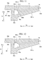
- a fourth modified example of the back-side passage will be described with reference to FIG. 11 .
- the cross-section of a back-side passage 90id of this modified example has an irregular hexagonal shape.
- the back-side passage 90id is defined by a plurality of passage forming surfaces including a first forming surface 91d, a second forming surface 92d, a third forming surface 93d, a fourth forming surface 94d, a fifth forming surface 95d, and a sixth forming surface 96d.
- the edge included in the first forming surface 91c, the edge included in the second forming surface 92d, the edge included in the third forming surface 93d, the edge included in the fourth forming surface 94c, the edge included in the fifth forming surface 95d, and the edge included in the sixth forming surface 96d are all substantially straight lines.
- the first forming surface 91d, the second forming surface 92d, the third forming surface 93d, the fourth forming surface 94d, the fifth forming surface 95d, and the sixth forming surface 96d are all curved surfaces that extend in the circumferential direction Dc and curve gradually as they extend in the circumferential direction Dc.
- the first forming surface 91d of this modified example faces the radially inner side Dri and extends gradually farther away from the gas path surface 64p while extending toward the axially downstream side Dad.
- the second forming surface 92d faces the radially inner side Dri and spreads from the end of the first forming surface 91d on the axially upstream side Dau toward the axially upstream side Dau.
- the second forming surface 92d is substantially parallel to the gas path surface 64p.
- the fourth forming surface 94d faces the axially downstream side Dad and spreads from the end of the second forming surface 92d on the axially upstream side Dau toward the radially inner side Dri.
- the fourth forming surface 94d is substantially parallel to the surface of the back wall 65b that is the inner surface thereof facing the recess 66.
- the sixth forming surface 96d faces the radially outer side Dro and is substantially parallel to the gas path surface 64p and the second forming surface 92d.
- the end of the sixth forming surface 96d on the axially upstream side Dau joins the end of the fourth forming surface 94d on the radially inner side Dri.
- the third forming surface 93d faces the radially outer side Dro and extends gradually closer to the gas path surface 64p while extending toward the axially downstream side Dad.
- the end of the third forming surface 93d on the axially upstream side Dau joins the end of the sixth forming surface 96d on the axially downstream side Dad.
- the fifth forming surface 95d faces the axially upstream side Dau and spreads from the end of the third forming surface 93d on the axially downstream side Dad toward the radially outer side Dro.
- the fifth forming surface 95d is substantially parallel to the fourth forming surface 94d.
- the end of the fifth forming surface 95d on the radially outer side Dro joins the end of the first forming surface 91d on the axially downstream side Dad.
- the back end surface blow-out passages 71 open in the first forming surface 91d that faces the radially inner side Dri (opposite-flow-path side) and extends gradually farther away from the gas path surface 64p while extending toward the axially downstream side Dad.
- the cross-section of the back-side passage need not have a quadrangular shape as in the above examples, and the same effects as those of the above embodiment can be achieved even when the back-side passage has a polygonal shape with a larger number of edges than a quadrangle.
- the fourth forming surface 94d is substantially parallel to the surface of the back wall 65b that is the inner surface thereof facing the recess 66, and the third forming surface 93d is substantially parallel to the outer opposite-gas-path surface 64io.
- the corners formed by the adjacent forming surfaces each have an obtuse angle.
- the problem of an uneven flow of the cooling air Ac attributable to the corners formed by the adjacent forming surfaces having acute angles does not arise.
- a fifth modified example of the back-side passage will be described with reference to FIG. 12 .
- a back-side passage 90ie in this modified example is defined by a plurality of passage forming surfaces including a first forming surface 91e, a second forming surface 92e, a third forming surface 93e, and a fourth forming surface 94e.
- the edge included in the second forming surface 92e, the edge included in the third forming surface 93e, and the edge included in the fourth forming surface 94e are all substantially straight lines.
- the second forming surface 92e, the third forming surface 93e, and the fourth forming surface 94e are all curved surfaces that extend in the circumferential direction Dc and curve gradually as they extend in the circumferential direction Dc.
- the first forming surface 91e of this modified example faces the radially inner side Dri and extends gradually farther away from the gas path surface 64p while extending toward the axially downstream side Dad.
- the edge included in the first forming surface 91e is a smoothly curved line that protrudes from the inner side of the back-side passage 90ie toward the outer side.
- the first forming surface 91e is a curved surface that extends in the circumferential direction Dc and curves gradually as it extends in the circumferential direction Dc. Also in this modified example, the second forming surface 92e is substantially parallel to the gas path surface 64p.
- the back end surface blow-out passages 71 open in the first forming surface 91e that faces the radially inner side Dri (opposite-flow-path side) and extends gradually farther away from the gas path surface 64p while extending toward the axially downstream side Dad.
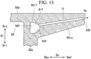
- a sixth modified example of the back-side passage will be described with reference to FIG. 13 .
- a back-side passage 90if of this modified example is defined by a plurality of passage forming surfaces including a first forming surface 91f, a fourth forming surface 94f, and a third forming surface 93f.
- the first forming surface 91f of this modified example faces the radially inner side Dri and extends gradually farther away from the gas path surface 64p while extending toward the axially downstream side Dad.
- the first forming surface 91f is a smoothly curved surface that protrudes from the inner side of the back-side passage 90if toward the outer side.
- the fourth forming surface 94f faces the axially downstream side Dad and spreads from the end of the first forming surface 91f on the axially downstream side Dad toward the radially inner side Dri.
- the fourth forming surface 94f is a flat surface that is substantially parallel to the surface of the back wall 65b that is the inner surface thereof facing the recess 66.
- the third forming surface 93f faces the radially outer side Dro and extends gradually closer to the gas path surface 64p while extending toward the axially downstream side Dad.
- the third forming surface 93f is a smoothly curved surface that protrudes from the inner side of the back-side passage 90if toward the outer side.
- the first forming surface 91 f and the third forming surface 93f are smoothly continuous with each other.
- the first forming surface 91f and the third forming surface 93f constitute one forming surface. Accordingly, in this modified example, of the edges forming the passage cross-section of the back-side passage 90if, both the edges included in the forming surfaces 94f, 93f other than the fourth forming surface 94f are curved lines.
- the back end surface blow-out passages 71 open in the first forming surface 91f that faces the radially inner side Dri (opposite-flow-path side) and extends gradually farther away from the gas path surface 64p while extending toward the axially downstream side Dad.
- Dri opposite-flow-path side
- the cross-section of a back-side passage 90ig of the first comparative example has a substantially square shape or a rectangular shape.
- the back-side passage 90ig is defined by four passage forming surfaces that are a forming surface a, a forming surface b, a forming surface c, and a forming surface d.
- the edge included in the forming surface a, the edge included in the forming surface b, the edge included in the forming surface c, and the edge included in the forming surface d are all substantially straight lines.
- the forming surface a, the forming surface b, the forming surface c, and the forming surface d are all curved surfaces that extend in the circumferential direction Dc and curve gradually as they extend in the circumferential direction Dc.
- the forming surface a faces the radially inner side Dri and is substantially parallel to the gas path surface 64p.
- the forming surface b spreads from the end of the forming surface a on the axially upstream side Dau toward the radially inner side Dri.
- the forming surface b is substantially perpendicular to the forming surface a and substantially parallel to the surface of the back wall 65b that is the inner surface thereof facing the recess 66.
- the forming surface c faces the radially outer side Dro and spreads from the end of the forming surface b on the radially inner side Dri toward the axially downstream side Dad.
- the forming surface c is substantially perpendicular to the forming surface b and substantially parallel to the gas path surface 64p and the forming surface a.
- the forming surface d spreads from the end of the forming surface c on the axially downstream side Dad toward the radially outer side Dro.
- the end of the forming surface d on the radially outer side Dro joins the end of the forming surface a on the axially downstream side Dad.
- the forming surface d is substantially perpendicular to the forming surface a and the forming surface c and substantially parallel to the forming surface b.
- the passage forming surfaces defining the back-side passage 90ig of the first comparative example do not include a forming surface that faces the radially inner side Dri and extends gradually farther away from the gas path surface 64p while extending toward the axially downstream side Dad.
- the back end surface blow-out passages 71 open in the forming surface d. Accordingly, in the first comparative example, the ends of the back end surface blow-out passages 71 on the axially upstream side Dau open at a part located farthest on the axially downstream side Dad in the passage forming surface forming the back-side passage 90ig.
- the passage length of the back end surface blow-out passages 71 having a high cooling effect is shorter than that in the above embodiment and modified examples.
- the cross-section of a back-side passage 90ih of the second comparative example has a shape of two rectangles intersecting each other.
- the back-side passage 90ih is defined by six passage forming surfaces that are a forming surface e, a forming surface f, a forming surface g, a forming surface h, a forming surface i, and a forming surface j.
- the edge included in the forming surface e, the edge included in the forming surface f, the edge included in the forming surface g, the edge included in the forming surface h, the edge included in the forming surface i, and the edge included in the forming surface j are all substantially straight lines.
- the forming surface e, the forming surface f, the forming surface g, the forming surface h, the forming surface i, and the forming surface j are all curved surfaces that extend in the circumferential direction Dc and curve gradually as they extend in the circumferential direction Dc.
- the forming surface e faces the radially inner side Dri and is substantially parallel to the gas path surface 64p.
- the forming surface f spreads from the end of the forming surface e on the axially upstream side Dau toward the radially inner side Dri.
- the forming surface f is substantially perpendicular to the forming surface e and substantially parallel to the surface of the back wall 65b that is the inner surface thereof facing the recess 66.
- the forming surface g faces the radially outer side Dro and extends gradually closer to the gas path surface 64p while extending toward the axially downstream side Dad.
- the end of the forming surface g on the axially upstream side Dau joins the end of the forming surface f on the radially inner side Dri.
- the forming surface h spreads from the end of the forming surface g on the axially downstream side Dad toward the radially outer side Dro.
- the forming surface h is substantially perpendicular to the forming surface g.
- the forming surface i faces the radially inner side Dri and extends gradually closer to the gas path surface 64p while extending toward the axially downstream side Dad.
- the forming surface i is substantially parallel to the forming surface g.
- the end of the forming surface i on the axially downstream side Dad joins the end of the forming surface h on the radially outer side Dro.
- the forming surface j spreads from the end of the forming surface i on the axially upstream side Dau toward the radially outer side Dro and is substantially parallel to the forming surface f.
- the end of the forming surface j on the radially outer side Dro joins the end of the forming surface e on the axially downstream side Dad.
- the back end surface blow-out passages 71 open in the forming surface j that is located farther on the axially upstream side Dau than a part located farthest on the axially downstream side Dad in the back-side passage 90ih.
- a long passage length of the back end surface blow-out passages 71 having a high cooling effect can be secured as in the above embodiment and modified examples.
- the second comparative example there is no forming surface that faces the radially inner side Dri and extends gradually farther away from the gas path surface 64p while extending toward the axially downstream side Dad.
- all the internal angles of the corners formed by the adjacent forming surfaces are not equal to or smaller than 180°, but the internal angle of the corner formed between the forming surface i and the forming surface j is larger than 180°.
- the internal angle refers to the angle of the angles formed by the adjacent forming surfaces that is on the inner side of the passage.
- the vertex of this corner protrudes to the inner side of the passage.
- the passage cross-sectional area of the back-side passage 90ih is reduced, so that the pressure loss of the cooling air Ac in the process of flowing through the back-side passage 90ih increases.
- the cross-section of the back-side passage 90ii of the third comparative example has a triangular shape.
- the back-side passage 90ii is defined by three passage forming surfaces that are a forming surface k, a forming surface 1, and the forming surface m.
- the edge included in the forming surface k, the edge included in the forming surface 1, and the edge included in the forming surface m are all substantially straight lines.
- the forming surface k, the forming surface 1, and the forming surface m are all curved surfaces that extend in the circumferential direction Dc and curve gradually as they extend in the circumferential direction Dc.
- the forming surface k faces the radially inner side Dri and is substantially parallel to the gas path surface 64p.
- the forming surface 1 spreads from the end of the forming surface k on the axially upstream side Dau toward the radially inner side Dri.
- the forming surface 1 is substantially perpendicular to the forming surface k and substantially parallel to the surface of the back wall 65b that is the inner surface thereof facing the recess 66.
- the forming surface m faces the radially outer side Dro and extends gradually closer to the gas path surface 64p while extending toward the axially downstream side Dad.
- the end of the forming surface m on the axially upstream side Dau joins the end of the forming surface 1 on the radially inner side Dri.
- the end of the forming surface m on the axially downstream side Dad joins the end of the forming surface k on the axially downstream side Dad.
- the back end surface blow-out passages 71 open in the forming surface m that faces the radially outer side Dro and extends gradually closer to the gas path surface 64p while extending toward the axially downstream side Dad.
- the back end surface blow-out passages 71 open at a part of the back-side passage 90ii located farther on the axially upstream side Dau than a part thereof located farthest on the axially downstream side Dad. Accordingly, in the third comparative example, a long passage length of the back end surface blow-out passages 71 having a high cooling effect can be secured as in the above embodiment and modified examples.
- the back-side passage 90ii and the back end surface blow-out passages 71 overlap each other as seen from the radial direction Dr.
- the back end surface blow-out passages 71 open in the forming surface m facing the radially outer side Dro. Accordingly, in the third comparative example, the parts of the back end surface blow-out passages 71 that overlap the back-side passage 90ii are located on the opposite side from the gas path surface 64p with the back-side passage 90ii as a reference point.
- the gas path surface 64p cannot be effectively cooled along the entire passage length of the back end surface blow-out passages 71 having high cooling efficiency.
- the cross-section of the back-side passage 90o in the outer shroud 60o of the embodiment has an irregular quadrangular shape.
- the cross-sectional shape of the back-side passage 90o is substantially the same as the cross-sectional shape of the back-side passage 90i in the inner shroud 60i inverted in the radial direction Dr.
- the back-side passage 90o is defined by a plurality of passage forming surfaces including a first forming surface 91g, a second forming surface 92g, a third forming surface 93g, and a fourth forming surface 94g.
- the edge included in the first forming surface 91g, the edge included in the second forming surface 92g, the edge included in the third forming surface 93g, and the edge included in the fourth forming surface 94g are all substantially straight lines.
- the first forming surface 91g, the second forming surface 92g, the third forming surface 93g, and the fourth forming surface 94g are all curved surfaces that extend in the circumferential direction Dc and curve gradually as they extend in the circumferential direction Dc.
- the first forming surface 91g faces the radially outer side Dro (opposite-flow-path side) and extends gradually farther away from the gas path surface 64p while extending toward the axially downstream side Dad.
- the second forming surface 92g faces the radially outer side Dro (opposite-flow-path side) and spreads from the end of the first forming surface 91g on the axially upstream side Dau toward the axially upstream side Dau.
- the second forming surface 92g is substantially parallel to the gas path surface 64p.
- the fourth forming surface 94g spreads from the end of the second forming surface 92g on the axially upstream side Dau toward the radially outer side Dro.
- the fourth forming surface 94g is substantially parallel to the surface of the back wall 65b that is the inner surface thereof facing the recess 66.
- the third forming surface 93g faces the radially inner side Dri and is substantially parallel to the outer opposite-gas-path surface 64io.
- the end of the third forming surface 93g on the axially upstream side Dau joins the end of the fourth forming surface 94g on the radially outer side Dro.
- the end of the third forming surface 93g on the axially downstream side Dad joins the end of the first forming surface 91g on the axially downstream side Dad.
- Each back end surface blow-out passages 71 opens in the first forming surface 91g.
- the cross-section of the back-side passage 90o in the outer shroud 60o need not have an irregular quadrangular shape as in the above example.
- various cross-sectional shapes of the back-side passage in the outer shroud 60o will be described using FIG. 16 and FIG. 17 .
- the cross-section of a back-side passage 90oh of this modified example has a triangular shape.
- the back-side passage 90oh is defined by a plurality of passage forming surfaces including a first forming surface 91h, a third forming surface 93h, and a fourth forming surface 94h.
- the edge included in the first forming surface 91h, the edge included in the third forming surface 93h, and the edge included in the fourth forming surface 94h are all substantially straight lines.
- the first forming surface 91h, the third forming surface 93h, and the fourth forming surface 94h are all curved surfaces that extend in the circumferential direction Dc and curve gradually as they extend in the circumferential direction Dc.
- the first forming surface 91h of this modified example faces the radially outer side Dro (opposite-flow-path side) and extends gradually farther away from the gas path surface 64p while extending toward the axially downstream side Dad.
- the fourth forming surface 94h spreads form the end of the first forming surface 91h on the axially upstream side Dau toward the radially outer side Dro.
- the fourth forming surface 94h is substantially parallel to the surface of the back wall 65b that is the inner surface thereof facing the recess 66.
- the third forming surface 93h faces the radially inner side Dri and is substantially parallel to the opposite-gas-path surface 64i.
- the end of the third forming surface 93h on the axially upstream side Dau joins the end of the fourth forming surface 94h on the radially outer side Dro.
- the end of the third forming surface 93h on the axially downstream side Dad joins the end of the first forming surface 91h on the axially downstream side Dad.
- the back end surface blow-out passages 71 open in the first forming surface 91h that faces the radially outer side Dro (opposite-flow-path side) and extends gradually farther away from the gas path surface 64p while extending toward the axially downstream side Dad.
- the cross-section of the back-side passage 90oh need not have a quadrangular shape as in the above example, and the same effects as those of the above embodiment can be achieved even when the back-side passage has a triangular cross-sectional shape.
- the same effects as those of the above embodiment can be achieved, even when the back-side passage has a polygonal cross-sectional shape with a larger number of edges than a quadrangle like the back-side passage 90id in the inner shroud 60i shown in FIG. 11 .
- a back-side passage 90oi of this modified example is also defined by a plurality of passage forming surfaces including a first forming surface 91i, a third forming surface 93i, and a fourth forming surface 94i.
- the edge included in the third forming surface 93i and the edge included in the fourth forming surface 94i are both substantially straight lines.
- the third forming surface 93i and the fourth forming surface 94i are both curved surfaces that extend in the circumferential direction Dc and curve gradually as they extend in the circumferential direction Dc.
- the first forming surface 91i of this modified example faces the radially outer side Dro (opposite-flow-path side) and extends gradually farther away from the gas path surface 64p while extending toward the axially downstream side Dad.
- the edge included in the first forming surface 91 i is a smoothly curved line that protrudes from the inner side of the back-side passage 90oi toward the outer side.
- the back end surface blow-out passages 71 open in the first forming surface 91 i that faces the radially outer side Dro (opposite-flow-path side) and extends gradually farther away from the gas path surface 64p while extending toward the axially downstream side Dad.
- Dro opposite-flow-path side
- FIG. 18 is a plan view of an inner shroud 60ia of this modified example as seen from the radially outer side Dro
- FIG. 19 is a sectional view taken along line XIX-XIX in FIG. 18 .
- the back-side passage 90i and the back end surface blow-out passages 71 are formed.
- the inner shroud 60ia of this modified example has a plurality of first gas path surface blow-out passages 72 that communicates with the back-side passage 90i and opens in the gas path surface 64p.
- Each first gas path surface blow-out passage 72 opens in the second forming surface 92 facing the radially inner side Dri (opposite-flow-path side) among the passage forming surfaces forming the back-side passage 90i. Openings of the first gas path surface blow-out passages 72 in the gas path surface 64p are formed in a region farther on the axially downstream side Dad than the trailing edge 53 of the vane body 51 so as to be arrayed in the circumferential direction Dc along the back end surface 62b of the inner shroud body 61 i.
- the inner shroud 60ia of this modified example further has a plurality of second gas path surface blow-out passages 73 that communicates with the inner cavity 67 and opens in the gas path surface 64p.
- the second gas path surface blow-out passages 73 open near the corner between the surface of the back wall 65b that is the inner surface thereof facing the recess 66 and the bottom surface of the recess 66.
- the second gas path surface blow-out passages 73 may open at a part on the bottom surface side in the surface of the back end wall 65b that is the inner surface thereof facing the inner cavity 67 (see FIG. 4 ) of the recess 66, or at a part on the side of the back wall 65b in the bottom surface of the recess 66.
- Openings of the second gas path surface blow-out passages 73 in the gas path surface 64p are formed in a region farther on the axially downstream side Dad than the trailing edge 53 of the vane body 51, but farther on the axially upstream side Dau than the openings of the first gas path surface blow-out passages 72 in the gas path surface 64p, so as to be arrayed in the circumferential direction Dc along the back end surface 62b of the inner shroud body 61 i.
- the openings of the first gas path surface blow-out passages 72 in the gas path surface 64p and the openings of the second gas path surface blow-out passages 73 in the gas path surface 64p are all formed in a middle region of the gas path surface 64p in the circumferential direction Dc, and no openings thereof are formed in a pressure-side region of the gas path surface 64p on the circumferential pressure side Dcp and a suction-side region of the gas path surface 64p on the circumferential suction side Den.
- the first gas path surface blow-out passages 72 and the second gas path surface blow-out passages 73 are all inclined relative to the gas path surface 64p so as to be gradually oriented toward the axially downstream side Dad while extending toward the gas path surface 64p. The significance of the middle region, the pressure-side region, and the suction-side region will be described later.
- the cooling air Ac flows along the gas path surface 64p and performs film cooling on the gas path surface 64p.
- part of the cooling air Ac inside the inner cavity 67 flows into the second gas path surface blow-out passages 73.
- the cooling air Ac having flowed into the second gas path surface blow-out passages 73 flows out to the combustion gas flow path 49.
- the cooling air Ac flows along the gas path surface 64p and performs film cooling on the gas path surface 64p.
- the cooling air Ac from the pressure-side passage 78p flows into the back-side passage 90i from the end of the back-side passage 90i on the circumferential pressure side Dcp.
- the cooling air Ac sequentially flows into the back end surface blow-out passages 71 in the process of flowing through the back-side passage 90i toward the circumferential suction side Den.
- the cooling air Ac from the suction-side passage 78n flows into the back-side passage 90i from the end of the back-side passage 90i on the circumferential suction side Den.
- the cooling air Ac sequentially flows into the back end surface blow-out passages 71 in the process of flowing through the back-side passage 90i toward the circumferential pressure side Dcp.
- the flow rate of the cooling air Ac flowing through the middle region of the back-side passage 90i in the circumferential direction Dc is lower than the flow rate of the cooling air Ac flowing through both ends of the back-side passage 90i in the circumferential direction Dc.
- the flow rate of the cooling air Ac flowing through the middle region of the back-side passage 90i in the circumferential direction Dc thus becomes low, the flow velocity of the cooling air Ac flowing through the middle region of the back-side passage 90i in the circumferential direction becomes lower than the flow velocity of the cooling air Ac flowing through both ends of the back-side passage 90i in the circumferential direction Dc.
- the heat transfer coefficient between the cooling air Ac flowing through the back-side passage 90i and the inner shroud body 61i is lower in the middle region of the back-side passage 90i in the circumferential direction Dc than at both ends of the back-side passage 90i in the circumferential direction Dc.
- the cooling air Ac flowing through the back-side passage 90i is gradually heated in the process of flowing from both ends in the circumferential direction Dc toward the middle region in the circumferential direction Dc.
- the effect of convective cooling by the cooling air Ac flowing through the back-side passage 90i is lower in the middle region in the circumferential direction Dc than at both ends in the circumferential direction Dc.
- the flow path length of the combustion gas G flowing along the suction-side surface 54 of the vane body 51 is longer than the flow path length of the combustion gas G flowing along the pressure-side surface 55 of the vane body 51. Accordingly, the flow velocity of the combustion gas G flowing along the suction-side surface 54 of the vane body 51 is higher than the flow velocity of the combustion gas G flowing along the pressure-side surface 55 of the vane body 51. Moreover, the combustion gas G having flowed along the suction-side surface 54 of the vane body 51 then flows at high flow velocity also through the middle region in the circumferential direction Dc of a part of the gas path surface 64p located closer to the back end surface 62b.
- the middle region in the circumferential direction Dc of the part of the gas path surface 64p located closer to the back end surface 62b has a higher heat transfer coefficient between the combustion gas G and the gas path surface 64p and is heated by the combustion gas G more easily than other parts.
- the effect of convective cooling by the cooling air Ac flowing through the back-side passage 90i is lower in the middle region in the circumferential direction Dc of the part of the gas path surface 64p located closer to the back end surface 62b, and moreover this middle region is easily heated by the combustion gas G.
- the first gas path surface blow-out passages 72 and the second gas path surface blow-out passages 73 are provided that open in the middle region in the circumferential direction Dc of the part of the gas path surface 64p located closer to the back end surface 62b.
- first gas path surface blow-out passages 72 and the second gas path surface blow out passages 73 are provided in this modified example, only either of these gas path surface blow-out passages may instead be provided.
- the openings of the first gas path surface blow-out passages 72 in the gas path surface 64p are arrayed in the circumferential direction Dc in one row. However, these openings may be arrayed in the circumferential direction Dc in a plurality of rows.
- the openings of the second gas path surface blow-out passages 73 in the gas path surface 64p are also arrayed in the circumferential direction Dc in one row. However, these openings may also be arrayed in the circumferential direction Dc in a plurality of rows.
- the openings of the first gas paths surface blow-out passages 72 are formed in the second forming surface 92 of the back-side passage 90i.
- these openings may be formed in a forming surface facing the radially inner side Di (opposite-flow-path side), at positions farther on the axially upstream side Dau than the positions at which the back end surface blow-out passages 71 communicate with the back-side passage.
- the outer shroud 60o may also be provided with the first gas path surface blow-out passages 72 and/or the second gas path surface blow-out passages 73 as in this modified example.
- FIG. 20 is a sectional view corresponding to a sectional view taken along line V-V in FIG. 4 that shows the above embodiment.
- the back-side passage 90i and the back end surface blow-out passages 71 are formed.
- the back-side passage 90i of this modified example communicates with the inner cavity 67 through a pressure-side communication passage 74p and a suction-side communication passage 74n.
- the pressure-side communication passage 74p opens to the outer cavity 66a or the inner cavity 67, near the corner between the surface of the back wall 65b facing the recess 66 and the surface of the pressure-side wall 65p facing the recess 66.
- the pressure-side communication passage 74p joins the end of the back-side passage 90i on the circumferential pressure side Dcp.
- the suction-side communication passage 74n opens to the outer cavity 66a or the inner cavity 67, near the corner between the surface of the back wall 65b facing the recess 66 and the surface of the suction-side wall 65n facing the recess 66.
- the suction-side communication passage 74n joins the end of the back-side passage 90i on the circumferential suction side Den.
- the inner shroud 60ib of this modified example may also be provided with the first gas path surface blow-out passages 72 and/or the second gas path surface blow-out passages 73.
- the pressure of the cooling air Ac having flowed from the outer cavity 66a through the impingement plate 81 into the inner cavity 67 is low.
- cooling performance may be inadequate due to the insufficient differential pressure of the cooling air Ac that flows from the inner cavity 67 through the suction-side communication passage 74n, the pressure-side communication passage 74p, and the back-side passage 90i into the back end surface blow-out passages 71.
- the suction-side communication passage 74n or the pressure-side communication passage 74p can be connected to the inner surface of the outer cavity 66a where the pressure of the cooling air Ac is higher than in the inner cavity 67, to thereby secure the sufficient differential pressure of the cooling air Ac flowing through the back end surface blow-out passages 71 and eliminate the problem of inadequate cooling performance.
- this modified example is a modified example of the inner shroud 60i, also in the outer shroud 60o, the cooling air Ac may be supplied from a pressure-side communication passage 74p and a suction-side communication passage 74n to the back-side passage 90o as in this modified example.
- FIG. 21 is a sectional view corresponding to a sectional view taken along line V-V in FIG. 4 that shows the above embodiment.
- the back-side passage 90i first side passage
- the back end surface blow-out passages 71 are formed.
- a region of the back end surface 62b of the inner shroud 61i that does not include the border with the suction-side end surface 63n and the border with the pressure-side end surface 63p will be referred to as a middle region MP.
- a region of the back end surface 62b that includes the border with the suction-side end surface 63n and adjoins the middle region MP in the circumferential direction Dc (first direction) will be referred to as a suction-side region NP.
- a region of the back end surface 62b that includes the border with the pressure-side end surface 63p and adjoins the middle region MP in the circumferential direction Dc will be referred to as a pressure-side region PP.
- Three or more openings of the back end surface blow-out passages 71 arrayed in the circumferential direction Dc may be formed in each of the regions MP, NP, PP. It is assumed that the cross-sections of the back end surface blow-out passages 71 have circular shapes with the same inside diameter. Accordingly, the back end surface blow-out passages have the same length of wetted perimeter s.
- the length of wetted perimeter s here refers to the length of the wall surface in contact with a fluid in the passage cross-section. For example, when the passage cross-section has a circular shape, the length of wetted perimeter is the circumferential length of this circle.
- the interval of the openings of the back end surface blow-out passages 71 in the middle region MP is p1.
- the interval of the openings of the back end surface blow-out passages 71 in the suction-side region NP and the interval of the openings of the back end surface blow-out passages 71 in the pressure-side region PP is p2.
- the interval p1 of the openings of the back end surface blow-out passages 71 in the middle region MP is shorter than the interval p2 of the openings of the back end surface blow-out passages 71 in the suction-side region NP and the pressure-side region PP.
- the ratio of the length of wetted perimeter s of the back end surface blow-out passages 71 to the interval p of the openings of the back end surface blow-out passages 71 is defined as the density of the openings (s/p).
- the density of the openings of the back end surface blow-out passages 71 in the middle region MP is (s/pl).
- the density of the openings of the back end surface blow-out passages 71 in the pressure-side region PP and the suction-side region NP is (s/p2).
- the density of the openings (s/pl) of the back end surface blow-out passages 71 in the middle region MP is higher than the density of the openings (s/p2) of the back end surface blow-out passages 71 in the pressure-side region PP and the suction-side region NP.
- the effect of convective cooling by the cooling air Ac flowing through the back-side passage 90i is lower in the middle region in the circumferential direction of the part of the gas path surface 64p located closer to the back end surface 62b, and moreover this middle region is easily heated by the combustion gas G.
- the density of the openings of the back end surface blow-out passages 71 in the middle region MP is set to be higher than the density of the openings of the back end surface blow-out passages 71 in the pressure-side region PP and the suction-side region NP, such that the cooling effect of the back end surface blow-out passages 71 in the middle region MP becomes higher than the cooling effect of the back end surface blow-out passages 71 in the pressure-side region PP and the suction-side region NP.
- the density of the openings of the back end surface blow-out passages 71 in the middle region MP may be higher than the density of the openings of the back end surface blow-out passages 71 in one of the pressure-side region PP and the suction-side region NP and may be equal to the density of openings of the back end surface blow-out passages 71 in the other of the pressure-side region PP and the suction-side region NP.
- the density of the openings of the back end surface blow-out passages 71 in the middle region MP may vary inside the middle region MP.
- the density of the openings of the back end surface blow-out passages 71 in the pressure-side region PP may vary inside the pressure-side region PP
- the density of the openings of the back end surface blow-out passages 71 in the suction-side region NP may vary inside the suction-side region NP.
- the interval p of the openings of the back end surface blow-out passages 71 in that region is set to be shorter than the interval p of the openings of the back end surface blow-out passages in the other regions.
- the length of wetted perimeter s of the back end surface blow-out passages 71 in that region may be set to be longer than the length of wetted perimeter s of the back end surface blow-out passages 71 in the other regions.
- the inner shroud 60ic of this modified example may also be provided with the first gas path surface blow-out passages 72 and/or the second gas path surface blow-out passages 73. Also in the inner shroud 60ic of this modified example, the cooling air Ac may be supplied to the back-side passage 90i from the pressure-side communication passage 74p and the suction-side communication passage 74n as in the inner shroud 60ib of the second modified example.
- this modified example is a modified example of the inner shroud 60i, also in the outer shroud 60o, the density of the openings of the back end surface blow-out passages 71 in the back end surface 62b may be set as in this modified example.
- a rotor vane 150 of this embodiment has a vane body 151 extending in the radial direction Dr, a platform 160 formed on the radially inner side Dri of the vane body 151, and a vane root 157 formed on the radially inner side Dri of the platform 160.
- the vane body 151 is disposed inside the combustion gas flow path 49 (see FIG. 2 ).
- the platform 160 defines the position of the annular combustion gas flow path 49 on the radially inner side Dri.
- the platform 160 is a flow path forming plate that defines a part of the combustion gas flow path 49.
- the vane body 151 forms an airfoil.
- the end of the vane body 151 on the axially upstream side Dau forms a leading edge 152, and the end thereof on the axially downstream side Dad forms a trailing edge 153.
- the circumferential suction side Dcn of the rotor vane 150 is the front side in the rotation direction of the rotor shaft 32.
- the circumferential suction side Dcn of the stator vane 50 is the back side in the rotation direction of the rotor shaft 32.
- the circumferential suction side Den of the rotor vane 150 is the opposite side in the circumferential direction Dc from the circumferential suction side Dcn of the stator vane 50.
- the platform 160 has a plate-shaped platform body 161 spreading in the axial direction Da and the circumferential direction Dc, a back protrusion 167b that protrudes from the end of the platform body 161 on the axially downstream side Dad toward the axially downstream side Dad, and a front protrusion 167f that protrudes from the end of the platform body 161 on the axially upstream side Dau toward the axially upstream side Dau.
- the platform body 161 has a front end surface 162f that is an end surface on the axially upstream side Dau, a back end surface 162b that is an end surface on the downstream side Dad, a pair of circumferential end surfaces 163 facing opposite sides in the circumferential direction Dc, a gas path surface 164p facing the radially outer side Dro, and an opposite-gas-path surface 164i facing the radially inner side Dri.
- the end surface on the circumferential pressure side Dcp forms a pressure-side end surface 163p
- the end surface on the circumferential suction side Dcn forms a suction-side end surface 163n.
- the front end surface 162f and the back end surface 162b are roughly parallel to each other.
- the pressure-side end surface 163p and the suction-side end surface 163n are roughly parallel to each other.
- the platform body 161 has a parallelogram shape when seen from the radial direction Dr.
- the rotor vane 150 has a plurality of vane air passages 175 extending in the radial direction Dc.
- Each vane air passage 175 is formed continuously at least from the vane body 151 to the platform 160 among the vane body 151, the platform 160, and the vane root 157.
- the vane air passages 175 are arrayed along the mean line of the vane body 151. Some of the vane air passages 175 that are adjacent to each other communicate with each other at a part inside the vane body 151 on the radially outer side Dro or at a part of the platform 160 on the radially inner side Dri.
- One of the vane air passages 175 is formed continuously inside the vane body 151, the platform 160, and the vane root 157, and opens at the end of the vane root 157 on the radially inner side Dri.
- the cooling air Ac from the cooling air passage of the rotor shaft 32 (see FIG. 2 ) flows into the vane air passage 175 through this opening.
- first vane air passage 175a the vane air passage 175 located farthest on the axially upstream side Dau.
- second vane air passage 175b and a third vane air passage 175c are disposed in this order on the axially downstream side Dad with the first vane air passage 175a as a reference point.
- the third vane air passage 175c is formed continuously inside the vane body 151, the platform 160, and the vane root 157, and opens at the end of the vane root 157 on the radially inner side Dri.
- Both the first vane air passage 175a and the second vane air passage 175b are formed continuously inside the vane body 151 and the platform 160.
- the second vane air passage 175b communicates at a part on the radially outer side Dro with a part of the third vane air passage 175c on the radially outer side Dro.
- the second vane air passage 175b communicates at a part on the radially inner side Dri with a part of the first vane air passage 175a on the radially inner side Dri.
- Each of the leading edge 152 and the trailing edge 153 of the vane body 151 has a plurality of vane surface blow-out passages 176 that are formed therethrough from the vane air passage 175 to the combustion gas flow path 49.
- the vane body 151 is cooled in the process of the cooling air Ac flowing through the vane air passages 175.
- the cooling air Ac having flowed into the vane air passages 175 flows out from the vane surface blow-out passages 176 into the combustion gas flow path 49.
- the leading edge 152 and the trailing edge 153 of the vane body 151 are cooled in the process of the cooling air Ac flowing through the vane surface blow-out passages 176.
- part of the cooling air Ac having flowed out from the vane surface blow-out passages 176 to the combustion gas flow path 49 also serves as film air by partially covering the surface of the vane body 151.
- the platform body 161 has a pressure-side passage 178p, a suction-side passage 178n, a back-side passage 190, and a plurality of back end surface blow-out passages 171. Both the pressure-side passage 178p and the suction-side passage 178n communicate with the first vane air passage 175a located farthest on the axially upstream side Dau of the vane air passages 175.
- the pressure-side passage 178p has a circumferential passage portion 173p that extends from the first vane air passage 175a toward the circumferential pressure side Dcp, up to a point near the pressure-side end surface 163p, and an axial passage portion 174p that extends from the end of the circumferential passage portion 173p on the circumferential pressure side Dcp along the pressure-side end surface 163p in a direction having a component of the axial direction Da.
- the suction-side passage 178n has a circumferential passage portion 173n that extends from the first vane air passage 175a toward the circumferential suction side Den, up to a point near the suction-side end surface 163n, and an axial passage portion 174n that extends from the end of the circumferential passage portion 173n on the circumferential suction side Dcn along the suction-side end surface 163n in a direction having a component of the axial direction Da.
- the back-side passage 190 is formed farther on the axially downstream side Dad than the trailing edge 153 of the vane body 151, and extends along the back end surface 162b of the platform body 161 in the circumferential direction Dc.
- the end of the back-side passage 190 on the circumferential pressure side Dcp communicates with the end of the pressure-side passage 178p on the axially downstream side Dad.
- the end of the back-side passage 190 on the circumferential suction side Dcn communicates with the end of the suction-side passage 178n on the axially downstream side Dad.
- Each back end surface blow-out passage 171 communicates with the back-side passage 190.
- Each back end surface blow-out passage 171 extends from the back-side passage 190 toward the axially downstream aide Dad and opens in the back end surface 162b of the platform body 161.
- the back end surface blow-out passages 171 are arrayed in the circumferential direction Dc.
- the passage cross-sectional area of the back-side passage 190 is larger than the passage cross-sectional area of the back end surface blow-out passage 171.
- the cross-sectional shape of the back-side passage 190 is basically the same as the cross-sectional shape of the back-side passage 90i of the inner shroud 60i in the stator vane 50 having been described using FIG. 7 .
- the cross-section of the back-side passage 190 has an irregular quadrangular shape.
- one passage forming surface is a first forming surface 191 (see FIG. 23 ) that faces the radially inner side Dri (opposite-flow-path side) and extends gradually farther away from the gas path surface 164p while extending toward the axially downstream side Dad (end surface side).
- the back end surface blow-out passages 171 open in the first forming surface 191.
- the back end surface blow-out passages 171 having a high cooling effect have a long passage length.
- the pressure-side passage 178p and the suction-side passage 178n communicate with the first vane air passage 175a located farthest on the axially upstream side Dau of the vane air passages 175, and the back-side passage 190 communicates with the pressure-side passage 178p and the suction side passage 178n.
- the pressure-side passage and the suction-side passage may instead communicate with the second vane air passage 175b or the third vane air passage 175c of the vane air passages 175, and the back-side passage 190 may communicate with these pressure-side passage and suction-side passage.
- the cross-sectional shape of the back-side passage 190 in the rotor vane 150 of this embodiment is the same as the cross-sectional shape of the back-side passage 90i of the inner shroud 60i in the stator vane 50 having been described using FIG. 7 .
- the cross-section of the back-side passage 190 of the rotor vane 150 may instead have various shapes like the cross-sectional shapes of the back-side passage of the stator vane 50 having been described using FIG. 8 to FIG. 13 .
- the first gas path surface blow-out passages may communicate with the back-side passage 190 of the rotor vane 150.
- the first gas path surface blow-out passages that communicate with the back-side passage 190 and open in the gas path surface 164p of the platform 160 may be provided.
- the density of the openings of the back end surface blow-out passages 171 of the rotor vane 150 may be varied among a middle region MP, a suction-side region NP, and a pressure-side region PP of the back end surface 162b of the platform body 161.
- a ring segment 250 is located on the radially outer side Dro of the rotor vane 34 and faces the rotor vane 34 in the radial direction Dr.
- the ring segments 250 are arrayed in the circumferential direction Dc and form an annular shape around the axis Ar.
- the ring segments 250 define the perimeter of the annular combustion gas flow path 49 on the radially outer side Dro.
- the ring segment 250 constitutes a flow path forming plate.
- the ring segment 250 has a plate-shaped ring segment body 261 and a peripheral wall 265. Like the inner shroud body 61i of the stator vane 50, the ring segment body 261 has a front end surface 262f, a back end surface 262b, a pair of circumferential end surfaces 263, a gas path surface 264p, and an opposite-gas-path surface 264i.
- the ring segment body 261 has a rectangular shape or a square shape when seen from the radial direction Dr.
- the front side in the rotation direction of the turbine rotor 31 will be referred to as a rotational front side Dca
- the back side in the rotation direction of the turbine rotor 31 will be referred to as a rotational back side Dcr.
- the circumferential end surface on the rotational front side Dca will be referred to as a rotation front-side end surface 263a
- the circumferential end surface on the rotational back side Dcr will be referred to as a rotation back-side end surface 263r.
- the peripheral wall 265 protrudes from the opposite-gas-path surface 264i of the ring segment body 261 toward the radially outer side Dro.
- the peripheral wall 265 is provided along the end surfaces of the ring segment body 261.
- the peripheral wall 265 has a front wall 265f and a back wall 265b facing each other in the axial direction Da, and a pair of side walls 265a, 265r facing each other in the circumferential direction Dc.
- the front wall 265f is provided along the front end surface 262f of the ring segment body 261.
- the back wall 265b is provided along the back end surface 262b of the ring segment body 261.
- one side wall forms a rotation front-side wall 265a provided along the rotation front-side end surface 263a
- the other side wall forms a rotation back-side wall 265r provided along the rotation back-side end surface 263r.
- Each of the front wall 265f and the back wall 265b protrudes relative to the ring segment body 261 farther toward the radially outer side Dro than the pair of side walls 265a, 265r and forms a hook.
- the rotation front-side wall 265a has a seal groove 268 that is recessed toward the rotational back side Dcr and extends in the axial direction Da.
- the rotation back-side wall 265r has a seal groove 268 that is recessed toward the rotational front side Dca and extends in the axial direction Da.
- a seal plate 269 is fitted into the seal grooves 268.
- a recess 266 recessed toward the radially inner side Dri is formed by the ring segment body 261 and the peripheral wall 265.
- the ring segment 250 further includes an impingement plate 281.
- the impingement plate 281 partitions a space inside the recess 266 into a region on the radially outer side Dro and an inner cavity 267 that is a region on the radially inner side Dri.
- the impingement plate 281 has a plurality of through-holes 282 that are formed therethrough in the radial direction Dr. Part of the cooling air Ac present on the radially outer side Dro of the ring segment 250 flows into the inner cavity 267 through the through-holes 282 of the impingement plate 281.
- the ring segment body 261 has a front-side passage 240, a plurality of front-side communication passages 276, a rotation front-side passage 290, a plurality of rotation front-side communication passages 278, a plurality of back end surface blow-out passages 277, and a plurality of side end surface blow-out passages 271.
- the front-side passage 240 extends in the circumferential direction Dc along the front end surface 262f of the ring segment body 261.
- the front-side communication passages 276 provide communication between the inner cavity 267 and the front-side passage 240.
- the front-side communication passages 276 extend in the axial direction Da.
- the ends of the front-side communication passages 276 on the axially upstream side Dau join the front-side passage 240.
- the ends of the front-side communication passages 276 on the axially downstream side Dad communicate with the inner cavity 267.
- the ends of the front-side communication passages 276 on the axially downstream side Dad open near the corner between the surface of the front wall 265f that is the inner surface thereof facing the recess 266 and the bottom surface of the recess 266.
- the back end surface blow-out passages 277 extend in the axial direction Da.
- the ends of the back end surface blow-out passages 277 on the axially upstream side Dau communicate with the front-side passage 240.
- the ends of the back end surface blow-out passages 277 on the axially downstream side Dad open in the back end surface 262b of the ring segment body 261.
- the passage cross-sectional area of the front-side passage 240 is larger than the passage cross-sectional area of the back end surface blow-out passage 277.
- the cooling air Ac from the front-side communication passages 276 impinges on a part of the passage forming surface forming the front-side passage 240 and thereby performs impingement cooling on this part of the passage forming surface.
- the cooling air Ac flows from the front-side passage 240 into the back end surface blow-out passages 277.
- the cooling air Ac performs convective cooling on a part of the ring segment body 261 extending along the gas path surface 264p.
- the cooling air Ac flows out from the openings in the back end surface 262b.
- the rotation front-side passage 290 extends in the axial direction Da along the rotation front-side end surface 263a of the ring segment body 261.
- the rotation front-side communication passages 278 provide communication between the inner cavity 267 and the rotation front-side passage 290.
- the rotation front-side communication passages 278 extend in the circumferential direction Dc.
- the ends of the rotation front-side communication passages 278 on the rotational front side Dca join the rotation front-side passage 290.
- the ends of the rotation front side communication passages 278 on the rotational back side Dcr communicate with the inner cavity 267.
- the ends of the rotation front-side communication passages 278 on the rotational back side Dcr open near the corner between the surface of the rotation front-side wall 265a that is the inner surface thereof facing the recess 266 and the bottom surface of the recess 266.
- the side end surface blow-out passages 271 extend in the circumferential direction Dc.
- the ends of the side end surface blow-out passages 271 on the rotational back side Dcr communicate with the rotation front-side passage 290.
- the passage cross-sectional area of the rotation front-side passage 290 is larger than the passage cross-sectional area of the rotation front-side communication passage 278 and the passage cross-sectional area of the side end surface blow-out passage 271.
- the cross-section of the rotation front-side passage 290 has an irregular pentagonal shape.
- the rotation front-side passage 290 is defined by a plurality of passage forming surfaces including a first forming surface 291, a second forming surface 292, a fourth forming surface 294, a fifth forming surface 295, and a sixth forming surface 296.
- the edge included in the first forming surface 291, the edge included in the second forming surface 292, the edge included in the fourth forming surface 294, the edge included in the fifth forming surface 295, and the edge included in the sixth forming surface 296 are all substantially straight lines.
- the first forming surface 291, the second forming surface 292, the fourth forming surface 294, the fifth forming surface 295, and the sixth forming surface 296 are all flat surfaces extending in the axial direction Da.
- the first forming surface 291 faces the radially outer side Dro (opposite-flow-path side) and extends gradually farther away from the gas path surface 264p while extending toward the end surface side that is the side toward the rotation front-side end surface 263a being the first end surface.
- the second forming surface 292 spreads from the end of the first forming surface 291 on the rotational back side Dcr toward the rotational back side Dcr.
- the second forming surface 292 is substantially parallel to the gas path surface 264p.
- the fourth forming surface 294 spreads from the end of the second forming surface 292 on the rotational back side Dcr toward the radially outer side Dro.
- the fourth forming surface 294 is parallel to the surface of the rotation front-side wall 265a that is the inner surface thereof facing the recess 266.
- the sixth forming surface 296 spreads from the end of the fourth forming surface 294 on the radially outer side Dro toward the rotational front side Dca.
- the sixth forming surface 296 is substantially parallel to the gas path surface 264p and the second forming surface 292.
- the fifth forming surface 295 spreads from the end of the sixth forming surface 296 on the rotational front side Dca toward the radially inner side Dri.
- the fifth forming surface 295 is substantially parallel to the fourth forming surface 294.
- the end of the fifth forming surface 295 on the radially inner side Dri joins the end of the first forming surface 291 on the rotational front side Dca.
- the rotation front-side communication passages 278 open in the fourth forming surface 294 among the passage forming surfaces forming the rotation front-side passage 290.
- the side end surface blow-out passages 271 open in the first forming surface 291 among the passage forming surfaces forming the rotation front-side passage 290.
- the cooling air Ac cools a part of the ring segment body 261 extending along the rotation front-side passage 290.
- the cooling air Ac flows from the rotation front-side passage 290 into the side end surface blow-out passages 271.
- the cooling air Ac performs convective cooling on a part of the gas path surface 264p of the ring segment body 261 located on the rotational front side Dca.
- the cooling air Ac flows out from the openings in the rotation front-side end surface 263a of the ring segment body 261.
- the cooling air Ac flowing through the side end surface blow-out passages 271 has a higher cooling effect than the cooling air Ac flowing through the rotation front-side passage 290.
- the side end surface blow-out passages 271 open in the first forming surface 291 that faces the radially outer side Dro (opposite-flow-path side) and extends gradually farther away from the gas path surface 264p while extending toward the rotational front side Dca (end surface side). Accordingly, in this embodiment, the side end surface blow-out passages 271 having a high cooling effect have a long passage length.
- the ring segment 250 of this embodiment as in the inner shroud 60i described above, it is possible to effectively cool the part of the gas path surface 264p on the rotational front side Dca without increasing the flow rate of the cooling air Ac.
- the cross-section of the rotation front-side passage 290 in the ring segment 250 of this embodiment may have various shapes like the cross-sectional shapes of the back-side passage 90i in the stator vane 50 shown in FIG. 7 to FIG. 13 .
- the ring segment 250 of this embodiment may include, for the rotation front-side passage 290 thereof, first gas path surface blow-out passages that each communicate at one end with the rotation front-side passage 290 and open at the other end in the gas path surface 264p.
- a ring segment 250a of this modified example has a front-side passage 240a and the front-side communication passages 276.
- the ring segment 250a of this modified example further includes a plurality of front end surface blow-out passages 249.
- the front end surface blow-out passages 249 extend in the axial direction Da.
- the ends of the front end surface blow-out passages 249 on the axially downstream side Dad communicate with the front-side passage 240a.
- the passage cross-sectional area of the front-side passage 240a is larger than the cross-sectional area of the front end surface blow-out passage 249.
- the cross-section of the front-side passage 240a of this modified example has a trapezoidal shape.
- the front-side passage 240a is defined by a plurality of passage forming surfaces including a first forming surface 241, a second forming surface 242, a fourth forming surface 244, and a sixth forming surface 246.
- the edge included in the first forming surface 241, the edge included in the second forming surface 242, the edge included in the fourth forming surface 244, and the edge included in the sixth forming surface 246 are all substantially straight lines.
- the first forming surface 241, the second forming surface 242, the fourth forming surface 244, and the sixth forming surface 246 are all curved surfaces that extend in the circumferential direction Dc and curve gradually as they extend in the circumferential direction Dc.
- the first forming surface 241 faces the radially outer side Dro (opposite-flow-path side) and extends gradually farther away from the gas path surface 264p while extending toward the end surface side that is the side toward the front end surface 262f being the first end surface.
- the second forming surface 242 spreads from the end of the first forming surface 241 on the axially downstream side Dad toward the axially downstream side Dad.
- the second forming surface 242 is substantially parallel to the gas path surface 264p.
- the fourth forming surface 244 spreads from the end of the second forming surface 242 on the axially downstream side Dad toward the radially outer side Dro.
- the fourth forming surface 244 is parallel to the surface of the front wall 265f that is the inner surface thereof facing the recess 266.
- the sixth forming surface 246 spreads from the end of the fourth forming surface 244 on the radially outer side Dro toward the axially upstream side Dau.
- the sixth forming surface 246 is substantially parallel to the gas path surface 264p and the second forming surface 242.
- the end of the sixth forming surface 246 on the axially upstream side Dau joins the end of the first forming surface 241 on the axially upstream side Dau.
- the front-side communication passages 276 open in the fourth forming surface 244 among the passage forming surfaces forming the front-side passage 240a.
- the back end surface blow-out passages 277 also open in the fourth forming surface 244 among the passage forming surfaces forming the front-side passage 240a.
- the front end surface blow-out passages 249 open in the first forming surface 241 among the passage forming surfaces forming the front-side passage 240a.
- Part of the cooling air Ac having flowed into the front-side passage 240a flows into the back end surface blow-out passages 277 as in the above embodiment.
- Another part of the cooling air Ac having flowed into the front-side passage 240a flows into the front end surface blow-out passages 249.
- the cooling air Ac performs convective cooling on a part of the gas path surface 264p of the ring segment body 261 located on the axially upstream side Dau.
- the cooling air Ac flows out from the openings in the front end surface 262f of the ring segment body 261.
- the front end surface blow-out passages 249 open in the first forming surface 241 that faces the radially outer side Dro (opposite-flow-path side) and extends gradually farther away from the gas path surface 264p while extending toward the axially upstream side Dau (end surface side). Accordingly, in this modified example, the front end surface blow-out passages 249 having a high cooling effect have a long passage length. Thus, in the ring segment 250a of this modified example, it is possible to effectively cool the part of the gas path surface 264p on the axially upstream side Dau without increasing the flow rate of the cooling air Ac.
- the cross-section of the front-side passage 240a in the ring segment 250a of this modified example may have various shapes like the cross-sectional shapes of the back-side passage 90i in the stator vane 50 shown in FIG. 7 to FIG. 13 .
- the ring segment 250a of this modified example may include, for the front-side passage 240a thereof, first gas path surface blow-out passages that each communicate at one end with the rotation front-side passage 290 and open at the other end in the gas path surface 264p.
- the flow path forming plates having been described above are namely the inner shroud 60i and the outer shroud 60o in the stator vane 50, the platform 160 in the rotor vane 150, and the ring segment 250
- an intermediate product matching the outer shape of the flow path forming plate is formed (S1: outer shape forming step).
- a casting mold having an internal space matching the outer shape of the flow path forming plate is formed.
- the casting mold is formed by a lost-wax process.
- a molten metal is poured into the casting mold.
- a core matching the shape of that space is placed inside the casting mold before the molten metal is poured.
- the intermediate product is completed. In the case where a core has been placed inside the casting mold, this core is melted with a chemical agent after the molten metal hardens.
- This intermediate product has a gas path surface, an opposite-gas-path surface, end surfaces, etc. forming the outer surface of the flow path forming plate.
- a first side passage which extends in a direction along the first end surface that is one of the end surfaces and through which the cooling air Ac flows is formed between the gas path surface and the opposite-gas-path surface of the intermediate product (S2: side passage forming step).
- the first end surface refers to, for example, the back end surface 62b of the inner shroud 60i in the above embodiment.
- the first side passage refers to, for example, the back-side passage 90i of the inner shroud 60i in the above embodiment.
- a first forming surface is formed that faces the opposite-flow-path side that is the side of the opposite-gas-path surface with the gas path surface as a reference point, and that extends gradually away from the gas path surface while extending toward the first end surface.
- This first side passage can be formed, for example, by performing electrical discharge machining, electrochemical machining, machining, etc. on the intermediate product. It is also possible to form the first side passage in the casting process of the intermediate product by placing a core matching the shape of the first side passage inside the casting mold when casting the intermediate product. In this case, the side passage forming step (S2) is performed during the outer shape forming step (S1). Other passages may also be formed in the side passage forming step (S2).
- the end surface blow-out passages refer to the back end surface blow-out passages 71 of the inner shroud 60i in the above embodiment.
- the end surface blow-out passages are formed such that the passage cross-sectional area of the end surface blow-out passage becomes smaller than the passage cross-sectional area of the first side passage.
- the openings of these end surface blow-out passages are formed in the first forming surface of the first side passage.
- end surface blow-out passages can be formed, for example, by performing electrical discharge machining, electrochemical machining, machining, etc. on the intermediate product.
- Other passages may also be formed in the blow-out passage forming step (S3).
- finishing process is performed on the intermediate product having undergone the side passage forming step (S2) and the blow-out passage forming step (S3), to complete the flow path forming plate (S4: finishing step).
- the finishing step (S4) for example, the outer surface of the intermediate product is polished by machining etc. As necessary, a thermal barrier coating is applied to the outer surface of the intermediate product.
Landscapes
- Engineering & Computer Science (AREA)
- Mechanical Engineering (AREA)
- General Engineering & Computer Science (AREA)
- Chemical & Material Sciences (AREA)
- Combustion & Propulsion (AREA)
- Architecture (AREA)
- Turbine Rotor Nozzle Sealing (AREA)
Abstract
Description
- The present invention relates to a flow path forming plate that defines a combustion gas flow path through which combustion gas flows, a vane including this flow path forming plate, a gas turbine including this vane, and a manufacturing method of a flow path forming plate.
- The present application claims priority based on Japanese Patent Application No.
2016-048765 - A gas turbine includes a rotor that rotates around an axis and a casing that covers this rotor. The rotor has a rotor shaft and a plurality of rotor vanes mounted on the rotor shaft. In addition, a plurality of stator vanes is provided on the inner side of the casing.
- The rotor vane has a vane body extending in a radial direction based on the axis, a platform provided on the radially inner side of the vane body, and a vane root provided on the radially inner side of the platform. The vane body of the rotor vane is disposed inside a combustion gas flow path through which combustion gas passes. The platform defines a perimeter of the combustion gas flow path on the radially inner side. The vane root is fixed to the rotor shaft. The stator vane has a vane body extending in the radial direction based on the axis, an inner shroud provided on the radially inner side of the vane body, and an outer shroud provided on the radially outer side of the vane body. The vane body of the stator vane is disposed inside the combustion gas flow path through which the combustion gas passes. The inner shroud defines the perimeter of the combustion gas flow path on the radially inner side. The outer shroud defines the perimeter of the combustion gas flow path on the radially outer side. The casing has ring segments that face the rotor vanes in the radial direction based on the axis. These ring segments define the perimeter of the combustion gas flow path on the radially outer side.
- Thus, each of the platform of the rotor vane, the outer shroud and the inner shroud of the stator vane, and the ring segment constitutes a flow path forming plate that defines the combustion gas flow path. These flow path forming plates are exposed to the high-temperature combustion gas. Therefore, the flow path forming plates are typically cooled with air etc.
- For example,
Patent Literature 1 below discloses an inner shroud of a stator vane that is one type of flow path forming plate. This inner shroud has a back-side passage extending along a back end surface, and a plurality of back end surface blow-out passages. The back end surface blow-out passages communicate with the back end surface passage and open in the back end surface. In this inner shroud, cooling air flows into the back-side passage. This cooling air flows from the back-side passage into the back end surface blow-out passages. The cooling air having flowed into the back end surface blow-out passages flows out from openings of the back end surface blow-out passages in the back end surface. - Patent Literature 1: Japanese Patent No.
3978143 - It is desirable to efficiently cool a gas path surface of a flow path forming plate that comes in contact with combustion gas.
- An object of the present invention is therefore to provide a flow path forming plate of which a gas path surface can be efficiently cooled, a vane including this flow path forming plate, a gas turbine including this vane, and a manufacturing method of a flow path forming plate.
- A flow path forming plate as an aspect according to the present invention to achieve the above object is a flow path forming plate that defines a combustion gas flow path through which combustion gas flows. The flow path forming plate includes: a gas path surface that comes in contact with the combustion gas; an opposite-gas-path surface that faces the opposite side from the gas path surface; end surfaces that are formed at peripheral edges of the gas path surface; a first side passage which is formed between the gas path surface and the opposite-gas-path surface and extends in a direction along a first end surface that is one of the end surfaces, and through which cooling air flows; and a plurality of end surface blow-out passages that communicates with the first side passage and opens in the first end surface. The passage cross-sectional area of the end surface blow-out passage is smaller than the passage cross-sectional area of the first side passage. The first side passage is defined by a plurality of passage forming surfaces. Of the passage forming surfaces, a first forming surface faces an opposite-flow-path side that is the opposite side from a flow path side that is the side of the gas path surface with the opposite-gas-path surface as a reference point, and extends gradually farther away from the gas path surface while extending toward an end surface side that is the side toward the first end surface. The end surface blow-out passages open in the first forming surface.
- In this flow path forming plate, a part of the flow path forming plate on the end surface side is cooled in the process of cooling air flowing through the first side passage. This cooling air flows from the first side passage into the end surface blow-out passages. In the process of flowing through the end surface blow-out passages, the cooling air performs convective cooling on the part of the flow path forming plate on the end surface side. In this flow path forming plate, the passage cross-sectional area of the end surface blow-out passage is smaller than the passage cross-sectional area of the first side passage. In other words, the passage cross-sectional area of the first side passage is larger than the passage cross-sectional area of the end surface blow-out passage. Thus, the flow velocity of cooling air flowing through the first side passage can be restricted. As a result, in this flow path forming plate, a pressure loss of cooling air in the process of flowing through the first side passage can be reduced. Moreover, in this flow path forming plate, cooling air flowing through the end surface blow-out passage has a higher cooling effect per unit passage cross-sectional area than cooling air flowing through the first side passage.
- The end surface blow-out passages open in the first forming surface, among the passage forming surfaces forming the first side passage, that faces the opposite-flow-path side and extends gradually farther away from the gas path surface while extending toward the end surface side. Accordingly, the ends of the end surface blow-out passages on the opposite-end-surface side open at positions farther on the opposite-end-surface side than a part closest to the end surface side in the passage forming surface forming the first side passage. As a result, in this flow path forming plate, the end surface blow-out passages having a high cooling effect have a long passage length. In this flow path forming plate, there is a part where the first side passage and the end surface blow-out passages overlap each other as seen in a direction from the gas path surface toward the opposite-gas-path surface. Thus, in this flow path forming plate, it is possible to effectively cool the part of the gas path surface on the end surface side without increasing the flow rate of cooling air. In the case where the combustion gas flow path has an annular shape around the axis, the "direction from the gas path surface toward the opposite-gas-path surface" is a radial direction that is a direction intersecting this axis.
- In the above flow path forming plate, at least one edge of a plurality of edges forming the passage cross-section of the first side passage may be a straight line.
- In any one of the above flow path forming plates, the internal angle of each corner formed by adjacent edges of a plurality of edges forming the passage cross-section of the first side passage may be not larger than 180°.
- In this flow path forming plate, it is possible to avoid reducing the passage cross-sectional area of the first side passage, and thereby to reduce the pressure loss of cooling air in the process of flowing through the first side passage.
- In any one of the above flow path forming plates, of the passage forming surfaces, a second forming surface may face the opposite-flow-path side, and may spread from the border of the first forming surface on an opposite-end-surface side that is the opposite side from the end surface side, toward the opposite-end-surface side, and the second forming surface may be substantially parallel to the gas path surface.
- In any one of the above flow path forming plates, of the passage forming surfaces, a third forming surface may face the flow path side and spread along the opposite-gas-path surface.
- Here, that the third forming surface spreads along the opposite-gas-path surface means that the third forming surface is substantially parallel to the opposite-gas-path surface. For the distance between the third forming surface and the opposite-gas-path surface, an allowable distance is determined in view of the strength of the flow path forming plate, the ease of production in the process of manufacturing the flow path forming plate, etc. In this flow path forming plate, the third forming surface is formed along the opposite-gas-path surface, which makes it possible to secure a large passage cross-sectional area of the first side passage while keeping the third forming surface and the opposite-gas-path surface at the allowable distance or farther away from each other.
- Any one of the above flow path forming plates may further include a plurality of first gas path surface blow-out passages that communicates with the first side passage and opens in the gas path surface.
- In this flow path forming plate, the gas path surface can be further cooled with cooling air flowing through the first gas path surface blow-out passages.
- The above flow path forming plate having the second forming surface may further include a plurality of first gas path surface blow-out passages that communicates with the first side passage and opens in the gas path surface, and the first gas path surface blow-out passages may open in the second forming surface.
- Also in this flow path forming plate, the gas path surface can be further cooled with cooling air flowing through the first gas path surface blow-out passages. Moreover, in this flow path forming plate, the first gas path surface blow-out passages can be easily formed without interfering with the end surface blow-out passages.
- In the above flow path forming plate having the first gas path surface blow-out passages, the first gas path surface blow-out passages may extend gradually toward the flow path side while extending toward the end surface side.
- In this flow path forming plate, the gas path surface can be film-cooled with cooling air from the first gas path surface blow-out passages.
- Any one of the above flow path forming plate may further include a peripheral wall that is provided along the end surfaces and protrudes from the opposite-gas-path surface toward the opposite-flow-path side, and a recess which is recessed toward the flow path side and into which cooling air flows may be formed by the opposite-gas-path surface and the peripheral wall.
- The above flow path forming plate having the recess formed therein may further include a plurality of second gas path surface blow-out passages that communicates with a space inside the recess and opens in the gas path surface.
- In this flow path forming plate, the gas path surface can be further cooled with cooling air flowing through the second gas path surface blow-out passages.
- In the above flow path forming plate including the second gas path surface blow-out passages, the second gas path surface blow-out passages may extend gradually toward the flow path side while extending toward the end surface side.
- In this flow path forming plate, the gas path surface can be film-cooled with cooling air from the second gas path surface blow-out passages.
- Any one of the above flow path forming plates having the recess formed therein may further include a communication passage that communicates with a space inside the recess and with the first side passage.
- In the above flow path forming plate including the communication passage, the peripheral wall may have a first wall that is provided along the first end surface, and the communication passage may open in a surface of the first wall that defines the space or in a bottom surface of the recess.
- In any one of the above flow path forming plates, the end surfaces include a second end surface that extends in a direction intersecting the first end surface, from a first end of the first end surface in an extension direction of the first side passage, and a third end surface that extends in a direction intersecting the first end surface, from a second end of the first end surface on the opposite side from the first end in the extension direction of the first side passage. The flow path forming plate further includes a second side passage which is formed between the gas path surface and the opposite-gas-path surface and extends in a direction along the second end surface, and through which cooling air flows, and a third side passage which is formed between the gas path surface and the opposite-gas-path surface and extends in a direction along the third end surface, and through which cooling air flows. The first side passage may communicate with the second side passage and the third side passage.
- A vane as an aspect according to the present invention to achieve the above object includes any one of the above flow path forming plates, and a vane body that forms an airfoil and extends from the gas path surface of the flow path forming plate toward the flow path side.
- In the above vane, the first end surface may be a back end surface facing a downstream side in an axial direction in which the combustion gas flows.
- A vane as another aspect according to the present invention to achieve the above object includes any one of the above flow path forming plates that include the first gas path surface blow-out passages, and a vane body that forms an airfoil and extends from the gas path surface of the flow path forming plate toward the flow path side. The first end surface is a back end surface facing a downstream side in an axial direction in which the combustion gas flows. Openings of the first gas path surface blow-out passages in the gas path surface are located farther on the downstream side in the axial direction than the vane body.
- In any one of the above vanes, the end surfaces of the flow path forming plate include a pressure-side end surface that extends in a direction intersecting the back end surface, from a first end of the back end surface in a first direction in which the first side passage extends, and a suction-side end surface that extends in a direction intersecting the back end surface, from a second end of the back end surface on the opposite side from the first end in the first direction. Openings of the end surface blow-out passages are formed so as to be arrayed in the first direction in each of a middle region of the back end surface that does not include the border with the suction-side end surface and the border with the pressure-side end surface, a suction-side region of the back end surface that includes the border with the suction-side end surface and adjoins the middle region in the first direction, and a pressure-side region of the back end surface that includes the border with the pressure-side end surface and adjoins the middle region in the first direction. The density of the openings of the end surface blow-out passages is higher in the middle region than in at least one of the suction-side region and the pressure-side region. The density of the openings is a ratio of the length of wetted perimeter of the end surface blow-out passages to the interval of the openings of the end surface blow-out passages.
- In a part of the gas path surface farther on the axially downstream side than the vane body, the middle region is more easily heated by the combustion gas and less easily cooled with cooling air flowing through the first side passage than the pressure-side region and the suction-side region. In this vane, the density of the openings of the end surface blow-out passages is higher in the middle region of the back end surface than in at least one of the suction-side region and the pressure-side region of the back end surface. Thus, in this vane, the middle region of the part of the gas path surface farther on the axially downstream side than the vane body can be effectively cooled.
- In the above vane in which the density of the openings of the end surface blow-out passages is higher in the middle region, at least three openings of the end surface blow-out passages arrayed in the first direction may be formed in each of the suction-side region and the pressure-side region.
- A gas turbine as an aspect according to the present invention to achieve the above object includes any one of the above flow path forming plates and a combustor that generates the combustion gas.
- A gas turbine as another aspect according to the present invention to achieve the above object includes any one of the vanes and a combustor that generates the combustion gas.
- A manufacturing method of a flow path forming plate as an aspect according to the present invention to achieve the above object is a manufacturing method of a flow path forming plate that defines a combustion gas flow path through which combustion gas flows. The manufacturing method includes: an outer shape forming step of forming a gas path surface that comes in contact with the combustion gas, an opposite-gas-path surface that faces the opposite side from the gas path surface, and end surfaces that are formed at peripheral edges of the gas path surface; a side passage forming step of forming, between the gas path surface and the opposite-gas-path surface, a first side passage which extends along a first end surface that is one of the end surfaces and through which cooling air flows; and a blow-out passage forming step of forming a plurality of end surface blow-out passages that communicates with the first side passage and opens in the first end surface. In the side passage forming step, a plurality of passage forming surfaces defining the first side passage is formed. Of the passage forming surfaces, a first forming surface faces the side of the opposite-gas-path surface with the gas path surface as a reference point and extends gradually farther away from the gas path surface while extending toward the first end surface. In the blow-out passage forming step, the end surface blow-out passages are formed such that the passage cross-sectional area of the end surface blow-out passage is smaller than the passage cross-sectional area of the first side passage, and openings of the end surface blow-out passages are formed in the first forming surface.
- According to an aspect of the present invention, a part of a gas path surface of a flow path forming plate on the side of a first end surface can be effectively cooled.
-
- [
FIG.1] FIG. 1 is a schematic sectional view of a gas turbine in an embodiment according to the present invention. - [
FIG. 2] FIG. 2 is a sectional view of main parts of the gas turbine in the embodiment according to the present invention. - [
FIG. 3] FIG. 3 is a perspective view of a stator vane in the embodiment according to the present invention. - [
FIG. 4] FIG. 4 is a sectional view, taken along the mean line, of the stator vane in the embodiment according to the present invention. - [
FIG. 5] FIG. 5 is a sectional view taken along line V-V inFIG. 4 . - [
FIG. 6] FIG. 6 is a sectional view taken along line VI-VI inFIG. 4 . - [
FIG. 7] FIG. 7 is a sectional view taken along line VII-VII inFIG. 5 . - [
FIG. 8] FIG. 8 is a sectional view of a back-side passage of an inner shroud according to the present invention, showing a first modified example of the back-side passage. - [
FIG. 9] FIG. 9 is a sectional view of a back-side passage of the inner shroud according to the present invention, showing a second modified example of the back-side passage. - [
FIG. 10] FIG. 10 is a sectional view of a back-side passage of the inner shroud according to the present invention, showing a third modified example of the back-side passage. - [
FIG. 11] FIG. 11 is a sectional view of a back-side passage of the inner shroud according to the present invention, showing a fourth modified example of the back-side passage. - [
FIG. 12] FIG. 12 is a sectional view of a back-side passage of the inner shroud according to the present invention, showing a fifth modified example of the back-side passage. - [
FIG. 13] FIG. 13 is a sectional view of a back-side passage of the inner shroud according to the present invention, showing a sixth modified example of the back-side passage. - [
FIG. 14(A)] FIG. 14(A) is a sectional view of a back-side passage of an inner shroud in a first comparative example. - [
FIG. 14(B)] FIG. 14(B) is a sectional view of a back-side passage of an inner shroud in a second comparative example. - [
FIG. 14(C)] FIG. 14(C) is a sectional view of a back-side passage of an inner shroud in a third comparative example. - [
FIG. 15] FIG. 15 is a sectional view taken along line XV-XV inFIG. 6 . - [
FIG. 16] FIG. 16 is a sectional view of a back-side passage of an outer shroud according to the present invention, showing a first modified example of the back-side passage. - [
FIG. 17] FIG. 17 is a sectional view of a back-side passage of the outer shroud according to the present invention, showing a second modified example of the back-side passage. - [
FIG. 18] FIG. 18 is a plan view, as seen from a radially outer side, of an inner shroud according to the present invention, showing a first modified example of the inner shroud. - [
FIG. 19] FIG. 19 is a sectional view taken along line XIX-XIX inFIG. 18 . - [
FIG. 20] FIG. 20 is a sectional view corresponding to a sectional view taken along line V-V inFIG. 4 , showing a second modified example of the inner shroud according to the present invention. - [
FIG. 21] FIG. 21 is a sectional view corresponding to a sectional view taken along line V-V inFIG. 4 , showing a third modified example of the inner shroud according to the present invention. - [
FIG. 22] FIG. 22 is a perspective view of a rotor vane in the embodiment according to the present invention. - [
FIG. 23] FIG. 23 is a sectional view, taken along the mean line, of the rotor vane in the embodiment according to the present invention. - [
FIG. 24] FIG. 24 is a sectional view taken along line XXIV-XXIV inFIG. 23 . - [
FIG. 25] FIG. 25 is a perspective view of a ring segment in the embodiment according to the present invention. - [
FIG. 26] FIG. 26 is a view taken along arrow XXVI inFIG. 25 . - [
FIG. 27] FIG. 27 is a sectional view taken along line XXVII-XXVII inFIG. 26 . - [
FIG. 28] FIG. 28 is a sectional view taken along line XXVIII-XXVIII inFIG. 26 . - [
FIG. 29] FIG. 29 is a sectional view of main parts of a ring segment in a modified example according to the present invention. - [
FIG. 30] FIG. 30 is a flowchart showing the sequence of a manufacturing method of a flow path forming plate in the embodiment according to the present invention. - An embodiment of the present invention and modified examples thereof will be described below in detail with reference to the drawings.
- An embodiment of a gas turbine according to the present invention will be described with reference to
FIG. 1 andFIG. 2 . - As shown in
FIG. 1 , agas turbine 1 of this embodiment includes acompressor 10 that generates compressed air Acom by compressing outside air A, combustors 20 that generate combustion gas G by combusting fuel F from a fuel supply source in the compressed air Acom, and aturbine 30 that is driven by the combustion gas G. - The
compressor 10 has acompressor rotor 11 that rotates around an axis Ar, and acylindrical compressor casing 15 that covers thecompressor rotor 11. Hereinafter, the direction in which the axis Ar extends will be referred to as an axial direction Da. One side in the axial direction Da will be referred to as an axially upstream side Dau, and the other side in the axial direction Da will be referred to as an axially downstream side Dad. The radial direction based on the axis Ar will be referred to simply as a radial direction Dr. The side in the radial direction Dr away from the axis Ar will be referred to as a radially outer side Dro, and the side in the radial direction Dr toward the axis Ar will be referred to as a radially inner side Dri. - The
compressor casing 15 has an opening formed on the upstream side. This opening constitutes anair intake opening 15i through which the outside air A is taken into thecompressor 10 from the outside. A plurality of stator vane rows 16 is fixed on the radially inner side Dri of thecompressor casing 15. The stator vane rows 16 are arrayed at intervals in the axial direction Da. Each stator vane row 16 is composed of a plurality of stator vanes 17 that is arrayed in a circumferential direction Dc based on the axis Ar. Thecompressor rotor 11 has a rotor shaft 12 that extends in the axial direction Da around the axis Ar, and a plurality of rotor vane rows 13 that is foxed on the outer circumference of the rotor shaft 12. Each rotor vane row 13 is disposed on the axially upstream side Dau of one stator vane row 16. Each rotor vane row 13 is composed of a plurality of rotor vanes 14 that is arrayed in the circumferential direction Dc. - The
turbine 30 is disposed on the axially downstream side Dad of thecompressor 10. Theturbine 30 has aturbine rotor 31 that rotates around the axis Ar, and acylindrical turbine casing 41 that covers theturbine rotor 31. A plurality of stator vane rows 46 is fixed on the radially inner side Dri of theturbine casing 41. The stator vane rows 46 are arrayed at intervals in the axial direction Da. Each stator vane row 46 is composed of a plurality ofstator vanes 47 that is arrayed in the circumferential direction Dc. Theturbine rotor 31 has a rotor shaft 32 that extends in the axial direction Da around the axis Ar, and a plurality of rotor vane rows 33 that is fixed on the outer circumference of the rotor shaft 32. - Each rotor vane row 33 is disposed on the axially downstream side Dad of one stator vane row 46. Each rotor vane row 33 is composed of a plurality of
rotor vanes 34 that is arrayed in the circumferential direction Dc. - The
gas turbine 1 of this embodiment further includes anintermediate casing 5 and anexhaust chamber 6. - The
intermediate casing 5 is disposed between thecompressor casing 15 and theturbine casing 41 in the axial direction Da. Theexhaust chamber 6 is disposed on the axially downstream side Dad of theturbine casing 41. Thecompressor casing 15, theintermediate casing 5, theturbine casing 41, and theexhaust chamber 6 are coupled to one another to form a gas turbine casing 3. Thecompressor rotor 11 and theturbine rotor 31 rotate integrally around the same axis Ar. Thecompressor rotor 11 and theturbine rotor 31 form agas turbine rotor 2. Thegas turbine rotor 2 is supported by a bearing at each end thereof in the axial direction Da. For example, a rotor of agenerator 9 is connected to thegas turbine rotor 2. - The
combustors 20 are fixed to theintermediate casing 5. Afuel line 25 through which the fuel F is supplied to thecombustor 20 is connected to thecombustor 20. Afuel regulation valve 26 that regulates the flow rate of the fuel is provided in thefuel line 25. - As shown in
FIG. 2 , theturbine casing 41 has a plurality ofring segments 42, a plurality of isolation rings 43, avane ring 44 as a first part, and acasing body 45. Thering segments 42 are located on the radially outer side Dro of the rotor vane row 33 and face the rotor vane row 33 in the radial direction Dr. Thevane ring 44 has an annular shape around the axis Ar and is located on the radially outer side Dro of thering segments 42. Theisolation ring 43 is located between thering segments 42 and thestator vanes 47 on one side and theisolation ring 43 on the other side in the radial direction Dr, and connects thering segments 42 and thestator vanes 47 to theisolation ring 43. Thus, thering segments 42 and thestator vanes 47 are supported from the radially outer side Dro by thevane ring 44 through theisolation ring 43. Thecasing body 45 has an annular shape around the axis Ar and is located on the radially outer side Dro of thevane ring 44. Thecasing body 45 supports thevane ring 44 from the radially outer side Dro. Theintermediate casing 5 is connected on the axially upstream side Dau of thecasing body 45. Theexhaust chamber 6 is connected on the axially downstream side Dad of thecasing body 45. - An annular space between the radially outer side Dro of the rotor shaft 32 and the radially inner side Dri of the
turbine casing 41 forms a combustiongas flow path 49 through which the combustion gas G from thecombustors 20 flows. The rotor shaft 32 has a cooling air passage formed therein through which cooling air passes. Cooling air having passed through this cooling air passage is introduced into therotor vanes 34 and used to cool the rotor vanes 34. Theturbine casing 41 has a cooling air passage formed therein through which cooling air passes. Cooling air having passed through this cooling air passage is introduced into thestator vanes 47 and thering segments 42 and used to cool thestator vanes 47 and thering segments 42. For some stator vane rows 46, air inside theintermediate casing 5 is supplied as cooling air to thestator vanes 47 composing these stator vane rows 46 without passing through the cooling air passage of the casing. - An embodiment of a stator vane according to the present invention and various modified examples thereof will be described below with reference to
FIG. 3 to FIG. 15 . Each stator vane to be described below is a specific example of the stator vane described above in "Embodiment of Gas Turbine." - As shown in
FIG. 3 , astator vane 50 of this embodiment has avane body 51 extending in the radial direction Dr, aninner shroud 60i formed on the radially inner side Dri of thevane body 51, and an outer shroud 60o formed on the radially outer side Dro of thevane body 51. Thevane body 51 is disposed inside the combustion gas flow path 49 (seeFIG. 2 ) through which the combustion gas G passes. Theinner shroud 60i defines the perimeter of the annular combustiongas flow path 49 on the radially inner side Dri. The outer shroud 60o defines the perimeter of the annular combustiongas flow path 49 on the radially outer side Dro. Thus, each of theinner shroud 60i and the outer shroud 60o is a flow path forming plate that defines a part of the combustiongas flow path 49. - As shown in
FIG. 3 to FIG. 5 , thevane body 51 forms an airfoil. The end of thevane body 51 on the axially upstream side Dau forms a leadingedge 52, and the end thereof on the axially downstream side Dad forms a trailingedge 53. Of the surfaces of thevane body 51 facing the circumferential direction Dc, the convex surface forms a suction-side surface 54 (= negative pressure surface) and a concave surface forms a pressure-side surface 55 (= positive pressure surface). For the convenience of the following description, the pressure side (= positive pressure surface side) of thevane body 51 in the circumferential direction Dc will be referred to as a circumferential pressure side Dcp, and the suction side (= negative pressure surface side) of thevane body 51 will be referred to as a circumferential suction side Den. - As shown in
FIG. 3 to FIG. 5 , theinner shroud 60i that is a flow path forming plate has aninner shroud body 61i and aperipheral wall 65i. Theinner shroud body 61i has afront end surface 62f that is an end surface on the axially upstream side Dau, aback end surface 62b that is an end surface on the axially downstream side Dad, a pair of circumferential end surfaces 63 facing opposite sides in the circumferential direction Dc, agas path surface 64p facing the radially outer side Dro, and an opposite-gas-path surface 64i facing the radially inner side Dri. Of the pair of circumferential end surfaces 63, the end surface on the circumferential pressure side Dcp forms a pressure-side end surface 63p, and the end surface on the circumferential suction side Den forms a suction-side end surface 63n. Thefront end surface 62f and theback end surface 62b are roughly parallel to each other. The pressure-side end surface 63p and the suction-side end surface 63n are roughly parallel to each other. Thus, as shown inFIG. 5 , theinner shroud body 61i has a parallelogram shape when seen from the radial direction Dc. - The
peripheral wall 65i protrudes from the opposite-gas-path surface 64i of theinner shroud body 61i toward the radially inner side Dri (opposite-flow-path side). Theperipheral wall 65i is provided along the end surfaces of theinner shroud body 61i. Theperipheral wall 65i has afront wall 65f and aback wall 65b facing each other in the axial direction Da, and a pair ofside walls side walls side wall 65p, and the side wall on the circumferential suction side Den forms a suction-side wall 65n. Each of thefront wall 65f and theback wall 65b protrudes relative to theinner shroud body 61i, farther toward the radially inner side Dri than the pair ofside walls inner shroud 60i has a recess 66 (seeFIG. 4 andFIG. 5 ) that is formed by theinner shroud body 61i and theperipheral wall 65i and recessed toward the radially outer side Dro. The surface of the pressure-side wall 65p on the circumferential pressure side Dcp and the surface of theinner shroud body 61i on the circumferential pressure side Dcp are flush with each other. The surface of the suction-side wall 65n on the circumferential suction side Dcn and the surface of theinner shroud body 61i on the circumferential suction side Den are flush with each other. Theback wall 65b is formed along theback end surface 62b of theinner shroud body 61i, but is formed farther on the axially upstream side Dau than theback end surface 62b. Thus, of the opposite-gas-path surface 64i of theinner shroud body 61i, the surface on the axially upstream side Dau with theback wall 65b as a reference point forms the bottom surface of therecess 66. Of the opposite-gas-path surface 64i of theinner shroud body 61i, the surface on the axially downstream side Dad with theback wall 65b as a reference point does not form the bottom surface of therecess 66 but forms an outer opposite-gas-path surface 64io. The outer opposite-gas-path surface 64io of theinner shroud 60i is formed so as to extend gradually closer to the gas path surface 64p while extending toward the axially downstream side Dad. Here, the opposite-flow-path side refers to the side in the radial direction Dr away from the combustiongas flow path 49 or thegas path surface 64p, and the flow path side refers to the side in the radial direction Dr toward the combustiongas flow path 49 or thegas path surface 64p. In the case of theinner shroud 60i, therefore, the flow path side coincides with the radially outer side Dro and the opposite-flow-path side coincides with the radially inner side Dri. In the case of the outer shroud 60o, the flow path side coincides with the radially inner side Dri and the opposite-flow-path side coincides with the radially outer side Dro. - The stator vanes 50 composing one of the stator vane rows 46 are each provided with a
retainer 85 that protrudes from the pair ofside walls inner shroud 60i toward the radially inner side Dri. Theretainer 85 is located between thefront wall 65f and theback wall 65b in the axial direction Da, and is formed across the pressure-side end surface 63p and the suction-side end surface 63n. The pressure-side end surface of theretainer 85 is flush with the pressure-side end surface 63p of theinner shroud body 61i. Although this is not shown, the suction-side end surface of theretainer 85 is flush with the suction-side end surface 63n of theinner shroud body 61i. Theretainer 85 comes in contact with a radiallyouter end 8a (seeFIG. 4 ) on the downstream side of aninner cover 8 that is fixed to the gas turbine casing 3, and thus serves to support a part of thestator vane 50 on the radially inner side Dri onto the radiallyouter end 8a of theinner cover 8. Theretainer 85 has an opening 86 (hereinafter referred to as a retainer opening 86) that is formed therethrough in the axial direction Da. A space formed by theretainer opening 86 communicates with a space formed by therecess 66 of theinner shroud 60i. - As shown in
FIG. 4 , thestator vane 50 further includes animpingement plate 81. Thestator vane 50 provided with theretainer 85 further includes animpingement plate 81 and aseal plate 83. Theimpingement plate 81 partitions the space inside therecess 66 of theinner shroud 60i into anouter cavity 66a that is a region on the radially inner side Dri and aninner cavity 67 that is a region on the radially outer side Dro. Theimpingement plate 81 has a plurality of through-holes 82 that is formed therethrough in the radial direction Dr. Part of cooling air Ac present on the radially inner side Dri of thestator vane 50 flows into theinner cavity 67 through the through-holes 82 of theimpingement plate 81. In this process, the cooling air Ac impinges on the bottom surface of therecess 66 and performs impingement cooling on this bottom surface. Theseal plate 83 closes a part of the opening of therecess 66 farther on the axially downstream side Dad than theretainer 85. Theseal plate 83 is located farther on the downstream side Dad than theretainer 85 and farther on the radially inner side Dri than theimpingement plate 81. - As shown in
FIG. 3 ,FIG. 4 , andFIG. 6 , the outer shroud 60o that is a flow path forming plate has an outer shroud body 61o and a peripheral wall 65o. Like theinner shroud body 61i, the outer shroud body 61o has afront end surface 62f, aback end surface 62b, a pair of circumferential end surfaces 63, agas path surface 64p, and an opposite-gas-path surface 64i. Of the pair of circumferential end surfaces 63, the end surface on the circumferential pressure side Dcp forms a pressure-side end surface 63p, and the end surface on the circumferential suction side Dcn forms a suction-side end surface 63n. Like theinner shroud body 61i, the outer shroud body 61o has a parallelogram shape when seen from the radial direction Dc. The gas path surface 64p of theinner shroud body 61i faces the radially outer side Dro, while the gas path surface 64p of the outer shroud body 61o faces the radially inner side Dri. - The peripheral wall 65o has a
front wall 65f and aback wall 65b facing each other in the axial direction Da, and a pair ofside walls side walls side wall 65p, and the side wall on the circumferential suction side Dcn forms a suction-side wall 65n. Each of thefront wall 65f and theback wall 65b protrudes relative to the outer shroud body 61o, farther toward the radially outer side Dro than the pair ofside walls front wall 65f and theback wall 65b forming the hooks serve to mount thestator vane 50 onto the inner circumferential side of theturbine casing 41. Specifically, thefront wall 65f and theback wall 65b forming the hooks are mounted on the isolation ring 43 (seeFIG. 2 ) that forms a part of theturbine casing 41. The outer shroud 60o has arecess 66 that is formed by the outer shroud body 61o and the peripheral wall 65o and recessed toward the radially inner side Dri. The surface of the pressure-side wall 65p on the circumferential pressure side Dcp and the surface of the outer shroud body 61o on the circumferential pressure side Dcp are flush with each other. The surface of the suction-side wall 65n on the circumferential suction side Den and the surface of the outer shroud body 61o on the circumferential suction side Den are flush with each other. Theback wall 65b is formed along theback end surface 62b of the outer shroud body 61o, but is formed farther on the axially upstream side Dau than theback end surface 62b. Thus, of the opposite-gas-path surface 64i of the outer shroud body 61o, the surface on the axially upstream side Dau with theback wall 65b as a reference point forms the bottom surface of therecess 66. Of the opposite-gas-path surface 64i of the outer shroud body 61o, the surface on the axially downstream side Dad with theback wall 65b as a reference point does not form the bottom surface of therecess 66 but forms an outer opposite-gas-path surface 64io. The outer opposite-gas-path surface 64io of the outer shroud 60o is formed so as to extend gradually closer to the gas path surface 64p while extending toward the axially downstream side Dad. - As shown in
FIG. 4 , thestator vane 50 further includes animpingement plate 81 that partitions a space inside therecess 66 of the outer shroud 60o into a region on the radially outer side Dro and aninner cavity 67 that is a region on the radially inner side Dri. Theimpingement plate 81 has a plurality of through-holes 82 that is formed therethrough in the radial direction Dr. Part of the cooling air Ac present on the radially outer side Dro of thestator vane 50 flows into theinner cavity 67 through the through-holes 82 of theimpingement plate 81. - As shown in
FIG. 3 andFIG. 4 , a plurality ofvane air passages 75 extending in the radial direction Dr is formed inside thevane body 51, the outer shroud 60o, and theinner shroud 60i. Eachvane air passage 75 extends continuously from the outer shroud 60o through thevane body 51 to theinner shroud 60i. Thevane air passages 75 are arrayed along the mean line of thevane body 51. Some of thevane air passages 75 that are adjacent to each other communicate with each other at a part on the radially outer side Dro or at a part on the radially inner side Dri. Moreover, one of thevane air passages 75 is open on the radially outer side Dro. - Here, in this embodiment, an example where there are four
vane air passages 75 is presented. Of the fourvane air passages 75, thevane air passage 75 located farthest on the axially upstream side Dau is a firstvane air passage 75a. Subsequently, a secondvane air passage 75b, a thirdvane air passage 75c, and a fourthvane air passage 75d are arrayed in this order on the axially downstream side Dad with the firstvane air passage 75a as a reference point. The secondvane air passage 75b communicates at a part on the radially inner side Dri with a part of the thirdvane air passage 75c on the radially inner side Dri. The thirdvane air passage 75c communicates at a part on the radially outer side Dro with a part of the fourthvane air passage 75d on the radially outer side Dro. - The ends of the first
vane air passage 75a and the secondvane air passage 75b on the radially outer side Dro protrude from theimpingement plate 81 of the outer shroud 60o toward the radially outer side Dro. The ends of the firstvane air passage 75a and the secondvane air passage 75b on the radially outer side Dro open in the opposite-gas-path surface 64i of the outer shroud 60o. Thus, the firstvane air passage 75a and the secondvane air passage 75b communicate with the space inside therecess 66 of the outer shroud 60o. The cooling air Ac flows into the firstvane air passage 75a and the secondvane air passage 75b through these openings. The ends of the thirdvane air passage 75c and the fourthvane air passage 75d on the radially outer side Dro are closed. The ends of the firstvane air passage 75a, the secondvane air passage 75b, the thirdvane air passage 75c, and the fourthvane air passage 75d on the radially outer side Dro are closed. - Each of the leading
edge 52 and the trailingedge 53 of thevane body 51 has a plurality of vane surface blow-outpassages 76 that is formed therethrough from thevane air passage 75 to the combustiongas flow path 49. Thevane body 51 is cooled in the process of the cooling air Ac flowing through thevane air passages 75. The cooling air Ac having flowed into thevane air passages 75 flows out from the vane surface blow-outpassages 76 into the combustiongas flow path 49. Thus, the leadingedge 52 and the trailingedge 53 of thevane body 51 are cooled in the process of the cooling air Ac flowing out from the vane surface blow-outpassages 76. Moreover, part of the cooling air Ac having flowed out from the vane surface blow-outpassages 76 to the combustiongas flow path 49 serves as film cooling air by partially covering the surface of thevane body 51. - As shown in
FIG. 5 , the pressure-side wall 65p of theinner shroud 60i has a pressure-side passage 78p that extends along the pressure-side end surface 63p in a direction having a component of the axial direction Da. The suction-side wall 65n has a suction-side passage 78n that extends along the suction-side end surface 63n in a direction having a component of the axial direction Da. Each of the pressure-side passage 78p and the suction-side passage 78n communicates at the end thereof on the axially upstream side Dau with theinner cavity 67. Theinner shroud body 61i has a back-side passage 90i that extends along theback end surface 62b in the circumferential direction Dc. The end of the back-side passage (first side passage) 90i on the circumferential pressure side Dcp communicates with the end of the pressure-side passage (second side passage) 78p on the axially downstream side Dad. The end of the back-side passage (first side passage) 90i on the circumferential suction side Dcn communicates with the end of the suction-side passage (third side passage) 78n on the axially downstream side Dad. The position of the back-side passage 90i in the axial direction Da overlaps a region which is located farther on the axially downstream side Dad than the trailingedge 53 of thevane body 51 and in which theback wall 65b is formed (seeFIG. 4 ). A plurality of back end surface blow-outpassages 71 communicates with the back-side passage 90i. Each back end surface blow-out passage 71 extends from the back-side passage 90i toward the axially downstream side Dad and opens in theback end surface 62b of theinner shroud body 61i. Thus, air having passed through the back end surface blow-outpassages 71 flows out into the combustiongas flow path 49 through these openings. The back end surface blow-outpassages 71 are arrayed in the circumferential direction Dc. - As shown in
FIG. 6 , like the pressure-side wall 65p of theinner shroud 60i, the pressure-side wall 65p of the outer shroud 60o has a pressure-side passage 78p that extends along the pressure-side end surface 63p in a direction having a component of the axial direction Da. Like the suction-side wall 65n of theinner shroud 60i, the suction-side wall 65n of the outer shroud 60o has a suction-side passage 78n that extends along the suction-side end surface 63n in a direction having a component of the axial direction Da. Each of the pressure-side passage 78p and the suction-side passage 78n communicates at the end thereof on the axially upstream side Dau with theinner cavity 67. The outer shroud body 61o has a back-side passage 90o that extends along theback end surface 62b in the circumferential direction Dc. The end of the back-side passage (first side passage) 90o on the circumferential pressure side Dcp communicates with the end of the pressure-side passage (second side passage) 78p on the axially downstream side Dad. The end of the back-side passage (first side passage) 90o on the circumferential suction side Dcn communicates with the end of the suction-side passage (third side passage) 78n on the axially downstream side Dad. The position of the back-side passage 90o in the axial direction Da overlaps a region in which theback wall 65b is formed (seeFIG. 4 ). A plurality of back end surface blow-outpassages 71 communicates with the back-side passage 90o. Each back end surface blow-out passage 71 extends from the back-side passage 90o toward the axially downstream side Dad and opens in theback end surface 62b of the outer shroud body 61o. Thus, air having passed through the back end surface blow-outpassages 71 flows out into the combustiongas flow path 49 through these openings. The back end surface blow-outpassages 71 are arrayed in the circumferential direction Dc. - As shown in
FIG. 7 , the cross-section of the back-side passage 90i in theinner shroud 60i has an irregular quadrangular shape. Thus, the back-side passage 90i is defined by a plurality of passage forming surfaces including a first formingsurface 91, a second formingsurface 92, a third formingsurface 93, and a fourth formingsurface 94. Of the plurality of edges forming the passage cross-section of the back-side passage 90i, the edge included in the first formingsurface 91, the edge included in the second formingsurface 92, the edge included in the third formingsurface 93, and the edge included in the fourth formingsurface 94 are all substantially straight lines. The first formingsurface 91, the second formingsurface 92, the third formingsurface 93, and the fourth formingsurface 94 are all curved surfaces that extend in the circumferential direction Dc and curve gradually as they extend in the circumferential direction Dc. The first formingsurface 91 faces the radially inner side Dri (opposite-flow-path side) and extends gradually farther away from the gas path surface 64p while extending toward the axially downstream side Dad (end surface side). In other words, the first formingsurface 91 faces the opposite-flow-path side and extends gradually farther away from the gas path surface 64p while extending toward the end surface side that is the side toward theback end surface 62b being the first end surface. The second formingsurface 92 faces the radially inner side Dri (opposite-flow-path side) and extends from the end of the first formingsurface 91 on the axially upstream side Dau (opposite-end-surface side) toward the axially upstream side Dau (opposite-end-surface side). In other words, the second formingsurface 92 faces the radially inner side Dri (opposite-flow-path side) and extends from the end of the first formingsurface 91 closest to the gas path surface 64p toward the opposite-end-surface side that is the side away from theback end surface 62b being the first end surface. The second formingsurface 92 is substantially parallel to thegas path surface 64p. The fourth formingsurface 94 extends from the end of the second formingsurface 92 on the axially upstream side Dau toward the radially inner side Dri. The fourth formingsurface 94 is substantially parallel to the surface of theback wall 65b that is the inner surface thereof facing therecess 66. The third formingsurface 93 faces the radially outer side Dro and extends gradually closer to the gas path surface 64p while extending toward the axially downstream side Dad. The end of the third formingsurface 93 on the axially upstream side Dau joins the end of the fourth formingsurface 94 on the radially inner side Dri. The end of the third formingsurface 93 on the axially downstream side Dad joins the end of the first formingsurface 91 on the axially downstream side Dad. The third formingsurface 93 is substantially parallel to the outer opposite-gas-path surface 64io. - Each back end surface blow-
out passage 71 opens in the first formingsurface 91. The cooling air Ac flows into the back-side passage 90i from the pressure-side passage 78p and the suction-side passage 78n. In the process of flowing through the back-side passage 90i, the cooling air Ac performs convective cooling on a part of theinner shroud body 61i on the axially downstream side Dad. The cooling air Ac having flowed into the back-side passage 90i flows into the back end surface blow-outpassages 71. In the process of flowing through the back end surface blow-outpassages 71, the cooling air Ac performs convective cooling on the part of theinner shroud body 61i on the axially downstream side Dad. The cooling air Ac flows out from the openings in theback end surface 62b. The passage cross-sectional area of the back-side passage 90i is larger than the passage cross-sectional area of the back end surface blow-out passage 71. This is to restrict the flow velocity of the cooling air Ac flowing through the back-side passage 90i, and thereby to reduce the pressure loss of the cooling air Ac in the process of flowing through the back-side passage 90i. Accordingly, the cooling air Ac flowing through the back end surface blow-out passage 71 has a higher effect of convective cooling per unit passage cross-sectional area than the cooling air Ac flowing through the back-side passage 90i. The passage cross-sectional area here refers to the passage area in the cross-section perpendicular to the longitudinal direction of the passage. - The ends of the back end surface blow-out
passages 71 on the axially upstream side Dau open in the first formingsurface 91 that extends gradually farther away from the gas path surface 64p while extending toward the axially downstream side Dad. Thus, the ends of the back end surface blow-outpassages 71 on the axially upstream side Dau open at positions farther on the axially upstream side Dau than a part located farthest on the axially downstream side Dad in the passage cross-section of the back-side passage 90i. As a result, in this embodiment, the back end surface blow-outpassages 71 having a high cooling effect have a long passage length. Moreover, in this embodiment, there is a part where the back-side passage 90i and the back end surface blow-outpassages 71 overlap each other as seen from the radial direction Dr. In other words, in this embodiment, there is a part where the back-side passage 90i and the back end surface blow-outpassages 71 overlap each other in the axial direction Da. Thus, in this embodiment, it is possible to doubly cool thegas path surface 64p, without increasing the flow rate of the cooling air Ac, at the part where the back-side passage 90i and the back end surface blow-outpassages 71 overlap each other. Furthermore, in this embodiment, the gas path surface 64p can be cooled along the entire passage length of the back end surface blow-outpassages 71 having high cooling efficiency. In a third comparative example shown inFIG. 14(C) to be described later, a part of each back end surface blow-out passage 71 on the axially upstream side Dau overlaps a back-side passage 90ii as seen from the radial direction Dr. These back end surface blow-outpassages 71 open in a forming surface m, at positions farther on the axially upstream side Dau than a part located farthest on the axially downstream side Dad in the passage cross-section of the back-side passage 90ii. However, the forming surface m faces thegas path surface 64p, i.e., the flow path side. Accordingly, a part of the back-side passage 90ii is present on the flow path side of the back end surface blow-outpassages 71. Thus, in the third comparative example, it cannot be said that thegas path surface 64p is effectively cooled along the entire passage length of the back end surface blow-outpassages 71. In this embodiment, by contrast, thegas path surface 64p is effectively cooled as described above along the entire passage length of the back end surface blow outpassages 71 having high cooling efficiency. This means that, in this embodiment, the back end surface blow-outpassages 71 having high cooling efficiency sufficiently contribute to cooling the gas path surface 64p along the entire passage length thereof. Thus, in this embodiment, it is possible to effectively cool the part of the gas path surface 64p on the axially downstream aside Dad without increasing the flow rate of the cooling air Ac. - To secure a long passage length of the back end surface blow-out
passages 71 and contribute to cooling the gas path surface 64p along the entire passage length of the back end surface blow-outpassages 71, it is necessary to form, as one of the passage forming surfaces forming the back-side passage 90i, the first formingsurface 91 that faces the radially inner side Dri and extends gradually farther away from the gas path surface 64p while extending toward the axially downstream side Dad as described above. Moreover, it is necessary to form the openings of the back end surface blow-outpassages 71 in the first formingsurface 91. - As long as the above requirements are met, it is not essential that the cross-section of the back-
side passage 90i has an irregular quadrangular shape. In the following, various cross-sectional shapes of the back-side passage will be described usingFIG. 8 to FIG. 13 . - First, a first modified example of the back-side passage will be described with reference to
FIG. 8 . - The cross-section of a back-side passage 90ia in this modified example has a substantially isosceles trapezoidal shape. Thus, the back-side passage 90ia is defined by a plurality of passage forming surfaces including a first forming
surface 91a, a third formingsurface 93a, a fourth formingsurface 94a, and a fifth formingsurface 95a. Of the plurality of edges forming the passage cross-section of the back-side passage 90i, the edge included in the first formingsurface 91a, the edge included in the third formingsurface 93a, the edge included in the fourth formingsurface 94a, and the edge included in the fifth formingsurface 95a are all substantially straight lines. The first formingsurface 91a, the third formingsurface 93a, the fourth formingsurface 94a, and the fifth formingsurface 95a are all curved surfaces that extend in the circumferential direction Dc and curve gradually as they extend in the circumferential direction Dc. Like the first formingsurface 91 of the above embodiment, the first formingsurface 91a of this modified example faces the radially inner side Dri and extends gradually farther away from the gas path surface 64p while extending toward the axially downstream side Dad. The fourth formingsurface 94a faces the axially downstream side Dad and spreads from the end of the first formingsurface 91a on the axially upstream side Dau toward the radially inner side Dri. The fourth formingsurface 94a is substantially parallel to the surface of theback wall 65b that is the inner surface thereof facing therecess 66. Like the third formingsurface 93 of the above embodiment, the third formingsurface 93a faces the radially outer side Dro and extends gradually closer to the gas path surface 64p while extending toward the axially downstream side Dad. The third formingsurface 93a is substantially parallel to the outer opposite-gas-path surface 64io. The end of the third formingsurface 93a on the axially upstream side Dau joins the end of the fourth formingsurface 94a on the radially inner side Dri. The fifth formingsurface 95a faces the axially upstream side Dau and spreads from the end of the third formingsurface 93a on the axially downstream side Dad toward the radially outer side Dro. The fifth formingsurface 95a is substantially parallel to the fourth formingsurface 94a. The end of the fifth formingsurface 95a on the radially outer side Dro joins the end of the first formingsurface 91a on the axially downstream side Dad. Thus, in this modified example, the first formingsurface 91a and the fourth formingsurface 94a directly join each other, which is different from the above embodiment in which there is the second formingsurface 92 between the first formingsurface 91 and the fourth formingsurface 94. On the other hand, in this modified example, unlike the above embodiment, there is the fifth formingsurface 95a between the third formingsurface 93a and the first formingsurface 91a. - Also in this modified example, the back end surface blow-out
passages 71 open in the first formingsurface 91a that faces the radially inner side Dri (opposite-flow-path side) and extends gradually farther away from the gas path surface 64p while extending toward the axially downstream side Dad. Thus, also in this modified example, it is possible to effectively cool the part of the gas path surface 64p on the axially downstream side Dad without increasing the flow rate of the cooling air Ac. - A second modified example of the back-side passage will be described with reference to
FIG. 9 . - The cross-section of a back-side passage 90ib of this modified example has a substantially trapezoidal shape. Thus, the back-side passage 90ib is defined by a plurality of passage forming surfaces including a first forming
surface 91b, a fourth formingsurface 94b, a fifth formingsurface 95b, and a sixth formingsurface 96b. Of the plurality of edges forming the passage cross-section of the back-side passage 90ib, the edge included in the first formingsurface 91b, the edge included in the fourth formingsurface 94b, the edge included in the fifth formingsurface 95b, and the edge included in the sixth formingsurface 96b are all substantially straight lines. The first formingsurface 91b, the fourth formingsurface 94b, the fifth formingsurface 95b, and the sixth formingsurface 96b are all curved surfaces that extend in the circumferential direction Dc and curve gradually as they extend in the circumferential direction Dc. Like the first formingsurface 91 of the above embodiment, the first formingsurface 91b of this modified example faces the radially inner side Dri and extends gradually farther away from the gas path surface 64p while extending toward the axially downstream side Dad. The fourth formingsurface 94b faces the axially downstream side Dad and spreads from the end of the first formingsurface 91b on the axially upstream side Dau toward the radially inner side Dri. The fourth formingsurface 94b is substantially parallel to the surface of theback wall 65b that is the inner surface thereof facing therecess 66. The sixth formingsurface 96b faces the radially outer side Dro and is substantially parallel to thegas path surface 64p. The end of the sixth formingsurface 96b on the axially upstream side Dau joins the end of the fourth formingsurface 94b on the radially inner side Dri. The fifth formingsurface 95b faces the axially upstream side Dau and spreads from the end of the sixth formingsurface 96b on the axially downstream side Dad toward the radially outer side Dro. The fifth formingsurface 95b is substantially parallel to the fourth formingsurface 94b. The end of the fifth formingsurface 95b on the radially outer side Dro joins the end of the first formingsurface 91b on the axially downstream side Dad. - Also in this modified example, the back end surface blow-out
passages 71 open in the first formingsurface 91b that faces the radially inner side Dri (opposite-flow-path side) and extends gradually farther away from the gas path surface 64p while extending toward the axially downstream side Dad. Thus, also in this modified example, it is possible to effectively cool the part of the gas path surface 64p on the axially downstream side Dad without increasing the flow rate of the cooling air Ac. - For the distance between the passage forming surfaces forming the back-side passage 90ib and the surfaces present on the outer side of the back-side passage 90ib, an allowable distance D is determined in view of the strength of the flow path forming plate, the ease of production in the process of manufacturing the flow path forming plate, etc. Accordingly, the passage forming surfaces of the back-side passage 90ib are required to be at the allowable distance D or farther away from the surfaces present on the outer side of the back-side passage 90ib. On the other hand, the back-side passage 90ib is required to have a large passage cross-sectional area in order to reduce the pressure loss of the cooling air Ac in the process of flowing through the back-side passage 90ib. Therefore, in the back-
side passages 90i, 90ia of the above embodiment and the first modified example, the fourth formingsurfaces back wall 65b that is the inner surface thereof facing therecess 66, and the third formingsurfaces side passage 90i while keeping the passage forming surfaces of the back-side passage 90i at the allowable distance D or farther away from the surfaces present on the outer side of the back-side passage 90i. - In this modified example, the fourth forming
surface 94b is substantially parallel to the surface of theback wall 65b that is the inner surface thereof facing therecess 66. However, the sixth formingsurface 96b that is closest to the outer opposite-gas-path surface 64io is not parallel to the outer opposite-gas-path surface 64io. Accordingly, when the distance from the outer opposite-gas-path surface 64io to the position of the end of the sixth formingsurface 96b on the axially downstream side Dad is set to the allowable distance D, the rest of the sixth formingsurface 96b is distanced from the outer opposite-gas-path surface 64io more than necessary, reducing the passage cross-sectional area of the back-side passage 90ib. Thus, the above embodiment and the first modified example are more advantageous than this modified example in terms of securing a large passage cross-sectional area of the back-side passage. - A third modified example of the back-side passage will be described with reference to
FIG. 10 . - The cross-section of a back-side passage 90ic of this modified example has a substantially regular triangular shape.
- Thus, the back-side passage 90ic is defined by a plurality of passage forming surfaces including a first forming
surface 91c, a third formingsurface 93c, and a fourth formingsurface 94c. Of the plurality of edges forming the passage cross-section of the back-side passage 90ic, the edge included in the first formingsurface 91c, the edge included in the third formingsurface 93c, and the edge included in the fourth formingsurface 94c are all substantially straight lines. The first formingsurface 91c, the third formingsurface 93c, and the fourth formingsurface 94c are all curved surfaces that extend in the circumferential direction Dc and curve gradually as they extend in the circumferential direction Dc. Like the first formingsurface 91 of the above embodiment, the first formingsurface 91c of this modified example faces the radially inner side Dri and extends gradually farther away from the gas path surface 64p while extending toward the axially downstream side Dad. The fourth formingsurface 94c faces the axially downstream side Dad and spreads from the end of the first formingsurface 91c on the axially upstream side Dau toward the radially inner side Dri. The fourth formingsurface 94c is substantially parallel to the surface of theback wall 65b that is the inner surface thereof facing therecess 66. Like the third formingsurface 93 of the above embodiment, the third formingsurface 93c faces the radially outer side Dro and extends gradually closer to the gas path surface 64p while extending toward the axially downstream side Dad. The third formingsurface 93c is substantially parallel to the outer opposite-gas-path surface 64io. The end of the third formingsurface 93c on the axially upstream side Dau joins the end of the fourth formingsurface 94c on the radially inner side Dri. The end of the third formingsurface 93c on the axially downstream side Dad joins the end of the first formingsurface 91c on the axially downstream side Dad. Thus, in this modified example, the first formingsurface 91c and the fourth formingsurface 94c directly join each other, which is different from the above embodiment in which there is the second formingsurface 92 between the first formingsurface 91 and the fourth formingsurface 94. - Also in this modified example, the back end surface blow-out
passages 71 open in the first formingsurface 91c that faces the radially inner side Dri (opposite-flow-path side) and extends gradually farther away from the gas path surface 64p while extending toward the axially downstream side Dad. Thus, also in this modified example, it is possible to effectively cool the part of the gas path surface 64p on the axially downstream side Dad without increasing the flow rate of the cooling air Ac. Therefore, the cross-section of the back-side passage need not have a quadrangular shape as in the above examples, and the same effects as those of the above embodiment can be achieved even when the back-side passage has a triangular cross-sectional shape. - In this modified example, the corner formed by the first forming
surface 91c and the fourth formingsurface 94c, the corner formed by the fourth formingsurface 94c and the third formingsurface 93c, and the corner formed by the third formingsurface 93c and the first formingsurface 91c each have an acute angle. When the corners formed by the adjacent forming surfaces thus each have an acute angle, an uneven flow of the cooling air Ac occurs near the corners, which results in a flow velocity distribution of the cooling air Ac within the passage cross-section of the back-side passage 90ic. Specifically, the flow velocity of the cooling air Ac is higher near the opening of the back end surface blow-out passage 71 in the passage cross-section of the back-side passage 90ic, and thus a flow velocity distribution of the cooling air Ac occurs along the first formingsurface 91 within the passage cross-section of the back-side passage 90ic. For this reason, the flow rate of the cooling air Ac flowing from the back-side passage 90ic into the back end surface blow-outpassages 71 is restricted compared with that in the above embodiment. It is therefore preferable that the number of corners having an acute angle be as small as possible when there is a plurality of corners formed by the adjacent forming surfaces. - A fourth modified example of the back-side passage will be described with reference to
FIG. 11 . - The cross-section of a back-side passage 90id of this modified example has an irregular hexagonal shape. The back-side passage 90id is defined by a plurality of passage forming surfaces including a first forming
surface 91d, a second formingsurface 92d, a third formingsurface 93d, a fourth formingsurface 94d, a fifth formingsurface 95d, and a sixth formingsurface 96d. Of the plurality of edges forming the passage cross-section of the back-side passage 90id, the edge included in the first formingsurface 91c, the edge included in the second formingsurface 92d, the edge included in the third formingsurface 93d, the edge included in the fourth formingsurface 94c, the edge included in the fifth formingsurface 95d, and the edge included in the sixth formingsurface 96d are all substantially straight lines. The first formingsurface 91d, the second formingsurface 92d, the third formingsurface 93d, the fourth formingsurface 94d, the fifth formingsurface 95d, and the sixth formingsurface 96d are all curved surfaces that extend in the circumferential direction Dc and curve gradually as they extend in the circumferential direction Dc. Like the first formingsurface 91 of the above embodiment, the first formingsurface 91d of this modified example faces the radially inner side Dri and extends gradually farther away from the gas path surface 64p while extending toward the axially downstream side Dad. The second formingsurface 92d faces the radially inner side Dri and spreads from the end of the first formingsurface 91d on the axially upstream side Dau toward the axially upstream side Dau. The second formingsurface 92d is substantially parallel to thegas path surface 64p. The fourth formingsurface 94d faces the axially downstream side Dad and spreads from the end of the second formingsurface 92d on the axially upstream side Dau toward the radially inner side Dri. The fourth formingsurface 94d is substantially parallel to the surface of theback wall 65b that is the inner surface thereof facing therecess 66. The sixth formingsurface 96d faces the radially outer side Dro and is substantially parallel to the gas path surface 64p and the second formingsurface 92d. The end of the sixth formingsurface 96d on the axially upstream side Dau joins the end of the fourth formingsurface 94d on the radially inner side Dri. The third formingsurface 93d faces the radially outer side Dro and extends gradually closer to the gas path surface 64p while extending toward the axially downstream side Dad. The end of the third formingsurface 93d on the axially upstream side Dau joins the end of the sixth formingsurface 96d on the axially downstream side Dad. The fifth formingsurface 95d faces the axially upstream side Dau and spreads from the end of the third formingsurface 93d on the axially downstream side Dad toward the radially outer side Dro. The fifth formingsurface 95d is substantially parallel to the fourth formingsurface 94d. The end of the fifth formingsurface 95d on the radially outer side Dro joins the end of the first formingsurface 91d on the axially downstream side Dad. - Also in this modified example, the back end surface blow-out
passages 71 open in the first formingsurface 91d that faces the radially inner side Dri (opposite-flow-path side) and extends gradually farther away from the gas path surface 64p while extending toward the axially downstream side Dad. Thus, also in this modified example, it is possible to effectively cool the part of the gas path surface 64p on the axially downstream side Dad without increasing the flow rate of the cooling air Ac. Therefore, the cross-section of the back-side passage need not have a quadrangular shape as in the above examples, and the same effects as those of the above embodiment can be achieved even when the back-side passage has a polygonal shape with a larger number of edges than a quadrangle. - As in the above embodiment and the first modified example, so in this modified example, the fourth forming
surface 94d is substantially parallel to the surface of theback wall 65b that is the inner surface thereof facing therecess 66, and the third formingsurface 93d is substantially parallel to the outer opposite-gas-path surface 64io. Thus, also in this modified example, it is possible to secure a large passage cross-sectional area of the back-side passage 90id while keeping the passage forming surfaces of the back-side passage 90id at the allowable distance D or farther away from the surfaces present on the outer side of the back-side passage 90id. Moreover, in this modified example, the corners formed by the adjacent forming surfaces each have an obtuse angle. Accordingly, in this modified example, the problem of an uneven flow of the cooling air Ac attributable to the corners formed by the adjacent forming surfaces having acute angles does not arise. In other words, in this modified example, it is possible to avoid a decrease in the flow rate of the cooling air Ac flowing from the back-side passage 90id into the back end surface blow-outpassages 71 in the process of the cooling air Ac flowing through the back-side passage 90id. - A fifth modified example of the back-side passage will be described with reference to
FIG. 12 . - As in the above embodiment, a back-side passage 90ie in this modified example is defined by a plurality of passage forming surfaces including a first forming
surface 91e, a second formingsurface 92e, a third formingsurface 93e, and a fourth formingsurface 94e. Of the plurality of edges forming the passage cross-section of the back-side passage 90ie, the edge included in the second formingsurface 92e, the edge included in the third formingsurface 93e, and the edge included in the fourth formingsurface 94e are all substantially straight lines. The second formingsurface 92e, the third formingsurface 93e, and the fourth formingsurface 94e are all curved surfaces that extend in the circumferential direction Dc and curve gradually as they extend in the circumferential direction Dc. Like the first formingsurface 91 of the above embodiment, the first formingsurface 91e of this modified example faces the radially inner side Dri and extends gradually farther away from the gas path surface 64p while extending toward the axially downstream side Dad. However, of the edges forming the passage cross-section of the back-side passage 90ie, the edge included in the first formingsurface 91e is a smoothly curved line that protrudes from the inner side of the back-side passage 90ie toward the outer side. Like the other formingsurfaces surface 91e is a curved surface that extends in the circumferential direction Dc and curves gradually as it extends in the circumferential direction Dc. Also in this modified example, the second formingsurface 92e is substantially parallel to thegas path surface 64p. - Also in this modified example, the back end surface blow-out
passages 71 open in the first formingsurface 91e that faces the radially inner side Dri (opposite-flow-path side) and extends gradually farther away from the gas path surface 64p while extending toward the axially downstream side Dad. Thus, also in this modified example, it is possible to effectively cool the part of the gas path surface 64p on the axially downstream side Dad without increasing the flow rate of the cooling air Ac. Therefore, the same effects as those of the above embodiment can be achieved, even when the first formingsurface 91e, among the passage forming surfaces forming the back-side passage 90ie, in which the back end surface blow-outpassages 71 open is a cured surface. - A sixth modified example of the back-side passage will be described with reference to
FIG. 13 . - A back-side passage 90if of this modified example is defined by a plurality of passage forming surfaces including a first forming
surface 91f, a fourth formingsurface 94f, and a third formingsurface 93f. Like the first formingsurface 91e of the fifth modified example, the first formingsurface 91f of this modified example faces the radially inner side Dri and extends gradually farther away from the gas path surface 64p while extending toward the axially downstream side Dad. However, the first formingsurface 91f is a smoothly curved surface that protrudes from the inner side of the back-side passage 90if toward the outer side. The fourth formingsurface 94f faces the axially downstream side Dad and spreads from the end of the first formingsurface 91f on the axially downstream side Dad toward the radially inner side Dri. The fourth formingsurface 94f is a flat surface that is substantially parallel to the surface of theback wall 65b that is the inner surface thereof facing therecess 66. Like the third formingsurface 93 of the above embodiment, the third formingsurface 93f faces the radially outer side Dro and extends gradually closer to the gas path surface 64p while extending toward the axially downstream side Dad. However, the third formingsurface 93f is a smoothly curved surface that protrudes from the inner side of the back-side passage 90if toward the outer side. The first formingsurface 91 f and the third formingsurface 93f are smoothly continuous with each other. Thus, the first formingsurface 91f and the third formingsurface 93f constitute one forming surface. Accordingly, in this modified example, of the edges forming the passage cross-section of the back-side passage 90if, both the edges included in the formingsurfaces surface 94f are curved lines. - Also in this modified example, the back end surface blow-out
passages 71 open in the first formingsurface 91f that faces the radially inner side Dri (opposite-flow-path side) and extends gradually farther away from the gas path surface 64p while extending toward the axially downstream side Dad. Thus, also in this modified example, it is possible to effectively cool the part of the gas path surface 64p on the axially downstream side Dad without increasing the flow rate of the cooling air Ac. Therefore, the same effects as those of the above embodiment can be achieved, even when the edge included in one forming surface among the edges forming the passage cross-section of the back-side passage 90if is a straight line and all the edges included in the other forming surfaces are curved lines. - Next, comparative examples of the back-side passage will be described with reference to
FIG. 14(A) to FIG. 14(C) . - First, a back-side passage of a first comparative example will be described with reference to
FIG. 14(A) . - The cross-section of a back-side passage 90ig of the first comparative example has a substantially square shape or a rectangular shape. Thus, the back-side passage 90ig is defined by four passage forming surfaces that are a forming surface a, a forming surface b, a forming surface c, and a forming surface d. Of the plurality of edges forming the passage cross-section of the back-side passage 90ie, the edge included in the forming surface a, the edge included in the forming surface b, the edge included in the forming surface c, and the edge included in the forming surface d are all substantially straight lines. The forming surface a, the forming surface b, the forming surface c, and the forming surface d are all curved surfaces that extend in the circumferential direction Dc and curve gradually as they extend in the circumferential direction Dc. The forming surface a faces the radially inner side Dri and is substantially parallel to the
gas path surface 64p. The forming surface b spreads from the end of the forming surface a on the axially upstream side Dau toward the radially inner side Dri. The forming surface b is substantially perpendicular to the forming surface a and substantially parallel to the surface of theback wall 65b that is the inner surface thereof facing therecess 66. The forming surface c faces the radially outer side Dro and spreads from the end of the forming surface b on the radially inner side Dri toward the axially downstream side Dad. The forming surface c is substantially perpendicular to the forming surface b and substantially parallel to the gas path surface 64p and the forming surface a. The forming surface d spreads from the end of the forming surface c on the axially downstream side Dad toward the radially outer side Dro. The end of the forming surface d on the radially outer side Dro joins the end of the forming surface a on the axially downstream side Dad. The forming surface d is substantially perpendicular to the forming surface a and the forming surface c and substantially parallel to the forming surface b. - The passage forming surfaces defining the back-side passage 90ig of the first comparative example do not include a forming surface that faces the radially inner side Dri and extends gradually farther away from the gas path surface 64p while extending toward the axially downstream side Dad. In the first comparative example, the back end surface blow-out
passages 71 open in the forming surface d. Accordingly, in the first comparative example, the ends of the back end surface blow-outpassages 71 on the axially upstream side Dau open at a part located farthest on the axially downstream side Dad in the passage forming surface forming the back-side passage 90ig. As a result, in the first comparative example, the passage length of the back end surface blow-outpassages 71 having a high cooling effect is shorter than that in the above embodiment and modified examples. Moreover, in the first comparative example, there is no part where the back-side passage 90ig and the back end surface blow-outpassages 71 overlap each other as seen from the radial direction Dr. In the first comparative example, therefore, the part of the gas path surface 64p on the axially downstream side Dad cannot be cooled as effectively as in the above embodiment and modified examples. - Next, a back-side passage of a second comparative example will be described with reference to
FIG. 14(B) . - The cross-section of a back-side passage 90ih of the second comparative example has a shape of two rectangles intersecting each other. Thus, the back-side passage 90ih is defined by six passage forming surfaces that are a forming surface e, a forming surface f, a forming surface g, a forming surface h, a forming surface i, and a forming surface j. Of the plurality of edges forming the passage cross-section of the back-side passage 90ih, the edge included in the forming surface e, the edge included in the forming surface f, the edge included in the forming surface g, the edge included in the forming surface h, the edge included in the forming surface i, and the edge included in the forming surface j are all substantially straight lines. The forming surface e, the forming surface f, the forming surface g, the forming surface h, the forming surface i, and the forming surface j are all curved surfaces that extend in the circumferential direction Dc and curve gradually as they extend in the circumferential direction Dc. The forming surface e faces the radially inner side Dri and is substantially parallel to the
gas path surface 64p. The forming surface f spreads from the end of the forming surface e on the axially upstream side Dau toward the radially inner side Dri. The forming surface f is substantially perpendicular to the forming surface e and substantially parallel to the surface of theback wall 65b that is the inner surface thereof facing therecess 66. The forming surface g faces the radially outer side Dro and extends gradually closer to the gas path surface 64p while extending toward the axially downstream side Dad. The end of the forming surface g on the axially upstream side Dau joins the end of the forming surface f on the radially inner side Dri. The forming surface h spreads from the end of the forming surface g on the axially downstream side Dad toward the radially outer side Dro. The forming surface h is substantially perpendicular to the forming surface g. The forming surface i faces the radially inner side Dri and extends gradually closer to the gas path surface 64p while extending toward the axially downstream side Dad. The forming surface i is substantially parallel to the forming surface g. The end of the forming surface i on the axially downstream side Dad joins the end of the forming surface h on the radially outer side Dro. The forming surface j spreads from the end of the forming surface i on the axially upstream side Dau toward the radially outer side Dro and is substantially parallel to the forming surface f. The end of the forming surface j on the radially outer side Dro joins the end of the forming surface e on the axially downstream side Dad. - In the second comparative example, the back end surface blow-out
passages 71 open in the forming surface j that is located farther on the axially upstream side Dau than a part located farthest on the axially downstream side Dad in the back-side passage 90ih. Thus, in the second comparative example, a long passage length of the back end surface blow-outpassages 71 having a high cooling effect can be secured as in the above embodiment and modified examples. Moreover, in the second comparative example, there is a part where the back-side passage 90ih and the back end surface blow-outpassages 71 overlap each other as seen from the radial direction Dr. In the second comparative example, however, there is no forming surface that faces the radially inner side Dri and extends gradually farther away from the gas path surface 64p while extending toward the axially downstream side Dad. Moreover, in the second comparative example, unlike the above embodiment, all the internal angles of the corners formed by the adjacent forming surfaces are not equal to or smaller than 180°, but the internal angle of the corner formed between the forming surface i and the forming surface j is larger than 180°. Here, the internal angle refers to the angle of the angles formed by the adjacent forming surfaces that is on the inner side of the passage. When the internal angle formed by the adjacent forming surfaces is thus larger than 180°, the vertex of this corner protrudes to the inner side of the passage. As a result, the passage cross-sectional area of the back-side passage 90ih is reduced, so that the pressure loss of the cooling air Ac in the process of flowing through the back-side passage 90ih increases. - Next, the back-side passage of the third comparative example will be described with reference to
FIG. 14(C) . - The cross-section of the back-side passage 90ii of the third comparative example has a triangular shape. Thus, the back-side passage 90ii is defined by three passage forming surfaces that are a forming surface k, a forming
surface 1, and the forming surface m. Of the plurality of edges forming the passage cross-section of the back-side passage 90ie, the edge included in the forming surface k, the edge included in the formingsurface 1, and the edge included in the forming surface m are all substantially straight lines. The forming surface k, the formingsurface 1, and the forming surface m are all curved surfaces that extend in the circumferential direction Dc and curve gradually as they extend in the circumferential direction Dc. The forming surface k faces the radially inner side Dri and is substantially parallel to thegas path surface 64p. The formingsurface 1 spreads from the end of the forming surface k on the axially upstream side Dau toward the radially inner side Dri. The formingsurface 1 is substantially perpendicular to the forming surface k and substantially parallel to the surface of theback wall 65b that is the inner surface thereof facing therecess 66. The forming surface m faces the radially outer side Dro and extends gradually closer to the gas path surface 64p while extending toward the axially downstream side Dad. The end of the forming surface m on the axially upstream side Dau joins the end of the formingsurface 1 on the radially inner side Dri. The end of the forming surface m on the axially downstream side Dad joins the end of the forming surface k on the axially downstream side Dad. - In the third comparative example, the back end surface blow-out
passages 71 open in the forming surface m that faces the radially outer side Dro and extends gradually closer to the gas path surface 64p while extending toward the axially downstream side Dad. Thus, in the third comparative example, the back end surface blow-outpassages 71 open at a part of the back-side passage 90ii located farther on the axially upstream side Dau than a part thereof located farthest on the axially downstream side Dad. Accordingly, in the third comparative example, a long passage length of the back end surface blow-outpassages 71 having a high cooling effect can be secured as in the above embodiment and modified examples. Moreover, in the third comparative example, there is a part where the back-side passage 90ii and the back end surface blow-outpassages 71 overlap each other as seen from the radial direction Dr. In the third comparative example, however, the back end surface blow-outpassages 71 open in the forming surface m facing the radially outer side Dro. Accordingly, in the third comparative example, the parts of the back end surface blow-outpassages 71 that overlap the back-side passage 90ii are located on the opposite side from the gas path surface 64p with the back-side passage 90ii as a reference point. - Thus, as described above, in the third comparative example, the gas path surface 64p cannot be effectively cooled along the entire passage length of the back end surface blow-out
passages 71 having high cooling efficiency. - The cross-sectional shape of the back-side passage 90o in the outer shroud 60o of the embodiment will be described with reference to
FIG. 15 . - The cross-section of the back-side passage 90o in the outer shroud 60o of the embodiment has an irregular quadrangular shape. The cross-sectional shape of the back-side passage 90o is substantially the same as the cross-sectional shape of the back-
side passage 90i in theinner shroud 60i inverted in the radial direction Dr. The back-side passage 90o is defined by a plurality of passage forming surfaces including a first formingsurface 91g, a second formingsurface 92g, a third formingsurface 93g, and a fourth formingsurface 94g. Of the plurality of edges forming the passage cross-section of the back-side passage 90o, the edge included in the first formingsurface 91g, the edge included in the second formingsurface 92g, the edge included in the third formingsurface 93g, and the edge included in the fourth formingsurface 94g are all substantially straight lines. The first formingsurface 91g, the second formingsurface 92g, the third formingsurface 93g, and the fourth formingsurface 94g are all curved surfaces that extend in the circumferential direction Dc and curve gradually as they extend in the circumferential direction Dc. The first formingsurface 91g faces the radially outer side Dro (opposite-flow-path side) and extends gradually farther away from the gas path surface 64p while extending toward the axially downstream side Dad. The second formingsurface 92g faces the radially outer side Dro (opposite-flow-path side) and spreads from the end of the first formingsurface 91g on the axially upstream side Dau toward the axially upstream side Dau. The second formingsurface 92g is substantially parallel to thegas path surface 64p. The fourth formingsurface 94g spreads from the end of the second formingsurface 92g on the axially upstream side Dau toward the radially outer side Dro. The fourth formingsurface 94g is substantially parallel to the surface of theback wall 65b that is the inner surface thereof facing therecess 66. The third formingsurface 93g faces the radially inner side Dri and is substantially parallel to the outer opposite-gas-path surface 64io. The end of the third formingsurface 93g on the axially upstream side Dau joins the end of the fourth formingsurface 94g on the radially outer side Dro. The end of the third formingsurface 93g on the axially downstream side Dad joins the end of the first formingsurface 91g on the axially downstream side Dad. - Each back end surface blow-out
passages 71 opens in the first formingsurface 91g. Thus, as in theinner shroud 60i, so in the outer shroud 60o, it is possible to effectively cool the part of the gas path surface 64p on the axially downstream side Dad without increasing the flow rate of the cooling air Ac. - The cross-section of the back-side passage 90o in the outer shroud 60o need not have an irregular quadrangular shape as in the above example. In the following, various cross-sectional shapes of the back-side passage in the outer shroud 60o will be described using
FIG. 16 andFIG. 17 . - First, a first modified example of the back-side passage in the outer shroud 60o will be described with reference to
FIG. 16 . - The cross-section of a back-side passage 90oh of this modified example has a triangular shape. Thus, the back-side passage 90oh is defined by a plurality of passage forming surfaces including a first forming
surface 91h, a third formingsurface 93h, and a fourth formingsurface 94h. Of the plurality of edges forming the passage cross-section of the back-side passage 90oh, the edge included in the first formingsurface 91h, the edge included in the third formingsurface 93h, and the edge included in the fourth formingsurface 94h are all substantially straight lines. The first formingsurface 91h, the third formingsurface 93h, and the fourth formingsurface 94h are all curved surfaces that extend in the circumferential direction Dc and curve gradually as they extend in the circumferential direction Dc. The first formingsurface 91h of this modified example faces the radially outer side Dro (opposite-flow-path side) and extends gradually farther away from the gas path surface 64p while extending toward the axially downstream side Dad. The fourth formingsurface 94h spreads form the end of the first formingsurface 91h on the axially upstream side Dau toward the radially outer side Dro. The fourth formingsurface 94h is substantially parallel to the surface of theback wall 65b that is the inner surface thereof facing therecess 66. The third formingsurface 93h faces the radially inner side Dri and is substantially parallel to the opposite-gas-path surface 64i. The end of the third formingsurface 93h on the axially upstream side Dau joins the end of the fourth formingsurface 94h on the radially outer side Dro. The end of the third formingsurface 93h on the axially downstream side Dad joins the end of the first formingsurface 91h on the axially downstream side Dad. - Also in this modified example, the back end surface blow-out
passages 71 open in the first formingsurface 91h that faces the radially outer side Dro (opposite-flow-path side) and extends gradually farther away from the gas path surface 64p while extending toward the axially downstream side Dad. Thus, also in this modified example, it is possible to effectively cool the part of the gas path surface 64p on the axially downstream side Dad without increasing the flow rate of the cooling air Ac. Therefore, the cross-section of the back-side passage 90oh need not have a quadrangular shape as in the above example, and the same effects as those of the above embodiment can be achieved even when the back-side passage has a triangular cross-sectional shape. Moreover, the same effects as those of the above embodiment can be achieved, even when the back-side passage has a polygonal cross-sectional shape with a larger number of edges than a quadrangle like the back-side passage 90id in theinner shroud 60i shown inFIG. 11 . - Next, a second modified example of the back-side passage in the outer shroud 60o will be described with reference to
FIG. 17 . - Like the back-side passage 90oh of the first modified example, a back-side passage 90oi of this modified example is also defined by a plurality of passage forming surfaces including a first forming
surface 91i, a third formingsurface 93i, and a fourth formingsurface 94i. Of the plurality of edges forming the passage cross-section of the back-side passage 90oi, the edge included in the third formingsurface 93i and the edge included in the fourth formingsurface 94i are both substantially straight lines. The third formingsurface 93i and the fourth formingsurface 94i are both curved surfaces that extend in the circumferential direction Dc and curve gradually as they extend in the circumferential direction Dc. As in the first modified example, the first formingsurface 91i of this modified example faces the radially outer side Dro (opposite-flow-path side) and extends gradually farther away from the gas path surface 64p while extending toward the axially downstream side Dad. However, of the edges forming the passage cross-section of the back-side passage 90oi, the edge included in the first formingsurface 91 i is a smoothly curved line that protrudes from the inner side of the back-side passage 90oi toward the outer side. - Also in this modified example, the back end surface blow-out
passages 71 open in the first formingsurface 91 i that faces the radially outer side Dro (opposite-flow-path side) and extends gradually farther away from the gas path surface 64p while extending toward the axially downstream side Dad. Thus, also in this modified example, it is possible to effectively cool the part of the gas path surface 64p on the axially downstream side Dad without increasing the flow rate of the cooling air Ac. Therefore, the same effects as those of the above embodiment can be achieved, even when the edge included in the first formingsurface 91i among the edges forming the passage cross-section of the back-side passage 90oi is a curved line. Moreover, the same effects as those of the above embodiment can be achieved, even when the edge included in one forming surface among the edges forming the passage cross-section of the back-side passage is a straight line and all the edges included in the other forming surfaces are curved lines as with the back-side passage 90if in theinner shroud 60i shown inFIG. 13 . - As has been described above, the same various modified example as those of the back-
side passage 90i in theinner shroud 60i are conceivable for the back-side passage 90o in the outer shroud 60o of the embodiment. - A first modified example of the
inner shroud 60i of the above embodiment will be described with reference toFIG. 18 andFIG. 19 .FIG. 18 is a plan view of an inner shroud 60ia of this modified example as seen from the radially outer side Dro, andFIG. 19 is a sectional view taken along line XIX-XIX inFIG. 18 . - As in the
inner shroud 60i of the above embodiment, so in the inner shroud 60ia of this modified example, the back-side passage 90i and the back end surface blow-outpassages 71 are formed. - The inner shroud 60ia of this modified example has a plurality of first gas path surface blow-out
passages 72 that communicates with the back-side passage 90i and opens in thegas path surface 64p. Each first gas path surface blow-out passage 72 opens in the second formingsurface 92 facing the radially inner side Dri (opposite-flow-path side) among the passage forming surfaces forming the back-side passage 90i. Openings of the first gas path surface blow-outpassages 72 in the gas path surface 64p are formed in a region farther on the axially downstream side Dad than the trailingedge 53 of thevane body 51 so as to be arrayed in the circumferential direction Dc along theback end surface 62b of theinner shroud body 61 i. - The inner shroud 60ia of this modified example further has a plurality of second gas path surface blow-out
passages 73 that communicates with theinner cavity 67 and opens in thegas path surface 64p. The second gas path surface blow-outpassages 73 open near the corner between the surface of theback wall 65b that is the inner surface thereof facing therecess 66 and the bottom surface of therecess 66. The second gas path surface blow-outpassages 73 may open at a part on the bottom surface side in the surface of theback end wall 65b that is the inner surface thereof facing the inner cavity 67 (seeFIG. 4 ) of therecess 66, or at a part on the side of theback wall 65b in the bottom surface of therecess 66. Openings of the second gas path surface blow-outpassages 73 in the gas path surface 64p are formed in a region farther on the axially downstream side Dad than the trailingedge 53 of thevane body 51, but farther on the axially upstream side Dau than the openings of the first gas path surface blow-outpassages 72 in thegas path surface 64p, so as to be arrayed in the circumferential direction Dc along theback end surface 62b of theinner shroud body 61 i. - The openings of the first gas path surface blow-out
passages 72 in the gas path surface 64p and the openings of the second gas path surface blow-outpassages 73 in the gas path surface 64p are all formed in a middle region of thegas path surface 64p in the circumferential direction Dc, and no openings thereof are formed in a pressure-side region of the gas path surface 64p on the circumferential pressure side Dcp and a suction-side region of the gas path surface 64p on the circumferential suction side Den. The first gas path surface blow-outpassages 72 and the second gas path surface blow-outpassages 73 are all inclined relative to the gas path surface 64p so as to be gradually oriented toward the axially downstream side Dad while extending toward thegas path surface 64p. The significance of the middle region, the pressure-side region, and the suction-side region will be described later. - Part of the cooling air Ac flowing through the back-
side passage 90i flows into the first gas path surface blow-outpassages 72. The cooling air Ac having flowed into the first gas path surface blow-outpassages 72 flows out to the combustiongas flow path 49. In this process, the cooling air Ac flows along the gas path surface 64p and performs film cooling on thegas path surface 64p. Meanwhile, part of the cooling air Ac inside theinner cavity 67 flows into the second gas path surface blow-outpassages 73. The cooling air Ac having flowed into the second gas path surface blow-outpassages 73 flows out to the combustiongas flow path 49. In this process, the cooling air Ac flows along the gas path surface 64p and performs film cooling on thegas path surface 64p. - The cooling air Ac from the pressure-
side passage 78p flows into the back-side passage 90i from the end of the back-side passage 90i on the circumferential pressure side Dcp. The cooling air Ac sequentially flows into the back end surface blow-outpassages 71 in the process of flowing through the back-side passage 90i toward the circumferential suction side Den. Meanwhile, the cooling air Ac from the suction-side passage 78n flows into the back-side passage 90i from the end of the back-side passage 90i on the circumferential suction side Den. The cooling air Ac sequentially flows into the back end surface blow-outpassages 71 in the process of flowing through the back-side passage 90i toward the circumferential pressure side Dcp. Accordingly, the flow rate of the cooling air Ac flowing through the middle region of the back-side passage 90i in the circumferential direction Dc is lower than the flow rate of the cooling air Ac flowing through both ends of the back-side passage 90i in the circumferential direction Dc. When the flow rate of the cooling air Ac flowing through the middle region of the back-side passage 90i in the circumferential direction Dc thus becomes low, the flow velocity of the cooling air Ac flowing through the middle region of the back-side passage 90i in the circumferential direction becomes lower than the flow velocity of the cooling air Ac flowing through both ends of the back-side passage 90i in the circumferential direction Dc. Accordingly, the heat transfer coefficient between the cooling air Ac flowing through the back-side passage 90i and theinner shroud body 61i is lower in the middle region of the back-side passage 90i in the circumferential direction Dc than at both ends of the back-side passage 90i in the circumferential direction Dc. Moreover, the cooling air Ac flowing through the back-side passage 90i is gradually heated in the process of flowing from both ends in the circumferential direction Dc toward the middle region in the circumferential direction Dc. As a result, the effect of convective cooling by the cooling air Ac flowing through the back-side passage 90i is lower in the middle region in the circumferential direction Dc than at both ends in the circumferential direction Dc. - The flow path length of the combustion gas G flowing along the suction-
side surface 54 of thevane body 51 is longer than the flow path length of the combustion gas G flowing along the pressure-side surface 55 of thevane body 51. Accordingly, the flow velocity of the combustion gas G flowing along the suction-side surface 54 of thevane body 51 is higher than the flow velocity of the combustion gas G flowing along the pressure-side surface 55 of thevane body 51. Moreover, the combustion gas G having flowed along the suction-side surface 54 of thevane body 51 then flows at high flow velocity also through the middle region in the circumferential direction Dc of a part of thegas path surface 64p located closer to theback end surface 62b. Thus, the middle region in the circumferential direction Dc of the part of thegas path surface 64p located closer to theback end surface 62b has a higher heat transfer coefficient between the combustion gas G and the gas path surface 64p and is heated by the combustion gas G more easily than other parts. - As has been described above, the effect of convective cooling by the cooling air Ac flowing through the back-
side passage 90i is lower in the middle region in the circumferential direction Dc of the part of thegas path surface 64p located closer to theback end surface 62b, and moreover this middle region is easily heated by the combustion gas G. - In this modified example, therefore, to enhance the cooling performance of the middle region in the circumferential direction Dc of the part of the
gas path surface 64p located closer to theback end surface 62b, the first gas path surface blow-outpassages 72 and the second gas path surface blow-outpassages 73 are provided that open in the middle region in the circumferential direction Dc of the part of thegas path surface 64p located closer to theback end surface 62b. - While the first gas path surface blow-out
passages 72 and the second gas path surface blow outpassages 73 are provided in this modified example, only either of these gas path surface blow-out passages may instead be provided. - In this modified example, the openings of the first gas path surface blow-out
passages 72 in the gas path surface 64p are arrayed in the circumferential direction Dc in one row. However, these openings may be arrayed in the circumferential direction Dc in a plurality of rows. In this modified example, the openings of the second gas path surface blow-outpassages 73 in the gas path surface 64p are also arrayed in the circumferential direction Dc in one row. However, these openings may also be arrayed in the circumferential direction Dc in a plurality of rows. - In this modified example, the openings of the first gas paths surface blow-out
passages 72 are formed in the second formingsurface 92 of the back-side passage 90i. For those back-side passages of the various modified examples shown inFIG. 8 to FIG. 13 that do not have the second forming surface as the passage forming surface, these openings may be formed in a forming surface facing the radially inner side Di (opposite-flow-path side), at positions farther on the axially upstream side Dau than the positions at which the back end surface blow-outpassages 71 communicate with the back-side passage. - Although this modified example is a modified example of the
inner shroud 60i, the outer shroud 60o may also be provided with the first gas path surface blow-outpassages 72 and/or the second gas path surface blow-outpassages 73 as in this modified example. - A second modified example of the
inner shroud 60i of the above embodiment will be described below with reference toFIG. 20. FIG. 20 is a sectional view corresponding to a sectional view taken along line V-V inFIG. 4 that shows the above embodiment. - As in the
inner shroud 60i of the above embodiment, so in an inner shroud 60ib of this modified example, the back-side passage 90i and the back end surface blow-outpassages 71 are formed. However, the back-side passage 90i of this modified example communicates with theinner cavity 67 through a pressure-side communication passage 74p and a suction-side communication passage 74n. - The pressure-
side communication passage 74p opens to theouter cavity 66a or theinner cavity 67, near the corner between the surface of theback wall 65b facing therecess 66 and the surface of the pressure-side wall 65p facing therecess 66. The pressure-side communication passage 74p joins the end of the back-side passage 90i on the circumferential pressure side Dcp. The suction-side communication passage 74n opens to theouter cavity 66a or theinner cavity 67, near the corner between the surface of theback wall 65b facing therecess 66 and the surface of the suction-side wall 65n facing therecess 66. The suction-side communication passage 74n joins the end of the back-side passage 90i on the circumferential suction side Den. - Even when the passage through which the cooling air Ac is supplied to the back-
side passage 90i is different from that of the above embodiment as in this modified example, it is possible to effectively cool the part of the gas path surface 64p on the axially downstream side Dad without increasing the flow rate of the cooling air Ac as in the above embodiment. - Like the inner shroud 60ia of the first modified example, the inner shroud 60ib of this modified example may also be provided with the first gas path surface blow-out
passages 72 and/or the second gas path surface blow-outpassages 73. In this modified example, the pressure of the cooling air Ac having flowed from theouter cavity 66a through theimpingement plate 81 into theinner cavity 67 is low. Thus, in some cases, cooling performance may be inadequate due to the insufficient differential pressure of the cooling air Ac that flows from theinner cavity 67 through the suction-side communication passage 74n, the pressure-side communication passage 74p, and the back-side passage 90i into the back end surface blow-outpassages 71. In such cases, the suction-side communication passage 74n or the pressure-side communication passage 74p can be connected to the inner surface of theouter cavity 66a where the pressure of the cooling air Ac is higher than in theinner cavity 67, to thereby secure the sufficient differential pressure of the cooling air Ac flowing through the back end surface blow-outpassages 71 and eliminate the problem of inadequate cooling performance. - Although this modified example is a modified example of the
inner shroud 60i, also in the outer shroud 60o, the cooling air Ac may be supplied from a pressure-side communication passage 74p and a suction-side communication passage 74n to the back-side passage 90o as in this modified example. - A third modified example of the
inner shroud 60i of the above embodiment will be described with reference toFIG. 21. FIG. 21 is a sectional view corresponding to a sectional view taken along line V-V inFIG. 4 that shows the above embodiment. - As in the
inner shroud 60i of the above embodiment, so in an inner shroud 60ic of this modified example, the back-side passage 90i (first side passage) and the back end surface blow-outpassages 71 are formed. - Here, a region of the
back end surface 62b of theinner shroud 61i that does not include the border with the suction-side end surface 63n and the border with the pressure-side end surface 63p will be referred to as a middle region MP. A region of theback end surface 62b that includes the border with the suction-side end surface 63n and adjoins the middle region MP in the circumferential direction Dc (first direction) will be referred to as a suction-side region NP. A region of theback end surface 62b that includes the border with the pressure-side end surface 63p and adjoins the middle region MP in the circumferential direction Dc will be referred to as a pressure-side region PP. Three or more openings of the back end surface blow-outpassages 71 arrayed in the circumferential direction Dc may be formed in each of the regions MP, NP, PP. It is assumed that the cross-sections of the back end surface blow-outpassages 71 have circular shapes with the same inside diameter. Accordingly, the back end surface blow-out passages have the same length of wetted perimeter s. The length of wetted perimeter s here refers to the length of the wall surface in contact with a fluid in the passage cross-section. For example, when the passage cross-section has a circular shape, the length of wetted perimeter is the circumferential length of this circle. - The interval of the openings of the back end surface blow-out
passages 71 in the middle region MP is p1. The interval of the openings of the back end surface blow-outpassages 71 in the suction-side region NP and the interval of the openings of the back end surface blow-outpassages 71 in the pressure-side region PP is p2. The interval p1 of the openings of the back end surface blow-outpassages 71 in the middle region MP is shorter than the interval p2 of the openings of the back end surface blow-outpassages 71 in the suction-side region NP and the pressure-side region PP. - Here, the ratio of the length of wetted perimeter s of the back end surface blow-out
passages 71 to the interval p of the openings of the back end surface blow-outpassages 71 is defined as the density of the openings (s/p). In this case, the density of the openings of the back end surface blow-outpassages 71 in the middle region MP is (s/pl). The density of the openings of the back end surface blow-outpassages 71 in the pressure-side region PP and the suction-side region NP is (s/p2). Thus, in this modified example, the density of the openings (s/pl) of the back end surface blow-outpassages 71 in the middle region MP is higher than the density of the openings (s/p2) of the back end surface blow-outpassages 71 in the pressure-side region PP and the suction-side region NP. - As described above, the effect of convective cooling by the cooling air Ac flowing through the back-
side passage 90i is lower in the middle region in the circumferential direction of the part of thegas path surface 64p located closer to theback end surface 62b, and moreover this middle region is easily heated by the combustion gas G. - In this modified example, therefore, the density of the openings of the back end surface blow-out
passages 71 in the middle region MP is set to be higher than the density of the openings of the back end surface blow-outpassages 71 in the pressure-side region PP and the suction-side region NP, such that the cooling effect of the back end surface blow-outpassages 71 in the middle region MP becomes higher than the cooling effect of the back end surface blow-outpassages 71 in the pressure-side region PP and the suction-side region NP. - Alternatively, the density of the openings of the back end surface blow-out
passages 71 in the middle region MP may be higher than the density of the openings of the back end surface blow-outpassages 71 in one of the pressure-side region PP and the suction-side region NP and may be equal to the density of openings of the back end surface blow-outpassages 71 in the other of the pressure-side region PP and the suction-side region NP. - The density of the openings of the back end surface blow-out
passages 71 in the middle region MP may vary inside the middle region MP. Similarly, the density of the openings of the back end surface blow-outpassages 71 in the pressure-side region PP may vary inside the pressure-side region PP, and the density of the openings of the back end surface blow-outpassages 71 in the suction-side region NP may vary inside the suction-side region NP. - In this modified example, to increase the density of the openings in one region, the interval p of the openings of the back end surface blow-out
passages 71 in that region is set to be shorter than the interval p of the openings of the back end surface blow-out passages in the other regions. However, to increase the density of the openings in one region, the length of wetted perimeter s of the back end surface blow-outpassages 71 in that region may be set to be longer than the length of wetted perimeter s of the back end surface blow-outpassages 71 in the other regions. - Like the inner shroud 60ia of the first modified example, the inner shroud 60ic of this modified example may also be provided with the first gas path surface blow-out
passages 72 and/or the second gas path surface blow-outpassages 73. Also in the inner shroud 60ic of this modified example, the cooling air Ac may be supplied to the back-side passage 90i from the pressure-side communication passage 74p and the suction-side communication passage 74n as in the inner shroud 60ib of the second modified example. - Although this modified example is a modified example of the
inner shroud 60i, also in the outer shroud 60o, the density of the openings of the back end surface blow-outpassages 71 in theback end surface 62b may be set as in this modified example. - All the above examples are examples of the case where the back-
side passage 90i is provided and the back end surface blow-outpassages 71 communicate with the back-side passage 90i. However, the above modifications may be similarly applied to a case where a plurality of side end surface blow-out passages opening in the circumferential end surfaces 63 communicate with the pressure-side passage 78p and the suction-side passage 78n. Specifically, the openings of these side end surface blow-out passages may be formed in the first forming surface, among the passage forming surfaces forming the pressure-side passage 78p or the suction-side passage 78n, that faces the opposite-flow-path side and extends gradually farther away from the opposite-gas-path surface 64i while extending toward thecircumferential end surface 63. - In the following, an embodiment of a rotor vane according to the present invention and various modified examples thereof will be described with reference to
FIG. 22 to FIG. 24 . Each rotor vane to be described below is a specific example of the rotor vane described above in "Embodiment of Gas Turbine." - As shown in
FIG. 22 , arotor vane 150 of this embodiment has avane body 151 extending in the radial direction Dr, aplatform 160 formed on the radially inner side Dri of thevane body 151, and avane root 157 formed on the radially inner side Dri of theplatform 160. Thevane body 151 is disposed inside the combustion gas flow path 49 (seeFIG. 2 ). Theplatform 160 defines the position of the annular combustiongas flow path 49 on the radially inner side Dri. Thus, theplatform 160 is a flow path forming plate that defines a part of the combustiongas flow path 49. - The
vane body 151 forms an airfoil. The end of thevane body 151 on the axially upstream side Dau forms aleading edge 152, and the end thereof on the axially downstream side Dad forms a trailingedge 153. Of the surfaces of thevane body 151 facing the circumferential direction Dc, the convex surface forms a suction-side surface 154 (= negative pressure surface), and the concave surface forms a pressure-side surface 155 (= positive pressure surface). For the convenience of the following description, the pressure side (= positive pressure surface side) of thevane body 151 in the circumferential direction Dc will be referred to as a circumferential pressure side Dcp, and the suction side (= negative pressure surface side) of thevane body 151 will be referred to as a circumferential suction side Den. The circumferential suction side Dcn of therotor vane 150 is the front side in the rotation direction of the rotor shaft 32. On the other hand, the circumferential suction side Dcn of thestator vane 50 is the back side in the rotation direction of the rotor shaft 32. The circumferential suction side Den of therotor vane 150 is the opposite side in the circumferential direction Dc from the circumferential suction side Dcn of thestator vane 50. - The
platform 160 has a plate-shapedplatform body 161 spreading in the axial direction Da and the circumferential direction Dc, aback protrusion 167b that protrudes from the end of theplatform body 161 on the axially downstream side Dad toward the axially downstream side Dad, and afront protrusion 167f that protrudes from the end of theplatform body 161 on the axially upstream side Dau toward the axially upstream side Dau. - The
platform body 161 has afront end surface 162f that is an end surface on the axially upstream side Dau, aback end surface 162b that is an end surface on the downstream side Dad, a pair of circumferential end surfaces 163 facing opposite sides in the circumferential direction Dc, agas path surface 164p facing the radially outer side Dro, and an opposite-gas-path surface 164i facing the radially inner side Dri. Of the pair of circumferential end surfaces 163, the end surface on the circumferential pressure side Dcp forms a pressure-side end surface 163p, and the end surface on the circumferential suction side Dcn forms a suction-side end surface 163n. Thefront end surface 162f and theback end surface 162b are roughly parallel to each other. The pressure-side end surface 163p and the suction-side end surface 163n are roughly parallel to each other. Thus, as shown inFIG. 24 , theplatform body 161 has a parallelogram shape when seen from the radial direction Dr. - As shown in
FIG. 22 andFIG. 23 , therotor vane 150 has a plurality ofvane air passages 175 extending in the radial direction Dc. Eachvane air passage 175 is formed continuously at least from thevane body 151 to theplatform 160 among thevane body 151, theplatform 160, and thevane root 157. Thevane air passages 175 are arrayed along the mean line of thevane body 151. Some of thevane air passages 175 that are adjacent to each other communicate with each other at a part inside thevane body 151 on the radially outer side Dro or at a part of theplatform 160 on the radially inner side Dri. One of thevane air passages 175 is formed continuously inside thevane body 151, theplatform 160, and thevane root 157, and opens at the end of thevane root 157 on the radially inner side Dri. The cooling air Ac from the cooling air passage of the rotor shaft 32 (seeFIG. 2 ) flows into thevane air passage 175 through this opening. - Here, it is assumed that there are three
vane air passages 175. Of the threevane air passages 175, thevane air passage 175 located farthest on the axially upstream side Dau will be referred to as a firstvane air passage 175a. Subsequently, a secondvane air passage 175b and a thirdvane air passage 175c are disposed in this order on the axially downstream side Dad with the firstvane air passage 175a as a reference point. The thirdvane air passage 175c is formed continuously inside thevane body 151, theplatform 160, and thevane root 157, and opens at the end of thevane root 157 on the radially inner side Dri. Both the firstvane air passage 175a and the secondvane air passage 175b are formed continuously inside thevane body 151 and theplatform 160. The secondvane air passage 175b communicates at a part on the radially outer side Dro with a part of the thirdvane air passage 175c on the radially outer side Dro. The secondvane air passage 175b communicates at a part on the radially inner side Dri with a part of the firstvane air passage 175a on the radially inner side Dri. - Each of the
leading edge 152 and the trailingedge 153 of thevane body 151 has a plurality of vane surface blow-outpassages 176 that are formed therethrough from thevane air passage 175 to the combustiongas flow path 49. Thevane body 151 is cooled in the process of the cooling air Ac flowing through thevane air passages 175. The cooling air Ac having flowed into thevane air passages 175 flows out from the vane surface blow-outpassages 176 into the combustiongas flow path 49. Thus, theleading edge 152 and the trailingedge 153 of thevane body 151 are cooled in the process of the cooling air Ac flowing through the vane surface blow-outpassages 176. Moreover, part of the cooling air Ac having flowed out from the vane surface blow-outpassages 176 to the combustiongas flow path 49 also serves as film air by partially covering the surface of thevane body 151. - As shown in
FIG. 24 , theplatform body 161 has a pressure-side passage 178p, a suction-side passage 178n, a back-side passage 190, and a plurality of back end surface blow-outpassages 171. Both the pressure-side passage 178p and the suction-side passage 178n communicate with the firstvane air passage 175a located farthest on the axially upstream side Dau of thevane air passages 175. The pressure-side passage 178p has acircumferential passage portion 173p that extends from the firstvane air passage 175a toward the circumferential pressure side Dcp, up to a point near the pressure-side end surface 163p, and anaxial passage portion 174p that extends from the end of thecircumferential passage portion 173p on the circumferential pressure side Dcp along the pressure-side end surface 163p in a direction having a component of the axial direction Da. The suction-side passage 178n has acircumferential passage portion 173n that extends from the firstvane air passage 175a toward the circumferential suction side Den, up to a point near the suction-side end surface 163n, and anaxial passage portion 174n that extends from the end of thecircumferential passage portion 173n on the circumferential suction side Dcn along the suction-side end surface 163n in a direction having a component of the axial direction Da. The back-side passage 190 is formed farther on the axially downstream side Dad than the trailingedge 153 of thevane body 151, and extends along theback end surface 162b of theplatform body 161 in the circumferential direction Dc. The end of the back-side passage 190 on the circumferential pressure side Dcp communicates with the end of the pressure-side passage 178p on the axially downstream side Dad. The end of the back-side passage 190 on the circumferential suction side Dcn communicates with the end of the suction-side passage 178n on the axially downstream side Dad. Each back end surface blow-outpassage 171 communicates with the back-side passage 190. Each back end surface blow-outpassage 171 extends from the back-side passage 190 toward the axially downstream aide Dad and opens in theback end surface 162b of theplatform body 161. The back end surface blow-outpassages 171 are arrayed in the circumferential direction Dc. The passage cross-sectional area of the back-side passage 190 is larger than the passage cross-sectional area of the back end surface blow-outpassage 171. - The cross-sectional shape of the back-
side passage 190 is basically the same as the cross-sectional shape of the back-side passage 90i of theinner shroud 60i in thestator vane 50 having been described usingFIG. 7 . Specifically, the cross-section of the back-side passage 190 has an irregular quadrangular shape. Of the plurality of passage forming surfaces defining the back-side passage 190, one passage forming surface is a first forming surface 191 (seeFIG. 23 ) that faces the radially inner side Dri (opposite-flow-path side) and extends gradually farther away from the gas path surface 164p while extending toward the axially downstream side Dad (end surface side). The back end surface blow-outpassages 171 open in the first formingsurface 191. - Accordingly, also in the
rotor vane 150 of this embodiment, the back end surface blow-outpassages 171 having a high cooling effect have a long passage length. Moreover, in this embodiment, there is a part where the back-side passage 190 and the back end surface blow-outpassages 171 overlap each other as seen from the radial direction Dr. Thus, also in therotor vane 150 of this embodiment, it is possible to effectively cool the part of the gas path surface 164p on the axially downstream side Dad without increasing the flow rate of the cooling air Ac. - In this embodiment, the pressure-
side passage 178p and the suction-side passage 178n communicate with the firstvane air passage 175a located farthest on the axially upstream side Dau of thevane air passages 175, and the back-side passage 190 communicates with the pressure-side passage 178p and thesuction side passage 178n. However, the pressure-side passage and the suction-side passage may instead communicate with the secondvane air passage 175b or the thirdvane air passage 175c of thevane air passages 175, and the back-side passage 190 may communicate with these pressure-side passage and suction-side passage. - As described above, the cross-sectional shape of the back-
side passage 190 in therotor vane 150 of this embodiment is the same as the cross-sectional shape of the back-side passage 90i of theinner shroud 60i in thestator vane 50 having been described usingFIG. 7 . However, the cross-section of the back-side passage 190 of therotor vane 150 may instead have various shapes like the cross-sectional shapes of the back-side passage of thestator vane 50 having been described usingFIG. 8 to FIG. 13 . - As in the inner shroud 60ia shown in
FIG. 18 andFIG. 19 , the first gas path surface blow-out passages may communicate with the back-side passage 190 of therotor vane 150. Specifically, the first gas path surface blow-out passages that communicate with the back-side passage 190 and open in the gas path surface 164p of theplatform 160 may be provided. Moreover, as in the inner shroud 60ic shown inFIG. 21 , the density of the openings of the back end surface blow-outpassages 171 of therotor vane 150 may be varied among a middle region MP, a suction-side region NP, and a pressure-side region PP of theback end surface 162b of theplatform body 161. - All the above examples are examples of the case where the back-
side passage 190 is provided and the back end surface blow-outpassages 171 communicate with the back-side passage 190. However, the above modifications may be similarly applied to a case where, for example, a plurality of side end surface blow-out passages opening in the circumferential end surfaces communicates with the pressure-side passage 178p and the suction-side passage 178n. Specifically, the openings of these side end surface blow-out passages may be formed in the first forming surface, among the passage forming surfaces forming the pressure-side passage 178p or the suction-side passage 178n, that faces the opposite-flow-path side and extends gradually farther away from the opposite-gas-path surface 164i while extending toward the circumferential end surface. - In the following, an embodiment of a ring segment according to the present invention and various modified examples thereof will be described with reference to
FIG. 25 to FIG. 29 . Each ring segment to be described below is a specific example of the ring segment described above in "Embodiment of Gas Turbine." - As shown in
FIG. 25 , aring segment 250 is located on the radially outer side Dro of therotor vane 34 and faces therotor vane 34 in the radial direction Dr. Thering segments 250 are arrayed in the circumferential direction Dc and form an annular shape around the axis Ar. Thering segments 250 define the perimeter of the annular combustiongas flow path 49 on the radially outer side Dro. Thus, thering segment 250 constitutes a flow path forming plate. - The
ring segment 250 has a plate-shapedring segment body 261 and aperipheral wall 265. Like theinner shroud body 61i of thestator vane 50, thering segment body 261 has afront end surface 262f, aback end surface 262b, a pair of circumferential end surfaces 263, agas path surface 264p, and an opposite-gas-path surface 264i. Thering segment body 261 has a rectangular shape or a square shape when seen from the radial direction Dr. Here, in the circumferential direction Dc, the front side in the rotation direction of theturbine rotor 31 will be referred to as a rotational front side Dca, and the back side in the rotation direction of theturbine rotor 31 will be referred to as a rotational back side Dcr. Of the pair of circumferential end surfaces 263, the circumferential end surface on the rotational front side Dca will be referred to as a rotation front-side end surface 263a, and the circumferential end surface on the rotational back side Dcr will be referred to as a rotation back-side end surface 263r. - The
peripheral wall 265 protrudes from the opposite-gas-path surface 264i of thering segment body 261 toward the radially outer side Dro. Theperipheral wall 265 is provided along the end surfaces of thering segment body 261. Theperipheral wall 265 has afront wall 265f and aback wall 265b facing each other in the axial direction Da, and a pair ofside walls front wall 265f is provided along thefront end surface 262f of thering segment body 261. Theback wall 265b is provided along theback end surface 262b of thering segment body 261. Of the pair ofside walls side wall 265a provided along the rotation front-side end surface 263a, and the other side wall forms a rotation back-side wall 265r provided along the rotation back-side end surface 263r. Each of thefront wall 265f and theback wall 265b protrudes relative to thering segment body 261 farther toward the radially outer side Dro than the pair ofside walls isolation ring 43 having been described usingFIG. 2 . As shown inFIG. 27 , the rotation front-side wall 265a has aseal groove 268 that is recessed toward the rotational back side Dcr and extends in the axial direction Da. The rotation back-side wall 265r has aseal groove 268 that is recessed toward the rotational front side Dca and extends in the axial direction Da. Aseal plate 269 is fitted into theseal grooves 268. In thering segment 250, arecess 266 recessed toward the radially inner side Dri is formed by thering segment body 261 and theperipheral wall 265. - The
ring segment 250 further includes animpingement plate 281. Theimpingement plate 281 partitions a space inside therecess 266 into a region on the radially outer side Dro and aninner cavity 267 that is a region on the radially inner side Dri. Theimpingement plate 281 has a plurality of through-holes 282 that are formed therethrough in the radial direction Dr. Part of the cooling air Ac present on the radially outer side Dro of thering segment 250 flows into theinner cavity 267 through the through-holes 282 of theimpingement plate 281. - As shown in
FIG. 26 , thering segment body 261 has a front-side passage 240, a plurality of front-side communication passages 276, a rotation front-side passage 290, a plurality of rotation front-side communication passages 278, a plurality of back end surface blow-outpassages 277, and a plurality of side end surface blow-outpassages 271. - As shown in
FIG. 26 andFIG. 28 , the front-side passage 240 extends in the circumferential direction Dc along thefront end surface 262f of thering segment body 261. The front-side communication passages 276 provide communication between theinner cavity 267 and the front-side passage 240. The front-side communication passages 276 extend in the axial direction Da. The ends of the front-side communication passages 276 on the axially upstream side Dau join the front-side passage 240. The ends of the front-side communication passages 276 on the axially downstream side Dad communicate with theinner cavity 267. Specifically, the ends of the front-side communication passages 276 on the axially downstream side Dad open near the corner between the surface of thefront wall 265f that is the inner surface thereof facing therecess 266 and the bottom surface of therecess 266. The back end surface blow-outpassages 277 extend in the axial direction Da. The ends of the back end surface blow-outpassages 277 on the axially upstream side Dau communicate with the front-side passage 240. The ends of the back end surface blow-outpassages 277 on the axially downstream side Dad open in theback end surface 262b of thering segment body 261. The passage cross-sectional area of the front-side passage 240 is larger than the passage cross-sectional area of the back end surface blow-outpassage 277. - Part of the cooling air Ac having flowed into the
inner cavity 267 flows into the front-side passage 240 through the front-side communication passages 276. In this process, the cooling air Ac from the front-side communication passages 276 impinges on a part of the passage forming surface forming the front-side passage 240 and thereby performs impingement cooling on this part of the passage forming surface. The cooling air Ac flows from the front-side passage 240 into the back end surface blow-outpassages 277. In the process of flowing through the back end surface blow-outpassages 277, the cooling air Ac performs convective cooling on a part of thering segment body 261 extending along thegas path surface 264p. The cooling air Ac flows out from the openings in theback end surface 262b. - As shown in
FIG. 26 andFIG. 27 , the rotation front-side passage 290 extends in the axial direction Da along the rotation front-side end surface 263a of thering segment body 261. The rotation front-side communication passages 278 provide communication between theinner cavity 267 and the rotation front-side passage 290. The rotation front-side communication passages 278 extend in the circumferential direction Dc. The ends of the rotation front-side communication passages 278 on the rotational front side Dca join the rotation front-side passage 290. The ends of the rotation frontside communication passages 278 on the rotational back side Dcr communicate with theinner cavity 267. Specifically, the ends of the rotation front-side communication passages 278 on the rotational back side Dcr open near the corner between the surface of the rotation front-side wall 265a that is the inner surface thereof facing therecess 266 and the bottom surface of therecess 266. The side end surface blow-outpassages 271 extend in the circumferential direction Dc. The ends of the side end surface blow-outpassages 271 on the rotational back side Dcr communicate with the rotation front-side passage 290. The ends of the side end surface blow-outpassages 271 on the rotational front side Dca open in the rotation front-side end surface 263a of thering segment body 261. The passage cross-sectional area of the rotation front-side passage 290 is larger than the passage cross-sectional area of the rotation front-side communication passage 278 and the passage cross-sectional area of the side end surface blow-outpassage 271. - The cross-section of the rotation front-
side passage 290 has an irregular pentagonal shape. Thus, the rotation front-side passage 290 is defined by a plurality of passage forming surfaces including a first formingsurface 291, a second formingsurface 292, a fourth formingsurface 294, a fifth formingsurface 295, and a sixth formingsurface 296. Of the plurality of edges forming the passage cross-section of the rotation front-side passage 290, the edge included in the first formingsurface 291, the edge included in the second formingsurface 292, the edge included in the fourth formingsurface 294, the edge included in the fifth formingsurface 295, and the edge included in the sixth formingsurface 296 are all substantially straight lines. The first formingsurface 291, the second formingsurface 292, the fourth formingsurface 294, the fifth formingsurface 295, and the sixth formingsurface 296 are all flat surfaces extending in the axial direction Da. The first formingsurface 291 faces the radially outer side Dro (opposite-flow-path side) and extends gradually farther away from the gas path surface 264p while extending toward the end surface side that is the side toward the rotation front-side end surface 263a being the first end surface. The second formingsurface 292 spreads from the end of the first formingsurface 291 on the rotational back side Dcr toward the rotational back side Dcr. The second formingsurface 292 is substantially parallel to thegas path surface 264p. The fourth formingsurface 294 spreads from the end of the second formingsurface 292 on the rotational back side Dcr toward the radially outer side Dro. The fourth formingsurface 294 is parallel to the surface of the rotation front-side wall 265a that is the inner surface thereof facing therecess 266. The sixth formingsurface 296 spreads from the end of the fourth formingsurface 294 on the radially outer side Dro toward the rotational front side Dca. The sixth formingsurface 296 is substantially parallel to the gas path surface 264p and the second formingsurface 292. The fifth formingsurface 295 spreads from the end of the sixth formingsurface 296 on the rotational front side Dca toward the radially inner side Dri. The fifth formingsurface 295 is substantially parallel to the fourth formingsurface 294. The end of the fifth formingsurface 295 on the radially inner side Dri joins the end of the first formingsurface 291 on the rotational front side Dca. - The rotation front-
side communication passages 278 open in the fourth formingsurface 294 among the passage forming surfaces forming the rotation front-side passage 290. The side end surface blow-outpassages 271 open in the first formingsurface 291 among the passage forming surfaces forming the rotation front-side passage 290. - Part of the cooling air Ac having flowed into the
inner cavity 267 flows into the rotation front-side passage 290 through the rotation front-side communication passages 278. In the process of flowing through the rotation front-side passage 290, the cooling air Ac cools a part of thering segment body 261 extending along the rotation front-side passage 290. The cooling air Ac flows from the rotation front-side passage 290 into the side end surface blow-outpassages 271. In the process of flowing through the side end surface blow-outpassages 271, the cooling air Ac performs convective cooling on a part of the gas path surface 264p of thering segment body 261 located on the rotational front side Dca. The cooling air Ac flows out from the openings in the rotation front-side end surface 263a of thering segment body 261. The cooling air Ac flowing through the side end surface blow-outpassages 271 has a higher cooling effect than the cooling air Ac flowing through the rotation front-side passage 290. - The side end surface blow-out
passages 271 open in the first formingsurface 291 that faces the radially outer side Dro (opposite-flow-path side) and extends gradually farther away from the gas path surface 264p while extending toward the rotational front side Dca (end surface side). Accordingly, in this embodiment, the side end surface blow-outpassages 271 having a high cooling effect have a long passage length. Thus, in thering segment 250 of this embodiment, as in theinner shroud 60i described above, it is possible to effectively cool the part of the gas path surface 264p on the rotational front side Dca without increasing the flow rate of the cooling air Ac. - The cross-section of the rotation front-
side passage 290 in thering segment 250 of this embodiment may have various shapes like the cross-sectional shapes of the back-side passage 90i in thestator vane 50 shown inFIG. 7 to FIG. 13 . - Like the inner shroud 60ia shown in
FIG. 18 andFIG. 19 , thering segment 250 of this embodiment may include, for the rotation front-side passage 290 thereof, first gas path surface blow-out passages that each communicate at one end with the rotation front-side passage 290 and open at the other end in thegas path surface 264p. - Next, a modified example of the
ring segment 250 will be described with reference toFIG. 29 . - Like the
ring segment 250 of the above embodiment, aring segment 250a of this modified example has a front-side passage 240a and the front-side communication passages 276. Thering segment 250a of this modified example further includes a plurality of front end surface blow-outpassages 249. The front end surface blow-outpassages 249 extend in the axial direction Da. The ends of the front end surface blow-outpassages 249 on the axially downstream side Dad communicate with the front-side passage 240a. The ends of the front end surface blow-outpassages 249 on the axially upstream side Dau open in thefront end surface 262f of thering segment body 261. The passage cross-sectional area of the front-side passage 240a is larger than the cross-sectional area of the front end surface blow-outpassage 249. - The cross-section of the front-
side passage 240a of this modified example has a trapezoidal shape. Thus, the front-side passage 240a is defined by a plurality of passage forming surfaces including a first formingsurface 241, a second formingsurface 242, a fourth formingsurface 244, and a sixth formingsurface 246. Of the plurality of edges forming the passage cross-section of the front-side passage 240a, the edge included in the first formingsurface 241, the edge included in the second formingsurface 242, the edge included in the fourth formingsurface 244, and the edge included in the sixth formingsurface 246 are all substantially straight lines. The first formingsurface 241, the second formingsurface 242, the fourth formingsurface 244, and the sixth formingsurface 246 are all curved surfaces that extend in the circumferential direction Dc and curve gradually as they extend in the circumferential direction Dc. The first formingsurface 241 faces the radially outer side Dro (opposite-flow-path side) and extends gradually farther away from the gas path surface 264p while extending toward the end surface side that is the side toward thefront end surface 262f being the first end surface. The second formingsurface 242 spreads from the end of the first formingsurface 241 on the axially downstream side Dad toward the axially downstream side Dad. The second formingsurface 242 is substantially parallel to thegas path surface 264p. The fourth formingsurface 244 spreads from the end of the second formingsurface 242 on the axially downstream side Dad toward the radially outer side Dro. The fourth formingsurface 244 is parallel to the surface of thefront wall 265f that is the inner surface thereof facing therecess 266. The sixth formingsurface 246 spreads from the end of the fourth formingsurface 244 on the radially outer side Dro toward the axially upstream side Dau. The sixth formingsurface 246 is substantially parallel to the gas path surface 264p and the second formingsurface 242. The end of the sixth formingsurface 246 on the axially upstream side Dau joins the end of the first formingsurface 241 on the axially upstream side Dau. - The front-
side communication passages 276 open in the fourth formingsurface 244 among the passage forming surfaces forming the front-side passage 240a. The back end surface blow-outpassages 277 also open in the fourth formingsurface 244 among the passage forming surfaces forming the front-side passage 240a. The front end surface blow-outpassages 249 open in the first formingsurface 241 among the passage forming surfaces forming the front-side passage 240a. - Part of the cooling air Ac having flowed into the front-
side passage 240a flows into the back end surface blow-outpassages 277 as in the above embodiment. Another part of the cooling air Ac having flowed into the front-side passage 240a flows into the front end surface blow-outpassages 249. In the process of flowing through the front end surface blow-outpassages 249, the cooling air Ac performs convective cooling on a part of the gas path surface 264p of thering segment body 261 located on the axially upstream side Dau. The cooling air Ac flows out from the openings in thefront end surface 262f of thering segment body 261. - The front end surface blow-out
passages 249 open in the first formingsurface 241 that faces the radially outer side Dro (opposite-flow-path side) and extends gradually farther away from the gas path surface 264p while extending toward the axially upstream side Dau (end surface side). Accordingly, in this modified example, the front end surface blow-outpassages 249 having a high cooling effect have a long passage length. Thus, in thering segment 250a of this modified example, it is possible to effectively cool the part of the gas path surface 264p on the axially upstream side Dau without increasing the flow rate of the cooling air Ac. - The cross-section of the front-
side passage 240a in thering segment 250a of this modified example may have various shapes like the cross-sectional shapes of the back-side passage 90i in thestator vane 50 shown inFIG. 7 to FIG. 13 . - Like the first modified example of the inner shroud 60ia shown in
FIG. 18 andFIG. 19 , thering segment 250a of this modified example may include, for the front-side passage 240a thereof, first gas path surface blow-out passages that each communicate at one end with the rotation front-side passage 290 and open at the other end in thegas path surface 264p. - A manufacturing method of the flow path forming plates having been described above will be described in accordance with the flowchart shown in
FIG. 30 . The flow path forming plates having been described above are namely theinner shroud 60i and the outer shroud 60o in thestator vane 50, theplatform 160 in therotor vane 150, and thering segment 250 - First, an intermediate product matching the outer shape of the flow path forming plate is formed (S1: outer shape forming step). In this outer shape forming step (S1), first, a casting mold having an internal space matching the outer shape of the flow path forming plate is formed. For example, the casting mold is formed by a lost-wax process. Next, a molten metal is poured into the casting mold. Here, when it is necessary to form a space inside the intermediate product, a core matching the shape of that space is placed inside the casting mold before the molten metal is poured. When the molten metal hardens, the intermediate product is completed. In the case where a core has been placed inside the casting mold, this core is melted with a chemical agent after the molten metal hardens. This intermediate product has a gas path surface, an opposite-gas-path surface, end surfaces, etc. forming the outer surface of the flow path forming plate.
- Next, a first side passage which extends in a direction along the first end surface that is one of the end surfaces and through which the cooling air Ac flows is formed between the gas path surface and the opposite-gas-path surface of the intermediate product (S2: side passage forming step). Here, the first end surface refers to, for example, the
back end surface 62b of theinner shroud 60i in the above embodiment. The first side passage refers to, for example, the back-side passage 90i of theinner shroud 60i in the above embodiment. In this side passage forming step (S2), as one of the passage forming surfaces forming the first side passage, a first forming surface is formed that faces the opposite-flow-path side that is the side of the opposite-gas-path surface with the gas path surface as a reference point, and that extends gradually away from the gas path surface while extending toward the first end surface. - This first side passage can be formed, for example, by performing electrical discharge machining, electrochemical machining, machining, etc. on the intermediate product. It is also possible to form the first side passage in the casting process of the intermediate product by placing a core matching the shape of the first side passage inside the casting mold when casting the intermediate product. In this case, the side passage forming step (S2) is performed during the outer shape forming step (S1). Other passages may also be formed in the side passage forming step (S2).
- Next, a plurality of end surface blow-out passages communicating with the first side passage and opening in the first end surface is formed in the intermediate product (S3: blow-out passage forming step). Here, the end surface blow-out passages refer to the back end surface blow-out
passages 71 of theinner shroud 60i in the above embodiment. In this blow-out passage forming step (S3), the end surface blow-out passages are formed such that the passage cross-sectional area of the end surface blow-out passage becomes smaller than the passage cross-sectional area of the first side passage. Moreover, the openings of these end surface blow-out passages are formed in the first forming surface of the first side passage. - These end surface blow-out passages can be formed, for example, by performing electrical discharge machining, electrochemical machining, machining, etc. on the intermediate product. Other passages may also be formed in the blow-out passage forming step (S3).
- Next, a finishing process is performed on the intermediate product having undergone the side passage forming step (S2) and the blow-out passage forming step (S3), to complete the flow path forming plate (S4: finishing step). In the finishing step (S4), for example, the outer surface of the intermediate product is polished by machining etc. As necessary, a thermal barrier coating is applied to the outer surface of the intermediate product.
- According to an aspect of the present invention, it is possible to effectively cool a part of a gas path surface of a flow path forming plate on the side of a first end surface.
-
- 1 Gas turbine
- 2 Gas turbine rotor
- 3 Gas turbine casing
- 5 Intermediate casing
- 6 Exhaust chamber
- 10 Compressor
- 11 Compressor rotor
- 12 Rotor shaft
- 13 Rotor vane row
- 14 Rotor vane
- 16 Stator vane row
- 17 Stator vane
- 15 Compressor casing
- 20 Combustor
- 30 Turbine
- 31 Turbine rotor
- 32 Rotor shaft
- 33 Rotor vane row
- 34 Rotor vane
- 41 Turbine casing
- 42 Ring segment
- 43 Isolation ring
- 44 Vane ring
- 45 Casing body
- 46 Stator vane row
- 47 Stator vane
- 49 Combustion gas flow path
- 50 Stator vane
- 51 Vane body
- 52 Leading edge
- 53 Trailing edge
- 54 Suction-side surface (negative pressure surface)
- 55 Pressure-side surface (positive pressure surface)
- 60i Inner shroud
- 60o Outer shroud
- 61i Inner shroud body
- 61o Outer shroud body
- 62f Front end surface
- 62b Back end surface (first end surface)
- 63 Circumferential end surface
- 63n Suction-side end surface
- 63p Pressure-side end surface
- 64i Opposite-gas-path surface
- 64io Outer opposite-gas-path surface
- 64p Gas path surface
- 65i, 65o Peripheral wall
- 65f Front wall
- 65b Back wall (first wall)
- 65n Suction-side wall
- 65p Pressure-side wall
- 66 Recess
- 67 Inner cavity
- 71 Back end surface blow-out passage (end surface blow-out passage)
- 72 First gas path surface blow-out passage
- 73 Second gas path surface blow-out passage
- 74n Suction-side communication passage
- 74p Pressure-side communication passage
- 75 Vane air passage
- 76 Vane surface blow-out passage
- 78n Suction-side passage
- 78p Pressure-side passage
- 81 Impingement plate
- 90i, 90ia, 90ib, 90ic, 90id, 90ie, 90if, 90o, 90oh, 90oi Back-side passage (first side passage)
- 91 First forming surface
- 92 Second forming surface
- 93 Third forming surface
- 94 Fourth forming surface
- 150 Rotor vane
- 151 Vane body
- 152 Leading edge
- 153 Trailing edge
- 154 Suction-side surface (negative pressure surface)
- 155 Pressure-side surface (positive pressure surface)
- 160 Platform
- 161 Platform body
- 162f Front end surface
- 162b Back end surface (first end surface)
- 163 Circumferential end surface
- 163n Suction-side end surface
- 163p Pressure-side end surface
- 164i Opposite-gas-path surface
- 164p Gas path surface
- 171 Back end surface blow-out passage (end surface blow-out passage)
- 175 Vane air passage
- 176 Vane surface blow-out passage
- 178n Suction-side passage
- 178p Pressure-side passage
- 190 Back-side passage (first side passage)
- 191 First forming surface
- 240 Front-side passage
- 240a Front-side passage (first side passage)
- 241 First forming surface
- 242 Second forming surface
- 244 Fourth forming surface
- 246 Sixth forming surface
- 249 Front end surface blow-out passage
- 250, 250a Ring segment
- 261 Ring segment body
- 262f Front end surface (first end surface)
- 262b Back end surface
- 263 Circumferential end surface
- 263a Rotation front-side end surface (first end surface)
- 263r Rotation back-side end surface
- 264i Opposite-gas-path surface
- 264p Gas path surface
- 265 Peripheral wall
- 265f Front wall
- 265b Back wall
- 265a Rotation front-side wall
- 265r Rotation back-side wall
- 266 Recess
- 267 Inner cavity
- 271 Side end surface blow-out passage (end surface blow-out passage)
- 276 Front-side communication passage
- 277 Back end surface blow-out passage
- 278 Rotation front-side communication passage
- 281 Impingement plate
- 290 Rotation front-side passage (first side passage)
- 291 First forming surface
- 292 Second forming surface
- 294 Fourth forming surface
- 295 Fifth forming surface
- 296 Sixth forming surface
- Da Axial direction
- Dau Axially upstream side
- Dad Axially downstream side
- Dc Circumferential direction
- Dcp Circumferential pressure side
- Dcn Circumferential suction side
- Dca Rotational front side
- Dcr Rotational back side
- Dr Radial direction
- Dri Radially inner side
- Dro Radially outer side
- Ac Cooling air
- G Combustion gas
- MP Middle region
- PP Pressure-side region
- NP Suction-side region
Claims (22)
- A flow path forming plate that defines a combustion gas flow path through which combustion gas flows, the flow path forming plate comprising:a gas path surface that comes in contact with the combustion gas;an opposite-gas-path surface that faces the opposite side from the gas path surface;end surfaces that are formed at peripheral edges of the gas path surface;a first side passage which is formed between the gas path surface and the opposite-gas-path surface and extends in a direction along a first end surface that is one of the end surfaces, and through which cooling air flows; anda plurality of end surface blow-out passages that communicates with the first side passage and opens in the first end surface,wherein a passage cross-sectional area of the end surface blow-out passage is smaller than a passage cross-sectional area of the first side passage,wherein the first side passage is defined by a plurality of passage forming surfaces,wherein, of the passage forming surfaces, a first forming surface faces an opposite-flow-path side that is the opposite side from a flow path side that is a side of the gas path surface with the opposite-gas-path surface as a reference point, and extends gradually farther away from the gas path surface while extending toward an end surface side that is a side toward the first end surface, andwherein the end surface blow-out passages open in the first forming surface.
- The flow path forming plate according to claim 1, wherein at least one edge of a plurality of edges forming a passage cross-section of the first side passage is a straight line.
- The flow path forming plate according to claim 1 or 2, wherein an internal angle of each corner formed by adjacent edges of a plurality of edges forming a passage cross-section of the first side passage is not larger than 180°.
- The flow path forming plate according to any one of claims 1 to 3, wherein:of the passage forming surfaces, a second forming surface faces the opposite-flow-path side, and spreads from a border of the first forming surface on an opposite-end-surface side that is the opposite side from the end surface side, toward the opposite-end-surface side; andthe second forming surface is parallel to the gas path surface.
- The flow path forming plate according to any one of claims 1 to 4, wherein, of the passage forming surfaces, a third forming surface faces the flow path side and spreads along the opposite-gas-path surface.
- The flow path forming plate according to any one of claims 1 to 5, further comprising a plurality of first gas path surface blow-out passages that communicates with the first side passage and opens in the gas path surface.
- The flow path forming plate according to claim 4, further comprising a plurality of first gas path surface blow-out passages that communicates with the first side passage and opens in the gas path surface, wherein the first gas path surface blow-out passages open in the second forming surface.
- The flow path forming plate according to claim 6 or 7, wherein the first gas path surface blow-out passages extend gradually toward the flow path side while extending toward the end surface side.
- The flow path forming plate according to any one of claims 1 to 8, further comprising a peripheral wall that is provided along the end surfaces and protrudes from the opposite-gas-path surface toward the opposite-flow-path side, wherein a recess which is recessed toward the flow path side and into which cooling air flows is formed by the opposite-gas-path surface and the peripheral wall.
- The flow path forming plate according to claim 9, further comprising a plurality of second gas path surface blow-out passages that communicates with a space inside the recess and opens in the gas path surface.
- The flow path forming plate according to claim 10, wherein the second gas path surface blow-out passages extend gradually toward the flow path side while extending toward the end surface side.
- The flow path forming plate according to any one of claims 9 to 11, further comprising a communication passage that communicates with a space inside the recess and with the first side passage.
- The flow path forming plate according to claim 12, wherein:the peripheral wall has a first wall that is provided along the first end surface; andthe communication passage opens in a surface of the first wall that defines the space or in a bottom surface of the recess.
- The flow path forming plate according to any one of claims 1 to 11, wherein:the end surfaces include a second end surface that extends in a direction intersecting the first end surface, from a first end of the first end surface in an extension direction of the first side passage, and a third end surface that extends in a direction intersecting the first end surface, from a second end of the first end surface on the opposite side from the first end in the extension direction of the first side passage;the flow path forming plate further comprises a second side passage which is formed between the gas path surface and the opposite-gas-path surface and extends in a direction along the second end surface, and through which cooling air flows, and a third side passage which is formed between the gas path surface and the opposite-gas-path surface and extends in a direction along the third end surface, and through which cooling air flows; andthe first side passage communicates with the second side passage and the third side passage.
- A vane comprising:the flow path forming plate according to any one of claims 1 to 14; anda vane body that forms an airfoil and extends from the gas path surface of the flow path forming plate toward the flow path side.
- The vane according to claim 15, wherein the first end surface is a back end surface facing a downstream side in an axial direction in which the combustion gas flows.
- A vane comprising:the flow path forming plate according to any one of claims 6 to 8; anda vane body that forms an airfoil and extends from the gas path surface of the flow path forming plate toward the flow path side,wherein the first end surface is a back end surface facing a downstream side in an axial direction in which the combustion gas flows, andwherein openings of the first gas path surface blow-out passages in the gas path surface are located farther on the downstream side in the axial direction than the vane body.
- The vane according to claim 16 or 17, wherein:the end surfaces of the flow path forming plate include a pressure-side end surface that extends in a direction intersecting the back end surface, from a first end of the back end surface in a first direction in which the first side passage extends, and a suction-side end surface that extends in a direction intersecting the back end surface, from a second end of the back end surface on the opposite side from the first end in the first direction;openings of the end surface blow-out passages are formed so as to be arrayed in the first direction in each of a middle region of the back end surface that does not include a border with the suction-side end surface and a border with the pressure-side end surface, a suction-side region of the back end surface that includes the border with the suction-side end surface and adjoins the middle region in the first direction, and a pressure-side region of the back end surface that includes the border with the pressure-side end surface and adjoins the middle region in the first direction; anda density of the openings of the end surface blow-out passages is higher in the middle region than in at least one of the suction-side region and the pressure-side region, the density of the openings being a ratio of a length of wetted perimeter of the end surface blow-out passages to an interval of the openings of the end surface blow-out passages.
- The vane according to claim 18, wherein at least three openings of the end surface blow-out passages arrayed in the first direction are formed in each of the suction-side region and the pressure-side region.
- A gas turbine comprising:the flow path forming plate according to any one of claims 1 to 14; anda combustor that generates the combustion gas.
- A gas turbine comprising:the vane according to any one of claims 15 to 19; anda combustor that generates the combustion gas.
- A manufacturing method of a flow path forming plate that defines a combustion gas flow path through which combustion gas flows, the manufacturing method comprising:an outer shape forming step of forming a gas path surface that comes in contact with the combustion gas, an opposite-gas-path surface that faces the opposite side from the gas path surface, and end surfaces that are formed at peripheral edges of the gas path surface;a side passage forming step of forming, between the gas path surface and the opposite-gas-path surface, a first side passage which extends along a first end surface that is one of the end surfaces and through which cooling air flows; anda blow-out passage forming step of forming a plurality of end surface blow-out passages that communicates with the first side passage and opens in the first end surface,wherein, in the side passage forming step, a plurality of passage forming surfaces defining the first side passage is formed, and of the passage forming surfaces, a first forming surface faces a side of the opposite-gas-path surface with the gas path surface as a reference point and extends gradually farther away from the gas path surface while extending toward the first end surface, andwherein, in the blow-out passage forming step, the end surface blow-out passages are formed such that a passage cross-sectional area of the end surface blow-out passage is smaller than a passage cross-sectional area of the first side passage, and openings of the end surface blow-out passages are formed in the first forming surface.
Applications Claiming Priority (2)
| Application Number | Priority Date | Filing Date | Title |
|---|---|---|---|
| JP2016048765A JP6725273B2 (en) | 2016-03-11 | 2016-03-11 | Wing, gas turbine equipped with this |
| PCT/JP2017/008548 WO2017154785A1 (en) | 2016-03-11 | 2017-03-03 | Flow path forming plate, blade provided with same, gas turbine provided with same, and method for manufacturing flow path forming plate |
Publications (3)
| Publication Number | Publication Date |
|---|---|
| EP3388628A1 true EP3388628A1 (en) | 2018-10-17 |
| EP3388628A4 EP3388628A4 (en) | 2019-01-16 |
| EP3388628B1 EP3388628B1 (en) | 2020-09-23 |
Family
ID=59790387
Family Applications (1)
| Application Number | Title | Priority Date | Filing Date |
|---|---|---|---|
| EP17763125.6A Active EP3388628B1 (en) | 2016-03-11 | 2017-03-03 | Flow path forming plate, blade provided with same, gas turbine provided with same, and method for manufacturing flow path forming plate |
Country Status (7)
| Country | Link |
|---|---|
| US (1) | US10605102B2 (en) |
| EP (1) | EP3388628B1 (en) |
| JP (1) | JP6725273B2 (en) |
| KR (2) | KR102192874B1 (en) |
| CN (1) | CN108603411B (en) |
| TW (1) | TWI653387B (en) |
| WO (1) | WO2017154785A1 (en) |
Cited By (1)
| Publication number | Priority date | Publication date | Assignee | Title |
|---|---|---|---|---|
| EP3862541A3 (en) * | 2020-02-10 | 2021-10-27 | General Electric Company | Hot gas path turbine components including aft end exhaust conduits and aft end flanges |
Families Citing this family (15)
| Publication number | Priority date | Publication date | Assignee | Title |
|---|---|---|---|---|
| JP6418667B2 (en) * | 2015-03-26 | 2018-11-07 | 三菱日立パワーシステムズ株式会社 | Blade and gas turbine equipped with the blade |
| JP6308710B1 (en) * | 2017-10-23 | 2018-04-11 | 三菱日立パワーシステムズ株式会社 | Gas turbine stationary blade and gas turbine provided with the same |
| JP7242421B2 (en) * | 2019-05-17 | 2023-03-20 | 三菱重工業株式会社 | Turbine stator vane, gas turbine, and method for manufacturing turbine stator vane |
| US11187092B2 (en) * | 2019-05-17 | 2021-11-30 | Raytheon Technologies Corporation | Vane forward rail for gas turbine engine assembly |
| JP7289745B2 (en) * | 2019-07-11 | 2023-06-12 | 三菱重工業株式会社 | Rotating blades and axial-flow rotating machines equipped with the same |
| JP6799702B1 (en) | 2020-03-19 | 2020-12-16 | 三菱パワー株式会社 | Static blade and gas turbine |
| JP7461213B2 (en) * | 2020-05-19 | 2024-04-03 | 三菱重工業株式会社 | Stator vane, stator vane segment, axial flow fluid machine, auxiliary device for manufacturing stator vane segment, and method for manufacturing stator vane segment |
| JP2022061204A (en) * | 2020-10-06 | 2022-04-18 | 三菱重工業株式会社 | Gas turbine stationary wing |
| JP7530307B2 (en) * | 2021-01-22 | 2024-08-07 | 三菱重工業株式会社 | Flow passage plate, blade and gas turbine equipped with same, and method for manufacturing flow passage plate |
| WO2023095721A1 (en) * | 2021-11-29 | 2023-06-01 | 三菱重工業株式会社 | Turbine stator vane |
| WO2023147119A1 (en) | 2022-01-28 | 2023-08-03 | Raytheon Technologies Corporation | Cooled vane with forward rail for gas turbine engine |
| US12297752B2 (en) | 2022-01-28 | 2025-05-13 | Rtx Corporation | Vane forward rail for gas turbine engine assembly |
| US12331662B2 (en) * | 2022-11-16 | 2025-06-17 | Mitsubishi Heavy Industries, Ltd. | Structure of cooling turbine vane shroud and manufacturing method thereof |
| US12305532B2 (en) | 2022-11-16 | 2025-05-20 | Mitsubishi Heavy Industries, Ltd. | Cooling method and structure of vane of gas turbine |
| WO2025110061A1 (en) * | 2023-11-21 | 2025-05-30 | 三菱パワー株式会社 | Flow passage forming plate, stationary blade, and gas turbine |
Family Cites Families (28)
| Publication number | Priority date | Publication date | Assignee | Title |
|---|---|---|---|---|
| US4571935A (en) * | 1978-10-26 | 1986-02-25 | Rice Ivan G | Process for steam cooling a power turbine |
| US5197852A (en) | 1990-05-31 | 1993-03-30 | General Electric Company | Nozzle band overhang cooling |
| JP2851577B2 (en) | 1996-02-26 | 1999-01-27 | 三菱重工業株式会社 | Processing method of cooling air flow path in gas turbine vane shroud |
| US6382906B1 (en) * | 2000-06-16 | 2002-05-07 | General Electric Company | Floating spoolie cup impingement baffle |
| JP4508482B2 (en) * | 2001-07-11 | 2010-07-21 | 三菱重工業株式会社 | Gas turbine stationary blade |
| US6761529B2 (en) | 2002-07-25 | 2004-07-13 | Mitshubishi Heavy Industries, Ltd. | Cooling structure of stationary blade, and gas turbine |
| US7029228B2 (en) * | 2003-12-04 | 2006-04-18 | General Electric Company | Method and apparatus for convective cooling of side-walls of turbine nozzle segments |
| US8296945B2 (en) * | 2007-12-29 | 2012-10-30 | General Electric Company | Method for repairing a turbine nozzle segment |
| JP5078766B2 (en) * | 2008-06-13 | 2012-11-21 | 三菱重工業株式会社 | Turbine stationary blade structure |
| US8567199B2 (en) * | 2008-10-14 | 2013-10-29 | General Electric Company | Method and apparatus of introducing diluent flow into a combustor |
| US9121609B2 (en) * | 2008-10-14 | 2015-09-01 | General Electric Company | Method and apparatus for introducing diluent flow into a combustor |
| EP3006678B1 (en) * | 2009-08-24 | 2017-12-20 | Mitsubishi Heavy Industries, Ltd. | Ring segment with cooling system and gas turbine |
| JP4634528B1 (en) | 2010-01-26 | 2011-02-16 | 三菱重工業株式会社 | Split ring cooling structure and gas turbine |
| US8550778B2 (en) * | 2010-04-20 | 2013-10-08 | Mitsubishi Heavy Industries, Ltd. | Cooling system of ring segment and gas turbine |
| US8851845B2 (en) * | 2010-11-17 | 2014-10-07 | General Electric Company | Turbomachine vane and method of cooling a turbomachine vane |
| US8388304B2 (en) * | 2011-05-03 | 2013-03-05 | Siemens Energy, Inc. | Turbine airfoil cooling system with high density section of endwall cooling channels |
| GB201205663D0 (en) * | 2012-03-30 | 2012-05-16 | Rolls Royce Plc | Effusion cooled shroud segment with an abradable system |
| US9243509B2 (en) * | 2012-09-04 | 2016-01-26 | General Electric Company | Stator vane assembly |
| US10233776B2 (en) * | 2013-05-21 | 2019-03-19 | Siemens Energy, Inc. | Gas turbine ring segment cooling apparatus |
| US9464538B2 (en) * | 2013-07-08 | 2016-10-11 | General Electric Company | Shroud block segment for a gas turbine |
| US20150192020A1 (en) * | 2014-01-08 | 2015-07-09 | General Electric Company | Turbomachine including a component having a trench |
| JP6466647B2 (en) * | 2014-03-27 | 2019-02-06 | 三菱日立パワーシステムズ株式会社 | Gas turbine split ring cooling structure and gas turbine having the same |
| JP5606648B1 (en) * | 2014-06-27 | 2014-10-15 | 三菱日立パワーシステムズ株式会社 | Rotor blade and gas turbine provided with the same |
| JP6418667B2 (en) * | 2015-03-26 | 2018-11-07 | 三菱日立パワーシステムズ株式会社 | Blade and gas turbine equipped with the blade |
| JP6025941B1 (en) * | 2015-08-25 | 2016-11-16 | 三菱日立パワーシステムズ株式会社 | Turbine blade and gas turbine |
| JP6554736B2 (en) * | 2015-10-23 | 2019-08-07 | 三菱日立パワーシステムズ株式会社 | Gas turbine rotor, gas turbine, and gas turbine equipment |
| JP6651378B2 (en) * | 2016-02-22 | 2020-02-19 | 三菱日立パワーシステムズ株式会社 | Insert assembly, blade, gas turbine, and method of manufacturing blade |
| GB201705552D0 (en) * | 2017-04-06 | 2017-05-24 | Rolls Royce Plc | Vane cooling system |
-
2016
- 2016-03-11 JP JP2016048765A patent/JP6725273B2/en active Active
-
2017
- 2017-03-03 KR KR1020187022598A patent/KR102192874B1/en active Active
- 2017-03-03 EP EP17763125.6A patent/EP3388628B1/en active Active
- 2017-03-03 CN CN201780010337.2A patent/CN108603411B/en active Active
- 2017-03-03 US US16/074,943 patent/US10605102B2/en active Active
- 2017-03-03 WO PCT/JP2017/008548 patent/WO2017154785A1/en not_active Ceased
- 2017-03-03 KR KR1020207019598A patent/KR102235821B1/en active Active
- 2017-03-08 TW TW106107616A patent/TWI653387B/en active
Cited By (1)
| Publication number | Priority date | Publication date | Assignee | Title |
|---|---|---|---|---|
| EP3862541A3 (en) * | 2020-02-10 | 2021-10-27 | General Electric Company | Hot gas path turbine components including aft end exhaust conduits and aft end flanges |
Also Published As
| Publication number | Publication date |
|---|---|
| JP6725273B2 (en) | 2020-07-15 |
| TWI653387B (en) | 2019-03-11 |
| CN108603411A (en) | 2018-09-28 |
| EP3388628A4 (en) | 2019-01-16 |
| JP2017160892A (en) | 2017-09-14 |
| KR20200085382A (en) | 2020-07-14 |
| CN108603411B (en) | 2020-09-29 |
| KR20180100409A (en) | 2018-09-10 |
| US20190032499A1 (en) | 2019-01-31 |
| TW201809448A (en) | 2018-03-16 |
| WO2017154785A1 (en) | 2017-09-14 |
| EP3388628B1 (en) | 2020-09-23 |
| KR102235821B1 (en) | 2021-04-02 |
| US10605102B2 (en) | 2020-03-31 |
| KR102192874B1 (en) | 2020-12-18 |
Similar Documents
| Publication | Publication Date | Title |
|---|---|---|
| EP3388628B1 (en) | Flow path forming plate, blade provided with same, gas turbine provided with same, and method for manufacturing flow path forming plate | |
| EP3252272B1 (en) | Blade and gas turbine equipped with same | |
| JP6936295B2 (en) | Blades, gas turbines, and blade manufacturing methods | |
| JP4514877B2 (en) | Cooling circuit for gas turbine bucket and upper shroud | |
| US8333233B2 (en) | Airfoil with wrapped leading edge cooling passage | |
| EP3361054B1 (en) | Flow path forming plate, stator vane and flow path forming member provided with flow path forming plate, gas turbine, method of manufacturing flow path forming plate, and method of remodeling flow path forming plate | |
| EP3336316B1 (en) | Stationary blade and gas turbine provided with same | |
| CN108138575B (en) | Blade, gas turbine equipped with the blade, and manufacturing method of the blade | |
| JP5965633B2 (en) | Apparatus and method for cooling the platform area of a turbine rotor blade | |
| JP2012102726A (en) | Apparatus, system and method for cooling platform region of turbine rotor blade | |
| US10119406B2 (en) | Blade with stress-reducing bulbous projection at turn opening of coolant passages | |
| US12196094B2 (en) | Flow channel forming plate, blade and gas turbine including this, and method of manufacturing flow channel forming plate | |
| JP2014047782A (en) | Turbine rotor blade platform cooling |
Legal Events
| Date | Code | Title | Description |
|---|---|---|---|
| STAA | Information on the status of an ep patent application or granted ep patent |
Free format text: STATUS: THE INTERNATIONAL PUBLICATION HAS BEEN MADE |
|
| PUAI | Public reference made under article 153(3) epc to a published international application that has entered the european phase |
Free format text: ORIGINAL CODE: 0009012 |
|
| STAA | Information on the status of an ep patent application or granted ep patent |
Free format text: STATUS: REQUEST FOR EXAMINATION WAS MADE |
|
| 17P | Request for examination filed |
Effective date: 20180713 |
|
| AK | Designated contracting states |
Kind code of ref document: A1 Designated state(s): AL AT BE BG CH CY CZ DE DK EE ES FI FR GB GR HR HU IE IS IT LI LT LU LV MC MK MT NL NO PL PT RO RS SE SI SK SM TR |
|
| AX | Request for extension of the european patent |
Extension state: BA ME |
|
| RIC1 | Information provided on ipc code assigned before grant |
Ipc: F02C 7/00 20060101ALI20181206BHEP Ipc: F01D 5/18 20060101AFI20181206BHEP Ipc: F01D 9/02 20060101ALI20181206BHEP Ipc: F02C 7/18 20060101ALI20181206BHEP |
|
| A4 | Supplementary search report drawn up and despatched |
Effective date: 20181214 |
|
| DAV | Request for validation of the european patent (deleted) | ||
| DAX | Request for extension of the european patent (deleted) | ||
| STAA | Information on the status of an ep patent application or granted ep patent |
Free format text: STATUS: EXAMINATION IS IN PROGRESS |
|
| 17Q | First examination report despatched |
Effective date: 20190918 |
|
| GRAP | Despatch of communication of intention to grant a patent |
Free format text: ORIGINAL CODE: EPIDOSNIGR1 |
|
| STAA | Information on the status of an ep patent application or granted ep patent |
Free format text: STATUS: GRANT OF PATENT IS INTENDED |
|
| INTG | Intention to grant announced |
Effective date: 20200401 |
|
| GRAS | Grant fee paid |
Free format text: ORIGINAL CODE: EPIDOSNIGR3 |
|
| GRAA | (expected) grant |
Free format text: ORIGINAL CODE: 0009210 |
|
| STAA | Information on the status of an ep patent application or granted ep patent |
Free format text: STATUS: THE PATENT HAS BEEN GRANTED |
|
| AK | Designated contracting states |
Kind code of ref document: B1 Designated state(s): AL AT BE BG CH CY CZ DE DK EE ES FI FR GB GR HR HU IE IS IT LI LT LU LV MC MK MT NL NO PL PT RO RS SE SI SK SM TR |
|
| REG | Reference to a national code |
Ref country code: GB Ref legal event code: FG4D |
|
| REG | Reference to a national code |
Ref country code: CH Ref legal event code: EP |
|
| REG | Reference to a national code |
Ref country code: IE Ref legal event code: FG4D |
|
| REG | Reference to a national code |
Ref country code: DE Ref legal event code: R096 Ref document number: 602017024234 Country of ref document: DE Ref country code: AT Ref legal event code: REF Ref document number: 1316557 Country of ref document: AT Kind code of ref document: T Effective date: 20201015 |
|
| REG | Reference to a national code |
Ref country code: DE Ref legal event code: R082 Ref document number: 602017024234 Country of ref document: DE Representative=s name: HENKEL & PARTNER MBB PATENTANWALTSKANZLEI, REC, DE Ref country code: DE Ref legal event code: R081 Ref document number: 602017024234 Country of ref document: DE Owner name: MITSUBISHI POWER, LTD., YOKOHAMA-SHI, JP Free format text: FORMER OWNER: MITSUBISHI HITACHI POWER SYSTEMS, LTD., YOKOHAMA-SHI, KANAGAWA, JP |
|
| PG25 | Lapsed in a contracting state [announced via postgrant information from national office to epo] |
Ref country code: BG Free format text: LAPSE BECAUSE OF FAILURE TO SUBMIT A TRANSLATION OF THE DESCRIPTION OR TO PAY THE FEE WITHIN THE PRESCRIBED TIME-LIMIT Effective date: 20201223 Ref country code: HR Free format text: LAPSE BECAUSE OF FAILURE TO SUBMIT A TRANSLATION OF THE DESCRIPTION OR TO PAY THE FEE WITHIN THE PRESCRIBED TIME-LIMIT Effective date: 20200923 Ref country code: SE Free format text: LAPSE BECAUSE OF FAILURE TO SUBMIT A TRANSLATION OF THE DESCRIPTION OR TO PAY THE FEE WITHIN THE PRESCRIBED TIME-LIMIT Effective date: 20200923 Ref country code: NO Free format text: LAPSE BECAUSE OF FAILURE TO SUBMIT A TRANSLATION OF THE DESCRIPTION OR TO PAY THE FEE WITHIN THE PRESCRIBED TIME-LIMIT Effective date: 20201223 Ref country code: FI Free format text: LAPSE BECAUSE OF FAILURE TO SUBMIT A TRANSLATION OF THE DESCRIPTION OR TO PAY THE FEE WITHIN THE PRESCRIBED TIME-LIMIT Effective date: 20200923 Ref country code: GR Free format text: LAPSE BECAUSE OF FAILURE TO SUBMIT A TRANSLATION OF THE DESCRIPTION OR TO PAY THE FEE WITHIN THE PRESCRIBED TIME-LIMIT Effective date: 20201224 |
|
| REG | Reference to a national code |
Ref country code: AT Ref legal event code: MK05 Ref document number: 1316557 Country of ref document: AT Kind code of ref document: T Effective date: 20200923 |
|
| PG25 | Lapsed in a contracting state [announced via postgrant information from national office to epo] |
Ref country code: RS Free format text: LAPSE BECAUSE OF FAILURE TO SUBMIT A TRANSLATION OF THE DESCRIPTION OR TO PAY THE FEE WITHIN THE PRESCRIBED TIME-LIMIT Effective date: 20200923 Ref country code: LV Free format text: LAPSE BECAUSE OF FAILURE TO SUBMIT A TRANSLATION OF THE DESCRIPTION OR TO PAY THE FEE WITHIN THE PRESCRIBED TIME-LIMIT Effective date: 20200923 |
|
| REG | Reference to a national code |
Ref country code: NL Ref legal event code: MP Effective date: 20200923 |
|
| REG | Reference to a national code |
Ref country code: LT Ref legal event code: MG4D |
|
| PG25 | Lapsed in a contracting state [announced via postgrant information from national office to epo] |
Ref country code: LT Free format text: LAPSE BECAUSE OF FAILURE TO SUBMIT A TRANSLATION OF THE DESCRIPTION OR TO PAY THE FEE WITHIN THE PRESCRIBED TIME-LIMIT Effective date: 20200923 Ref country code: RO Free format text: LAPSE BECAUSE OF FAILURE TO SUBMIT A TRANSLATION OF THE DESCRIPTION OR TO PAY THE FEE WITHIN THE PRESCRIBED TIME-LIMIT Effective date: 20200923 Ref country code: PT Free format text: LAPSE BECAUSE OF FAILURE TO SUBMIT A TRANSLATION OF THE DESCRIPTION OR TO PAY THE FEE WITHIN THE PRESCRIBED TIME-LIMIT Effective date: 20210125 Ref country code: CZ Free format text: LAPSE BECAUSE OF FAILURE TO SUBMIT A TRANSLATION OF THE DESCRIPTION OR TO PAY THE FEE WITHIN THE PRESCRIBED TIME-LIMIT Effective date: 20200923 Ref country code: EE Free format text: LAPSE BECAUSE OF FAILURE TO SUBMIT A TRANSLATION OF THE DESCRIPTION OR TO PAY THE FEE WITHIN THE PRESCRIBED TIME-LIMIT Effective date: 20200923 Ref country code: SM Free format text: LAPSE BECAUSE OF FAILURE TO SUBMIT A TRANSLATION OF THE DESCRIPTION OR TO PAY THE FEE WITHIN THE PRESCRIBED TIME-LIMIT Effective date: 20200923 |
|
| PG25 | Lapsed in a contracting state [announced via postgrant information from national office to epo] |
Ref country code: PL Free format text: LAPSE BECAUSE OF FAILURE TO SUBMIT A TRANSLATION OF THE DESCRIPTION OR TO PAY THE FEE WITHIN THE PRESCRIBED TIME-LIMIT Effective date: 20200923 Ref country code: IS Free format text: LAPSE BECAUSE OF FAILURE TO SUBMIT A TRANSLATION OF THE DESCRIPTION OR TO PAY THE FEE WITHIN THE PRESCRIBED TIME-LIMIT Effective date: 20210123 Ref country code: AT Free format text: LAPSE BECAUSE OF FAILURE TO SUBMIT A TRANSLATION OF THE DESCRIPTION OR TO PAY THE FEE WITHIN THE PRESCRIBED TIME-LIMIT Effective date: 20200923 Ref country code: AL Free format text: LAPSE BECAUSE OF FAILURE TO SUBMIT A TRANSLATION OF THE DESCRIPTION OR TO PAY THE FEE WITHIN THE PRESCRIBED TIME-LIMIT Effective date: 20200923 Ref country code: ES Free format text: LAPSE BECAUSE OF FAILURE TO SUBMIT A TRANSLATION OF THE DESCRIPTION OR TO PAY THE FEE WITHIN THE PRESCRIBED TIME-LIMIT Effective date: 20200923 |
|
| REG | Reference to a national code |
Ref country code: DE Ref legal event code: R097 Ref document number: 602017024234 Country of ref document: DE |
|
| PG25 | Lapsed in a contracting state [announced via postgrant information from national office to epo] |
Ref country code: SK Free format text: LAPSE BECAUSE OF FAILURE TO SUBMIT A TRANSLATION OF THE DESCRIPTION OR TO PAY THE FEE WITHIN THE PRESCRIBED TIME-LIMIT Effective date: 20200923 |
|
| PLBE | No opposition filed within time limit |
Free format text: ORIGINAL CODE: 0009261 |
|
| STAA | Information on the status of an ep patent application or granted ep patent |
Free format text: STATUS: NO OPPOSITION FILED WITHIN TIME LIMIT |
|
| PG25 | Lapsed in a contracting state [announced via postgrant information from national office to epo] |
Ref country code: SI Free format text: LAPSE BECAUSE OF FAILURE TO SUBMIT A TRANSLATION OF THE DESCRIPTION OR TO PAY THE FEE WITHIN THE PRESCRIBED TIME-LIMIT Effective date: 20200923 Ref country code: DK Free format text: LAPSE BECAUSE OF FAILURE TO SUBMIT A TRANSLATION OF THE DESCRIPTION OR TO PAY THE FEE WITHIN THE PRESCRIBED TIME-LIMIT Effective date: 20200923 |
|
| 26N | No opposition filed |
Effective date: 20210624 |
|
| PG25 | Lapsed in a contracting state [announced via postgrant information from national office to epo] |
Ref country code: MC Free format text: LAPSE BECAUSE OF FAILURE TO SUBMIT A TRANSLATION OF THE DESCRIPTION OR TO PAY THE FEE WITHIN THE PRESCRIBED TIME-LIMIT Effective date: 20200923 |
|
| REG | Reference to a national code |
Ref country code: CH Ref legal event code: PL |
|
| REG | Reference to a national code |
Ref country code: BE Ref legal event code: MM Effective date: 20210331 |
|
| PG25 | Lapsed in a contracting state [announced via postgrant information from national office to epo] |
Ref country code: CH Free format text: LAPSE BECAUSE OF NON-PAYMENT OF DUE FEES Effective date: 20210331 Ref country code: LI Free format text: LAPSE BECAUSE OF NON-PAYMENT OF DUE FEES Effective date: 20210331 Ref country code: LU Free format text: LAPSE BECAUSE OF NON-PAYMENT OF DUE FEES Effective date: 20210303 Ref country code: FR Free format text: LAPSE BECAUSE OF NON-PAYMENT OF DUE FEES Effective date: 20210331 Ref country code: IE Free format text: LAPSE BECAUSE OF NON-PAYMENT OF DUE FEES Effective date: 20210303 |
|
| PG25 | Lapsed in a contracting state [announced via postgrant information from national office to epo] |
Ref country code: BE Free format text: LAPSE BECAUSE OF NON-PAYMENT OF DUE FEES Effective date: 20210331 |
|
| PG25 | Lapsed in a contracting state [announced via postgrant information from national office to epo] |
Ref country code: NL Free format text: LAPSE BECAUSE OF NON-PAYMENT OF DUE FEES Effective date: 20200923 Ref country code: CY Free format text: LAPSE BECAUSE OF FAILURE TO SUBMIT A TRANSLATION OF THE DESCRIPTION OR TO PAY THE FEE WITHIN THE PRESCRIBED TIME-LIMIT Effective date: 20200923 |
|
| PG25 | Lapsed in a contracting state [announced via postgrant information from national office to epo] |
Ref country code: HU Free format text: LAPSE BECAUSE OF FAILURE TO SUBMIT A TRANSLATION OF THE DESCRIPTION OR TO PAY THE FEE WITHIN THE PRESCRIBED TIME-LIMIT; INVALID AB INITIO Effective date: 20170303 |
|
| PG25 | Lapsed in a contracting state [announced via postgrant information from national office to epo] |
Ref country code: MK Free format text: LAPSE BECAUSE OF FAILURE TO SUBMIT A TRANSLATION OF THE DESCRIPTION OR TO PAY THE FEE WITHIN THE PRESCRIBED TIME-LIMIT Effective date: 20200923 |
|
| PG25 | Lapsed in a contracting state [announced via postgrant information from national office to epo] |
Ref country code: TR Free format text: LAPSE BECAUSE OF FAILURE TO SUBMIT A TRANSLATION OF THE DESCRIPTION OR TO PAY THE FEE WITHIN THE PRESCRIBED TIME-LIMIT Effective date: 20200923 |
|
| PG25 | Lapsed in a contracting state [announced via postgrant information from national office to epo] |
Ref country code: MT Free format text: LAPSE BECAUSE OF FAILURE TO SUBMIT A TRANSLATION OF THE DESCRIPTION OR TO PAY THE FEE WITHIN THE PRESCRIBED TIME-LIMIT Effective date: 20200923 |
|
| PGFP | Annual fee paid to national office [announced via postgrant information from national office to epo] |
Ref country code: GB Payment date: 20260202 Year of fee payment: 10 |
|
| PGFP | Annual fee paid to national office [announced via postgrant information from national office to epo] |
Ref country code: DE Payment date: 20260128 Year of fee payment: 10 |
|
| PGFP | Annual fee paid to national office [announced via postgrant information from national office to epo] |
Ref country code: IT Payment date: 20260220 Year of fee payment: 10 |