EP3388342B1 - Sitzanordnung mit j-track-sitzen - Google Patents
Sitzanordnung mit j-track-sitzen Download PDFInfo
- Publication number
- EP3388342B1 EP3388342B1 EP17172046.9A EP17172046A EP3388342B1 EP 3388342 B1 EP3388342 B1 EP 3388342B1 EP 17172046 A EP17172046 A EP 17172046A EP 3388342 B1 EP3388342 B1 EP 3388342B1
- Authority
- EP
- European Patent Office
- Prior art keywords
- seat
- floor
- rotorcraft
- assembly
- moveable
- Prior art date
- Legal status (The legal status is an assumption and is not a legal conclusion. Google has not performed a legal analysis and makes no representation as to the accuracy of the status listed.)
- Active
Links
Images




Classifications
-
- B—PERFORMING OPERATIONS; TRANSPORTING
- B64—AIRCRAFT; AVIATION; COSMONAUTICS
- B64D—EQUIPMENT FOR FITTING IN OR TO AIRCRAFT; FLIGHT SUITS; PARACHUTES; ARRANGEMENT OR MOUNTING OF POWER PLANTS OR PROPULSION TRANSMISSIONS IN AIRCRAFT
- B64D11/00—Passenger or crew accommodation; Flight-deck installations not otherwise provided for
- B64D11/06—Arrangements of seats, or adaptations or details specially adapted for aircraft seats
- B64D11/0639—Arrangements of seats, or adaptations or details specially adapted for aircraft seats with features for adjustment or converting of seats
- B64D11/064—Adjustable inclination or position of seats
-
- B—PERFORMING OPERATIONS; TRANSPORTING
- B60—VEHICLES IN GENERAL
- B60N—SEATS SPECIALLY ADAPTED FOR VEHICLES; VEHICLE PASSENGER ACCOMMODATION NOT OTHERWISE PROVIDED FOR
- B60N2/00—Seats specially adapted for vehicles; Arrangement or mounting of seats in vehicles
- B60N2/005—Arrangement or mounting of seats in vehicles, e.g. dismountable auxiliary seats
- B60N2/015—Attaching seats directly to vehicle chassis
- B60N2/01508—Attaching seats directly to vehicle chassis using quick release attachments
- B60N2/01516—Attaching seats directly to vehicle chassis using quick release attachments with locking mechanisms
- B60N2/01525—Attaching seats directly to vehicle chassis using quick release attachments with locking mechanisms with locking elements expanding inside or under the vehicle floor or rail
-
- B—PERFORMING OPERATIONS; TRANSPORTING
- B60—VEHICLES IN GENERAL
- B60N—SEATS SPECIALLY ADAPTED FOR VEHICLES; VEHICLE PASSENGER ACCOMMODATION NOT OTHERWISE PROVIDED FOR
- B60N2/00—Seats specially adapted for vehicles; Arrangement or mounting of seats in vehicles
- B60N2/02—Seats specially adapted for vehicles; Arrangement or mounting of seats in vehicles the seat or part thereof being movable, e.g. adjustable
- B60N2/04—Seats specially adapted for vehicles; Arrangement or mounting of seats in vehicles the seat or part thereof being movable, e.g. adjustable the whole seat being movable
- B60N2/14—Seats specially adapted for vehicles; Arrangement or mounting of seats in vehicles the seat or part thereof being movable, e.g. adjustable the whole seat being movable rotatable, e.g. to permit easy access
-
- B—PERFORMING OPERATIONS; TRANSPORTING
- B64—AIRCRAFT; AVIATION; COSMONAUTICS
- B64D—EQUIPMENT FOR FITTING IN OR TO AIRCRAFT; FLIGHT SUITS; PARACHUTES; ARRANGEMENT OR MOUNTING OF POWER PLANTS OR PROPULSION TRANSMISSIONS IN AIRCRAFT
- B64D11/00—Passenger or crew accommodation; Flight-deck installations not otherwise provided for
- B64D11/06—Arrangements of seats, or adaptations or details specially adapted for aircraft seats
- B64D11/0689—Arrangements of seats, or adaptations or details specially adapted for aircraft seats specially adapted for pilots
-
- B—PERFORMING OPERATIONS; TRANSPORTING
- B64—AIRCRAFT; AVIATION; COSMONAUTICS
- B64D—EQUIPMENT FOR FITTING IN OR TO AIRCRAFT; FLIGHT SUITS; PARACHUTES; ARRANGEMENT OR MOUNTING OF POWER PLANTS OR PROPULSION TRANSMISSIONS IN AIRCRAFT
- B64D11/00—Passenger or crew accommodation; Flight-deck installations not otherwise provided for
- B64D11/06—Arrangements of seats, or adaptations or details specially adapted for aircraft seats
- B64D11/0696—Means for fastening seats to floors, e.g. to floor rails
Definitions
- the present invention relates in general to the field of aircraft design, and more particularly, to a seat assembly using J-track seats.
- a movable seat assembly for a vehicle comprises a predetermined path having an operational location at a first end and an ingress/egress location at a second end, and a seat that travels along the predetermined path between the operational location and the ingress/egress location, wherein the seat has an operational orientation at the operational location and an ingress/egress seat orientation at the ingress/egress location; the ingress/egress seat orientation being substantially angled relative to the operational seat orientation.
- Another moveable seat assembly for a vehicle comprises a predetermined path having an operational location at a first end, an ingress/egress location at a second end, and a standby location along the path there between; and a seat that travels along the predetermined path between the operational location, the standby location, and the ingress/egress location; wherein the position of the seat is adjustable at the operational location.
- JP S59,14578 discloses a floor panel with a plurality of different types of sheet-fitting holes.
- a sheet is fixed by engaging bolts into welded nuts by utilizing fitting holes and bolt-passing holes.
- fitting hole and bolt-passing hole remain opened, they are covered by a closed cross section part provided on the back side of the floor panel, so that it is possible to prevent splashes, dust or the like from penetrating into the interior of the vehicle, without needing a sealing member, such as a grommet.
- EP 2,295,318 discloses an equipment support for attaching equipment to an aircraft.
- the equipment support comprises a gripper foot having a T-shaped slot that engages a track mounted to the aircraft floor.
- the gripper foot is mounted to a trunnion mount that enables the gripper foot to rotate freely about a vertical axis so that the gripper foot can negotiate curves along a non-linear track.
- the trunnion mount is mounted to the equipment support frame by means of a horizontal pivot. The horizontal pivot is held against rotation below a predetermined load by a torque-resisting element.
- the twisting loads transmitted from the floor track to the gripper foot overcome the torque-resisting element, which allows the trunnion mount and gripper foot to rotate with the floor track thereby allowing the gripper foot to remain attached to the track without imparting excessive loads on the track, gripper foot, or equipment support frame.
- the present invention includes a moveable seat assembly as set out in claim 1.
- the seat is coupled to the first and second predetermined paths by a plurality of couplers, free orientation type couplers, or limited rotation type couplers.
- the locking pin/plunger is selectively operated by a handle connected to the locking pin/plunger, wherein the handle is located below the seat, adjacent the seat, above the seat, on a side of the seat or a seat back, on arm rests of the seat, or behind the seat.
- the moveable seat assembly further comprises a travel assistance mechanism to assist in translating the seat between the operational location and the ingress/egress location.
- the locking pin/plunger is selected from the group consisting of: a mechanical mechanism, a spring-type mechanism, an electric mechanism, a hydraulic mechanism, a pneumatic mechanism, a magnetic mechanism, an electro-hydraulic mechanism, an electro-pneumatic mechanism, or an electro-magnetic mechanism.
- the moveable seat assembly further comprises a positive catch is positioned to releasably restrain the seat at the ingress/egress location.
- the moveable seat assembly further comprises two or more glides or wear plates that support at least part of a weight of the seat to reduce wear on the first and second predetermined paths and/or that add stability to the seats while traveling along the predetermined path.
- the moveable seat assembly further comprises one or more bumpers or catches attached to the floor that at least one of: prevent derailment of the seat on the first and second predetermined first and second predetermined paths at the transition between the substantially straight portion and a curved portion, or an ingress/egress striker catch that stabilizes the seat at the ingress/egress location.
- the moveable seat assembly further comprises a scuff plate that extends around at least one edge of the floor adjacent the seat to prevent damage to the floor during operation of the vehicle or during ingress/egress form the seat.
- the conduit is removable.
- the locking pin/plunger further comprises indicia that show if the locking pin/plunger is in a locked or an unlocked position.
- the locking pin/plunger is spring-loaded, and the locking pin/plunger may be operated with a Bowden cable or push-pull-rod.
- the present invention includes a rotorcraft as set out in claim 2.
- the locking pin/plunger may be selectively operated by a handle connected to the locking pin/plunger, wherein the handle is located below the seat, a location adjacent the seat, a location above the seat, a location on a side of the seat or a seat back, on arm rests of the seat, or a location behind each seat.
- the moveable seat assembly further comprises a travel assistance mechanism to assist in translating the seat between the operational location and the ingress/egress location.
- the locking pin/plunger is selected from the group consisting of: a mechanical mechanism, a spring-type mechanism, an electric mechanism, a hydraulic mechanism, a pneumatic mechanism, a magnetic mechanism, an electro-hydraulic mechanism, an electro-pneumatic mechanism, or an electro-magnetic mechanism.
- the moveable seat assembly further comprises a positive catch is positioned to releasably restrain the seat at the ingress/egress location.
- the moveable seat assembly further comprises two or more glides or wear plates that support at least part of a weight of the seat to reduce wear on the first and second predetermined paths.
- the moveable seat assembly further comprises one or more bumpers or catches attached to the floor that at least one of: prevent derailment of the seat on the first and second predetermined paths at a transition between the substantially straight portion and a curved portion, or an ingress/egress striker catch that stabilizes the seat at the ingress/egress location.
- the moveable seat assembly further comprises a scuff plate that extends around at least one edge of the floor adjacent the seat to prevent damage to the floor during operation of the rotorcraft or during ingress/egress form the seat.
- the conduit is removable.
- the locking pin/plunger further comprises indicia that shows if the locking pin/plunger is in a locked or an unlocked position, wherein the locking pin/plunger.
- the locking pin/plunger is spring-loaded, and the locking pin/plunger may be operated with a Bowden cable or push-pull-rod.
- the present invention includes a kit for a moveable seat assembly for a vehicle, as set out in claim 14.
- the present invention includes a method of providing an improved moveable seat assembly as set out in claim 15.
- Vehicle crew station layouts vary considerably. Most comprise an arrangement of seats, vehicle controls, instruments, control panels, displays, and associated structure. Features are generally arranged in front of, beside, and/or above an operator in order to be substantially accessible during vehicle operation. Flight controls are situated in front of, and next to, a rotorcraft operator seated in an operational location, these flight controls include, e.g., a cyclic stick, collective lever, engine throttle, and yaw pedals, along with several instruments and displays. Overhead control panels and center consoles are also within reach and in general alignment with an operator's operational position and orientation. Other systems are likewise positioned proximate to an operator onboard certain types of vehicles, e.g., weapons systems, radar controls, electronic jamming equipment, etc.
- Intuitive and efficient arrangement of these systems around an operator is desirable for safe and comfortable operation, and efficient vehicle design. These features may be arranged into a tight, integrated package encompassing an operational location designed to minimize operator movement, attention diversion, and unnecessary vehicle weight and profile. However, ingress and egress considerations may substantially limit efficient arrangement of these systems in order to provide pathways for an operator, technician, or any other person (hereinafter "crew member" collectively) to enter and exit a seat in a crew station.
- Common crew station access points include a side door, a center aft door or passage, and/or a side aft door or passage, depending on the type of vehicle and its particular architecture.
- crew members In side door applications, crew members often enter a seat in the crew station by sliding in sideways to a seat substantially fixedly oriented toward the fore end of the vehicle. In aft door or passage applications, crew members may ingress into the crew station from the rear through the vehicle cabin, and negotiate a narrow passageway running alongside a seat in order to sit down. Both approaches involve a passageway next to, and sometimes substantially around, the front quarter of a seat, which a crew member uses to ingress and egress a crew station and sit in an operational position. Providing such a pathway can result in crew station layouts that are uncomfortable and/or unnatural for crew member ingress/egress and operation, in addition to increasing vehicle weight and aerodynamic profile.
- crew members intentionally or inadvertently step over, step on, kick, lean on, or otherwise make contact with instruments, controls, or other devices when ingressing and egressing a crew station, which can damage these systems. Such damage may lead to reduced dispatch reliability and increased in repair costs. Additionally, some crew station layouts make it difficult for crew members to ingress and egress without disturbing or invading the personal zone of others seated nearby, or without requiring others to move or completely disembark the vehicle altogether.
- the present invention is directed to an improved seat assembly having a J-track that is activated by a lever attached to the seat.
- a lever is attached to cables that operate plungers that lock the seat base in place during normal flight. When the lever is pulled the plungers come up and un-lock the seat base and allow it to travel backwards and in-board.
- the seat base travels on, e.g., four (4) adjustable roller bearings to allow the seat to smoothly glide upon the track and/or add stability to the seats while traveling along the predetermined path.
- the roller bearings travel on wear strips that prevent the roller bearings from causing damage to the understructure.
- the seat base's e.g., four (4) clevises are allowed to disengage the, e.g., four (4) floor pucks used to hold down the seat base to the aircraft structure.
- the seat is then allowed to rotate about a bearing attached to the floor structure on the inboard side of the seat base.
- the seat then completes the "J" motion into a catch that prevents the seat base from rocking when in the aft most position.
- a conduit or tube connecting both the floor holes together prevents foreign-object-debris (FOD) from coming into the floor substructure below the seat base and the plunger locations, which conduit or tube can be optionally removable.
- FOD foreign-object-debris
- Bumpstops on the side of the seat base help align the seat base when returning to the locked position.
- the pins or plungers can include a visual indicia or marker that shows the person who sits in the seat when the mechanism is locked or un-locked, which pins or plungers can be connected to a lever. When the seat returns to the locked position, the lever returns to the down position.
- the plungers can be spring loaded to ensure full engagement of the plunger in the locked position.
- the present invention can be used in any craft, including aircraft such as rotorcraft (e.g., helicopter or vertical take off and landing aircraft) that have been designed to not include specialized or specific pilot and co-pilot doors in a front portion of the rotorcraft.
- the J-track seat assembly of the present invention allows the pilot and co-pilot to quickly and easily exit the rotorcraft by exiting a single door in the mid-section or portion of the rotorcraft.
- the seat travels backwards and in-board such that the pilot and co-pilot can exit a door or doors in the midsection or rear of the craft.
- the present invention can also be provided as a kit to retrofit existing rotorcraft.
- the design of the present invention has certain distinct advantages over existing seat assemblies. These advantages include, but are not limited to, a smoother transition from flight mode to egress mode; a positive catch in the egress position to protect roller and rails against excessive wear; it prevents seats from stepping outside the rails upon abusive use; it improves a fit between multiple independent floor panels; and it removes FOD intrusion in the locking pin or plunger under the crew floor.
- FIG. 1 depicts an aircraft 100 in accordance with one embodiment of the present application.
- aircraft 100 is a helicopter having a fuselage 102 and a rotor system 104 carried thereon.
- a plurality of rotor blades 106 are operably associated with rotor system 104 for creating flight.
- the system of the present invention can be used in conjunction with an aircraft 100. Although shown associated with a helicopter, it will be appreciated that the system of the present application could also be utilized with different types of rotary aircraft and vehicles.
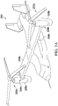
- FIG. 2A illustrates a tiltrotor aircraft 200 that utilizes the system in accordance with the present application.
- Tiltrotor aircraft 200 includes rotor assemblies 202a and 202b that are carried by wings 204a and 204b, and are disposed at end portions 206a and 206b of wings 204a and 204b, respectively.
- Rotor assemblies 202a and 202b include nacelles 208a and 208b, which carry the engines and transmissions of tiltrotor aircraft 200.
- Rotor assemblies 202a and 202b move or rotate relative to wings 204a and 204b between a helicopter or hover mode in which nacelles 208a and 208b are tilted upward, such that tiltrotor aircraft 200 flies like a conventional helicopter; and an airplane or cruise mode in which rotor assemblies 202a and 202b are tilted forward, such that tiltrotor aircraft 200 flies like a conventional propeller driven aircraft.
- FIG. 2B illustrates another tiltrotor aircraft 200 that utilizes the system in accordance with the present application.
- Tiltrotor aircraft 200 includes rotor assemblies 202a and 202b that are carried by wings 204a and 204b, and are disposed at end portions 206a and 206b of wings 204a and 204b, respectively.
- Rotor assemblies 202a and 202b include nacelles 208a and 208b, which include the engines and transmissions of tiltrotor aircraft 200.
- the engines are fixed to the wing and do not rotate, rather, only the pylons 210a and 210b with the rotor assemblies 202a and 202b rotate.
- Pylons 210a and 210b move and rotate relative to wings 204a and 204b and the nacelles 208a and 208b.
- the nacelles 208a and 208b do not more relative to the wings 204a and 204b. Instead, during the transition between a helicopter or hover mode only the pylons 210a and 210b rotate to redirect the thrust from the rotor assemblies 202a and 202b.
- the tiltrotor aircraft 200 is still able to fly like a conventional helicopter; and an airplane or cruise mode in which on the rotors are tilted forward, such that tiltrotor aircraft 200 flies like a conventional propeller driven aircraft.
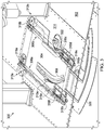
- FIG. 3 shows a support structure 300 for a seat assembly of the present invention.
- Floor 302 of the passenger compartment is shown in relation to the support structure 300, which includes a platform 304 to which a seat (not depicted) is attached and that includes parallel seat adjustment tracks 306a, 306b that permit the user to move and lock the seat along the seat adjustment tracks 306a, 306b forward and rearward.
- a J-shaped track or channel 308 is depicted.
- the J-shaped track or channel 308 is connected to the platform 304 and has a first position generally toward the front of the vehicle in which the seat is an operational position.
- the platform 304 (and seat) When the seat is pushed in a generally rearward direction, the platform 304 (and seat) travels rearward along the straight portion of the J-shaped track or channel 308, and then the platform 304 (and seat) pivots when the platform 304 reaches the curved portion of the J-shaped track or channel 308 toward a second or end position in which the platform 304 (and seat) is in an ingress/egress position.
- the support structure 300 can also include one or more strikers/catches 310a and 310b, which are positioned at the ingress/egress position of the platform 304 such that the strikers/catches 310a and 310b stabilize the platform 304 (and seat) in the ingress/egress position, but also help prevent wear on rollers by providing a releasable catch (strikers/catches 310a and 310b) when the seat is in the ingress/egress position that prevents unnecessary movement of the platform 304 (and seat). Also depicted are a pair of glide and wear plates 312a, 312b attached to the seat assembly substructure 314 and under the platform 304 (and seat).
- Openings 318a, 318b in the seat assembly substructure 314 are connected by a conduit (not depicted) under the surface of the seat assembly substructure 314 for the retaining pins (not depicted) that will lock the seat in the forward/operational position.
- the conduit (not depicted) links both openings 318a, 318b and catches any foreign-object-debris (FOD) going through the openings 318a, 318b, allow the plunger/pin operation even if FOD is present, and allow easy cleaning.
- an extended scuff plate 320 that includes modified rails.
- the extended scuff plate 320 protects, e.g., composite floor panels, and in conjunction with the seat assembly substructure 314, allows for easy screw-on installation of the support structure 300 (e.g., when provided in the form of a kit), which may be used to replace an existing assembly or for new installations.
- a bumper 322 is depicted adjacent the platform 304 that prevent derailments from the J-track at critical transition point (between lateral and forward and aft motion).
- FIG. 4A shows a side view of a seat assembly 400 that includes seat 402, platform 404, seat assembly substructure 406, bumper 408, and release handle assembly 410.
- FIG. 4B is an isometric close-up view of the seat assembly 400 of FIG. 4A .
- Release handle assembly 410 is depicted with a handle 412 and a release/locking mechanism 414 and a forward/rearward seat adjustment handle 420.
- the release/locking mechanism 414 is shown with two cables 416a, 416b that extend to the locking pins (not depicted) that are inserted into openings 424a, 424b in the seat assembly substructure 406 to lock the seat 402 into place at the forward/operational position.
- FIG. 4A and 4B shows height adjustment handle 418, forward/rearward seat adjustment handle 420, and the tracks 422a, 422b, for adjusting the height and the forward/rearward position of the seat 402, respectively.
- FIG. 5 shows a close up, partial cross-sectional view of the locking/release mechanism 500 of the present invention.
- the locking/release mechanism 500 is depicted such that the position of the locking pin 502 (positioned above the opening 504 of the seat assembly substructure 506) is controlled by cable 508 via locking/release mechanism 510.
- a conduit 512 which is below the surface of the seat assembly substructure 506, is designed to capture any FOD going in or around through the opening 504 which allows operation of the locking pin 502 even if FOD is present, and allows easy cleaning.
- the conduit 512 connects two such locking/release mechanisms 500, as shown in FIG. 6 .
- a spring 518 is used to bias the locking pin 502 into the opening 504, which can be locked into the open position via lock 514.
- An indicia (such as a notch, one or more colors, etc.) can be etched, formed, painted or otherwise provided on the locking pin 502 or elsewhere in locking/release mechanism 500 to provide the use a visual indicator that the locking pin 502 is in, out, or both in and out of the opening 504.
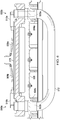
- FIG. 6 shows a side, partial cross-sectional view of the locking/release mechanisms 500a, 500b of the present invention.
- the locking/release mechanisms 500a, 500b are depicted as an isometric, cross-sectional view that shows the locking pins 502a, 502b positioned above the openings 504a, 504b of the seat assembly substructure 506 that is connected to cables 508a, 508b that include locking/release mechanisms 510a, 510b on platform 516.
- the conduit 512 which is below the surface of the seat assembly substructure 506, is designed to capture any FOD going through the openings 504a, 504b, which allow the operation of the locking pins 502a, 502b even if FOD is present, and allow easy cleaning of the FOD.
- the conduit 512 connects two such locking/release mechanisms 500a, 500b and permits the accumulation of FOB between cleanings.
- the words “comprising” (and any form of comprising, such as “comprise” and “comprises"), “having” (and any form of having, such as “have” and “has”), “including” (and any form of including, such as “includes” and “include”) or “containing” (and any form of containing, such as “contains” and “contain”) are inclusive or open-ended and do not exclude additional, unrecited elements or method steps.
- “comprising” may be replaced with “consisting essentially of' or “consisting of'.
- the phrase “consisting essentially of' requires the specified integer(s) or steps as well as those that do not materially affect the character or function of the claimed invention.
- the term “consisting” is used to indicate the presence of the recited integer (e.g., a feature, an element, a characteristic, a property, a method/process step or a limitation) or group of integers (e.g., feature(s), element(s), characteristic(s), propertie(s), method/process steps or limitation(s)) only.
- words of approximation such as, without limitation, "about”, “substantial” or “substantially” refers to a condition that when so modified is understood to not necessarily be absolute or perfect but would be considered close enough to those of ordinary skill in the art to warrant designating the condition as being present.
- the extent to which the description may vary will depend on how great a change can be instituted and still have one of ordinary skilled in the art recognize the modified feature as still having the required characteristics and capabilities of the unmodified feature.
- a numerical value herein that is modified by a word of approximation such as "about” may vary from the stated value by at least ⁇ 1, 2, 3, 4, 5, 6, 7, 10, 12 or 15% from the stated value.
Landscapes
- Engineering & Computer Science (AREA)
- Aviation & Aerospace Engineering (AREA)
- Mechanical Engineering (AREA)
- Transportation (AREA)
- Seats For Vehicles (AREA)
Claims (15)
- Bewegbare Sitzanordnung (400), umfassend:erste und zweite vorbestimmte Pfade, lokalisiert auf einem Boden (302) eines Fahrzeugs (100; 200), wobei jeder Pfad einen Betriebsstandort an einem ersten Ende und einen Eingangs-/Ausgangsstandort an einem zweiten Ende hat, wobei die ersten und zweiten vorbestimmten Pfade einen im Wesentlichen geraden Abschnitt und einen gekrümmten Abschnitt haben;einen Sitz (402), verschiebbar verbunden mit den ersten und zweiten vorbestimmten Pfaden und der Translation zwischen dem ersten und zweiten Ende befähigt;zwei oder mehr Öffnungen (318a, 318b) auf dem Boden (302) des Fahrzeugs (100, 200) auf oder um die ersten und zweiten vorbestimmten Pfade, die eine Verriegelungsposition für den Sitz (402) bereitstellen;ein Kanalsystem (512) unter der Oberfläche des Bodens (302), das zwei oder mehr Öffnungen (318a, 318b) verbindet, wobei das Kanalsystem (512) angeordnet ist, um Fremdkörperrückstände einzufangen und zu akkumulieren durch die zwei oder mehr Öffnungen (318a, 318b) von über der Oberfläche des Bodens (302) zu unter der Oberfläche des Bodens (302); undmindestens einen Verrieglungsstift/-bolzen (502), verbunden mit dem Sitz (402) und befähigt, die zwei oder mehr Öffnungen (318a, 318b) in Eingriff zu nehmen, um den Sitz (402) an Ort und Stelle an dem ersten Ende zu verriegeln.
- Drehflügler (100, 200), umfassend eine bewegbare Sitzanordnung (400) nach Anspruch 1, wobei der Drehflügler (100, 200) umfasst:eine Bedienerkabine, die einen Boden (302) hat; undwobei die bewegbare Sitzanordnung (400) eine Montageplatte umfasst, die die ersten und zweiten vorbestimmten Pfade umfasst.
- Bewegbare Sitzanordnung (400) nach Anspruch 1, wobei der Sitz (402) mit den ersten und zweiten vorbestimmten Pfaden (308) gekuppelt ist mittels einer Vielzahl von Kupplungen, frei orientierbaren Kupplungen, oder beschränkt rotierbaren Kupplungen.
- Bewegbare Sitzanordnung (400) nach Anspruch 1, wobei der Verriegelungsstift/- bolzen (502) selektiv betrieben wird mittels eines Handgriffs (412), verbunden mit dem Verriegelungsstift/-bolzen (502), wobei der Handgriff (412) unterhalb des Sitzes (402), benachbart zu dem Sitz (402), oberhalb des Sitzes (402), auf einer Seite des Sitzes (402) oder einer Sitzrückseite, auf Armlehnen des Sitzes (402) oder hinter dem Sitz (402) lokalisiert ist; oder
der Drehflügler (100, 200) nach Anspruch 2, wobei der Verriegelungsstift/- bolzen (502) selektiv betrieben wird mittels eines Handgriffs (412), verbunden mit dem Verriegelungsstift/-bolzen (502), wobei der Handgriff (412) unterhalb des Sitzes (402), einem Standort benachbart zu dem Sitz (402), einem Standort oberhalb des Sitzes (402), einem Standort auf einer Seite des Sitzes (402) oder einer Sitzrückseite, auf Armlehnen des Sitzes (402) oder einem Standort hinter dem Sitz (402) lokalisiert ist. - Bewegbare Sitzanordnung (400) nach Anspruch 1, Anspruch 3 oder Anspruch 4, oder der Drehflügler (100, 200) nach Anspruch 2 oder Anspruch 4, weiter umfassend einen Reiseassistenzmechanismus, um in dem Translatieren des Sitzes (402) zwischen dem Betriebsstandort und dem Eingangs-/Ausgangsstandort zu assistieren.
- Bewegbare Sitzanordnung (400) nach einem vorstehenden Anordnungs-Anspruch, oder der Drehflügler (100, 200) nach einem vorstehenden Drehflügler-Anspruch, wobei der Verriegelungsstift/-bolzen (502) aus einer Gruppe ausgewählt wird, die besteht aus: einem mechanischen Mechanismus, einem federartigen Mechanismus, einem elektrischen Mechanismus, einem hydraulischen Mechanismus, einem pneumatischen Mechanismus, einem magnetischen Mechanismus, einem elektro-hydraulischen Mechanismus, einem elektropneumatischen Mechanismus, oder einem elektro-magnetischen Mechanismus.
- Bewegbare Sitzanordnung (400) nach einem vorstehenden Anordnungs-Anspruch, oder der Drehflügler (100, 200) nach einem vorstehenden Drehflügler-Anspruch, weiter umfassend einen positiven Fanghaken, der positioniert ist, um lösbar den Sitz (402) an dem Eingangs-/Ausgangsstandort zurückzuhalten.
- Bewegbare Sitzanordnung (400) nach einem vorstehenden Anordnungs-Anspruch oder der Drehflügler (100, 200) nach einem vorstehenden Drehflügler-Anspruch, weiter umfassend zwei oder mehr Gleit- oder Verschleißplatten (312a, 312b), die mindestens eines aus: mindestens einen Teil eines Gewichts des Sitzes (402) stützen, um Verschleiß auf den ersten und zweiten vorbestimmten Pfaden zu reduzieren oder dem Sitz (402) Stabilität hinzuzufügen, während er entlang des vorbestimmten Pfades reist.
- Bewegbare Sitzanordnung (400) nach einem vorstehenden Anordnungs-Anspruch, oder ein Drehflügler (100, 200) nach einem vorstehenden Drehflügler-Anspruch, weiter umfassend einen oder mehrere Stoßfänger (322, 408) oder Fanghaken, befestigt an dem Boden (302), die mindestens eines aus: Entgleisung des Sitzes (402) auf den ersten und zweiten vorbestimmten Pfaden an einem Übergang zwischen dem im Wesentlichen geraden Abschnitt und einem gekrümmten Abschnitt verhindern oder einen Eingangs-/Ausgangsschlagfanghaken, der den Sitz (402) an dem Eingangs-/Ausgangstandort stabilisiert.
- Bewegbare Sitzanordnung (400) nach einem vorstehenden Anordnungs-Anspruch, oder der Drehflügler (100, 200) nach einem vorstehenden Drehflügler-Anspruch, weiter umfassend eine Scheuerplatte (320), die sich um mindestens eine Kante des Bodens (302) erstreckt, benachbart zu dem Sitz (402), um Schaden des Bodens (302) während des Betriebs des Fahrzeugs (100; 200) oder während Eingangs-/Ausgangs dem Sitz (402) fernzuhalten.
- Bewegbare Sitzanordnung (400) nach einem vorstehenden Anordnungs-Anspruch, oder der Drehflügler (100, 200) nach einem vorstehenden Drehflügler-Anspruch, wobei das Kanalsystem (512) entfernbar ist.
- Bewegbare Sitzanordnung (400) nach einem vorstehenden Anordnungs-Anspruch oder der Drehflügler (100, 200) nach einem vorstehenden Drehflügler-Anspruch, wobei der Verriegelungsstift/-bolzen (502) weiter Anzeigen umfasst, die zeigen, falls der Verriegelungsstift/-bolzen (502) in einer verriegelten oder einer unverriegelten Position ist.
- Bewegbare Sitzanordnung (400) nach einem vorstehenden Anordnungs-Anspruch, oder der Drehfügler (100, 200) nach einem vorstehenden Luftfahrzeug-Anspruch, wobei der Verrieglungsstift/-bolzen (502) federbelastet ist, und wobei der Verriegelungsstift/-bolzen (502) mit einem Bowden-Kabel oder einer Druck-ZugStange betrieben wird.
- Bausatz für eine bewegbare Sitzanordnung (400) für ein Fahrzeug (100, 200), umfassend:
eine Montageplatte für einen Sitz (402), umfassend:erste und zweite vorbestimmte Pfade, lokalisiert auf einem Boden (302) des Fahrzeugs (100, 200), wobei jeder Pfad einen Betriebsstandort an einem ersten Ende und einen Eingangs-/Ausgansstandort an einem zweiten Ende hat, wobei die ersten und zweiten vorbestimmten Pfade einen im Wesentlichen geraden Abschnitt und einen gekrümmten Abschnitt haben;zwei oder mehr Öffnungen (318a, 318b) auf dem Boden (302) des Fahrzeugs (100, 200) auf oder um die ersten und zweiten vorbestimmten Pfade, die eine Verriegelungsposition für den Sitz (402) bereitstellen;ein Kanalsystem (512) unter der Oberfläche des Bodens (302), das zwei oder mehr Öffnungen (318a, 318b) verbindet, wobei das Kanalsystem (512) angeordnet ist, um Fremdkörperrückstände einzufangen und zu akkumulieren durch die zwei oder mehr Öffnungen (318a, 318b) von über der Oberfläche des Bodens (302) zu unter der Oberfläche des Bodens (302); undAnweisungen zur Installation der bewegbaren Sitzanordnung (400). - Verfahren zum Bereitstellen einer verbesserten Sitzanordnung (400), umfassend:Bereitstellen erster und zweiter vorbestimmter Pfade, lokalisiert auf einem Boden (302) eines Fahrzeugs (100, 200), wobei jeder Pfad einen Betriebsstandort an einem ersten Ende und einen Eingangs-/Ausgangsstandort an einem zweiten Ende hat, wobei die ersten und zweiten vorbestimmten Pfade einen im Wesentlichen geraden Abschnitt und einen gekrümmten Abschnitt haben;verschiebbar Befestigen eines Sitzes (402) mit den ersten und zweiten vorbestimmten Pfaden und der Translation zwischen einer ersten und einer zweiten Position befähigt;Bereitstellen von zwei oder mehr Öffnungen (318a, 318b) auf dem Boden (302) des Fahrzeugs (100, 200) auf oder um die ersten und zweien vorbestimmten Pfade, die eine Verriegelungsposition für den Sitz (402) bereitstellen;Bereitstellen eines Kanalsystems (512) unter der Oberfläche des Bodens (302), das zwei oder mehr Öffnungen (318a, 318b) verbindet, wobei das Kanalsystem (512) angeordnet ist, um Fremdkörperrückstände einzufangen und zu akkumulieren durch die zwei oder mehr Öffnungen (318a, 318b) von über der Oberfläche des Bodens (302) zu unter der Oberfläche des Bodens (302); undBereitstellen mindestens eines Verrieglungsstifts/-bolzens (502), verbunden mit dem Sitz (402) und befähigt, die zwei oder mehr Öffnungen (318a, 318b) in Eingriff zu nehmen, um den Sitz (402) an Ort und Stelle entlang der ersten und zweiten vorbestimmten Pfade zu verriegeln.
Applications Claiming Priority (1)
| Application Number | Priority Date | Filing Date | Title |
|---|---|---|---|
| US15/484,724 US10611485B2 (en) | 2017-04-11 | 2017-04-11 | Seat assembly using J-track seats |
Publications (2)
| Publication Number | Publication Date |
|---|---|
| EP3388342A1 EP3388342A1 (de) | 2018-10-17 |
| EP3388342B1 true EP3388342B1 (de) | 2019-07-17 |
Family
ID=58745120
Family Applications (1)
| Application Number | Title | Priority Date | Filing Date |
|---|---|---|---|
| EP17172046.9A Active EP3388342B1 (de) | 2017-04-11 | 2017-05-19 | Sitzanordnung mit j-track-sitzen |
Country Status (2)
| Country | Link |
|---|---|
| US (1) | US10611485B2 (de) |
| EP (1) | EP3388342B1 (de) |
Families Citing this family (6)
| Publication number | Priority date | Publication date | Assignee | Title |
|---|---|---|---|---|
| US11059589B2 (en) * | 2018-08-03 | 2021-07-13 | B/E Aerospace, Inc. | Three-place berthing aircraft divan |
| US11413987B2 (en) * | 2019-09-03 | 2022-08-16 | The Boeing Company | Electromagnetic seat attachment and seat power |
| US12428162B2 (en) * | 2022-07-25 | 2025-09-30 | Ami Industries, Inc. | Motion control system for an aircraft seat |
| US12497190B2 (en) | 2023-07-14 | 2025-12-16 | Textron Innovations Inc. | Automatic retractable center console system for an aircraft |
| US12269600B2 (en) * | 2023-07-26 | 2025-04-08 | Ami Industries, Inc. | Breakover vehicle operator seat convertible to non-breakover configuration |
| US12269599B2 (en) | 2023-07-26 | 2025-04-08 | Ami Industries, Inc. | Aircraft seat with double shear track fitting assembly |
Family Cites Families (7)
| Publication number | Priority date | Publication date | Assignee | Title |
|---|---|---|---|---|
| US2563220A (en) * | 1946-03-04 | 1951-08-07 | Briggs Mfg Co | Seat structure |
| JPS5914578A (ja) * | 1982-07-15 | 1984-01-25 | Nissan Motor Co Ltd | 自動車のフロア構造 |
| US6027170A (en) * | 1999-02-19 | 2000-02-22 | Paccar Inc | Rotating vehicle seat |
| US6794013B1 (en) * | 2000-10-30 | 2004-09-21 | Rally Manufacturing, Inc. | Heavy duty vehicle floor mat |
| TWM252584U (en) * | 2004-02-13 | 2004-12-11 | Pro Glory Entpr Co Ltd | A rotation mechanism for vehicle seat |
| US8231097B2 (en) * | 2009-09-11 | 2012-07-31 | Ami Industries, Inc. | Aircraft equipment support |
| US8857763B2 (en) * | 2012-01-27 | 2014-10-14 | Bell Helicopter Textron Inc. | Vehicle crewstation seat assembly |
-
2017
- 2017-04-11 US US15/484,724 patent/US10611485B2/en active Active
- 2017-05-19 EP EP17172046.9A patent/EP3388342B1/de active Active
Non-Patent Citations (1)
| Title |
|---|
| None * |
Also Published As
| Publication number | Publication date |
|---|---|
| US10611485B2 (en) | 2020-04-07 |
| US20180290751A1 (en) | 2018-10-11 |
| EP3388342A1 (de) | 2018-10-17 |
Similar Documents
| Publication | Publication Date | Title |
|---|---|---|
| US10611485B2 (en) | Seat assembly using J-track seats | |
| CN103223882B (zh) | 运载工具驾驶室座椅组件 | |
| US11142321B2 (en) | Aircraft door and privacy panel assemblies | |
| EP2877399B1 (de) | Schiebersitz für flugzeug | |
| US11338922B2 (en) | Tracking base assembly for aircraft seat | |
| US12234017B2 (en) | Redundant rail and carriage assembly | |
| US10676194B2 (en) | Contoured class divider | |
| US11597492B2 (en) | Sliding door | |
| EP2818412B1 (de) | Installationsverfahren für eine flugzeugtoiletteneinheit und entsprechendes flugzeug | |
| US11161614B2 (en) | Vehicle business class seat and stowage system | |
| JP2007509790A (ja) | ダクテッドファン垂直離着陸機 | |
| US12344388B2 (en) | Propulsion assembly for an aircraft, comprising a load bearer | |
| US6487743B1 (en) | Y-bridge airplane passenger gateway | |
| US6382562B1 (en) | AFT egress and control device for an aircraft | |
| EP4353589B1 (de) | Versetzter hubschrauberpilotsitz mit zentriertem vertikalbewegungssystem | |
| US12522361B2 (en) | Recline lockout device for aircraft seat | |
| US12391401B2 (en) | Seat mounted inboard flight controllers for aircraft pilot seats | |
| US11608177B2 (en) | Aircraft passenger seat row with cabin attendant seat | |
| US12134476B1 (en) | Flight controller ingress and egress system | |
| US11530023B2 (en) | Aircraft emergency door and method of operating the same | |
| CN107757862B (zh) | 具有能相对于机身转动和平移的整流罩的旋翼飞行器 |
Legal Events
| Date | Code | Title | Description |
|---|---|---|---|
| STAA | Information on the status of an ep patent application or granted ep patent |
Free format text: STATUS: EXAMINATION IS IN PROGRESS |
|
| PUAI | Public reference made under article 153(3) epc to a published international application that has entered the european phase |
Free format text: ORIGINAL CODE: 0009012 |
|
| 17P | Request for examination filed |
Effective date: 20170519 |
|
| AK | Designated contracting states |
Kind code of ref document: A1 Designated state(s): AL AT BE BG CH CY CZ DE DK EE ES FI FR GB GR HR HU IE IS IT LI LT LU LV MC MK MT NL NO PL PT RO RS SE SI SK SM TR |
|
| AX | Request for extension of the european patent |
Extension state: BA ME |
|
| GRAP | Despatch of communication of intention to grant a patent |
Free format text: ORIGINAL CODE: EPIDOSNIGR1 |
|
| STAA | Information on the status of an ep patent application or granted ep patent |
Free format text: STATUS: GRANT OF PATENT IS INTENDED |
|
| INTG | Intention to grant announced |
Effective date: 20181127 |
|
| GRAS | Grant fee paid |
Free format text: ORIGINAL CODE: EPIDOSNIGR3 |
|
| GRAJ | Information related to disapproval of communication of intention to grant by the applicant or resumption of examination proceedings by the epo deleted |
Free format text: ORIGINAL CODE: EPIDOSDIGR1 |
|
| GRAL | Information related to payment of fee for publishing/printing deleted |
Free format text: ORIGINAL CODE: EPIDOSDIGR3 |
|
| STAA | Information on the status of an ep patent application or granted ep patent |
Free format text: STATUS: EXAMINATION IS IN PROGRESS |
|
| GRAR | Information related to intention to grant a patent recorded |
Free format text: ORIGINAL CODE: EPIDOSNIGR71 |
|
| STAA | Information on the status of an ep patent application or granted ep patent |
Free format text: STATUS: GRANT OF PATENT IS INTENDED |
|
| INTC | Intention to grant announced (deleted) | ||
| INTG | Intention to grant announced |
Effective date: 20190307 |
|
| GRAA | (expected) grant |
Free format text: ORIGINAL CODE: 0009210 |
|
| STAA | Information on the status of an ep patent application or granted ep patent |
Free format text: STATUS: THE PATENT HAS BEEN GRANTED |
|
| AK | Designated contracting states |
Kind code of ref document: B1 Designated state(s): AL AT BE BG CH CY CZ DE DK EE ES FI FR GB GR HR HU IE IS IT LI LT LU LV MC MK MT NL NO PL PT RO RS SE SI SK SM TR |
|
| REG | Reference to a national code |
Ref country code: GB Ref legal event code: FG4D |
|
| REG | Reference to a national code |
Ref country code: CH Ref legal event code: EP |
|
| REG | Reference to a national code |
Ref country code: IE Ref legal event code: FG4D |
|
| REG | Reference to a national code |
Ref country code: DE Ref legal event code: R096 Ref document number: 602017005289 Country of ref document: DE |
|
| REG | Reference to a national code |
Ref country code: AT Ref legal event code: REF Ref document number: 1155636 Country of ref document: AT Kind code of ref document: T Effective date: 20190815 |
|
| REG | Reference to a national code |
Ref country code: NL Ref legal event code: MP Effective date: 20190717 |
|
| REG | Reference to a national code |
Ref country code: LT Ref legal event code: MG4D |
|
| REG | Reference to a national code |
Ref country code: AT Ref legal event code: MK05 Ref document number: 1155636 Country of ref document: AT Kind code of ref document: T Effective date: 20190717 |
|
| PG25 | Lapsed in a contracting state [announced via postgrant information from national office to epo] |
Ref country code: FI Free format text: LAPSE BECAUSE OF FAILURE TO SUBMIT A TRANSLATION OF THE DESCRIPTION OR TO PAY THE FEE WITHIN THE PRESCRIBED TIME-LIMIT Effective date: 20190717 Ref country code: SE Free format text: LAPSE BECAUSE OF FAILURE TO SUBMIT A TRANSLATION OF THE DESCRIPTION OR TO PAY THE FEE WITHIN THE PRESCRIBED TIME-LIMIT Effective date: 20190717 Ref country code: AT Free format text: LAPSE BECAUSE OF FAILURE TO SUBMIT A TRANSLATION OF THE DESCRIPTION OR TO PAY THE FEE WITHIN THE PRESCRIBED TIME-LIMIT Effective date: 20190717 Ref country code: NL Free format text: LAPSE BECAUSE OF FAILURE TO SUBMIT A TRANSLATION OF THE DESCRIPTION OR TO PAY THE FEE WITHIN THE PRESCRIBED TIME-LIMIT Effective date: 20190717 Ref country code: NO Free format text: LAPSE BECAUSE OF FAILURE TO SUBMIT A TRANSLATION OF THE DESCRIPTION OR TO PAY THE FEE WITHIN THE PRESCRIBED TIME-LIMIT Effective date: 20191017 Ref country code: PT Free format text: LAPSE BECAUSE OF FAILURE TO SUBMIT A TRANSLATION OF THE DESCRIPTION OR TO PAY THE FEE WITHIN THE PRESCRIBED TIME-LIMIT Effective date: 20191118 Ref country code: BG Free format text: LAPSE BECAUSE OF FAILURE TO SUBMIT A TRANSLATION OF THE DESCRIPTION OR TO PAY THE FEE WITHIN THE PRESCRIBED TIME-LIMIT Effective date: 20191017 Ref country code: HR Free format text: LAPSE BECAUSE OF FAILURE TO SUBMIT A TRANSLATION OF THE DESCRIPTION OR TO PAY THE FEE WITHIN THE PRESCRIBED TIME-LIMIT Effective date: 20190717 Ref country code: LT Free format text: LAPSE BECAUSE OF FAILURE TO SUBMIT A TRANSLATION OF THE DESCRIPTION OR TO PAY THE FEE WITHIN THE PRESCRIBED TIME-LIMIT Effective date: 20190717 |
|
| PG25 | Lapsed in a contracting state [announced via postgrant information from national office to epo] |
Ref country code: AL Free format text: LAPSE BECAUSE OF FAILURE TO SUBMIT A TRANSLATION OF THE DESCRIPTION OR TO PAY THE FEE WITHIN THE PRESCRIBED TIME-LIMIT Effective date: 20190717 Ref country code: LV Free format text: LAPSE BECAUSE OF FAILURE TO SUBMIT A TRANSLATION OF THE DESCRIPTION OR TO PAY THE FEE WITHIN THE PRESCRIBED TIME-LIMIT Effective date: 20190717 Ref country code: ES Free format text: LAPSE BECAUSE OF FAILURE TO SUBMIT A TRANSLATION OF THE DESCRIPTION OR TO PAY THE FEE WITHIN THE PRESCRIBED TIME-LIMIT Effective date: 20190717 Ref country code: IS Free format text: LAPSE BECAUSE OF FAILURE TO SUBMIT A TRANSLATION OF THE DESCRIPTION OR TO PAY THE FEE WITHIN THE PRESCRIBED TIME-LIMIT Effective date: 20191117 Ref country code: RS Free format text: LAPSE BECAUSE OF FAILURE TO SUBMIT A TRANSLATION OF THE DESCRIPTION OR TO PAY THE FEE WITHIN THE PRESCRIBED TIME-LIMIT Effective date: 20190717 Ref country code: GR Free format text: LAPSE BECAUSE OF FAILURE TO SUBMIT A TRANSLATION OF THE DESCRIPTION OR TO PAY THE FEE WITHIN THE PRESCRIBED TIME-LIMIT Effective date: 20191018 |
|
| PG25 | Lapsed in a contracting state [announced via postgrant information from national office to epo] |
Ref country code: TR Free format text: LAPSE BECAUSE OF FAILURE TO SUBMIT A TRANSLATION OF THE DESCRIPTION OR TO PAY THE FEE WITHIN THE PRESCRIBED TIME-LIMIT Effective date: 20190717 |
|
| PG25 | Lapsed in a contracting state [announced via postgrant information from national office to epo] |
Ref country code: RO Free format text: LAPSE BECAUSE OF FAILURE TO SUBMIT A TRANSLATION OF THE DESCRIPTION OR TO PAY THE FEE WITHIN THE PRESCRIBED TIME-LIMIT Effective date: 20190717 Ref country code: PL Free format text: LAPSE BECAUSE OF FAILURE TO SUBMIT A TRANSLATION OF THE DESCRIPTION OR TO PAY THE FEE WITHIN THE PRESCRIBED TIME-LIMIT Effective date: 20190717 Ref country code: DK Free format text: LAPSE BECAUSE OF FAILURE TO SUBMIT A TRANSLATION OF THE DESCRIPTION OR TO PAY THE FEE WITHIN THE PRESCRIBED TIME-LIMIT Effective date: 20190717 Ref country code: EE Free format text: LAPSE BECAUSE OF FAILURE TO SUBMIT A TRANSLATION OF THE DESCRIPTION OR TO PAY THE FEE WITHIN THE PRESCRIBED TIME-LIMIT Effective date: 20190717 |
|
| PG25 | Lapsed in a contracting state [announced via postgrant information from national office to epo] |
Ref country code: CZ Free format text: LAPSE BECAUSE OF FAILURE TO SUBMIT A TRANSLATION OF THE DESCRIPTION OR TO PAY THE FEE WITHIN THE PRESCRIBED TIME-LIMIT Effective date: 20190717 Ref country code: SM Free format text: LAPSE BECAUSE OF FAILURE TO SUBMIT A TRANSLATION OF THE DESCRIPTION OR TO PAY THE FEE WITHIN THE PRESCRIBED TIME-LIMIT Effective date: 20190717 Ref country code: IS Free format text: LAPSE BECAUSE OF FAILURE TO SUBMIT A TRANSLATION OF THE DESCRIPTION OR TO PAY THE FEE WITHIN THE PRESCRIBED TIME-LIMIT Effective date: 20200224 Ref country code: SK Free format text: LAPSE BECAUSE OF FAILURE TO SUBMIT A TRANSLATION OF THE DESCRIPTION OR TO PAY THE FEE WITHIN THE PRESCRIBED TIME-LIMIT Effective date: 20190717 |
|
| REG | Reference to a national code |
Ref country code: DE Ref legal event code: R097 Ref document number: 602017005289 Country of ref document: DE |
|
| PLBE | No opposition filed within time limit |
Free format text: ORIGINAL CODE: 0009261 |
|
| STAA | Information on the status of an ep patent application or granted ep patent |
Free format text: STATUS: NO OPPOSITION FILED WITHIN TIME LIMIT |
|
| PG2D | Information on lapse in contracting state deleted |
Ref country code: IS |
|
| 26N | No opposition filed |
Effective date: 20200603 |
|
| PG25 | Lapsed in a contracting state [announced via postgrant information from national office to epo] |
Ref country code: SI Free format text: LAPSE BECAUSE OF FAILURE TO SUBMIT A TRANSLATION OF THE DESCRIPTION OR TO PAY THE FEE WITHIN THE PRESCRIBED TIME-LIMIT Effective date: 20190717 |
|
| PG25 | Lapsed in a contracting state [announced via postgrant information from national office to epo] |
Ref country code: MC Free format text: LAPSE BECAUSE OF FAILURE TO SUBMIT A TRANSLATION OF THE DESCRIPTION OR TO PAY THE FEE WITHIN THE PRESCRIBED TIME-LIMIT Effective date: 20190717 Ref country code: LI Free format text: LAPSE BECAUSE OF NON-PAYMENT OF DUE FEES Effective date: 20200531 Ref country code: CH Free format text: LAPSE BECAUSE OF NON-PAYMENT OF DUE FEES Effective date: 20200531 |
|
| REG | Reference to a national code |
Ref country code: BE Ref legal event code: MM Effective date: 20200531 |
|
| PG25 | Lapsed in a contracting state [announced via postgrant information from national office to epo] |
Ref country code: LU Free format text: LAPSE BECAUSE OF NON-PAYMENT OF DUE FEES Effective date: 20200519 |
|
| PG25 | Lapsed in a contracting state [announced via postgrant information from national office to epo] |
Ref country code: IE Free format text: LAPSE BECAUSE OF NON-PAYMENT OF DUE FEES Effective date: 20200519 |
|
| PG25 | Lapsed in a contracting state [announced via postgrant information from national office to epo] |
Ref country code: BE Free format text: LAPSE BECAUSE OF NON-PAYMENT OF DUE FEES Effective date: 20200531 |
|
| PG25 | Lapsed in a contracting state [announced via postgrant information from national office to epo] |
Ref country code: MT Free format text: LAPSE BECAUSE OF FAILURE TO SUBMIT A TRANSLATION OF THE DESCRIPTION OR TO PAY THE FEE WITHIN THE PRESCRIBED TIME-LIMIT Effective date: 20190717 Ref country code: CY Free format text: LAPSE BECAUSE OF FAILURE TO SUBMIT A TRANSLATION OF THE DESCRIPTION OR TO PAY THE FEE WITHIN THE PRESCRIBED TIME-LIMIT Effective date: 20190717 |
|
| PG25 | Lapsed in a contracting state [announced via postgrant information from national office to epo] |
Ref country code: MK Free format text: LAPSE BECAUSE OF FAILURE TO SUBMIT A TRANSLATION OF THE DESCRIPTION OR TO PAY THE FEE WITHIN THE PRESCRIBED TIME-LIMIT Effective date: 20190717 |
|
| P01 | Opt-out of the competence of the unified patent court (upc) registered |
Effective date: 20230602 |
|
| PGFP | Annual fee paid to national office [announced via postgrant information from national office to epo] |
Ref country code: DE Payment date: 20250529 Year of fee payment: 9 |
|
| PGFP | Annual fee paid to national office [announced via postgrant information from national office to epo] |
Ref country code: GB Payment date: 20250527 Year of fee payment: 9 |
|
| PGFP | Annual fee paid to national office [announced via postgrant information from national office to epo] |
Ref country code: IT Payment date: 20250521 Year of fee payment: 9 |
|
| PGFP | Annual fee paid to national office [announced via postgrant information from national office to epo] |
Ref country code: FR Payment date: 20250526 Year of fee payment: 9 |