EP3388255A1 - Pneumatic tire - Google Patents
Pneumatic tire Download PDFInfo
- Publication number
- EP3388255A1 EP3388255A1 EP18152439.8A EP18152439A EP3388255A1 EP 3388255 A1 EP3388255 A1 EP 3388255A1 EP 18152439 A EP18152439 A EP 18152439A EP 3388255 A1 EP3388255 A1 EP 3388255A1
- Authority
- EP
- European Patent Office
- Prior art keywords
- groove
- tire
- slanted
- main groove
- tread
- Prior art date
- Legal status (The legal status is an assumption and is not a legal conclusion. Google has not performed a legal analysis and makes no representation as to the accuracy of the status listed.)
- Granted
Links
Images




Classifications
-
- B—PERFORMING OPERATIONS; TRANSPORTING
- B60—VEHICLES IN GENERAL
- B60C—VEHICLE TYRES; TYRE INFLATION; TYRE CHANGING; CONNECTING VALVES TO INFLATABLE ELASTIC BODIES IN GENERAL; DEVICES OR ARRANGEMENTS RELATED TO TYRES
- B60C11/00—Tyre tread bands; Tread patterns; Anti-skid inserts
- B60C11/03—Tread patterns
- B60C11/0302—Tread patterns directional pattern, i.e. with main rolling direction
-
- B—PERFORMING OPERATIONS; TRANSPORTING
- B60—VEHICLES IN GENERAL
- B60C—VEHICLE TYRES; TYRE INFLATION; TYRE CHANGING; CONNECTING VALVES TO INFLATABLE ELASTIC BODIES IN GENERAL; DEVICES OR ARRANGEMENTS RELATED TO TYRES
- B60C11/00—Tyre tread bands; Tread patterns; Anti-skid inserts
- B60C11/03—Tread patterns
- B60C11/0306—Patterns comprising block rows or discontinuous ribs
-
- B—PERFORMING OPERATIONS; TRANSPORTING
- B60—VEHICLES IN GENERAL
- B60C—VEHICLE TYRES; TYRE INFLATION; TYRE CHANGING; CONNECTING VALVES TO INFLATABLE ELASTIC BODIES IN GENERAL; DEVICES OR ARRANGEMENTS RELATED TO TYRES
- B60C11/00—Tyre tread bands; Tread patterns; Anti-skid inserts
- B60C11/03—Tread patterns
- B60C11/0327—Tread patterns characterised by special properties of the tread pattern
- B60C11/0332—Tread patterns characterised by special properties of the tread pattern by the footprint-ground contacting area of the tyre tread
-
- B—PERFORMING OPERATIONS; TRANSPORTING
- B60—VEHICLES IN GENERAL
- B60C—VEHICLE TYRES; TYRE INFLATION; TYRE CHANGING; CONNECTING VALVES TO INFLATABLE ELASTIC BODIES IN GENERAL; DEVICES OR ARRANGEMENTS RELATED TO TYRES
- B60C11/00—Tyre tread bands; Tread patterns; Anti-skid inserts
- B60C11/03—Tread patterns
- B60C11/12—Tread patterns characterised by the use of narrow slits or incisions, e.g. sipes
- B60C11/1236—Tread patterns characterised by the use of narrow slits or incisions, e.g. sipes with special arrangements in the tread pattern
-
- B—PERFORMING OPERATIONS; TRANSPORTING
- B60—VEHICLES IN GENERAL
- B60C—VEHICLE TYRES; TYRE INFLATION; TYRE CHANGING; CONNECTING VALVES TO INFLATABLE ELASTIC BODIES IN GENERAL; DEVICES OR ARRANGEMENTS RELATED TO TYRES
- B60C11/00—Tyre tread bands; Tread patterns; Anti-skid inserts
- B60C11/03—Tread patterns
- B60C2011/0337—Tread patterns characterised by particular design features of the pattern
- B60C2011/0339—Grooves
- B60C2011/0341—Circumferential grooves
-
- B—PERFORMING OPERATIONS; TRANSPORTING
- B60—VEHICLES IN GENERAL
- B60C—VEHICLE TYRES; TYRE INFLATION; TYRE CHANGING; CONNECTING VALVES TO INFLATABLE ELASTIC BODIES IN GENERAL; DEVICES OR ARRANGEMENTS RELATED TO TYRES
- B60C11/00—Tyre tread bands; Tread patterns; Anti-skid inserts
- B60C11/03—Tread patterns
- B60C2011/0337—Tread patterns characterised by particular design features of the pattern
- B60C2011/0339—Grooves
- B60C2011/0358—Lateral grooves, i.e. having an angle of 45 to 90 degees to the equatorial plane
- B60C2011/0372—Lateral grooves, i.e. having an angle of 45 to 90 degees to the equatorial plane with particular inclination angles
-
- B—PERFORMING OPERATIONS; TRANSPORTING
- B60—VEHICLES IN GENERAL
- B60C—VEHICLE TYRES; TYRE INFLATION; TYRE CHANGING; CONNECTING VALVES TO INFLATABLE ELASTIC BODIES IN GENERAL; DEVICES OR ARRANGEMENTS RELATED TO TYRES
- B60C11/00—Tyre tread bands; Tread patterns; Anti-skid inserts
- B60C11/03—Tread patterns
- B60C2011/0337—Tread patterns characterised by particular design features of the pattern
- B60C2011/0339—Grooves
- B60C2011/0374—Slant grooves, i.e. having an angle of about 5 to 35 degrees to the equatorial plane
-
- B—PERFORMING OPERATIONS; TRANSPORTING
- B60—VEHICLES IN GENERAL
- B60C—VEHICLE TYRES; TYRE INFLATION; TYRE CHANGING; CONNECTING VALVES TO INFLATABLE ELASTIC BODIES IN GENERAL; DEVICES OR ARRANGEMENTS RELATED TO TYRES
- B60C11/00—Tyre tread bands; Tread patterns; Anti-skid inserts
- B60C11/03—Tread patterns
- B60C2011/0337—Tread patterns characterised by particular design features of the pattern
- B60C2011/0339—Grooves
- B60C2011/0381—Blind or isolated grooves
-
- B—PERFORMING OPERATIONS; TRANSPORTING
- B60—VEHICLES IN GENERAL
- B60C—VEHICLE TYRES; TYRE INFLATION; TYRE CHANGING; CONNECTING VALVES TO INFLATABLE ELASTIC BODIES IN GENERAL; DEVICES OR ARRANGEMENTS RELATED TO TYRES
- B60C11/00—Tyre tread bands; Tread patterns; Anti-skid inserts
- B60C11/03—Tread patterns
- B60C2011/0337—Tread patterns characterised by particular design features of the pattern
- B60C2011/0386—Continuous ribs
- B60C2011/0388—Continuous ribs provided at the equatorial plane
Definitions
- the present invention relates to a pneumatic tire that can effectively inhibit a hydroplaning phenomenon while maintaining steering stability on a dry road surface and performance on snow.
- Japanese Laid-Open Patent Publication No. 2016-196288 has proposed a winter tire.
- a plurality of slanted grooves are provided so as to extend obliquely from each tread edge toward the tire equator side, and a plurality of slanted land portions are each provided so as to be demarcated between the slanted grooves.
- no main groove extending continuously in the tire circumferential direction is provided.
- the present invention has been made in view of the above-described problem, and a main object of the present invention is to provide a pneumatic tire that can inhibit a hydroplaning phenomenon while maintaining steering stability on a dry road surface and performance on snow.
- the present invention is directed to a pneumatic tire having a tread portion, wherein: in the tread portion, a main groove is provided so as to extend continuously in a tire circumferential direction between a tire equator and a first tread edge at one side in a tire axial direction, a plurality of slanted grooves are each provided so as to extend obliquely from the first tread edge toward the tire equator side and terminate at a position at the tire equator side beyond the main groove, and a plurality of slanted land portions are each provided so as to be demarcated between the slanted grooves adjacent to each other in the tire circumferential direction; and in at least one of the slanted land portions, a lug groove that is connected at one end thereof to the slanted groove and that terminates at another end thereof within the slanted land portion is provided so as to be adjacent to the main groove.
- the lug groove is preferably provided at the first tread edge side of the main groove.
- the lug groove is preferably slanted in a direction away from the main groove while extending from the one end toward the other end thereof.
- the slanted groove preferably has a larger groove width than the main groove.
- a distance in the tire axial direction from the tire equator to a groove center line of the main groove is preferably 0.10 to 0.20 times of a tread width.
- the maximum ground-contact width W1 is preferably 200 to 250 mm.
- the main groove is provided so as to extend continuously in the tire circumferential direction between the tire equator and the first tread edge at the one side in the tire axial direction
- the plurality of slanted grooves are each provided so as to extend obliquely from the first tread edge toward the tire equator side and terminate at a position at the tire equator side beyond the main groove
- the plurality of slanted land portions are each provided so as to be demarcated between the slanted grooves adjacent to each other in the tire circumferential direction.
- each slanted groove forms a long snow column extending obliquely relative to the tire axial direction and shears the snow column, whereby great on-snow traction can be obtained.
- the lug groove that is connected at one end thereof to the slanted groove and that terminates at another end thereof within the slanted land portion is provided so as to be adjacent to the main groove.
- a lug groove can enhance wet performance and performance on snow while maintaining steering stability on a dry road surface by inhibiting a decrease in the stiffness of the slanted land portion.
- the lug groove adjacent to the main groove allows the slanted land portion to moderately deform, thereby inhibiting clogging of the main groove and the slanted groove with snow during running on snow, whereby excellent performance on snow can be continuously exerted.
- the pneumatic tire according to the present invention can inhibit a hydroplaning phenomenon while maintaining steering stability on a dry road surface and performance on snow.
- FIG. 1 is a development of a tread portion 2 of a pneumatic tire (hereinafter, referred to merely as "tire") 1 according to the present embodiment.
- the tire 1 according to the present embodiment is suitably used, for example, as a winter pneumatic tire for a passenger car.
- the tire 1 can be used, for example, as a heavy duty pneumatic tire.
- the tire 1 according to the present embodiment has a directional pattern for which a rotation direction R is designated.
- the rotation direction R is shown, for example, on each side wall (not shown) by a character or a symbol.
- the tire 1 has the tread portion 2 between a first tread edge Te1 and a second tread edge Te2.
- the tread portion 2 includes a first tread portion 2A between a tire equator C and the first tread edge Te1, and a second tread portion 2B between the tire equator C and the second tread edge Te2.
- each of the first tread edge Te1 and the second tread edge Te2 is a ground contact position at the outermost side in the tire axial direction when a normal load is applied to the tire 1 in a normal state and the tire 1 is brought into contact with a plane at a camber angle of 0°.
- the normal state is a state where the tire is mounted to a normal rim and inflated to a normal internal pressure and no load is applied to the tire.
- dimensions of components of the tire and the like are values measured in the normal state.
- the "normal rim” is a rim that is defined, in a standard system including a standard on which the tire is based, by the standard for each tire, and is, for example, the "standard rim” in the JATMA standard, the "Design Rim” in the TRA standard, or the “Measuring Rim” in the ETRTO standard.
- the "normal internal pressure” is an air pressure that is defined, in a standard system including a standard on which the tire is based, by the standard for each tire, and is the “maximum air pressure” in the JATMA standard, the maximum value indicated in the table "TIRE LOAD LIMITS AT VARIOUS COLD INFLATION PRESSURES" in the TRA standard, or the “INFLATION PRESSURE” in the ETRTO standard.
- the "normal load” is a load that is defined, in a standard system including a standard on which the tire is based, by the standard for each tire, and is the “maximum load capacity" in the JATMA standard, the maximum value indicated in the table "TIRE LOAD LIMITS AT VARIOUS COLD INFLATION PRESSURES" in the TRA standard, or the "LOAD CAPACITY" in the ETRTO standard.
- a main groove 11 is provided in each of the tread portions 2A and 2B so as to extend continuously in the tire circumferential direction, and a plurality of slanted grooves 10 are provided.
- the main groove 11 achieves excellent drainage performance and thus can effectively inhibit a hydroplaning phenomenon.
- the slanted grooves 10 include, for example, first slanted grooves 10A provided in the first tread portion 2A, and second slanted grooves 10B provided in the second tread portion 2B.
- the first slanted grooves 10A extend obliquely from the first tread edge Te1 toward the tire equator C side.
- the second slanted grooves 10B extend obliquely from the second tread edge Te2 toward the tire equator C side.
- the second slanted grooves 10B have substantially the same configuration as the first slanted grooves 10A.
- the configurations of the first slanted grooves 10A can be applied to the second slanted grooves 10B.
- each slanted groove 10 forms a long snow column extending obliquely relative to the tire axial direction and shears the snow column, whereby great on-snow traction can be obtained.
- each of the slanted grooves 10A and 10B is slanted toward the forward side in the rotation direction R while extending from the tread edge Te1 or Te2 toward the tire equator C side.
- the present invention is not limited to such a mode.
- FIG. 2 shows an enlarged view of the first tread portion 2A.
- each slanted groove 10 is preferably curved such that an angle ⁇ 1 of the slanted groove 10 relative to the tire axial direction gradually increases toward the tire equator C side.
- the angle ⁇ 1 is preferably, for example, 25 to 80°.
- Such a slanted groove 10 can exert great snow column shearing force also in the tire axial direction during running on snow.
- the slanted groove 10 terminates at a position at the tire equator C side beyond the main groove 11.
- the slanted groove 10 terminates without traversing the tire equator C.
- a distance L2 in the tire axial direction from an inner end (which means the inner end, in the tire axial direction, of a groove center line, the same applies to the following) of the slanted groove 10 to the tire equator C is preferably, for example, 2.0% to 5.0% of a tread width TW (shown in FIG. 1 , the same applies to the following).
- the tread width TW is the distance in the tire axial direction from the first tread edge Te1 to the second tread edge Te2 in the normal state.
- the slanted groove 10 preferably has, for example, a groove width that gradually increases toward the first tread edge Te1 side. At least a portion of the slanted groove 10 preferably has, for example, a larger groove width than the main groove 11.
- a maximum groove width W2 of the slanted groove 10 is preferably, for example, 5.0% to 9.0% of the tread width TW.
- the depth of the slanted groove 10 is preferably, for example, 7.0 to 11.0 mm.
- the main grooves 11 include, for example, a first main groove 11 A provided in the first tread portion 2A, and a second main groove 11B provided in the second tread portion 2B.
- one main groove 11 is provided in each of the tread portions 2A and 2B.
- the second main groove 11B has substantially the same configuration as the first main groove 11A.
- the configuration of the first main groove 11A can be applied to the second main groove 11B.
- each main groove 11 of the present embodiment is configured such that, for example, a plurality of groove portions 11a each connecting the slanted grooves 10 adjacent to each other in the tire circumferential direction are aligned in the tire circumferential direction, whereby the adjacent groove portions 11a are continuous. More specifically, each groove portion 11a is at least connected to the groove portion 11a adjacent thereto in the tire circumferential direction when being virtually extended in the tire circumferential direction. In a preferable mode, when each groove portion 11 a is virtually extended, the groove portion 11a overlaps the groove portion 11a adjacent thereto in the tire circumferential direction, and such an overlap is over half or more of the groove width thereof.
- each main groove 11 of the present embodiment extends so as to be continuous in a straight manner along the tire circumferential direction.
- a distance L3 in the tire axial direction from the tire equator C to the groove center line of the main groove 11 is preferably 0.10 to 0.20 times of the tread width TW. Such a main groove 11 can effectively enhance the drainage performance near the tire equator C.
- An intersection angle ⁇ 2 between the groove center line of the main groove 11 and the groove center line of the slanted groove 10 is preferably not less than 30° and more preferably not less than 35°, and is preferably not greater than 50° and more preferably not greater than 45°.
- the main groove 11 preferably has, for example, a groove width W3 that is 2.5% to 3.5% of the tread width TW.
- the main groove 11 preferably has, for example, a smaller groove depth in the groove portion 11a than the slanted groove 10.
- the groove depth is preferably, for example, 5.0 to 10.0 mm.
- central axial grooves 12 are preferably provided.
- each central axial groove 12 branches from the slanted groove 10 and extends in the tire axial direction so as to traverse the tire equator C.
- the central axial grooves 12 include first central axial grooves 12A and second central axial grooves 12B.
- the first central axial grooves 12A are slanted in the same direction as the first slanted grooves 10A.
- Each first central axial groove 12A branches from the first slanted groove 10A, extends in the tire axial direction, and is connected to the second slanted groove 10B.
- the second central axial grooves 12B are slanted in the same direction as the second slanted grooves 10B. Each second central axial groove 12B branches from the second slanted groove 10B, extends in the tire axial direction, and is connected to the first slanted groove 10A. The first central axial grooves 12A and the second central axial grooves 12B are alternately provided in the tire circumferential direction.
- Each central axial groove 12 is preferably provided, for example, at an angle ⁇ 3 of 15 to 30°relative to the tire axial direction.
- each slanted land portion 13 is demarcated between the slanted grooves 10 adjacent to each other in the tire circumferential direction.
- Each slanted land portion 13 of the present embodiment includes, for example, a region demarcated between the first central axial groove 12A and the second central axial groove 12B.
- the slanted land portions 13 include, for example, first slanted land portions 13A demarcated between a plurality of the first slanted grooves 10A, and second slanted land portions 13B demarcated between a plurality of the second slanted grooves 10B.
- the second slanted land portions 13B have substantially the same configuration as the first slanted land portions 13A.
- the configurations of the first slanted land portions 13A can be applied to the second slanted land portions 13B.
- a lug groove 15 is provided in at least one of the slanted land portions 13 so as to be adjacent to the main groove 11.
- the lug groove 15 is connected at one end 15a thereof to the slanted groove 10 and terminates at another end 15b thereof within the slanted land portion 13.
- Such a lug groove 15 can enhance the wet performance and the performance on snow while maintaining the steering stability on a dry road surface by inhibiting a decrease in the stiffness of the slanted land portion 13.
- the lug groove 15 adjacent to the main groove 11 allows the slanted land portion 13 to moderately deform, thereby inhibiting clogging of the main groove 11 and the slanted groove 10 with snow during running on snow, whereby excellent performance on snow can be continuously exerted.
- the lug groove 15 of the present embodiment is preferably provided at the first tread edge Te1 side of the main groove 11.
- the lug groove 15 is preferably connected to the slanted groove 10 at the forward side in the rotation direction R.
- the lug groove 15 is preferably slanted in a direction away from the main groove 11 while extending from the one end 15a to the other end 15b.
- the lug groove 15 of the present embodiment is slanted at an angle ⁇ 4 of 45 to 65°relative to the tire circumferential direction.
- Such a lug groove 15 serves to deform the slanted land portion 13 in the tire axial direction and in the tire circumferential direction and can further inhibit clogging with snow.
- the point of intersection between an extension of the groove center line of the lug groove 15 and the groove center line of the slanted groove 10 is defined as a first point of intersection 16.
- a distance L4 in the tire axial direction from the tire equator C to the first point of intersection 16 is preferably, for example, 1.30 to 1.50 times of the distance L3 in the tire axial direction from the tire equator C to the groove center line of the main groove 11.
- the lug groove 15 preferably has, for example, a groove width W4 smaller than the groove width W3 of the main groove 11.
- the groove width W4 of the lug groove 15 is preferably, for example, 0.50 to 0.70 times of the groove width W3 of the main groove 11.
- Such a lug groove 15 can enhance the steering stability on a dry road surface and the performance on snow in a balanced manner.
- the lug groove 15 has a smaller depth than the slanted groove 10.
- the lug groove 15 has a smaller depth than the main groove 11. Accordingly, the stiffness of the slanted land portion 13 is enhanced, and thus the steering stability on a dry road surface is enhanced.
- connection groove 18 is preferably further provided so as to connect between the slanted grooves 10 adjacent to each other in the tire circumferential direction.
- the connection groove 18 of the present embodiment is provided, for example, between the lug groove 15 and the first tread edge Te1.
- connection groove 18 is preferably slanted, for example, relative to the tire circumferential direction in the same direction as the lug groove 15.
- the connection groove 18 of the present embodiment is slanted, for example, at a smaller angle ⁇ 5 relative to the tire circumferential direction than the lug groove 15.
- the angle ⁇ 5 of the connection groove 18 is preferably, for example, 15 to 30°.
- connection groove 18 preferably has, for example, a smaller depth than the slanted groove 10. In a more preferable mode, the connection groove 18 has a smaller depth than the main groove 11. Accordingly, the stiffness of the slanted land portion 13 is enhanced, and thus the steering stability on a dry road surface is enhanced.
- connection groove 18 preferably has, for example, a smaller groove width W5 than the main groove 11.
- the groove width W5 of the connection groove 18 is preferably, for example, 0.50 to 0.70 times of the groove width W3 of the main groove 11.
- FIG. 3 shows an enlarged view of the slanted land portion 13.
- the slanted land portion 13 is demarcated by the above-described grooves so as to include a crown block 21, a middle block 22, and a shoulder block 23.
- the crown block 21 is demarcated at the inner side, in the tire axial direction, of the main groove 11.
- the crown block 21 includes, for example, a region demarcated between the slanted grooves 10 adjacent to each other in the tire circumferential direction, and a region demarcated between the first central axial groove 12A and the second central axial groove 12B.
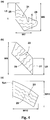
- FIG. 4(a) shows an enlarged view of the crown block 21.
- the crown block 21 preferably has, for example, a crown circumferential edge 25 extending along the tire circumferential direction.
- a length L5 in the tire circumferential direction of the crown circumferential edge 25 is preferably, for example, 0.50 to 0.70 times of a maximum width W6, in the tire circumferential direction, of the crown block 21.
- Such a crown block 21 causes the crown circumferential edge 25 to exert frictional force in the tire axial direction with moderate deformation thereof. Therefore, for example, the crown block 21 can exert frictional force in the tire axial direction, during running on a packed-snow road surface obtained by snow being packed, while inhibiting clogging of the main groove 11 with snow.
- a body width W7 of the crown block 21 from the tire equator C to the crown circumferential edge 25 is preferably, for example, 0.10 to 0.20 times of the tread width TW. Accordingly, a sufficient rubber volume is ensured between the crown circumferential edge 25 and the tire equator C.
- the crown circumferential edge 25 is relatively close to the tire equator C, and a large contact pressure acts on the crown circumferential edge 25.
- the crown circumferential edge 25 can provide large frictional force on a packed-snow road surface.
- a plurality of crown sipes 26 are preferably provided.
- Each crown sipe 26 of the present embodiment extends, for example, in a zigzagging manner in the tire axial direction.
- Such a crown sipe 26 allows the crown block 21 to moderately deform during running on snow and thus can further inhibit clogging of the slanted groove 10 and the main groove 11 with snow.
- the "sipe" means a slit having a width less than 2.0 mm.
- the middle block 22 is demarcated between the main groove 11 and the connection groove 18.
- the above-described lug groove 15 is provided in the middle block 22 .
- a maximum width W8, in the tire axial direction, of the middle block 22 is preferably, for example, 1.20 to 1.40 times of the body width W7 of the crown block 21.
- FIG. 4(b) shows an enlarged view of the middle block 22.
- the middle block 22 preferably has, for example, a middle circumferential edge 27 extending along the tire circumferential direction.
- a length L6, in the tire circumferential direction, of the middle circumferential edge 27 is preferably, for example, 0.55 to 0.70 times of a maximum width W9, in the tire circumferential direction, of the middle block 22.
- Such a middle block 22 causes the middle circumferential edge 27 to exert frictional force in the tire axial direction with moderate deformation thereof. Therefore, for example, the middle block 22 can exert frictional force in the tire axial direction, during running on a packed-snow road surface, while inhibiting clogging of the slanted groove 10 and the main groove 11 with snow.
- each middle sipe 28 is preferably slanted relative to the tire circumferential direction in the same direction as the lug groove 15 and extends in a zigzagging manner.
- Such a middle sipe 28, together with the lug groove 15, promotes deformation of the middle block 22 and thus can further inhibit clogging of the slanted groove 10 and the main groove 11 with snow.
- the shoulder block 23 is demarcated between the connection groove 18 and the first tread edge Te1.
- FIG. 4(c) shows an enlarged view of the shoulder block 23.
- a maximum width W10, in the tire axial direction, of the shoulder block 23 is preferably, for example, 1.45 to 1.65 times of the body width W7 of the crown block 21.
- a ratio W10/W11 of the maximum width W10, in the tire axial direction, to a maximum width W11, in the tire circumferential direction, of the shoulder block 23 is, for example, 0.90 to 1.10.
- Such a shoulder block 23 maintains the stiffness in the tire circumferential direction and in the tire axial direction in a balanced manner and thus can enhance the steering stability on a dry road surface.
- each shoulder sipe 29 is preferably slanted relative to the tire circumferential direction in a direction opposite to that of the connection groove 18 and extends in a zigzagging manner.
- FIG. 5 shows a plan view illustrating a ground-contact surface 2s of the tread portion 2.
- the ground-contact surface 2s is colored.
- the ground-contact surface 2s in FIG. 5 is a ground-contact surface when the tire 1 is mounted on a normal rim with the normal internal pressure and the normal load is applied to the tire 1 such that the tread portion 2 is brought into contact with a plane at a camber angle of 0°. As shown in FIG.
- a ratio W1/L1 of a maximum ground-contact width W1 in the tire axial direction to a ground-contact length L1 in the tire circumferential direction on the tire equator C is preferably not less than 1.10 and more preferably not less than 1.35 and is preferably not greater than 1.80 and more preferably not greater than 1.65. More specifically, the maximum ground-contact width W1 is preferably, for example, 200 to 250 mm.
- the present invention can inhibit a hydroplaning phenomenon, in such a tire having a relatively large ground-contact width W1, while maintaining the steering stability on a dry road surface and the performance on snow.
- a land ratio Lr of the tread portion 2 of the present embodiment is preferably not less than 60% and more preferably not less than 65% and is preferably not greater than 80% and more preferably not greater than 75%. Accordingly, the steering stability on a dry road surface and the performance on snow are enhanced in a balanced manner.
- the "land ratio" is a ratio Sb/Sa of an actual total contact area Sb to a whole area Sa of a virtual ground-contact surface obtained by filling each groove and each sipe.
- a rubber hardness Ht of a tread rubber forming the tread portion 2 is preferably not less than 45° and more preferably not less than 55° and is preferably not greater than 70° and more preferably not greater than 65°.
- the "rubber hardness” is a hardness measured with a type A durometer in the environment at 23°C according to JIS-K6253.
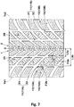
- FIGS. 6 and 7 each show a development of a tread portion 2 of a pneumatic tire 1 according to another embodiment of the present invention.
- the elements common to the above embodiment are designated by the same reference characters, and the description thereof is omitted here.
- main grooves 11 are provided outward of those of the above-described embodiment in the tire axial direction.
- the distance L3 in the tire axial direction from the tire equator C to each main groove 11 is 0.25 to 0.35 times of the tread width TW.
- Such a main groove 11 enhances the stiffness near the tire equator C and thus can achieve excellent steering stability on a dry road surface, as compared to that of the embodiment shown in FIG. 1 .
- the above-described lug grooves 15 are provided between each main groove 11 and the tire equator C.
- the above-described connection grooves 18 are provided between each lug groove 15 and the tire equator C. Accordingly, a decrease in drainage performance due to the increase in the distance L3 is prevented, and thus a hydroplaning phenomenon can be inhibited.
- a plurality of main grooves 11 are provided between the tire equator C and the first tread edge Te1.
- an inner main groove 31 is provided closest to the tire equator C
- an outer main groove 32 is provided between the inner main groove 31 and the first tread edge Te1.
- a distance L3a in the tire axial direction from the tire equator C to the groove center line of the inner main groove 31 is preferably, for example, 0.10 to 0.20 times of the tread width TW.
- a distance L3b in the tire axial direction from the tire equator C to the groove center line of the outer main groove 32 is preferably, for example, 0.25 to 0.35 times of the tread width TW.
- An intersection angle ⁇ 2a between the groove center line of the inner main groove 31 and the groove center line of each slanted groove 10 is preferably, for example, 35 to 45°.
- An intersection angle ⁇ 2b between the groove center line of the outer main groove 32 and the groove center line of each slanted groove 10 is preferably, for example, 40 to 50°. Accordingly, the respective main grooves 31 and 32 and the slanted grooves 10 can cooperate to inhibit a hydroplaning phenomenon.
- lug grooves 15 are provided between the inner main groove 31 and the outer main groove 32 so as to be adjacent thereto. Accordingly, each middle block 22 between the inner main groove 31 and the outer main groove 32 easily deforms moderately, and thus clogging of the inner main groove 31 and the outer main groove 32 with snow is inhibited during running on snow.
- Pneumatic tires with a size of 255/55R18 having the basic tread pattern in FIG. 1 were produced as samples on the basis of specifications in Table 1.
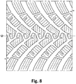
- Tires having no main groove extending continuously in the tire circumferential direction as shown in FIG. 8 were produced as samples of a comparative example.
- Each test tire was tested for steering stability on a dry road surface, wet performance, and performance on snow.
- the common specifications and the test methods for each test tire are as follows.
Landscapes
- Engineering & Computer Science (AREA)
- Mechanical Engineering (AREA)
- Tires In General (AREA)
Abstract
Description
- The present invention relates to a pneumatic tire that can effectively inhibit a hydroplaning phenomenon while maintaining steering stability on a dry road surface and performance on snow.
- For example, Japanese Laid-Open Patent Publication No.
2016-196288 2016-196288 - Meanwhile, recent tires have had widened treads, that is, increased tread widths, for enhancing running performance. However, when a tread pattern having no main groove as in Japanese Laid-Open Patent Publication No.
2016-196288 - The present invention has been made in view of the above-described problem, and a main object of the present invention is to provide a pneumatic tire that can inhibit a hydroplaning phenomenon while maintaining steering stability on a dry road surface and performance on snow.
- The present invention is directed to a pneumatic tire having a tread portion, wherein: in the tread portion, a main groove is provided so as to extend continuously in a tire circumferential direction between a tire equator and a first tread edge at one side in a tire axial direction, a plurality of slanted grooves are each provided so as to extend obliquely from the first tread edge toward the tire equator side and terminate at a position at the tire equator side beyond the main groove, and a plurality of slanted land portions are each provided so as to be demarcated between the slanted grooves adjacent to each other in the tire circumferential direction; and in at least one of the slanted land portions, a lug groove that is connected at one end thereof to the slanted groove and that terminates at another end thereof within the slanted land portion is provided so as to be adjacent to the main groove.
- In the pneumatic tire according to the present invention, the lug groove is preferably provided at the first tread edge side of the main groove.
- In the pneumatic tire according to the present invention, the lug groove is preferably slanted in a direction away from the main groove while extending from the one end toward the other end thereof.
- In the pneumatic tire according to the present invention, the slanted groove preferably has a larger groove width than the main groove.
- In the pneumatic tire according to the present invention, a distance in the tire axial direction from the tire equator to a groove center line of the main groove is preferably 0.10 to 0.20 times of a tread width.
- In the pneumatic tire according to the present invention, a ratio W1/L1 of a maximum ground-contact width W1 in the tire axial direction relative to a ground-contact length L1 in the tire circumferential direction on the tire equator C in a ground-contact surface of the tread portion when the pneumatic tire is mounted on a normal rim with a normal internal pressure and a normal load is applied to the pneumatic tire such that the tread portion is brought into contact with a plane at a camber angle of 0°, is preferably 1.10 to 1.80.
- In the pneumatic tire according to the present invention, the maximum ground-contact width W1 is preferably 200 to 250 mm.
- In the tread portion of the pneumatic tire according to the present invention, the main groove is provided so as to extend continuously in the tire circumferential direction between the tire equator and the first tread edge at the one side in the tire axial direction, the plurality of slanted grooves are each provided so as to extend obliquely from the first tread edge toward the tire equator side and terminate at a position at the tire equator side beyond the main groove, and the plurality of slanted land portions are each provided so as to be demarcated between the slanted grooves adjacent to each other in the tire circumferential direction.
- The main groove achieves excellent drainage performance and thus effectively inhibits a hydroplaning phenomenon. In addition, during running on snow, each slanted groove forms a long snow column extending obliquely relative to the tire axial direction and shears the snow column, whereby great on-snow traction can be obtained.
- In at least one of the slanted land portions, the lug groove that is connected at one end thereof to the slanted groove and that terminates at another end thereof within the slanted land portion is provided so as to be adjacent to the main groove. Such a lug groove can enhance wet performance and performance on snow while maintaining steering stability on a dry road surface by inhibiting a decrease in the stiffness of the slanted land portion. In addition, the lug groove adjacent to the main groove allows the slanted land portion to moderately deform, thereby inhibiting clogging of the main groove and the slanted groove with snow during running on snow, whereby excellent performance on snow can be continuously exerted.
- As described above, the pneumatic tire according to the present invention can inhibit a hydroplaning phenomenon while maintaining steering stability on a dry road surface and performance on snow.
-
-
FIG. 1 is a development of a tread portion of a pneumatic tire according to an embodiment of the present invention; -
FIG. 2 is an enlarged view of a first tread portion inFIG. 1 ; -
FIG. 3 is an enlarged view of a slanted land portion inFIG. 2 ; -
FIG. 4(a) is an enlarged view of a crown block inFIG. 3 ; -
FIG. 4(b) is an enlarged view of a middle block inFIG. 3 ; -
FIG. 4(c) is an enlarged view of a shoulder block inFIG. 3 ; -
FIG. 5 is a plan view of a ground-contact surface of the tread portion; -
FIG. 6 is a development of a tread portion of a pneumatic tire according to another embodiment of the present invention; -
FIG. 7 is a development of a tread portion of a pneumatic tire according to still another embodiment of the present invention; and -
FIG. 8 is a development of a tread portion of a pneumatic tire of a comparative example. - Hereinafter, an embodiment of the present invention will be described with reference to the drawings.
-
FIG. 1 is a development of atread portion 2 of a pneumatic tire (hereinafter, referred to merely as "tire") 1 according to the present embodiment. As shown inFIG. 1 , the tire 1 according to the present embodiment is suitably used, for example, as a winter pneumatic tire for a passenger car. In another embodiment of the present invention, the tire 1 can be used, for example, as a heavy duty pneumatic tire. - The tire 1 according to the present embodiment has a directional pattern for which a rotation direction R is designated. The rotation direction R is shown, for example, on each side wall (not shown) by a character or a symbol.
- The tire 1 according to the present embodiment has the
tread portion 2 between a first tread edge Te1 and a second tread edge Te2. Thetread portion 2 includes afirst tread portion 2A between a tire equator C and the first tread edge Te1, and asecond tread portion 2B between the tire equator C and the second tread edge Te2. - In the case of a pneumatic tire, each of the first tread edge Te1 and the second tread edge Te2 is a ground contact position at the outermost side in the tire axial direction when a normal load is applied to the tire 1 in a normal state and the tire 1 is brought into contact with a plane at a camber angle of 0°. The normal state is a state where the tire is mounted to a normal rim and inflated to a normal internal pressure and no load is applied to the tire. In the present specification, unless otherwise specified, dimensions of components of the tire and the like are values measured in the normal state.
- The "normal rim" is a rim that is defined, in a standard system including a standard on which the tire is based, by the standard for each tire, and is, for example, the "standard rim" in the JATMA standard, the "Design Rim" in the TRA standard, or the "Measuring Rim" in the ETRTO standard.
- The "normal internal pressure" is an air pressure that is defined, in a standard system including a standard on which the tire is based, by the standard for each tire, and is the "maximum air pressure" in the JATMA standard, the maximum value indicated in the table "TIRE LOAD LIMITS AT VARIOUS COLD INFLATION PRESSURES" in the TRA standard, or the "INFLATION PRESSURE" in the ETRTO standard.
- The "normal load" is a load that is defined, in a standard system including a standard on which the tire is based, by the standard for each tire, and is the "maximum load capacity" in the JATMA standard, the maximum value indicated in the table "TIRE LOAD LIMITS AT VARIOUS COLD INFLATION PRESSURES" in the TRA standard, or the "LOAD CAPACITY" in the ETRTO standard.
- In the
tread portion 2, amain groove 11 is provided in each of thetread portions slanted grooves 10 are provided. Themain groove 11 achieves excellent drainage performance and thus can effectively inhibit a hydroplaning phenomenon. - The
slanted grooves 10 include, for example, firstslanted grooves 10A provided in thefirst tread portion 2A, and secondslanted grooves 10B provided in thesecond tread portion 2B. Thefirst slanted grooves 10A extend obliquely from the first tread edge Te1 toward the tire equator C side. Thesecond slanted grooves 10B extend obliquely from the second tread edge Te2 toward the tire equator C side. The secondslanted grooves 10B have substantially the same configuration as thefirst slanted grooves 10A. Thus, unless mentioned otherwise, the configurations of the firstslanted grooves 10A can be applied to the secondslanted grooves 10B. During running on snow, eachslanted groove 10 forms a long snow column extending obliquely relative to the tire axial direction and shears the snow column, whereby great on-snow traction can be obtained. - In a preferable mode, each of the
slanted grooves -
FIG. 2 shows an enlarged view of thefirst tread portion 2A. As shown inFIG. 2 , for example, eachslanted groove 10 is preferably curved such that an angle θ1 of theslanted groove 10 relative to the tire axial direction gradually increases toward the tire equator C side. The angle θ1 is preferably, for example, 25 to 80°. Such aslanted groove 10 can exert great snow column shearing force also in the tire axial direction during running on snow. - The
slanted groove 10 terminates at a position at the tire equator C side beyond themain groove 11. For example, the slantedgroove 10 terminates without traversing the tire equator C. A distance L2 in the tire axial direction from an inner end (which means the inner end, in the tire axial direction, of a groove center line, the same applies to the following) of the slantedgroove 10 to the tire equator C is preferably, for example, 2.0% to 5.0% of a tread width TW (shown inFIG. 1 , the same applies to the following). The tread width TW is the distance in the tire axial direction from the first tread edge Te1 to the second tread edge Te2 in the normal state. - The slanted
groove 10 preferably has, for example, a groove width that gradually increases toward the first tread edge Te1 side. At least a portion of the slantedgroove 10 preferably has, for example, a larger groove width than themain groove 11. A maximum groove width W2 of the slantedgroove 10 is preferably, for example, 5.0% to 9.0% of the tread width TW. In the case of a winter tire for a passenger car, the depth of the slantedgroove 10 is preferably, for example, 7.0 to 11.0 mm. - As shown in
FIG. 1 , themain grooves 11 include, for example, a firstmain groove 11 A provided in thefirst tread portion 2A, and a secondmain groove 11B provided in thesecond tread portion 2B. In the present embodiment, onemain groove 11 is provided in each of thetread portions main groove 11B has substantially the same configuration as the firstmain groove 11A. Thus, unless mentioned otherwise, the configuration of the firstmain groove 11A can be applied to the secondmain groove 11B. - As shown in
FIG. 2 , eachmain groove 11 of the present embodiment is configured such that, for example, a plurality ofgroove portions 11a each connecting theslanted grooves 10 adjacent to each other in the tire circumferential direction are aligned in the tire circumferential direction, whereby theadjacent groove portions 11a are continuous. More specifically, eachgroove portion 11a is at least connected to thegroove portion 11a adjacent thereto in the tire circumferential direction when being virtually extended in the tire circumferential direction. In a preferable mode, when eachgroove portion 11 a is virtually extended, thegroove portion 11a overlaps thegroove portion 11a adjacent thereto in the tire circumferential direction, and such an overlap is over half or more of the groove width thereof. As a more preferable mode, in the present embodiment, the groove edges, at each side, of therespective groove portions 11a are provided on the same straight line. Accordingly, eachmain groove 11 of the present embodiment extends so as to be continuous in a straight manner along the tire circumferential direction. - A distance L3 in the tire axial direction from the tire equator C to the groove center line of the
main groove 11 is preferably 0.10 to 0.20 times of the tread width TW. Such amain groove 11 can effectively enhance the drainage performance near the tire equator C. - An intersection angle θ2 between the groove center line of the
main groove 11 and the groove center line of the slantedgroove 10 is preferably not less than 30° and more preferably not less than 35°, and is preferably not greater than 50° and more preferably not greater than 45°. When the slantedgroove 10 is slanted in the above-described direction, and the intersection angle θ2 falls within the above range, part of water within themain groove 11 is easily drained through the slantedgroove 10 to the outer side in the tire axial direction during wet running. Thus, even with themain groove 11 having a relatively small groove width and groove depth, desired drainage performance is achieved. Therefore, the steering stability on a dry road surface and the wet performance can be enhanced in a balanced manner. - In order to enhance the steering stability on a dry road surface and the wet performance in a balanced manner, the
main groove 11 preferably has, for example, a groove width W3 that is 2.5% to 3.5% of the tread width TW. Themain groove 11 preferably has, for example, a smaller groove depth in thegroove portion 11a than the slantedgroove 10. In the case of a winter tire for a passenger car, the groove depth is preferably, for example, 5.0 to 10.0 mm. - In the
tread portion 2 of the present embodiment, for example, centralaxial grooves 12 are preferably provided. For example, each centralaxial groove 12 branches from the slantedgroove 10 and extends in the tire axial direction so as to traverse the tire equator C. More specifically, the centralaxial grooves 12 include first centralaxial grooves 12A and second centralaxial grooves 12B. The first centralaxial grooves 12A are slanted in the same direction as the firstslanted grooves 10A. Each first centralaxial groove 12A branches from the firstslanted groove 10A, extends in the tire axial direction, and is connected to the secondslanted groove 10B. The second centralaxial grooves 12B are slanted in the same direction as the second slantedgrooves 10B. Each second centralaxial groove 12B branches from the secondslanted groove 10B, extends in the tire axial direction, and is connected to the firstslanted groove 10A. The first centralaxial grooves 12A and the second centralaxial grooves 12B are alternately provided in the tire circumferential direction. - Each central
axial groove 12 is preferably provided, for example, at an angle θ3 of 15 to 30°relative to the tire axial direction. - In the
tread portion 2, slantedland portions 13 are provided. Each slantedland portion 13 is demarcated between theslanted grooves 10 adjacent to each other in the tire circumferential direction. Each slantedland portion 13 of the present embodiment includes, for example, a region demarcated between the first centralaxial groove 12A and the second centralaxial groove 12B. - As shown in
FIG. 1 , the slantedland portions 13 include, for example, first slantedland portions 13A demarcated between a plurality of the firstslanted grooves 10A, and second slantedland portions 13B demarcated between a plurality of the second slantedgrooves 10B. The second slantedland portions 13B have substantially the same configuration as the first slantedland portions 13A. Thus, unless mentioned otherwise, the configurations of the first slantedland portions 13A can be applied to the second slantedland portions 13B. - As shown in
FIG. 2 , alug groove 15 is provided in at least one of the slantedland portions 13 so as to be adjacent to themain groove 11. Thelug groove 15 is connected at oneend 15a thereof to the slantedgroove 10 and terminates at anotherend 15b thereof within the slantedland portion 13. Such alug groove 15 can enhance the wet performance and the performance on snow while maintaining the steering stability on a dry road surface by inhibiting a decrease in the stiffness of the slantedland portion 13. In addition, thelug groove 15 adjacent to themain groove 11 allows the slantedland portion 13 to moderately deform, thereby inhibiting clogging of themain groove 11 and the slantedgroove 10 with snow during running on snow, whereby excellent performance on snow can be continuously exerted. - The
lug groove 15 of the present embodiment is preferably provided at the first tread edge Te1 side of themain groove 11. In addition, thelug groove 15 is preferably connected to the slantedgroove 10 at the forward side in the rotation direction R. - The
lug groove 15 is preferably slanted in a direction away from themain groove 11 while extending from the oneend 15a to theother end 15b. For example, thelug groove 15 of the present embodiment is slanted at an angle θ4 of 45 to 65°relative to the tire circumferential direction. Such alug groove 15 serves to deform the slantedland portion 13 in the tire axial direction and in the tire circumferential direction and can further inhibit clogging with snow. - At the one
end 15a side of thelug groove 15, the point of intersection between an extension of the groove center line of thelug groove 15 and the groove center line of the slantedgroove 10 is defined as a first point ofintersection 16. A distance L4 in the tire axial direction from the tire equator C to the first point ofintersection 16 is preferably, for example, 1.30 to 1.50 times of the distance L3 in the tire axial direction from the tire equator C to the groove center line of themain groove 11. Such alug groove 15 can inhibit clogging of themain groove 11 with snow during running on snow while appropriately maintaining the stiffness of the slantedland portion 13. - The
lug groove 15 preferably has, for example, a groove width W4 smaller than the groove width W3 of themain groove 11. The groove width W4 of thelug groove 15 is preferably, for example, 0.50 to 0.70 times of the groove width W3 of themain groove 11. Such alug groove 15 can enhance the steering stability on a dry road surface and the performance on snow in a balanced manner. - For example, the
lug groove 15 has a smaller depth than the slantedgroove 10. In a more preferable mode, thelug groove 15 has a smaller depth than themain groove 11. Accordingly, the stiffness of the slantedland portion 13 is enhanced, and thus the steering stability on a dry road surface is enhanced. - In each
slanted land portion 13, aconnection groove 18 is preferably further provided so as to connect between theslanted grooves 10 adjacent to each other in the tire circumferential direction. Theconnection groove 18 of the present embodiment is provided, for example, between thelug groove 15 and the first tread edge Te1. - The
connection groove 18 is preferably slanted, for example, relative to the tire circumferential direction in the same direction as thelug groove 15. Theconnection groove 18 of the present embodiment is slanted, for example, at a smaller angle θ5 relative to the tire circumferential direction than thelug groove 15. The angle θ5 of theconnection groove 18 is preferably, for example, 15 to 30°. Such aconnection groove 18, together with thelug groove 15, further promotes deformation of the slantedland portion 13 and thus can further inhibit clogging of the slantedgroove 10 and themain groove 11 with snow. - The
connection groove 18 preferably has, for example, a smaller depth than the slantedgroove 10. In a more preferable mode, theconnection groove 18 has a smaller depth than themain groove 11. Accordingly, the stiffness of the slantedland portion 13 is enhanced, and thus the steering stability on a dry road surface is enhanced. - In order to enhance the steering stability on a dry road surface and the wet performance in a balanced manner, the
connection groove 18 preferably has, for example, a smaller groove width W5 than themain groove 11. The groove width W5 of theconnection groove 18 is preferably, for example, 0.50 to 0.70 times of the groove width W3 of themain groove 11. -
FIG. 3 shows an enlarged view of the slantedland portion 13. As shown inFIG. 3 , for example, , the slantedland portion 13 is demarcated by the above-described grooves so as to include acrown block 21, amiddle block 22, and ashoulder block 23. - For example, the
crown block 21 is demarcated at the inner side, in the tire axial direction, of themain groove 11. Thecrown block 21 includes, for example, a region demarcated between theslanted grooves 10 adjacent to each other in the tire circumferential direction, and a region demarcated between the first centralaxial groove 12A and the second centralaxial groove 12B. -
FIG. 4(a) shows an enlarged view of thecrown block 21. As shown inFIG. 4(a) , thecrown block 21 preferably has, for example, acrown circumferential edge 25 extending along the tire circumferential direction. A length L5 in the tire circumferential direction of thecrown circumferential edge 25 is preferably, for example, 0.50 to 0.70 times of a maximum width W6, in the tire circumferential direction, of thecrown block 21. Such acrown block 21 causes thecrown circumferential edge 25 to exert frictional force in the tire axial direction with moderate deformation thereof. Therefore, for example, thecrown block 21 can exert frictional force in the tire axial direction, during running on a packed-snow road surface obtained by snow being packed, while inhibiting clogging of themain groove 11 with snow. - A body width W7 of the
crown block 21 from the tire equator C to thecrown circumferential edge 25 is preferably, for example, 0.10 to 0.20 times of the tread width TW. Accordingly, a sufficient rubber volume is ensured between thecrown circumferential edge 25 and the tire equator C. In addition, thecrown circumferential edge 25 is relatively close to the tire equator C, and a large contact pressure acts on thecrown circumferential edge 25. Thus, for example, thecrown circumferential edge 25 can provide large frictional force on a packed-snow road surface. - In the
crown block 21, for example, a plurality ofcrown sipes 26 are preferably provided. Eachcrown sipe 26 of the present embodiment extends, for example, in a zigzagging manner in the tire axial direction. Such acrown sipe 26 allows thecrown block 21 to moderately deform during running on snow and thus can further inhibit clogging of the slantedgroove 10 and themain groove 11 with snow. In the present specification, the "sipe" means a slit having a width less than 2.0 mm. - As shown in
FIG. 3 , for example, themiddle block 22 is demarcated between themain groove 11 and theconnection groove 18. In themiddle block 22, the above-describedlug groove 15 is provided. A maximum width W8, in the tire axial direction, of themiddle block 22 is preferably, for example, 1.20 to 1.40 times of the body width W7 of thecrown block 21. -
FIG. 4(b) shows an enlarged view of themiddle block 22. As shown inFIG. 4(b) , themiddle block 22 preferably has, for example, a middlecircumferential edge 27 extending along the tire circumferential direction. A length L6, in the tire circumferential direction, of the middlecircumferential edge 27 is preferably, for example, 0.55 to 0.70 times of a maximum width W9, in the tire circumferential direction, of themiddle block 22. Such amiddle block 22 causes the middlecircumferential edge 27 to exert frictional force in the tire axial direction with moderate deformation thereof. Therefore, for example, themiddle block 22 can exert frictional force in the tire axial direction, during running on a packed-snow road surface, while inhibiting clogging of the slantedgroove 10 and themain groove 11 with snow. - In the
middle block 22, for example, a plurality ofmiddle sipes 28 are preferably provided. For example, eachmiddle sipe 28 is preferably slanted relative to the tire circumferential direction in the same direction as thelug groove 15 and extends in a zigzagging manner. Such amiddle sipe 28, together with thelug groove 15, promotes deformation of themiddle block 22 and thus can further inhibit clogging of the slantedgroove 10 and themain groove 11 with snow. - As shown in
FIG. 3 , for example, theshoulder block 23 is demarcated between theconnection groove 18 and the first tread edge Te1. -
FIG. 4(c) shows an enlarged view of theshoulder block 23. As shown inFIG. 4(c) , a maximum width W10, in the tire axial direction, of theshoulder block 23 is preferably, for example, 1.45 to 1.65 times of the body width W7 of thecrown block 21. - In a preferable mode, a ratio W10/W11 of the maximum width W10, in the tire axial direction, to a maximum width W11, in the tire circumferential direction, of the
shoulder block 23 is, for example, 0.90 to 1.10. Such ashoulder block 23 maintains the stiffness in the tire circumferential direction and in the tire axial direction in a balanced manner and thus can enhance the steering stability on a dry road surface. - In the
shoulder block 23, for example, a plurality ofshoulder sipes 29 are preferably provided. For example, eachshoulder sipe 29 is preferably slanted relative to the tire circumferential direction in a direction opposite to that of theconnection groove 18 and extends in a zigzagging manner. -
FIG. 5 shows a plan view illustrating a ground-contact surface 2s of thetread portion 2. InFIG. 5 , the ground-contact surface 2s is colored. The ground-contact surface 2s inFIG. 5 is a ground-contact surface when the tire 1 is mounted on a normal rim with the normal internal pressure and the normal load is applied to the tire 1 such that thetread portion 2 is brought into contact with a plane at a camber angle of 0°. As shown inFIG. 5 , in the ground-contact surface 2s, a ratio W1/L1 of a maximum ground-contact width W1 in the tire axial direction to a ground-contact length L1 in the tire circumferential direction on the tire equator C is preferably not less than 1.10 and more preferably not less than 1.35 and is preferably not greater than 1.80 and more preferably not greater than 1.65. More specifically, the maximum ground-contact width W1 is preferably, for example, 200 to 250 mm. The present invention can inhibit a hydroplaning phenomenon, in such a tire having a relatively large ground-contact width W1, while maintaining the steering stability on a dry road surface and the performance on snow. - As shown in
FIG. 1 , a land ratio Lr of thetread portion 2 of the present embodiment is preferably not less than 60% and more preferably not less than 65% and is preferably not greater than 80% and more preferably not greater than 75%. Accordingly, the steering stability on a dry road surface and the performance on snow are enhanced in a balanced manner. In the present specification, the "land ratio" is a ratio Sb/Sa of an actual total contact area Sb to a whole area Sa of a virtual ground-contact surface obtained by filling each groove and each sipe. - From the same viewpoint, a rubber hardness Ht of a tread rubber forming the
tread portion 2 is preferably not less than 45° and more preferably not less than 55° and is preferably not greater than 70° and more preferably not greater than 65°. In the present specification, the "rubber hardness" is a hardness measured with a type A durometer in the environment at 23°C according to JIS-K6253. -
FIGS. 6 and7 each show a development of atread portion 2 of a pneumatic tire 1 according to another embodiment of the present invention. InFIGS. 6 and7 , the elements common to the above embodiment are designated by the same reference characters, and the description thereof is omitted here. - In the embodiment shown in
FIG. 6 ,main grooves 11 are provided outward of those of the above-described embodiment in the tire axial direction. In this embodiment, the distance L3 in the tire axial direction from the tire equator C to eachmain groove 11 is 0.25 to 0.35 times of the tread width TW. Such amain groove 11 enhances the stiffness near the tire equator C and thus can achieve excellent steering stability on a dry road surface, as compared to that of the embodiment shown inFIG. 1 . - In this embodiment, the above-described
lug grooves 15 are provided between eachmain groove 11 and the tire equator C. In addition, the above-describedconnection grooves 18 are provided between eachlug groove 15 and the tire equator C. Accordingly, a decrease in drainage performance due to the increase in the distance L3 is prevented, and thus a hydroplaning phenomenon can be inhibited. - In the embodiment shown in
FIG. 7 , a plurality ofmain grooves 11 are provided between the tire equator C and the first tread edge Te1. In thetread portion 2 of this embodiment, for example, an innermain groove 31 is provided closest to the tire equator C, and an outermain groove 32 is provided between the innermain groove 31 and the first tread edge Te1. In such an embodiment, further excellent drainage performance can be achieved. - A distance L3a in the tire axial direction from the tire equator C to the groove center line of the inner
main groove 31 is preferably, for example, 0.10 to 0.20 times of the tread width TW. A distance L3b in the tire axial direction from the tire equator C to the groove center line of the outermain groove 32 is preferably, for example, 0.25 to 0.35 times of the tread width TW. - An intersection angle θ2a between the groove center line of the inner
main groove 31 and the groove center line of each slantedgroove 10 is preferably, for example, 35 to 45°. An intersection angle θ2b between the groove center line of the outermain groove 32 and the groove center line of each slantedgroove 10 is preferably, for example, 40 to 50°. Accordingly, the respectivemain grooves slanted grooves 10 can cooperate to inhibit a hydroplaning phenomenon. - In this embodiment, lug
grooves 15 are provided between the innermain groove 31 and the outermain groove 32 so as to be adjacent thereto. Accordingly, eachmiddle block 22 between the innermain groove 31 and the outermain groove 32 easily deforms moderately, and thus clogging of the innermain groove 31 and the outermain groove 32 with snow is inhibited during running on snow. - Although the pneumatic tire according to the embodiment of the present invention has been described in detail above, the present invention is not limited to the above specific embodiments, and various modifications can be made to implement the present invention.
- Pneumatic tires with a size of 255/55R18 having the basic tread pattern in
FIG. 1 were produced as samples on the basis of specifications in Table 1. Tires having no main groove extending continuously in the tire circumferential direction as shown inFIG. 8 were produced as samples of a comparative example. Each test tire was tested for steering stability on a dry road surface, wet performance, and performance on snow. The common specifications and the test methods for each test tire are as follows. - Test vehicle: a four-wheel-drive vehicle having a displacement of 3600 cc
- Test tire mounted position: all wheels
- Rim: 18×8.0
- Tire internal pressure: front wheel 230 kPa, rear wheel 250 kPa
- Tread ground-contact width: 224 mm
- Groove depth of slanted groove: 8.6 mm
- Ground-contact width W1/ground-contact length L1: 1.46
- Land ratio: 67%
- Rubber hardness Ht of tread rubber: 65
- Sensory evaluation was made by a driver for steering stability when the driver drove the above test vehicle on a circuit track having a dry road surface. The results are scores obtained on the basis of the result of the comparative example being 100. A higher value indicates that the steering stability on the dry road surface is better.
- Using an inside drum tester, the speed of occurrence of a hydroplaning phenomenon was measured when each test tire ran on a drum surface at a water depth of 5.0 mm under the following conditions. The results are indexes obtained on the basis of the result of the comparative example being 100. A higher value indicates that the speed of occurrence is higher and the wet performance is better.
- Slip angle: 1.0°
- Vertical load: 4.2 kN
- Sensory evaluation was made by a driver for running performance when the driver drove the above test vehicle on a snowy road surface. The results are scores obtained on the basis of the result of the comparative example being 100. A higher value indicates that the performance on snow is better.
- The test results are shown in Table 1.
[Table 1] Comparative Example 1 Example 1 Example 2 Example 3 Example 4 Example 5 Figure showing tread pattern FIG. 8 FIG. 1 FIG. 1 FIG. 1 FIG. 6 FIG. 7 Distance L3 from tire equator to main groove/tread width TW - 0.15 0.10 0.20 0.30 L3a: 0.15 L3b: 0.30 Groove width W3 of main groove/tread width TW (%) - 3.0 3.0 3.0 3.0 3.0 Intersection angle θ2 between main groove and slanted groove - 40 40 40 45 θ2a: 40 θ2b: 45 Steering stability on dry road surface (score) 100 102 100 102 104 96 Wet performance (index) 100 107 108 105 103 112 Performance on snow (score) 100 101 100 102 101 105 - As a result of the tests, it was confirmed that the pneumatic tires of the examples inhibit a hydroplaning phenomenon while maintaining the steering stability on a dry road surface and the performance on snow.
Claims (7)
- A pneumatic tire (1) having a tread portion (2), wherein
in the tread portion (2), a main groove (11) is provided so as to extend continuously in a tire circumferential direction between a tire equator (C) and a first tread edge (Te1) at one side in a tire axial direction, a plurality of slanted grooves (10) are each provided so as to extend obliquely from the first tread edge (Te1) toward the tire equator (C) side and terminate at a position at the tire equator (C) side beyond the main groove (11), and a plurality of slanted land portions (13) are each provided so as to be demarcated between the slanted grooves (10) adjacent to each other in the tire circumferential direction, and
in at least one of the slanted land portions (13), a lug groove (15) that is connected at one end thereof to the slanted groove (10) and that terminates at another end thereof within the slanted land portion (13) is provided so as to be adjacent to the main groove (11). - The pneumatic tire (1) according to claim 1, wherein the lug groove (15) is provided at the first tread edge (Te1) side of the main groove (11).
- The pneumatic tire (1) according to claim 1 or 2, wherein the lug groove (15) is slanted in a direction away from the main groove (11) while extending from the one end toward the other end thereof.
- The pneumatic tire (1) according to any one of claims 1 to 3, wherein each slanted groove (10) has a larger groove width than the main groove (11).
- The pneumatic tire (1) according to any one of claims 1 to 4, wherein a distance (L3) in the tire axial direction from the tire equator (C) to a groove center line of the main groove (11) is 0.10 to 0.20 times of a tread width (TW).
- The pneumatic tire (1) according to any one of claims 1 to 5, wherein a ratio W1/L1 of a maximum ground-contact width W1 in the tire axial direction to a ground-contact length L1 in the tire circumferential direction on the tire equator (C) in a ground-contact surface of the tread portion (2) when the pneumatic tire (1) is mounted on a normal rim with a normal internal pressure and a normal load is applied to the pneumatic tire (1) such that the tread portion (2) is brought into contact with a plane at a camber angle of 0°, is 1.10 to 1.80.
- The pneumatic tire (1) according to any one of claims 1 to 6, wherein the maximum ground-contact width W1 is 200 to 250 mm.
Applications Claiming Priority (1)
| Application Number | Priority Date | Filing Date | Title |
|---|---|---|---|
| JP2017077630A JP6885170B2 (en) | 2017-04-10 | 2017-04-10 | Pneumatic tires |
Publications (2)
| Publication Number | Publication Date |
|---|---|
| EP3388255A1 true EP3388255A1 (en) | 2018-10-17 |
| EP3388255B1 EP3388255B1 (en) | 2020-06-24 |
Family
ID=61007555
Family Applications (1)
| Application Number | Title | Priority Date | Filing Date |
|---|---|---|---|
| EP18152439.8A Active EP3388255B1 (en) | 2017-04-10 | 2018-01-19 | Pneumatic tire |
Country Status (3)
| Country | Link |
|---|---|
| EP (1) | EP3388255B1 (en) |
| JP (1) | JP6885170B2 (en) |
| CN (1) | CN108688411B (en) |
Cited By (1)
| Publication number | Priority date | Publication date | Assignee | Title |
|---|---|---|---|---|
| EP4592097A4 (en) * | 2022-11-04 | 2025-12-31 | Bridgestone Corp | TIRES |
Families Citing this family (9)
| Publication number | Priority date | Publication date | Assignee | Title |
|---|---|---|---|---|
| JP7159968B2 (en) * | 2019-04-26 | 2022-10-25 | 横浜ゴム株式会社 | pneumatic tire |
| JP7120146B2 (en) * | 2019-04-26 | 2022-08-17 | 横浜ゴム株式会社 | pneumatic tire |
| CN112622530B (en) * | 2019-10-08 | 2024-03-08 | 住友橡胶工业株式会社 | Tire with a tire body |
| JP7394613B2 (en) * | 2019-12-13 | 2023-12-08 | Toyo Tire株式会社 | pneumatic tires |
| JP7464819B2 (en) * | 2020-02-12 | 2024-04-10 | 横浜ゴム株式会社 | Pneumatic tires |
| JP7677826B2 (en) * | 2021-05-18 | 2025-05-15 | 株式会社ブリヂストン | Pneumatic tires |
| EP4137332B1 (en) * | 2021-08-19 | 2024-01-17 | Nokian Renkaat Oyj | A tread block arrangement for a tire or for a tread band |
| JP1717184S (en) | 2021-08-19 | 2022-06-13 | tire | |
| JP2025160687A (en) * | 2024-04-10 | 2025-10-23 | 横浜ゴム株式会社 | tire |
Citations (5)
| Publication number | Priority date | Publication date | Assignee | Title |
|---|---|---|---|---|
| EP2514608A2 (en) * | 2011-04-20 | 2012-10-24 | Sumitomo Rubber Industries Limited | Pneumatic tire |
| EP2522531A1 (en) * | 2011-05-12 | 2012-11-14 | Sumitomo Rubber Industries Limited | Pneumatic tire |
| EP2586628A2 (en) * | 2011-10-27 | 2013-05-01 | Sumitomo Rubber Industries, Ltd. | Pneumatic tire |
| JP2016196288A (en) | 2015-04-03 | 2016-11-24 | 住友ゴム工業株式会社 | Pneumatic tire |
| EP3290233A1 (en) * | 2016-08-23 | 2018-03-07 | Sumitomo Rubber Industries, Ltd. | Tire |
Family Cites Families (24)
| Publication number | Priority date | Publication date | Assignee | Title |
|---|---|---|---|---|
| DE4108745A1 (en) * | 1991-03-18 | 1992-09-24 | Sp Reifenwerke Gmbh | TIRE |
| DE4425899A1 (en) * | 1994-07-22 | 1996-01-25 | Continental Ag | Tread with tread pattern with S-shaped cross grooves |
| IT1287154B1 (en) * | 1996-11-12 | 1998-08-04 | Pirelli | TIRE TREAD BAND, ESPECIALLY FOR OFF-ROAD VEHICLES |
| JP3365731B2 (en) * | 1997-11-18 | 2003-01-14 | 住友ゴム工業株式会社 | Pneumatic tire |
| EP1215055B1 (en) * | 2000-12-12 | 2006-04-05 | Continental Aktiengesellschaft | Vehicle tyre with thread having good grip on snow and ice |
| JP2002274126A (en) * | 2001-03-15 | 2002-09-25 | Bridgestone Corp | Pneumatic tire |
| JP4759044B2 (en) * | 2008-12-22 | 2011-08-31 | 住友ゴム工業株式会社 | Pneumatic tire |
| JP5115487B2 (en) * | 2009-01-27 | 2013-01-09 | 横浜ゴム株式会社 | Pneumatic tire |
| JP4367965B1 (en) * | 2009-03-16 | 2009-11-18 | 横浜ゴム株式会社 | Pneumatic tire |
| CN103221235B (en) * | 2010-10-05 | 2015-08-19 | 株式会社普利司通 | tire |
| WO2012127839A1 (en) * | 2011-03-23 | 2012-09-27 | 株式会社ブリヂストン | Pneumatic tire |
| US10137739B2 (en) * | 2011-03-28 | 2018-11-27 | Bridgestone Corporation | Pneumatic tire |
| JP5316591B2 (en) * | 2011-06-08 | 2013-10-16 | 横浜ゴム株式会社 | Pneumatic tire |
| JP5480927B2 (en) * | 2012-03-14 | 2014-04-23 | 住友ゴム工業株式会社 | Pneumatic tire |
| JP6438768B2 (en) * | 2012-11-30 | 2018-12-19 | 株式会社ブリヂストン | Pneumatic tire |
| JP5986542B2 (en) * | 2013-07-12 | 2016-09-06 | 住友ゴム工業株式会社 | Pneumatic tire |
| CN103507574A (en) * | 2013-09-29 | 2014-01-15 | 正新橡胶(中国)有限公司 | Pneumatic tyre |
| JP6248537B2 (en) * | 2013-10-24 | 2017-12-20 | 横浜ゴム株式会社 | Pneumatic tire |
| DE102013225302A1 (en) * | 2013-12-09 | 2015-06-11 | Continental Reifen Deutschland Gmbh | Vehicle tires |
| JP6364783B2 (en) * | 2014-01-21 | 2018-08-01 | 横浜ゴム株式会社 | Pneumatic tire |
| JP6097263B2 (en) * | 2014-09-25 | 2017-03-15 | 住友ゴム工業株式会社 | Pneumatic tire |
| JP6360459B2 (en) * | 2015-05-26 | 2018-07-18 | 住友ゴム工業株式会社 | Winter tires |
| CN107645993B (en) * | 2015-05-27 | 2020-04-24 | 倍耐力轮胎股份公司 | Tyre for vehicle wheels |
| JP6555040B2 (en) * | 2015-09-16 | 2019-08-07 | 住友ゴム工業株式会社 | tire |
-
2017
- 2017-04-10 JP JP2017077630A patent/JP6885170B2/en active Active
-
2018
- 2018-01-19 EP EP18152439.8A patent/EP3388255B1/en active Active
- 2018-03-02 CN CN201810174695.3A patent/CN108688411B/en active Active
Patent Citations (5)
| Publication number | Priority date | Publication date | Assignee | Title |
|---|---|---|---|---|
| EP2514608A2 (en) * | 2011-04-20 | 2012-10-24 | Sumitomo Rubber Industries Limited | Pneumatic tire |
| EP2522531A1 (en) * | 2011-05-12 | 2012-11-14 | Sumitomo Rubber Industries Limited | Pneumatic tire |
| EP2586628A2 (en) * | 2011-10-27 | 2013-05-01 | Sumitomo Rubber Industries, Ltd. | Pneumatic tire |
| JP2016196288A (en) | 2015-04-03 | 2016-11-24 | 住友ゴム工業株式会社 | Pneumatic tire |
| EP3290233A1 (en) * | 2016-08-23 | 2018-03-07 | Sumitomo Rubber Industries, Ltd. | Tire |
Cited By (1)
| Publication number | Priority date | Publication date | Assignee | Title |
|---|---|---|---|---|
| EP4592097A4 (en) * | 2022-11-04 | 2025-12-31 | Bridgestone Corp | TIRES |
Also Published As
| Publication number | Publication date |
|---|---|
| CN108688411B (en) | 2021-12-24 |
| EP3388255B1 (en) | 2020-06-24 |
| CN108688411A (en) | 2018-10-23 |
| JP2018176930A (en) | 2018-11-15 |
| JP6885170B2 (en) | 2021-06-09 |
Similar Documents
| Publication | Publication Date | Title |
|---|---|---|
| EP3388255B1 (en) | Pneumatic tire | |
| EP3296127B1 (en) | Pneumatic tire | |
| EP3260308B1 (en) | Tire | |
| EP3388257B1 (en) | Tire | |
| EP3081393B1 (en) | Pneumatic tire | |
| EP3000622B1 (en) | Pneumatic tire | |
| EP3263367B1 (en) | Pneumatic tire | |
| EP2752309B1 (en) | Pneumatic tire | |
| EP3326840A1 (en) | Tire | |
| EP3248810B1 (en) | Tire | |
| EP3290233B1 (en) | Tire | |
| EP3315326B1 (en) | Tire | |
| EP3078507B1 (en) | Pneumatic tire | |
| EP3398793B1 (en) | Tire | |
| EP3318421B1 (en) | Tire | |
| EP3375633B1 (en) | Tire | |
| EP3403852B1 (en) | Tire | |
| KR20170116947A (en) | Pneumatic tire | |
| EP3747672B1 (en) | Tire tread | |
| EP3388254B1 (en) | Tire | |
| EP4484179A1 (en) | Tire | |
| CN104512205A (en) | Pneumatic tire | |
| EP3549789B1 (en) | Tyre | |
| EP3381715B1 (en) | Tire | |
| EP3549793B1 (en) | Tyre |
Legal Events
| Date | Code | Title | Description |
|---|---|---|---|
| PUAI | Public reference made under article 153(3) epc to a published international application that has entered the european phase |
Free format text: ORIGINAL CODE: 0009012 |
|
| STAA | Information on the status of an ep patent application or granted ep patent |
Free format text: STATUS: THE APPLICATION HAS BEEN PUBLISHED |
|
| AK | Designated contracting states |
Kind code of ref document: A1 Designated state(s): AL AT BE BG CH CY CZ DE DK EE ES FI FR GB GR HR HU IE IS IT LI LT LU LV MC MK MT NL NO PL PT RO RS SE SI SK SM TR |
|
| AX | Request for extension of the european patent |
Extension state: BA ME |
|
| STAA | Information on the status of an ep patent application or granted ep patent |
Free format text: STATUS: REQUEST FOR EXAMINATION WAS MADE |
|
| 17P | Request for examination filed |
Effective date: 20181219 |
|
| RBV | Designated contracting states (corrected) |
Designated state(s): AL AT BE BG CH CY CZ DE DK EE ES FI FR GB GR HR HU IE IS IT LI LT LU LV MC MK MT NL NO PL PT RO RS SE SI SK SM TR |
|
| STAA | Information on the status of an ep patent application or granted ep patent |
Free format text: STATUS: EXAMINATION IS IN PROGRESS |
|
| 17Q | First examination report despatched |
Effective date: 20191021 |
|
| GRAP | Despatch of communication of intention to grant a patent |
Free format text: ORIGINAL CODE: EPIDOSNIGR1 |
|
| STAA | Information on the status of an ep patent application or granted ep patent |
Free format text: STATUS: GRANT OF PATENT IS INTENDED |
|
| INTG | Intention to grant announced |
Effective date: 20200408 |
|
| GRAS | Grant fee paid |
Free format text: ORIGINAL CODE: EPIDOSNIGR3 |
|
| GRAA | (expected) grant |
Free format text: ORIGINAL CODE: 0009210 |
|
| STAA | Information on the status of an ep patent application or granted ep patent |
Free format text: STATUS: THE PATENT HAS BEEN GRANTED |
|
| AK | Designated contracting states |
Kind code of ref document: B1 Designated state(s): AL AT BE BG CH CY CZ DE DK EE ES FI FR GB GR HR HU IE IS IT LI LT LU LV MC MK MT NL NO PL PT RO RS SE SI SK SM TR |
|
| REG | Reference to a national code |
Ref country code: GB Ref legal event code: FG4D |
|
| REG | Reference to a national code |
Ref country code: CH Ref legal event code: EP |
|
| REG | Reference to a national code |
Ref country code: AT Ref legal event code: REF Ref document number: 1283521 Country of ref document: AT Kind code of ref document: T Effective date: 20200715 |
|
| REG | Reference to a national code |
Ref country code: DE Ref legal event code: R096 Ref document number: 602018005441 Country of ref document: DE |
|
| REG | Reference to a national code |
Ref country code: IE Ref legal event code: FG4D |
|
| PG25 | Lapsed in a contracting state [announced via postgrant information from national office to epo] |
Ref country code: LT Free format text: LAPSE BECAUSE OF FAILURE TO SUBMIT A TRANSLATION OF THE DESCRIPTION OR TO PAY THE FEE WITHIN THE PRESCRIBED TIME-LIMIT Effective date: 20200624 Ref country code: SE Free format text: LAPSE BECAUSE OF FAILURE TO SUBMIT A TRANSLATION OF THE DESCRIPTION OR TO PAY THE FEE WITHIN THE PRESCRIBED TIME-LIMIT Effective date: 20200624 Ref country code: GR Free format text: LAPSE BECAUSE OF FAILURE TO SUBMIT A TRANSLATION OF THE DESCRIPTION OR TO PAY THE FEE WITHIN THE PRESCRIBED TIME-LIMIT Effective date: 20200925 Ref country code: NO Free format text: LAPSE BECAUSE OF FAILURE TO SUBMIT A TRANSLATION OF THE DESCRIPTION OR TO PAY THE FEE WITHIN THE PRESCRIBED TIME-LIMIT Effective date: 20200924 Ref country code: FI Free format text: LAPSE BECAUSE OF FAILURE TO SUBMIT A TRANSLATION OF THE DESCRIPTION OR TO PAY THE FEE WITHIN THE PRESCRIBED TIME-LIMIT Effective date: 20200624 |
|
| REG | Reference to a national code |
Ref country code: LT Ref legal event code: MG4D |
|
| PG25 | Lapsed in a contracting state [announced via postgrant information from national office to epo] |
Ref country code: BG Free format text: LAPSE BECAUSE OF FAILURE TO SUBMIT A TRANSLATION OF THE DESCRIPTION OR TO PAY THE FEE WITHIN THE PRESCRIBED TIME-LIMIT Effective date: 20200924 Ref country code: RS Free format text: LAPSE BECAUSE OF FAILURE TO SUBMIT A TRANSLATION OF THE DESCRIPTION OR TO PAY THE FEE WITHIN THE PRESCRIBED TIME-LIMIT Effective date: 20200624 Ref country code: LV Free format text: LAPSE BECAUSE OF FAILURE TO SUBMIT A TRANSLATION OF THE DESCRIPTION OR TO PAY THE FEE WITHIN THE PRESCRIBED TIME-LIMIT Effective date: 20200624 Ref country code: HR Free format text: LAPSE BECAUSE OF FAILURE TO SUBMIT A TRANSLATION OF THE DESCRIPTION OR TO PAY THE FEE WITHIN THE PRESCRIBED TIME-LIMIT Effective date: 20200624 |
|
| REG | Reference to a national code |
Ref country code: NL Ref legal event code: MP Effective date: 20200624 |
|
| REG | Reference to a national code |
Ref country code: AT Ref legal event code: MK05 Ref document number: 1283521 Country of ref document: AT Kind code of ref document: T Effective date: 20200624 |
|
| PG25 | Lapsed in a contracting state [announced via postgrant information from national office to epo] |
Ref country code: AL Free format text: LAPSE BECAUSE OF FAILURE TO SUBMIT A TRANSLATION OF THE DESCRIPTION OR TO PAY THE FEE WITHIN THE PRESCRIBED TIME-LIMIT Effective date: 20200624 Ref country code: NL Free format text: LAPSE BECAUSE OF FAILURE TO SUBMIT A TRANSLATION OF THE DESCRIPTION OR TO PAY THE FEE WITHIN THE PRESCRIBED TIME-LIMIT Effective date: 20200624 |
|
| PG25 | Lapsed in a contracting state [announced via postgrant information from national office to epo] |
Ref country code: IT Free format text: LAPSE BECAUSE OF FAILURE TO SUBMIT A TRANSLATION OF THE DESCRIPTION OR TO PAY THE FEE WITHIN THE PRESCRIBED TIME-LIMIT Effective date: 20200624 Ref country code: SM Free format text: LAPSE BECAUSE OF FAILURE TO SUBMIT A TRANSLATION OF THE DESCRIPTION OR TO PAY THE FEE WITHIN THE PRESCRIBED TIME-LIMIT Effective date: 20200624 Ref country code: EE Free format text: LAPSE BECAUSE OF FAILURE TO SUBMIT A TRANSLATION OF THE DESCRIPTION OR TO PAY THE FEE WITHIN THE PRESCRIBED TIME-LIMIT Effective date: 20200624 Ref country code: AT Free format text: LAPSE BECAUSE OF FAILURE TO SUBMIT A TRANSLATION OF THE DESCRIPTION OR TO PAY THE FEE WITHIN THE PRESCRIBED TIME-LIMIT Effective date: 20200624 Ref country code: PT Free format text: LAPSE BECAUSE OF FAILURE TO SUBMIT A TRANSLATION OF THE DESCRIPTION OR TO PAY THE FEE WITHIN THE PRESCRIBED TIME-LIMIT Effective date: 20201026 Ref country code: ES Free format text: LAPSE BECAUSE OF FAILURE TO SUBMIT A TRANSLATION OF THE DESCRIPTION OR TO PAY THE FEE WITHIN THE PRESCRIBED TIME-LIMIT Effective date: 20200624 Ref country code: CZ Free format text: LAPSE BECAUSE OF FAILURE TO SUBMIT A TRANSLATION OF THE DESCRIPTION OR TO PAY THE FEE WITHIN THE PRESCRIBED TIME-LIMIT Effective date: 20200624 Ref country code: RO Free format text: LAPSE BECAUSE OF FAILURE TO SUBMIT A TRANSLATION OF THE DESCRIPTION OR TO PAY THE FEE WITHIN THE PRESCRIBED TIME-LIMIT Effective date: 20200624 |
|
| PG25 | Lapsed in a contracting state [announced via postgrant information from national office to epo] |
Ref country code: IS Free format text: LAPSE BECAUSE OF FAILURE TO SUBMIT A TRANSLATION OF THE DESCRIPTION OR TO PAY THE FEE WITHIN THE PRESCRIBED TIME-LIMIT Effective date: 20201024 Ref country code: SK Free format text: LAPSE BECAUSE OF FAILURE TO SUBMIT A TRANSLATION OF THE DESCRIPTION OR TO PAY THE FEE WITHIN THE PRESCRIBED TIME-LIMIT Effective date: 20200624 Ref country code: PL Free format text: LAPSE BECAUSE OF FAILURE TO SUBMIT A TRANSLATION OF THE DESCRIPTION OR TO PAY THE FEE WITHIN THE PRESCRIBED TIME-LIMIT Effective date: 20200624 |
|
| REG | Reference to a national code |
Ref country code: DE Ref legal event code: R097 Ref document number: 602018005441 Country of ref document: DE |
|
| PG25 | Lapsed in a contracting state [announced via postgrant information from national office to epo] |
Ref country code: DK Free format text: LAPSE BECAUSE OF FAILURE TO SUBMIT A TRANSLATION OF THE DESCRIPTION OR TO PAY THE FEE WITHIN THE PRESCRIBED TIME-LIMIT Effective date: 20200624 |
|
| PLBE | No opposition filed within time limit |
Free format text: ORIGINAL CODE: 0009261 |
|
| STAA | Information on the status of an ep patent application or granted ep patent |
Free format text: STATUS: NO OPPOSITION FILED WITHIN TIME LIMIT |
|
| 26N | No opposition filed |
Effective date: 20210325 |
|
| PG25 | Lapsed in a contracting state [announced via postgrant information from national office to epo] |
Ref country code: MC Free format text: LAPSE BECAUSE OF FAILURE TO SUBMIT A TRANSLATION OF THE DESCRIPTION OR TO PAY THE FEE WITHIN THE PRESCRIBED TIME-LIMIT Effective date: 20200624 Ref country code: SI Free format text: LAPSE BECAUSE OF FAILURE TO SUBMIT A TRANSLATION OF THE DESCRIPTION OR TO PAY THE FEE WITHIN THE PRESCRIBED TIME-LIMIT Effective date: 20200624 |
|
| REG | Reference to a national code |
Ref country code: CH Ref legal event code: PL |
|
| PG25 | Lapsed in a contracting state [announced via postgrant information from national office to epo] |
Ref country code: LU Free format text: LAPSE BECAUSE OF NON-PAYMENT OF DUE FEES Effective date: 20210119 |
|
| REG | Reference to a national code |
Ref country code: BE Ref legal event code: MM Effective date: 20210131 |
|
| PG25 | Lapsed in a contracting state [announced via postgrant information from national office to epo] |
Ref country code: CH Free format text: LAPSE BECAUSE OF NON-PAYMENT OF DUE FEES Effective date: 20210131 Ref country code: LI Free format text: LAPSE BECAUSE OF NON-PAYMENT OF DUE FEES Effective date: 20210131 |
|
| PG25 | Lapsed in a contracting state [announced via postgrant information from national office to epo] |
Ref country code: IE Free format text: LAPSE BECAUSE OF NON-PAYMENT OF DUE FEES Effective date: 20210119 |
|
| PG25 | Lapsed in a contracting state [announced via postgrant information from national office to epo] |
Ref country code: BE Free format text: LAPSE BECAUSE OF NON-PAYMENT OF DUE FEES Effective date: 20210131 |
|
| GBPC | Gb: european patent ceased through non-payment of renewal fee |
Effective date: 20220119 |
|
| PG25 | Lapsed in a contracting state [announced via postgrant information from national office to epo] |
Ref country code: GB Free format text: LAPSE BECAUSE OF NON-PAYMENT OF DUE FEES Effective date: 20220119 |
|
| P01 | Opt-out of the competence of the unified patent court (upc) registered |
Effective date: 20230510 |
|
| PG25 | Lapsed in a contracting state [announced via postgrant information from national office to epo] |
Ref country code: CY Free format text: LAPSE BECAUSE OF FAILURE TO SUBMIT A TRANSLATION OF THE DESCRIPTION OR TO PAY THE FEE WITHIN THE PRESCRIBED TIME-LIMIT Effective date: 20200624 |
|
| PG25 | Lapsed in a contracting state [announced via postgrant information from national office to epo] |
Ref country code: HU Free format text: LAPSE BECAUSE OF FAILURE TO SUBMIT A TRANSLATION OF THE DESCRIPTION OR TO PAY THE FEE WITHIN THE PRESCRIBED TIME-LIMIT; INVALID AB INITIO Effective date: 20180119 |
|
| PG25 | Lapsed in a contracting state [announced via postgrant information from national office to epo] |
Ref country code: MK Free format text: LAPSE BECAUSE OF FAILURE TO SUBMIT A TRANSLATION OF THE DESCRIPTION OR TO PAY THE FEE WITHIN THE PRESCRIBED TIME-LIMIT Effective date: 20200624 |
|
| PG25 | Lapsed in a contracting state [announced via postgrant information from national office to epo] |
Ref country code: TR Free format text: LAPSE BECAUSE OF FAILURE TO SUBMIT A TRANSLATION OF THE DESCRIPTION OR TO PAY THE FEE WITHIN THE PRESCRIBED TIME-LIMIT Effective date: 20200624 |
|
| PG25 | Lapsed in a contracting state [announced via postgrant information from national office to epo] |
Ref country code: MT Free format text: LAPSE BECAUSE OF FAILURE TO SUBMIT A TRANSLATION OF THE DESCRIPTION OR TO PAY THE FEE WITHIN THE PRESCRIBED TIME-LIMIT Effective date: 20200624 |
|
| PGFP | Annual fee paid to national office [announced via postgrant information from national office to epo] |
Ref country code: FR Payment date: 20251128 Year of fee payment: 9 |
|
| PGFP | Annual fee paid to national office [announced via postgrant information from national office to epo] |
Ref country code: DE Payment date: 20251203 Year of fee payment: 9 |