EP3388207A1 - Pale fixe, ensemble de pales et appareil de coupe de cheveux - Google Patents
Pale fixe, ensemble de pales et appareil de coupe de cheveux Download PDFInfo
- Publication number
- EP3388207A1 EP3388207A1 EP17165663.0A EP17165663A EP3388207A1 EP 3388207 A1 EP3388207 A1 EP 3388207A1 EP 17165663 A EP17165663 A EP 17165663A EP 3388207 A1 EP3388207 A1 EP 3388207A1
- Authority
- EP
- European Patent Office
- Prior art keywords
- cutting portion
- blade
- movable
- cutting
- stationary blade
- Prior art date
- Legal status (The legal status is an assumption and is not a legal conclusion. Google has not performed a legal analysis and makes no representation as to the accuracy of the status listed.)
- Withdrawn
Links
Images


Classifications
-
- B—PERFORMING OPERATIONS; TRANSPORTING
- B26—HAND CUTTING TOOLS; CUTTING; SEVERING
- B26B—HAND-HELD CUTTING TOOLS NOT OTHERWISE PROVIDED FOR
- B26B19/00—Clippers or shavers operating with a plurality of cutting edges, e.g. hair clippers, dry shavers
- B26B19/38—Details of, or accessories for, hair clippers, or dry shavers, e.g. housings, casings, grips, guards
- B26B19/3846—Blades; Cutters
-
- B—PERFORMING OPERATIONS; TRANSPORTING
- B26—HAND CUTTING TOOLS; CUTTING; SEVERING
- B26B—HAND-HELD CUTTING TOOLS NOT OTHERWISE PROVIDED FOR
- B26B19/00—Clippers or shavers operating with a plurality of cutting edges, e.g. hair clippers, dry shavers
- B26B19/02—Clippers or shavers operating with a plurality of cutting edges, e.g. hair clippers, dry shavers of the reciprocating-cutter type
- B26B19/04—Cutting heads therefor; Cutters therefor; Securing equipment thereof
- B26B19/042—Long hair cutters or older types comprising a cutting grid
Definitions
- the present disclosure relates to a stationary blade for a blade set for a hair cutting appliance, the stationary blade comprising a guard wall defining a top side arranged to face a skin of a user when the hair cutting appliance is moved through hair to cut hair and a plurality of teeth formed in the guard wall.
- the present disclosure further relates to a blade set for a hair cutting appliance the blade set comprising a stationary blade and a movable cutting arrangement comprising a movable blade, wherein the stationary blade and the movable cutting arrangement cooperate to cut hair.
- the present disclosure further relates to a hair cutting appliance that incorporates a respective blade set that may be provided at a cutting head of the appliance.
- WO 2013/150412 A1 discloses a stationary blade for a blade set of an electrically operated hair cutting appliance, the blade including a first wall and a second wall, each wall defining a first surface, a second surface facing away from the first surface, and a laterally extending leading edge defining a plurality of laterally spaced apart longitudinally extending projections, wherein the first surfaces of the first and second walls face each other, at least at their leading edges, while facing projections along the leading edges of the first and second walls are mutually connected at their tips to define a plurality of generally U-shaped teeth, and the first surfaces of the first and second walls define a laterally extending guide slot for a movable blade of said blade set between them, wherein the projections of the first wall have an average thickness that is less than an average thickness of the projections of the second wall.
- Cutting appliances are well known in the art. Cutting appliances may particularly involve hair cutting appliances. In a more general context, the present disclosure addresses personal care appliances, particularly grooming appliances. Grooming appliances involve, but are not limited to hair cutting appliances, particularly trimming appliances, shaving appliances, and combined (dual-purpose or multi-purpose) appliances.
- Hair cutting appliances are used for cutting human hair, and occasionally animal hair. Hair cutting appliances may be used for cutting facial hair, particularly for shaving and/or for beard trimming. Further, cutting appliances are used for cutting (involving shaving and trimming) head hair and body hair.
- the hair cutting appliance In the trimming mode, the hair cutting appliance is typically equipped with a so-called spacing comb that is arranged to space away the blade set of the hair cutting appliance from the skin. Depending on the effective (offset) length of the spacing comb, a remaining hair length after the trimming operation may be defined.
- Hair cutting appliances in the context of the present disclosure typically comprise a cutting head which may be referred to as processing head.
- a blade set is provided, the blade set comprising a so-called stationary blade and a so-called movable blade.
- the movable blade is moved with respect to the stationary blade which may involve that respective cutting edges cooperate with one another to cut hair.
- a stationary blade is arranged to be attached to the hair cutting appliance in such a way that a drive unit thereof is not cooperating with the stationary blade. Rather, the drive unit is typically coupled with the movable blade and arranged to set the movable blade into motion with respect to the stationary blade.
- the stationary blade may be, in some embodiments, fixedly attached to a housing of the hair cutting appliance.
- the stationary blade is arranged at the housing of the hair cutting appliance in a pivotable fashion. This may for instance enable a contour-following feature of the cutting head of the hair cutting appliance. Therefore, the term stationary blade, as used herein, shall not be interpreted in a limiting sense. Further, needless to say, when the hair cutting appliance as such is moved, also the stationary blade is moved. However, the stationary blade is not arranged to be actively actuated to cause a cutting action. Rather, the movable blade is arranged to be moved with respect to the stationary blade.
- the stationary blade may be also referred to as guard blade.
- the stationary blade is, at least in part, arranged between the movable blade and the hair or skin of the user.
- the term user shall refer to a person or subject whose hair is being processed or cut. In other words, the user and the operator of the hair cutting appliance are not necessarily one and the same person. The term user may also involve a client at a hairdresser or barber shop.
- the present disclosure relates to hair cutting appliances that are capable of both trimming and shaving operations.
- hair cutting appliances are known that incorporate a dual cutting arrangement including a first blade set that is suitably configured for trimming and a second blade set that is suitably configured for shaving.
- the shaving blade set may include a perforated foil that cooperates with a movable cutting element.
- the trimming blade set may include two blades that are respectively provided with teeth that cooperate with one another.
- the perforated foil that forms the stationary part of the shaving blade set may be much thinner than the stationary blade of a trimming blade set which, primarily for strength reasons, must be considerably thicker in conventional appliances.
- the above WO 2013/150412 A1 proposes to provide the stationary blade with two walls, one of which is facing the skin of the user and the other one facing away from the user.
- the two walls are connected to one another and define, in a lateral view, a U-shaped profile that forms a guide slot for a movable cutter blade.
- the stationary blade is a double-walled blade.
- the blade set is suitable for shaving as the effective thickness of the first wall of the stationary blade is considerably reduced.
- Designing a single blade set that is suitably configured for both shaving and trimming operations typically involves a trade-off between a required minimum strength of the stationary blade and a desired minimum thickness of the portion thereof that is arranged, in operation, between the movable blade and the skin or hair of the user.
- a stationary blade for a blade set for a hair cutting appliance that is suitably configured for both shaving and trimming operations and that particularly enables a shaving operation involving a further reduced remaining (residual) length of stubbles.
- this can be achieved without a remarkable reduction of the overall strength of the stationary blade.
- a stationary blade shall be presented that maintains or even improves the hair trimming capability of the blade set and a respectively equipped hair cutting appliance. More particularly, a stationary blade shall be presented that improves the performance of the hair cutting appliance while maintaining user safety, particularly involving a reduced risk of skin injuries and a reduced risk of jamming.
- a blade set that comprises a respectively configured stationary blade and a movable blade arrangement that is arranged to cooperate with the stationary blade.
- the blade can be formed in a space saving fashion without adversely affecting the effective cutting width.
- the blade set maybe provided with two opposite leading edges that are respectively provided with a series of teeth.
- no particular setting operation is required for operating the hair cutting in a shaving mode and a trimming mode.
- a stationary blade for a blade set for a hair cutting appliance comprising:
- This aspect is based on the insight that a single stationary blade may be provided with two rather distinct cutting portions having different thicknesses. This has the result that in the second cutting portion, where a greater thickness of the guard wall is present, the stationary blade is considerably stiff, and in the second cutting portion, where a smaller thickness of the guard wall is present, a cleaner/closer shaving operation is enabled. Consequently, a beneficial trade-off between strength/stiffness and shaving smoothness/closeness may be achieved.
- a single stationary blade may be provided which is, however, provided with dual-purpose capability.
- the overall stiffness/strength of the stationary blade may be maintained, at least to a considerable extent.
- the hairs or stubbles maybe cut even closer to the skin.
- first the first cutting portion processes a certain area, wherein the second cutting portion, when the hair cutting appliance is further advanced, is chopping/shaving the (intermediate) hair stubbles left over by the first cutting portion.
- a dual stage shaving operation may be performed, using a single stationary blade.
- a stationary blade is the part of a blade set that is not directly operated/actuated by a driving unit. Rather, the driving unit typically drives a movable blade and sets the movable blade into motion with respect to the stationary blade.
- Each of the first cutting portion and the second cutting portion of the stationary blade are provided with respective cutting edges.
- the cutting edges may be formed at teeth, particularly at the first cutting portion.
- the teeth of the stationary blade extend through both the first and the second cutting portion. Hence, also the teeth are stepped in accordance with this embodiment.
- the stationary blade maybe also referred to as integrated double-stage stationary blade. Consequently, the blade set may be referred to as integrated double-stage or integrated dual-purpose blade set. Designing the stationary blade as a double-stage stationary blade may have several advantages. The enlarged effective thickness at the first cutting portion increases the overall strength of the stationary blade. Further, a beneficial setting of the stationary blade for both cutting long hair and cutting short hair may be achieved. It is not necessary to considerably compromise either the short hair or the long hair cutting performance, when the other one is improved - which would be the case in a single-stage stationary blade.
- the double-stage stationary blade may be arranged such that, at a certain cutting portion, for long hair processing wide teeth slots to catch long hair and thick walls to prevent skin irritation are provided.
- the double-stage stationary blade may be arranged such that narrow teeth slots/perforations and thin walls to improve the shaving performance are provided. Both, a trimming and a shaving function may be optimized at a single stationary blade.
- the teeth are assigned to both the first cutting portion and the second cutting portion. Hence, a longitudinal extension of the teeth covers the second cutting portion and also the first cutting portion.
- the teeth are primarily assigned to the first cutting portion.
- perforations are provided that are also provided with respective cutting edges.
- first cutting portion and the second cutting portion in accordance with the present disclosure shall not be understood in a limiting sense.
- the arrangement of the stationary blade involving the first cutting portion and the second cutting portion does not exclude that a third cutting portion is provided, or even further cutting portions are provided.
- the stationary blade is arranged in a basically flat fashion defining a plane.
- the teeth basically extend in a longitudinal direction.
- a series of the teeth typically extends in a lateral direction.
- a basically linear series of teeth maybe provided.
- a curved or circular stationary blade maybe envisaged.
- the teeth may extend in a basically radial direction, wherein the series of teeth is arranged in a basically curved, circular or circumferential fashion.
- the effective thickness of the guard wall in the first cutting portion and the effective thickness of the guard wall in the second cutting portion are defined by the vertical extension of the guard wall in the respective portions.
- the effective thickness of the guard wall in the first cutting portion and the effective thickness of the guard wall in the second cutting portion are defined by the distance between the skin facing side of the guard and the level of the cutting edges, where the stationary blade and the movable blade(s) cooperate to cut hair, in the respective cutting portions.
- the effective thickness of the guard wall in the first cutting portion and the effective thickness of the guard wall in the second cutting portion are defined by the distance between the skin facing side of the guard wall and the skin facing side of the movable blade in the respective cutting portions.
- the effective distance does not necessarily correspond to the vertical extension of the guard wall in the respective cutting portions.
- the design of the stationary blade and the blade set may comply with more than one of the above definitions of the effective thicknesses.
- the stepped processing zone is integrally formed from metal material, wherein the first cutting portion is arranged as a trimming zone and the second cutting portion is arranged as a shaving zone.
- a step is provided at the guard wall at the side thereof that is facing away from the skin when the hair cutting appliance is operated (i.e. the bottom side).
- the first cutting portion is arranged at or adjacent to the tips of the teeth, wherein the second cutting portion is offset from the tips.
- the second cutting portion is rearwardly offset from the first cutting portion.
- the guard wall is provided with perforations extending from the top side to the stepped processing zone, wherein the perforations are arranged in the second cutting portion.
- the teeth of the stationary blade are primarily assigned to the first cutting portion, wherein cutting edges in the second cutting portion are at least partially provided by the perforations.
- the perforations maybe arranged as holes, recesses, etc.
- the stationary blade resembles a perforated shaving foil, wherein, however, the perforated portion is integrally formed with the guard wall that also incorporates the first cutting portion including respective teeth.
- the stationary blade there is further provided a bottom wall, wherein the guard wall and the bottom wall jointly define a guide slot for a movable cutting arrangement arranged therebetween.
- a movable blade may be received between the guard wall and the bottom wall and guided in the guide slot for relative motion with respect to the stationary blade.
- the stationary blade in accordance with this embodiment is arranged as a layered blade that is arranged to embrace or cover the movable cutting arrangement received in the guide slot.
- the bottom wall may provide the stationary blade with further strength and stiffness. This enables an even further reduction of the thickness of the guard wall, particularly in the second cutting portion.
- the movable cutting arrangement which particularly involves a movable blade is operatively coupled with a respective drive unit that is arranged to set the movable cutting arrangement into motion, with respect to the stationary blade.
- the movable cutting arrangement is reciprocatingly or oscillatingly driven.
- the guard wall and the bottom wall are connected at the tips of the teeth.
- the stationary blade resembles a cage that covers the movable cutting arrangement.
- the teeth of the stationary blade that are jointly defined by the guard wall and the bottom wall surround respective teeth of the movable blade.
- the stationary blade In a lateral cross-sectional side view, the stationary blade, particularly the teeth thereof, are arranged in a U-shaped fashion (turned by 90°), wherein legs of the U-shaped profile are respectively formed by the guard wall and the bottom wall, and wherein a base of the U-shaped profile is formed by the tips.
- the stationary blade further comprises an intermediate wall that is arranged between the guard wall and the bottom wall, wherein the intermediate wall and the bottom wall jointly define a first guide slot, wherein the guard wall and the intermediate wall jointly define a second guide slot, wherein the first guide slot is assigned to the first cutting portion, and wherein the second guide slot is assigned to the second cutting portion.
- the stationary blade is configured for receiving a double-layered movable cutting arrangement that involves two respective layers one of which is assigned to the first guide slot and the other one is assigned to the second guide slot.
- the movable cutting arrangement incorporates a first movable blade and a second movable blade that are operatively coupled with the first guide slot and the second guide slot, respectively.
- the movable cutting arrangement cooperates with one and the same stationary blade.
- a blade set for a hair cutting appliance comprising:
- the first movable cutting portion is particularly configured for trimming, whereas the second movable cutting portion is particularly configured for shaving.
- a first cutting portion and a second cutting portion are present that are assigned to the stepped processing zone.
- the movable cutting arrangement involves at least one movable blade.
- the movable cutting arrangement may be also referred to as cutter blade or cutter arrangement.
- the first movable cutting portion and the second movable cutting portion are formed at a joint movable blade or a layered movable blade.
- the movable cutting arrangement comprises a single cutter blade or a single movable blade.
- the movable blade maybe formed by respective layers that define the first movable cutting portion and the second movable cutting portion.
- the movable cutting arrangement incorporates a movable blade that comprises a stepped wall that cooperates with the stepped processing zone of the stationary blade.
- the movable blade is adapted to the stepped configuration of the bottom side of the guard wall.
- the second movable cutting portion that is assigned to the second cutting portion is basically closer to the skin than the first movable cutting portion that is assigned to the first cutting portion.
- the first movable cutting portion is formed at a first movable blade layer and the second movable cutting portion is formed at a second movable blade layer.
- the movable cutting arrangement comprises two cutters or two movable blades that are arranged to cooperate with one and the same stationary blade.
- the first movable cutting portion and the second movable cutting portion are arranged in an independently drivable fashion, and/or wherein the first movable cutting portion and the second movable cutting portion are arranged to be reciprocatingly driven in opposite directions.
- a driving shaft is provided that comprises two eccentric portions one of which is coupled with the first movable cutting portion, wherein the other one is coupled with the second movable cutting portion.
- the eccentric portions may be angularly offset from one another, for instance by 180° (degree). This may have the effect that the first movable cutting portion and the second movable cutting portion are reciprocatingly driven in opposite directions when the drive shaft is rotated.
- At least the first movable cutting portion comprises a plurality of teeth that cooperate with the teeth of the stationary blade.
- the movable cutting arrangement is provided with cutting perforations that are arranged in the second movable cutting portion.
- the second cutting portion may be primarily configured for shaving, it is not necessary to form respective teeth at the movable cutting arrangement. This is all the more the case when also at the stationary blade respective perforations are provided that are assigned to the second cutting portion.
- a hair cutting appliance that is arranged to be moved through hair to cut hair, the appliance comprising:
- the hair cutting appliance is arranged as a dual purpose shaving and trimming appliance.
- the hair cutting appliance may be arranged to be equipped with a spacing comb that is arranged to define a trimming length when the appliance is used for trimming purposes.
- the appliance may be arranged as an electrically powered appliance.
- the appliance may be arranged as a wireless appliance, powered by an integrated battery, or as a line-powered appliance.
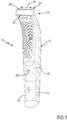
- Fig. 1 shows a perspective frontal view of a hair cutting appliance 10.
- the hair cutting appliance 10 is arranged as an appliance that is capable of both trimming and shaving.
- the appliance 10 comprises a housing 12 which is arranged in an elongated fashion. At the housing 12, a handle section 14 is defined. In the housing 12, a drive unit 16 is arranged. Further, a battery 18 may be arranged in the housing 12. In Fig. 1 , the drive unit 16 and the battery 18 are represented by dashed blocks. At the housing 12, operator controls 20 such as on/off buttons and the like may be provided.
- the appliance 10 comprises a processing head 24 that is attached to the housing 12.
- the processing head 24 comprises a blade set 26.
- the blade set 26, particularly a movable blade thereof, may be actuated and driven by the drive unit 16 in a reciprocating fashion, refer also to the double arrow 28 in Fig. 1 .
- respective teeth of the blades of the blade set 26 are moved with respect to one another, thereby effecting a cutting action.
- the blades of the blade set 26 may be arranged at a first leading edge 42 and, in at least some embodiments, at a second leading edge 44 that is opposite to the first leading edge 42.
- the first leading edge 42 maybe also referred to as frontal leading edge.
- a second leading edge 44 maybe also referred to as rear leading edge.
- blade sets 26, 126, 226 will be elucidated and described in more detail.
- the blade sets 26, 126, 226 may be attached to the appliance 10, or to a similar appliance. It goes without saying the single features disclosed in the context of a respective embodiment maybe combined with any of the other embodiments, also in isolated fashion, thereby forming further embodiments that still fall within the scope of the present disclosure.
- exemplary coordinate systems are shown for illustrative purposes.
- an X-axis is assigned to a longitudinal direction.
- a Y-axis is assigned to a lateral direction.
- a Z-axis is assigned to a vertical (height) direction.
- Respective associations of the axes/directions X, Y, Z with respective features and extensions of the blade set 26, 126, 226 can be derived from Fig. 2 , Fig. 6 and Fig. 11 .
- the coordinate system X, Y, Z is primarily provided for illustrative purposes and not intended to limit the scope of the disclosure.
- Fig. 2 shows a perspective top view of the blade set 26.
- the blade set 26 comprises a stationary blade 30 which may be also referred to as guard blade.
- a movable cutting arrangement 32 is provided which involves a movable blade 34, refer also to the side view of Fig. 3 and to the exploded perspective views of Fig. 4 and Fig. 5 .
- the mounting interface 36 involves two mounting arms that are provided with respective snap-lock elements 38.
- the blade set 26 maybe arranged in a snap-on mounting fashion involving a snap-on attachment in a releasable fashion.
- the blade set 26 may be coupled with a so-called swivel mechanism 40 which also forms part of the processing head 24.
- the swivel mechanism 40 provides the appliance 10 with an improved contour following capability. This involves that the blade set 26 maybe swiveled or pivoted in response to external forces. As a consequence, the blade set 26 may be more closely aligned with the skin contour of the user when the appliance 10 is used for shaving. Needless to say, alternative embodiments of appliances 10 may be envisaged wherein the blade set 26 is attached to the housing 12 in a relatively fixed fashion, i.e. without a swivel mechanism 40.
- the blade set 26 comprises a first leading edge 42 and a second leading edge 44.
- the first leading edge 42 is assigned to a first cutting side 46 which may be also referred to as frontal cutting side.
- the second leading edge 44 is assigned to a second cutting side 48 which may be also referred to as rear cutting side.
- the movable blade 34 that forms the movable cutting arrangement 32 involves a first movable cutting portion 52 and a second movable cutting portion 54.
- the first movable cutting portion 52 and the second movable cutting portion 54 are attached to one another and may be jointly actuated/moved with respect to the stationary blade 30.
- the blade set 26, particularly the stationary blade 30 thereof comprises a first cutting portion 58 and a second cutting portion 60.
- the first cutting portion 58 may be also referred to as trimming portion.
- the second cutting portion 60 may be also referred to as shaving portion.
- the second cutting portion 60 is rearwardly offset from the first cutting portion 58.
- the first cutting portion 58 is assigned to the respective leading edges 42, 44.
- the stationary blade 30 comprises a guard wall 66 defining a top side 64 of the blade set 26. At the top side 64, the stationary blade 30 faces the skin of the user when the appliance 10 is used for processing hair, particularly for shaving or styling operations.
- the stationary blade 30 is further composed of a bottom wall 68.
- an intermediate wall 70 is present which is arranged between the guard wall 66 and the bottom wall 68.
- the guard wall 66 and the bottom wall 68 are connected to one another at a tip region 72.
- the guard wall 66 in the bottom wall 68 define a U-shaped profile, the tip region 72 forming the basis thereof.
- the intermediate wall 70 also connects to the tip region 72.
- the blade set 26 comprises a so-called stepped processing zone 74.
- the stepped processing zone 74 defines and discriminates the first cutting portion 58 and the second cutting portion 60.
- first cutting portion 58 a greater thickness of the guard wall 66 than in the second cutting portion 60 is provided. This has the effect that, when the blade set 26 is moved in the longitudinal direction, first the first cutting portion 58 and subsequently the second cutting portion 60 contacts and processes the hair.
- the first cutting portion 58 cuts the hair in a trimming action, whereas the second cutting portion 60 chops the hair in a shaving action, due to their different effective wall thickness.
- the stationary blade 70 defines and provides a guide slot 76 for the movable cutting arrangement 32, particularly for the movable blade 34.
- a first guide slot 78 and a second guide slot 80 form the (overall) guide slot 76.
- the first guide slot 78 the first movable cutting portion 52 is arranged.
- the second guide slot 80 the second movable cutting portion 54 is arranged.
- respective teeth of the stationary blade 30 are designated by reference numeral 82.
- a respective series of teeth 82 is provided at each of the first leading edge 42 and the second leading edge 44.
- Each of the teeth 82 is defined by the guard wall 66, the bottom wall 68 and, if any, the intermediate wall 70, wherein the walls 66, 68, 70 are connected at respective tips 72.
- the movable cutting arrangement 32 is further detailed.
- the movable blade 34 is arranged as a layered blade, involving the first movable cutting portion 52 and the second movable cutting portion 54 which are arranged as respective (partial) blades.
- the first movable cutting portion 52 and the second movable cutting portion 54 are connected to one another, wherein so-called intermediate spacers 94 are arranged therebetween.
- the spacers 94 define an offset between the first movable cutting portion 52 and the second movable cutting portion 54 that is adapted to a vertical offset between the first guide slot 78 and the second guide slot 80.
- the intermediate spacers 94 are adapted to the thickness (vertical extension) of the intermediate wall 70.
- respective teeth 86 are provided.
- respective teeth 88 are provided.
- the teeth 86 are arranged in the first guide slot 78.
- the teeth 88 are arranged in the second guide slot 80.
- both the teeth 86 and the teeth 88 cooperate with the stationary blade teeth 82.
- the teeth 82 are assigned to both the first cutting portion 58 and the second cutting portion 60.
- the teeth 86 are assigned to the first cutting portion 58.
- the teeth 88 are assigned to the second cutting portion 60.
- the movable cutting arrangement 32 further involves a driving element which may be also referred to as driving bracket 100.
- a driving bracket 100 At the driving bracket 100, an engagement element 102 is provided.
- the engagement element 102 may be for instance arranged as an overmolding part.
- the driving bracket 100 maybe arranged as a metal part, wherein the engagement element 102 may be arranged as a plastic part.
- blade set 126 for a haircutting appliance 10 will be described and further detailed.
- the blade set 126 resembles the blade set 26 already discussed hereinbefore with reference to Figures 2 to 5 .
- a perspective view of the blade set 126 is provided, wherein for illustrative purposes no mounting interface and/or swivel mechanism is shown (refer also to Fig. 2 ).
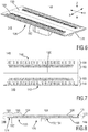
- the blade set 126 comprises a stationary blade 130, wherein a first leading edge 142 and a second leading edge 144 ( Fig. 7 ) are provided that are assigned to a first cutting side 146 and to a second cutting side 148, refer to Fig. 6 .
- the blade set 126 further comprises a movable cutting arrangement 132 implementing a movable blade 134, refer also to Fig. 9 .
- the movable cutting arrangement 132 comprises a first movable cutting portion 152 and a second movable cutting portion 154 which are shown in Fig. 10 in an exploded state. It is further noted in this context that embodiments of the movable cutting arrangement 132 maybe envisaged wherein the first movable cutting portion 152 and the second movable cutting portion 154 are integrally shaped, thereby forming a single movable blade 134. However, primarily for manufacturing and/or functional reasons, also a layered/stacked arrangement as shown in Fig. 10 maybe envisaged.
- a first cutting portion 158 and a second cutting portion 160 are provided, wherein the first movable cutting portion 152 is assigned to the first cutting portion 158, and wherein the second movable cutting portion 154 is assigned to the second cutting portion 160.
- the stationary blade 130 of the blade set 126 is also provided with a guard wall 166 facing a top side 164. Further, a bottom wall 168 is provided.
- the stationary blade 130 as shown in Fig. 8 does not incorporate an intermediate wall.
- the guard wall 166 and the bottom wall 168 are connected to one another at tips 172.
- the guard wall 166 and the bottom wall 168 define a lying U-shaped profile, seen in a lateral view as shown in Fig. 8 .
- the blade set 126 comprises a stepped processing zone 174 which involves a transition between the first cutting portion 158 and the second cutting portion 160.
- the guard wall 166 is considerably thick at the first cutting portion 158 and considerably thin at the second cutting portion 160.
- the guard wall 166 and the bottom wall 168 define a guide slot 176 therebetween.
- the guide slot 176 involves a first guide slot 178 arranged to receive the first movable cutting portion 152 and a second guide slot 180 arranged to receive the second movable cutting portion 154.
- the stationary blade 130 comprises respective teeth 182 that are assigned to the first cutting portion 158.
- the stationary blade 130 is further provided with stationary blade perforations 184.
- the perforations 184 are formed at the guard wall 166 and extend from the top side 164 to the guide slot 76.
- the perforations 184 are assigned to the second cutting portion 160.
- teeth 186 are formed at the first movable cutting portion 152 that are assigned to the first cutting portion 158. Hence, the teeth 186 cooperate with the teeth 182.
- perforations 190 are provided at the first movable cutting portion 152.
- perforations 192 are arranged at the second movable cutting portion 154. The perforations 190, 192 are congruent and in registry with one another. The perforations 190, 192 are assigned to the second cutting portion 160 and therefore arranged to cooperate with the perforations 184 of the stationary blade 130.
- the movable cutting arrangement 132 is provided with a driving bracket 200 and a respective engagement element 202 that is arranged to be formed at the driving bracket 200.
- the blade sets 26, 126 described hereinbefore are provided with two opposite leading edges 42, 44 and 142, 144, respectively.
- the blade set 226 is provided with a single leading edge 242 that is defining a single cutting side 246.
- the arrangement as discussed further below in connection with Fig. 11 to Fig. 15 maybe also involve a double-side arrangement including two leading edges.
- the embodiments as discussed hereinbefore with reference to Fig. 2 to Fig. 10 may be alternatively arranged as single-side blade sets including only one respective leading edge.
- the blade set 226 comprises a stationary blade 230.
- stationary blade teeth 282 are formed.
- the stationary blade 230 cooperates with a movable cutting arrangement 232 that incorporates a movable blade 234, refer also to Fig. 13 and Fig. 14 .
- the blade set 226 further includes a mounting interface 236 that comprises a receiving frame 238.
- respective lateral supports 320 are provided at respective lateral ends of the blade set 226.
- so-called bearing springs 240 are provided that connect the receiving frame 238 and a driving bracket 300 of the movable cutting arrangement 232, refer also to Fig. 15 .
- an engagement element 302 is formed that is arranged to cooperate with a driving lever 310.
- the driving lever 310 is arranged to be pivoted about a swivel axis 312 so as to drive the movable blade 234 of the movable cutting arrangement 232 with respect to the stationary blade 230.
- the movable blade 234 is composed of a first movable cutting portion 252 and a second movable cutting portion 254.
- the movable blade 234 comprises two separate movable cutting portions 252, 254 that are coupled with one another for a joint movement with respect to the stationary blade 230.
- a first cutting portion 258 and a second cutting portion 260 are provided.
- the first movable cutting portion 252 is assigned to the first cutting portion 258.
- the second movable cutting portion 254 is assigned to the second cutting portion 260.
- the stationary blade 230 comprises a guard wall 266 arranged at a top side 264 thereof. Further, a bottom wall 268 is provided which is formed in an inclined fashion with respect to the guard wall 266. The guard wall 266 and the bottom wall 268 are connected at respective tips 272.
- the blade set 226 further comprises a stepped processing zone 274 comprising a stepped shape of the guard wall 266.
- the guard wall 266 and the bottom wall 268 define therebetween a guide slot 276 comprising a first guide slot 278 and a second guide slot 280.
- the first guide slot 278 is arranged to receive the first movable cutting portion 252.
- the second guide slot 280 is arranged to receive the second movable cutting portion 254.
- stationary blade teeth 282 are provided that are assigned to both the first cutting portion 258 and the second cutting portion 260.
- first movable cutting portion 252 respective teeth 286 are provided.
- second movable cutting portion 254 respective teeth 288 are provided. The teeth 286 are assigned to the first cutting portion 258.
- the teeth 288 are assigned to the second cutting portion 260.
- Fig. 15 further illustrating the detailed structure of the movable cutting arrangement 232.
- Both the first movable cutting portion 252 and the second movable cutting portion 254 are arranged to be attached to the driving bracket 300.
- locator elements 306, 308 are formed at the driving element 300.
- the locators 306, 308 may engage respective recesses at the first movable cutting portion 252 and the second movable cutting portion 254.
- a spring bracket 304 is provided that is arranged to urge the second movable cutting portion 254 against the guard wall 266, refer also to Fig. 13 .
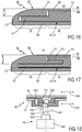
- FIG. 16 and Fig. 17 schematically illustrating a general layout of exemplary embodiments of a blade set 26 in accordance with the present disclosure.
- Fig. 16 shows a partial cross-sectional view of a blade set 26 that comprises a stationary blade 30 including a guard wall 66 and a bottom wall 68.
- Fig. 17 illustrates a partial cross-sectional view of a similar arrangement of a blade set 26 comprising a stationary blade 30 that further involves an intermediate wall 70 that is arranged between the guard wall 66 and the bottom wall 68 thereof.
- a first cutting portion 58 and a second cutting portion 60 is present to which a first movable cutting portion 52 and a second movable cutting portion 54 are assigned, respectively.
- an effective thickness or height of the guard wall 66 in the first cutting portion 58 is indicated by t 1 .
- an effective thickness of the guard wall 66 in the second cutting portion 60 is indicated in Fig. 16 and Fig. 17 by t 2 . It can be readily seen that the effective thickness t 1 is much greater than the effective thickness t 2 .
- the first cutting portion 58 is suited for trimming operations, whereas the second cutting portion 60 is considerably suited for shaving operations. Both cutting portions 58, 60 may cooperate to enable a combined trimming/shaving operation that, on the one hand, increases the cutting performance and, on the other hand, enables a close shaving and gives a smooth shaving sensation.
- the driving unit 16 involves a motor 330 to which a drive train 332 is coupled.
- the drive train 332 comprises driving shafts, gears, etc.
- an output shaft 334 is provided at an end of the drive train 332.
- the output shaft 334 comprises a first eccentric portion 336 and a second eccentric portion 338.
- a curved arrow designated by 340 indicates a rotating movement of the output shaft 334.
- the first eccentric portion 336 is coupled with a first engagement element 342.
- the second eccentric portion 338 is coupled with a second engagement element 344.
- the first eccentric portion 336 is coupled with the first movable cutting portion 52.
- the second eccentric portion 338 is coupled with the second movable cutting portion 54.
- a movable cutting arrangement 32 is provided which involves two movable cutting portions 52, 54 that are arranged to be moved independently from one another. Respective reciprocating movements are indicated in Fig. 18 by double-arrows 348, 346. When the first movable cutting portion 52 is moved to the right, the second movable cutting portion 54 is moved to the left.
Landscapes
- Life Sciences & Earth Sciences (AREA)
- Forests & Forestry (AREA)
- Engineering & Computer Science (AREA)
- Mechanical Engineering (AREA)
- Dry Shavers And Clippers (AREA)
Priority Applications (2)
| Application Number | Priority Date | Filing Date | Title |
|---|---|---|---|
| EP17165663.0A EP3388207A1 (fr) | 2017-04-10 | 2017-04-10 | Pale fixe, ensemble de pales et appareil de coupe de cheveux |
| PCT/EP2018/059151 WO2018189173A1 (fr) | 2017-04-10 | 2018-04-10 | Lame fixe, jeu de lames et appareil de coupe de cheveux |
Applications Claiming Priority (1)
| Application Number | Priority Date | Filing Date | Title |
|---|---|---|---|
| EP17165663.0A EP3388207A1 (fr) | 2017-04-10 | 2017-04-10 | Pale fixe, ensemble de pales et appareil de coupe de cheveux |
Publications (1)
| Publication Number | Publication Date |
|---|---|
| EP3388207A1 true EP3388207A1 (fr) | 2018-10-17 |
Family
ID=58536806
Family Applications (1)
| Application Number | Title | Priority Date | Filing Date |
|---|---|---|---|
| EP17165663.0A Withdrawn EP3388207A1 (fr) | 2017-04-10 | 2017-04-10 | Pale fixe, ensemble de pales et appareil de coupe de cheveux |
Country Status (2)
| Country | Link |
|---|---|
| EP (1) | EP3388207A1 (fr) |
| WO (1) | WO2018189173A1 (fr) |
Cited By (14)
| Publication number | Priority date | Publication date | Assignee | Title |
|---|---|---|---|---|
| USD914977S1 (en) | 2019-07-19 | 2021-03-30 | Church & Dwight Co., Inc. | Handle for hair removal apparatus |
| USD914978S1 (en) | 2019-10-18 | 2021-03-30 | Church & Dwight Co., Inc. | Hair removal apparatus |
| USD925830S1 (en) | 2019-07-19 | 2021-07-20 | Church & Dwight Co., Inc. | Head assembly for hair removal apparatus |
| US20210260783A1 (en) * | 2020-01-23 | 2021-08-26 | Braun Gmbh | Electric beard trimmer |
| EP3907045A1 (fr) * | 2020-05-08 | 2021-11-10 | Braun GmbH | Tondeuse électrique pour barbe |
| EP3907043A1 (fr) * | 2020-05-08 | 2021-11-10 | Braun GmbH | Tondeuse électrique pour barbe |
| USD936900S1 (en) | 2019-10-18 | 2021-11-23 | Church & Dwight Co., Inc. | Hair removal apparatus |
| USD940958S1 (en) | 2019-11-18 | 2022-01-11 | Church & Dwight Co., Inc. | Articulating blade assembly for hair removal device |
| USD942687S1 (en) | 2019-11-18 | 2022-02-01 | Church & Dwight Co., Inc. | Articulating blade assembly for hair removal device |
| USD952946S1 (en) | 2017-09-01 | 2022-05-24 | Church & Dwight Co., Inc. | Hair removal device |
| US11642802B2 (en) | 2020-05-08 | 2023-05-09 | Braun Gmbh | Electric beard trimmer |
| US11731294B2 (en) | 2020-01-23 | 2023-08-22 | Braun Gmbh | Electric beard trimmer |
| US11794362B2 (en) | 2020-01-23 | 2023-10-24 | Braun Gmbh | Electric beard trimmer |
| US11897151B2 (en) | 2020-01-23 | 2024-02-13 | Braun Gmbh | Electric beard trimmer |
Families Citing this family (3)
| Publication number | Priority date | Publication date | Assignee | Title |
|---|---|---|---|---|
| CN110480687B (zh) * | 2019-07-10 | 2024-04-16 | 珠海新秀丽家居用品有限公司 | 一种具有立体刀齿边的定刀及采用该定刀的鼻毛剪 |
| CN110193850A (zh) * | 2019-07-12 | 2019-09-03 | 元海医疗科技有限公司 | 刀片组及其二次成型的剃毛刀静刀 |
| TWI749939B (zh) * | 2020-12-08 | 2021-12-11 | 林忠信 | 具有封蓋的雙規格刀片手術前除毛刮刀 |
Citations (4)
| Publication number | Priority date | Publication date | Assignee | Title |
|---|---|---|---|---|
| GB415455A (en) * | 1932-03-26 | 1934-08-22 | Ernst Clemens Matthes | Improvements in hair clippers |
| GB501137A (en) * | 1937-03-02 | 1939-02-22 | Gen Shaver Corp | Improvements in or relating to shaving implements |
| US2251577A (en) * | 1938-07-22 | 1941-08-05 | Remington Rand Inc | Electric razor |
| WO2013150412A1 (fr) | 2012-04-03 | 2013-10-10 | Koninklijke Philips N.V. | Ensemble de lame pour appareil de coupe de cheveux et son procédé de fabrication |
-
2017
- 2017-04-10 EP EP17165663.0A patent/EP3388207A1/fr not_active Withdrawn
-
2018
- 2018-04-10 WO PCT/EP2018/059151 patent/WO2018189173A1/fr active Application Filing
Patent Citations (4)
| Publication number | Priority date | Publication date | Assignee | Title |
|---|---|---|---|---|
| GB415455A (en) * | 1932-03-26 | 1934-08-22 | Ernst Clemens Matthes | Improvements in hair clippers |
| GB501137A (en) * | 1937-03-02 | 1939-02-22 | Gen Shaver Corp | Improvements in or relating to shaving implements |
| US2251577A (en) * | 1938-07-22 | 1941-08-05 | Remington Rand Inc | Electric razor |
| WO2013150412A1 (fr) | 2012-04-03 | 2013-10-10 | Koninklijke Philips N.V. | Ensemble de lame pour appareil de coupe de cheveux et son procédé de fabrication |
Cited By (25)
| Publication number | Priority date | Publication date | Assignee | Title |
|---|---|---|---|---|
| USD952946S1 (en) | 2017-09-01 | 2022-05-24 | Church & Dwight Co., Inc. | Hair removal device |
| USD925830S1 (en) | 2019-07-19 | 2021-07-20 | Church & Dwight Co., Inc. | Head assembly for hair removal apparatus |
| USD914977S1 (en) | 2019-07-19 | 2021-03-30 | Church & Dwight Co., Inc. | Handle for hair removal apparatus |
| USD936900S1 (en) | 2019-10-18 | 2021-11-23 | Church & Dwight Co., Inc. | Hair removal apparatus |
| USD914978S1 (en) | 2019-10-18 | 2021-03-30 | Church & Dwight Co., Inc. | Hair removal apparatus |
| USD936899S1 (en) | 2019-10-18 | 2021-11-23 | Church & Dwight Co., Inc. | Hair removal apparatus |
| USD942687S1 (en) | 2019-11-18 | 2022-02-01 | Church & Dwight Co., Inc. | Articulating blade assembly for hair removal device |
| USD940958S1 (en) | 2019-11-18 | 2022-01-11 | Church & Dwight Co., Inc. | Articulating blade assembly for hair removal device |
| US11633868B2 (en) * | 2020-01-23 | 2023-04-25 | Braun Gmbh | Electric beard trimmer |
| US20210260783A1 (en) * | 2020-01-23 | 2021-08-26 | Braun Gmbh | Electric beard trimmer |
| US11897151B2 (en) | 2020-01-23 | 2024-02-13 | Braun Gmbh | Electric beard trimmer |
| US11794362B2 (en) | 2020-01-23 | 2023-10-24 | Braun Gmbh | Electric beard trimmer |
| US11731296B2 (en) | 2020-01-23 | 2023-08-22 | Braun Gmbh | Electric beard trimmer |
| US11731294B2 (en) | 2020-01-23 | 2023-08-22 | Braun Gmbh | Electric beard trimmer |
| EP3907044A1 (fr) * | 2020-05-08 | 2021-11-10 | Braun GmbH | Tondeuse électrique pour barbe |
| EP3907043A1 (fr) * | 2020-05-08 | 2021-11-10 | Braun GmbH | Tondeuse électrique pour barbe |
| EP3907045A1 (fr) * | 2020-05-08 | 2021-11-10 | Braun GmbH | Tondeuse électrique pour barbe |
| CN115515766A (zh) * | 2020-05-08 | 2022-12-23 | 博朗有限公司 | 电动胡须修剪器 |
| EP3907047A1 (fr) * | 2020-05-08 | 2021-11-10 | Braun GmbH | Tondeuse électrique pour barbe |
| US11642802B2 (en) | 2020-05-08 | 2023-05-09 | Braun Gmbh | Electric beard trimmer |
| WO2021224848A1 (fr) * | 2020-05-08 | 2021-11-11 | Braun Gmbh | Tondeuse électrique à barbe |
| EP3907046A1 (fr) * | 2020-05-08 | 2021-11-10 | Braun GmbH | Tondeuse électrique pour barbe |
| WO2021224851A1 (fr) * | 2020-05-08 | 2021-11-11 | Braun Gmbh | Tondeuse électrique à barbe |
| US11865733B2 (en) | 2020-05-08 | 2024-01-09 | Braun Gmbh | Electric beard trimmer |
| WO2021224852A1 (fr) * | 2020-05-08 | 2021-11-11 | Braun Gmbh | Tondeuse électrique à barbe |
Also Published As
| Publication number | Publication date |
|---|---|
| WO2018189173A1 (fr) | 2018-10-18 |
Similar Documents
| Publication | Publication Date | Title |
|---|---|---|
| EP3388207A1 (fr) | Pale fixe, ensemble de pales et appareil de coupe de cheveux | |
| US20220274271A1 (en) | Attachment comb, cutting head and hair cutting appliance | |
| RU2651550C1 (ru) | Режущая головка и устройство для срезания волос | |
| JP6564099B2 (ja) | リンクユニット及び毛切断機器 | |
| US10279492B2 (en) | Coupling mechanism for a drive train of a hair cutting appliance | |
| US11370134B2 (en) | Stationary blade, blade set, and manufacturing method | |
| US11597107B2 (en) | Processing head for a hair cutting appliance and combined blade unit | |
| JP6126750B2 (ja) | 毛切断機器及びブレードセット | |
| RU2714560C2 (ru) | Неподвижный нож, набор ножей и бытовой прибор для стрижки волос | |
| US9533422B2 (en) | Hair removal apparatus | |
| EP3071375B1 (fr) | Unité de montage et appareil de coupe de cheveux | |
| EP3388208A1 (fr) | Lame fixe, ensemble de lames et appareil pour couper les cheveux | |
| JP6889250B2 (ja) | ひげ用トリマー | |
| WO2016124484A1 (fr) | Tête de coupe et appareil de coupe de poils | |
| WO2015049137A1 (fr) | Ensemble de lames et appareil à couper les cheveux | |
| CN102528830B (zh) | 理发器 | |
| JPH0446156B2 (fr) | ||
| CN211541310U (zh) | 修剪刀剃须刀一体刀头及刀具 |
Legal Events
| Date | Code | Title | Description |
|---|---|---|---|
| PUAI | Public reference made under article 153(3) epc to a published international application that has entered the european phase |
Free format text: ORIGINAL CODE: 0009012 |
|
| AK | Designated contracting states |
Kind code of ref document: A1 Designated state(s): AL AT BE BG CH CY CZ DE DK EE ES FI FR GB GR HR HU IE IS IT LI LT LU LV MC MK MT NL NO PL PT RO RS SE SI SK SM TR |
|
| AX | Request for extension of the european patent |
Extension state: BA ME |
|
| STAA | Information on the status of an ep patent application or granted ep patent |
Free format text: STATUS: THE APPLICATION HAS BEEN WITHDRAWN |
|
| 18W | Application withdrawn |
Effective date: 20190531 |