EP3387219B1 - Imbohrlochwerkzeug zur detektion von rohrlecks - Google Patents
Imbohrlochwerkzeug zur detektion von rohrlecks Download PDFInfo
- Publication number
- EP3387219B1 EP3387219B1 EP16809059.5A EP16809059A EP3387219B1 EP 3387219 B1 EP3387219 B1 EP 3387219B1 EP 16809059 A EP16809059 A EP 16809059A EP 3387219 B1 EP3387219 B1 EP 3387219B1
- Authority
- EP
- European Patent Office
- Prior art keywords
- downhole tool
- wave generator
- outside fluid
- generator device
- waves
- Prior art date
- Legal status (The legal status is an assumption and is not a legal conclusion. Google has not performed a legal analysis and makes no representation as to the accuracy of the status listed.)
- Not-in-force
Links
Images






Classifications
-
- E—FIXED CONSTRUCTIONS
- E21—EARTH OR ROCK DRILLING; MINING
- E21B—EARTH OR ROCK DRILLING; OBTAINING OIL, GAS, WATER, SOLUBLE OR MELTABLE MATERIALS OR A SLURRY OF MINERALS FROM WELLS
- E21B47/00—Survey of boreholes or wells
- E21B47/10—Locating fluid leaks, intrusions or movements
- E21B47/107—Locating fluid leaks, intrusions or movements using acoustic means
-
- G—PHYSICS
- G01—MEASURING; TESTING
- G01S—RADIO DIRECTION-FINDING; RADIO NAVIGATION; DETERMINING DISTANCE OR VELOCITY BY USE OF RADIO WAVES; LOCATING OR PRESENCE-DETECTING BY USE OF THE REFLECTION OR RERADIATION OF RADIO WAVES; ANALOGOUS ARRANGEMENTS USING OTHER WAVES
- G01S11/00—Systems for determining distance or velocity not using reflection or reradiation
- G01S11/14—Systems for determining distance or velocity not using reflection or reradiation using ultrasonic, sonic or infrasonic waves
-
- G—PHYSICS
- G01—MEASURING; TESTING
- G01S—RADIO DIRECTION-FINDING; RADIO NAVIGATION; DETERMINING DISTANCE OR VELOCITY BY USE OF RADIO WAVES; LOCATING OR PRESENCE-DETECTING BY USE OF THE REFLECTION OR RERADIATION OF RADIO WAVES; ANALOGOUS ARRANGEMENTS USING OTHER WAVES
- G01S15/00—Systems using the reflection or reradiation of acoustic waves, e.g. sonar systems
- G01S15/88—Sonar systems specially adapted for specific applications
- G01S15/89—Sonar systems specially adapted for specific applications for mapping or imaging
-
- G—PHYSICS
- G01—MEASURING; TESTING
- G01S—RADIO DIRECTION-FINDING; RADIO NAVIGATION; DETERMINING DISTANCE OR VELOCITY BY USE OF RADIO WAVES; LOCATING OR PRESENCE-DETECTING BY USE OF THE REFLECTION OR RERADIATION OF RADIO WAVES; ANALOGOUS ARRANGEMENTS USING OTHER WAVES
- G01S5/00—Position-fixing by co-ordinating two or more direction or position line determinations; Position-fixing by co-ordinating two or more distance determinations
- G01S5/18—Position-fixing by co-ordinating two or more direction or position line determinations; Position-fixing by co-ordinating two or more distance determinations using ultrasonic, sonic or infrasonic waves
- G01S5/30—Determining absolute distances from a plurality of spaced points of known location
Definitions
- the invention is related to a downhole tool for leak detection especially in well bores.
- Well bores are used in the petroleum and natural gas industry to produce hydrocarbons (production well) or to inject fluids, for example water, CO 2 and/or Nitrogen (injection well).
- fluids for example water, CO 2 and/or Nitrogen (injection well).
- injection well typically, such fluids are injected to stimulate, i.e. to enhance the hydrocarbon recovery.
- CO 2 injection has been introduced to this to reduce the CO 2 -concentration in the atmosphere in order to defeat global warming.
- a well bore is lined with a steel pipe or steel tubing, generally referred to as casing or liner, and cemented in the overburden section to reduce the risk of unwanted evacuation of fluids from the overburden and/or the reservoir into the surface environment.
- casing or liner For completion of the reservoir section at present several options are typically used, namely open hole completion, or using a liner with several formation packers for sealing off sections of the annulus around the steel liner, or using a steel liner which is cemented in place and access to the reservoir is gained by perforating the liner and cement in a later stage of the completion, or completion of the well with a liner in open hole which has predrilled holes in the liner to gain access to the reservoir. It should be noted that the holes can also be made in a later stage of the well life.
- the well bore can enlarge due to chemical reactions and/or an instability of the borehole. This may occur due to injection or production pressure changes and/or erosion which can take place e.g. in case of production from unstable geological formations such as turbidites known for their unpredictable sand face failure resulting in massive sand production leading to well failure. Furthermore, when injection processes are being used fractures can be generated resulting in undesired direct communication between the injection and production wells. On the other hand the well can collapse, for example caused by compaction, a process which happens when the pressure in the reservoir reduces, or by the use of chemicals used to improve injectivity or productivity.
- the well bore and/or the casing or liner and/or the reservoir section may, for example, be subject to inspection e.g. in order to verify physical properties such as pressure or temperature, more general to collect information about the status, or in order to observe defects or anomalies, in particular in order to prevent collapses of all kind of the well.
- the total length from the reservoir to an access at the top end of the well bore may sum up to several hundred or even several thousand meters retrieving such data, e.g. to an extraction facility at said access, is difficult and subject to continued development.
- European Patent application 2 587 227 A1 shows a downhole tool for determining flow velocity of fluid an inside of a borehole. It comprises a longitudinal transducer to measure longitudinal flow velocity of the fluid flow in the wellbore.
- US Patent 4 947 683 shows a measuring device for use in a producing well. It comprises a piezoelectric transmitter and receiver to find reflective interfaces like gas bubbles droplets and particles in order to measure the flow velocity of the fluid flow in the producing well.
- abnormalities in the surrounding surface of the well bore e.g. the surface of the casing/liner or, if no casing/liner is in place, the surface of the surrounding earth material, which is the drill channel, where the well bore is drilled through.
- Such abnormalities can e.g. be a crack or any kind of opening to the surrounding earth material, where well bore fluid may escape from or stream into the well bore.
- Yet another aspect of the object of the invention is to improve the limitations mentioned above.
- the downhole tool which achieves the object of the invention and which is presented here comprises a specialized detection system which is capable of measuring crossflows or inhomogeneities in the stream of well bore fluid in the well bore.
- the downhole tool being adapted to horrge an outside fluid flow and which further is adapted to operate in a well bore, comprises a housing which is surrounded by an outside fluid.
- the outside fluid typically is the well bore fluid.
- the downhole tool further comprises at least a first wave generator device for coupling waves into the surrounding outside fluid.
- the first wave generator device is, by way of example, arranged at a frontside of the housing.
- the arrangement of the first wave generator device influences the measurement sensitivity with respect to the measurable flow direction.
- a measurement of fluid flow of the outside fluid in a translational direction is eased. In other words, the measurement of the longitudinal fluid flow along the well bores extension direction is eased.
- the first wave generator device when the first wave generator device is positioned at a side of the downhole tool which is facing towards the sidewall of the well bore or the casing/liner, it is possible, that e.g. measurement of a crossflow in the outside fluid is eased.
- the waves coupled into the outside fluid can comprise a single wave motion, e.g. a ping-like short-term signal.
- the waves coupled into the outside fluid can also be composed of a sinusoidal signal, e.g. a tone which may have a certain pitch and/or loudness, e.g. in the region of ultrasound signals. Ultrasound signals are preferred due to their comparatively long range in fluid.
- the waves generated by the first wave generator device are scattered, e.g. reflected, at inhomogeneities in the outside fluid.
- inhomogeneities can be for example particles, scatterers and/or water in oil.
- inhomogeneities are present in a vast number throughout the outside fluid, so that enough inhomogeinities are present in the measurement range of the downhole tool.
- a receiver device is installed at the downhole tool for receiving said reflections.
- the receiver device therefore may comprise a membrane which is excited by the reflections. It is possible, that the first wave generator device and the receiver device is one same device.
- the downhole tool further comprises an evaluation device for determining first positions of said inhomogeneities in the outside fluid by evaluating said reflections, wherein the evaluation device is adapted to determine the outside fluid flow.
- the evaluation device may for example comprise a trigger for capturing the event in time of coupling said waves into said outside fluid. In other words, releasing said waves into said outside fluid releases said trigger, which trigger runs until a second event occurs. The second event can then be the detection of the reflection by the receiver device.
- the evaluation device is connected to the receiver device and reads out the signal received by the receiver device.
- the evaluation device advantageously determines the first positions of said inhomogeneities by measuring an elapsed time between coupling said waves into the surrounding outside fluid using said wave generator device and receiving said reflections using said receiver device. For example, By analysing the trigger runtime from the trigger start when coupling said waves into the surrounding outside fluid until receiving said signal from the receiver device, a distance to said inhomogeneity is detectable.
- the evaluation device advantageously further determines second positions of said inhomogeneities by again measuring an elapsed time between coupling second waves into the surrounding outside fluid and receiving second reflections. By comparing the first positions with the second positions a movement of the inhomogeneities may be tracked or noticed.
- the evaluation device further may be able to evaluate position changes of said inhomogeneities, preferably to evaluate a position and/or velocity pattern of the inhomogeneities, by comparing said first positions with said second positions.
- the evaluation device gathers data from the wave generator device(s), e.g. the sending time of the coupling wave, it gathers further data from the receiver device, e.g. the time of receiving reflections.
- the evaluation device e.g. then calculates first and second positions, e.g. distances in relation to the downhole tool, from said inhomogeneities, and thus is able to e.g. calculate velocity and/or mass flow rates of fluid flows in the well bore.
- the evaluation device thus also takes into account the velocity of the downhole tool itself moving in the well bore, and/or it takes into account a known longitudinal fluid velocity of the outside fluid flowing along the well bore extension direction to thus obtain resulting transverse velocity components of movement, which is e.g. cross flows.
- a cross flow can be any transverse movement of the fluid flow perpendicular to the longitudinal fluid flow which flows along the extension direction of the well bore.
- the downhole tool may thus comprise calculation of an outside fluid flow velocity and/or a crossflow in the outside fluid and/or a fluid amount (mass flow rate) entering the well bore or escaping out of the well bore through an undesired opening or crack in the well bore.
- the evaluation device may be designed to detect a variation of the position and/or velocity pattern of the inhomogeneities in the outside fluid, thereby identifying translationally movement of the outside fluid and/or alterations of the structure of the well bore and/or a direction depending fluid flow.
- the correlation coefficient between the first position(s) and the second position(s) is determined, which is expressed, by way of example, by the cross autocorrelation function.
- the first wave generator device comprises a directional sound generator.
- the directional sound generator generates sound waves with a predefined emission direction, or an emission cone which has a limited range of emission direction, so that additional direction information is obtainable when evaluating said reflections.
- the downhole tool according to the invention comprises a second wave generator device, which may include a directional sound generator.
- the second wave generator device is oriented such, that it emits its waves with a beam angle with respect to the waves of the first wave generator device.
- the receiver device may then be also adapted to receive reflections from waves from the second wave generator device.
- the second wave generator device is adapted to also receive waves coupled into the outside fluid, so that the second wave generator device can receive the waves it released.
- the second wave generator device can be a combined wave generator and receiver device.
- the evaluation device then is adapted to also evaluate a second velocity and position pattern derived from the second positions and/or a difference between the first and the second positions.
- the downhole tool can further comprise a third wave generator device having a directional sound generator for coupling waves into the outside fluid, the third wave generator device comprising a predefined beam angle with respect to the first wave generator device and also a predefined beam angle to the second wave generator device.
- the beam direction of the wave generator device and/or of the second wave generator device and/or of the third wave generator device can be designed to be adjustable thereby allowing to adjust the beam angle in between the wave generator devices.
- the measurement accuracy can be high at close distances or high with inhomogeneities farther away from the downhole tool.
- the wave generator devices may advantageously be arranged in a common plane, e.g. at one side of the downhole tool.
- the wave generator devices are arranged such, that one specific inhomogeneity, e.g. a specific particle in the outside fluid, is "scanned” (or detected) with more than one wave generator device, so that at least two different set of informations, e.g. each regarding distance and velocity of said inhomogeneity, are available for further processing.
- one specific inhomogeneity e.g. a specific particle in the outside fluid
- the directional sound generator may be composed by a transducer.
- a transducer may comprise a membrane being in contact with an outer side with the outside fluid and having mounted at an inner side of the membrane e.g. an electromechanic membrane driver.
- the downhole tool advantageously is designed for being deployed in a production well and/or for being deployed in an injection well.
- the wave generator device and/or the second wave generator device and/or the further wave generator device may be designed to couple ultrasonic sound waves into the outside fluid.
- the downhole tool being adapted to operate in the well bore fluid in a well bore may further comprise an elongated housing which is adapted for operation in an elongated well bore.
- the downhole tool may be part of a multifunctional downhole tool which, for example, collects data in the well bore and/or the reservoir or which operates other functions particularly for sustaining the well bore, e.g. does cementations of an outer wall of the well bore or the like.
- the downhole tool can also comprise the functionality of a communication equipment in order to exchange data e.g. with a central station in the extraction facility.
- a well bore 2 is drilled in an earth formation 4 to exploit natural resources like oil or gas.
- the well bore 2 continuously extends from the extraction facility 9 at or near the surface 6 to a reservoir 8 of the well bore 2 situated distal from the wellhead 10 at the extraction facility 9.
- a casing/liner 12 in the form of an elongated steel pipe or steel tubing is located within the well bore 2 and extending from the wellhead 10 to an underground section of the well bore 2.
- the reservoir 8 and/or the casing/liner 12 are typically filled with a fluid 16, 17, 18, respectively.
- the fluids 16, 17, 18 are e.g. oil or gas in case of a production well or water, CO 2 or nitrogen in case of an injection well.
- a downhole tool 20 is located within the casing or liner 12.
- the downhole tool 20 operates autonomously having internal power storage 92 (see e.g. Fig. 2 ) and thus needs not be powered or wired externally.
- the downhole tool 20 can be operated quite freely in the well bore 2 and particularly needs not to be cable linked to the surface.
- the downhole tool 20 may additionally be a movable downhole tool 20 being moved by moving means 21, generally known to the skilled person, within the casing or liner 12 to any desired position in the casing or liner 12 or even in the reservoir 8.
- the downhole tool 20 is equipped with a first wave generator device 30 which couples a wave 32 into the outside fluid to detect and/or track a particle 60 in the outside fluid.
- Fig. 2 shows another earth formation with a downhole tool 20 positioned in a horizontal portion of the casing/liner 12.
- the liner 12 in this embodiment only partly covers the well bore.
- the downhole tool 20 comprises a power supply 92.
- Fig. 3 depicts a sideview of a downhole tool 20 in a well bore 2, the downhole tool 20 having a first wave generator device 30 at a side of the downhole tool 20.
- the first wave generator device couples waves 32 into the outside fluid 18. While propagating through the outside fluid 18 the waves 32 can hit inhomogeinities 60, such as particles of any kind which are worn by the outside fluid 18. In other words, the particles 60 are used as markers indicating the movement of the outside fluid 18, e.g. the velocity in the case of one-dimensional analysis, which happens to be an easy way of measurement when one wave generator device 30 is used.
- the waves 32 e.g. ultrasound waves 32
- the waves 32 are reflected or more generally scattered, at said inhomogeneities 60 thereby generating new waves at said inhomogeneities 60.
- These new waves are referred to as reflections 70.
- Fig. 3 As can be seen in Fig. 3 at several inhomogeneities 60 reflections 70 are indicated. These particles 60 together form a group of particles 72 or a pattern 72.
- the downhole tool 20 is capable of observing whether the pattern 72 keeps its structure or whether the inhomogeneities 60 show a movement in relation to each other, thereby altering the pattern 72.
- Fig. 4 indicates at most the same system as described with respect to Fig. 3 , but the inhomogeneities 60 have moved in the longitudinal fluid flow. So to say, the inhomogeneities 60 have moved towards the downhole tool 20.
- the downhole tool 20 also detects the pattern 72, it is capable of observing, that, in this case, no intra-pattern-movement is present, as the pattern 72 is unamended and only translationally moved with respect to the downhole tool 20 and/or with respect to the well bore 2.
- the downhole tool 20 is able to measure the flow of the outside fluid 18 with a single transducer, which is the first wave generator device 30, by monitoring the particle induced reflections.
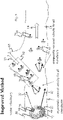
- Fig. 5 shows another embodiment of the downhole tool 20 deployed in a well bore 2 having a leakage 65.
- a longitudinal fluid flow direction 14 is indicated depicting the "main flow” in the well bore 2, or in other words, the "wanted flow”.
- Another fluid flow direction 15 at the leakage 65 indicates a fluid flow not pointing towards the same direction as the longitudinal fluid flow direction 14.
- the other fluid flow direction 15 shows a transverse component of translation with respect to the longitudinal fluid flow direction 14.
- the other fluid flow direction 15 to the leakage 65 may be a cross flow 15.
- the downhole tool 20 in the embodiment of Fig. 5 comprises two wave generators 30, 40, where the first wave generator 30 couples waves 32 into the outside fluid 18 and the second wave generator 40 couples waves 42 into the outside fluid 18.
- the waves 32, 43 can have identical properties, but it is preferred to e.g. allow identification of specific wave by using a different tune or pulse width or the like.
- each wave generator device 30, 40 is a combined wave generator and detection device 25, 30, 40.
- the downhole tool 20 is capable of determining vectoriel velocity components for each of the inhomogeneities 60.
- the downhole tool 20 of Fig. 5 further comprises an evaluation device 27 for evaluating e.g. fluid flow velocity components.
- the evaluation device 27 further can determine the particle pattern 62.
- Fig. 6 shows an experimental setup of an experimental downhole tool 20a in an experimental well bore 2a for determination of downhole tool properties.
- An outside fluid 18 is filled in the experimental well bore 2a, the outside fluid 18 comprising inhomogeneities 60 to be detected by the downhole tool 20a.
- Fig. 7 shows a close look of the frontside of the downhole tool 20a showing three wave generator devices 30, 40, 50.
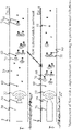
- Fig. 8 shows a schematical setup of the measurement principle.
- the downhole tool 20 comprises the first, the second and a third wave generator device 30, 40, 50.
- Each wave generator device 30, 40, 50 couples waves into the outside fluid 18.
- Inhomogeneities 60, or particles 60, are present in the outside fluid 18.
- the particles 60 comprise a particle velocity, whereas the particle velocity can be divided into directional velocity components, such as the velocity v of the particle in the direction of the sensor.
- t i indicates the echo delay, which is the time between coupling the wave into the outside fluid 18 and receiving the reflection 70 at the downhole tool 20. For example, for one specific particle moving in time from position 60' to position 60", e.g. coming closer to the downhole tool 20 as shown in Fig.
- a first echo delay indicated by t 1 is measured at a first point in time
- a second echo delay indicated by t 2 is measured at a second point in time which is after the first point in time.
- an suction pump 65a is installed as a leakage 65.
- a crossflow 15 thereby is generated inside the (experimental) well bore 2a.
- the experimental cross flow generates a leakage of 700ml/s.
- a rotor generates a constant longitudinal fluid flow direction 14, which is comparable to the longitudinal fluid flow 14 in a well bore 2.
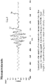
- Fig. 10 shows the result of evaluating with the evaluation device 27 fluid flow velocity components of the outside fluid with a first, a second and a third wave generator device 30, 40, 50.
- the downhole tool 20a is moved along the well bore 2a passing a leakage 65.
- Fig. 11 shows another result of evaluating with the evaluation device 27 fluid flow velocity components of the outside fluid when passing a leakage 65 with the downhole tool 20a.
- a downhole tool 20 which is capable of identifying disturbances, leakages 65 or other losses of fluid flow in a well bore 2 is presented.
- the downhole tool 20 uses a direction dependent flow measurement system and implements speckle tracking.
- speckle tracking By way of example, in a well bore having an oil production of 10,000 barrel per day (equals to 1,589.873 m 3 per day or 0.018 m 3 /s) a typical longitudinal fluid flow of about 18 l/s is reached corresponding to a fluid position change of 400 mm/s. It is desired to keep this fluid flow as constant as possible, e.g. detecting fluid flow deviations bigger than 5 %, which is bigger than 0.9 l/s. Such fluid flow measurement using speckle tracking is successfully demonstrated with the experimental setup. A direction depending flow measurement is possible. Thus, a detection of a leakage 65 in a well bore 2 is possible with the presented downhole tool 20.
Landscapes
- Physics & Mathematics (AREA)
- Engineering & Computer Science (AREA)
- Radar, Positioning & Navigation (AREA)
- Remote Sensing (AREA)
- Life Sciences & Earth Sciences (AREA)
- Geology (AREA)
- Mining & Mineral Resources (AREA)
- General Physics & Mathematics (AREA)
- Acoustics & Sound (AREA)
- Fluid Mechanics (AREA)
- Geochemistry & Mineralogy (AREA)
- General Life Sciences & Earth Sciences (AREA)
- Environmental & Geological Engineering (AREA)
- Geophysics (AREA)
- Computer Networks & Wireless Communication (AREA)
- Investigating Or Analyzing Materials By The Use Of Ultrasonic Waves (AREA)
- Geophysics And Detection Of Objects (AREA)
Claims (15)
- Bohrlochwerkzeug (20) zum Untersuchen eines äußeren Fluidstroms, das dafür ausgebildet ist, in einem Bohrloch (2) betrieben zu werden, umfassend:▪ ein Gehäuse (28), das von einem äußeren Fluid (16, 17, 18) umgeben ist,▪ mindestens eine erste Wellengeneratoreinrichtung (30), vorzugsweise mit einem Richtschallgenerator, zum Einkoppeln von Wellen (32) in das umgebende äußere Fluid (16, 17, 18),▪ eine zweite Wellengeneratoreinrichtung (40), wobei die zweite Wellengeneratoreinrichtung (40) einen Abstrahlwinkel in Bezug auf die erste Wellengeneratoreinrichtung (30) aufweist,▪ wobei die Wellen (32) von der ersten und der zweiten Wellengeneratoreinrichtung an Inhomogenitäten (60) in dem äußeren Fluid (16, 17, 18) wie beispielsweise Partikeln, Streukörpern und/oder Wasser in Öl, gestreut, z.B. reflektiert, werden und dabei Reflexionen (70) erzeugen,▪ eine Empfängereinrichtung (25) zum Empfangen der Reflexionen (70),▪ eine Auswerteeinrichtung (27) zum Bestimmen erster Positionen der Inhomogenitäten (60) in dem äußeren Fluid (16, 17, 18) durch Auswerten der Reflexionen (70), wobei die Auswerteeinrichtung (27) dazu eingerichtet ist, die äußere Fluidströmung zu bestimmen.
- Bohrlochwerkzeug (20) nach dem vorhergehenden Anspruch,
wobei die Auswerteeinrichtung (27) einen Auslöser zum Erfassen eines Ereignisses zum Zeitpunkt des Einkoppelns der Wellen (32) in das äußere Fluid (16, 17, 18) umfasst. - Bohrlochwerkzeug (20) nach einem der vorhergehenden Ansprüche, wobei die Auswerteeinrichtung (27) dazu eingerichtet ist, die ersten Positionen der Inhomogenitäten (60) zu bestimmen, indem eine Zeit gemessen wird, die zwischen dem Einkoppeln der Wellen (32) in das umgebende äußere Fluid (16, 17, 18) mittels der Wellengeneratoreinrichtung (30) und dem Empfangen der Reflexionen (70) mittels der Empfängereinrichtung (25) verstrichen ist.
- Bohrlochwerkzeug (20) nach dem vorhergehenden Anspruch,wobei die Auswerteeinrichtung ferner dazu eingerichtet ist, zweite Positionen der Inhomogenitäten (60) zu bestimmen, indem wiederum eine verstrichene Zeit zwischen dem Einkoppeln zweiter Wellen (32) in das umgebende äußere Fluid (16, 17, 18) und dem Empfangen zweiter Reflexionen (70) gemessen wird,wobei die Auswerteeinrichtung (27) ferner dazu eingerichtet ist, durch Vergleichen der ersten Positionen mit den zweiten Positionen Positionsänderungen der Inhomogenitäten (60), vorzugsweise ein Positions- und/oder Geschwindigkeitsmuster (62) der Inhomogenitäten (60), auszuwerten.
- Bohrlochwerkzeug (20) nach einem der vorhergehenden Ansprüche,
wobei die Auswerteeinrichtung ferner dazu eingerichtet ist, eine Strömungsgeschwindigkeit (14, 15) des äußeren Fluids und/oder eine Querströmung (15) in dem äußeren Fluid und/oder eine in das Bohrloch (2) eintretende oder aus dem Bohrloch (2) durch eine ungewollte Öffnung oder einen Riss (65) in dem Bohrloch (2) austretende Fluidmenge zu berechnen. - Bohrlochwerkzeug (20) nach einem der vorhergehenden Ansprüche,
wobei die Auswerteeinrichtung (27) dazu eingerichtet ist, eine Änderung des Positions- und/oder Geschwindigkeitsmusters (62) zu erkennen und dadurch eine Translationsbewegung des äußeren Fluids (16, 17, 18) und/oder Änderungen der Struktur des Bohrlochs (2) und/oder eine richtungsabhängige Fluidströmung (14, 15) zu identifizieren. - Bohrlochwerkzeug (20) nach einem der vorhergehenden Ansprüche,
wobei ein Korrelationskoeffizient zwischen der ersten Position und der zweiten Position bestimmt wird, z. B. eine Kreuzautokorrelationsfunktion. - Bohrlochwerkzeug (20) nach einem der vorhergehenden Ansprüche,
wobei die erste Wellengeneratoreinrichtung (30) einen Richtschallgenerator umfasst und wobei die zweite Wellengeneratoreinrichtung (40) einen Richtschallgenerator umfasst. - Bohrlochwerkzeug (20) nach dem vorhergehenden Anspruch,wobei die Empfängereinrichtung (25) außerdem dazu eingerichtet ist, Reflexionen (70) von Wellen (42) von der zweiten Wellengeneratoreinrichtung (40) zu empfangen,wobei die Auswerteeinrichtung (27) dazu eingerichtet ist, auch ein aus den zweiten Positionen und/oder aus einer Differenz zwischen den ersten und den zweiten Positionen abgeleitetes zweites Geschwindigkeits- und Positionsmuster (62) auszuwerten.
- Bohrlochwerkzeug (20) nach einem der vorhergehenden Ansprüche,
ferner umfassend eine dritte Wellengeneratoreinrichtung (50) mit einem Richtschallgenerator zum Einkoppeln von Wellen in das äußere Fluid (16, 17, 18), wobei die dritte Wellengeneratoreinrichtung (50) einen vorgegebenen Abstrahlwinkel in Bezug auf die erste Wellengeneratoreinrichtung (30) und einen vorgegebenen Abstrahlwinkel zu der zweiten Wellengeneratoreinrichtung (40) aufweist. - Bohrlochwerkzeug (20) nach Anspruch 9 oder 10,
wobei die Abstrahlrichtung der Wellengeneratoreinrichtung (30) und/oder der zweiten Wellengeneratoreinrichtung (40) und/oder der dritten Wellengeneratoreinrichtung (50) einstellbar ist, wodurch eine Einstellung des Abstrahlwinkels zwischen den Wellengeneratoreinrichtungen (30, 40, 50) möglich ist. - Bohrlochwerkzeug (20) nach einem der Ansprüche 9, 10 oder 11,
wobei die Wellengeneratoreinrichtungen (30, 40, 50) in einer gemeinsamen Ebene auf einer Seite des Bohrlochwerkzeugs (20) angeordnet sind. - Bohrlochwerkzeug (20) nach einem der vorhergehenden Ansprüche,
wobei der Richtschallgenerator ein Wandler ist. - Bohrlochwerkzeug (20) nach einem der vorhergehenden Ansprüche,
wobei das Bohrlochwerkzeug (20) zum Einsatz in einem Produktionsbohrloch geeignet ist oder zum Einsatz in einem Injektionsbohrloch geeignet ist. - Bohrlochwerkzeug (20) nach einem der vorhergehenden Ansprüche,
wobei die Wellengeneratoreinrichtung (30) und/oder die zweite Wellengeneratoreinrichtung (40) und/oder die dritte Wellengeneratoreinrichtung (50) dazu eingerichtet ist/sind, Ultraschallwellen (32, 42) in das äußere Fluid (16, 17, 18) einzukoppeln.
Applications Claiming Priority (2)
| Application Number | Priority Date | Filing Date | Title |
|---|---|---|---|
| GBGB1521864.7A GB201521864D0 (en) | 2015-12-11 | 2015-12-11 | dDownhole tool |
| PCT/EP2016/080486 WO2017098000A1 (en) | 2015-12-11 | 2016-12-09 | Downhole tool for detecting pipe leaks |
Publications (2)
| Publication Number | Publication Date |
|---|---|
| EP3387219A1 EP3387219A1 (de) | 2018-10-17 |
| EP3387219B1 true EP3387219B1 (de) | 2022-10-26 |
Family
ID=55274574
Family Applications (1)
| Application Number | Title | Priority Date | Filing Date |
|---|---|---|---|
| EP16809059.5A Not-in-force EP3387219B1 (de) | 2015-12-11 | 2016-12-09 | Imbohrlochwerkzeug zur detektion von rohrlecks |
Country Status (4)
| Country | Link |
|---|---|
| US (1) | US11174724B2 (de) |
| EP (1) | EP3387219B1 (de) |
| GB (1) | GB201521864D0 (de) |
| WO (1) | WO2017098000A1 (de) |
Families Citing this family (3)
| Publication number | Priority date | Publication date | Assignee | Title |
|---|---|---|---|---|
| US10920580B2 (en) * | 2015-12-16 | 2021-02-16 | Halliburton Energy Services, Inc. | Real-time bottom-hole flow measurements for hydraulic fracturing with a doppler sensor in bridge plug using DAS communication |
| NL2021236B1 (en) * | 2018-07-04 | 2020-01-15 | Rbp Tech Holding B V | Methods and systems for characterising a fluid flowing in a conduit |
| CN116906028B (zh) * | 2023-07-26 | 2024-01-30 | 中国科学院声学研究所 | 一种井壁超声实时成像采集控制系统 |
Family Cites Families (6)
| Publication number | Priority date | Publication date | Assignee | Title |
|---|---|---|---|---|
| US4265126A (en) * | 1979-06-15 | 1981-05-05 | General Electric Company | Measurement of true blood velocity by an ultrasound system |
| US4905203A (en) * | 1988-09-30 | 1990-02-27 | Texaco Inc. | Downhole doppler flowmeter |
| US5078148A (en) * | 1988-10-05 | 1992-01-07 | Cardiometrics, Inc. | Apparatus and method for continuously measuring volumetric blood flow using multiple transducers and catheter for use therewith |
| US4947683A (en) | 1989-08-03 | 1990-08-14 | Halliburton Logging Services, Inc. | Pulsed ultrasonic doppler borehole fluid measuring apparatus |
| GB2483675A (en) * | 2010-09-16 | 2012-03-21 | Bruce Arnold Tunget | Shock absorbing conductor orientation housing |
| EP2587227A1 (de) * | 2011-10-31 | 2013-05-01 | Welltec A/S | Bohrlochwerkzeug zur Bestimmung der Flussgeschwindigkeit |
-
2015
- 2015-12-11 GB GBGB1521864.7A patent/GB201521864D0/en not_active Ceased
-
2016
- 2016-12-09 US US16/061,010 patent/US11174724B2/en not_active Expired - Fee Related
- 2016-12-09 EP EP16809059.5A patent/EP3387219B1/de not_active Not-in-force
- 2016-12-09 WO PCT/EP2016/080486 patent/WO2017098000A1/en not_active Ceased
Also Published As
| Publication number | Publication date |
|---|---|
| EP3387219A1 (de) | 2018-10-17 |
| WO2017098000A1 (en) | 2017-06-15 |
| US11174724B2 (en) | 2021-11-16 |
| GB201521864D0 (en) | 2016-01-27 |
| US20180363451A1 (en) | 2018-12-20 |
Similar Documents
| Publication | Publication Date | Title |
|---|---|---|
| US9891335B2 (en) | Wireless logging of fluid filled boreholes | |
| EP1917417B1 (de) | Akustischer fluidanalysator | |
| US12018558B2 (en) | Method and apparatus of untethered casing and bore hole survey through the drill string while tripping out drill pipe | |
| US12534999B2 (en) | Methods for determining a position of a droppable object in a wellbore | |
| EP2568317B1 (de) | Vorrichtung und Verfahren zum Messen der akustischen Impedanz von Bohrlochflüssigkeiten | |
| US10125602B2 (en) | Method for downhole leak detection | |
| US10047601B2 (en) | Moving system | |
| US20140260589A1 (en) | Downhole tool for determining flow velocity | |
| US20190162871A1 (en) | Determining Characteristics Of A Fracture | |
| EP3182168A1 (de) | Kohärente rauschschätzung und -reduzierung für akustische bohrlochmessungen | |
| US20250075589A1 (en) | Methods for Determining Positions of Fluid Interfaces and Detecting Cement Setting in a Subterranean Wellbore | |
| US11174724B2 (en) | Downhole tool for detecting pipe leaks | |
| Schubert et al. | Early kick detection through liquid level monitoring in the wellbore | |
| CA2203361A1 (en) | Method for acoustic determination of the length of a fluid conduit | |
| NL2021236B1 (en) | Methods and systems for characterising a fluid flowing in a conduit | |
| US20250347217A1 (en) | Methods for determining a position of a droppable object in a wellbore | |
| RU2507391C2 (ru) | Способ определения целостности кольцевого уплотнения в скважине | |
| US11168561B2 (en) | Downhole position measurement using wireless transmitters and receivers | |
| McCoy et al. | Advanced techniques for acoustic liquid level determination | |
| WO2021162570A1 (ru) | Способ определения компонентного состава газожидкостной смеси |
Legal Events
| Date | Code | Title | Description |
|---|---|---|---|
| STAA | Information on the status of an ep patent application or granted ep patent |
Free format text: STATUS: UNKNOWN |
|
| STAA | Information on the status of an ep patent application or granted ep patent |
Free format text: STATUS: THE INTERNATIONAL PUBLICATION HAS BEEN MADE |
|
| PUAI | Public reference made under article 153(3) epc to a published international application that has entered the european phase |
Free format text: ORIGINAL CODE: 0009012 |
|
| STAA | Information on the status of an ep patent application or granted ep patent |
Free format text: STATUS: REQUEST FOR EXAMINATION WAS MADE |
|
| 17P | Request for examination filed |
Effective date: 20180612 |
|
| AK | Designated contracting states |
Kind code of ref document: A1 Designated state(s): AL AT BE BG CH CY CZ DE DK EE ES FI FR GB GR HR HU IE IS IT LI LT LU LV MC MK MT NL NO PL PT RO RS SE SI SK SM TR |
|
| AX | Request for extension of the european patent |
Extension state: BA ME |
|
| DAV | Request for validation of the european patent (deleted) | ||
| DAX | Request for extension of the european patent (deleted) | ||
| RAP1 | Party data changed (applicant data changed or rights of an application transferred) |
Owner name: TOTAL E&P DANMARK A/S |
|
| GRAP | Despatch of communication of intention to grant a patent |
Free format text: ORIGINAL CODE: EPIDOSNIGR1 |
|
| STAA | Information on the status of an ep patent application or granted ep patent |
Free format text: STATUS: GRANT OF PATENT IS INTENDED |
|
| INTG | Intention to grant announced |
Effective date: 20220509 |
|
| GRAS | Grant fee paid |
Free format text: ORIGINAL CODE: EPIDOSNIGR3 |
|
| GRAA | (expected) grant |
Free format text: ORIGINAL CODE: 0009210 |
|
| STAA | Information on the status of an ep patent application or granted ep patent |
Free format text: STATUS: THE PATENT HAS BEEN GRANTED |
|
| AK | Designated contracting states |
Kind code of ref document: B1 Designated state(s): AL AT BE BG CH CY CZ DE DK EE ES FI FR GB GR HR HU IE IS IT LI LT LU LV MC MK MT NL NO PL PT RO RS SE SI SK SM TR |
|
| REG | Reference to a national code |
Ref country code: GB Ref legal event code: FG4D |
|
| REG | Reference to a national code |
Ref country code: CH Ref legal event code: EP |
|
| REG | Reference to a national code |
Ref country code: AT Ref legal event code: REF Ref document number: 1527159 Country of ref document: AT Kind code of ref document: T Effective date: 20221115 |
|
| REG | Reference to a national code |
Ref country code: DE Ref legal event code: R096 Ref document number: 602016075914 Country of ref document: DE |
|
| REG | Reference to a national code |
Ref country code: IE Ref legal event code: FG4D |
|
| REG | Reference to a national code |
Ref country code: LT Ref legal event code: MG9D |
|
| REG | Reference to a national code |
Ref country code: NL Ref legal event code: MP Effective date: 20221026 |
|
| REG | Reference to a national code |
Ref country code: AT Ref legal event code: MK05 Ref document number: 1527159 Country of ref document: AT Kind code of ref document: T Effective date: 20221026 |
|
| PG25 | Lapsed in a contracting state [announced via postgrant information from national office to epo] |
Ref country code: NL Free format text: LAPSE BECAUSE OF FAILURE TO SUBMIT A TRANSLATION OF THE DESCRIPTION OR TO PAY THE FEE WITHIN THE PRESCRIBED TIME-LIMIT Effective date: 20221026 |
|
| PG25 | Lapsed in a contracting state [announced via postgrant information from national office to epo] |
Ref country code: SE Free format text: LAPSE BECAUSE OF FAILURE TO SUBMIT A TRANSLATION OF THE DESCRIPTION OR TO PAY THE FEE WITHIN THE PRESCRIBED TIME-LIMIT Effective date: 20221026 Ref country code: PT Free format text: LAPSE BECAUSE OF FAILURE TO SUBMIT A TRANSLATION OF THE DESCRIPTION OR TO PAY THE FEE WITHIN THE PRESCRIBED TIME-LIMIT Effective date: 20230227 Ref country code: NO Free format text: LAPSE BECAUSE OF FAILURE TO SUBMIT A TRANSLATION OF THE DESCRIPTION OR TO PAY THE FEE WITHIN THE PRESCRIBED TIME-LIMIT Effective date: 20230126 Ref country code: LT Free format text: LAPSE BECAUSE OF FAILURE TO SUBMIT A TRANSLATION OF THE DESCRIPTION OR TO PAY THE FEE WITHIN THE PRESCRIBED TIME-LIMIT Effective date: 20221026 Ref country code: FI Free format text: LAPSE BECAUSE OF FAILURE TO SUBMIT A TRANSLATION OF THE DESCRIPTION OR TO PAY THE FEE WITHIN THE PRESCRIBED TIME-LIMIT Effective date: 20221026 Ref country code: ES Free format text: LAPSE BECAUSE OF FAILURE TO SUBMIT A TRANSLATION OF THE DESCRIPTION OR TO PAY THE FEE WITHIN THE PRESCRIBED TIME-LIMIT Effective date: 20221026 Ref country code: AT Free format text: LAPSE BECAUSE OF FAILURE TO SUBMIT A TRANSLATION OF THE DESCRIPTION OR TO PAY THE FEE WITHIN THE PRESCRIBED TIME-LIMIT Effective date: 20221026 |
|
| PG25 | Lapsed in a contracting state [announced via postgrant information from national office to epo] |
Ref country code: RS Free format text: LAPSE BECAUSE OF FAILURE TO SUBMIT A TRANSLATION OF THE DESCRIPTION OR TO PAY THE FEE WITHIN THE PRESCRIBED TIME-LIMIT Effective date: 20221026 Ref country code: PL Free format text: LAPSE BECAUSE OF FAILURE TO SUBMIT A TRANSLATION OF THE DESCRIPTION OR TO PAY THE FEE WITHIN THE PRESCRIBED TIME-LIMIT Effective date: 20221026 Ref country code: LV Free format text: LAPSE BECAUSE OF FAILURE TO SUBMIT A TRANSLATION OF THE DESCRIPTION OR TO PAY THE FEE WITHIN THE PRESCRIBED TIME-LIMIT Effective date: 20221026 Ref country code: IS Free format text: LAPSE BECAUSE OF FAILURE TO SUBMIT A TRANSLATION OF THE DESCRIPTION OR TO PAY THE FEE WITHIN THE PRESCRIBED TIME-LIMIT Effective date: 20230226 Ref country code: HR Free format text: LAPSE BECAUSE OF FAILURE TO SUBMIT A TRANSLATION OF THE DESCRIPTION OR TO PAY THE FEE WITHIN THE PRESCRIBED TIME-LIMIT Effective date: 20221026 Ref country code: GR Free format text: LAPSE BECAUSE OF FAILURE TO SUBMIT A TRANSLATION OF THE DESCRIPTION OR TO PAY THE FEE WITHIN THE PRESCRIBED TIME-LIMIT Effective date: 20230127 |
|
| REG | Reference to a national code |
Ref country code: DE Ref legal event code: R119 Ref document number: 602016075914 Country of ref document: DE |
|
| PG25 | Lapsed in a contracting state [announced via postgrant information from national office to epo] |
Ref country code: SM Free format text: LAPSE BECAUSE OF FAILURE TO SUBMIT A TRANSLATION OF THE DESCRIPTION OR TO PAY THE FEE WITHIN THE PRESCRIBED TIME-LIMIT Effective date: 20221026 Ref country code: RO Free format text: LAPSE BECAUSE OF FAILURE TO SUBMIT A TRANSLATION OF THE DESCRIPTION OR TO PAY THE FEE WITHIN THE PRESCRIBED TIME-LIMIT Effective date: 20221026 Ref country code: EE Free format text: LAPSE BECAUSE OF FAILURE TO SUBMIT A TRANSLATION OF THE DESCRIPTION OR TO PAY THE FEE WITHIN THE PRESCRIBED TIME-LIMIT Effective date: 20221026 Ref country code: DK Free format text: LAPSE BECAUSE OF FAILURE TO SUBMIT A TRANSLATION OF THE DESCRIPTION OR TO PAY THE FEE WITHIN THE PRESCRIBED TIME-LIMIT Effective date: 20221026 Ref country code: CZ Free format text: LAPSE BECAUSE OF FAILURE TO SUBMIT A TRANSLATION OF THE DESCRIPTION OR TO PAY THE FEE WITHIN THE PRESCRIBED TIME-LIMIT Effective date: 20221026 |
|
| REG | Reference to a national code |
Ref country code: CH Ref legal event code: PL |
|
| REG | Reference to a national code |
Ref country code: BE Ref legal event code: MM Effective date: 20221231 |
|
| PG25 | Lapsed in a contracting state [announced via postgrant information from national office to epo] |
Ref country code: SK Free format text: LAPSE BECAUSE OF FAILURE TO SUBMIT A TRANSLATION OF THE DESCRIPTION OR TO PAY THE FEE WITHIN THE PRESCRIBED TIME-LIMIT Effective date: 20221026 Ref country code: LU Free format text: LAPSE BECAUSE OF NON-PAYMENT OF DUE FEES Effective date: 20221209 Ref country code: AL Free format text: LAPSE BECAUSE OF FAILURE TO SUBMIT A TRANSLATION OF THE DESCRIPTION OR TO PAY THE FEE WITHIN THE PRESCRIBED TIME-LIMIT Effective date: 20221026 |
|
| PLBE | No opposition filed within time limit |
Free format text: ORIGINAL CODE: 0009261 |
|
| STAA | Information on the status of an ep patent application or granted ep patent |
Free format text: STATUS: NO OPPOSITION FILED WITHIN TIME LIMIT |
|
| GBPC | Gb: european patent ceased through non-payment of renewal fee |
Effective date: 20230126 |
|
| 26N | No opposition filed |
Effective date: 20230727 |
|
| PG25 | Lapsed in a contracting state [announced via postgrant information from national office to epo] |
Ref country code: LI Free format text: LAPSE BECAUSE OF NON-PAYMENT OF DUE FEES Effective date: 20221231 Ref country code: IE Free format text: LAPSE BECAUSE OF NON-PAYMENT OF DUE FEES Effective date: 20221209 Ref country code: GB Free format text: LAPSE BECAUSE OF NON-PAYMENT OF DUE FEES Effective date: 20230126 Ref country code: DE Free format text: LAPSE BECAUSE OF NON-PAYMENT OF DUE FEES Effective date: 20230701 Ref country code: CH Free format text: LAPSE BECAUSE OF NON-PAYMENT OF DUE FEES Effective date: 20221231 |
|
| PG25 | Lapsed in a contracting state [announced via postgrant information from national office to epo] |
Ref country code: SI Free format text: LAPSE BECAUSE OF FAILURE TO SUBMIT A TRANSLATION OF THE DESCRIPTION OR TO PAY THE FEE WITHIN THE PRESCRIBED TIME-LIMIT Effective date: 20221026 Ref country code: FR Free format text: LAPSE BECAUSE OF NON-PAYMENT OF DUE FEES Effective date: 20221226 Ref country code: BE Free format text: LAPSE BECAUSE OF NON-PAYMENT OF DUE FEES Effective date: 20221231 |
|
| PG25 | Lapsed in a contracting state [announced via postgrant information from national office to epo] |
Ref country code: HU Free format text: LAPSE BECAUSE OF FAILURE TO SUBMIT A TRANSLATION OF THE DESCRIPTION OR TO PAY THE FEE WITHIN THE PRESCRIBED TIME-LIMIT; INVALID AB INITIO Effective date: 20161209 |
|
| PG25 | Lapsed in a contracting state [announced via postgrant information from national office to epo] |
Ref country code: CY Free format text: LAPSE BECAUSE OF FAILURE TO SUBMIT A TRANSLATION OF THE DESCRIPTION OR TO PAY THE FEE WITHIN THE PRESCRIBED TIME-LIMIT Effective date: 20221026 |
|
| PG25 | Lapsed in a contracting state [announced via postgrant information from national office to epo] |
Ref country code: MK Free format text: LAPSE BECAUSE OF FAILURE TO SUBMIT A TRANSLATION OF THE DESCRIPTION OR TO PAY THE FEE WITHIN THE PRESCRIBED TIME-LIMIT Effective date: 20221026 Ref country code: IT Free format text: LAPSE BECAUSE OF FAILURE TO SUBMIT A TRANSLATION OF THE DESCRIPTION OR TO PAY THE FEE WITHIN THE PRESCRIBED TIME-LIMIT Effective date: 20221026 |
|
| PG25 | Lapsed in a contracting state [announced via postgrant information from national office to epo] |
Ref country code: MC Free format text: LAPSE BECAUSE OF FAILURE TO SUBMIT A TRANSLATION OF THE DESCRIPTION OR TO PAY THE FEE WITHIN THE PRESCRIBED TIME-LIMIT Effective date: 20221026 |
|
| PG25 | Lapsed in a contracting state [announced via postgrant information from national office to epo] |
Ref country code: TR Free format text: LAPSE BECAUSE OF FAILURE TO SUBMIT A TRANSLATION OF THE DESCRIPTION OR TO PAY THE FEE WITHIN THE PRESCRIBED TIME-LIMIT Effective date: 20221026 Ref country code: MC Free format text: LAPSE BECAUSE OF FAILURE TO SUBMIT A TRANSLATION OF THE DESCRIPTION OR TO PAY THE FEE WITHIN THE PRESCRIBED TIME-LIMIT Effective date: 20221026 |
|
| PG25 | Lapsed in a contracting state [announced via postgrant information from national office to epo] |
Ref country code: BG Free format text: LAPSE BECAUSE OF FAILURE TO SUBMIT A TRANSLATION OF THE DESCRIPTION OR TO PAY THE FEE WITHIN THE PRESCRIBED TIME-LIMIT Effective date: 20221026 |
|
| PG25 | Lapsed in a contracting state [announced via postgrant information from national office to epo] |
Ref country code: MT Free format text: LAPSE BECAUSE OF FAILURE TO SUBMIT A TRANSLATION OF THE DESCRIPTION OR TO PAY THE FEE WITHIN THE PRESCRIBED TIME-LIMIT Effective date: 20221026 |