EP3386694B1 - Apparatus and method for die cutting - Google Patents
Apparatus and method for die cutting Download PDFInfo
- Publication number
- EP3386694B1 EP3386694B1 EP16873893.8A EP16873893A EP3386694B1 EP 3386694 B1 EP3386694 B1 EP 3386694B1 EP 16873893 A EP16873893 A EP 16873893A EP 3386694 B1 EP3386694 B1 EP 3386694B1
- Authority
- EP
- European Patent Office
- Prior art keywords
- padding
- layer
- cutting blade
- tooth profile
- working surface
- Prior art date
- Legal status (The legal status is an assumption and is not a legal conclusion. Google has not performed a legal analysis and makes no representation as to the accuracy of the status listed.)
- Active
Links
Images



Classifications
-
- B—PERFORMING OPERATIONS; TRANSPORTING
- B26—HAND CUTTING TOOLS; CUTTING; SEVERING
- B26F—PERFORATING; PUNCHING; CUTTING-OUT; STAMPING-OUT; SEVERING BY MEANS OTHER THAN CUTTING
- B26F1/00—Perforating; Punching; Cutting-out; Stamping-out; Apparatus therefor
- B26F1/38—Cutting-out; Stamping-out
- B26F1/40—Cutting-out; Stamping-out using a press, e.g. of the ram type
-
- B—PERFORMING OPERATIONS; TRANSPORTING
- B26—HAND CUTTING TOOLS; CUTTING; SEVERING
- B26D—CUTTING; DETAILS COMMON TO MACHINES FOR PERFORATING, PUNCHING, CUTTING-OUT, STAMPING-OUT OR SEVERING
- B26D1/00—Cutting through work characterised by the nature or movement of the cutting member or particular materials not otherwise provided for; Apparatus or machines therefor; Cutting members therefor
- B26D1/0006—Cutting members therefor
-
- B—PERFORMING OPERATIONS; TRANSPORTING
- B26—HAND CUTTING TOOLS; CUTTING; SEVERING
- B26D—CUTTING; DETAILS COMMON TO MACHINES FOR PERFORATING, PUNCHING, CUTTING-OUT, STAMPING-OUT OR SEVERING
- B26D1/00—Cutting through work characterised by the nature or movement of the cutting member or particular materials not otherwise provided for; Apparatus or machines therefor; Cutting members therefor
- B26D1/01—Cutting through work characterised by the nature or movement of the cutting member or particular materials not otherwise provided for; Apparatus or machines therefor; Cutting members therefor involving a cutting member which does not travel with the work
- B26D1/12—Cutting through work characterised by the nature or movement of the cutting member or particular materials not otherwise provided for; Apparatus or machines therefor; Cutting members therefor involving a cutting member which does not travel with the work having a cutting member moving about an axis
- B26D1/25—Cutting through work characterised by the nature or movement of the cutting member or particular materials not otherwise provided for; Apparatus or machines therefor; Cutting members therefor involving a cutting member which does not travel with the work having a cutting member moving about an axis with a non-circular cutting member
- B26D1/26—Cutting through work characterised by the nature or movement of the cutting member or particular materials not otherwise provided for; Apparatus or machines therefor; Cutting members therefor involving a cutting member which does not travel with the work having a cutting member moving about an axis with a non-circular cutting member moving about an axis substantially perpendicular to the line of cut
- B26D1/30—Cutting through work characterised by the nature or movement of the cutting member or particular materials not otherwise provided for; Apparatus or machines therefor; Cutting members therefor involving a cutting member which does not travel with the work having a cutting member moving about an axis with a non-circular cutting member moving about an axis substantially perpendicular to the line of cut with limited pivotal movement to effect cut
- B26D1/305—Cutting through work characterised by the nature or movement of the cutting member or particular materials not otherwise provided for; Apparatus or machines therefor; Cutting members therefor involving a cutting member which does not travel with the work having a cutting member moving about an axis with a non-circular cutting member moving about an axis substantially perpendicular to the line of cut with limited pivotal movement to effect cut for thin material, e.g. for sheets, strips or the like
-
- B—PERFORMING OPERATIONS; TRANSPORTING
- B26—HAND CUTTING TOOLS; CUTTING; SEVERING
- B26D—CUTTING; DETAILS COMMON TO MACHINES FOR PERFORATING, PUNCHING, CUTTING-OUT, STAMPING-OUT OR SEVERING
- B26D7/00—Details of apparatus for cutting, cutting-out, stamping-out, punching, perforating, or severing by means other than cutting
- B26D7/20—Cutting beds
-
- B—PERFORMING OPERATIONS; TRANSPORTING
- B26—HAND CUTTING TOOLS; CUTTING; SEVERING
- B26F—PERFORATING; PUNCHING; CUTTING-OUT; STAMPING-OUT; SEVERING BY MEANS OTHER THAN CUTTING
- B26F1/00—Perforating; Punching; Cutting-out; Stamping-out; Apparatus therefor
- B26F1/38—Cutting-out; Stamping-out
- B26F1/44—Cutters therefor; Dies therefor
-
- B—PERFORMING OPERATIONS; TRANSPORTING
- B26—HAND CUTTING TOOLS; CUTTING; SEVERING
- B26D—CUTTING; DETAILS COMMON TO MACHINES FOR PERFORATING, PUNCHING, CUTTING-OUT, STAMPING-OUT OR SEVERING
- B26D1/00—Cutting through work characterised by the nature or movement of the cutting member or particular materials not otherwise provided for; Apparatus or machines therefor; Cutting members therefor
- B26D1/0006—Cutting members therefor
- B26D2001/006—Cutting members therefor the cutting blade having a special shape, e.g. a special outline, serrations
-
- B—PERFORMING OPERATIONS; TRANSPORTING
- B26—HAND CUTTING TOOLS; CUTTING; SEVERING
- B26F—PERFORATING; PUNCHING; CUTTING-OUT; STAMPING-OUT; SEVERING BY MEANS OTHER THAN CUTTING
- B26F1/00—Perforating; Punching; Cutting-out; Stamping-out; Apparatus therefor
- B26F1/38—Cutting-out; Stamping-out
- B26F1/44—Cutters therefor; Dies therefor
- B26F2001/4436—Materials or surface treatments therefore
-
- B—PERFORMING OPERATIONS; TRANSPORTING
- B26—HAND CUTTING TOOLS; CUTTING; SEVERING
- B26F—PERFORATING; PUNCHING; CUTTING-OUT; STAMPING-OUT; SEVERING BY MEANS OTHER THAN CUTTING
- B26F1/00—Perforating; Punching; Cutting-out; Stamping-out; Apparatus therefor
- B26F1/38—Cutting-out; Stamping-out
- B26F1/44—Cutters therefor; Dies therefor
- B26F2001/4445—Matrices, female dies, creasing tools
-
- B—PERFORMING OPERATIONS; TRANSPORTING
- B26—HAND CUTTING TOOLS; CUTTING; SEVERING
- B26F—PERFORATING; PUNCHING; CUTTING-OUT; STAMPING-OUT; SEVERING BY MEANS OTHER THAN CUTTING
- B26F1/00—Perforating; Punching; Cutting-out; Stamping-out; Apparatus therefor
- B26F1/38—Cutting-out; Stamping-out
- B26F1/44—Cutters therefor; Dies therefor
- B26F2001/4472—Cutting edge section features
Definitions
- a clamshell die press may include a frame (or base) for supporting a pair of platens made of steel.
- the pair of platens may include a fixed platen that is secured to the frame, and a moving platen that moves along a track between a fully open (an inoperative) position and a substantially close (an operative) position relative to the fixed platen.
- the fixed platen may provide a substantially flat working surface on which the work pieces to be cut are placed.
- An inner surface of the moving platen may include mounting points at which tooling can be mounted.
- the tooling can be the cutting blades that may cut the work pieces placed on the working surface of the fixed platen at the operative position.
- one end of the moving platen is pushed away from the fixed platen to allow an operator to place a work piece on the fixed platen.
- the moving platen is pushed down towards the fixed platen with force to enable the tooling to cut through the work piece, thus forming the products.
- US5152204 A
- an improvement is made to a die cutting press and to the method of die cutting in a press by providing two opposing and oppositely driven clamping bars which move together to clamp the die board and to accurately position the clamped die board at a predetermined location within the press.
- the press is operated to determine the adequacy of the cut produced by the die in sheet material fed into the press. If the cut is unsatisfactory, the opposing clamp bars are quickly driven apart thereby releasing the die board.
- the die board can be removed from the press and then manipulated or modified to cure any imperfection in the cut.
- the modified die board is then reinserted into the press and accurately repositioned at the predetermined location within the press by driving the opposing clamping bars towards each other against the die board.
- the current die presses use steel blades having certain tooth profiles to cut through work pieces.
- the steel blades are pressed with force (measured in tonnages) against a work piece.
- the downward force can cause steal blades cutting through the work piece until the blades strike against (i.e., contact with force) the working surface of the fixed platen.
- the steel blades compress the work piece until an explosion (clean cut) occurs.
- the current steel-to-steel cut can generate high-pitch and high-decibel noise at the explosion.
- This noise associated with die cutting is a type of working hazard for the die press operator.
- current die cutting requires the application of a high-tonnage force to compress the work piece against the working surface of the fixed platen. The generation of the high-tonnage force consumes a large amount of energy. Therefore, there is a need to improve the current die cutting.
- padding blocks may be easily rearranged into pads having different area coverages, the time required to provide the cutting surface on the fixed platen is significantly reduced, compared to the time traditionally spent on preparing the working surface of the fixed platen. Further, because the blades of the die cutter may cut through the work pieces into the soft padding layers of the padding blocks, the press load (or pressing force tonnage) needed for cutting various substrates may be significantly reduced. The deeper cuts into the soft padding layers can result in cleaner cuts (i.e., fewer angel hairs attached to the products). Further, because of the soft padding layer, the steel blades do not directly scratch the working surface of the fixed platen, the noise associated with the die cutting can be reduced significantly, thus improving the working environment for the die press operators.
- the steel backing layer 102 of padding blocks may be used to secure padding blocks 100 onto the fixed platen 14.
- magnetic force may be used to secure padding blocks 100 to the fixed platen 14.
- a thin, double-sided magnetic layer 30 may be used to provide the magnetic force to secure the metal backing layers of padding blocks to fixed platen 14.
- Magnetic layer 30 may be mounted on the working surface of fixed platen 14, and padding blocks 100 may be mounted on top of magnetic layer 30 so as to bind pad 28 formed by padding blocks 100 to the fixed platen 14 with the magnetic force.
- metal backing layer 102 may also provide a backbone for the soft material of padding layer 104 to prevent distortion during die cut.
- backing layer 102 may be composed of magnetized metal (e.g., magnetized steel). The magnetized backing layer 102 may be mounted onto a metal working surface of fixed platen 14, secured by the magnetic force.
- Padding layer 104 of padding blocks 100 may be composed of different types of materials that have a variety of hardness measurements. Thus, padding blocks having padding layers of different hardness measurements may be employed to form pad 28.
- the type (i.e., hardness of the padding layer) of padding blocks may be selected based on the tooth profiles of the blades 24 and/or the material of the work pieces being cut. The type of padding blocks 100 is selected to enable a match of the hardness of padding layer with the tooth profiles of blades 24 so that the match may produce the optimal cutting results.
- the tooth profile may include a tooth pitch 406 that measures the distance from the tip of one tooth to the tip of the next tooth, and a gullet depth 408 that measures the distance between the tooth tip and the bottom point of the gullet.
- tooth profile may include different contour shapes for the teeth and gullets of the blade. As shown in FIG. 4A , for example, the blade may include, but not limited to, radius teeth and radius gullets 410, pointed teeth and V-shaped gullets 412, and pointed teeth and radius gullets 414. All these properties associated with tooth profile 400 may be used as parameters that determine the hardness measurement of the padding layer that best matches the blade.
- tooth profile 400 may be used to determine the pad that best matches to the tooth profile.
- the tooth profile may be selected to provide the desired edge quality on the work pieces using the least cutting force.
- the hardness of the padding layer may be selected to match the tooth profile of the blades being used.
- FIG. 4B shows exemplary tooth profiles and padding layers with matching hardness measurements according to an embodiment of the present disclosure. As shown in FIG.
- large toothed profile 420 may be matched a padding layer composed of materials measured at approximately 30 Shore A; an intermediate-sized toothed profile 422 may be matched a padding layer composed of materials measured at approximately 70 Shore A; a small toothed profile 424 may be matched a padding layer composed of materials measured at approximately 90 Shore A; an almost flat-toothed profile 426 may be matched a padding layer composed of materials measured at approximately 75 Shore D.
- the types of padding blocks i.e., the hardness measurement of the padding layer
- pad 28 may be formed on the working surface of fixed platen 14 using a combination of different types of padding blocks 100.
- This combination of different types of padding blocks may be particularly useful when blades having different profiles are installed on the inner surface of moving platen 16 to cut work pieces.
- the types of padding blocks may be selected to match the blades used to cut particular regions of the work piece.
- the soft cut system of the present disclosure may broaden the range of work piece materials that can be cut and improve the quality of cuts compared to the current steel-to-steel die cut systems.
- the soft cut system allows a new range of work piece materials to be cut, including, for example, foam boards and structural paper panels. These materials were traditionally cut by the slow process of plotter tables rather than clamshell die presses.
- the soft cut system as described in this disclosure may improve the productivity (up to 60 times) over the traditional process using plotter tables.
- the interchangeable padding blocks 100 of the soft cut system can also reduce wears on the blades and allow blades of a wider range of tooth profiles to be used because the blades can now cut into the soft surface of the padding layers of the padding blocks. Because the blade cuts into a softer padding layer and does not scratch a cutting surface that is at least as hard as the blade, the wears to the blade is significantly reduced. As such, the useful lives of blades used in the context of the soft cut system can be prolonged, thus reducing the cost for die cut. Further, by cutting against the soft padding layer rather than scratching the hard cutting surface of the fixed platen, the blades do not generate the hazardous noise level while cutting work pieces.
- the soft cut system further allows for a shear cut motion. The shear cut requires less tonnage for cutting through. The soft cut system can control the depth of the tooth profile cutting into the padding layer to enable precision cuts.
- the soft cut system also allows die cutting of multiple layers of work pieces.
- die press may need to increase the tonnage of pressing force applied by the moving platen.
- the higher tonnage of pressing force may cause damage to the blades when they strike the hard surface of the fixed platen.
- the steel-to-steel die cut typically allows die cutting of only a single layer of work piece.
- blades of the die press including the soft cut system as described in the present disclosure cut into the soft material of the padding layer, thus permitting the higher force used in multiple-layer die cutting.
- the soft cut system can be used to cut up to ten layers of a graphic decal in one press cycle as opposed to only one layer per cycle.
- the soft cut system may significantly increase the productivity of clamshell die presses.
- a creasing matrix may be mounted on top of the pad 28.
- the creasing matrix is a hardware module including channels which a die tooling may press against to create creases on (rather than cutting through) the work pieces.
- FIG. 5 shows a creasing matrix 500 used in conjunction with the soft cut system according to an embodiment of the present disclosure.
- Creasing matrix 500 can be made of composition materials such as, for example, an extruded polymer or vulcanized fiberboard.
- creasing matrix 500 may include a channel 502.
- a creasing tooling, such as a blunt tooling 504 may press against a work piece into channel 502 to create creases in the work piece.
- a pad 506 may be bonded to a fixed platen 508 of a die press using magnetic force, and creasing matrix 500 may be adhesively attached on to the top surface of pad 506.
- die cut blades of certain tooth profile may be selected based on these properties of the work piece.
- the tooth profile may be selected based on the material of the work piece and depth that needs to be cut.
- the selected padding blocks may be secured to the fixed platen.
- the selected padding blocks may be secured to the fixed platen using a magnetic layer (e.g., a double-sided magnetic mat) to enable the bonding of padding blocks to the fixed platen.
- the pad including the selected padding blocks covers only portions of the whole surface. For example, the pad may cover certain areas that receive the cutting blades during the die cut. After installation of the pad on the fixed platen and installation of the tooling including the cut blades, an operator may start operating the die press to cut work pieces.
Landscapes
- Life Sciences & Earth Sciences (AREA)
- Forests & Forestry (AREA)
- Engineering & Computer Science (AREA)
- Mechanical Engineering (AREA)
- Perforating, Stamping-Out Or Severing By Means Other Than Cutting (AREA)
- Details Of Cutting Devices (AREA)
Description
- This disclosure relates to apparatus and method of die cutting, in particular to relating to a clamshell die press.
- Clamshell die presses are often used to cut substrate work pieces, such as cardboards, plastic sheets, corrugated boards etc., into products of different shapes. These products can be used for different commercial purposes. A clamshell die press may include a frame (or base) for supporting a pair of platens made of steel. The pair of platens may include a fixed platen that is secured to the frame, and a moving platen that moves along a track between a fully open (an inoperative) position and a substantially close (an operative) position relative to the fixed platen. The fixed platen may provide a substantially flat working surface on which the work pieces to be cut are placed. An inner surface of the moving platen may include mounting points at which tooling can be mounted. The tooling can be the cutting blades that may cut the work pieces placed on the working surface of the fixed platen at the operative position. At the inoperative position, one end of the moving platen is pushed away from the fixed platen to allow an operator to place a work piece on the fixed platen. At the operative position, the moving platen is pushed down towards the fixed platen with force to enable the tooling to cut through the work piece, thus forming the products. In
US5152204 (A ), an improvement is made to a die cutting press and to the method of die cutting in a press by providing two opposing and oppositely driven clamping bars which move together to clamp the die board and to accurately position the clamped die board at a predetermined location within the press. The press is operated to determine the adequacy of the cut produced by the die in sheet material fed into the press. If the cut is unsatisfactory, the opposing clamp bars are quickly driven apart thereby releasing the die board. The die board can be removed from the press and then manipulated or modified to cure any imperfection in the cut. The modified die board is then reinserted into the press and accurately repositioned at the predetermined location within the press by driving the opposing clamping bars towards each other against the die board. - From
US 3 626 800 A there is known a conductive cutting pad of solid polyurethane cast about a soft metal, cellular structure so that cell walls of the structure extend between cutting surfaces on the pad. FromUS 3 855 892 A there is known a selection of the cutting rule which results in blade load force reduction. - The present disclosure is illustrated by way of example, and not by way of limitation, in the figures of the accompanying drawings.
-
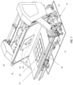
FIG. 1 illustrates a clamshell die press according to an embodiment of the present disclosure. -
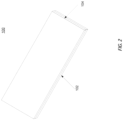
FIG. 2 illustrates a padding block according to an embodiment of the present disclosure. -
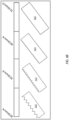
FIG. 3 illustrates some exemplary arrangements of padding blocks. -
FIG. 4A illustrates some blade profiles that may be used in steel rule die cut. -
FIG. 4B exemplary tooth profiles and padding layers with matching hardness measurements according to an embodiment of the present disclosure. -
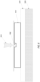
FIG. 5 shows a creasing matrix used in the soft cut system according to an embodiment of the present disclosure. -
FIG. 6 illustrates an exemplary process for using the soft cut system in die press according to an embodiment of the present disclosure. - The current die presses use steel blades having certain tooth profiles to cut through work pieces. During cutting, the steel blades are pressed with force (measured in tonnages) against a work piece. The downward force can cause steal blades cutting through the work piece until the blades strike against (i.e., contact with force) the working surface of the fixed platen. To make a clean cut, it is desirable for the steel blades to apply an even pressure on the work piece until the work piece is cut evenly and cleanly. By pressing the moving platen against the fixed platen, the steel blades compress the work piece until an explosion (clean cut) occurs. To create an even and level load so as to achieve the cut through, an operator needs to prepare a flat working surface on the fixed platen because the working surface can become uneven (due to knife wears) and the uneven working surface may cause unclean cuts at those uneven areas. The preparation process may take anywhere from 30 to 180 minutes or more of the operator's time.
- Additionally, the current steel-to-steel cut can generate high-pitch and high-decibel noise at the explosion. This noise associated with die cutting is a type of working hazard for the die press operator. Also, current die cutting requires the application of a high-tonnage force to compress the work piece against the working surface of the fixed platen. The generation of the high-tonnage force consumes a large amount of energy. Therefore, there is a need to improve the current die cutting.
- Instead of the hard steel-to-steel die cutting as currently used in clamshell die presses, embodiments of the present disclosure provide a soft die cutting system that includes a set of soft padding blocks. These padding blocks may be configured into a pad mounted on the top of the working surface of the fixed platen. Each padding block may include a steel backing and a padding layer bonded to the steel backing. The steel backing, when mounted, may be affixed to the working surface of the fixed platen using binding agents (e.g., a magnetic layer) while the padding layer faces the direction of the moving platen or the blades. One or more pieces of padding blocks may be placed on the working surface of the fixed platen to form a pad on top of the fixed platen. The padding blocks may be arranged in a variety of combinations to form the pads of different shapes, thus covering different areas on the working surface. Work pieces to be cut may be placed on the pad formed by the padding blocks to enable a soft cut of the work pieces.
- Since padding blocks may be easily rearranged into pads having different area coverages, the time required to provide the cutting surface on the fixed platen is significantly reduced, compared to the time traditionally spent on preparing the working surface of the fixed platen. Further, because the blades of the die cutter may cut through the work pieces into the soft padding layers of the padding blocks, the press load (or pressing force tonnage) needed for cutting various substrates may be significantly reduced. The deeper cuts into the soft padding layers can result in cleaner cuts (i.e., fewer angel hairs attached to the products). Further, because of the soft padding layer, the steel blades do not directly scratch the working surface of the fixed platen, the noise associated with the die cutting can be reduced significantly, thus improving the working environment for the die press operators.
-
FIG. 1 illustrates a clamshell diepress 10 according to an embodiment of the present disclosure. As shown inFIG. 1 , thedie press 10 may include aframe 12, afixed platen 14, and a movingplaten 16. Diepress 10 may be secured to the ground throughframe 12, and fixedplaten 14 may be securely mounted ontoframe 12. Fixedplaten 14 may be made of steel and may provide a substantially level working surface with respect to the ground. Movingplaten 16 may include afirst end 18 that is engaged with a track and a secondfree end 20 can be in an open position or a close position with respect to the working surface of fixedplaten 14. At the open position, thefree end 20 of the movingplaten 16 is away fromfixed platen 14, whereas at the close position, thefree end 20 of the movingplaten 16 is pushed to thefixed platen 14 to enable an inner surface of movingplaten 16 substantially parallel to the working surface of thefixed platen 14. While at the close position, there is a gap space between the working surface offixed platen 14 and the inner surface of movingplaten 16. In one embodiment, diepress 10 may be a regular clamshell press that has a small gap of approximately 2.54 cm and 3.81 cm (one to one and half inches). In another embodiment, diepress 10 may be a Widemouth™ die press that has an adjustable gap between 2.54 cm and 7.62 cm (one and three inches). - Moving
platen 16 may be transitioned by an operator between the open position and the close position via a track path using gears and arms. In one embodiment,tooling 22 may be installed on the inner surface (i.e., the surface of movingplaten 16 that faces the working surface of fixed platen 14) for die cutting.Tooling 22 may includesteel blades 24 andrubber ejections 26 that surround thesteel blades 24.Steel blades 24 may be installed on the inner surface of movingplaten 16 to create different cutting patterns. During die cutting,steel blades 24 may cut work pieces into products of different shapes, while therubber ejections 26 may help release the finished products from thesteel blades 24. - In one embodiment, instead of mounting work pieces directly onto the working surface of fixed
platen 14, asoft pad 28 may be mounted on the working surface of fixedplaten 14 to provide a soft cutting surface toblades 24.Pad 28 may be formed by mounting one or more padding blocks 28 on the working surface of fixedplaten 14. In one embodiment, padding blocks 28 used to formpad 28 may have substantially the same geometric contour shape. In another embodiment, padding blocks 28 used to formpad 28 may have different contour shapes. Different combinations of padding blocks 28 (of the same shape or different shapes) may producepad 28 covering different areas on the working surface of fixedplaten 14. -
FIG. 2 illustrates a padding block 100 according to an embodiment of the present disclosure. Padding block 100 can have different contour shapes. In one embodiment as shown inFIG. 2 , the edge contour of padding block 100 may be rectangular. In other embodiments, the edge contour of padding block 100 may be other geometric shapes including, for example, triangles, squares, and circles. - Padding block 100 may include two or more layers composed of different materials. In one embodiment, as shown in
FIG. 2 , padding block 100 may include a backing layer 102 and a padding layer 104. Backing layer 102 may be composed of hard metals such as steel. Padding layers 104 may be composed of softer materials such as, for example, Urethane, rubber, ultra-high-molecular-weight (UHMW) polyethylene, or other materials that have a hardness measurement in terms of Shore durometer ranging from 30 A to 85 D. The materials of the padding layer 104 are softer than the blades, and allow the blades cut into the padding layer 104. Padding layer 104 can be bonded to backing layer 102 by chemical reaction. For example, padding layer 104 may be bonded to steel backing layer 102 by using heat-activated adhesive chemical agents. Once bonded, padding layer 104 is secured to backing layer 102. - Different combinations of padding blocks 100 may form
pad 28 covering areas of different contour shapes.FIG. 3 illustrates some exemplary arrangements of padding blocks 100. These arrangements of padding blocks can form pads of different shapes. Because the padding blocks 100 can be conveniently mounted at different locations on the working surface of the fixedplaten 14, the time to prepare and make ready the cutting surface can be reduced significantly. The time to prepare the cutting surface now includes the time to mount and/or reposition the padding blocks but without the need to level the surface of the fixedplaten 14. Further, the impression force applied by thedie press 10 to padding blocks 28 may be experimented with (e.g., increasing incrementally) until satisfactory cuts on work pieces are achieved. This process to adjust the impression force typically takes no more than two minutes. Thus, the soft cut system may significantly reduce the time to start the operation ofdie press 10. - The steel backing layer 102 of padding blocks may be used to secure padding blocks 100 onto the fixed
platen 14. For example, magnetic force may be used to secure padding blocks 100 to the fixedplaten 14. As shown inFIG. 1 , in one embodiment, a thin, double-sidedmagnetic layer 30 may be used to provide the magnetic force to secure the metal backing layers of padding blocks to fixedplaten 14.Magnetic layer 30 may be mounted on the working surface of fixedplaten 14, and padding blocks 100 may be mounted on top ofmagnetic layer 30 so as to bindpad 28 formed by padding blocks 100 to the fixedplaten 14 with the magnetic force. In addition, metal backing layer 102 may also provide a backbone for the soft material of padding layer 104 to prevent distortion during die cut. In another embodiment, backing layer 102 may be composed of magnetized metal (e.g., magnetized steel). The magnetized backing layer 102 may be mounted onto a metal working surface of fixedplaten 14, secured by the magnetic force. - Padding layer 104 of padding blocks 100 may be composed of different types of materials that have a variety of hardness measurements. Thus, padding blocks having padding layers of different hardness measurements may be employed to form
pad 28. In one embodiment, the type (i.e., hardness of the padding layer) of padding blocks may be selected based on the tooth profiles of theblades 24 and/or the material of the work pieces being cut. The type of padding blocks 100 is selected to enable a match of the hardness of padding layer with the tooth profiles ofblades 24 so that the match may produce the optimal cutting results. - For example, in steel rule die cut, blades may be specified according to a tooth profile including certain geometrical properties of the blade.
FIG. 4A illustrates some blade profiles that may be used in steel rule die cut. As shown inFIG. 4A , atooth profile 400 may include atooth portion 402 and agullet portion 404. Thetooth portion 402 includes tooth tips that can cut into work pieces, and thegullet portion 404 includes the curved area at the base of the teeth. Thetooth profile 400 may be associated with certain geometrical properties that may determine how the blade cuts into work pieces. For example, the tooth profile may include atooth pitch 406 that measures the distance from the tip of one tooth to the tip of the next tooth, and agullet depth 408 that measures the distance between the tooth tip and the bottom point of the gullet. Further, tooth profile may include different contour shapes for the teeth and gullets of the blade. As shown inFIG. 4A , for example, the blade may include, but not limited to, radius teeth andradius gullets 410, pointed teeth and V-shapedgullets 412, and pointed teeth andradius gullets 414. All these properties associated withtooth profile 400 may be used as parameters that determine the hardness measurement of the padding layer that best matches the blade. - The geometrical properties of
tooth profile 400 may be used to determine the pad that best matches to the tooth profile. To prepare for die cuts, the tooth profile may be selected to provide the desired edge quality on the work pieces using the least cutting force. Then, the hardness of the padding layer may be selected to match the tooth profile of the blades being used.FIG. 4B shows exemplary tooth profiles and padding layers with matching hardness measurements according to an embodiment of the present disclosure. As shown inFIG. 4B , largetoothed profile 420 may be matched a padding layer composed of materials measured at approximately 30 Shore A; an intermediate-sizedtoothed profile 422 may be matched a padding layer composed of materials measured at approximately 70 Shore A; a small toothed profile 424 may be matched a padding layer composed of materials measured at approximately 90 Shore A; an almost flat-toothed profile 426 may be matched a padding layer composed of materials measured at approximately 75 Shore D. Thus, the types of padding blocks (i.e., the hardness measurement of the padding layer) can be selected based, in part, on the tooth profile of the blades. - In one embodiment,
pad 28 may be formed on the working surface of fixedplaten 14 using a combination of different types of padding blocks 100. This combination of different types of padding blocks may be particularly useful when blades having different profiles are installed on the inner surface of movingplaten 16 to cut work pieces. Thus, the types of padding blocks may be selected to match the blades used to cut particular regions of the work piece. - Because different types of padding layers may be employed to provide cutting surfaces of different hardness measurements with respect to different types of blades, the soft cut system of the present disclosure may broaden the range of work piece materials that can be cut and improve the quality of cuts compared to the current steel-to-steel die cut systems. The soft cut system allows a new range of work piece materials to be cut, including, for example, foam boards and structural paper panels. These materials were traditionally cut by the slow process of plotter tables rather than clamshell die presses. The soft cut system as described in this disclosure may improve the productivity (up to 60 times) over the traditional process using plotter tables.
- The interchangeable padding blocks 100 of the soft cut system can also reduce wears on the blades and allow blades of a wider range of tooth profiles to be used because the blades can now cut into the soft surface of the padding layers of the padding blocks. Because the blade cuts into a softer padding layer and does not scratch a cutting surface that is at least as hard as the blade, the wears to the blade is significantly reduced. As such, the useful lives of blades used in the context of the soft cut system can be prolonged, thus reducing the cost for die cut. Further, by cutting against the soft padding layer rather than scratching the hard cutting surface of the fixed platen, the blades do not generate the hazardous noise level while cutting work pieces. The soft cut system further allows for a shear cut motion. The shear cut requires less tonnage for cutting through. The soft cut system can control the depth of the tooth profile cutting into the padding layer to enable precision cuts.
- The soft cut system also allows die cutting of multiple layers of work pieces. To cut multiple layers of work pieces, die press may need to increase the tonnage of pressing force applied by the moving platen. The higher tonnage of pressing force may cause damage to the blades when they strike the hard surface of the fixed platen. Thus, the steel-to-steel die cut typically allows die cutting of only a single layer of work piece. In contrast, blades of the die press including the soft cut system as described in the present disclosure cut into the soft material of the padding layer, thus permitting the higher force used in multiple-layer die cutting. For example, the soft cut system can be used to cut up to ten layers of a graphic decal in one press cycle as opposed to only one layer per cycle. Thus, the soft cut system may significantly increase the productivity of clamshell die presses.
- In one embodiment, a creasing matrix may be mounted on top of the
pad 28. The creasing matrix is a hardware module including channels which a die tooling may press against to create creases on (rather than cutting through) the work pieces.FIG. 5 shows a creasingmatrix 500 used in conjunction with the soft cut system according to an embodiment of the present disclosure. Creasingmatrix 500 can be made of composition materials such as, for example, an extruded polymer or vulcanized fiberboard. As shown inFIG. 5 , creasingmatrix 500 may include achannel 502. A creasing tooling, such as ablunt tooling 504 may press against a work piece intochannel 502 to create creases in the work piece. In one embodiment, apad 506 may be bonded to a fixedplaten 508 of a die press using magnetic force, and creasingmatrix 500 may be adhesively attached on to the top surface ofpad 506. -
FIG. 6 illustrates anexemplary process 600 for using the soft cut system in die press according to an embodiment of the present disclosure. As discussed above, a die press may be a clamshell die press including a fixed platen and a moving platen. At 602, the material of a work piece to be cut may be determined. The material of the work piece may be cardboard, plastic sheet, corrugated board, foam board, structural paper panels etc. In addition to determining the material of the work piece, certain physical properties of the work piece, such as the thickness and dimensions of the work piece, can be determined. - At 604, in response to determining properties of the work piece, die cut blades of certain tooth profile may be selected based on these properties of the work piece. The tooth profile may be selected based on the material of the work piece and depth that needs to be cut.
- At 606, in response to determining properties of the work piece and selecting the die cut blades, the padding blocks may be selected to match the properties of the work piece and the tooth profile of the die cut blades. The padding blocks may be selected to enable an optimal match between the hardness of the padding layer and the tooth profile of the cutting blades.
- At 608, in response to selecting the padding blocks, the selected padding blocks may be secured to the fixed platen. In one embodiment, the selected padding blocks may be secured to the fixed platen using a magnetic layer (e.g., a double-sided magnetic mat) to enable the bonding of padding blocks to the fixed platen. In one embodiment, rather than covering the whole surface of the fixed platen, the pad including the selected padding blocks covers only portions of the whole surface. For example, the pad may cover certain areas that receive the cutting blades during the die cut. After installation of the pad on the fixed platen and installation of the tooling including the cut blades, an operator may start operating the die press to cut work pieces.
- The words "example" or "exemplary" are used herein to mean serving as an example, instance, or illustration. Any aspect or design described herein as "example' or "exemplary" is not necessarily to be construed as preferred or advantageous over other aspects or designs. Rather, use of the words "example" or "exemplary" is intended to present concepts in a concrete fashion. As used in this application, the term "or" is intended to mean an inclusive "or" rather than an exclusive "or". That is, unless specified otherwise, or clear from context, "X includes A or B" is intended to mean any of the natural inclusive permutations. That is, if X includes A; X includes B; or X includes both A and B, then "X includes A or B" is satisfied under any of the foregoing instances. In addition, the articles "a" and "an" as used in this application and the appended claims should generally be construed to mean "one or more" unless specified otherwise or clear from context to be directed to a singular form. Moreover, use of the term "an embodiment" or "an embodiment" or "an implementation" or "one implementation" throughout is not intended to mean the same embodiment or implementation unless described as such.
- Reference throughout this specification to "an embodiment" or "an embodiment" means that a particular feature, structure, or characteristic described in connection with the embodiment is included in at least an embodiment. Thus, the appearance of the phrases "in an embodiment" or "in an embodiment" in various places throughout this specification are not necessarily all referring to the same embodiment. In addition, the term "or" is intended to mean an inclusive "or" rather than an exclusive "or."
- It is to be understood that the above description is intended to be illustrative, and not restrictive. Many other implementations will be apparent to those of skill in the art upon reading and understanding the above description. The scope of the disclosure should, therefore, be determined with reference to the appended claims.
Claims (8)
- A pad set (28) comprising padding blocks (100) for reconfigurably mounting on a flat working surface of a clamshell die press device (1) to provide a cushion for die cutting, wherein the pad set (28) comprises:a first padding block (100) comprising a backing layer (102) and a first padding layer (104) that is bonded to the backing layer (102), wherein the backing layer is composed of a metal and the first padding layer (104) is composed of a first padding material having a first Shore value; anda second padding block (100) comprising a second backing layer (102) and a second padding layer that is bonded to the second backing layer, wherein the second backing layer is composed of the metal and the second padding layer (104) is composed of a second padding material having a second Shore value, wherein the first Shore value is different than the second Shore value, one of the first padding block or the second padding block is to be mounted on a working surface of the clamshell die press device, the first padding block is paired with a first cutting blade (24) having a first tooth profile, and the second padding block is paired with a second cutting blade (24) having a second tooth profile, and the first and second Shore values represent a respective hardness measurement of the corresponding first and second padding materials, wherein a padding block is selected based on a determination that a hardness parameter of padding material of its padding layer matches a tooth profile of a cutting blade (24) installed on the clamshell die press device (1).
- The pad set (28) of claim 1, wherein the tooth profile of the cutting blade (24) comprises parameters representing at least one of a tooth pitch, a gullet depth, a tooth contour shape, or a valley contour shape, and wherein the hardness parameter of the material of the padding layer (104) is determined to match the tooth profile of the cutting blade (24), and wherein the hardness parameter is selected based on a rule that hardness of the material of the padding layer (104) decreases responsive to increasing the gullet depth of the cutting blade (24).
- The pad set (28) of any of claims 1 and 2, the padding layer (104) comprises at least one of Urethane, rubber, or ultra-high-molecular-weight (UHMW) polyethylene.
- The pad set (28) of claim 3, wherein the sheet of metal of the backing layer (102) is magnetized steel, and wherein a padding block of the pad set (28) is bonded to the working surface of the die press device via magnetic force.
- The pad set (28) of claim 1, wherein the tooth profile of the cutting blade (24) is determined based on a material composition of a work piece being cut by the cutting blade (24).
- A clamshell die press device (1) comprising the pad (28) of claim 1, further comprising:a fixed platen comprising the flat working surface on which the one or more padding blocks (100) are reconfigurably mounted; anda moving platen installed thereon a cutting blade (24).
- A clamshell die press device (1) of claim 6, further comprising a double-sided magnetic layer mounted on the flat working surface of the fixed platen, wherein the padding block is secured, via magnetic force, to the double-sided magnetic layer that is secured, via magnetic force, to the working surface of the fixed platen.
- A method comprising:determining a material composition of a work piece to be machined on a die press device;selecting, based on the material composition of the work piece, a first tooth profile of a cutting blade (24) installed on the die press device;selecting a first padding block that comprises a first padding layer and a first backing layer that is bonded to the first padding layer, wherein the first padding layer is composed of a first padding material having a first Shore value wherein the first cutting blade is paired with the first tooth profile;mounting the first padding block on a flat working surface of the die press device;responsive to replacing the first cutting blade with a second cutting blade having a second tooth profile, selecting a second padding block that comprises a second padding layer and a second backing layer that is bonded to the second padding layer, wherein the second padding layer is composed of a second padding material having a second Shore value, wherein the second cutting blade is paired with the second tooth profile, and wherein the second Shore value is different than the first Shore value, and the second tooth profile is different than the first tooth profile; andmounting the second padding block on the flat working surface of the die press device.
Applications Claiming Priority (2)
| Application Number | Priority Date | Filing Date | Title |
|---|---|---|---|
| US201562265217P | 2015-12-09 | 2015-12-09 | |
| PCT/US2016/065753 WO2017100527A2 (en) | 2015-12-09 | 2016-12-09 | Apparatus and method for die cutting |
Publications (3)
| Publication Number | Publication Date |
|---|---|
| EP3386694A2 EP3386694A2 (en) | 2018-10-17 |
| EP3386694A4 EP3386694A4 (en) | 2019-07-31 |
| EP3386694B1 true EP3386694B1 (en) | 2025-07-09 |
Family
ID=59013590
Family Applications (1)
| Application Number | Title | Priority Date | Filing Date |
|---|---|---|---|
| EP16873893.8A Active EP3386694B1 (en) | 2015-12-09 | 2016-12-09 | Apparatus and method for die cutting |
Country Status (5)
| Country | Link |
|---|---|
| US (1) | US10864650B2 (en) |
| EP (1) | EP3386694B1 (en) |
| JP (1) | JP6884794B2 (en) |
| ES (1) | ES3046677T3 (en) |
| WO (1) | WO2017100527A2 (en) |
Families Citing this family (10)
| Publication number | Priority date | Publication date | Assignee | Title |
|---|---|---|---|---|
| US11584035B2 (en) * | 2015-12-09 | 2023-02-21 | Phoenix Partners, Llc | Apparatus and system for die press and cutting |
| CN108994963A (en) * | 2018-07-13 | 2018-12-14 | 芜湖若科自动化科技有限公司 | A kind of circular saw easy to use |
| CN110856951A (en) * | 2018-08-24 | 2020-03-03 | 张家港保税区美佳印刷有限公司 | Tool base is tailor with pressing tooth to printing |
| US11511451B2 (en) * | 2020-01-31 | 2022-11-29 | The Boeing Company | Automated method and system for trimming a multi-ply structure |
| CN112706509A (en) * | 2020-12-25 | 2021-04-27 | 苏州恒吴汽车零部件科技有限公司 | Air transfer printing forming mould |
| DE102021100374B3 (en) | 2021-01-12 | 2022-06-30 | Cito-System Gmbh | Punching device, in particular flatbed punching device, for punching flat material to be punched |
| US11958204B2 (en) * | 2021-06-04 | 2024-04-16 | I-Crafter LLC | Double-sided magnetic cutting deck |
| CN114311056B (en) * | 2021-12-24 | 2024-01-09 | 和爱电磁兼容科技(安徽)有限公司 | Shaping and cutting equipment for wave-absorbing material production |
| JP1779547S (en) * | 2024-01-24 | 2024-09-10 | Cutting plotter | |
| JP1777138S (en) * | 2024-01-24 | 2024-08-06 | Cutting plotter |
Family Cites Families (24)
| Publication number | Priority date | Publication date | Assignee | Title |
|---|---|---|---|---|
| US2912388A (en) | 1956-09-07 | 1959-11-10 | United Shoe Machinery Corp | Rubber-resin cutting pads and methods of mixing and milling rubber-resin compositions |
| US3237499A (en) * | 1964-07-17 | 1966-03-01 | Falls Engineering And Machine | Roller die press cutter apparatus with automatic roll lift |
| US3277764A (en) * | 1964-09-09 | 1966-10-11 | Edward V Hene | Apparatus for working corrugated board or the like |
| US3566736A (en) * | 1969-04-09 | 1971-03-02 | Johnson & Quin Inc | Segment cutter |
| US3626800A (en) | 1969-12-10 | 1971-12-14 | Usm Corp | Conductive cutting pad |
| US3782166A (en) * | 1972-06-09 | 1974-01-01 | L Whistler | Die set assembly and magnet means for releasably attaching dies therein |
| US3855892A (en) * | 1973-03-07 | 1974-12-24 | Cir Cut Corp | Cutting rule |
| CA1012993A (en) * | 1975-02-04 | 1977-06-28 | A.T.R. Equipment Industries Ltd. | Bag removing apparatus |
| US4275629A (en) * | 1979-07-25 | 1981-06-30 | Ball Corporation | Separator-cutter |
| JPS5882700A (en) | 1981-11-12 | 1983-05-18 | 藤倉ゴム工業株式会社 | Method and device for punching soft material |
| US5152204A (en) * | 1989-05-02 | 1992-10-06 | Jose Trevizo | Clam shell die cutter |
| EP0395816A3 (en) * | 1989-05-02 | 1991-10-02 | Sunclipse, Inc. | Die cutters |
| US5172622A (en) * | 1991-11-12 | 1992-12-22 | Lamcraft, Inc. | Quick change die cutter |
| US5778748A (en) * | 1996-04-22 | 1998-07-14 | School Systems Inc. | Offset crank activated paper die cutters |
| JPH10119000A (en) * | 1996-10-25 | 1998-05-12 | Sintokogio Ltd | Trimming type |
| US5916346A (en) | 1997-10-14 | 1999-06-29 | Robud | Die cutter blanket |
| ES2210849T3 (en) * | 1997-12-26 | 2004-07-01 | Nippon Tungsten Co., Ltd. | CUTTING ROLLER WITH MATRIX. |
| US6341557B1 (en) | 1999-09-09 | 2002-01-29 | Universal Engraving, Inc. | Non-ferrous/ferromatic laminated graphic arts impression dies and method of producing same |
| US6470779B1 (en) * | 2000-08-25 | 2002-10-29 | Richard J. Gannon | Card cutting apparatus |
| US20030145697A1 (en) | 2001-05-23 | 2003-08-07 | Hixon Natasha P. | Die cutting system, components thereof, and methods |
| JP2003340789A (en) | 2002-05-21 | 2003-12-02 | Fuji Photo Film Co Ltd | Punching device for tape |
| US20040112196A1 (en) * | 2002-07-18 | 2004-06-17 | Ellison Educational Equipment, Inc. | Interchangeable die press system and method |
| US6997092B2 (en) * | 2003-06-02 | 2006-02-14 | Chau Lih Rong Enterprise Co., Ltd. | Cutting apparatus |
| US7971513B2 (en) * | 2007-02-01 | 2011-07-05 | Lee Tack Plastic & Metal Manufactory, Ltd. | Paper punch die and paper punch with such a die |
-
2016
- 2016-12-09 US US16/060,198 patent/US10864650B2/en active Active
- 2016-12-09 WO PCT/US2016/065753 patent/WO2017100527A2/en not_active Ceased
- 2016-12-09 JP JP2018549765A patent/JP6884794B2/en active Active
- 2016-12-09 ES ES16873893T patent/ES3046677T3/en active Active
- 2016-12-09 EP EP16873893.8A patent/EP3386694B1/en active Active
Also Published As
| Publication number | Publication date |
|---|---|
| ES3046677T3 (en) | 2025-12-02 |
| JP6884794B2 (en) | 2021-06-09 |
| EP3386694A4 (en) | 2019-07-31 |
| WO2017100527A3 (en) | 2017-07-20 |
| US20180370064A1 (en) | 2018-12-27 |
| WO2017100527A2 (en) | 2017-06-15 |
| US10864650B2 (en) | 2020-12-15 |
| EP3386694A2 (en) | 2018-10-17 |
| JP2018537302A (en) | 2018-12-20 |
Similar Documents
| Publication | Publication Date | Title |
|---|---|---|
| US10864650B2 (en) | Apparatus and method for die cutting | |
| US11904493B2 (en) | Apparatus and system for die press and cutting | |
| EP1297931A3 (en) | Die cut roll | |
| CN207668590U (en) | A kind of hydraulic gate type guillotine shear | |
| CN2635307Y (en) | Bamboo material radial continuous grid splitting machine | |
| CN213107262U (en) | Die cutting device convenient to adjust blade | |
| CA2619496A1 (en) | Sharpener carried by the product table of a food slicer | |
| CN219114173U (en) | Paper pad stamping die processing device based on multipoint balance | |
| CN201168984Y (en) | Horizontal band saw cutting machine | |
| US7895926B2 (en) | Die cutting under vacuum through rollers | |
| GB2585591A (en) | A method of manufacturing a flexible, impact-resistant pad | |
| CN201268015Y (en) | Single side right-angle blade point engraving cutting die | |
| CN209986127U (en) | Locating seat for punching plate and manual punching machine comprising same | |
| KR20200013186A (en) | A Thomson device with rotary type magnetic cylinder equipped with flexible blade | |
| WO2002026455A2 (en) | Method and apparatus for moulding synthetic wood and product used therein | |
| CN211074879U (en) | Reverse side mould pressing cutting module | |
| CN216189853U (en) | Cutting machine with precise half-cutting and cutting functions | |
| KR102689178B1 (en) | driving device with cam type for thomson press device | |
| CN222697388U (en) | Convenient follow-up waste material clearance mechanism | |
| CN102233593A (en) | Device for cutting products on three sides | |
| CN219095361U (en) | Cutter structure of die cutting machine | |
| CN216505650U (en) | Cotton cross cutting spare of silica gel bubble | |
| EP1907176A1 (en) | Die cutting under vacuum through rollers | |
| CA2616620A1 (en) | Die cutting under vacuum through rollers | |
| CN207642125U (en) | A kind of segment difference mold |
Legal Events
| Date | Code | Title | Description |
|---|---|---|---|
| STAA | Information on the status of an ep patent application or granted ep patent |
Free format text: STATUS: THE INTERNATIONAL PUBLICATION HAS BEEN MADE |
|
| PUAI | Public reference made under article 153(3) epc to a published international application that has entered the european phase |
Free format text: ORIGINAL CODE: 0009012 |
|
| STAA | Information on the status of an ep patent application or granted ep patent |
Free format text: STATUS: REQUEST FOR EXAMINATION WAS MADE |
|
| 17P | Request for examination filed |
Effective date: 20180705 |
|
| AK | Designated contracting states |
Kind code of ref document: A2 Designated state(s): AL AT BE BG CH CY CZ DE DK EE ES FI FR GB GR HR HU IE IS IT LI LT LU LV MC MK MT NL NO PL PT RO RS SE SI SK SM TR |
|
| AX | Request for extension of the european patent |
Extension state: BA ME |
|
| DAV | Request for validation of the european patent (deleted) | ||
| DAX | Request for extension of the european patent (deleted) | ||
| A4 | Supplementary search report drawn up and despatched |
Effective date: 20190703 |
|
| RIC1 | Information provided on ipc code assigned before grant |
Ipc: B26D 7/20 20060101AFI20190627BHEP Ipc: B26D 1/00 20060101ALI20190627BHEP Ipc: B26D 1/30 20060101ALI20190627BHEP Ipc: B26F 1/40 20060101ALI20190627BHEP Ipc: B26F 1/44 20060101ALI20190627BHEP |
|
| STAA | Information on the status of an ep patent application or granted ep patent |
Free format text: STATUS: EXAMINATION IS IN PROGRESS |
|
| 17Q | First examination report despatched |
Effective date: 20220825 |
|
| GRAP | Despatch of communication of intention to grant a patent |
Free format text: ORIGINAL CODE: EPIDOSNIGR1 |
|
| STAA | Information on the status of an ep patent application or granted ep patent |
Free format text: STATUS: GRANT OF PATENT IS INTENDED |
|
| INTG | Intention to grant announced |
Effective date: 20250205 |
|
| GRAS | Grant fee paid |
Free format text: ORIGINAL CODE: EPIDOSNIGR3 |
|
| GRAA | (expected) grant |
Free format text: ORIGINAL CODE: 0009210 |
|
| STAA | Information on the status of an ep patent application or granted ep patent |
Free format text: STATUS: THE PATENT HAS BEEN GRANTED |
|
| AK | Designated contracting states |
Kind code of ref document: B1 Designated state(s): AL AT BE BG CH CY CZ DE DK EE ES FI FR GB GR HR HU IE IS IT LI LT LU LV MC MK MT NL NO PL PT RO RS SE SI SK SM TR |
|
| REG | Reference to a national code |
Ref country code: GB Ref legal event code: FG4D |
|
| REG | Reference to a national code |
Ref country code: CH Ref legal event code: EP |
|
| REG | Reference to a national code |
Ref country code: IE Ref legal event code: FG4D |
|
| REG | Reference to a national code |
Ref country code: DE Ref legal event code: R096 Ref document number: 602016092875 Country of ref document: DE |
|
| REG | Reference to a national code |
Ref country code: NL Ref legal event code: FP |
|
| REG | Reference to a national code |
Ref country code: ES Ref legal event code: FG2A Ref document number: 3046677 Country of ref document: ES Kind code of ref document: T3 Effective date: 20251202 |
|
| PG25 | Lapsed in a contracting state [announced via postgrant information from national office to epo] |
Ref country code: PT Free format text: LAPSE BECAUSE OF FAILURE TO SUBMIT A TRANSLATION OF THE DESCRIPTION OR TO PAY THE FEE WITHIN THE PRESCRIBED TIME-LIMIT Effective date: 20251110 |
|
| REG | Reference to a national code |
Ref country code: AT Ref legal event code: MK05 Ref document number: 1811444 Country of ref document: AT Kind code of ref document: T Effective date: 20250709 |
|
| PG25 | Lapsed in a contracting state [announced via postgrant information from national office to epo] |
Ref country code: IS Free format text: LAPSE BECAUSE OF FAILURE TO SUBMIT A TRANSLATION OF THE DESCRIPTION OR TO PAY THE FEE WITHIN THE PRESCRIBED TIME-LIMIT Effective date: 20251109 |
|
| PG25 | Lapsed in a contracting state [announced via postgrant information from national office to epo] |
Ref country code: NO Free format text: LAPSE BECAUSE OF FAILURE TO SUBMIT A TRANSLATION OF THE DESCRIPTION OR TO PAY THE FEE WITHIN THE PRESCRIBED TIME-LIMIT Effective date: 20251009 |
|
| REG | Reference to a national code |
Ref country code: LT Ref legal event code: MG9D |
|
| PG25 | Lapsed in a contracting state [announced via postgrant information from national office to epo] |
Ref country code: AT Free format text: LAPSE BECAUSE OF FAILURE TO SUBMIT A TRANSLATION OF THE DESCRIPTION OR TO PAY THE FEE WITHIN THE PRESCRIBED TIME-LIMIT Effective date: 20250709 |
|
| PG25 | Lapsed in a contracting state [announced via postgrant information from national office to epo] |
Ref country code: FI Free format text: LAPSE BECAUSE OF FAILURE TO SUBMIT A TRANSLATION OF THE DESCRIPTION OR TO PAY THE FEE WITHIN THE PRESCRIBED TIME-LIMIT Effective date: 20250709 |
|
| PG25 | Lapsed in a contracting state [announced via postgrant information from national office to epo] |
Ref country code: HR Free format text: LAPSE BECAUSE OF FAILURE TO SUBMIT A TRANSLATION OF THE DESCRIPTION OR TO PAY THE FEE WITHIN THE PRESCRIBED TIME-LIMIT Effective date: 20250709 |
|
| PG25 | Lapsed in a contracting state [announced via postgrant information from national office to epo] |
Ref country code: GR Free format text: LAPSE BECAUSE OF FAILURE TO SUBMIT A TRANSLATION OF THE DESCRIPTION OR TO PAY THE FEE WITHIN THE PRESCRIBED TIME-LIMIT Effective date: 20251010 |
|
| PG25 | Lapsed in a contracting state [announced via postgrant information from national office to epo] |
Ref country code: SE Free format text: LAPSE BECAUSE OF FAILURE TO SUBMIT A TRANSLATION OF THE DESCRIPTION OR TO PAY THE FEE WITHIN THE PRESCRIBED TIME-LIMIT Effective date: 20250709 |
|
| PG25 | Lapsed in a contracting state [announced via postgrant information from national office to epo] |
Ref country code: LV Free format text: LAPSE BECAUSE OF FAILURE TO SUBMIT A TRANSLATION OF THE DESCRIPTION OR TO PAY THE FEE WITHIN THE PRESCRIBED TIME-LIMIT Effective date: 20250709 |
|
| PG25 | Lapsed in a contracting state [announced via postgrant information from national office to epo] |
Ref country code: PL Free format text: LAPSE BECAUSE OF FAILURE TO SUBMIT A TRANSLATION OF THE DESCRIPTION OR TO PAY THE FEE WITHIN THE PRESCRIBED TIME-LIMIT Effective date: 20250709 Ref country code: BG Free format text: LAPSE BECAUSE OF FAILURE TO SUBMIT A TRANSLATION OF THE DESCRIPTION OR TO PAY THE FEE WITHIN THE PRESCRIBED TIME-LIMIT Effective date: 20250709 |
|
| PG25 | Lapsed in a contracting state [announced via postgrant information from national office to epo] |
Ref country code: RS Free format text: LAPSE BECAUSE OF FAILURE TO SUBMIT A TRANSLATION OF THE DESCRIPTION OR TO PAY THE FEE WITHIN THE PRESCRIBED TIME-LIMIT Effective date: 20251009 |
|
| PGFP | Annual fee paid to national office [announced via postgrant information from national office to epo] |
Ref country code: NL Payment date: 20260121 Year of fee payment: 10 |
|
| PG25 | Lapsed in a contracting state [announced via postgrant information from national office to epo] |
Ref country code: RO Free format text: LAPSE BECAUSE OF FAILURE TO SUBMIT A TRANSLATION OF THE DESCRIPTION OR TO PAY THE FEE WITHIN THE PRESCRIBED TIME-LIMIT Effective date: 20250709 |
|
| PG25 | Lapsed in a contracting state [announced via postgrant information from national office to epo] |
Ref country code: SM Free format text: LAPSE BECAUSE OF FAILURE TO SUBMIT A TRANSLATION OF THE DESCRIPTION OR TO PAY THE FEE WITHIN THE PRESCRIBED TIME-LIMIT Effective date: 20250709 |
|
| PGFP | Annual fee paid to national office [announced via postgrant information from national office to epo] |
Ref country code: GB Payment date: 20260122 Year of fee payment: 10 |
|
| PGFP | Annual fee paid to national office [announced via postgrant information from national office to epo] |
Ref country code: ES Payment date: 20260119 Year of fee payment: 10 |
|
| PG25 | Lapsed in a contracting state [announced via postgrant information from national office to epo] |
Ref country code: DK Free format text: LAPSE BECAUSE OF FAILURE TO SUBMIT A TRANSLATION OF THE DESCRIPTION OR TO PAY THE FEE WITHIN THE PRESCRIBED TIME-LIMIT Effective date: 20250709 |
|
| PGFP | Annual fee paid to national office [announced via postgrant information from national office to epo] |
Ref country code: DE Payment date: 20251231 Year of fee payment: 10 |
|
| PGFP | Annual fee paid to national office [announced via postgrant information from national office to epo] |
Ref country code: IT Payment date: 20260130 Year of fee payment: 10 |
|
| PGFP | Annual fee paid to national office [announced via postgrant information from national office to epo] |
Ref country code: FR Payment date: 20260116 Year of fee payment: 10 |
|
| PG25 | Lapsed in a contracting state [announced via postgrant information from national office to epo] |
Ref country code: CZ Free format text: LAPSE BECAUSE OF FAILURE TO SUBMIT A TRANSLATION OF THE DESCRIPTION OR TO PAY THE FEE WITHIN THE PRESCRIBED TIME-LIMIT Effective date: 20250709 |
|
| PG25 | Lapsed in a contracting state [announced via postgrant information from national office to epo] |
Ref country code: EE Free format text: LAPSE BECAUSE OF FAILURE TO SUBMIT A TRANSLATION OF THE DESCRIPTION OR TO PAY THE FEE WITHIN THE PRESCRIBED TIME-LIMIT Effective date: 20250709 Ref country code: SK Free format text: LAPSE BECAUSE OF FAILURE TO SUBMIT A TRANSLATION OF THE DESCRIPTION OR TO PAY THE FEE WITHIN THE PRESCRIBED TIME-LIMIT Effective date: 20250709 |
|
| PLBE | No opposition filed within time limit |
Free format text: ORIGINAL CODE: 0009261 |
|
| STAA | Information on the status of an ep patent application or granted ep patent |
Free format text: STATUS: NO OPPOSITION FILED WITHIN TIME LIMIT |