EP3386366B1 - Backing pad for use in a stain removal process - Google Patents
Backing pad for use in a stain removal process Download PDFInfo
- Publication number
- EP3386366B1 EP3386366B1 EP17793637.4A EP17793637A EP3386366B1 EP 3386366 B1 EP3386366 B1 EP 3386366B1 EP 17793637 A EP17793637 A EP 17793637A EP 3386366 B1 EP3386366 B1 EP 3386366B1
- Authority
- EP
- European Patent Office
- Prior art keywords
- backing pad
- layer
- fluid
- stain
- chemical
- Prior art date
- Legal status (The legal status is an assumption and is not a legal conclusion. Google has not performed a legal analysis and makes no representation as to the accuracy of the status listed.)
- Active
Links
Images









Classifications
-
- D—TEXTILES; PAPER
- D06—TREATMENT OF TEXTILES OR THE LIKE; LAUNDERING; FLEXIBLE MATERIALS NOT OTHERWISE PROVIDED FOR
- D06F—LAUNDERING, DRYING, IRONING, PRESSING OR FOLDING TEXTILE ARTICLES
- D06F43/00—Dry-cleaning apparatus or methods using volatile solvents
- D06F43/002—Spotting apparatus
-
- A—HUMAN NECESSITIES
- A47—FURNITURE; DOMESTIC ARTICLES OR APPLIANCES; COFFEE MILLS; SPICE MILLS; SUCTION CLEANERS IN GENERAL
- A47L—DOMESTIC WASHING OR CLEANING; SUCTION CLEANERS IN GENERAL
- A47L13/00—Implements for cleaning floors, carpets, furniture, walls, or wall coverings
- A47L13/10—Scrubbing; Scouring; Cleaning; Polishing
- A47L13/16—Cloths; Pads; Sponges
-
- A—HUMAN NECESSITIES
- A47—FURNITURE; DOMESTIC ARTICLES OR APPLIANCES; COFFEE MILLS; SPICE MILLS; SUCTION CLEANERS IN GENERAL
- A47L—DOMESTIC WASHING OR CLEANING; SUCTION CLEANERS IN GENERAL
- A47L13/00—Implements for cleaning floors, carpets, furniture, walls, or wall coverings
- A47L13/10—Scrubbing; Scouring; Cleaning; Polishing
- A47L13/26—Other cleaning devices with liquid supply arrangements
-
- A—HUMAN NECESSITIES
- A47—FURNITURE; DOMESTIC ARTICLES OR APPLIANCES; COFFEE MILLS; SPICE MILLS; SUCTION CLEANERS IN GENERAL
- A47L—DOMESTIC WASHING OR CLEANING; SUCTION CLEANERS IN GENERAL
- A47L25/00—Domestic cleaning devices not provided for in other groups of this subclass
- A47L25/08—Pads or the like for cleaning clothes
-
- B—PERFORMING OPERATIONS; TRANSPORTING
- B08—CLEANING
- B08B—CLEANING IN GENERAL; PREVENTION OF FOULING IN GENERAL
- B08B3/00—Cleaning by methods involving the use or presence of liquid or steam
- B08B3/04—Cleaning involving contact with liquid
- B08B3/08—Cleaning involving contact with liquid the liquid having chemical or dissolving effect
-
- C—CHEMISTRY; METALLURGY
- C11—ANIMAL OR VEGETABLE OILS, FATS, FATTY SUBSTANCES OR WAXES; FATTY ACIDS THEREFROM; DETERGENTS; CANDLES
- C11D—DETERGENT COMPOSITIONS; USE OF SINGLE SUBSTANCES AS DETERGENTS; SOAP OR SOAP-MAKING; RESIN SOAPS; RECOVERY OF GLYCEROL
- C11D17/00—Detergent materials or soaps characterised by their shape or physical properties
- C11D17/04—Detergent materials or soaps characterised by their shape or physical properties combined with or containing other objects
- C11D17/049—Cleaning or scouring pads; Wipes
-
- C—CHEMISTRY; METALLURGY
- C11—ANIMAL OR VEGETABLE OILS, FATS, FATTY SUBSTANCES OR WAXES; FATTY ACIDS THEREFROM; DETERGENTS; CANDLES
- C11D—DETERGENT COMPOSITIONS; USE OF SINGLE SUBSTANCES AS DETERGENTS; SOAP OR SOAP-MAKING; RESIN SOAPS; RECOVERY OF GLYCEROL
- C11D3/00—Other compounding ingredients of detergent compositions covered in group C11D1/00
- C11D3/0005—Other compounding ingredients characterised by their effect
- C11D3/0047—Other compounding ingredients characterised by their effect pH regulated compositions
-
- C—CHEMISTRY; METALLURGY
- C11—ANIMAL OR VEGETABLE OILS, FATS, FATTY SUBSTANCES OR WAXES; FATTY ACIDS THEREFROM; DETERGENTS; CANDLES
- C11D—DETERGENT COMPOSITIONS; USE OF SINGLE SUBSTANCES AS DETERGENTS; SOAP OR SOAP-MAKING; RESIN SOAPS; RECOVERY OF GLYCEROL
- C11D3/00—Other compounding ingredients of detergent compositions covered in group C11D1/00
- C11D3/02—Inorganic compounds ; Elemental compounds
- C11D3/12—Water-insoluble compounds
- C11D3/1233—Carbonates, e.g. calcite or dolomite
-
- C—CHEMISTRY; METALLURGY
- C11—ANIMAL OR VEGETABLE OILS, FATS, FATTY SUBSTANCES OR WAXES; FATTY ACIDS THEREFROM; DETERGENTS; CANDLES
- C11D—DETERGENT COMPOSITIONS; USE OF SINGLE SUBSTANCES AS DETERGENTS; SOAP OR SOAP-MAKING; RESIN SOAPS; RECOVERY OF GLYCEROL
- C11D3/00—Other compounding ingredients of detergent compositions covered in group C11D1/00
- C11D3/16—Organic compounds
- C11D3/20—Organic compounds containing oxygen
- C11D3/2075—Carboxylic acids-salts thereof
- C11D3/2086—Hydroxy carboxylic acids-salts thereof
-
- C—CHEMISTRY; METALLURGY
- C11—ANIMAL OR VEGETABLE OILS, FATS, FATTY SUBSTANCES OR WAXES; FATTY ACIDS THEREFROM; DETERGENTS; CANDLES
- C11D—DETERGENT COMPOSITIONS; USE OF SINGLE SUBSTANCES AS DETERGENTS; SOAP OR SOAP-MAKING; RESIN SOAPS; RECOVERY OF GLYCEROL
- C11D3/00—Other compounding ingredients of detergent compositions covered in group C11D1/00
- C11D3/16—Organic compounds
- C11D3/37—Polymers
- C11D3/3703—Macromolecular compounds obtained otherwise than by reactions only involving carbon-to-carbon unsaturated bonds
- C11D3/3707—Polyethers, e.g. polyalkyleneoxides
-
- C—CHEMISTRY; METALLURGY
- C11—ANIMAL OR VEGETABLE OILS, FATS, FATTY SUBSTANCES OR WAXES; FATTY ACIDS THEREFROM; DETERGENTS; CANDLES
- C11D—DETERGENT COMPOSITIONS; USE OF SINGLE SUBSTANCES AS DETERGENTS; SOAP OR SOAP-MAKING; RESIN SOAPS; RECOVERY OF GLYCEROL
- C11D3/00—Other compounding ingredients of detergent compositions covered in group C11D1/00
- C11D3/16—Organic compounds
- C11D3/37—Polymers
- C11D3/3746—Macromolecular compounds obtained by reactions only involving carbon-to-carbon unsaturated bonds
- C11D3/3753—Polyvinylalcohol; Ethers or esters thereof
-
- C—CHEMISTRY; METALLURGY
- C11—ANIMAL OR VEGETABLE OILS, FATS, FATTY SUBSTANCES OR WAXES; FATTY ACIDS THEREFROM; DETERGENTS; CANDLES
- C11D—DETERGENT COMPOSITIONS; USE OF SINGLE SUBSTANCES AS DETERGENTS; SOAP OR SOAP-MAKING; RESIN SOAPS; RECOVERY OF GLYCEROL
- C11D3/00—Other compounding ingredients of detergent compositions covered in group C11D1/00
- C11D3/16—Organic compounds
- C11D3/37—Polymers
- C11D3/3746—Macromolecular compounds obtained by reactions only involving carbon-to-carbon unsaturated bonds
- C11D3/3757—(Co)polymerised carboxylic acids, -anhydrides, -esters in solid and liquid compositions
- C11D3/3761—(Co)polymerised carboxylic acids, -anhydrides, -esters in solid and liquid compositions in solid compositions
-
- C—CHEMISTRY; METALLURGY
- C11—ANIMAL OR VEGETABLE OILS, FATS, FATTY SUBSTANCES OR WAXES; FATTY ACIDS THEREFROM; DETERGENTS; CANDLES
- C11D—DETERGENT COMPOSITIONS; USE OF SINGLE SUBSTANCES AS DETERGENTS; SOAP OR SOAP-MAKING; RESIN SOAPS; RECOVERY OF GLYCEROL
- C11D3/00—Other compounding ingredients of detergent compositions covered in group C11D1/00
- C11D3/16—Organic compounds
- C11D3/37—Polymers
- C11D3/3746—Macromolecular compounds obtained by reactions only involving carbon-to-carbon unsaturated bonds
- C11D3/3769—(Co)polymerised monomers containing nitrogen, e.g. carbonamides, nitriles or amines
-
- C—CHEMISTRY; METALLURGY
- C11—ANIMAL OR VEGETABLE OILS, FATS, FATTY SUBSTANCES OR WAXES; FATTY ACIDS THEREFROM; DETERGENTS; CANDLES
- C11D—DETERGENT COMPOSITIONS; USE OF SINGLE SUBSTANCES AS DETERGENTS; SOAP OR SOAP-MAKING; RESIN SOAPS; RECOVERY OF GLYCEROL
- C11D3/00—Other compounding ingredients of detergent compositions covered in group C11D1/00
- C11D3/39—Organic or inorganic per-compounds
- C11D3/3942—Inorganic per-compounds
-
- C—CHEMISTRY; METALLURGY
- C11—ANIMAL OR VEGETABLE OILS, FATS, FATTY SUBSTANCES OR WAXES; FATTY ACIDS THEREFROM; DETERGENTS; CANDLES
- C11D—DETERGENT COMPOSITIONS; USE OF SINGLE SUBSTANCES AS DETERGENTS; SOAP OR SOAP-MAKING; RESIN SOAPS; RECOVERY OF GLYCEROL
- C11D3/00—Other compounding ingredients of detergent compositions covered in group C11D1/00
- C11D3/395—Bleaching agents
- C11D3/3955—Organic bleaching agents
-
- C—CHEMISTRY; METALLURGY
- C11—ANIMAL OR VEGETABLE OILS, FATS, FATTY SUBSTANCES OR WAXES; FATTY ACIDS THEREFROM; DETERGENTS; CANDLES
- C11D—DETERGENT COMPOSITIONS; USE OF SINGLE SUBSTANCES AS DETERGENTS; SOAP OR SOAP-MAKING; RESIN SOAPS; RECOVERY OF GLYCEROL
- C11D3/00—Other compounding ingredients of detergent compositions covered in group C11D1/00
- C11D3/50—Perfumes
-
- C—CHEMISTRY; METALLURGY
- C11—ANIMAL OR VEGETABLE OILS, FATS, FATTY SUBSTANCES OR WAXES; FATTY ACIDS THEREFROM; DETERGENTS; CANDLES
- C11D—DETERGENT COMPOSITIONS; USE OF SINGLE SUBSTANCES AS DETERGENTS; SOAP OR SOAP-MAKING; RESIN SOAPS; RECOVERY OF GLYCEROL
- C11D2111/00—Cleaning compositions characterised by the objects to be cleaned; Cleaning compositions characterised by non-standard cleaning or washing processes
- C11D2111/10—Objects to be cleaned
- C11D2111/12—Soft surfaces, e.g. textile
Definitions
- the present invention relates to the field of stain removal, and in particular it relates to a backing pad used for fluid absorption in a stain removal process.
- Fabrics a class of material that is common used for garment and furnishing, can be easily contaminated by contaminants such as food, drinks and writing markers. The contamination typically results in unsightly stain spots that cannot be removed easily without washing the fabric. In some occurrences, the stains may even require extensive local pre-treatment prior to the laundry process. These are troublesome processes that can only take place when the whole fabric is due for washing.
- US2005/0130870A discloses cleaning a hard surface using a substrate impregnated with a dirt-attracting polycationic polymer which avoids dirt being redeposited on the cleaned surface.
- the substrate has a backing member that may be pervious or impervious to a cleaning composition.
- US2009/0188527A discloses an absorbent pad comprising a super-absorbent material with a liquid-resistant backing.
- the backing pad for use in a stain removal process comprises:
- the upper layer and the lower layer are stacked on each other.
- the upper layer comprises a superabsorbent.
- the present invention is based on the principle to improve stain removal processes using water or other fluids, by an increased fluid absorption in the backing pad.
- this invention is applicable to any processes involving fluid absorption and retaining, preventing fluid overflow and contamination with other objects.
- the superabsorbent is comprises a hydrophilic polymer.
- the superabsorbent is chosen from a copolymer or a polymer including at least one of a acrylonitrile based copolymer, an acrylamide based copolymer and a polyvinyl alcohol (PVA) based copolymer, poly acrylic acid, poly(vinyl alcohol), poly ethylene oxide (PEO).
- PVA polyvinyl alcohol
- PEO poly ethylene oxide
- the upper layer comprises any one of the following structure:
- the lower layer is made of a material comprising any one of plastic sheets, metal sheets, rubber sheets, wax paper, leather sheets and glass sheets.
- the upper layer of the backing pad comprises a pH indicator configured to indicate acidity or alkalinity of fluid getting in contact with the upper layer.
- the pH indicator is configured to indicate acidity or alkalinity by color via a change of color when the fluid getting in contact with the upper layer is acidic or basic.
- said pH indicator may exhibit color change as a function of pH value change. If the chemical cleaning agent used is acidic or alkaline, when it touches the backing pad, the color of the pad will change gradually as an indication of the presence of a cleaning agent. Hence, the color change is indicative for the start of the stain treatment and gives the user feedback that the stain is under removing reaction.
- the backing pad comprises at least two compartments that are isolated from each other by an impermeable barrier.
- the upper layer may comprise fragrance and/or perfume agents.
- each of said at least two compartments comprises a different fragrance and/or perfume agent.
- Different scents may also be used in different areas of the pad.
- the upper layer comprises a chemical neutralizer.
- the chemical neutralizer is selected among any one of the following:
- the backing pad is foldable.
- This feature contributes to save space.
- the backing pad further comprises an additional layer cooperating with any one of the upper layer and the lower layer.
- the additional layer provides mechanical stability and/or protection to the backing pad.
- the upper layer and/or the lower layer are made of a heat resistant material. Having a backing pad heat resistant is particularly important when irons, hair dryers or the heat from a stain removal device are used to accelerate the drying process. Otherwise the backing pad may change chemically or even start burning. This may contaminate the treated fabric with new stains or odors or even destroy said fabric.
- the backing pad according to the invention is especially suitable to be used together with a hand-held stain removal device which is able treat stain spots on garments locally without the need of washing the whole garment.
- Said hand-held stain remover device may have any combination of integrated functions of the following stages :
- the process involves various chemicals and chemical solutions (around 3 to 5mL of chemical cleaning solution to be used to remove a stain in 5cm diameter), and the absorption pad (also called backing pad) is put underneath the stained garment to prevent chemical contamination of operation tables and desks.
- the upper (i.e. top) layer of the pad should is fluid-absorptive and fluid-permeable. Materials can be hydrophilic polymer, cotton, synthetic fiber or any combination of these.
- the porous structure of the pad helps absorb the rinsing fluid and the microfibers are formed as capillaries to guide said fluid through. Superabsorbent is added to the pad to further enhance the fluid retaining capacity.
- the bottom layer of the absorption pad is non-permeable to water and chemical solutions may comprise polyester,polyethylene, or wax paper.
- water will be dosed on the stained treatment area to rinse off the stain residues and cleaning agents/chemicals. 10-100mL water should be used depending on the residue amount, which means that the absorption capacity of the backing pad per unit of area needs to be sufficient to avoid flooding.
- rinsing water left on the garment from stage 2 will be evaporated by heating to 100-200 °C depending on the stain, the chemical(s) used and the garment type to be treated. Taking the high temperature into consideration, the pad material for a drying stage should be heat resistant. Cellulose fibers like cotton fiber and wood pulp fluff are preferred materials.
- the backing pad according to the invention is meant to put underneath the stained garment to achieve better results and user experience for each of the above stages 1) 2) 3).
- the backing pad according to the invention may also be used in stain removal processes without said stain removal device.
- the backing pad may be used during treating a stained garment chemically with other appliances.
- the pad may also be used during rinsing using a conventional spray bottle. Put behind the garment the backing pad may then absorb excess fluid.
- drying wet garments using conventional irons or hair dryers, for instance, may be accelerated by the highly absorptive backing pad.
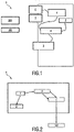
- Fig. 1 and Fig. 2 show two simplified schematic diagrams of a portable stain removal device 1 for removing a stain on a fabric 100. Actually they are substantially similar or same.
- the fluid (also called liquid) 200 for the rinsing process can be water, an aqueous solution, a neutralizer, a vapor or a powder. But in this embodiment, the fluid 200 for rinsing is water (steam and liquid water).
- the liquid 200 is stored in the liquid tank 2.
- a dispensing mechanism 3, for example a pump, is attached to the liquid tank 2 for transferring the water 200 out of the liquid tank 2 to a steam engine 4 which is configured to convert the liquid water 200 into steam 200.
- the dispensing mechanism 3 is activated by operating a rinsing pump trigger 5.
- the steam 200 provided by the steam engine 4 is released from the stain removal device 1 by means of an outlet 6.
- the optional drying method is heating with a heated plate 7.
- the steam venting face of the stain removal device 1 is then directed to the stained fabric 100 or a cleaning reagent 300 on the fabric 100.
- the cleaning reagent 300 may also be called chemical reagent, chemical, cleaning agent or stain removing material in
- Fig. 3 to Fig. 5 are respectively a perspective view, a front view and a side view of a portable device 1 for removing a stain on a fabric 100.
- a liquid tank 2 supplies water 200 to a dispensing mechanism 3, for example a pump.
- the pump 3 supplies water 200 to a steam engine 4.
- the steam engine 4 supplies steam 200 to the fabric 100 through an outlet 6, i.e. an opening which may be represented by a nozzle, on a heated plate 7. In the optional subsequent drying process, the plate 7 is also heated by the steam engine 4.
- the opening 6 on the heated plate 7 is sized to enable the outgoing steam 200 to have a certain velocity.
- This velocity is a function of the size of the opening and the steam rate.
- the optimal opening dimension is 6 mm in diameter. This combination gives a good steam rate and velocity to enhance the rinsing because the velocity creates a pressure difference between the treatment side and underside of the fabric 100. The pressure difference pushes the fluid 200 through the fabric 100.
- the relatively low steam rate also enables longer operation without the need for a large liquid tank 2.
- the steam rate can be between 5g/min and 150g/min.
- the diameter of the opening 6 can be between 3mm and 30mm.
- the steam 200 can be pure dry steam 200 (commonly transparent and hard to be envisaged by naked eyes) or wet steam 200 (commonly white color). It was observed that wet steam 200 (steam with droplets of water) produced better rinsing results but wetter fabric 100.
- Rinsing duration is dependent on the required quality of rinse. It was observed that rinsing duration should be at least 10 seconds with this defined opening size and steam rate. The rinse duration should be at least 3 seconds for such a device 1.
- the heated plate 7 may also be used for drying. During drying, the heated plate 7 should have a temperature between 60°C and 170°C.
- Fig. 6 and Fig. 7 are respectively a front view and a side view of a portable device 1 for removing a stain on a fabric 100.
- This embodiment consists of a heated plate 7, a liquid tank 2 for holding rinsing water, a dispensing mechanism 3, i.e. a rinsing pump 3, to supply water 200, a rinsing pump trigger 5, a brush 8 (optionally an electro-mechanical motor brush) and an optional temperature switch 10.
- the water tank 2 supplies water 200 for rinsing to the rinsing pump 3.
- the rinsing pump 3 supplies water 200 to an outlet 6 (rinse fluid outlet) beside the brush 8.
- fluid 200 is pumped out of the outlet 6 and onto the fabric 100 for the purpose of dilution or neutralization the residual chemical reagent.
- the brush 3 provides a mechanical means and a pressure means of helping the rinse fluid 200 pass through the fabric 100 and/or out of the fabric 100.
- the rinsing fluid dosing rate can be between 5g/min and 150g/min.
- the brush 8 can be mechanical operated or powered by an electric motor to have a speed between 10 and 500 revolutions per minute.
- the brush 8 is activated by operating the brush trigger 9.
- the rinse fluid 200 may also be a chemical neutralizer.
- the user may select to move on to the optional drying.
- the heated plate 7 is placed onto the rinsed fabric 100 to provide for localized drying, similar to the action of an electric iron. The process is completed upon drying of the fabric 100.
- the temperature switch 10 on the device enables two temperature settings. This is optional but could be beneficial for treating different fabric types. For instance, delicate fabrics 100 require lower temperature for drying, while normal fabrics 100 can withstand higher temperatures for faster drying.
- drying may be achieved through other means of providing heat or air movement, such as hot air, radiation, moving air or vacuum extraction.
- the portable fabric treatment device 1 has the function of rinsing and drying a portion of a fabric 100.
- the ability to only rinse and dry a targeted portion of a piece of fabric 100 enables this device 1 to do localized fabric treatment.
- this device 1 uses a fluid 200 for dilution and a pressure difference to extract waste and excess fluid 200.
- the device 1 also uses heat to further dry the fabric 100 after the rinsing process.
- the integration of these functions enables the user to use the fabric 100 immediately after the proposed optional one/two step(s) of fabric treatment.
- the main advantage is that the fabric 100 can continue to be in service prior to the next laundry cycle.
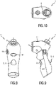
- Fig. 8, Fig. 9 and Fig. 10 are respectively a back (or front) view, a side view and a top view of a portable device 1 for removing a stain on a fabric.
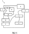
- Fig. 11 is another simplified module diagram of a portable device 1 for removing the stains on a fabric 100.
- This embodiment can consist of a heater 71, a heated plate 7, a chemical mixing tank 11, a chemical dosing trigger 12, a chemical dosing pump 13 and the required hose lines, a water tank 2 for holding rinsing water 200, a rinsing pump 3 to supply water 200, a rinsing pump trigger 5, a brush 8 (optionally electro-mechanical motor brush) and a temperature switch 10.
- This device 1 can be classified into the three main processes: stain removal, rinsing and drying. These processes can occur as the listed order.
- Fig. 12A to Fig. 12D is a schematic usage flow chart of the portable device 1 for removing a stain on a fabric 100.
- Fig. 12A shows the beginning of the stain removal process, wherein the chemical mixing tank 11 of the device 1 is preferably first heated, such that the chemical mixing tank 11 reaches a temperature of at least 65°C.
- the optimal temperature is between 80-90°C, though a temperature range of 65°C to 120°C is acceptable.
- Chemical 300 and water 200 are then added to the mixing tank 11 for dissolving the chemical 300 to form an aqueous solution.
- This chemical mixing tank 11 should be vented to prevent excessive gas build-up during the chemical solution preparation.
- this chemical solution can be prepared outside of the device 1 and added to the device as an aqueous solution.
- Fig. 12B shows the chemical treatment phase of the stain removal process.
- the chemical dosing trigger 12 activates the chemical dosing pump 13 to dispense the chemical 300 through an outlet 6 on the heated plate 7.
- the heated plate 7 should be placed on the surface of the stained fabric 100 to enable heating of the wetted fabric 100.
- the heat provided during the stain removing process is optional, but can greatly enhance stain removal result and speed by accelerating the chemical reaction. Alternatively, heat can be applied through other forms of heating, such as hot air, steam, microwave and exothermic reaction.
- Fig. 12C shows the rinsing phase of the stain removal process.
- the device 1 will enter the second phase of stain removal: rinsing.
- the brush head 8 of the device 1 is placed on the fabric 100 that is to be rinsed.
- the rinsing pump trigger 5 is then activated to activate the rinsing pump 3.
- Water 200 is pumped from the rinsing water tank 2, i.e. the liquid tank 2, through the pump 3 and out from an outlet 5 beside the brush 8. This process dilutes the chemical residue and washes the fabric 100 using water or aqueous solution.
- the motorised brush head 8 is activated to provide mechanical scrubbing action to push the waste water through and out of the fabric 100.
- the motorised brush 8 may be replaced by a sub-device that is able to provide mechanical action, such as a tapping motion, a forward-backward linear motion or a circular motion.
- a chemical neutraliser 200 may be applied to neutralise the residual chemical.
- Fig. 12D shows the drying phase of the stain removal process.
- the user moves on to the third process, which is the drying process.
- This process is optional and does not affect the stain removal process. However, it brings extra convenience to the user, such that the treated fabric 100 can be used almost immediately without waiting for the fabric 100 to dry.
- the temperature switch 10 of the device 1 is first activated to raise the temperature of the heated plate 7 to approximately 150°C. Alternatively, a temperature range of 100°C to 170°C is suitable for drying.
- the heated plate 7, which will be used for drying, should be cleaned prior to the drying process.
- the heated plate 7 is placed onto the rinsed fabric 100 to provide for localised drying, similar to the action of an electric iron.
- the process is completed upon drying of the fabric 100.
- drying may be achieved through other means of providing heat or air movement, such as hot air, radiation, moving air or vacuum extraction.
- the device 1 for stain removal can have the function of stain removal and/or rinsing. It may also have the function of drying.
- This device 1 uses heat to accelerate the stain removal process, then uses the means of chemical dilution and residue extraction to remove the chemical residues, so that the fabric 100 can continue to be in service prior to the next laundry cycle.
- the device 1 also uses heat to further drying the fabric 100 after the rinsing process. The integration of these functions enables the user to use the fabric 100 immediately after the proposed three steps of the stain removal process.
- the device 1 can further comprise a guide head 14.
- the guide head 14 comprises a back end interface 15 and a front end interface 16.
- the back end interface 15 receives the steam 200 produced from the main body of the device 1, the front end interface 16 gathers the steam 200 into a spout 17 facing the stains on the fabrics.
- the guide head 14 may comprise an insert slot 18 on the side of the guide head 14 near the back end interface 15.
- the insert slot 18 is equipped with an insert piece 600 inserted therein.
- the stain removal insert piece 600 contains stain removing material 300 inside and is applied to produce the chemical reagent 300 in the help of the steam 200 produced by the main body of the device 1 during the stain removing process.
- the stain removal insert piece 600 may also be called a holder 600 configured to contain a stain removal container 400.
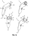
- Fig. 13 shows various schematic perspective views of a portable device 1 using a guide head 14 for removing the stains on a fabric 100.
- the stain removing material 300 can be bleach contents. Most of bleach contents 300 (Sodium percarbonate, TAED, DOBA, NOBS, etc) used in a laundry cleaning or dish washer products are in solid form (e.g. powder, granule). The bleach solid 300 requires to be dissolved in water in order to release H 2 O 2 or peroxy acid. H 2 O 2 or peroxy acid kills bacteria and removes stains on a substance like fabric, glass, or plastic by oxidizing the stain molecules from colored structure to colorless structure.
- bleach contents 300 Sodium percarbonate, TAED, DOBA, NOBS, etc
- H 2 O 2 or peroxy acid kills bacteria and removes stains on a substance like fabric, glass, or plastic by oxidizing the stain molecules from colored structure to colorless structure.
- Fig. 14, Fig. 15 and Fig. 16 are respectively chemical formations of H 2 O 2 from sodium percarbonate, peracetic acid from TAED, and perhydrolysis reaction of DOBA.
- the water dissolving rate of the bleach solid increases while the temperature increases. So H 2 O 2 or Peroxy acid will be released very fast while in contact with steam 200 or hot water 200.
- a stain removal container 400 which may be configured as a bag, a pad, a cartridge, a sachet or a disposable capsule containing bleach powder 300 to be directly attached to a stain removal device 1, which can produce heat, steam 200 and/or hot/cold water 200 and release bleach solution 300 instantly while steam 200 or water 200 passing through the bag 400.
- the bag material should be water permeable and can be made of high density paper, fabric, non-woven fabric, porous plastic, etc.
- the shape of the capsule bag 400 can be different. For example, circular, elliptic, triangular, rectangular, square, semi-circular or semi-elliptic. Dependent on the stain size and concentration the bag size and powder amount are variable as well.
- the container 400 takes any of the forms defined by a bag, a pad, a cartridge, a sachet, and a capsule.
- the bag may look like a "tea bag” with fluid-permeable external layer.
- It may include an optional frame 600, also called a holder in the following, which can be mounted onto the steam venting face (sometimes combined with the heated plate together) of the device 1, the frame 600 can also be mounted onto a steamer head.
- an optional frame 600 also called a holder in the following, which can be mounted onto the steam venting face (sometimes combined with the heated plate together) of the device 1, the frame 600 can also be mounted onto a steamer head.
- bleach solid/powder 300 embedded in a bag/satchel 400 with or without a support holder 600.
- an optional support holder 14 in somewhere of the disclosure it's called guide head
- the first working mechanism of it can be to mount this accessory (support holder 14 or guide head 14) to a steam generation device, a steamer, for example.
- a steam generation device a steamer
- the steam 200 passes through the "tea bag” 400 or capsule 400 while use.
- the bleach solids 300 inside the bag 400 or capsule 400 will dissolve by the condensation and carried out by steam 200.
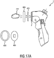
- Fig. 17A is a schematic side view of the stain removal device 1 as well as the chemical reagent bag 400 and the holder 600 of a portable device 1 using the holder 600 for removing the stains on a fabric 100.
- the bleach solid containing capsule/bag 400 is used with a hot water/steam generating stain remover device 1.
- the device 1 contains a small water tank 2 and releases hot water/steam 200 while treating the stain.
- the hot water/steam 200 passing through the bag 400 carries out the bleach solution 300.
- the bag 400 can be used as a separate part or the shape of the bag can be designed accordingly to fit onto the front frame of the device 1.
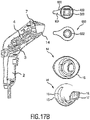
- the device's guide head 14 may comprise a back end interface 15 and a front end interface 16, the back end interface 15 receives the steam 200 produced from the main body of the device 1, the front end interface 16 gathers the steam 200 into a spout 17 facing the stains on a fabric 100.
- Fig. 17B are internal schematic side views of the stain removal device 1 as well as the chemical reagent bag 400 and the guide head 14 of a portable device 1 using a guide head 14 for removing the stains on a fabric 100.
- the holder 600 of the stain removal container may comprise a holding tab (also called a hand grip) 601 configured to make inserting the holder 600 into the stain removal device 1 easier.
- the holder 600 of the stain removal container 400 may comprise a rear 602 to reduce contact with the heated plate 7 when the holder 600 is attached to the device 1.
- Fig. 18A to Fig. 18F is a set of schematic usage flow charts of the portable device 1 with a guide 14 head and a chemical reagent bag 400 for removing the stains on a fabric 100.
- the guide head 14 in the present embodiment can also be replaced by a holder 600 to be attached to the steam venting face of the device 1 for holding a chemical bag 400.
- bleach contents 300 sodium percarbonate, TAED, DOBA, NOBS, etc.
- TAED TAED
- DOBA DOBA
- NOBS NOBS
- this embodiment discloses a disposable accessory 400 containing bleach powder 300 to be directly attached to a stain removal device 1 and to release bleach solution 300 instantly while usage accordingly.
- an integrated stain removal device 1 can be classified under three main processes.
- the tree main processes of stain treatment can be carried out.
- Fig. 18C shows the stain removing process.
- Cleaning reagents 300 are pre-filled in a cartridge, capsule, or a sachet 400 and are dispensed onto the stained area of the fabric, thanks to steam/water passing through the container/sachet 400.
- the device 1 also provides heat to the stain area 101 to accelerate the reacting, dissolving or covering rate.
- Heat sources include but are not limited to steam, conduction, IR heat and microwaves.
- the rinsing pump trigger 5 has to be pressed (possibly repeatedly).
- One of the usage situations shows examples of using a disposable cleaning powder sachet 400 or liquid film as cleaning agent 300, water and steam 200 carried by the device 1 pass through the sachet 400 to dissolve the powder 300 and carry the liquid/steam 200 onto the stain area 101.
- Fig. 18E shows the rinsing process.
- the rinse process can be achieved by either neutralization of the chemical or dilution of the chemical. For the best rinsing result, these chemical residues should be extracted from the fabric by an absorption means or by mechanical forces.
- the rinsing process is activated by pressing the rinsing pump trigger 5 (possibly repeatedly).
- Fig. 18D shows the detachment of the stain removal container 400 from the device 1.
- the sachet or cartridge 400 needs to be removed beforehand. This creates one more action step for the user to un-tighten and take off the sachet or cartridge 400 and find a place to put aside.
- Fig. 18F shows the drying process.
- Drying of the post-rinse fabric 100 relies on removal of the moisture on the fabric 100.
- the moisture can be evaporated through direct heating with a hot plate 7 ( ⁇ 100-170°C) or heated air 7( ⁇ 60-100°C).
- Fig. 19 is a schematic front view of a pathway selector 700 of the device 1.
- the main features may include(but not necessarily all of them are essential):
- this structure allows a selectable water pathway for stain treatment and rinsing in a stain removal device.
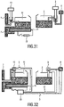
- Fig. 20 and Fig. 21 show two application situations for the pathway selector 700, also called selectable pathway piece in the following, of the device 1.
- the working face of the insert slot 18 i.e. selectable pathway piece 700
- the first part is for storing up the stain removing materials 300
- the second part is empty and may comprise a hole 705 for rinsing.
- the insert slot 18 is turnable, providing the first part 703 or the second part 704 facing the steam 200 produced from the main body of the device 1.
- the device 1 can provide two different functions by turning up or turning down, or turning left or turning right the hand grip 702 of the pathway selector in which one half is loaded with the bleach solid and the other half is empty.
- the working face of the insert piece 600 i.e. in this embodiment a pathway selector 700
- the first part is for storing up the stain removing materials
- the second part is empty.
- the pathway selector700 is turnable inside the insert slot 18, providing the first part 703 or the second part 704 facing the steam 200 produced from the main body of the device 1.
- Fig. 22 , Fig. 23 and Fig. 24 are other three application situations for the selectable pathway piece 700 of the device 1.
- the device 1 may further comprise a flap-flip piece 19 instead of a guide head 14 with an insert piece 600
- the flap-flip piece 19 comprises a frame 20 which is attached to the steam-venting face of the device 1 by a hinge 21.
- the flap-flip piece 19 may contain stain removing materials 300 inside, e.g. in form of a stain removal chemical bag 400, and is applied to produce the chemical reagent 300 with the help of the steam 200 produced by the main body of the device 1 during the stain removing process.
- the frame 20 may also comprise a hand grip 222 in order to prevent finger burn.
- the flap-flip piece 19 can be locked to the device to ensure that the stain removing materials get maximum contact to the steam or liquid 200 coming from the device 1.
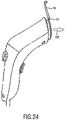
- Fig. 23 depicts the situation when the flap-flip piece 19 is locked to the device 1.
- Fig. 24 depicts a device 1 wherein the flap-flip piece 19 is unlocked and folded by means of the hinge 21 such that the stain removing materials 300 inside the frame 20 no longer face the steam or liquid 200 coming from the device.
- the device may further comprise an absorbent backing pad 800 intended to be placed underneath the fabric 100, as illustrated in Fig. 27D or Fig. 35 , under the stain area 101, during the stages of stain removing, rinsing and/or drying, in order to absorb the wet from the fabric 100, for example in order to dry the fabric 100.
- an absorbent backing pad 800 intended to be placed underneath the fabric 100, as illustrated in Fig. 27D or Fig. 35 , under the stain area 101, during the stages of stain removing, rinsing and/or drying, in order to absorb the wet from the fabric 100, for example in order to dry the fabric 100.
- Detailed information on the backing pad will be provided hereinafter along and illustrated via Fig. 27A to Fig. 27D , Fig. 25A to Fig. 25C , Fig. 26 , Fig. 28 , Fig. 35 and Fig. 36 .
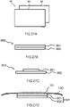
- Fig. 27A to Fig. 27D is a set of schematic views of a backing pad according to the present invention.
- the backing pad 800 is intended to be used in a stain removal process.
- the backing pad 800 comprises:
- the upper layer 801 and the lower layer 802 are stacked on each other.
- the upper layer 801 comprises a superabsorbent.
- the superabsorbent polymerizes to gel and retain the fluid getting into contact with the superabsorbent.
- absorbent polymers are hydrolyzed starch-acrylonitrile graft copolymer, a neutralized starch-acrylic acid graft copolymer, a saponified acrylic acid ester-vinyl acetate copolymer, a hydrolyzed acrylonitrile copolymer or acrylamide copolymer, a modified cross-linked polyvinyl alcohol, a neutralized self-cross-linking polyacrylic acid, a cross-linked polyacrylate salt, carboxylated cellulose, and a neutralized cross-linked isobutylene-maleic anhydride copolymer.
- Fig. 27A depicts an exploded view of the upper layer (801 and the lower layer 802 before assembly.
- Fig. 27B depicts a cross-section view of the upper layer 801 and the lower layer 802 stacked on each other.
- Fig. 27C depicts a cross-section view of the upper layer 801 and the lower layer 802 stacked on each other, where the areas of the upper layer 801 and the lower layer 802 are different.
- the area of the lower layer 802 is larger than the area of the upper layer 801.
- the side length of the upper layer (801) and the lower layer (802) is larger than 5cm if the target size of the stained area size is less than 5cm. More preferably the side length is larger than 10cm if the stain treatment area is separated from the rinsing and drying area.
- the upper layer and the lower layer are attached together by using adhesive material, such as glue.
- the backing pad can be applicable to all the stages (stain removing, rinsing and drying) that involve fluid absorption and retaining, in order to prevent fluid overflow and fluid contamination with other objects.
- This backing pad 800 is especially suitable to be used together with a hand-held stain removal device 1 which is able to locally treat stain spots on fabric 100, e.g. garment, without the need of washing the whole garment 100. This usage is illustrated in Fig. 35 .
- the hand-held stain removal device 1 has integrated functions of:
- the process involves various chemicals 300 and chemical solutions 300 (around 3 ⁇ 5ml of chemical cleaning solution 300 to be used to remove a stain of 5cm diameter), and the absorption backing pad 800 will be put underneath the stain area 101 of the garment 100 to prevent chemical contamination of operation tables and desks, or even users' skin if the backing pad is hold manually by user during treatment.
- the upper layer 801 should be very absorptive and permeable.
- the superabsorbent comprises a hydrophilic polymer.
- the superabsorbent is chosen from a copolymer or a polymer including at least one of a acrylonitrile based copolymer, an acrylamide based copolymer and a polyvinyl alcohol (PVA) based copolymer, poly acrylic acid, poly(vinyl alcohol), poly ethylene oxide (PEO).
- PVA polyvinyl alcohol
- Fig. 36A to Fig. 36C illustrate different embodiments of a backing pad according to the present invention implementing different fluid-absorptive upper layers.
- the upper layer 801 comprises any one of the following structure:
- the fluid-permeable fibrous material allows to maintain particles of the superabsorbent polymer which often are under an initial powder or granular form, in an alternate order.
- the fluid-permeable fibrous material corresponds to wood pulp or cotton linters.
- fluid-permeable fibrous material can stay as "one block” together with the superabsorbent polymer by using pressure and/or vacuum during assembly of those two materials.
- the bottom layer, i.e. lower layer, 802 of the absorption pad is non-permeable to water and chemical solutions.
- lower layer 802 is made of a material comprising any one of plastic sheets, metal sheets, rubber sheets, wax paper, leather sheets and glass sheets.
- water 200 will be dosed on the stain treatment area to rinse off the stain residues and cleaning agents/chemicals. 10-100ml water 200 should be used depending on the residue amount, which means that the absorption capacity per area of the upper layer 801 unit needs to be adapted accordingly to avoid flooding (i.e. fluid is no more absorbed by the upper layer).
- rinsing water 200 left on the garment from stage 2 will be evaporated by heating to 100-200 °C depending on the stain, chemical 300 used and garment type (i.e. fabric) under treatment.
- the upper layer 801 is made of a heat resistant material to avoid be damaged by the heat provided by the external device, and/or the lower layer 802 is made of a heat resistant material to avoid the support on which the garment and pad are placed be damaged.
- Cotton and cellulose are preferred materials.
- the absorption pad 800 also named backing pad, is meant to be put underneath the stain area 101 of the garment 100 to achieve better results for each stage.
- Fig. 25A to Fig. 25C are schematic exploded views of backing pads 800 according to the present invention comprising an additional layer 806.
- the additional layer 806 cooperates with any one of the upper layer 801 and the lower layer 802 for providing mechanical stability and/or protection to the backing pad 800.
- the additional layer 806 may be a permeable layer or an impermeable layer and may be added as e.g. a heat seal on top to provide physical strength and protection to any one of the upper layer 801 and the lower layer 802.
- Fig. 25A shows a backing pad 800 with the additional layer 806 arranged on top of the upper layer 801, and the lower layer 802 below the first 801.
- the additional layer 806 is fluid permeable.
- the additional layer 806 enhances the structural integrity and strength of the backing pad.
- Fig. 25B shows a backing pad 800, wherein the additional layer 806 is arranged in between the upper layer 801 and the lower layer 802.
- the additional layer 806 is fluid permeable or fluid impermeable.
- Fig. 25C shows a backing pad 800, wherein the additional layer 806 is arranged below the lower layer 802, and the upper layer 802 is arranged above the lower layer 802.
- the additional layer 806 is fluid permeable or fluid impermeable.
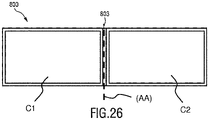
- Fig. 26 is a schematic front view of a backing pad according to the present invention comprising at least two compartments.
- the backing pad 800 can be divided into at least two isolated areas by putting a non-permeable barrier 803 in-between each compartment.
- the backing pad 800 is isolated into two compartments C1 and C2.
- a water proof barrier 803 is slotted in the middle.
- the backing pad 800 is foldable by having the two compartments being foldable around axis (AA).
- the compartments may be used for different treatment stages:
- the backing pad may also be divided in more than two compartments (not shown).
- each side of the pad 800 is estimated to be around 10 ⁇ 10 cm.
- the two (or more) compartments can be folded back to back in order to save space.
- Fig. 28A to 28C is a schematic front view of a backing pad according to the present invention embedded with one or more additives.
- One or more additives may be embedded into the backing pad 800, in particular into the upper layer in order to deliver better various results and user perception:
- alkaline pH indicator 805 which are colorless (invisible) when pH is neutral and colorful when pH is larger than 8-10 (alkaline) are selected in the following below table 1.
- Table 1 is a schematic table of different chemicals indicators: Table 1 Color pH value pH value Color Cresolphthalein colorless 8.2 9.8 purple Phenolphthalein colorless 8.3 10.0 purple-pink Thymolpbthalein colorless 9.3 10.5 blue
- Fig. 28B shows the backing pad 800 prior to stain treatment
- Fig. 28C shows the pad during and/or after stain treatment process. This illustrates that the pH indicator 805 has changed its color to reflect a change of the pH value.
- the backing pad would comprise a plurality of compartments, such as illustrated in Fig. 26 , for example a first compartment intended to be used during stain treatment, and a second compartment intended to be used during stain rinsing
- the pH indicator is preferably put into the upper layer of the second compartment only.
- the upper layer (801) comprises a chemical neutralizer 807 (not shown).
- a chemical neutralizer 807 can also be pre-embedded into the backing pad.
- the chemical neutralizer is selected among any one of the following:
- the backing pad would comprise a plurality of compartments, such as illustrated in Fig. 26 , for example a first compartment intended to be used during stain treatment, and a second compartment intended to be used during stain rinsing
- the chemical neutralizer is preferably put into the upper layer of the second compartment only.
- This embodiment to be described is about the way of treating a stain using a chemical medium 300 in combination with user's heating devices that could be commonly found at households such as a garment steamer or a garment iron.
- the combination of chemical 300 and heat can give good stain removing speed and result. With this way of stain removing, the stain spot can be removed effectively without the need for washing the whole piece of fabric 100.
- the stain removal chemical bag 400 which can be used in the present embodiment contains:
- Fig. 8 Please refer to Fig. 8 to Fig. 10 as some examples.
- power supply 22 can be connected to household supply while in operation (with power cord) or to an energy accumulator (cordless).
- the energy accumulator can be a storage battery or a capacitor based storage. In this cordless case, the device 1 can be charged at home but used at other places like office or can be brought out for traveling.
- Fig. 31 is a configuration diagram showing the power supply 22 applied to heat up the heater 71, which supplies heat to the chemical mixing tank 11 and the heated plate 7, while the chemical dosing pump 13, rinsing pump 3 and brush 8 are mechanical.
- Fig. 32 is a configuration diagram showing the power supply 22 applied to heat up the heater 71 to supply heat to the chemical mixing tank 11, and to provide electricity to the chemical dosing pump 13, also called chemical dispensing pump, and rotary brush 8.
- the power supply 22 can be used to heat up the chemical mixing tank 11 and the heated plate 7 (as shown in Fig. 31 ).
- the power supply 22 may as well provide electricity to other components integrated like the pumps 3 and 13and the brush 8 ( Fig. 32 ).
- the pumps and the brush may be triggered by the rinsing pump trigger 5, the chemical dosing trigger 12 and the brush trigger 9, respectively.
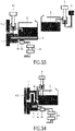
- Fig. 33 is a configuration diagram showing detachable power supply 23 (similar to a cordless iron) applied to heat up the heater 71 to supply heat to the chemical mixing tank 11 and the heated plate 7, while pump 3, pump 13 and the brush 8 are mechanical.
- Another way to achieve cordless execution but not using electrical power storage is to adopt a detachable power supply 22 to only store thermal energy in a short period (similar to cordless irons as shown in Fig. 33 ). In this case, as there is no electricity energy accumulator or battery, pumps 3 and 13 and brush 8 remain mechanically driven (manual).
- the process of supplying electricity to the heater is controlled by a control unit 24.
- the control unit 24 receives information from the temperature sensor 25 to control the heater 71.
- the bag 400 can be attached to a steam generating stain removal device 1 or a water dispensing stain removal device 1.
- a way to achieve a cordless option is similar as specified above.
- a steam generating stain removal device 1 comprising a steam chamber 26
- a detachable power supply 23 is a more practical way, as steam requires large amount of thermal energy.
- Fig. 34 is a configuration diagram showing a steam generating stain removal device 1 with a detachable power supply 23.
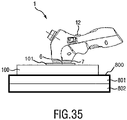
- Fig. 35 shows a backing pad used in a stain removal process with a stain removal device 1.
- the stain removal device 1 is used to treat the stain area 101 on the fabric 100.
- Below the fabric 100 there is placed the backing pad 800 for absorbing the wet from the stain treatment.
- the fluid permeable upper layer 801 faces towards the fabric 100, whereas the impermeable lower layer 802 faces away from the pad 800. This way, the pad may absorb the wet effectively and at the same time prevent contamination of operation desks or other fabric parts.
Landscapes
- Chemical & Material Sciences (AREA)
- Engineering & Computer Science (AREA)
- Chemical Kinetics & Catalysis (AREA)
- Organic Chemistry (AREA)
- Oil, Petroleum & Natural Gas (AREA)
- Wood Science & Technology (AREA)
- Life Sciences & Earth Sciences (AREA)
- Textile Engineering (AREA)
- Inorganic Chemistry (AREA)
- Health & Medical Sciences (AREA)
- Emergency Medicine (AREA)
- General Chemical & Material Sciences (AREA)
- Detergent Compositions (AREA)
- Accessory Of Washing/Drying Machine, Commercial Washing/Drying Machine, Other Washing/Drying Machine (AREA)
- Containers And Packaging Bodies Having A Special Means To Remove Contents (AREA)
Description
- The present invention relates to the field of stain removal, and in particular it relates to a backing pad used for fluid absorption in a stain removal process.
- Fabrics, a class of material that is common used for garment and furnishing, can be easily contaminated by contaminants such as food, drinks and writing markers. The contamination typically results in unsightly stain spots that cannot be removed easily without washing the fabric. In some occurrences, the stains may even require extensive local pre-treatment prior to the laundry process. These are troublesome processes that can only take place when the whole fabric is due for washing.
- However, the removal of stain spots immediately upon staining is usually preferred. Local removal of stain without the need of washing the whole garment is highly desired. This keeps the fabric looking clean even if the next laundry cycle is not immediate.
- There exists some known portable device able to locally remove stain in a quick manner, in particular by applying a chemical agent on the stain area, such as stain dissolving solutions, oxidation chemicals or detergents.
- In those known solutions, since the chemical agent is a fluid, there is a need to find a solution to prevent the user wearing the stained garment to get wet around the stain area, and limit the contact of the chemical with user's skin.
-
US2005/0130870A discloses cleaning a hard surface using a substrate impregnated with a dirt-attracting polycationic polymer which avoids dirt being redeposited on the cleaned surface. The substrate has a backing member that may be pervious or impervious to a cleaning composition. -
US2009/0188527A discloses an absorbent pad comprising a super-absorbent material with a liquid-resistant backing. - It is an object of the present invention to provide an improved backing pad that avoids or mitigates above-mentioned problems.
- The invention is defined by
independent claim 1. The dependent claims define advantageous embodiments. - To this end, the backing pad for use in a stain removal process according to the invention comprises:
- an upper layer being fluid-absorptive,
- a lower layer being fluid-impermeable,
- The upper layer and the lower layer are stacked on each other. The upper layer comprises a superabsorbent.
- The present invention is based on the principle to improve stain removal processes using water or other fluids, by an increased fluid absorption in the backing pad.
- In general, this invention is applicable to any processes involving fluid absorption and retaining, preventing fluid overflow and contamination with other objects.
- In stain removal processes on the run, stains have to be removed quickly, without any residues and the treated clothes have to be ready for use immediately after stain removal. In particular, this implies that the treated clothes have to be dry after the stain removal process. With a backing pad used to absorb the wet from cleaning, drying time can be shortened significantly. Furthermore, the fluid-impermeable lower layer prevents contamination of other materials with the absorbed fluid. Operation desks and other fabric parts of the treated clothes remain clean and dry.
- Preferably, the superabsorbent is comprises a hydrophilic polymer.
- Preferably, the superabsorbent is chosen from a copolymer or a polymer including at least one of a acrylonitrile based copolymer, an acrylamide based copolymer and a polyvinyl alcohol (PVA) based copolymer, poly acrylic acid, poly(vinyl alcohol), poly ethylene oxide (PEO). These substances provide for better water retaining and prevent fluid overflow in stain removal processes.
- Preferably, the upper layer comprises any one of the following structure:
- a) a single layer comprising a mixture of fluid-permeable fibrous material and superabsorbent polymer being stacked on the lower layer,
- b) a first layer comprising fluid-permeable fibrous material arranged adjacent to a second layer comprising a mixture of fluid-permeable fibrous material and superabsorbent polymer,
- c) a first layer comprising fluid-permeable fibrous material being stacked on the lower layer, a second layer comprising a mixture of fluid-permeable fibrous material and superabsorbent polymer being stacked on the first layer, and a third layer comprising fluid-permeable fibrous material being stacked on the second layer.
- Preferably, the lower layer is made of a material comprising any one of plastic sheets, metal sheets, rubber sheets, wax paper, leather sheets and glass sheets.
- All these materials prevent letting out the absorbed fluid on the lower side of the backing pad. This prevents contamination of working surfaces with the absorbed fluid.
- Preferably, the upper layer of the backing pad comprises a pH indicator configured to indicate acidity or alkalinity of fluid getting in contact with the upper layer.
- Preferably, the pH indicator is configured to indicate acidity or alkalinity by color via a change of color when the fluid getting in contact with the upper layer is acidic or basic. For example, said pH indicator may exhibit color change as a function of pH value change. If the chemical cleaning agent used is acidic or alkaline, when it touches the backing pad, the color of the pad will change gradually as an indication of the presence of a cleaning agent. Hence, the color change is indicative for the start of the stain treatment and gives the user feedback that the stain is under removing reaction.
- Preferably, the backing pad comprises at least two compartments that are isolated from each other by an impermeable barrier.
- Thereby, cross-contamination between the different compartments is prevented.
- Preferably, the upper layer may comprise fragrance and/or perfume agents.
- These additives create a better user perception during the stain removal process.
- In an embodiment of the backing pad, each of said at least two compartments comprises a different fragrance and/or perfume agent.
- Different scents may also be used in different areas of the pad.
- Preferably, the upper layer comprises a chemical neutralizer.
- Preferably, the chemical neutralizer is selected among any one of the following:
- weak acid-like citric acid and/or sodium citrate,
- - weak alkaline-like sodium carbonate and/or sodium bicarbonate,
- reducing agents.
- Since most cleaning agents are alkaline bases, weak acid like citric acid and sodium citrate are good choices to neutralize pH.
- Preferably, the backing pad is foldable.
- This feature contributes to save space.
- Preferably, the backing pad further comprises an additional layer cooperating with any one of the upper layer and the lower layer.
- The additional layer provides mechanical stability and/or protection to the backing pad.
- The upper layer and/or the lower layer are made of a heat resistant material. Having a backing pad heat resistant is particularly important when irons, hair dryers or the heat from a stain removal device are used to accelerate the drying process. Otherwise the backing pad may change chemically or even start burning. This may contaminate the treated fabric with new stains or odors or even destroy said fabric.
- These and other aspects of the invention will be apparent from and elucidated with reference to the embodiment(s) described hereinafter. In the following drawings
-
Fig. 1 is a simplified module diagram of a portable device for removing the stains on the fabrics according to an illustrative example which is not according to the claimed invention; -
Fig. 2 is another simplified module diagram of a portable device for removing the stains on the fabrics according to an illustrative example which is not according to the claimed invention; -
Fig. 3, Fig. 4 and Fig. 5 are respectively a perspective view, a front view and a side view of a portable device for removing the stains on the fabrics according to an illustrative example which is not according to the claimed invention; -
Fig. 6 and Fig. 7 are respectively a front view and a side view of a portable device for removing the stains on the fabrics according to an illustrative example which is not according to the claimed invention; -
Fig. 8, Fig. 9 and Fig. 10 are respectively a back view, a side view and a top view of a portable device for removing the stains on the fabrics according to an illustrative example which is not according to the claimed invention; -
Fig. 11 is another simplified module diagram of a portable device for removing the stains on the fabrics according to an illustrative example which is not according to the claimed invention; -
Fig. 12A to Fig. 12D is a set of schematic usage flow charts of the portable device for removing the stains on the fabrics according to an illustrative example which is not according to the claimed invention; -
Fig. 13 are various schematic perspective views of a portable device using guide head for removing the stains on the fabrics according to an illustrative example which is not according to the claimed invention; -
Fig. 14 shows the chemical formation of H2O2 from sodium percarbonate, -
Fig. 15 shows the chemical formation of peroxy acid from TAED, -
Fig. 16 shows the chemical formation of peroxy acid from DOBA, -
Fig. 17A is a schematic side view of the stain removal device as well as the chemical reagent bag and the holder of a portable device using holder for removing the stains on the fabrics according to an illustrative example which is not according to the claimed invention; -
Fig. 17B are internal schematic side view of the stain removal device as well as the chemical reagent bag and the guide head of a portable device using guide head for removing the stains on the fabrics according to an illustrative example which is not according to the claimed invention; -
Fig. 18A to Fig. 18F is a set of schematic usage flow charts of the portable device with guide head and chemical reagent bag for removing the stains on the fabrics according to an illustrative example which is not according to the claimed invention; -
Fig. 19 is a schematic front view of a selectable pathway piece of the device according to an illustrative example which is not according to the claimed invention; -
Fig. 20 andFig. 21 are two application situations for the selectable pathway piece of the device according to an illustrative example which is not according to the claimed invention; -
Fig. 22 ,Fig. 23 andFig. 24 are other three application situations for the selectable pathway piece of the device according to an illustrative example which is not according to the claimed invention; -
Fig. 25A to Fig. 25C are schematic exploded views of backing pads according to the present invention comprising an additional layer; -
Fig. 26 is a schematic front view of a backing pad according to the present invention comprising at least two compartments; -
Fig. 27A to Fig. 27D is a set of schematic views of a backing pad according to the present invention; -
Fig. 28A to Fig. 28C is a set of schematic front view of a backing pad according to the present invention embedded with one or more additives; -
Fig. 31 is a configuration diagram showing the power supply applied to heat up the chemical mixing tank and the heated plate, whilepump 1, pump 2 and brush are mechanical according to an illustrative example which is not according to the claimed invention; -
Fig. 32 is a configuration diagram showing the power supply applied to heat up the chemical mixing tank and provided electricity to the chemical dispensing pump and rotary brush according to an illustrative example which is not according to the claimed invention; -
Fig. 33 is a configuration diagram showing the detachable power supply similar as cordless iron applied to heat up the chemical mixing tank and the heated plate, whilepump 1, pump 2 and brush are mechanical according to an illustrative example which is not according to the claimed invention; -
Fig. 34 is a configuration diagram showing a steam generating stain remover device with a detachable power supply according to an illustrative example which is not according to the claimed invention. -
Fig. 35 shows a backing pad used in a stain removal process with a stain removal device, -
Fig. 36A to Fig. 36C illustrate different embodiments of a backing pad according to the present invention implementing different fluid-absorptive upper layers. - The backing pad according to the invention is especially suitable to be used together with a hand-held stain removal device which is able treat stain spots on garments locally without the need of washing the whole garment. Said hand-held stain remover device may have any combination of integrated functions of the following stages :
- 1) stain treatment by water/steam or by chemical cleaning, or by water/steam plus chemical cleaning;
- 2) rinsing off stain residues and chemical residues;
- 3) evaporating water from the treated area of the garment.
- At
stage 1, the process involves various chemicals and chemical solutions (around 3 to 5mL of chemical cleaning solution to be used to remove a stain in 5cm diameter), and the absorption pad (also called backing pad) is put underneath the stained garment to prevent chemical contamination of operation tables and desks. In order to avoid the solution used to expand, the upper (i.e. top) layer of the pad should is fluid-absorptive and fluid-permeable. Materials can be hydrophilic polymer, cotton, synthetic fiber or any combination of these. The porous structure of the pad helps absorb the rinsing fluid and the microfibers are formed as capillaries to guide said fluid through. Superabsorbent is added to the pad to further enhance the fluid retaining capacity. On the other hand, the bottom layer of the absorption pad is non-permeable to water and chemical solutions may comprise polyester,polyethylene, or wax paper. - At
stage 2, water will be dosed on the stained treatment area to rinse off the stain residues and cleaning agents/chemicals. 10-100mL water should be used depending on the residue amount, which means that the absorption capacity of the backing pad per unit of area needs to be sufficient to avoid flooding. - At
stage 3, rinsing water left on the garment fromstage 2 will be evaporated by heating to 100-200 °C depending on the stain, the chemical(s) used and the garment type to be treated. Taking the high temperature into consideration, the pad material for a drying stage should be heat resistant. Cellulose fibers like cotton fiber and wood pulp fluff are preferred materials. - The backing pad according to the invention is meant to put underneath the stained garment to achieve better results and user experience for each of the above stages 1) 2) 3).
- Note that the backing pad according to the invention may also be used in stain removal processes without said stain removal device. For example, the backing pad may be used during treating a stained garment chemically with other appliances. The pad may also be used during rinsing using a conventional spray bottle. Put behind the garment the backing pad may then absorb excess fluid. Besides, drying wet garments using conventional irons or hair dryers, for instance, may be accelerated by the highly absorptive backing pad.
-
Fig. 1 and Fig. 2 show two simplified schematic diagrams of a portablestain removal device 1 for removing a stain on afabric 100. Actually they are substantially similar or same. - The fluid (also called liquid) 200 for the rinsing process can be water, an aqueous solution, a neutralizer, a vapor or a powder. But in this embodiment, the
fluid 200 for rinsing is water (steam and liquid water). In this embodiment, the liquid 200 is stored in theliquid tank 2. Adispensing mechanism 3, for example a pump, is attached to theliquid tank 2 for transferring thewater 200 out of theliquid tank 2 to asteam engine 4 which is configured to convert theliquid water 200 intosteam 200. Thedispensing mechanism 3 is activated by operating a rinsingpump trigger 5. Thesteam 200 provided by thesteam engine 4 is released from thestain removal device 1 by means of anoutlet 6. The optional drying method is heating with aheated plate 7. The steam venting face of thestain removal device 1 is then directed to thestained fabric 100 or acleaning reagent 300 on thefabric 100. The cleaningreagent 300 may also be called chemical reagent, chemical, cleaning agent or stain removing material in the following. -
Fig. 3 to Fig. 5 are respectively a perspective view, a front view and a side view of aportable device 1 for removing a stain on afabric 100. Aliquid tank 2 supplieswater 200 to adispensing mechanism 3, for example a pump. Thepump 3supplies water 200 to asteam engine 4. Thesteam engine 4 supplies steam 200 to thefabric 100 through anoutlet 6, i.e. an opening which may be represented by a nozzle, on aheated plate 7. In the optional subsequent drying process, theplate 7 is also heated by thesteam engine 4. - The
opening 6 on theheated plate 7 is sized to enable theoutgoing steam 200 to have a certain velocity. This velocity is a function of the size of the opening and the steam rate. For a steam rate of 25g/min, the optimal opening dimension is 6 mm in diameter. This combination gives a good steam rate and velocity to enhance the rinsing because the velocity creates a pressure difference between the treatment side and underside of thefabric 100. The pressure difference pushes the fluid 200 through thefabric 100. The relatively low steam rate also enables longer operation without the need for alarge liquid tank 2. - Optionally, the steam rate can be between 5g/min and 150g/min. The diameter of the
opening 6 can be between 3mm and 30mm. Thesteam 200 can be pure dry steam 200 (commonly transparent and hard to be envisaged by naked eyes) or wet steam 200 (commonly white color). It was observed that wet steam 200 (steam with droplets of water) produced better rinsing results butwetter fabric 100. - Rinsing duration is dependent on the required quality of rinse. It was observed that rinsing duration should be at least 10 seconds with this defined opening size and steam rate. The rinse duration should be at least 3 seconds for such a
device 1. - Optionally, after the rinsing process, the
heated plate 7 may also be used for drying. During drying, theheated plate 7 should have a temperature between 60°C and 170°C. -
Fig. 6 and Fig. 7 are respectively a front view and a side view of aportable device 1 for removing a stain on afabric 100. This embodiment consists of aheated plate 7, aliquid tank 2 for holding rinsing water, adispensing mechanism 3, i.e. a rinsingpump 3, to supplywater 200, a rinsingpump trigger 5,
a brush 8 (optionally an electro-mechanical motor brush) and anoptional temperature switch 10. - The
water tank 2 supplieswater 200 for rinsing to therinsing pump 3. The rinsingpump 3supplies water 200 to an outlet 6 (rinse fluid outlet) beside thebrush 8. During rinsing,fluid 200 is pumped out of theoutlet 6 and onto thefabric 100 for the purpose of dilution or neutralization the residual chemical reagent. Thebrush 3 provides a mechanical means and a pressure means of helping the rinse fluid 200 pass through thefabric 100 and/or out of thefabric 100. The rinsing fluid dosing rate can be between 5g/min and 150g/min. Thebrush 8 can be mechanical operated or powered by an electric motor to have a speed between 10 and 500 revolutions per minute. Thebrush 8 is activated by operating the brush trigger 9. The rinsefluid 200 may also be a chemical neutralizer. - When rinsing is completed, the user may select to move on to the optional drying. The
heated plate 7 is placed onto the rinsedfabric 100 to provide for localized drying, similar to the action of an electric iron. The process is completed upon drying of thefabric 100. - The
temperature switch 10 on the device enables two temperature settings. This is optional but could be beneficial for treating different fabric types. For instance,delicate fabrics 100 require lower temperature for drying, whilenormal fabrics 100 can withstand higher temperatures for faster drying. - Alternatively, drying may be achieved through other means of providing heat or air movement, such as hot air, radiation, moving air or vacuum extraction.
- So for these two above-mentioned embodiments, they describe a
portable device 1 for removing a stain on afabric 100. It has the characteristics and/or technical benefits as follows: - 1. The
portable device 1 is capable of rinsing and drying a targeted area of afabric 100, where rinsing is done through the application of afluid 200. The fluid 200 can be an aqueous solution, a neutralizer, a vapor or a powder. Drying is conducted by applying one or more of heat, fluid motion and absorbent material. - 2. The transmission of the fluid 200 from one side of the
fabric 100 to the other side during the rinsing may be aided by a device or means of applying pressure or force onto the fluid 200 orfabric 100, such as apump 3, abrush 8 or velocity of afluid 200. - 3. In this
device 1, heat in the drying process can be provided through direct contact of thetarget fabric 100 with aheated plate 7. Optionally, the heat may also be provided through radiation or hot air. - 4. In this
device 1, the rinsing process can be conducted through the addition ofwater 200 to dilute thechemical 300, followed by abrush 8 which removes excess water.Heated water 200 has better rinsing results. Optionally, the neutralization/dilution may be achieved by using a chemical neutralizer or another dilution medium. The process of post-dilution water extraction is optional, but it greatly enhances the rinsing effect. The post-dilution water extraction may also be achieved through other mechanical means, such as a tapping motion, rubbing motion,high velocity steam 200 and so on. - 5. In this
device 1, drying is achieved through heating of the post-rinse area with theheated plate 7 at elevated temperature in the range of 60-170°C. Optionally, hot air of over 60°C may also be used for drying. - In conclusion, the portable
fabric treatment device 1 has the function of rinsing and drying a portion of afabric 100. The ability to only rinse and dry a targeted portion of a piece offabric 100 enables thisdevice 1 to do localized fabric treatment. For the rinsing process, thisdevice 1 uses afluid 200 for dilution and a pressure difference to extract waste andexcess fluid 200. Thedevice 1 also uses heat to further dry thefabric 100 after the rinsing process. The integration of these functions enables the user to use thefabric 100 immediately after the proposed optional one/two step(s) of fabric treatment. The main advantage is that thefabric 100 can continue to be in service prior to the next laundry cycle. - As for the implementation of integrating all the three potential processes in a
stain removing device 1, please see the content as follows. -
Fig. 8, Fig. 9 and Fig. 10 are respectively a back (or front) view, a side view and a top view of aportable device 1 for removing a stain on a fabric. -
Fig. 11 is another simplified module diagram of aportable device 1 for removing the stains on afabric 100. - This embodiment can consist of a
heater 71, aheated plate 7, achemical mixing tank 11, achemical dosing trigger 12, achemical dosing pump 13 and the required hose lines, awater tank 2 for holdingrinsing water 200, a rinsingpump 3 to supplywater 200, a rinsingpump trigger 5, a brush 8 (optionally electro-mechanical motor brush) and atemperature switch 10. - The usage of this
device 1 can be classified into the three main processes: stain removal, rinsing and drying. These processes can occur as the listed order. -
Fig. 12A to Fig. 12D is a schematic usage flow chart of theportable device 1 for removing a stain on afabric 100. -
Fig. 12A shows the beginning of the stain removal process, wherein thechemical mixing tank 11 of thedevice 1 is preferably first heated, such that thechemical mixing tank 11 reaches a temperature of at least 65°C. The optimal temperature is between 80-90°C, though a temperature range of 65°C to 120°C is acceptable.Chemical 300 andwater 200 are then added to themixing tank 11 for dissolving the chemical 300 to form an aqueous solution. Thischemical mixing tank 11 should be vented to prevent excessive gas build-up during the chemical solution preparation. Alternatively, this chemical solution can be prepared outside of thedevice 1 and added to the device as an aqueous solution. -
Fig. 12B shows the chemical treatment phase of the stain removal process. When thechemical 300 has dissolved, it is dosed onto thestained fabric 100 by activating thechemical dosing trigger 12. Thechemical dosing trigger 12 activates thechemical dosing pump 13 to dispense the chemical 300 through anoutlet 6 on theheated plate 7. As thehot chemical 300 is being dispensed, theheated plate 7 should be placed on the surface of thestained fabric 100 to enable heating of the wettedfabric 100. The heat provided during the stain removing process is optional, but can greatly enhance stain removal result and speed by accelerating the chemical reaction. Alternatively, heat can be applied through other forms of heating, such as hot air, steam, microwave and exothermic reaction. -
Fig. 12C shows the rinsing phase of the stain removal process. Once the stain visibility has been reduced to a level that is acceptable by the user, thedevice 1 will enter the second phase of stain removal: rinsing. In the rinsing phase, thebrush head 8 of thedevice 1 is placed on thefabric 100 that is to be rinsed. The rinsingpump trigger 5 is then activated to activate therinsing pump 3.Water 200 is pumped from the rinsingwater tank 2, i.e. theliquid tank 2, through thepump 3 and out from anoutlet 5 beside thebrush 8. This process dilutes the chemical residue and washes thefabric 100 using water or aqueous solution. At the same time, the motorisedbrush head 8 is activated to provide mechanical scrubbing action to push the waste water through and out of thefabric 100. Alternatively, themotorised brush 8 may be replaced by a sub-device that is able to provide mechanical action, such as a tapping motion, a forward-backward linear motion or a circular motion. Alternatively, achemical neutraliser 200 may be applied to neutralise the residual chemical. -
Fig. 12D shows the drying phase of the stain removal process. When rinsing is completed, the user moves on to the third process, which is the drying process. This process is optional and does not affect the stain removal process. However, it brings extra convenience to the user, such that the treatedfabric 100 can be used almost immediately without waiting for thefabric 100 to dry. Thetemperature switch 10 of thedevice 1 is first activated to raise the temperature of theheated plate 7 to approximately 150°C. Alternatively, a temperature range of 100°C to 170°C is suitable for drying. Theheated plate 7, which will be used for drying, should be cleaned prior to the drying process. Theheated plate 7 is placed onto the rinsedfabric 100 to provide for localised drying, similar to the action of an electric iron. The process is completed upon drying of thefabric 100. Alternatively, drying may be achieved through other means of providing heat or air movement, such as hot air, radiation, moving air or vacuum extraction. - So for this above-mentioned embodiment, it describes a
portable device 1 for removing the stains on the fabrics. It has the characteristics and/or technical benefits as follows: - 1. The
device 1 uses a chemical method for stain removal, where the chemical reaction is accelerated with heat to enhance stain removal speed and result. Thedevice 1 also has a method of rinsing, which is the extraction or dilution of the chemical 300 to prevent further undesired chemical reaction, prior to the next wash cycle. Thisdevice 1 may also include an optional drying mode to dry the local post-rinse wet spot. - 2. In this
device 1, heat is provided through direct contact of thetarget fabric 100 with aheated plate 7. Optionally, the heat may also be provided through steam, hot liquid, radiation, or hot air in the stain removing process. With regard to the drying process, the heat may be provided through aheated plate 7, radiation, or hot air. - 3. In this
device 1, the rinsing process is conducted through the addition ofwater 200 to dilute thechemical 300, followed by abrush 8 which removes excess water.Heated water 200 has better rinsing results. Optionally, the dilution may be achieved by using a chemical neutralizer or other medium. The process of post-dilution water extraction is optional, but it greatly enhances the rinsing effect. The post-dilution water extraction may also be achieved through other mechanical means, such as a tapping motion, rubbing motion, high velocity steam and so on. - 4. In this
device 1, drying is achieved through heating of the post-rinse area with theheated plate 7 at elevated temperature, in the range of 100-170°C. Optionally, hot air of over 60°C may also be used for drying. - In conclusion, the
device 1 for stain removal can have the function of stain removal and/or rinsing. It may also have the function of drying. Thisdevice 1 uses heat to accelerate the stain removal process, then uses the means of chemical dilution and residue extraction to remove the chemical residues, so that thefabric 100 can continue to be in service prior to the next laundry cycle. Thedevice 1 also uses heat to further drying thefabric 100 after the rinsing process. The integration of these functions enables the user to use thefabric 100 immediately after the proposed three steps of the stain removal process. - The
device 1 can further comprise aguide head 14. Theguide head 14 comprises aback end interface 15 and afront end interface 16. Theback end interface 15 receives thesteam 200 produced from the main body of thedevice 1, thefront end interface 16 gathers thesteam 200 into aspout 17 facing the stains on the fabrics. - The
guide head 14 may comprise aninsert slot 18 on the side of theguide head 14 near theback end interface 15. Theinsert slot 18 is equipped with aninsert piece 600 inserted therein. The stainremoval insert piece 600 containsstain removing material 300 inside and is applied to produce thechemical reagent 300 in the help of thesteam 200 produced by the main body of thedevice 1 during the stain removing process. The stainremoval insert piece 600 may also be called aholder 600 configured to contain astain removal container 400. -
Fig. 13 shows various schematic perspective views of aportable device 1 using aguide head 14 for removing the stains on afabric 100. - The
stain removing material 300 can be bleach contents. Most of bleach contents 300 (Sodium percarbonate, TAED, DOBA, NOBS, etc) used in a laundry cleaning or dish washer products are in solid form (e.g. powder, granule). The bleach solid 300 requires to be dissolved in water in order to release H2O2 or peroxy acid. H2O2 or peroxy acid kills bacteria and removes stains on a substance like fabric, glass, or plastic by oxidizing the stain molecules from colored structure to colorless structure. -
Fig. 14, Fig. 15 and Fig. 16 are respectively chemical formations of H2O2 from sodium percarbonate, peracetic acid from TAED, and perhydrolysis reaction of DOBA. - The water dissolving rate of the bleach solid increases while the temperature increases. So H2O2 or Peroxy acid will be released very fast while in contact with
steam 200 orhot water 200. - The embodiment of
Fig. 17A discloses astain removal container 400 which may be configured as a bag, a pad, a cartridge, a sachet or a disposable capsule containingbleach powder 300 to be directly attached to astain removal device 1, which can produce heat,steam 200 and/or hot/cold water 200 and releasebleach solution 300 instantly whilesteam 200 orwater 200 passing through thebag 400. The bag material should be water permeable and can be made of high density paper, fabric, non-woven fabric, porous plastic, etc. - The shape of the
capsule bag 400 can be different. For example, circular, elliptic, triangular, rectangular, square, semi-circular or semi-elliptic. Dependent on the stain size and concentration the bag size and powder amount are variable as well. - As for the existing technical solutions compared with the present disclosure, based on the applicant's study and analysis, the existing solution has some disadvantages as follows:
- 1. A container is needed to dissolve the
bleach chemical 300 inwater 200 and the dissolving process is lengthy without mixing force like stirring. - 2. It is inconvenient for a consumer to mix the bleach chemical every time before treating a stain.
- 3. It adds an additional module to a stain removal product.
- Preferably, the
container 400 takes any of the forms defined by a bag, a pad, a cartridge, a sachet, and a capsule. The bag may look like a "tea bag" with fluid-permeable external layer. - It may include an
optional frame 600, also called a holder in the following, which can be mounted onto the steam venting face (sometimes combined with the heated plate together) of thedevice 1, theframe 600 can also be mounted onto a steamer head. - It also includes bleach solid/
powder 300 embedded in a bag/satchel 400 with or without asupport holder 600. - It may also include an optional support holder 14 (in somewhere of the disclosure it's called guide head) which is able to be inserted and fixed into the
frame 600. - The first working mechanism of it can be to mount this accessory (
support holder 14 or guide head 14) to a steam generation device, a steamer, for example. Thesteam 200 passes through the "tea bag" 400 orcapsule 400 while use. Thebleach solids 300 inside thebag 400 orcapsule 400 will dissolve by the condensation and carried out bysteam 200. -
Fig. 17A is a schematic side view of thestain removal device 1 as well as thechemical reagent bag 400 and theholder 600 of aportable device 1 using theholder 600 for removing the stains on afabric 100. In a second mechanism, the bleach solid containing capsule/bag 400 is used with a hot water/steam generatingstain remover device 1. Thedevice 1 contains asmall water tank 2 and releases hot water/steam 200 while treating the stain. The hot water/steam 200 passing through thebag 400 carries out thebleach solution 300. Thebag 400 can be used as a separate part or the shape of the bag can be designed accordingly to fit onto the front frame of thedevice 1. - Then let's adopt the
guide head 14. As having already depicted above, the device'sguide head 14 may comprise aback end interface 15 and afront end interface 16, theback end interface 15 receives thesteam 200 produced from the main body of thedevice 1, thefront end interface 16 gathers thesteam 200 into aspout 17 facing the stains on afabric 100. -
Fig. 17B are internal schematic side views of thestain removal device 1 as well as thechemical reagent bag 400 and theguide head 14 of aportable device 1 using aguide head 14 for removing the stains on afabric 100. In particular, it is shown that theholder 600 of the stain removal container may comprise a holding tab (also called a hand grip) 601 configured to make inserting theholder 600 into thestain removal device 1 easier. Furthermore, theholder 600 of thestain removal container 400 may comprise a rear 602 to reduce contact with theheated plate 7 when theholder 600 is attached to thedevice 1. -
Fig. 18A to Fig. 18F is a set of schematic usage flow charts of theportable device 1 with aguide 14 head and achemical reagent bag 400 for removing the stains on afabric 100. Theguide head 14 in the present
embodiment can also be replaced by aholder 600 to be attached to the steam venting face of thedevice 1 for holding achemical bag 400. - In a word, as most of bleach contents 300 (Sodium percarbonate, TAED, DOBA, NOBS, etc.) used in a laundry cleaning or dish washer product is in solid form (e.g. powder, granule), the bleach solid requires to be dissolved in
water 200 in order to release H2O2 or peroxy acid. Thus this embodiment discloses adisposable accessory 400 containingbleach powder 300 to be directly attached to astain removal device 1 and to releasebleach solution 300 instantly while usage accordingly. - As mentioned above, the usage of an integrated
stain removal device 1 can be classified under three main processes. - After inserting the
stain removal container 400 in theguide head 14 as shown inFig. 18A and locking theguide head attachment 14 to thedevice 1 as shown inFig. 18B , the tree main processes of stain treatment can be carried out. -
Fig. 18C shows the stain removing process. -
Cleaning reagents 300 are pre-filled in a cartridge, capsule, or asachet 400 and are dispensed onto the stained area of the fabric, thanks to steam/water passing through the container/sachet 400. Thedevice 1 also provides heat to thestain area 101 to accelerate the reacting, dissolving or covering rate. Heat sources include but are not limited to steam, conduction, IR heat and microwaves. In order to activate the treatment process, the rinsingpump trigger 5 has to be pressed (possibly repeatedly). - One of the usage situations shows examples of using a disposable
cleaning powder sachet 400 or liquid film as cleaningagent 300, water andsteam 200 carried by thedevice 1 pass through thesachet 400 to dissolve thepowder 300 and carry the liquid/steam 200 onto thestain area 101. -
Fig. 18E shows the rinsing process. - The main objectives of this stain rinsing process are:
- 1) to stop the chemical reaction upon the complete removal of the stain, so as to prevent further chemical reactions.
- 2) to remove
chemical reagents 300 and their by-products from the garment to avoid possible irritation/allergic reactions when the garment is put on. - The rinse process can be achieved by either neutralization of the chemical or dilution of the chemical. For the best rinsing result, these chemical residues should be extracted from the fabric by an absorption means or by mechanical forces. The rinsing process is activated by pressing the rinsing pump trigger 5 (possibly repeatedly).
-
Fig. 18D shows the detachment of thestain removal container 400 from thedevice 1. - To guarantee that the liquid 200, i.e. the water, steam, neutralizer or a combination of all, is not contaminated by the remaining chemicals in front, the sachet or
cartridge 400 needs to be removed beforehand. This creates one more action step for the user to un-tighten and take off the sachet orcartridge 400 and find a place to put aside. -
Fig. 18F shows the drying process. - Drying of the
post-rinse fabric 100 relies on removal of the moisture on thefabric 100. The moisture can be evaporated through direct heating with a hot plate 7 (~100-170°C) or heated air 7(~60-100°C). - So the present embodiment may have these technical benefits (in stain removing process and rinsing process) as follows which will be demonstrated hereinafter:
- 1. Save the step of removing the chemical 300 contained in the capsule/sachet/cartridge.
- 2. Save the space of placing the removed
chemical containing part 400. -
Fig. 19 is a schematic front view of apathway selector 700 of thedevice 1. The main features may include(but not necessarily all of them are essential): - 1. A
frame 701 with ahand grip 702 for rotating the pathway selector and preventing finger burn while rotating. - 2. The
frame 701 can be attached to the front head (having the steam venting face) of thestain remover device 1. - 3. The front head of the
stain remover device 1 has markings of "treatment" and "rinsing" to indicate the position of theframe 701. - 4. A cleaning reagent sachet/
cartridge 400 can be inserted into thefirst part 703 of theframe 701, while thesecond part 704 of theframe 701 can be left empty or contains neutralizer or fragrance (or vice versa). - 5. Fluid like
water 200 passes through the cleaning reagent containing side during treatment process. - 6. Fluid like
water 200 passes through the clean side during rinsing process. - So this structure allows a selectable water pathway for stain treatment and rinsing in a stain removal device.
-
Fig. 20 andFig. 21 show two application situations for thepathway selector 700, also called selectable pathway piece in the following, of thedevice 1. It can be understood that the working face of the insert slot 18 (i.e. selectable pathway piece 700) can be divided into at least two parts: the first part is for storing up thestain removing materials 300, the second part is empty and may comprise ahole 705 for rinsing. Theinsert slot 18 is turnable, providing thefirst part 703 or thesecond part 704 facing thesteam 200 produced from the main body of thedevice 1. Thus, thedevice 1 can provide two different functions by turning up or turning down, or turning left or turning right thehand grip 702 of the pathway selector in which one half is loaded with the bleach solid and the other half is empty. That is to say, the working face of theinsert piece 600, i.e. in this embodiment apathway selector 700, is divided into at least two parts, the first part is for storing up the stain removing materials, the second part is empty. The pathway selector700 is turnable inside theinsert slot 18, providing thefirst part 703 or thesecond part 704 facing thesteam 200 produced from the main body of thedevice 1. - Instead of rotation motion, other executions to switch the
fluid pathway selector 700 can be flipping and un-flipping theframe 701 as well. -
Fig. 22 ,Fig. 23 andFig. 24 are other three application situations for theselectable pathway piece 700 of thedevice 1. - It can be understood that the
device 1 may further comprise a flap-flip piece 19 instead of aguide head 14 with aninsert piece 600 The flap-flip piece 19 comprises aframe 20 which is attached to the steam-venting face of thedevice 1 by ahinge 21. The flap-flip piece 19 may containstain removing materials 300 inside, e.g. in form of a stain removalchemical bag 400, and is applied to produce thechemical reagent 300 with the help of thesteam 200 produced by the main body of thedevice 1 during the stain removing process. Theframe 20 may also comprise ahand grip 222 in order to prevent finger burn. Besides, the flap-flip piece 19 can be locked to the device to ensure that the stain removing materials get maximum contact to the steam or liquid 200 coming from thedevice 1. -
Fig. 23 depicts the situation when the flap-flip piece 19 is locked to thedevice 1. -
Fig. 24 depicts adevice 1 wherein the flap-flip piece 19 is unlocked and folded by means of thehinge 21 such that thestain removing materials 300 inside theframe 20 no longer face the steam or liquid 200 coming from the device. - The device may further comprise an
absorbent backing pad 800 intended to be placed underneath thefabric 100, as illustrated inFig. 27D orFig. 35 , under thestain area 101, during the stages of stain removing, rinsing and/or drying, in order to absorb the wet from thefabric 100, for example in order to dry thefabric 100. Detailed information on the backing pad will be provided hereinafter along and illustrated viaFig. 27A to Fig. 27D ,Fig. 25A to Fig. 25C ,Fig. 26 ,Fig. 28 ,Fig. 35 andFig. 36 . -
Fig. 27A to Fig. 27D is a set of schematic views of a backing pad according to the present invention. - The
backing pad 800 according to the invention is intended to be used in a stain removal process. Thebacking pad 800 comprises: - an
upper layer 801 being fluid-absorptive, - a
lower layer 802 being fluid-impermeable, - The
upper layer 801 and thelower layer 802 are stacked on each other. - The
upper layer 801 comprises a superabsorbent. - The superabsorbent polymerizes to gel and retain the fluid getting into contact with the superabsorbent.
- By superabsorbent, it is referred to:
- polymeric material being capable of absorbing large quantities of fluid by swelling and forming a hydrated gel (hydrogel)
- material generally falling into three classes, namely, starch graft copolymers, cross-linked carboxymethylcellulose derivatives and modified hydrophilic polyacrylates.
- Some examples of such absorbent polymers are hydrolyzed starch-acrylonitrile graft copolymer, a neutralized starch-acrylic acid graft copolymer, a saponified acrylic acid ester-vinyl acetate copolymer, a hydrolyzed acrylonitrile copolymer or acrylamide copolymer, a modified cross-linked polyvinyl alcohol, a neutralized self-cross-linking polyacrylic acid, a cross-linked polyacrylate salt, carboxylated cellulose, and a neutralized cross-linked isobutylene-maleic anhydride copolymer.
-
Fig. 27A depicts an exploded view of the upper layer (801 and thelower layer 802 before assembly. -
Fig. 27B depicts a cross-section view of theupper layer 801 and thelower layer 802 stacked on each other. -
Fig. 27C depicts a cross-section view of theupper layer 801 and thelower layer 802 stacked on each other, where the areas of theupper layer 801 and thelower layer 802 are different. Preferably, as illustrated, the area of thelower layer 802 is larger than the area of theupper layer 801. - For example, the side length of the upper layer (801) and the lower layer (802) is larger than 5cm if the target size of the stained area size is less than 5cm. More preferably the side length is larger than 10cm if the stain treatment area is separated from the rinsing and drying area.
- For example, the upper layer and the lower layer are attached together by using adhesive material, such as glue.
- In general, the backing pad can be applicable to all the stages (stain removing, rinsing and drying) that involve fluid absorption and retaining, in order to prevent fluid overflow and fluid contamination with other objects.
- This
backing pad 800 is especially suitable to be used together with a hand-heldstain removal device 1 which is able to locally treat stain spots onfabric 100, e.g. garment, without the need of washing thewhole garment 100. This usage is illustrated inFig. 35 . The hand-heldstain removal device 1 has integrated functions of: - 1) stain treatment by water/
steam 200 or by cleaningchemical 300, or by water/steam 200 plus cleaningchemical 300; - 2) rinsing off stain residue and chemical residue;
- 3) evaporate
water 200 on the treated area of thegarment 100. - At
stage 1, the process involvesvarious chemicals 300 and chemical solutions 300 (around 3~5ml ofchemical cleaning solution 300 to be used to remove a stain of 5cm diameter), and theabsorption backing pad 800 will be put underneath thestain area 101 of thegarment 100 to prevent chemical contamination of operation tables and desks, or even users' skin if the backing pad is hold manually by user during treatment. In order to avoid the solution to expand, theupper layer 801 should be very absorptive and permeable. - Preferably, the superabsorbent comprises a hydrophilic polymer.
- For example, the superabsorbent is chosen from a copolymer or a polymer including at least one of a acrylonitrile based copolymer, an acrylamide based copolymer and a polyvinyl alcohol (PVA) based copolymer, poly acrylic acid, poly(vinyl alcohol), poly ethylene oxide (PEO).
-
Fig. 36A to Fig. 36C illustrate different embodiments of a backing pad according to the present invention implementing different fluid-absorptive upper layers. - The
upper layer 801 comprises any one of the following structure: - a) a single layer 801a comprising a mixture of fluid-permeable fibrous material and superabsorbent polymer being stacked on the
lower layer 802. This embodiment is illustrated inFig. 36A . - b) a
first layer 801b comprising fluid-permeable fibrous material arranged adjacent to asecond layer 801c comprising a mixture of fluid-permeable fibrous material and superabsorbent polymer. For example, thefirst layer 801b is stacked on thelower layer 802, and asecond layer 801c is stacked on thefirst layer 801b. This embodiment is illustrated inFig. 36B . As an alternative, the stacking order of the first layer and second layer could be reversed (not shown). - c) a
first layer 801b comprising fluid-permeable fibrous material being stacked on thelower layer 802, asecond layer 801c comprising a mixture of fluid-permeable fibrous material and superabsorbent polymer being stacked on thefirst layer 801b, and athird layer 801d comprising fluid-permeable fibrous material being stacked on thesecond layer 801c. This embodiment is illustrated inFig. 36C . - Similarly, a higher number of layers made of fluid-permeable fibrous material and superabsorbent polymer could be further stack on each other successively.
- In those various structures, the fluid-permeable fibrous material allows to maintain particles of the superabsorbent polymer which often are under an initial powder or granular form, in an alternate order.
- For example, the fluid-permeable fibrous material corresponds to wood pulp or cotton linters.
- It is noted that the fluid-permeable fibrous material can stay as "one block" together with the superabsorbent polymer by using pressure and/or vacuum during assembly of those two materials.
- The bottom layer, i.e. lower layer, 802 of the absorption pad is non-permeable to water and chemical solutions. Preferably,
lower layer 802 is made of a material comprising any one of plastic sheets, metal sheets, rubber sheets, wax paper, leather sheets and glass sheets. - At
stage 2,water 200 will be dosed on the stain treatment area to rinse off the stain residues and cleaning agents/chemicals. 10-100ml water 200 should be used depending on the residue amount, which means that the absorption capacity per area of theupper layer 801 unit needs to be adapted accordingly to avoid flooding (i.e. fluid is no more absorbed by the upper layer). - At
stage 3, rinsingwater 200 left on the garment fromstage 2 will be evaporated by heating to 100-200 °C depending on the stain,chemical 300 used and garment type (i.e. fabric) under treatment. - Taking the high temperature of the drying stage into consideration, the
upper layer 801 is made of a heat resistant material to avoid be damaged by the heat provided by the external device, and/or thelower layer 802 is made of a heat resistant material to avoid the support on which the garment and pad are placed be damaged. Cotton and cellulose are preferred materials. - The
absorption pad 800, also named backing pad, is meant to be put underneath thestain area 101 of thegarment 100 to achieve better results for each stage. - The advantages of the embodiment can be concluded as follows:
- 1. Convenient to use on many kinds of fluid absorption and retaining;
- 2. Providing protection to operation desk, preventing contamination and heat damage;
- 3. Enhancing efficiency of the stain removal process in terms of rinsing and drying.
-
Fig. 25A to Fig. 25C are schematic exploded views ofbacking pads 800 according to the present invention comprising anadditional layer 806. - The
additional layer 806 cooperates with any one of theupper layer 801 and thelower layer 802 for providing mechanical stability and/or protection to thebacking pad 800. For example, theadditional layer 806 may be a permeable layer or an impermeable layer and may be added as e.g. a heat seal on top to provide physical strength and protection to any one of theupper layer 801 and thelower layer 802. -
Fig. 25A shows abacking pad 800 with theadditional layer 806 arranged on top of theupper layer 801, and thelower layer 802 below the first 801. In this embodiment, theadditional layer 806 is fluid permeable. In this arrangement, theadditional layer 806 enhances the structural integrity and strength of the backing pad. -
Fig. 25B shows abacking pad 800, wherein theadditional layer 806 is arranged in between theupper layer 801 and thelower layer 802. In this embodiment, theadditional layer 806 is fluid permeable or fluid impermeable. -
Fig. 25C shows abacking pad 800, wherein theadditional layer 806 is arranged below thelower layer 802, and theupper layer 802 is arranged above thelower layer 802. In this embodiment, theadditional layer 806 is fluid permeable or fluid impermeable. -
Fig. 26 is a schematic front view of a backing pad according to the present invention comprising at least two compartments. - In order to prevent cross contamination, the
backing pad 800 can be divided into at least two isolated areas by putting anon-permeable barrier 803 in-between each compartment. - In the example of
Fig. 26 , thebacking pad 800 is isolated into two compartments C1 and C2. Awater proof barrier 803 is slotted in the middle. Preferably, thebacking pad 800 is foldable by having the two compartments being foldable around axis (AA). - The compartments may be used for different treatment stages:
- One compartment may be used during stain treatment, whereas the other compartment of the backing pad may be used when rinsing the treated garment, for example.
- One compartment may be used for all stages of a given stain treatment process, and the other compartment of the backing pad will be used successively for treating other stains in the future.
- Similarly, the backing pad may also be divided in more than two compartments (not shown). For convenient use on local small stains, each side of the
pad 800 is estimated to be around 10∗10 cm. The two (or more) compartments can be folded back to back in order to save space. -
Fig. 28A to 28C is a schematic front view of a backing pad according to the present invention embedded with one or more additives. - One or more additives may be embedded into the
backing pad 800, in particular into the upper layer in order to deliver better various results and user perception: - 1) the
upper layer 801 comprises fragrance and/orperfume agents 804, illustrated inFig. 28A . Fragrance or perfume additives help to create better user perception. Different scents can be used on different areas of the pad. For example, compartment C1 of the backing pad forstage stage 3 releases a second scent which gives user impression of freshening. - 2) the
upper layer 801 may comprise apH indicator agent 805 adapted to indicate acidity or alkalinity of fluid getting in contact with theupper layer 801, illustrated inFig. 28B and 28C . ThepH indicator 805 is a chemical which exhibit color change over pH value change. If the chemical cleaning agent used is acidic or alkaline, when it touches the backing pad, the color of the pad will change gradually as an indication of the presence of the cleaning agent. The change of color first indicates the start of the stain treatment (stage 1) and gives the user the feedback that the stain removing is under action. During rinsing (stage 3), the pH indicator gives a visual feedback to the user that the rinsing is finalized (the remaining bleach chemical has been neutralized and has reached a neutral value). - Most solid form
chemical cleaning agents 300 and someliquid detergents 300 show alkaline nature when dissolved inwater 200. Soalkaline pH indicator 805 which are colorless (invisible) when pH is neutral and colorful when pH is larger than 8-10 (alkaline) are selected in the following below table 1. Table 1 is a schematic table of different chemicals indicators:Table 1 Color pH value pH value Color Cresolphthalein colorless 8.2 9.8 purple Phenolphthalein colorless 8.3 10.0 purple-pink Thymolpbthalein colorless 9.3 10.5 blue -
Fig. 28B shows thebacking pad 800 prior to stain treatment, whileFig. 28C shows the pad during and/or after stain treatment process. This illustrates that thepH indicator 805 has changed its color to reflect a change of the pH value. - In case the backing pad would comprise a plurality of compartments, such as illustrated in
Fig. 26 , for example a first compartment intended to be used during stain treatment, and a second compartment intended to be used during stain rinsing, the pH indicator is preferably put into the upper layer of the second compartment only. - 3) the upper layer (801) comprises a chemical neutralizer 807 (not shown). To enhance the chemical residue rinsing capability of
stage 2, neutralizers can also be pre-embedded into the backing pad. For most of cleaningagents 300 are alkaline based, weak acid like citric acid and sodium citrate can be good choices to neutralize pH. Preferably, the chemical neutralizer is selected among any one of the following: - weak acid-like citric acid and/or sodium citrate;
- weak alkaline-like sodium carbonate and/or sodium bicarbonate;
- reducing agents.
- In case the backing pad would comprise a plurality of compartments, such as illustrated in
Fig. 26 , for example a first compartment intended to be used during stain treatment, and a second compartment intended to be used during stain rinsing, the chemical neutralizer is preferably put into the upper layer of the second compartment only. - This embodiment to be described is about the way of treating a stain using a
chemical medium 300 in combination with user's heating devices that could be commonly found at households such as a garment steamer or a garment iron. The combination ofchemical 300 and heat can give good stain removing speed and result. With this way of stain removing, the stain spot can be removed effectively without the need for washing the whole piece offabric 100. - The stain removal
chemical bag 400 which can be used in the present embodiment contains: - active oxygen sources, e.g. hydrogen peroxides (H2O2); Sodium percarbonate (Na2CO3·1.5H2O2); sodium perborate (NaBO3·H2O, or NaBO3·4H2O), etc.
- Preferably also any one of the following bleach activator (taken alone or in combination):
- tetraacetylethylenediamine (TAED),
- 4-decanoyloxybenzoic acid (DOBA),
- sodium salt of nonanoyloxybenzenesulphonic acid (NOBS),
- sodium salt of 3,5,5-trimethylhexanoyloxyphenylsulfonic acid (iso-NOBS),
- sodium salt of acetoxyphenylsulfonate,
- sodium decanoyloxybenzene sulfonic acid (DOBS), sodium
- octanoyloxybenzene sulfonic acid (OOBS),
- GOBS,
- sodium nonanoyloxybenzoic acid (NOBA),
- N,N-Diacetylethylenediamine,
- N-[4-(triethylammoniomethyl) benzoyl]butyrolactamchloride (TBBC),
- sodium trimethylhexanoyloxybenzenesulfonate (STHOBS),
- sodium-4-benzoyloxybenzenesulfonate (SBOB S),
- glucose pentaacetate (GPA),
- tetraacetylglucoluril(TAGU),
- nitrilotriacetate (NTA),
- transition metal bleach catalyst etc.
- Please refer to
Fig. 8 to Fig. 10 as some examples. There can be achemical mixing tank 11, awater tank 2, aheated plate 7 and arotary brush 8 with the integratedstain removal device 1. Thus, for theintegrated stain remover 1,power supply 22 can be connected to household supply while in operation (with power cord) or to an energy accumulator (cordless). The energy accumulator can be a storage battery or a capacitor based storage. In this cordless case, thedevice 1 can be charged at home but used at other places like office or can be brought out for traveling. -
Fig. 31 is a configuration diagram showing thepower supply 22 applied to heat up theheater 71, which supplies heat to thechemical mixing tank 11 and theheated plate 7, while thechemical dosing pump 13, rinsingpump 3 andbrush 8 are mechanical. -
Fig. 32 is a configuration diagram showing thepower supply 22 applied to heat up theheater 71 to supply heat to thechemical mixing tank 11, and to provide electricity to thechemical dosing pump 13, also called chemical dispensing pump, androtary brush 8. Essentially, thepower supply 22 can be used to heat up thechemical mixing tank 11 and the heated plate 7 (as shown inFig. 31 ). Additionally, thepower supply 22 may as well provide electricity to other components integrated like thepumps 3 and 13and the brush 8 (Fig. 32 ). The pumps and the brush may be triggered by the rinsingpump trigger 5, thechemical dosing trigger 12 and the brush trigger 9, respectively. -
Fig. 33 is a configuration diagram showing detachable power supply 23 (similar to a cordless iron) applied to heat up theheater 71 to supply heat to thechemical mixing tank 11 and theheated plate 7, whilepump 3, pump 13 and thebrush 8 are mechanical. Another way to achieve cordless execution but not using electrical power storage is to adopt adetachable power supply 22 to only store thermal energy in a short period (similar to cordless irons as shown inFig. 33 ). In this case, as there is no electricity energy accumulator or battery, pumps 3 and 13 andbrush 8 remain mechanically driven (manual). The process of supplying electricity to the heater is controlled by acontrol unit 24. In particular, thecontrol unit 24 receives information from thetemperature sensor 25 to control theheater 71. - For the stain removal chemical bag ("tea bag") to apply the
bleach chemical 300, thebag 400 can be attached to a steam generatingstain removal device 1 or a water dispensingstain removal device 1. For the water dispensingstain removal device 1, a way to achieve a cordless option is similar as specified above. For a steam generatingstain removal device 1 comprising asteam chamber 26, adetachable power supply 23 is a more practical way, as steam requires large amount of thermal energy.Fig. 34 is a configuration diagram showing a steam generatingstain removal device 1 with adetachable power supply 23. -
Fig. 35 shows a backing pad used in a stain removal process with astain removal device 1. Thestain removal device 1 is used to treat thestain area 101 on thefabric 100. Below thefabric 100 there is placed thebacking pad 800 for absorbing the wet from the stain treatment. The fluid permeableupper layer 801 faces towards thefabric 100, whereas the impermeablelower layer 802 faces away from thepad 800. This way, the pad may absorb the wet effectively and at the same time prevent contamination of operation desks or other fabric parts. - The above embodiments as described are only illustrative, and not intended to limit the technique approaches of the present invention. Although the present invention is described in details referring to the preferable embodiments, those skilled in the art will understand that the technique approaches of the present invention can be modified or equally displaced without departing from the protective scope of the claims of the present invention. In the claims, the word "comprising" does not exclude other elements or steps, and the indefinite article "a" or "an" does not exclude a plurality. Any reference signs in the claims should not be construed as limiting the scope.
Claims (14)
- A backing pad (800) for use in removing stain spots from a stained garment, said backing pad (800) comprising a fluid-absorptive upper layer (801) comprising a superabsorbent, stacked on a fluid-impermeable lower layer (802);
characterized in that the upper layer (801) and/or the lower layer (802) are made of a heat resistant material, wherein the upper layer (801) is made of a heat resistant material to avoid be damaged by the heat provided by an external device, and/or the lower layer (802) is made of a heat resistant material to avoid a support on which the garment and pad are placed be damaged. - The backing pad (800) according to claim 1, wherein said superabsorbent comprises a hydrophilic polymer.
- The backing pad (800) according to claim 2, wherein the superabsorbent is chosen from a copolymer or a polymer including at least one of a acrylonitrile based copolymer, an acrylamide based copolymer and a polyvinyl alcohol (PVA) based copolymer, poly acrylic acid, poly(vinyl alcohol), poly ethylene oxide (PEO).
- The backing pad (800) according to any one of the preceding claims, wherein the upper layer (801) comprises any one of the following structures:a) a single layer (801a) comprising a mixture of fluid-permeable fibrous material and superabsorbent polymer being stacked on the lower layer (802),b) a first layer (801b) comprising fluid-permeable fibrous material arranged adjacent to a second layer (801c) comprising a mixture of fluid-permeable fibrous material and superabsorbent polymer,c) a first layer (801b) comprising fluid-permeable fibrous material being stacked on the lower layer (802), a second layer (801c) comprising a mixture of fluid-permeable fibrous material and superabsorbent polymer being stacked on the first layer (801b), and a third layer (801d) comprising fluid-permeable fibrous material being stacked on the second layer (801c).
- The backing pad (800) according to any one of the preceding claims, wherein the lower layer (802) is made of a material comprising any one of plastic sheets, metal sheets, rubber sheets, wax paper, leather sheets and glass sheets.
- The backing pad (800) according to any one of the preceding claims, wherein the upper layer (801) comprises a pH indicator agent (805) adapted to indicate acidity or alkalinity of fluid getting in contact with the upper layer (801).
- The backing pad (800) according to claim 6, wherein the pH indicator agent (805) is adapted to indicate acidity or alkalinity by color via a change of color when the fluid getting in contact with the upper layer (801) is acidic or basic.
- The backing pad (800) according to any one of the preceding claims, wherein the backing pad (800) comprises at least two compartments that are isolated from each other by an impermeable barrier (803).
- The backing pad (800) according to any one of the preceding claims, wherein the upper layer (801) comprises fragrance and/or perfume agents (804).
- The backing pad (800) according to claim 8 or claim 9 when dependent on claim 8, , wherein each of the at least two compartments comprises a different fragrance and/or perfume agent.
- The backing pad (800) according to any one of the preceding claims, wherein the upper layer (801) comprises a chemical neutralizer (807).
- The backing pad (800) according to claim 11, wherein the chemical neutralizer (807) is selected among any one of the following:- weak acid-like citric acid and/or sodium citrate;- weak alkaline-like sodium carbonate and/or sodium bicarbonate; and- reducing agents.
- The backing pad (800) according to any one of the claims 8 to 12, wherein the backing pad (800) is foldable.
- The backing pad (800) according to any one of the preceding claims, further comprising an additional layer (806) cooperating with any one of the upper layer (801) and the lower layer (802) for providing mechanical stability and/or protection to the backing pad (800).
Applications Claiming Priority (2)
| Application Number | Priority Date | Filing Date | Title |
|---|---|---|---|
| EP16196680 | 2016-11-01 | ||
| PCT/EP2017/077906 WO2018083095A1 (en) | 2016-11-01 | 2017-10-31 | Backing pad for use in a stain removal process |
Publications (2)
| Publication Number | Publication Date |
|---|---|
| EP3386366A1 EP3386366A1 (en) | 2018-10-17 |
| EP3386366B1 true EP3386366B1 (en) | 2022-04-27 |
Family
ID=57218792
Family Applications (2)
| Application Number | Title | Priority Date | Filing Date |
|---|---|---|---|
| EP17791699.6A Active EP3383243B1 (en) | 2016-11-01 | 2017-10-31 | Portable stain removal kit |
| EP17793637.4A Active EP3386366B1 (en) | 2016-11-01 | 2017-10-31 | Backing pad for use in a stain removal process |
Family Applications Before (1)
| Application Number | Title | Priority Date | Filing Date |
|---|---|---|---|
| EP17791699.6A Active EP3383243B1 (en) | 2016-11-01 | 2017-10-31 | Portable stain removal kit |
Country Status (7)
| Country | Link |
|---|---|
| US (2) | US11021835B2 (en) |
| EP (2) | EP3383243B1 (en) |
| JP (1) | JP2020506731A (en) |
| KR (2) | KR101952708B1 (en) |
| CN (2) | CN108601499B (en) |
| RU (2) | RU2742979C2 (en) |
| WO (2) | WO2018083094A1 (en) |
Families Citing this family (2)
| Publication number | Priority date | Publication date | Assignee | Title |
|---|---|---|---|---|
| CN113152051B (en) * | 2020-01-22 | 2023-05-09 | 佛山市顺德区美的电热电器制造有限公司 | Steam generating device, laundry treating device, control method and storage medium |
| US20250290246A1 (en) * | 2024-03-12 | 2025-09-18 | Brinz Capital Invest SA | Portable stain removal device and method for locally removing a stain from a textile |
Family Cites Families (50)
| Publication number | Priority date | Publication date | Assignee | Title |
|---|---|---|---|---|
| US3416879A (en) | 1965-06-30 | 1968-12-17 | Union Carbide Corp | High temperature bleaching with peracetic acid |
| US3528115A (en) | 1967-12-22 | 1970-09-15 | Du Pont | Bleaching fabrics with peracetic acid formed in situ thereon |
| EP0158508A3 (en) * | 1984-04-04 | 1987-09-02 | Purex Corporation | Adjustable strength laundry bleaching |
| US5090832A (en) * | 1986-05-12 | 1992-02-25 | Colgate-Palmolive Company | Disposable cleaning pad and method |
| FR2627198B1 (en) * | 1988-02-11 | 1990-08-03 | Procter & Gamble | IMPROVED MACHINE WASHING PROCESS |
| MX213505B (en) * | 1993-02-24 | 2003-04-03 | ||
| US5460747A (en) * | 1994-08-31 | 1995-10-24 | The Procter & Gamble Co. | Multiple-substituted bleach activators |
| WO1997001506A1 (en) * | 1995-06-27 | 1997-01-16 | The Procter & Gamble Company | Bleaching compositions |
| WO1998003623A2 (en) * | 1996-07-24 | 1998-01-29 | The Procter & Gamble Company | Method for stain removal on hard surfaces with detergent compositions containing bleach |
| US5891197A (en) * | 1996-08-02 | 1999-04-06 | The Proctor & Gamble Company | Stain receiver for dry cleaning process |
| US5765407A (en) | 1996-09-09 | 1998-06-16 | Dasaver, Inc. | Self-contained portable device for removing stains |
| AU4051897A (en) * | 1996-10-15 | 1998-05-11 | Procter & Gamble Company, The | Hand-held container for predissolving detergent composition |
| AU3907797A (en) * | 1996-10-15 | 1998-05-11 | Procter & Gamble Company, The | A method for predissolving detergent compositions |
| US5960508A (en) * | 1996-11-26 | 1999-10-05 | The Proctor & Gamble Company | Cleaning implement having controlled fluid absorbency |
| CN1256729A (en) * | 1997-03-27 | 2000-06-14 | 普罗格特-甘布尔公司 | Covered cleaning sheet |
| CN2310545Y (en) * | 1997-08-10 | 1999-03-17 | 游向东 | 'Cacajing' pad for cleaning clothes |
| US5863299A (en) * | 1998-01-16 | 1999-01-26 | The Procter & Gamble Company | Method for removing water spots from fabrics |
| ES2241300T3 (en) * | 1998-02-20 | 2005-10-16 | THE PROCTER & GAMBLE COMPANY | PRODUCT TO ELIMINATE DRESS CLOTHES THAT USE SONIC OR ULTRASONIC WAVES. |
| WO2000023646A1 (en) | 1998-10-22 | 2000-04-27 | The Procter & Gamble Company | Bleach containing compositions for stain removal and methods of heat activation of the bleach |
| EP1069180A1 (en) * | 1999-07-12 | 2001-01-17 | The Procter & Gamble Company | Fabric treatment applicator |
| US7115535B1 (en) * | 1999-08-02 | 2006-10-03 | The Procter & Gamble Company | Personal care articles comprising batting |
| EP1242128B1 (en) * | 1999-12-28 | 2006-08-09 | Kimberly-Clark Worldwide, Inc. | Superabsorbent polymers |
| US20020077266A1 (en) | 2000-04-08 | 2002-06-20 | Gabriel Flor Gutierrez | Portable stain removal product |
| RU2181024C1 (en) * | 2000-10-09 | 2002-04-10 | Шашкин Юлий Валерьевич | Cleaning napkin |
| EP1719713A3 (en) * | 2001-05-08 | 2007-03-07 | The Procter and Gamble Company | Kit of water-soluble or water dispersible pouches |
| US6905276B2 (en) * | 2003-04-09 | 2005-06-14 | The Clorox Company | Method and device for delivery and confinement of surface cleaning composition |
| WO2005046423A1 (en) * | 2003-11-13 | 2005-05-26 | Unilever Plc | Fabric cleaning fluid and dispensing device |
| US7048806B2 (en) * | 2003-12-16 | 2006-05-23 | The Clorox Company | Cleaning substrates having low soil redeposition |
| EP1740306A1 (en) * | 2004-04-29 | 2007-01-10 | CIBA SPECIALTY CHEMICALS HOLDING INC. Patent Departement | Use of metal complexes having bispyridylpyrimidine or bispyridyltriazine ligands as catalysts for reactions with peroxy compounds for bleaching coloured stains on hard surfaces |
| US20060142720A1 (en) * | 2004-12-23 | 2006-06-29 | Zander Teresa M | Package and dispensing system for personal care articles |
| EP1714605B1 (en) * | 2005-04-21 | 2011-06-08 | Reckitt Benckiser (UK) Limited | Device and method |
| JP5031200B2 (en) | 2005-06-10 | 2012-09-19 | 花王株式会社 | Washing pretreatment composition |
| US20070015675A1 (en) * | 2005-07-15 | 2007-01-18 | Painter Jeffrey D | Self-pressurized spray stain remover |
| US20070051391A1 (en) * | 2005-08-24 | 2007-03-08 | Wolff Scott S | Stain removal kit, and method for removing stains |
| US7670989B2 (en) * | 2006-03-17 | 2010-03-02 | Nch Corporation | Neutralizing superabsorbent polymer composition |
| GB0609857D0 (en) * | 2006-05-18 | 2006-06-28 | Reckitt Benckiser Nv | Water softening product and process for its preparation and use thereof |
| US20080166176A1 (en) * | 2007-01-05 | 2008-07-10 | Rees Wayne M | Disposable bleaching cleaning pad |
| US20080222817A1 (en) * | 2007-03-14 | 2008-09-18 | Coleen Crowley Myhra | Stain removal system and method |
| US20090188527A1 (en) * | 2008-01-29 | 2009-07-30 | Riyo Pets, Llc | Cleaning System and Method |
| WO2009156317A1 (en) * | 2008-06-26 | 2009-12-30 | Unilever Plc | A viscous laundry product and packaging therefor |
| DE102008063229A1 (en) * | 2008-12-19 | 2010-07-01 | Dehn, Michael C. | Felt material with barrier function and component made of felt |
| EP2270124A1 (en) * | 2009-06-30 | 2011-01-05 | The Procter & Gamble Company | Bleaching compositions comprising a perfume delivery system |
| US8541356B2 (en) * | 2009-11-23 | 2013-09-24 | S.C. Johnson & Son, Inc. | Water-activated “green” multi-functional wipe |
| US8425136B2 (en) * | 2010-01-14 | 2013-04-23 | The Procter & Gamble Company | Apparatus for treating a stain in clothing |
| US20110167569A1 (en) * | 2010-01-14 | 2011-07-14 | Janet Sue Littig | Apparatus for Treating a Stain in Clothing |
| AU2012277346B2 (en) * | 2011-06-30 | 2016-04-14 | Koninklijke Philips N.V. | Hydrophilic rubber materials and processes for making them |
| KR20140065402A (en) * | 2011-09-13 | 2014-05-29 | 레킷트 벵키저 엔.브이. | Apparatus and method of using the same |
| US8648027B2 (en) * | 2012-07-06 | 2014-02-11 | The Clorox Company | Low-VOC cleaning substrates and compositions comprising a cationic biocide |
| DE102013226509A1 (en) * | 2013-12-18 | 2015-06-18 | Henkel Ag & Co. Kgaa | Detergents or cleaning products with dry, water-soluble foam |
| CN205286288U (en) * | 2015-12-19 | 2016-06-08 | 浙江诺之股份有限公司 | Fur clothing cleaning device convenient to carry |
-
2017
- 2017-10-31 WO PCT/EP2017/077904 patent/WO2018083094A1/en not_active Ceased
- 2017-10-31 EP EP17791699.6A patent/EP3383243B1/en active Active
- 2017-10-31 JP JP2019520944A patent/JP2020506731A/en active Pending
- 2017-10-31 US US16/069,013 patent/US11021835B2/en not_active Expired - Fee Related
- 2017-10-31 KR KR1020187023868A patent/KR101952708B1/en not_active Expired - Fee Related
- 2017-10-31 KR KR1020187023115A patent/KR101928889B1/en not_active Expired - Fee Related
- 2017-10-31 CN CN201780008681.8A patent/CN108601499B/en active Active
- 2017-10-31 RU RU2018130084A patent/RU2742979C2/en active
- 2017-10-31 EP EP17793637.4A patent/EP3386366B1/en active Active
- 2017-10-31 US US16/093,170 patent/US20190335971A1/en not_active Abandoned
- 2017-10-31 WO PCT/EP2017/077906 patent/WO2018083095A1/en not_active Ceased
- 2017-10-31 CN CN201780011227.8A patent/CN108697301B/en active Active
- 2017-10-31 RU RU2018130553A patent/RU2696210C1/en active
Also Published As
| Publication number | Publication date |
|---|---|
| JP2020506731A (en) | 2020-03-05 |
| CN108601499A (en) | 2018-09-28 |
| CN108697301A (en) | 2018-10-23 |
| KR101928889B1 (en) | 2019-03-12 |
| RU2742979C2 (en) | 2021-02-12 |
| WO2018083095A1 (en) | 2018-05-11 |
| EP3386366A1 (en) | 2018-10-17 |
| KR20180097764A (en) | 2018-08-31 |
| US11021835B2 (en) | 2021-06-01 |
| RU2018130084A3 (en) | 2020-12-17 |
| US20190242053A1 (en) | 2019-08-08 |
| CN108601499B (en) | 2021-09-24 |
| KR101952708B1 (en) | 2019-02-28 |
| EP3383243B1 (en) | 2019-10-23 |
| KR20180097754A (en) | 2018-08-31 |
| RU2018130084A (en) | 2020-02-20 |
| CN108697301B (en) | 2020-03-24 |
| US20190335971A1 (en) | 2019-11-07 |
| EP3383243A1 (en) | 2018-10-10 |
| WO2018083094A1 (en) | 2018-05-11 |
| RU2696210C1 (en) | 2019-07-31 |
Similar Documents
| Publication | Publication Date | Title |
|---|---|---|
| KR102031258B1 (en) | Stain removal accessories | |
| EP2648593B1 (en) | Portable self-heating steam generating device | |
| RU2744904C2 (en) | Portable cleaning device | |
| EP0910619B1 (en) | Cleaning method for textile fabrics | |
| US7665227B2 (en) | Fabric revitalizing method using low absorbency pads | |
| US20190335971A1 (en) | Backing pad for use in a stain removal process | |
| US20080222817A1 (en) | Stain removal system and method | |
| EP1959812A1 (en) | Two-sided applicator with reactive or complementary chemistries | |
| WO2001046512A2 (en) | Methods and devices for cleaning soiled fabrics | |
| US20020078510A1 (en) | Methods and devices for cleaning soiled fabrics |
Legal Events
| Date | Code | Title | Description |
|---|---|---|---|
| STAA | Information on the status of an ep patent application or granted ep patent |
Free format text: STATUS: UNKNOWN |
|
| STAA | Information on the status of an ep patent application or granted ep patent |
Free format text: STATUS: THE INTERNATIONAL PUBLICATION HAS BEEN MADE |
|
| PUAI | Public reference made under article 153(3) epc to a published international application that has entered the european phase |
Free format text: ORIGINAL CODE: 0009012 |
|
| STAA | Information on the status of an ep patent application or granted ep patent |
Free format text: STATUS: REQUEST FOR EXAMINATION WAS MADE |
|
| 17P | Request for examination filed |
Effective date: 20180711 |
|
| AK | Designated contracting states |
Kind code of ref document: A1 Designated state(s): AL AT BE BG CH CY CZ DE DK EE ES FI FR GB GR HR HU IE IS IT LI LT LU LV MC MK MT NL NO PL PT RO RS SE SI SK SM TR |
|
| AX | Request for extension of the european patent |
Extension state: BA ME |
|
| DAV | Request for validation of the european patent (deleted) | ||
| DAX | Request for extension of the european patent (deleted) | ||
| RAP1 | Party data changed (applicant data changed or rights of an application transferred) |
Owner name: KONINKLIJKE PHILIPS N.V. |
|
| STAA | Information on the status of an ep patent application or granted ep patent |
Free format text: STATUS: EXAMINATION IS IN PROGRESS |
|
| 17Q | First examination report despatched |
Effective date: 20210503 |
|
| REG | Reference to a national code |
Ref country code: DE Ref legal event code: R079 Ref document number: 602017056605 Country of ref document: DE Free format text: PREVIOUS MAIN CLASS: A47L0013160000 Ipc: C11D0011000000 |
|
| RIC1 | Information provided on ipc code assigned before grant |
Ipc: A47L 13/16 20060101ALI20210923BHEP Ipc: D06F 43/00 20060101ALI20210923BHEP Ipc: A47L 25/08 20060101ALI20210923BHEP Ipc: C11D 11/00 20060101AFI20210923BHEP |
|
| GRAP | Despatch of communication of intention to grant a patent |
Free format text: ORIGINAL CODE: EPIDOSNIGR1 |
|
| STAA | Information on the status of an ep patent application or granted ep patent |
Free format text: STATUS: GRANT OF PATENT IS INTENDED |
|
| INTG | Intention to grant announced |
Effective date: 20211117 |
|
| GRAS | Grant fee paid |
Free format text: ORIGINAL CODE: EPIDOSNIGR3 |
|
| GRAA | (expected) grant |
Free format text: ORIGINAL CODE: 0009210 |
|
| STAA | Information on the status of an ep patent application or granted ep patent |
Free format text: STATUS: THE PATENT HAS BEEN GRANTED |
|
| AK | Designated contracting states |
Kind code of ref document: B1 Designated state(s): AL AT BE BG CH CY CZ DE DK EE ES FI FR GB GR HR HU IE IS IT LI LT LU LV MC MK MT NL NO PL PT RO RS SE SI SK SM TR |
|
| REG | Reference to a national code |
Ref country code: GB Ref legal event code: FG4D |
|
| REG | Reference to a national code |
Ref country code: CH Ref legal event code: EP |
|
| REG | Reference to a national code |
Ref country code: AT Ref legal event code: REF Ref document number: 1486958 Country of ref document: AT Kind code of ref document: T Effective date: 20220515 |
|
| REG | Reference to a national code |
Ref country code: DE Ref legal event code: R096 Ref document number: 602017056605 Country of ref document: DE |
|
| REG | Reference to a national code |
Ref country code: IE Ref legal event code: FG4D |
|
| REG | Reference to a national code |
Ref country code: LT Ref legal event code: MG9D |
|
| REG | Reference to a national code |
Ref country code: NL Ref legal event code: MP Effective date: 20220427 |
|
| REG | Reference to a national code |
Ref country code: AT Ref legal event code: MK05 Ref document number: 1486958 Country of ref document: AT Kind code of ref document: T Effective date: 20220427 |
|
| PG25 | Lapsed in a contracting state [announced via postgrant information from national office to epo] |
Ref country code: NL Free format text: LAPSE BECAUSE OF FAILURE TO SUBMIT A TRANSLATION OF THE DESCRIPTION OR TO PAY THE FEE WITHIN THE PRESCRIBED TIME-LIMIT Effective date: 20220427 |
|
| PG25 | Lapsed in a contracting state [announced via postgrant information from national office to epo] |
Ref country code: SE Free format text: LAPSE BECAUSE OF FAILURE TO SUBMIT A TRANSLATION OF THE DESCRIPTION OR TO PAY THE FEE WITHIN THE PRESCRIBED TIME-LIMIT Effective date: 20220427 Ref country code: PT Free format text: LAPSE BECAUSE OF FAILURE TO SUBMIT A TRANSLATION OF THE DESCRIPTION OR TO PAY THE FEE WITHIN THE PRESCRIBED TIME-LIMIT Effective date: 20220829 Ref country code: NO Free format text: LAPSE BECAUSE OF FAILURE TO SUBMIT A TRANSLATION OF THE DESCRIPTION OR TO PAY THE FEE WITHIN THE PRESCRIBED TIME-LIMIT Effective date: 20220727 Ref country code: LT Free format text: LAPSE BECAUSE OF FAILURE TO SUBMIT A TRANSLATION OF THE DESCRIPTION OR TO PAY THE FEE WITHIN THE PRESCRIBED TIME-LIMIT Effective date: 20220427 Ref country code: HR Free format text: LAPSE BECAUSE OF FAILURE TO SUBMIT A TRANSLATION OF THE DESCRIPTION OR TO PAY THE FEE WITHIN THE PRESCRIBED TIME-LIMIT Effective date: 20220427 Ref country code: GR Free format text: LAPSE BECAUSE OF FAILURE TO SUBMIT A TRANSLATION OF THE DESCRIPTION OR TO PAY THE FEE WITHIN THE PRESCRIBED TIME-LIMIT Effective date: 20220728 Ref country code: FI Free format text: LAPSE BECAUSE OF FAILURE TO SUBMIT A TRANSLATION OF THE DESCRIPTION OR TO PAY THE FEE WITHIN THE PRESCRIBED TIME-LIMIT Effective date: 20220427 Ref country code: ES Free format text: LAPSE BECAUSE OF FAILURE TO SUBMIT A TRANSLATION OF THE DESCRIPTION OR TO PAY THE FEE WITHIN THE PRESCRIBED TIME-LIMIT Effective date: 20220427 Ref country code: BG Free format text: LAPSE BECAUSE OF FAILURE TO SUBMIT A TRANSLATION OF THE DESCRIPTION OR TO PAY THE FEE WITHIN THE PRESCRIBED TIME-LIMIT Effective date: 20220727 Ref country code: AT Free format text: LAPSE BECAUSE OF FAILURE TO SUBMIT A TRANSLATION OF THE DESCRIPTION OR TO PAY THE FEE WITHIN THE PRESCRIBED TIME-LIMIT Effective date: 20220427 |
|
| PG25 | Lapsed in a contracting state [announced via postgrant information from national office to epo] |
Ref country code: RS Free format text: LAPSE BECAUSE OF FAILURE TO SUBMIT A TRANSLATION OF THE DESCRIPTION OR TO PAY THE FEE WITHIN THE PRESCRIBED TIME-LIMIT Effective date: 20220427 Ref country code: PL Free format text: LAPSE BECAUSE OF FAILURE TO SUBMIT A TRANSLATION OF THE DESCRIPTION OR TO PAY THE FEE WITHIN THE PRESCRIBED TIME-LIMIT Effective date: 20220427 Ref country code: LV Free format text: LAPSE BECAUSE OF FAILURE TO SUBMIT A TRANSLATION OF THE DESCRIPTION OR TO PAY THE FEE WITHIN THE PRESCRIBED TIME-LIMIT Effective date: 20220427 Ref country code: IS Free format text: LAPSE BECAUSE OF FAILURE TO SUBMIT A TRANSLATION OF THE DESCRIPTION OR TO PAY THE FEE WITHIN THE PRESCRIBED TIME-LIMIT Effective date: 20220827 |
|
| REG | Reference to a national code |
Ref country code: DE Ref legal event code: R097 Ref document number: 602017056605 Country of ref document: DE |
|
| PG25 | Lapsed in a contracting state [announced via postgrant information from national office to epo] |
Ref country code: SM Free format text: LAPSE BECAUSE OF FAILURE TO SUBMIT A TRANSLATION OF THE DESCRIPTION OR TO PAY THE FEE WITHIN THE PRESCRIBED TIME-LIMIT Effective date: 20220427 Ref country code: SK Free format text: LAPSE BECAUSE OF FAILURE TO SUBMIT A TRANSLATION OF THE DESCRIPTION OR TO PAY THE FEE WITHIN THE PRESCRIBED TIME-LIMIT Effective date: 20220427 Ref country code: RO Free format text: LAPSE BECAUSE OF FAILURE TO SUBMIT A TRANSLATION OF THE DESCRIPTION OR TO PAY THE FEE WITHIN THE PRESCRIBED TIME-LIMIT Effective date: 20220427 Ref country code: EE Free format text: LAPSE BECAUSE OF FAILURE TO SUBMIT A TRANSLATION OF THE DESCRIPTION OR TO PAY THE FEE WITHIN THE PRESCRIBED TIME-LIMIT Effective date: 20220427 Ref country code: DK Free format text: LAPSE BECAUSE OF FAILURE TO SUBMIT A TRANSLATION OF THE DESCRIPTION OR TO PAY THE FEE WITHIN THE PRESCRIBED TIME-LIMIT Effective date: 20220427 Ref country code: CZ Free format text: LAPSE BECAUSE OF FAILURE TO SUBMIT A TRANSLATION OF THE DESCRIPTION OR TO PAY THE FEE WITHIN THE PRESCRIBED TIME-LIMIT Effective date: 20220427 |
|
| PGFP | Annual fee paid to national office [announced via postgrant information from national office to epo] |
Ref country code: TR Payment date: 20221018 Year of fee payment: 6 Ref country code: IT Payment date: 20221020 Year of fee payment: 6 Ref country code: GB Payment date: 20221018 Year of fee payment: 6 |
|
| PLBE | No opposition filed within time limit |
Free format text: ORIGINAL CODE: 0009261 |
|
| STAA | Information on the status of an ep patent application or granted ep patent |
Free format text: STATUS: NO OPPOSITION FILED WITHIN TIME LIMIT |
|
| PG25 | Lapsed in a contracting state [announced via postgrant information from national office to epo] |
Ref country code: AL Free format text: LAPSE BECAUSE OF FAILURE TO SUBMIT A TRANSLATION OF THE DESCRIPTION OR TO PAY THE FEE WITHIN THE PRESCRIBED TIME-LIMIT Effective date: 20220427 |
|
| 26N | No opposition filed |
Effective date: 20230130 |
|
| PG25 | Lapsed in a contracting state [announced via postgrant information from national office to epo] |
Ref country code: SI Free format text: LAPSE BECAUSE OF FAILURE TO SUBMIT A TRANSLATION OF THE DESCRIPTION OR TO PAY THE FEE WITHIN THE PRESCRIBED TIME-LIMIT Effective date: 20220427 Ref country code: MC Free format text: LAPSE BECAUSE OF FAILURE TO SUBMIT A TRANSLATION OF THE DESCRIPTION OR TO PAY THE FEE WITHIN THE PRESCRIBED TIME-LIMIT Effective date: 20220427 |
|
| REG | Reference to a national code |
Ref country code: CH Ref legal event code: PL |
|
| REG | Reference to a national code |
Ref country code: BE Ref legal event code: MM Effective date: 20221031 |
|
| PG25 | Lapsed in a contracting state [announced via postgrant information from national office to epo] |
Ref country code: LU Free format text: LAPSE BECAUSE OF NON-PAYMENT OF DUE FEES Effective date: 20221031 |
|
| P01 | Opt-out of the competence of the unified patent court (upc) registered |
Effective date: 20230530 |
|
| PG25 | Lapsed in a contracting state [announced via postgrant information from national office to epo] |
Ref country code: LI Free format text: LAPSE BECAUSE OF NON-PAYMENT OF DUE FEES Effective date: 20221031 Ref country code: CH Free format text: LAPSE BECAUSE OF NON-PAYMENT OF DUE FEES Effective date: 20221031 |
|
| PG25 | Lapsed in a contracting state [announced via postgrant information from national office to epo] |
Ref country code: BE Free format text: LAPSE BECAUSE OF NON-PAYMENT OF DUE FEES Effective date: 20221031 |
|
| PG25 | Lapsed in a contracting state [announced via postgrant information from national office to epo] |
Ref country code: IE Free format text: LAPSE BECAUSE OF NON-PAYMENT OF DUE FEES Effective date: 20221031 |
|
| REG | Reference to a national code |
Ref country code: DE Ref legal event code: R081 Ref document number: 602017056605 Country of ref document: DE Owner name: VERSUNI HOLDING B.V., NL Free format text: FORMER OWNER: KONINKLIJKE PHILIPS N.V., EINDHOVEN, NL |
|
| REG | Reference to a national code |
Ref country code: GB Ref legal event code: 732E Free format text: REGISTERED BETWEEN 20231214 AND 20231220 |
|
| PG25 | Lapsed in a contracting state [announced via postgrant information from national office to epo] |
Ref country code: HU Free format text: LAPSE BECAUSE OF FAILURE TO SUBMIT A TRANSLATION OF THE DESCRIPTION OR TO PAY THE FEE WITHIN THE PRESCRIBED TIME-LIMIT; INVALID AB INITIO Effective date: 20171031 |
|
| PG25 | Lapsed in a contracting state [announced via postgrant information from national office to epo] |
Ref country code: CY Free format text: LAPSE BECAUSE OF FAILURE TO SUBMIT A TRANSLATION OF THE DESCRIPTION OR TO PAY THE FEE WITHIN THE PRESCRIBED TIME-LIMIT Effective date: 20220427 |
|
| PG25 | Lapsed in a contracting state [announced via postgrant information from national office to epo] |
Ref country code: MK Free format text: LAPSE BECAUSE OF FAILURE TO SUBMIT A TRANSLATION OF THE DESCRIPTION OR TO PAY THE FEE WITHIN THE PRESCRIBED TIME-LIMIT Effective date: 20220427 |
|
| GBPC | Gb: european patent ceased through non-payment of renewal fee |
Effective date: 20231031 |
|
| PG25 | Lapsed in a contracting state [announced via postgrant information from national office to epo] |
Ref country code: GB Free format text: LAPSE BECAUSE OF NON-PAYMENT OF DUE FEES Effective date: 20231031 |
|
| PG25 | Lapsed in a contracting state [announced via postgrant information from national office to epo] |
Ref country code: GB Free format text: LAPSE BECAUSE OF NON-PAYMENT OF DUE FEES Effective date: 20231031 |
|
| PG25 | Lapsed in a contracting state [announced via postgrant information from national office to epo] |
Ref country code: MT Free format text: LAPSE BECAUSE OF FAILURE TO SUBMIT A TRANSLATION OF THE DESCRIPTION OR TO PAY THE FEE WITHIN THE PRESCRIBED TIME-LIMIT Effective date: 20220427 |
|
| PG25 | Lapsed in a contracting state [announced via postgrant information from national office to epo] |
Ref country code: BG Free format text: LAPSE BECAUSE OF FAILURE TO SUBMIT A TRANSLATION OF THE DESCRIPTION OR TO PAY THE FEE WITHIN THE PRESCRIBED TIME-LIMIT Effective date: 20220427 |
|
| PG25 | Lapsed in a contracting state [announced via postgrant information from national office to epo] |
Ref country code: BG Free format text: LAPSE BECAUSE OF FAILURE TO SUBMIT A TRANSLATION OF THE DESCRIPTION OR TO PAY THE FEE WITHIN THE PRESCRIBED TIME-LIMIT Effective date: 20220427 |
|
| PG25 | Lapsed in a contracting state [announced via postgrant information from national office to epo] |
Ref country code: IT Free format text: LAPSE BECAUSE OF NON-PAYMENT OF DUE FEES Effective date: 20231031 |
|
| PG25 | Lapsed in a contracting state [announced via postgrant information from national office to epo] |
Ref country code: IT Free format text: LAPSE BECAUSE OF NON-PAYMENT OF DUE FEES Effective date: 20231031 |
|
| PGFP | Annual fee paid to national office [announced via postgrant information from national office to epo] |
Ref country code: DE Payment date: 20251028 Year of fee payment: 9 |
|
| PGFP | Annual fee paid to national office [announced via postgrant information from national office to epo] |
Ref country code: FR Payment date: 20251027 Year of fee payment: 9 |