EP3386323B1 - Personal vaporizer device - Google Patents
Personal vaporizer device Download PDFInfo
- Publication number
- EP3386323B1 EP3386323B1 EP16809444.9A EP16809444A EP3386323B1 EP 3386323 B1 EP3386323 B1 EP 3386323B1 EP 16809444 A EP16809444 A EP 16809444A EP 3386323 B1 EP3386323 B1 EP 3386323B1
- Authority
- EP
- European Patent Office
- Prior art keywords
- cartridge
- cover member
- vaporizer device
- personal vaporizer
- body portion
- Prior art date
- Legal status (The legal status is an assumption and is not a legal conclusion. Google has not performed a legal analysis and makes no representation as to the accuracy of the status listed.)
- Active
Links
Images


Classifications
-
- A—HUMAN NECESSITIES
- A61—MEDICAL OR VETERINARY SCIENCE; HYGIENE
- A61M—DEVICES FOR INTRODUCING MEDIA INTO, OR ONTO, THE BODY; DEVICES FOR TRANSDUCING BODY MEDIA OR FOR TAKING MEDIA FROM THE BODY; DEVICES FOR PRODUCING OR ENDING SLEEP OR STUPOR
- A61M15/00—Inhalators
- A61M15/0028—Inhalators using prepacked dosages, one for each application, e.g. capsules to be perforated or broken-up
- A61M15/003—Inhalators using prepacked dosages, one for each application, e.g. capsules to be perforated or broken-up using capsules, e.g. to be perforated or broken-up
-
- A—HUMAN NECESSITIES
- A24—TOBACCO; CIGARS; CIGARETTES; SIMULATED SMOKING DEVICES; SMOKERS' REQUISITES
- A24F—SMOKERS' REQUISITES; MATCH BOXES; SIMULATED SMOKING DEVICES
- A24F47/00—Smokers' requisites not otherwise provided for
-
- A—HUMAN NECESSITIES
- A24—TOBACCO; CIGARS; CIGARETTES; SIMULATED SMOKING DEVICES; SMOKERS' REQUISITES
- A24B—MANUFACTURE OR PREPARATION OF TOBACCO FOR SMOKING OR CHEWING; TOBACCO; SNUFF
- A24B15/00—Chemical features or treatment of tobacco; Tobacco substitutes, e.g. in liquid form
- A24B15/10—Chemical features of tobacco products or tobacco substitutes
- A24B15/16—Chemical features of tobacco products or tobacco substitutes of tobacco substitutes
- A24B15/167—Chemical features of tobacco products or tobacco substitutes of tobacco substitutes in liquid or vaporisable form, e.g. liquid compositions for electronic cigarettes
-
- A—HUMAN NECESSITIES
- A24—TOBACCO; CIGARS; CIGARETTES; SIMULATED SMOKING DEVICES; SMOKERS' REQUISITES
- A24F—SMOKERS' REQUISITES; MATCH BOXES; SIMULATED SMOKING DEVICES
- A24F40/00—Electrically operated smoking devices; Component parts thereof; Manufacture thereof; Maintenance or testing thereof; Charging means specially adapted therefor
- A24F40/10—Devices using liquid inhalable precursors
-
- A—HUMAN NECESSITIES
- A24—TOBACCO; CIGARS; CIGARETTES; SIMULATED SMOKING DEVICES; SMOKERS' REQUISITES
- A24F—SMOKERS' REQUISITES; MATCH BOXES; SIMULATED SMOKING DEVICES
- A24F40/00—Electrically operated smoking devices; Component parts thereof; Manufacture thereof; Maintenance or testing thereof; Charging means specially adapted therefor
- A24F40/40—Constructional details, e.g. connection of cartridges and battery parts
-
- A—HUMAN NECESSITIES
- A24—TOBACCO; CIGARS; CIGARETTES; SIMULATED SMOKING DEVICES; SMOKERS' REQUISITES
- A24F—SMOKERS' REQUISITES; MATCH BOXES; SIMULATED SMOKING DEVICES
- A24F40/00—Electrically operated smoking devices; Component parts thereof; Manufacture thereof; Maintenance or testing thereof; Charging means specially adapted therefor
- A24F40/40—Constructional details, e.g. connection of cartridges and battery parts
- A24F40/42—Cartridges or containers for inhalable precursors
-
- A—HUMAN NECESSITIES
- A24—TOBACCO; CIGARS; CIGARETTES; SIMULATED SMOKING DEVICES; SMOKERS' REQUISITES
- A24F—SMOKERS' REQUISITES; MATCH BOXES; SIMULATED SMOKING DEVICES
- A24F40/00—Electrically operated smoking devices; Component parts thereof; Manufacture thereof; Maintenance or testing thereof; Charging means specially adapted therefor
- A24F40/60—Devices with integrated user interfaces
-
- A—HUMAN NECESSITIES
- A61—MEDICAL OR VETERINARY SCIENCE; HYGIENE
- A61M—DEVICES FOR INTRODUCING MEDIA INTO, OR ONTO, THE BODY; DEVICES FOR TRANSDUCING BODY MEDIA OR FOR TAKING MEDIA FROM THE BODY; DEVICES FOR PRODUCING OR ENDING SLEEP OR STUPOR
- A61M11/00—Sprayers or atomisers specially adapted for therapeutic purposes
- A61M11/04—Sprayers or atomisers specially adapted for therapeutic purposes operated by the vapour pressure of the liquid to be sprayed or atomised
- A61M11/041—Sprayers or atomisers specially adapted for therapeutic purposes operated by the vapour pressure of the liquid to be sprayed or atomised using heaters
- A61M11/042—Sprayers or atomisers specially adapted for therapeutic purposes operated by the vapour pressure of the liquid to be sprayed or atomised using heaters electrical
-
- A—HUMAN NECESSITIES
- A61—MEDICAL OR VETERINARY SCIENCE; HYGIENE
- A61M—DEVICES FOR INTRODUCING MEDIA INTO, OR ONTO, THE BODY; DEVICES FOR TRANSDUCING BODY MEDIA OR FOR TAKING MEDIA FROM THE BODY; DEVICES FOR PRODUCING OR ENDING SLEEP OR STUPOR
- A61M15/00—Inhalators
-
- A—HUMAN NECESSITIES
- A61—MEDICAL OR VETERINARY SCIENCE; HYGIENE
- A61M—DEVICES FOR INTRODUCING MEDIA INTO, OR ONTO, THE BODY; DEVICES FOR TRANSDUCING BODY MEDIA OR FOR TAKING MEDIA FROM THE BODY; DEVICES FOR PRODUCING OR ENDING SLEEP OR STUPOR
- A61M15/00—Inhalators
- A61M15/0001—Details of inhalators; Constructional features thereof
- A61M15/0021—Mouthpieces therefor
- A61M15/0023—Mouthpieces therefor retractable
-
- A—HUMAN NECESSITIES
- A61—MEDICAL OR VETERINARY SCIENCE; HYGIENE
- A61M—DEVICES FOR INTRODUCING MEDIA INTO, OR ONTO, THE BODY; DEVICES FOR TRANSDUCING BODY MEDIA OR FOR TAKING MEDIA FROM THE BODY; DEVICES FOR PRODUCING OR ENDING SLEEP OR STUPOR
- A61M15/00—Inhalators
- A61M15/06—Inhaling appliances shaped like cigars, cigarettes or pipes
-
- A—HUMAN NECESSITIES
- A61—MEDICAL OR VETERINARY SCIENCE; HYGIENE
- A61M—DEVICES FOR INTRODUCING MEDIA INTO, OR ONTO, THE BODY; DEVICES FOR TRANSDUCING BODY MEDIA OR FOR TAKING MEDIA FROM THE BODY; DEVICES FOR PRODUCING OR ENDING SLEEP OR STUPOR
- A61M16/00—Devices for influencing the respiratory system of patients by gas treatment, e.g. ventilators; Tracheal tubes
- A61M16/0003—Accessories therefor, e.g. sensors, vibrators, negative pressure
- A61M2016/0015—Accessories therefor, e.g. sensors, vibrators, negative pressure inhalation detectors
- A61M2016/0018—Accessories therefor, e.g. sensors, vibrators, negative pressure inhalation detectors electrical
-
- A—HUMAN NECESSITIES
- A61—MEDICAL OR VETERINARY SCIENCE; HYGIENE
- A61M—DEVICES FOR INTRODUCING MEDIA INTO, OR ONTO, THE BODY; DEVICES FOR TRANSDUCING BODY MEDIA OR FOR TAKING MEDIA FROM THE BODY; DEVICES FOR PRODUCING OR ENDING SLEEP OR STUPOR
- A61M16/00—Devices for influencing the respiratory system of patients by gas treatment, e.g. ventilators; Tracheal tubes
- A61M16/0003—Accessories therefor, e.g. sensors, vibrators, negative pressure
- A61M2016/0015—Accessories therefor, e.g. sensors, vibrators, negative pressure inhalation detectors
- A61M2016/0018—Accessories therefor, e.g. sensors, vibrators, negative pressure inhalation detectors electrical
- A61M2016/0024—Accessories therefor, e.g. sensors, vibrators, negative pressure inhalation detectors electrical with an on-off output signal, e.g. from a switch
-
- A—HUMAN NECESSITIES
- A61—MEDICAL OR VETERINARY SCIENCE; HYGIENE
- A61M—DEVICES FOR INTRODUCING MEDIA INTO, OR ONTO, THE BODY; DEVICES FOR TRANSDUCING BODY MEDIA OR FOR TAKING MEDIA FROM THE BODY; DEVICES FOR PRODUCING OR ENDING SLEEP OR STUPOR
- A61M2205/00—General characteristics of the apparatus
- A61M2205/33—Controlling, regulating or measuring
- A61M2205/332—Force measuring means
-
- A—HUMAN NECESSITIES
- A61—MEDICAL OR VETERINARY SCIENCE; HYGIENE
- A61M—DEVICES FOR INTRODUCING MEDIA INTO, OR ONTO, THE BODY; DEVICES FOR TRANSDUCING BODY MEDIA OR FOR TAKING MEDIA FROM THE BODY; DEVICES FOR PRODUCING OR ENDING SLEEP OR STUPOR
- A61M2205/00—General characteristics of the apparatus
- A61M2205/33—Controlling, regulating or measuring
- A61M2205/3368—Temperature
-
- A—HUMAN NECESSITIES
- A61—MEDICAL OR VETERINARY SCIENCE; HYGIENE
- A61M—DEVICES FOR INTRODUCING MEDIA INTO, OR ONTO, THE BODY; DEVICES FOR TRANSDUCING BODY MEDIA OR FOR TAKING MEDIA FROM THE BODY; DEVICES FOR PRODUCING OR ENDING SLEEP OR STUPOR
- A61M2205/00—General characteristics of the apparatus
- A61M2205/33—Controlling, regulating or measuring
- A61M2205/3379—Masses, volumes, levels of fluids in reservoirs, flow rates
-
- A—HUMAN NECESSITIES
- A61—MEDICAL OR VETERINARY SCIENCE; HYGIENE
- A61M—DEVICES FOR INTRODUCING MEDIA INTO, OR ONTO, THE BODY; DEVICES FOR TRANSDUCING BODY MEDIA OR FOR TAKING MEDIA FROM THE BODY; DEVICES FOR PRODUCING OR ENDING SLEEP OR STUPOR
- A61M2205/00—General characteristics of the apparatus
- A61M2205/50—General characteristics of the apparatus with microprocessors or computers
- A61M2205/502—User interfaces, e.g. screens or keyboards
-
- A—HUMAN NECESSITIES
- A61—MEDICAL OR VETERINARY SCIENCE; HYGIENE
- A61M—DEVICES FOR INTRODUCING MEDIA INTO, OR ONTO, THE BODY; DEVICES FOR TRANSDUCING BODY MEDIA OR FOR TAKING MEDIA FROM THE BODY; DEVICES FOR PRODUCING OR ENDING SLEEP OR STUPOR
- A61M2205/00—General characteristics of the apparatus
- A61M2205/58—Means for facilitating use, e.g. by people with impaired vision
- A61M2205/583—Means for facilitating use, e.g. by people with impaired vision by visual feedback
-
- A—HUMAN NECESSITIES
- A61—MEDICAL OR VETERINARY SCIENCE; HYGIENE
- A61M—DEVICES FOR INTRODUCING MEDIA INTO, OR ONTO, THE BODY; DEVICES FOR TRANSDUCING BODY MEDIA OR FOR TAKING MEDIA FROM THE BODY; DEVICES FOR PRODUCING OR ENDING SLEEP OR STUPOR
- A61M2205/00—General characteristics of the apparatus
- A61M2205/82—Internal energy supply devices
- A61M2205/8206—Internal energy supply devices battery-operated
Definitions
- the present invention relates to a personal vaporizer device, such as an electronic smoking article.
- Personal vaporizer devices such as electronic cigarettes or "e-cigarettes” as they are also known, have gained in popularity over the past ten years as an alternative to traditional smoking articles, like cigarettes, cigars, and cigarillos. Because the technology employed in personal vaporizer devices is still quite young, however, developments in the design and configuration of such devices are on-going to improve their performance and their reliability, as well as their ease of use, ease of production, and their production costs.
- CN 204 157 645 U discloses a kind of electronic cigarette, comprising an electronic cigarette body, wherein the electronic cigarette body is provided with a smoke absorbing end, a tobacco tar bottle for storing tobacco tar, an atomization assembly for atomizing cigarette oil, which is electrically connected with an atomizing component and a battery for powering an atomizing component and a display module for showing electronic cigarette information.
- EP 3 009 017 A shows a capsule containing a liquid to be supplied to an atomizer and being mounted on or in an electronic smoking device.
- the capsule has a controller including a memory, which receives data from and transmits data to control electronics of the electronic smoking device.
- a capacitor in the capsule is charged by the electronic smoking device and powers the controller during intermediate intervals. Electrical contacts of the capsule are connected to electrical contacts of the electronic smoking device to charge the capacitor and exchange data.
- an object of the invention is to provide a new and improved personal vaporizer device, especially an improved electronic smoking article.
- a personal vaporizer device which is more ergonomic and user-friendly for a user.
- a personal vaporizer device especially an electronic smoking article, as recited in claim 1, as well as a method of installing a cartridge in a personal vaporizer device as recited in claim 14, are provided.
- a personal vaporizer device especially an electronic smoking article, comprising: a removable cartridge which includes a reservoir for storing a liquid to be vaporized; and an elongate body portion to which the removable cartridge is connected.
- the elongate body portion includes a cover member which is movable in a longitudinal direction of the body portion between a first position and a second position, wherein the removable cartridge is at least partially, and optionally substantially entirely, covered or obscured by the cover member in the first position.
- the cover member may thus provide a physical barrier for protecting the removable cartridge in the first position.
- the cover member typically covers or obscures at least 50% of an outer surface of the cartridge in the first position, and more preferably at least 80% of an outer surface of the cartridge in the first position. In a preferred embodiment, the cover member covers or obscures in the range of 80% to 100% of the cartridge in the first position.
- the cover member may substantially cover or obscure a mouthpiece of the personal vaporizer device in the first position.
- the first position may be clearly designed or intended to form a non-use position or a non-activated position for the vaporizer device.
- the mouthpiece may, for example, be provided on the cartridge.
- the first position of the cover member may be a substantially extended position, in which the cover member extends in the longitudinal direction of the body portion to cover the cartridge and/or mouthpiece of the personal vaporizer device.
- the cover member comprises at least one of a front cover panel, which extends over a front of the elongate body portion, and a rear cover panel, which extends over a rear of the elongate body portion.
- the cover member may form part of an outer casing of the elongate body portion.
- a volume of liquid in the reservoir of the cartridge is or remains visible when the cover member is in the first position. That is, although the cartridge is largely covered or obscured by the cover member in this position, a user is nevertheless able to check and see how much liquid is in the reservoir of the cartridge.
- a window could be provided in the cover member.
- the cover member need not fully enclose or encase the cartridge, thereby leaving an area or region uncovered for a user to determine visually what volume of liquid remains in the reservoir. For example, a side region of the cartridge could optionally remain uncovered by the cover member.
- the second position of the cover member may assume a substantially retracted position, with the cover member configured and arranged to leave the removable cartridge substantially uncovered or unobscured in the second position. That is, the cover member may be retracted from the removable cartridge in the longitudinal direction to the second position.
- this second position may be designed or intended to form a use position or an activated position for the vaporizer device. Further, the second position may be particularly suitable for connecting a removable cartridge to and/or for removing a removable cartridge from the body portion of the personal vaporizer device.
- the personal vaporizer device comprises guide means for guiding movement of the cover member in the longitudinal direction between the first position and the second position.
- the cover member may, for example, be mounted on one or more tracks or rails provided in or on the body portion for movement of the cover member in the longitudinal direction between the first position and the second position. That is, the one or more tracks or rails may define a path of travel for the cover member between the first position and the second position.
- the cover member therefore preferably includes one or more complementary follower element configured for engaging a respective track or rail for following same along the predefined path of travel between the first and second positions.
- the movement of the cover member in the longitudinal direction may be a sliding movement, although rolling movement or other translational movement is also contemplated.
- the elongate body portion includes a switch which is configured to activate one or more functionality of the personal vaporizer device.
- the switch is preferably provided either on the movable cover member or in operative connection with the cover member.
- the one or more functionality of the device may, for example, be activated via the switch when the cover member is moved to the first position and/or to the second position.
- the device may include two separate functions which could be activated by movement of the cover member, with one function being activated when the cover member is in the first position, and another function being activated when the cover member is in the second position. Alternatively, or in addition, multiple functions could be activated in each of the first and/or second positions.
- the elongate body portion comprises a power supply unit, especially a battery unit, for supplying electrical power to the device.
- the personal vaporizer device will typically include a vaporizer unit for vaporizing the liquid from the reservoir to be inhaled by a user.
- the vaporizer device may optionally include a control unit for controlling operation of the device.
- the power supply unit is desirably designed to supply electrical power to the vaporizer unit and/or to the control unit.
- the vaporizer unit and/or the control unit may be incorporated in the cartridge which is configured to be connected to the elongate body portion of the device.
- the vaporizer unit comprises a heater for heating the liquid to be vaporized to generate the vapour to be inhaled, and a liquid delivery means which is configured to convey the liquid from the reservoir to the heater for vaporization.
- the cartridge is preferably configured to be connected to an end region of the elongate body portion in the vaporizer device.
- the end region of the elongate body portion thus preferably includes one or more electrical connectors for making an electrical connection with one or more complementary electrical connectors provided on the cartridge.
- the body portion has one or more indicator, especially an illuminated indicator, such as an LED, for indicating an operational status of the device and/or for indicating available power supply in a power supply unit of the elongate body portion.
- an illuminated indicator such as an LED
- the present invention provides a personal vaporizer device, especially an electronic smoking article, configured to receive a removable cartridge with a reservoir for holding a liquid to be vaporized.
- the vaporizer device comprises an elongate body portion to which the cartridge is configured to be connected.
- the elongate body portion includes a power supply unit, especially a battery unit, for supplying electrical power to the device and at least one part of a controller or control unit for controlling operation of the device.
- a user interface for the control unit or controller is provided on an outer cover member of the elongate body portion and includes one or more user-interface elements over a longitudinal extent of the elongate body portion.
- control unit or controller is configured to manage one or more of: a heater or heating function of the device; a power supply function of the device; and a capsule recognition function of the device.
- the control unit or controller typically comprises a user interface for the device.
- one or more LEDs are provided to act or to serve as illuminated indicator elements for indicating an operational status of the device and/or for indicating available power supply in the power supply unit.
- the personal vaporizer device comprises one or more sensors for determining one or more operating condition of the device.
- the sensor or sensors may be incorporated in the cartridge and/or in the body portion of the device.
- the sensor(s) may, for example, include a temperature sensor, a liquid volume sensor, a puff sensor, and/or gyroscopic sensors.
- the invention also provides a method of installing a cartridge in a personal vaporizer device, comprising the steps of:
- the cover member is moved to the first position to substantially cover the removable cartridge. As noted above, this has the effect of protecting the installed removable cartridge from external influences.
- movement of the cover member between the first position and the second positon may act to switch the personal vaporizer device between an activated and a deactivated state.
- a personal vaporizer device 1 in the form of electronic cigarette or "e-cigarette” is illustrated in different positions and in partial cross-section.
- the device 1 includes a replaceable cartridge 2 which is attached at one end region 3 of an elongate body 4.
- the elongate body 4 in turn comprises a casing 5 which encloses a power supply unit in the form of a battery unit D for supplying electrical power to the device 1.
- the casing 5 of the elongate body 4 includes a cover member 6 which is movable in a longitudinal direction of the body 4 between a first position A (i.e. shown in Fig. 1 ) and a second position B (i.e. shown in Fig. 2 ).
- the cover member 6 comprises a front cover panel 6' which extends over a front side of the body 4, and a rear cover panel 6", which extends over a rear side of the body 4.
- the cartridge 2 comprises a housing 7 that encloses a reservoir 8 for storing a liquid to be vaporized.
- the housing 7 has a flat base 7' and generally vertically extending sides 7" which transition at curved upper shoulder regions 7'" to form or terminate at a mouthpiece 9 at a top of the cartridge 2.
- the shell of the housing 7 encloses the reservoir 8 to form a small tank for storing the liquid (i.e. of a type known in the art) to be vaporized for inhalation by a user of the e-cigarette.
- the cartridge 2 includes an airflow channel C which extends centrally through the housing 7 from the base 7' to the top and is configured to guide the vapour to the mouthpiece 9 for inhalation by the user.
- the airflow channel C has a generally circular cross-section and is surrounded by the reservoir 8.
- the cartridge 2 incorporates a vaporizer unit having an electric heater with a heating element or wire provided wound in a coil within the airflow channel C for heating the liquid to be vaporized to generate the vapour to be inhaled.
- the vaporizer unit (not shown) further comprises a liquid delivery means which is configured to convey the liquid from the reservoir 8 to the heating wire for vaporization.
- the cover member 6, which is comprised of the front and rear panel members 6', 6" is movable in a longitudinal direction of the device body 4 - e.g. by sliding or in translation - between the first position A shown in Fig. 1 and the second position B shown in Fig. 2 .
- the cover member 6 provides a physical barrier for protecting the cartridge 2 in the first position A. Nevertheless, the volume or amount of liquid in the reservoir 8 of the cartridge 2 remains visible when the cover member 6 is in the first position A.
- a window may be provided in the cover member 6 and/or a side region S of the cartridge 2 remains uncovered by the cover member 6 and may include a window W for a user to determine visually how much liquid remains in the reservoir 8.
- the cover member 6 For sliding or moving the cover member 6 relative to the remainder of the casing 5 between the first and second positions A, B, at least one or both of the front and rear panel members 6', 6" may be held and engaged between a thumb and finger of the user.
- the cover member 6 In the second position B, the cover member 6 is retracted to leave the cartridge 2 either partially or substantially uncovered or unobscured. That is, in the second position B the cover member 6 is retracted from the cartridge 2 in the longitudinal direction to a use position or an activated position for the e-cigarette or vaporizer device 1.
- the body 4 includes a switch 17 provided in the form of a round button set within an opening 18 in the cover member 6.
- the switch or button 17 is configured to activate the device 1 and the switch 17 is in operative connection with a part of the controller or control unit below the cover member 6.
- the device 1 may be designed to only be able to be activated via the switch 17 when the front and rear panels 6', 6" are moved from the first position A to the second position B.
- the switch 17 is surrounded by a ring-shaped indicator 19 which illuminates on the front panel 6' for indicating an operational status of the device 1.
- the second position B of the cover member 6 is designed for removing the cartridge 2 from, and/or for connecting a cartridge 2 to, the body portion 4 of the personal vaporizer device or e-cigarette 1.
- the cartridge 2 is configured to be connected to the end region 3 of the body portion 4.
- This end region 3 of the elongate body 4 thus preferably includes one or more electrical contacts 14 for making an electrical connection with one or more complementary electrical connectors provided on the cartridge 2 for connecting electrical power to the heater of the vaporizer unit within the cartridge 2.
- Drawing Fig. 3 shows a perspective view of a cartridge 2 according to a similar embodiment to the one described above.
- the cartridge 2 here typically includes a housing 7 enclosing a reservoir 8 for storing the liquid to be vaporized and defining an airflow channel C which extends centrally through the housing 7 to a mouthpiece 9 at a top of the cartridge 2.
- the cartridge 2 includes a vaporizer unit (not shown) having an electric heater with a heating element provided wound in a coil within the airflow channel C for heating the liquid to be vaporized to generate the vapour to be inhaled.
- the vaporizer unit comprises a liquid delivery means configured to convey the liquid from the reservoir 8 via capillary action or other known mechanisms.
- Figs. 4 to 6 of the drawings three different types of mechanical and electrical connections between the cartridge 2 and power supply (e.g. battery unit D) via the end region 3 of the body 4 of the personal vaporizer device 1 are schematically illustrated.
- the cartridge 2 is configured for a push-on/pull-off type connection into the open upper end region 3 of the casing 5 of the device.
- the sides 7" of the cartridge housing 7 include resilient or flexible members 31 (e.g. formed as leaf-springs or cantilevers) having projecting lugs 32 for receipt or engagement in complementary recesses 33 formed on an inner side of the casing 5.
- Electrical contact elements 14 are provided separately for power supply to the controller 13 and heater via electrical contacts provided below the cartridge 2.
- the sides 7" of the cartridge housing 7 are received in the open upper end region 3 of the casing 5 and resilient electrical contact elements 14 extend upwards from the power supply and engage electrical contacts 34 provided in the sides 7" of the cartridge housing 7.
- a mechanical connection is effected via magnetic connector elements 35 provided on both the cartridge 2 and the body part 4 of the personal vaporizer device 1 at the end region 3. The electrical connection again occurs separately via electrical contacts 14 below the base 7' of the cartridge housing 7.
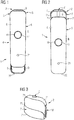
- the geometry and construction of the cover member 6 can be more clearly seen.
- the front panel 6' of the cover member is functionalized by its convex outer shape, its thickness and flexibility.
- the panel 6' is not only configured to move between the first and second positions A, B but may also bend and form as a user interface for operation of the device 1.
- the front panel 6' of the cover member 6 includes user interface elements, such as the switch 17 in the form of a button set within the opening 18 in the cover member 6 and surrounded by a ring-shaped indicator 19 which illuminates the front panel 6' for indicating an operational status of the device 1.
- the switch or button 17 which is configured to activate the device 1 for vapour generation after the cover member 6 has been moved to the second or "in-use" position B.
- the front panel 6' may also include one or more further switch or button 21 which may be positioned on a surface thereof (e.g. discretely or clearly) for activating additional functionalities, such as for setting an operating mode.
- Each of the switches or buttons 17, 21 is in operative connection with a part of the controller or control unit 13 of the device 1 below the cover member 6, which is described later.
- the indicator 17 may illuminate to identify that the device 1 has been activated and/or is ready for operation. Further, the indicator 20 may illuminate in a different colour and/or in a different manner (e.g.
- the opposite end region 22 of the body 4 of the e-cigarette 1 typically includes a connector 23 for connection to a re-charging dock or re-charging station and/or for connection of a re-charging cable.
- the underside of the front panel 6' includes sleeve elements 24 for sliding engagement with parallel rail members 25 (seen in Fig. 10 ) on the body portion 4 during longitudinal movement between the first and second positions A, B.
- the rail members 25 function as guide means for guiding the longitudinal movement of the cover member 6 and sleeve elements 24 form follower elements for following the path defined by the rails.
- the elongate body portion 4 of the device 1 includes a circuit board (not shown) mounted below the front panel 6' which forms part of the controller or control unit 13 of the e-cigarette.
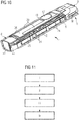
- FIG. 11 of the drawings a flow diagram is shown that illustrates schematically the steps in a method of installing a cartridge in a personal vaporizer device 1, especially in an electronic smoking article according to the embodiments of the invention described above with respect to Figs. 1 to 10 .
- the first box i of Fig. 11 thus represents the step of providing a personal vaporizer device 1 having an elongate body portion 4 to which a removable cartridge 2 is configured to be connected, the cartridge 2 including a reservoir 8 for storing a liquid to be vaporized.
- the second box ii represents the step of providing a cover member 6 on the elongate body portion 4 which is movable in a longitudinal direction of the body portion 4 between a first extended position A and a second retracted position B.
- the third box iii represents the step of moving cover member 6 to the second retracted position B to access an end region 3 of the body portion 4.
- the final box iv in Fig. 11 of the drawings represents the step of attaching the cartridge 2 to the accessed end region 3 of the body portion 4 personal vaporizer device 1.
Landscapes
- Health & Medical Sciences (AREA)
- Engineering & Computer Science (AREA)
- Anesthesiology (AREA)
- Biomedical Technology (AREA)
- Heart & Thoracic Surgery (AREA)
- Hematology (AREA)
- Life Sciences & Earth Sciences (AREA)
- Animal Behavior & Ethology (AREA)
- General Health & Medical Sciences (AREA)
- Public Health (AREA)
- Veterinary Medicine (AREA)
- Pulmonology (AREA)
- Bioinformatics & Cheminformatics (AREA)
- Human Computer Interaction (AREA)
- Chemical & Material Sciences (AREA)
- Chemical Kinetics & Catalysis (AREA)
- General Chemical & Material Sciences (AREA)
- Catching Or Destruction (AREA)
- Feeding And Controlling Fuel (AREA)
- Disinfection, Sterilisation Or Deodorisation Of Air (AREA)
- Packaging Of Annular Or Rod-Shaped Articles, Wearing Apparel, Cassettes, Or The Like (AREA)
- Containers And Packaging Bodies Having A Special Means To Remove Contents (AREA)
- Filling Or Discharging Of Gas Storage Vessels (AREA)
- Harvesting Machines For Specific Crops (AREA)
Description
- The present invention relates to a personal vaporizer device, such as an electronic smoking article.
- Personal vaporizer devices, such as electronic cigarettes or "e-cigarettes" as they are also known, have gained in popularity over the past ten years as an alternative to traditional smoking articles, like cigarettes, cigars, and cigarillos. Because the technology employed in personal vaporizer devices is still quite young, however, developments in the design and configuration of such devices are on-going to improve their performance and their reliability, as well as their ease of use, ease of production, and their production costs.
- In this context,
CN 204 157 645 U discloses a kind of electronic cigarette, comprising an electronic cigarette body, wherein the electronic cigarette body is provided with a smoke absorbing end, a tobacco tar bottle for storing tobacco tar, an atomization assembly for atomizing cigarette oil, which is electrically connected with an atomizing component and a battery for powering an atomizing component and a display module for showing electronic cigarette information. - Further,
EP 3 009 017 A shows a capsule containing a liquid to be supplied to an atomizer and being mounted on or in an electronic smoking device. The capsule has a controller including a memory, which receives data from and transmits data to control electronics of the electronic smoking device. A capacitor in the capsule is charged by the electronic smoking device and powers the controller during intermediate intervals. Electrical contacts of the capsule are connected to electrical contacts of the electronic smoking device to charge the capacitor and exchange data. - In view of the above, an object of the invention is to provide a new and improved personal vaporizer device, especially an improved electronic smoking article. In particular, it would be desirable to provide such a personal vaporizer device which is more ergonomic and user-friendly for a user. It would also be useful to provide such a personal vaporizer device which protects sensitive or replaceable parts or components of the device, such as a cartridge or capsule for holding a liquid to be vaporized, especially a disposable cartridge or a refillable cartridge.
- In accordance with the present invention, a personal vaporizer device, especially an electronic smoking article, as recited in claim 1, as well as a method of installing a cartridge in a personal vaporizer device as recited in
claim 14, are provided. Various preferred and/or advantageous features of the invention are recited in the dependent claims. According to an aspect, the invention provides a personal vaporizer device, especially an electronic smoking article, comprising: a removable cartridge which includes a reservoir for storing a liquid to be vaporized; and an elongate body portion to which the removable cartridge is connected. The elongate body portion includes a cover member which is movable in a longitudinal direction of the body portion between a first position and a second position, wherein the removable cartridge is at least partially, and optionally substantially entirely, covered or obscured by the cover member in the first position. As noted above, the cover member may thus provide a physical barrier for protecting the removable cartridge in the first position. - In relation to the cartridge being at least partially covered or obscured by the cover member in the first position, it will be noted that the cover member typically covers or obscures at least 50% of an outer surface of the cartridge in the first position, and more preferably at least 80% of an outer surface of the cartridge in the first position. In a preferred embodiment, the cover member covers or obscures in the range of 80% to 100% of the cartridge in the first position.
- In a preferred embodiment, the cover member may substantially cover or obscure a mouthpiece of the personal vaporizer device in the first position. In this way, the first position may be clearly designed or intended to form a non-use position or a non-activated position for the vaporizer device. The mouthpiece may, for example, be provided on the cartridge. In this context, the first position of the cover member may be a substantially extended position, in which the cover member extends in the longitudinal direction of the body portion to cover the cartridge and/or mouthpiece of the personal vaporizer device.
- In a preferred embodiment the cover member comprises at least one of a front cover panel, which extends over a front of the elongate body portion, and a rear cover panel, which extends over a rear of the elongate body portion. In this way, the cover member may form part of an outer casing of the elongate body portion.
- In a preferred embodiment, a volume of liquid in the reservoir of the cartridge is or remains visible when the cover member is in the first position. That is, although the cartridge is largely covered or obscured by the cover member in this position, a user is nevertheless able to check and see how much liquid is in the reservoir of the cartridge. In this regard, a window could be provided in the cover member. As an alternative, or in addition, the cover member need not fully enclose or encase the cartridge, thereby leaving an area or region uncovered for a user to determine visually what volume of liquid remains in the reservoir. For example, a side region of the cartridge could optionally remain uncovered by the cover member.
- In a preferred embodiment, the second position of the cover member may assume a substantially retracted position, with the cover member configured and arranged to leave the removable cartridge substantially uncovered or unobscured in the second position. That is, the cover member may be retracted from the removable cartridge in the longitudinal direction to the second position. Thus, this second position may be designed or intended to form a use position or an activated position for the vaporizer device. Further, the second position may be particularly suitable for connecting a removable cartridge to and/or for removing a removable cartridge from the body portion of the personal vaporizer device.
- In a preferred embodiment, the personal vaporizer device comprises guide means for guiding movement of the cover member in the longitudinal direction between the first position and the second position. In this regard, the cover member may, for example, be mounted on one or more tracks or rails provided in or on the body portion for movement of the cover member in the longitudinal direction between the first position and the second position. That is, the one or more tracks or rails may define a path of travel for the cover member between the first position and the second position. The cover member therefore preferably includes one or more complementary follower element configured for engaging a respective track or rail for following same along the predefined path of travel between the first and second positions. The movement of the cover member in the longitudinal direction may be a sliding movement, although rolling movement or other translational movement is also contemplated.
- In a preferred embodiment, the elongate body portion includes a switch which is configured to activate one or more functionality of the personal vaporizer device. In this regard, the switch is preferably provided either on the movable cover member or in operative connection with the cover member. In this way, the one or more functionality of the device may, for example, be activated via the switch when the cover member is moved to the first position and/or to the second position. For example, the device may include two separate functions which could be activated by movement of the cover member, with one function being activated when the cover member is in the first position, and another function being activated when the cover member is in the second position. Alternatively, or in addition, multiple functions could be activated in each of the first and/or second positions.
- In a preferred embodiment, the elongate body portion comprises a power supply unit, especially a battery unit, for supplying electrical power to the device. In this regard, the personal vaporizer device will typically include a vaporizer unit for vaporizing the liquid from the reservoir to be inhaled by a user. Furthermore, the vaporizer device may optionally include a control unit for controlling operation of the device. Thus, the power supply unit is desirably designed to supply electrical power to the vaporizer unit and/or to the control unit. In a particularly preferred embodiment, the vaporizer unit and/or the control unit may be incorporated in the cartridge which is configured to be connected to the elongate body portion of the device. Accordingly, in a preferred embodiment the vaporizer unit comprises a heater for heating the liquid to be vaporized to generate the vapour to be inhaled, and a liquid delivery means which is configured to convey the liquid from the reservoir to the heater for vaporization.
- As noted above, the cartridge is preferably configured to be connected to an end region of the elongate body portion in the vaporizer device. The end region of the elongate body portion thus preferably includes one or more electrical connectors for making an electrical connection with one or more complementary electrical connectors provided on the cartridge.
- Furthermore, in a preferred embodiment, the body portion has one or more indicator, especially an illuminated indicator, such as an LED, for indicating an operational status of the device and/or for indicating available power supply in a power supply unit of the elongate body portion.
- According to a further aspect, the present invention provides a personal vaporizer device, especially an electronic smoking article, configured to receive a removable cartridge with a reservoir for holding a liquid to be vaporized. The vaporizer device comprises an elongate body portion to which the cartridge is configured to be connected. The elongate body portion includes a power supply unit, especially a battery unit, for supplying electrical power to the device and at least one part of a controller or control unit for controlling operation of the device. A user interface for the control unit or controller is provided on an outer cover member of the elongate body portion and includes one or more user-interface elements over a longitudinal extent of the elongate body portion.
- In a preferred embodiment, the control unit or controller is configured to manage one or more of: a heater or heating function of the device; a power supply function of the device; and a capsule recognition function of the device. The control unit or controller typically comprises a user interface for the device. Preferably, one or more LEDs are provided to act or to serve as illuminated indicator elements for indicating an operational status of the device and/or for indicating available power supply in the power supply unit.
- In a preferred embodiment, the personal vaporizer device comprises one or more sensors for determining one or more operating condition of the device. The sensor or sensors may be incorporated in the cartridge and/or in the body portion of the device. The sensor(s) may, for example, include a temperature sensor, a liquid volume sensor, a puff sensor, and/or gyroscopic sensors.
- According to a further aspect, the invention also provides a method of installing a cartridge in a personal vaporizer device, comprising the steps of:
- providing a personal vaporizer device having an elongate body portion to which a removable cartridge is configured to be connected, the removable cartridge including a reservoir for storing a liquid to be vaporized and a mouthpiece provided on the removable cartridge;
- providing a cover member on the elongate body portion which is movable in a longitudinal direction of the body portion between a first extended position and a second retracted position;
- moving the cover member to the second retracted position to access an end region of the elongate body portion; and
- attaching the removable cartridge to the accessed end region of the elongate body portion of the personal vaporizer device.
- In an embodiment of the method, after attaching the removable cartridge to the end region of the elongate body portion, the cover member is moved to the first position to substantially cover the removable cartridge. As noted above, this has the effect of protecting the installed removable cartridge from external influences.
- In an embodiment of the method, after attaching the removable cartridge to the end region of the elongate body portion, movement of the cover member between the first position and the second positon may act to switch the personal vaporizer device between an activated and a deactivated state.
- For a more complete understanding of the invention and the advantages thereof, exemplary embodiments of the invention are explained in more detail in the following description with reference to the accompanying drawing figures, in which like reference characters designate like parts and in which:
- Fig. 1
- is a side view of a personal vaporizer device, especially an electronic smoking article, according to an embodiment, with a cover member of the device shown in a first position;
- Fig. 2
- is a side view of the personal vaporizer device shown in
Fig. 1 , with the cover member of the device shown in a first position; - Fig. 3
- is a perspective view of a cartridge for a personal vaporizer device according to an embodiment;
- Fig. 4
- is a schematic sectioned side view of a cartridge with vaporizer unit installed in a personal vaporizer device via a first type of connection;
- Fig. 5
- is a schematic sectioned side view of a cartridge with vaporizer unit installed in a personal vaporizer device via a second type of connection;
- Fig. 6
- is a schematic sectioned side view of a cartridge with vaporizer unit installed in a personal vaporizer device via a third type of connection;
- Fig. 7
- is a perspective view of the personal vaporizer device illustrated in
Figs. 1 and 2 , with the cover member shown in the first position; - Fig. 8
- is a perspective view of the cover member of the personal vaporizer device shown in
Figs. 1, 2 and7 ; - Fig. 9
- is a perspective view of an underside of the cover member shown in
Fig. 8 ; - Fig. 10
- is a perspective view of the personal vaporizer device shown in
Fig. 7 with the cover member represented transparent providing a view of the control unit and user interface elements; - Fig. 11
- is a flow diagram which schematically represents a method according to an embodiment of the invention.
- The accompanying drawings are included to provide a further understanding of the present invention and are incorporated in and constitute a part of this specification. The drawings illustrate particular embodiments of the invention and together with the description serve to explain the principles of the invention. Other embodiments of the invention and many of the attendant advantages of the invention will be readily appreciated as they become better understood with reference to the following detailed description.
- It will be appreciated that common and/or well understood elements that may be useful or necessary in a commercially feasible embodiment are not necessarily depicted in order to facilitate a more abstracted view of the embodiments. The elements of the drawings are not necessarily illustrated to scale relative to each other. It will further be appreciated that certain actions and/or steps in an embodiment of a method may be described or depicted in a particular order of occurrences while those skilled in the art will understand that such specificity with respect to sequence is not actually required. It will also be understood that the terms and expressions used in the present specification have the ordinary meaning as is accorded to such terms and expressions with respect to their corresponding respective areas of inquiry and study, except where specific meanings have otherwise been set forth herein.
- With reference firstly to
Figs. 1 and 2 of the drawings, a personal vaporizer device 1 in the form of electronic cigarette or "e-cigarette" is illustrated in different positions and in partial cross-section. The device 1 includes areplaceable cartridge 2 which is attached at one end region 3 of anelongate body 4. Theelongate body 4 in turn comprises acasing 5 which encloses a power supply unit in the form of a battery unit D for supplying electrical power to the device 1. Thecasing 5 of theelongate body 4 includes acover member 6 which is movable in a longitudinal direction of thebody 4 between a first position A (i.e. shown inFig. 1 ) and a second position B (i.e. shown inFig. 2 ). In this regard, thecover member 6 comprises a front cover panel 6' which extends over a front side of thebody 4, and arear cover panel 6", which extends over a rear side of thebody 4. - As can be seen in drawing
Figs. 2 , thecartridge 2 comprises ahousing 7 that encloses a reservoir 8 for storing a liquid to be vaporized. Thehousing 7 has a flat base 7' and generally vertically extendingsides 7" which transition at curved upper shoulder regions 7'" to form or terminate at amouthpiece 9 at a top of thecartridge 2. In this way, the shell of thehousing 7 encloses the reservoir 8 to form a small tank for storing the liquid (i.e. of a type known in the art) to be vaporized for inhalation by a user of the e-cigarette. Furthermore, thecartridge 2 includes an airflow channel C which extends centrally through thehousing 7 from the base 7' to the top and is configured to guide the vapour to themouthpiece 9 for inhalation by the user. The airflow channel C has a generally circular cross-section and is surrounded by the reservoir 8. In order to generate the vapour, thecartridge 2 incorporates a vaporizer unit having an electric heater with a heating element or wire provided wound in a coil within the airflow channel C for heating the liquid to be vaporized to generate the vapour to be inhaled. The vaporizer unit (not shown) further comprises a liquid delivery means which is configured to convey the liquid from the reservoir 8 to the heating wire for vaporization. - Referring to drawing
Figs. 1 and 2 , thecover member 6, which is comprised of the front andrear panel members 6', 6", is movable in a longitudinal direction of the device body 4 - e.g. by sliding or in translation - between the first position A shown inFig. 1 and the second position B shown inFig. 2 . In the first extended position A, thereplaceable cartridge 2 comprising the reservoir 8 and thevaporizer unit 10 is substantially covered or obscured by thecover member 6. In this way, thecover member 6 provides a physical barrier for protecting thecartridge 2 in the first position A. Nevertheless, the volume or amount of liquid in the reservoir 8 of thecartridge 2 remains visible when thecover member 6 is in the first position A. That is, although thecartridge 2 is largely covered or obscured bycover member 6 in this position, a window may be provided in thecover member 6 and/or a side region S of thecartridge 2 remains uncovered by thecover member 6 and may include a window W for a user to determine visually how much liquid remains in the reservoir 8. - For sliding or moving the
cover member 6 relative to the remainder of thecasing 5 between the first and second positions A, B, at least one or both of the front andrear panel members 6', 6" may be held and engaged between a thumb and finger of the user. In the second position B, thecover member 6 is retracted to leave thecartridge 2 either partially or substantially uncovered or unobscured. That is, in the second position B thecover member 6 is retracted from thecartridge 2 in the longitudinal direction to a use position or an activated position for the e-cigarette or vaporizer device 1. To this end, thebody 4 includes aswitch 17 provided in the form of a round button set within anopening 18 in thecover member 6. The switch orbutton 17 is configured to activate the device 1 and theswitch 17 is in operative connection with a part of the controller or control unit below thecover member 6. In this regard, the device 1 may be designed to only be able to be activated via theswitch 17 when the front andrear panels 6', 6" are moved from the first position A to the second position B. Theswitch 17 is surrounded by a ring-shapedindicator 19 which illuminates on the front panel 6' for indicating an operational status of the device 1. These elements of the vaporizer device 1 will be described in greater detail below. - In addition, the second position B of the
cover member 6 is designed for removing thecartridge 2 from, and/or for connecting acartridge 2 to, thebody portion 4 of the personal vaporizer device or e-cigarette 1. As noted above, thecartridge 2 is configured to be connected to the end region 3 of thebody portion 4. This end region 3 of theelongate body 4 thus preferably includes one or moreelectrical contacts 14 for making an electrical connection with one or more complementary electrical connectors provided on thecartridge 2 for connecting electrical power to the heater of the vaporizer unit within thecartridge 2. - Drawing
Fig. 3 shows a perspective view of acartridge 2 according to a similar embodiment to the one described above. As described previously, thecartridge 2 here typically includes ahousing 7 enclosing a reservoir 8 for storing the liquid to be vaporized and defining an airflow channel C which extends centrally through thehousing 7 to amouthpiece 9 at a top of thecartridge 2. Further, thecartridge 2 includes a vaporizer unit (not shown) having an electric heater with a heating element provided wound in a coil within the airflow channel C for heating the liquid to be vaporized to generate the vapour to be inhaled. The vaporizer unit comprises a liquid delivery means configured to convey the liquid from the reservoir 8 via capillary action or other known mechanisms. - Referring now to
Figs. 4 to 6 of the drawings, three different types of mechanical and electrical connections between thecartridge 2 and power supply (e.g. battery unit D) via the end region 3 of thebody 4 of the personal vaporizer device 1 are schematically illustrated. In each case, thecartridge 2 is configured for a push-on/pull-off type connection into the open upper end region 3 of thecasing 5 of the device. InFig. 4 , thesides 7" of thecartridge housing 7 include resilient or flexible members 31 (e.g. formed as leaf-springs or cantilevers) having projectinglugs 32 for receipt or engagement incomplementary recesses 33 formed on an inner side of thecasing 5.Electrical contact elements 14 are provided separately for power supply to the controller 13 and heater via electrical contacts provided below thecartridge 2. In the embodiment ofFig. 5 , thesides 7" of thecartridge housing 7 are received in the open upper end region 3 of thecasing 5 and resilientelectrical contact elements 14 extend upwards from the power supply and engageelectrical contacts 34 provided in thesides 7" of thecartridge housing 7. In the embodiment ofFig. 6 , by contrast, a mechanical connection is effected viamagnetic connector elements 35 provided on both thecartridge 2 and thebody part 4 of the personal vaporizer device 1 at the end region 3. The electrical connection again occurs separately viaelectrical contacts 14 below the base 7' of thecartridge housing 7. - With reference now to
Figs. 7 to 9 of the drawings, the geometry and construction of thecover member 6 can be more clearly seen. In particular, the front panel 6' of the cover member is functionalized by its convex outer shape, its thickness and flexibility. In particular, the panel 6' is not only configured to move between the first and second positions A, B but may also bend and form as a user interface for operation of the device 1. In this regard, it has already been noted above that the front panel 6' of thecover member 6 includes user interface elements, such as theswitch 17 in the form of a button set within theopening 18 in thecover member 6 and surrounded by a ring-shapedindicator 19 which illuminates the front panel 6' for indicating an operational status of the device 1. The switch orbutton 17 which is configured to activate the device 1 for vapour generation after thecover member 6 has been moved to the second or "in-use" position B. The front panel 6' may also include one or more further switch orbutton 21 which may be positioned on a surface thereof (e.g. discretely or clearly) for activating additional functionalities, such as for setting an operating mode. Each of the switches orbuttons cover member 6, which is described later. When thecover member 6 is moved to the second position B, theindicator 17 may illuminate to identify that the device 1 has been activated and/or is ready for operation. Further, the indicator 20 may illuminate in a different colour and/or in a different manner (e.g. blink or pulsate) to signal to a user that the available power supply in the battery unit D is low (e.g. that the battery unit D should be recharged). For this purpose, theopposite end region 22 of thebody 4 of the e-cigarette 1 typically includes aconnector 23 for connection to a re-charging dock or re-charging station and/or for connection of a re-charging cable. - As is apparent from drawing
Fig. 9 , the underside of the front panel 6' includessleeve elements 24 for sliding engagement with parallel rail members 25 (seen inFig. 10 ) on thebody portion 4 during longitudinal movement between the first and second positions A, B. In this way, therail members 25 function as guide means for guiding the longitudinal movement of thecover member 6 andsleeve elements 24 form follower elements for following the path defined by the rails. Further, referring to drawingFig. 10 , theelongate body portion 4 of the device 1 includes a circuit board (not shown) mounted below the front panel 6' which forms part of the controller or control unit 13 of the e-cigarette. - Finally, referring to
Fig. 11 of the drawings, a flow diagram is shown that illustrates schematically the steps in a method of installing a cartridge in a personal vaporizer device 1, especially in an electronic smoking article according to the embodiments of the invention described above with respect toFigs. 1 to 10 . In this regard, the first box i ofFig. 11 thus represents the step of providing a personal vaporizer device 1 having anelongate body portion 4 to which aremovable cartridge 2 is configured to be connected, thecartridge 2 including a reservoir 8 for storing a liquid to be vaporized. The second box ii represents the step of providing acover member 6 on theelongate body portion 4 which is movable in a longitudinal direction of thebody portion 4 between a first extended position A and a second retracted position B. The third box iii represents the step of movingcover member 6 to the second retracted position B to access an end region 3 of thebody portion 4. The final box iv inFig. 11 of the drawings represents the step of attaching thecartridge 2 to the accessed end region 3 of thebody portion 4 personal vaporizer device 1. -
- 1
- personal vaporizer device or e-cigarette
- 2
- cartridge
- 3
- end region of elongate body
- 4
- elongate body
- 5
- casing
- 6
- cover member
- 6'
- front panel
- 6"
- rear panel
- 7
- housing
- 7'
- housing base
- 7"
- housing sides
- 7'"
- housing shoulder region
- 8
- reservoir
- 9
- mouthpiece
- 10
- vaporizer unit
- 14
- electrical contact
- 15
- conductor element
- 17
- switch or button
- 18
- opening in the cover member
- 19
- ring-shaped indicator
- 21
- mode switch or button
- 22
- opposite end region of body portion
- 23
- charging connector
- 24
- sleeve element
- 25
- rail member
- 26
- circuit board
- 29
- light-guide element
- 31
- resilient or flexible member
- 32
- projecting lug
- 33
- recess
- 34
- electrical contact
- 35
- magnetic connector element
- A
- first position of cover member
- B
- second position of cover member
- D
- battery unit
- C
- airflow channel
- S
- sides of the casing
- W
- window
Claims (15)
- A personal vaporizer device (1), comprising:a cartridge (2) which includes a reservoir (8) for storing a liquid to be vaporized, andan elongate body portion (4) to which the cartridge (2) is connected, wherein the elongate body portion (4) comprises a cover member (6) which is movable in a longitudinal direction of the elongate body portion (4) between a first position (A) and a second position (B),wherein the cartridge (2) is at least partially covered or obscured by the cover member (6) in the first position (A), characterised in thatthe cartridge (2) comprises a housing (7) that encloses the reservoir (8), the cartridge (2) is configured to be connected to an end region (3) of the elongate body portion (4) and wherein a mouthpiece (9) is provided on the cartridge (2).
- A personal vaporizer device (1) according to claim 1, wherein a volume of liquid in the reservoir (8) of the cartridge (2) remains visible when the cover member (6) is in the first position (A).
- A personal vaporizer device (1) according to claim 2, wherein a window is provided in the cover member (6) and/or a side region (S) of the cartridge (2) remains uncovered by the cover member (6) for a user to determine visually how much liquid remains in the reservoir (8) of the cartridge (2) when the cover member (6) is in the first position (A).
- A personal vaporizer device (1) according to any preceding claim, wherein the cartridge (2) includes a window (W) for a user to determine visually how much liquid remains in the reservoir (8) of the cartridge (2), the window (W) preferably being provided on a side region (S) of the cartridge (2).
- A personal vaporizer device (1) according to any preceding claim, wherein the second position (B) of the cover member (6) is a substantially retracted position in which the cartridge (2) is substantially uncovered or unobscured by the cover member (6), for connection of the cartridge (2) to, and/or removal of the cartridge (2) from, the elongate body portion (4), the second position (B) preferably being a position in which the personal vaporizer device (1) is activated.
- A personal vaporizer device (1) according to any preceding claim, wherein the first position (A) of the cover member (6) is a substantially extended position, the first position (A) preferably being a position in which the personal vaporizer device (1) is deactivated.
- A personal vaporizer device (1) according to any preceding claim, wherein the cover member (6) forms a part of an outer casing (5) of the elongate body portion (4).
- A personal vaporizer device (1) according to claim 7, wherein the cover member (6) comprises at least one of a front cover panel (6') which extends over a front of the elongate body portion (4) and a rear cover panel (6") which extends over a rear of the elongate body portion (4).
- A personal vaporizer device (1) according to any preceding claim, further comprising at least one sensor for determining one or more operating conditions of the personal vaporizer device (1), wherein the at least one sensor is incorporated in the cartridge (2) and/or the elongate body portion (4), and wherein the at least one sensor comprises a temperature sensor, a liquid volume sensor, a puff sensor, or a gyroscopic sensor.
- A personal vaporizer device (1) according to any preceding claim, wherein the cover member (6) covers or obscures at least 50% of an outer surface of the cartridge (2) in the first position (A), preferably at least 80% of an outer surface of the cartridge (2), more preferably in the range of 80% to 100% of the cartridge (2).
- A personal vaporizer device (1) according to any preceding claim, wherein the elongate body portion (4) comprises a switch (17) operatively connected with the cover member (6) and configured to activate at least one functionality when the cover member (6) is moved to the first position (A) and/or to the second position (B), and wherein the elongate body portion (4) comprises at least one indicator (19), preferably an illuminated indicator, such as an LED, for indicating an operational status of the personal vaporizer device (1).
- A personal vaporizer device (1) according to claim 11, wherein the switch (17) is configured to activate the personal vaporizer device (1) for vapour generation after the cover member (6) has been moved to the second position (B), and wherein the at least one indicator (19) is configured to indicate that the personal vaporizer device (1) has been activated.
- A personal vaporizer device (1) according to any preceding claim, further comprising guide means (25) for guiding movement of the cover member (6) in the longitudinal direction between the first position (A) and the second position (B).
- A method of installing a removable cartridge (2) in a personal vaporizer device (1), especially in an electronic smoking article, comprising the steps of:providing a personal vaporizer device (1) having an elongate body portion (4) to which the removable cartridge (2) is configured to be connected, the removable cartridge (2) including a housing that encloses a reservoir (8) for storing a liquid to be vaporized and a mouthpiece (9) provided on the removable cartridge (2);providing a cover member (6) on the elongate body portion (4) which is movable in a longitudinal direction of the body portion (4) between a first extended position (A) and a second retracted position (B);moving cover member (6) to the second retracted position (B) to access an end region (3) of the elongate body portion (4); andattaching the removable cartridge (2) to the accessed end region (3) of the elongate body portion (4) of the personal vaporizer device (1).
- A method according to claim 14, comprising the step of: after attaching the removable cartridge (2) to the end region (3) of the elongate body portion (4), moving the cover member (6) to the first extended position (A) to substantially cover the removable cartridge (2).
Priority Applications (6)
| Application Number | Priority Date | Filing Date | Title |
|---|---|---|---|
| EP21154281.6A EP3871519A1 (en) | 2015-12-18 | 2016-12-15 | Personal vaporizer device |
| RS20210310A RS61567B1 (en) | 2015-12-18 | 2016-12-15 | Personal vaporizer device |
| SI201631125T SI3386323T1 (en) | 2015-12-18 | 2016-12-15 | Personal vaporizer device |
| EP20214564.5A EP3821724B1 (en) | 2015-12-18 | 2016-12-15 | Cartridge and personal vaporizer device |
| HRP20210404TT HRP20210404T1 (en) | 2015-12-18 | 2016-12-15 | Personal vaporizer device |
| PL16809444T PL3386323T3 (en) | 2015-12-18 | 2016-12-15 | Personal vaporizer device |
Applications Claiming Priority (2)
| Application Number | Priority Date | Filing Date | Title |
|---|---|---|---|
| EP15201281 | 2015-12-18 | ||
| PCT/EP2016/081231 WO2017102969A1 (en) | 2015-12-18 | 2016-12-15 | Personal vaporizer device |
Related Child Applications (3)
| Application Number | Title | Priority Date | Filing Date |
|---|---|---|---|
| EP20214564.5A Division EP3821724B1 (en) | 2015-12-18 | 2016-12-15 | Cartridge and personal vaporizer device |
| EP20214564.5A Division-Into EP3821724B1 (en) | 2015-12-18 | 2016-12-15 | Cartridge and personal vaporizer device |
| EP21154281.6A Division EP3871519A1 (en) | 2015-12-18 | 2016-12-15 | Personal vaporizer device |
Publications (2)
| Publication Number | Publication Date |
|---|---|
| EP3386323A1 EP3386323A1 (en) | 2018-10-17 |
| EP3386323B1 true EP3386323B1 (en) | 2021-02-03 |
Family
ID=54979479
Family Applications (3)
| Application Number | Title | Priority Date | Filing Date |
|---|---|---|---|
| EP21154281.6A Withdrawn EP3871519A1 (en) | 2015-12-18 | 2016-12-15 | Personal vaporizer device |
| EP20214564.5A Active EP3821724B1 (en) | 2015-12-18 | 2016-12-15 | Cartridge and personal vaporizer device |
| EP16809444.9A Active EP3386323B1 (en) | 2015-12-18 | 2016-12-15 | Personal vaporizer device |
Family Applications Before (2)
| Application Number | Title | Priority Date | Filing Date |
|---|---|---|---|
| EP21154281.6A Withdrawn EP3871519A1 (en) | 2015-12-18 | 2016-12-15 | Personal vaporizer device |
| EP20214564.5A Active EP3821724B1 (en) | 2015-12-18 | 2016-12-15 | Cartridge and personal vaporizer device |
Country Status (20)
| Country | Link |
|---|---|
| US (2) | US20180360125A1 (en) |
| EP (3) | EP3871519A1 (en) |
| JP (3) | JP6857658B2 (en) |
| KR (1) | KR102738815B1 (en) |
| CN (3) | CN115474719A (en) |
| CA (1) | CA3008383A1 (en) |
| CY (1) | CY1124235T1 (en) |
| DK (1) | DK3386323T3 (en) |
| EA (2) | EA202092986A3 (en) |
| ES (2) | ES2863570T3 (en) |
| HR (1) | HRP20210404T1 (en) |
| HU (1) | HUE053803T2 (en) |
| LT (1) | LT3386323T (en) |
| PL (2) | PL3821724T3 (en) |
| PT (1) | PT3386323T (en) |
| RS (1) | RS61567B1 (en) |
| SI (1) | SI3386323T1 (en) |
| TW (1) | TWI631908B (en) |
| WO (1) | WO2017102969A1 (en) |
| ZA (1) | ZA201804154B (en) |
Families Citing this family (68)
| Publication number | Priority date | Publication date | Assignee | Title |
|---|---|---|---|---|
| US10244793B2 (en) | 2005-07-19 | 2019-04-02 | Juul Labs, Inc. | Devices for vaporization of a substance |
| US10279934B2 (en) | 2013-03-15 | 2019-05-07 | Juul Labs, Inc. | Fillable vaporizer cartridge and method of filling |
| US10058129B2 (en) | 2013-12-23 | 2018-08-28 | Juul Labs, Inc. | Vaporization device systems and methods |
| USD825102S1 (en) | 2016-07-28 | 2018-08-07 | Juul Labs, Inc. | Vaporizer device with cartridge |
| US10159282B2 (en) | 2013-12-23 | 2018-12-25 | Juul Labs, Inc. | Cartridge for use with a vaporizer device |
| US20160366947A1 (en) | 2013-12-23 | 2016-12-22 | James Monsees | Vaporizer apparatus |
| USD842536S1 (en) | 2016-07-28 | 2019-03-05 | Juul Labs, Inc. | Vaporizer cartridge |
| US10076139B2 (en) | 2013-12-23 | 2018-09-18 | Juul Labs, Inc. | Vaporizer apparatus |
| KR102721939B1 (en) | 2013-12-23 | 2024-10-25 | 쥴 랩스, 인크. | Vaporization device systems and methods |
| KR20250012730A (en) | 2014-12-05 | 2025-01-24 | 쥴 랩스, 인크. | Calibrated dose control |
| ES2863570T3 (en) | 2015-12-18 | 2021-10-11 | Jt Int Sa | Personal vaporizer device |
| MX388616B (en) | 2016-02-11 | 2025-03-20 | Juul Labs Inc | SECURE FITTING CARTRIDGES FOR VAPORIZING DEVICES |
| MX377347B (en) | 2016-02-11 | 2025-03-07 | Juul Labs Inc | Fillable vaporizer cartridge and method of filling |
| US10405582B2 (en) | 2016-03-10 | 2019-09-10 | Pax Labs, Inc. | Vaporization device with lip sensing |
| USD849996S1 (en) | 2016-06-16 | 2019-05-28 | Pax Labs, Inc. | Vaporizer cartridge |
| USD851830S1 (en) | 2016-06-23 | 2019-06-18 | Pax Labs, Inc. | Combined vaporizer tamp and pick tool |
| USD836541S1 (en) | 2016-06-23 | 2018-12-25 | Pax Labs, Inc. | Charging device |
| USD885656S1 (en) * | 2016-12-01 | 2020-05-26 | Jt International S.A. | Electronic cigarette |
| WO2018111879A1 (en) | 2016-12-12 | 2018-06-21 | Vmr Products Llc | Vaporizer |
| USD887632S1 (en) | 2017-09-14 | 2020-06-16 | Pax Labs, Inc. | Vaporizer cartridge |
| WO2019068489A1 (en) * | 2017-10-03 | 2019-04-11 | Philip Morris Products S.A. | Heater for aerosol-generating device with connectors |
| GB201718570D0 (en) * | 2017-11-09 | 2017-12-27 | Eweidah Fadi | Compact sized vaping device |
| KR200493437Y1 (en) * | 2017-12-25 | 2021-03-29 | 상하이 뉴 토바코 프로덕트 리서치 인스티튜트 컴퍼니 리미티드 | Aerosol-generating device and electronic cigarette |
| USD865278S1 (en) * | 2018-02-05 | 2019-10-29 | Shenzhen Transpring Enterprise Ltd. | Vape part |
| EP3560362A1 (en) * | 2018-04-24 | 2019-10-30 | JT International SA | Electronic cigarette with protective cover |
| KR20200142514A (en) | 2018-04-24 | 2020-12-22 | 제이티 인터내셔널 소시에떼 아노님 | Electronic cigarette with protective cover |
| US10888125B2 (en) | 2018-06-27 | 2021-01-12 | Juul Labs, Inc. | Vaporizer device with subassemblies |
| TW202011845A (en) * | 2018-07-24 | 2020-04-01 | 瑞士商傑太日煙國際股份有限公司 | Side-by-side terminal for personal vaporizing device |
| EP3833204A4 (en) | 2018-08-10 | 2022-05-25 | Furna Inc. | MOVING HEAD SPRAY APPARATUS AND RELATED METHODS |
| USD951535S1 (en) * | 2018-09-26 | 2022-05-10 | Philip Morris Products S.A. | Aerosol generating device |
| FR3086867A1 (en) * | 2018-10-08 | 2020-04-10 | Juul Labs, Inc. | Charging adapter assembly for a vaporizer |
| US11974603B2 (en) | 2018-10-12 | 2024-05-07 | Rai Strategic Holdings, Inc. | Aerosol delivery device with visible indicator |
| US11678700B2 (en) | 2018-10-12 | 2023-06-20 | Rai Strategic Holdings, Inc. | Aerosol delivery device with visible indicator |
| US10939702B2 (en) | 2018-10-12 | 2021-03-09 | Rai Strategic Holdings, Inc. | Connectors for forming electrical and mechanical connections between interchangeable units in an aerosol delivery system |
| US10791767B2 (en) * | 2018-10-12 | 2020-10-06 | Rai Strategic Holdings, Inc. | Connectors for forming electrical and mechanical connections between interchangeable units in an aerosol delivery system |
| US12232526B2 (en) | 2018-10-12 | 2025-02-25 | Rai Strategic Holdings, Inc. | Connectors for forming electrical and mechanical connections between interchangeable units in an aerosol delivery system |
| US11502466B2 (en) | 2018-10-12 | 2022-11-15 | Rai Strategic Holdings, Inc. | Aerosol delivery device with improved connectivity, airflow, and aerosol paths |
| EP3876761A1 (en) | 2018-11-05 | 2021-09-15 | Juul Labs, Inc. | Cartridges for vaporizer devices |
| USD928400S1 (en) * | 2018-11-05 | 2021-08-17 | Philip Morris Products S.A. | Device for generating nicotine containing aerosol for inhalation |
| US11156766B2 (en) * | 2018-11-19 | 2021-10-26 | Rai Strategic Holdings, Inc. | Aerosol delivery device |
| JP1652040S (en) * | 2019-01-29 | 2020-02-03 | Electronic Cigarette | |
| KR102253048B1 (en) * | 2019-04-25 | 2021-05-17 | 주식회사 케이티앤지 | Recharging system for aerosol generating apparatus |
| KR20220008836A (en) * | 2019-05-16 | 2022-01-21 | 필립모리스 프로덕츠 에스.에이. | A method for assembling a device and a device manufactured according to the method |
| CN110179164B (en) * | 2019-06-12 | 2024-05-24 | 陈玉水 | Electronic cigarette component |
| CN112273721B (en) * | 2019-07-12 | 2025-06-13 | 深圳市卓力能技术有限公司 | An aerosol generating device |
| CN112205673B (en) * | 2019-07-12 | 2025-06-13 | 深圳市卓力能技术有限公司 | An aerosol generating device |
| EP4021220B1 (en) * | 2019-08-30 | 2025-04-09 | JT International SA | Mouthpiece portion for an electronic cigarette |
| CN114269173A (en) * | 2019-08-30 | 2022-04-01 | 日本烟草国际股份有限公司 | Nozzle part for electronic cigarette |
| KR102390421B1 (en) | 2019-10-11 | 2022-04-25 | 주식회사 케이티앤지 | Aerosol generating device and method for showing the remaining amount of liquid composition using light source |
| US11564416B2 (en) | 2019-11-26 | 2023-01-31 | Altria Client Services Llc | Non-nicotine pod assemblies and non-nicotine e-vaping devices |
| US11528938B2 (en) | 2019-11-26 | 2022-12-20 | Altria Client Services Llc | Non-nicotine pod assemblies and non-nicotine e-vaping devices |
| US11596172B2 (en) | 2019-11-26 | 2023-03-07 | Altria Client Services Llc | Non-nicotine pod assemblies and non-nicotine e-vaping devices |
| US11490656B2 (en) | 2019-11-26 | 2022-11-08 | Altria Client Services Llc | Nicotine pod assemblies and nicotine e-vaping devices |
| US11528937B2 (en) | 2019-11-26 | 2022-12-20 | Altria Client Services Llc | Nicotine pod assemblies and nicotine e-vaping devices |
| US11528939B2 (en) | 2019-11-26 | 2022-12-20 | Altria Client Services Llc | Non-nicotine pod assemblies and non-nicotine e-vaping devices |
| US11484062B2 (en) | 2019-11-26 | 2022-11-01 | Altria Client Services Llc | Nicotine pod assemblies and nicotine e-vaping devices |
| US11576432B2 (en) | 2019-11-26 | 2023-02-14 | Altria Client Services Llc | Nicotine pod assemblies and nicotine e-vaping devices |
| US20230000156A1 (en) * | 2019-12-20 | 2023-01-05 | Furna Inc. | Vaporizer apparatus having reversible head and related methods |
| CN111067148A (en) * | 2020-03-03 | 2020-04-28 | 泰州亚泽塑胶有限公司 | Electron cigarette holder propelling movement assembly |
| KR20220155291A (en) * | 2020-03-18 | 2022-11-22 | 제이티 인터내셔널 소시에떼 아노님 | Aerosol generating device with a movable panel to cover the interface |
| US11856986B2 (en) | 2020-10-19 | 2024-01-02 | Rai Strategic Holdings, Inc. | Customizable panel for aerosol delivery device |
| US20230404168A1 (en) * | 2020-11-06 | 2023-12-21 | Jt International S.A. | Aerosol Generation Device |
| CN117355230A (en) * | 2021-04-28 | 2024-01-05 | 日本烟草产业株式会社 | Scent absorber and method of manufacturing the scent absorber |
| KR102715289B1 (en) * | 2021-05-28 | 2024-10-11 | 신종수 | Electronic Cigarette |
| US12127587B2 (en) * | 2021-11-16 | 2024-10-29 | Ivision Tech Inc. | Dual vaporizer |
| JP2024056340A (en) | 2022-10-11 | 2024-04-23 | 株式会社日本製鋼所 | Hopper of injection molding machine, injection unit, and injection molding machine |
| US20240164454A1 (en) * | 2022-11-18 | 2024-05-23 | Pangea Proper LLC | Vapor inhalation device including a pivot for rotating |
| JP2026510315A (en) * | 2023-03-10 | 2026-04-02 | ニコベンチャーズ トレーディング リミテッド | User interface for aerosol supply devices |
Family Cites Families (67)
| Publication number | Priority date | Publication date | Assignee | Title |
|---|---|---|---|---|
| GB531704A (en) | 1939-07-29 | 1941-01-09 | John Cartner | Improvements in and relating to containers for inhalants |
| CN1131676C (en) * | 1994-02-25 | 2003-12-24 | 菲利普莫里斯生产公司 | Electric smoking system and cigarette for delivering cigarette aroma |
| US6606992B1 (en) * | 1999-06-30 | 2003-08-19 | Nektar Therapeutics | Systems and methods for aerosolizing pharmaceutical formulations |
| UA80123C2 (en) | 2002-04-09 | 2007-08-27 | Boehringer Ingelheim Pharma | Inhalation kit comprising inhalable powder of tiotropium |
| US7726320B2 (en) | 2006-10-18 | 2010-06-01 | R. J. Reynolds Tobacco Company | Tobacco-containing smoking article |
| EP2044967A1 (en) | 2007-10-01 | 2009-04-08 | Boehringer Ingelheim Pharma GmbH & Co. KG | Atomiser |
| AT507187B1 (en) | 2008-10-23 | 2010-03-15 | Helmut Dr Buchberger | INHALER |
| US8851068B2 (en) * | 2009-04-21 | 2014-10-07 | Aj Marketing Llc | Personal inhalation devices |
| CN102970885B (en) * | 2010-04-30 | 2015-05-20 | 洛艾克有限公司 | Electronic smoking device |
| KR200465795Y1 (en) * | 2011-01-07 | 2013-03-11 | 이영인 | Electronic smoking device |
| US9763477B2 (en) | 2011-03-30 | 2017-09-19 | Shenzhen Kanger Technology Co., Ltd. | Ceramic heating elements for electronic cigarettes |
| KR20120008751U (en) | 2011-06-13 | 2012-12-24 | 이영찬 | an electronic cigarette |
| US8528569B1 (en) * | 2011-06-28 | 2013-09-10 | Kyle D. Newton | Electronic cigarette with liquid reservoir |
| KR200460784Y1 (en) | 2011-10-17 | 2012-06-11 | 주식회사 시그닛코리아 | Electronic cigarette |
| CN202385728U (en) | 2011-11-25 | 2012-08-22 | 周学武 | Electronic cigarette with built-in atomizer |
| TWI584745B (en) | 2012-01-03 | 2017-06-01 | 菲利浦莫里斯製品股份有限公司 | Non-rolling aerosol-generating device and system |
| WO2013174001A1 (en) | 2012-05-24 | 2013-11-28 | 深圳葆威道科技有限公司 | Constant-temperature atomizer with no tar leakage and liquid cigarette tar repeatedly added |
| CN202635604U (en) | 2012-06-18 | 2013-01-02 | 刘团芳 | Oval electronic cigarette |
| CN203776160U (en) | 2012-06-20 | 2014-08-20 | 惠州市吉瑞科技有限公司 | Electronic cigarette and electronic cigarette device |
| US9271527B2 (en) | 2012-06-20 | 2016-03-01 | Huizhou Kimree Technology Co., Ltd., Shenzhen Branch | Electronic cigarette and electronic cigarette device |
| WO2014008623A1 (en) | 2012-07-09 | 2014-01-16 | Liu Qiuming | Electronic cigarette |
| WO2014085999A1 (en) * | 2012-12-05 | 2014-06-12 | Liu Qiuming | Magnetic connection electronic cigarette with connector |
| US9993023B2 (en) * | 2013-02-22 | 2018-06-12 | Altria Client Services Llc | Electronic smoking article |
| TWI568370B (en) * | 2013-03-26 | 2017-02-01 | 富特姆控股第一有限公司 | Electronic cigarette and method of vaporizing a liquid in an electronic cigarette |
| CN111642812A (en) * | 2013-06-14 | 2020-09-11 | 尤尔实验室有限公司 | Multiple heating elements with individual vaporizable materials in electronic vaporization devices |
| US20140373857A1 (en) * | 2013-06-20 | 2014-12-25 | Dan Steinberg | Herbal Vaporizing Device |
| GB2515562B (en) * | 2013-06-28 | 2016-04-06 | Totally Wicked Ltd | Vaporiser unit and fluid reservoir for an atomiser |
| CN203388269U (en) | 2013-07-25 | 2014-01-15 | 刘秋明 | Electronic cigarette |
| HUE071661T2 (en) * | 2013-08-06 | 2025-09-28 | Fontem Ventures Bv | Electronic smoking device and process of manufacturing thereof |
| CN203466247U (en) * | 2013-08-27 | 2014-03-05 | 深圳市合元科技有限公司 | Electronic cigarette power supply device and electronic cigarette |
| WO2015027470A1 (en) | 2013-08-30 | 2015-03-05 | Liu Shuigen | Atomizer and electronic cigarette comprised of atomizer |
| US20150114406A1 (en) * | 2013-10-25 | 2015-04-30 | Kyle D. Newton | Electronic Cigarette with Replaceable Soft Tip Mouthpiece |
| US10039321B2 (en) | 2013-11-12 | 2018-08-07 | Vmr Products Llc | Vaporizer |
| HUE071643T2 (en) * | 2013-12-03 | 2025-09-28 | Philip Morris Products Sa | Aerosol-generating article and electrically operated system incorporating a taggant |
| US20150216237A1 (en) | 2014-01-22 | 2015-08-06 | E-Nicotine Technology, Inc. | Methods and devices for smoking urge relief |
| CN203789137U (en) | 2014-01-26 | 2014-08-27 | 深圳市合元科技有限公司 | Baking type smoke generating device and smoke sucking-in device |
| JP6655020B2 (en) * | 2014-02-10 | 2020-02-26 | フィリップ・モーリス・プロダクツ・ソシエテ・アノニム | Heater assembly for aerosol generation system |
| JP6755180B2 (en) * | 2014-02-10 | 2020-09-16 | フィリップ・モーリス・プロダクツ・ソシエテ・アノニム | Cartridges for aerosol generation systems with heater assemblies and aerosol generation systems with fluid permeable heater assemblies |
| US9597466B2 (en) * | 2014-03-12 | 2017-03-21 | R. J. Reynolds Tobacco Company | Aerosol delivery system and related method, apparatus, and computer program product for providing control information to an aerosol delivery device via a cartridge |
| US11696604B2 (en) * | 2014-03-13 | 2023-07-11 | Rai Strategic Holdings, Inc. | Aerosol delivery device and related method and computer program product for controlling an aerosol delivery device based on input characteristics |
| CN103948174B (en) | 2014-03-27 | 2017-08-08 | 深圳麦克韦尔股份有限公司 | Electronic cigarette |
| EP2929903B1 (en) | 2014-04-08 | 2018-05-09 | Shenzhen First Union Technology Co., Ltd. | Atomizer and electronic cigarette |
| CN204157645U (en) * | 2014-04-14 | 2015-02-18 | 惠州市吉瑞科技有限公司 | Electronic cigarette |
| RU2674714C2 (en) * | 2014-04-30 | 2018-12-12 | Филип Моррис Продактс С.А. | Container, having heater for aerosol-generating device, and aerosol-generating device |
| WO2015180167A1 (en) | 2014-05-30 | 2015-12-03 | 深圳麦克韦尔股份有限公司 | Electronic cigarette and atomizer thereof |
| US20150342255A1 (en) * | 2014-05-30 | 2015-12-03 | Shenzhen Jieshibo Technology Co., Ltd. | Electronic atomization device with adjustable air inlet |
| KR20240136452A (en) * | 2014-07-11 | 2024-09-13 | 필립모리스 프로덕츠 에스.에이. | Aerosol-forming cartridge comprising a liquid nicotine source |
| CN203986131U (en) * | 2014-07-31 | 2014-12-10 | 张银虎 | The electronic cigarette that a kind of atomizer is built-in |
| GB2529201A (en) | 2014-08-13 | 2016-02-17 | Batmark Ltd | Device and method |
| CN204335831U (en) | 2014-08-14 | 2015-05-20 | 惠州市吉瑞科技有限公司 | Atomizer and electronic cigarette |
| PL3009017T3 (en) * | 2014-10-14 | 2021-01-11 | Fontem Holdings 1 B.V. | Electronic smoking device and cartridge |
| JP6710684B2 (en) | 2014-11-17 | 2020-06-17 | マクニール アーベーMcneil Ab | Disposable cartridge for use in electronic nicotine delivery system |
| US20160150828A1 (en) * | 2014-12-02 | 2016-06-02 | Gabriel Marc Goldstein | Vaporizing reservoir |
| CN104544570B (en) | 2014-12-31 | 2017-12-08 | 深圳麦克韦尔股份有限公司 | Inhalator and its atomizing component |
| CN104738816B (en) * | 2015-02-04 | 2024-08-02 | 深圳市合元科技有限公司 | Atomizer, electronic cigarette and liquid storage device suitable for replacement |
| CN204444258U (en) | 2015-02-13 | 2015-07-08 | 林光榕 | Electronic smoke atomizer |
| AU2016257164B2 (en) * | 2015-02-25 | 2020-09-17 | Lumenary Inc. | Handheld apparatus for vaporization of plant-based or synthetic compounds by laser |
| US10064432B2 (en) * | 2015-04-22 | 2018-09-04 | Altria Client Services Llc | Pod assembly, dispensing body, and E-vapor apparatus including the same |
| CN204670386U (en) | 2015-04-29 | 2015-09-30 | 深圳市合元科技有限公司 | Atomizer and use the electronic cigarette of this atomizer |
| CN204682533U (en) | 2015-05-22 | 2015-10-07 | 深圳市腾烟科技有限公司 | A kind of electronic smoke atomizer with lock functional oil |
| EP3103355A1 (en) | 2015-06-08 | 2016-12-14 | Shenzhen Smaco Technology Limited | Electronic cigarette and an atomizing device thereof |
| GB201511349D0 (en) | 2015-06-29 | 2015-08-12 | Nicoventures Holdings Ltd | Electronic aerosol provision systems |
| GB201511359D0 (en) * | 2015-06-29 | 2015-08-12 | Nicoventures Holdings Ltd | Electronic vapour provision system |
| KR20170006253A (en) * | 2015-07-07 | 2017-01-17 | 주식회사 케이티앤지 | Electronic cigarette |
| GB2542838B (en) * | 2015-10-01 | 2022-01-12 | Nicoventures Trading Ltd | Aerosol provision system |
| ES2863570T3 (en) | 2015-12-18 | 2021-10-11 | Jt Int Sa | Personal vaporizer device |
| GB2550540B (en) * | 2016-03-24 | 2021-09-29 | Nicoventures Trading Ltd | Vapour provision device |
-
2016
- 2016-12-15 ES ES16809444T patent/ES2863570T3/en active Active
- 2016-12-15 EP EP21154281.6A patent/EP3871519A1/en not_active Withdrawn
- 2016-12-15 EA EA202092986A patent/EA202092986A3/en unknown
- 2016-12-15 EA EA201891382A patent/EA037265B1/en unknown
- 2016-12-15 HR HRP20210404TT patent/HRP20210404T1/en unknown
- 2016-12-15 CA CA3008383A patent/CA3008383A1/en active Pending
- 2016-12-15 WO PCT/EP2016/081231 patent/WO2017102969A1/en not_active Ceased
- 2016-12-15 SI SI201631125T patent/SI3386323T1/en unknown
- 2016-12-15 EP EP20214564.5A patent/EP3821724B1/en active Active
- 2016-12-15 CN CN202211347849.7A patent/CN115474719A/en active Pending
- 2016-12-15 CN CN202211347496.0A patent/CN115474718A/en active Pending
- 2016-12-15 JP JP2018532155A patent/JP6857658B2/en not_active Expired - Fee Related
- 2016-12-15 PL PL20214564.5T patent/PL3821724T3/en unknown
- 2016-12-15 KR KR1020187019999A patent/KR102738815B1/en active Active
- 2016-12-15 PT PT168094449T patent/PT3386323T/en unknown
- 2016-12-15 US US16/061,973 patent/US20180360125A1/en not_active Abandoned
- 2016-12-15 HU HUE16809444A patent/HUE053803T2/en unknown
- 2016-12-15 EP EP16809444.9A patent/EP3386323B1/en active Active
- 2016-12-15 DK DK16809444.9T patent/DK3386323T3/en active
- 2016-12-15 RS RS20210310A patent/RS61567B1/en unknown
- 2016-12-15 CN CN201680073881.7A patent/CN108601400A/en active Pending
- 2016-12-15 ES ES20214564T patent/ES2952570T3/en active Active
- 2016-12-15 LT LTEP16809444.9T patent/LT3386323T/en unknown
- 2016-12-15 PL PL16809444T patent/PL3386323T3/en unknown
- 2016-12-16 TW TW105141954A patent/TWI631908B/en not_active IP Right Cessation
-
2018
- 2018-06-21 ZA ZA2018/04154A patent/ZA201804154B/en unknown
-
2021
- 2021-03-16 JP JP2021042687A patent/JP7122425B2/en active Active
- 2021-04-21 CY CY20211100345T patent/CY1124235T1/en unknown
-
2022
- 2022-08-08 JP JP2022126535A patent/JP2022163142A/en active Pending
- 2022-11-21 US US17/991,434 patent/US20230082657A1/en active Pending
Non-Patent Citations (1)
| Title |
|---|
| None * |
Also Published As
Similar Documents
| Publication | Publication Date | Title |
|---|---|---|
| US20230082657A1 (en) | Personal Vaporizer Device | |
| CN112004426B (en) | Electronic cigarette with protective cover | |
| CN109717513B (en) | Electric heating smoke system | |
| KR20200142514A (en) | Electronic cigarette with protective cover | |
| RU2745911C1 (en) | Device for electronic aerosol generation system, method for manufacturing such device, aerosol forming unit for such device and aerosol supply system | |
| JP7832918B2 (en) | Aerosol generator | |
| EP4401590B1 (en) | Aerosol delivery device/system | |
| JP2024528828A (en) | Aerosol Generator | |
| US20260060310A1 (en) | Heater assembly and aerosol generating device including the same | |
| EA040701B1 (en) | PERSONAL EVAPORATION DEVICE | |
| US20240334973A1 (en) | Heater module for aerosol generating device, cartridge for aerosol generating device, and aerosol generating device | |
| JP7839903B2 (en) | Aerosol generating apparatus and method | |
| US20260013557A1 (en) | Aerosol-generating device | |
| KR20250152798A (en) | Aerosol generating device | |
| KR20250148318A (en) | Aerosol generating device | |
| KR20260046341A (en) | Device and method for generating aerosol | |
| KR20250018920A (en) | Aerosol generating device | |
| KR20250155371A (en) | Aerosol generating device | |
| KR20230025303A (en) | Body for aerosol generating device and aerosol generating device comprising thereof | |
| JP2026511658A (en) | Aerosol generator |
Legal Events
| Date | Code | Title | Description |
|---|---|---|---|
| STAA | Information on the status of an ep patent application or granted ep patent |
Free format text: STATUS: UNKNOWN |
|
| STAA | Information on the status of an ep patent application or granted ep patent |
Free format text: STATUS: THE INTERNATIONAL PUBLICATION HAS BEEN MADE |
|
| PUAI | Public reference made under article 153(3) epc to a published international application that has entered the european phase |
Free format text: ORIGINAL CODE: 0009012 |
|
| STAA | Information on the status of an ep patent application or granted ep patent |
Free format text: STATUS: REQUEST FOR EXAMINATION WAS MADE |
|
| 17P | Request for examination filed |
Effective date: 20180712 |
|
| AK | Designated contracting states |
Kind code of ref document: A1 Designated state(s): AL AT BE BG CH CY CZ DE DK EE ES FI FR GB GR HR HU IE IS IT LI LT LU LV MC MK MT NL NO PL PT RO RS SE SI SK SM TR |
|
| AX | Request for extension of the european patent |
Extension state: BA ME |
|
| DAV | Request for validation of the european patent (deleted) | ||
| DAX | Request for extension of the european patent (deleted) | ||
| STAA | Information on the status of an ep patent application or granted ep patent |
Free format text: STATUS: EXAMINATION IS IN PROGRESS |
|
| 17Q | First examination report despatched |
Effective date: 20191031 |
|
| RIC1 | Information provided on ipc code assigned before grant |
Ipc: A61M 16/00 20060101ALI20200520BHEP Ipc: A24F 47/00 20200101AFI20200520BHEP Ipc: A61M 11/04 20060101ALI20200520BHEP Ipc: A61M 15/06 20060101ALI20200520BHEP Ipc: A61M 15/00 20060101ALI20200520BHEP |
|
| GRAP | Despatch of communication of intention to grant a patent |
Free format text: ORIGINAL CODE: EPIDOSNIGR1 |
|
| STAA | Information on the status of an ep patent application or granted ep patent |
Free format text: STATUS: GRANT OF PATENT IS INTENDED |
|
| INTG | Intention to grant announced |
Effective date: 20200723 |
|
| RIN1 | Information on inventor provided before grant (corrected) |
Inventor name: JAMES, ALED Inventor name: MAY, JAMES Inventor name: THOMAS, RICHARD |
|
| GRAS | Grant fee paid |
Free format text: ORIGINAL CODE: EPIDOSNIGR3 |
|
| GRAA | (expected) grant |
Free format text: ORIGINAL CODE: 0009210 |
|
| STAA | Information on the status of an ep patent application or granted ep patent |
Free format text: STATUS: THE PATENT HAS BEEN GRANTED |
|
| AK | Designated contracting states |
Kind code of ref document: B1 Designated state(s): AL AT BE BG CH CY CZ DE DK EE ES FI FR GB GR HR HU IE IS IT LI LT LU LV MC MK MT NL NO PL PT RO RS SE SI SK SM TR |
|
| REG | Reference to a national code |
Ref country code: GB Ref legal event code: FG4D |
|
| REG | Reference to a national code |
Ref country code: CH Ref legal event code: EP Ref country code: AT Ref legal event code: REF Ref document number: 1359519 Country of ref document: AT Kind code of ref document: T Effective date: 20210215 |
|
| REG | Reference to a national code |
Ref country code: DE Ref legal event code: R096 Ref document number: 602016052333 Country of ref document: DE |
|
| REG | Reference to a national code |
Ref country code: IE Ref legal event code: FG4D |
|
| REG | Reference to a national code |
Ref country code: HR Ref legal event code: TUEP Ref document number: P20210404 Country of ref document: HR |
|
| REG | Reference to a national code |
Ref country code: PT Ref legal event code: SC4A Ref document number: 3386323 Country of ref document: PT Date of ref document: 20210316 Kind code of ref document: T Free format text: AVAILABILITY OF NATIONAL TRANSLATION Effective date: 20210310 |
|
| REG | Reference to a national code |
Ref country code: RO Ref legal event code: EPE |
|
| REG | Reference to a national code |
Ref country code: NL Ref legal event code: FP |
|
| REG | Reference to a national code |
Ref country code: DK Ref legal event code: T3 Effective date: 20210419 |
|
| REG | Reference to a national code |
Ref country code: HR Ref legal event code: T1PR Ref document number: P20210404 Country of ref document: HR |
|
| REG | Reference to a national code |
Ref country code: SE Ref legal event code: TRGR |
|
| REG | Reference to a national code |
Ref country code: SK Ref legal event code: T3 Ref document number: E 36802 Country of ref document: SK |
|
| REG | Reference to a national code |
Ref country code: GR Ref legal event code: EP Ref document number: 20210401148 Country of ref document: GR Effective date: 20210614 |
|
| REG | Reference to a national code |
Ref country code: HU Ref legal event code: AG4A Ref document number: E053803 Country of ref document: HU |
|
| PG25 | Lapsed in a contracting state [announced via postgrant information from national office to epo] |
Ref country code: NO Free format text: LAPSE BECAUSE OF FAILURE TO SUBMIT A TRANSLATION OF THE DESCRIPTION OR TO PAY THE FEE WITHIN THE PRESCRIBED TIME-LIMIT Effective date: 20210503 Ref country code: FI Free format text: LAPSE BECAUSE OF FAILURE TO SUBMIT A TRANSLATION OF THE DESCRIPTION OR TO PAY THE FEE WITHIN THE PRESCRIBED TIME-LIMIT Effective date: 20210203 |
|
| REG | Reference to a national code |
Ref country code: ES Ref legal event code: FG2A Ref document number: 2863570 Country of ref document: ES Kind code of ref document: T3 Effective date: 20211011 |
|
| PG25 | Lapsed in a contracting state [announced via postgrant information from national office to epo] |
Ref country code: SM Free format text: LAPSE BECAUSE OF FAILURE TO SUBMIT A TRANSLATION OF THE DESCRIPTION OR TO PAY THE FEE WITHIN THE PRESCRIBED TIME-LIMIT Effective date: 20210203 Ref country code: EE Free format text: LAPSE BECAUSE OF FAILURE TO SUBMIT A TRANSLATION OF THE DESCRIPTION OR TO PAY THE FEE WITHIN THE PRESCRIBED TIME-LIMIT Effective date: 20210203 |
|
| REG | Reference to a national code |
Ref country code: DE Ref legal event code: R097 Ref document number: 602016052333 Country of ref document: DE |
|
| REG | Reference to a national code |
Ref country code: AT Ref legal event code: UEP Ref document number: 1359519 Country of ref document: AT Kind code of ref document: T Effective date: 20210203 |
|
| PLBE | No opposition filed within time limit |
Free format text: ORIGINAL CODE: 0009261 |
|
| STAA | Information on the status of an ep patent application or granted ep patent |
Free format text: STATUS: NO OPPOSITION FILED WITHIN TIME LIMIT |
|
| REG | Reference to a national code |
Ref country code: HR Ref legal event code: ODRP Ref document number: P20210404 Country of ref document: HR Payment date: 20211210 Year of fee payment: 6 |
|
| 26N | No opposition filed |
Effective date: 20211104 |
|
| PG25 | Lapsed in a contracting state [announced via postgrant information from national office to epo] |
Ref country code: AL Free format text: LAPSE BECAUSE OF FAILURE TO SUBMIT A TRANSLATION OF THE DESCRIPTION OR TO PAY THE FEE WITHIN THE PRESCRIBED TIME-LIMIT Effective date: 20210203 |
|
| PGFP | Annual fee paid to national office [announced via postgrant information from national office to epo] |
Ref country code: HR Payment date: 20211210 Year of fee payment: 6 Ref country code: IE Payment date: 20211222 Year of fee payment: 6 Ref country code: LT Payment date: 20211124 Year of fee payment: 6 Ref country code: DK Payment date: 20211223 Year of fee payment: 6 Ref country code: AT Payment date: 20211222 Year of fee payment: 6 Ref country code: BG Payment date: 20211221 Year of fee payment: 6 Ref country code: SE Payment date: 20211221 Year of fee payment: 6 Ref country code: RS Payment date: 20211203 Year of fee payment: 6 Ref country code: TR Payment date: 20211210 Year of fee payment: 6 Ref country code: SK Payment date: 20211221 Year of fee payment: 6 Ref country code: PT Payment date: 20211202 Year of fee payment: 6 Ref country code: RO Payment date: 20211202 Year of fee payment: 6 |
|
| PGFP | Annual fee paid to national office [announced via postgrant information from national office to epo] |
Ref country code: SI Payment date: 20211208 Year of fee payment: 6 Ref country code: LV Payment date: 20211216 Year of fee payment: 6 Ref country code: IS Payment date: 20211210 Year of fee payment: 6 Ref country code: HU Payment date: 20211218 Year of fee payment: 6 Ref country code: GR Payment date: 20211223 Year of fee payment: 6 Ref country code: CH Payment date: 20211221 Year of fee payment: 6 Ref country code: BE Payment date: 20211221 Year of fee payment: 6 |
|
| PGFP | Annual fee paid to national office [announced via postgrant information from national office to epo] |
Ref country code: NL Payment date: 20211221 Year of fee payment: 6 |
|
| PGFP | Annual fee paid to national office [announced via postgrant information from national office to epo] |
Ref country code: IT Payment date: 20211224 Year of fee payment: 6 Ref country code: ES Payment date: 20220222 Year of fee payment: 6 Ref country code: CZ Payment date: 20211215 Year of fee payment: 6 Ref country code: CY Payment date: 20211213 Year of fee payment: 6 |
|
| PG25 | Lapsed in a contracting state [announced via postgrant information from national office to epo] |
Ref country code: MC Free format text: LAPSE BECAUSE OF FAILURE TO SUBMIT A TRANSLATION OF THE DESCRIPTION OR TO PAY THE FEE WITHIN THE PRESCRIBED TIME-LIMIT Effective date: 20210203 |
|
| PGFP | Annual fee paid to national office [announced via postgrant information from national office to epo] |
Ref country code: PL Payment date: 20211207 Year of fee payment: 6 |
|
| PG25 | Lapsed in a contracting state [announced via postgrant information from national office to epo] |
Ref country code: LU Free format text: LAPSE BECAUSE OF NON-PAYMENT OF DUE FEES Effective date: 20211215 |
|
| P01 | Opt-out of the competence of the unified patent court (upc) registered |
Effective date: 20230408 |
|
| REG | Reference to a national code |
Ref country code: HR Ref legal event code: PBON Ref document number: P20210404 Country of ref document: HR Effective date: 20221215 |
|
| REG | Reference to a national code |
Ref country code: LT Ref legal event code: MM4D Effective date: 20221215 |
|
| REG | Reference to a national code |
Ref country code: DK Ref legal event code: EBP Effective date: 20221231 |
|
| PG25 | Lapsed in a contracting state [announced via postgrant information from national office to epo] |
Ref country code: RS Free format text: LAPSE BECAUSE OF NON-PAYMENT OF DUE FEES Effective date: 20221215 Ref country code: RO Free format text: LAPSE BECAUSE OF NON-PAYMENT OF DUE FEES Effective date: 20221215 Ref country code: PT Free format text: LAPSE BECAUSE OF NON-PAYMENT OF DUE FEES Effective date: 20230615 Ref country code: LV Free format text: LAPSE BECAUSE OF NON-PAYMENT OF DUE FEES Effective date: 20221215 Ref country code: CZ Free format text: LAPSE BECAUSE OF NON-PAYMENT OF DUE FEES Effective date: 20221215 Ref country code: CY Free format text: LAPSE BECAUSE OF NON-PAYMENT OF DUE FEES Effective date: 20221215 |
|
| REG | Reference to a national code |
Ref country code: CH Ref legal event code: PL |
|
| REG | Reference to a national code |
Ref country code: SE Ref legal event code: EUG |
|
| REG | Reference to a national code |
Ref country code: NL Ref legal event code: MM Effective date: 20230101 |
|
| REG | Reference to a national code |
Ref country code: SK Ref legal event code: MM4A Ref document number: E 36802 Country of ref document: SK Effective date: 20221215 |
|
| REG | Reference to a national code |
Ref country code: AT Ref legal event code: MM01 Ref document number: 1359519 Country of ref document: AT Kind code of ref document: T Effective date: 20221215 |
|
| REG | Reference to a national code |
Ref country code: BE Ref legal event code: MM Effective date: 20221231 |
|
| PG25 | Lapsed in a contracting state [announced via postgrant information from national office to epo] |
Ref country code: NL Free format text: LAPSE BECAUSE OF NON-PAYMENT OF DUE FEES Effective date: 20230101 |
|
| REG | Reference to a national code |
Ref country code: SI Ref legal event code: KO00 Effective date: 20230816 |
|
| PG25 | Lapsed in a contracting state [announced via postgrant information from national office to epo] |
Ref country code: SE Free format text: LAPSE BECAUSE OF NON-PAYMENT OF DUE FEES Effective date: 20221216 Ref country code: LI Free format text: LAPSE BECAUSE OF NON-PAYMENT OF DUE FEES Effective date: 20221231 Ref country code: IE Free format text: LAPSE BECAUSE OF NON-PAYMENT OF DUE FEES Effective date: 20221215 Ref country code: CH Free format text: LAPSE BECAUSE OF NON-PAYMENT OF DUE FEES Effective date: 20221231 Ref country code: AT Free format text: LAPSE BECAUSE OF NON-PAYMENT OF DUE FEES Effective date: 20221215 |
|
| PG25 | Lapsed in a contracting state [announced via postgrant information from national office to epo] |
Ref country code: SK Free format text: LAPSE BECAUSE OF NON-PAYMENT OF DUE FEES Effective date: 20221215 Ref country code: SI Free format text: LAPSE BECAUSE OF NON-PAYMENT OF DUE FEES Effective date: 20221216 Ref country code: LT Free format text: LAPSE BECAUSE OF NON-PAYMENT OF DUE FEES Effective date: 20221215 Ref country code: HU Free format text: LAPSE BECAUSE OF NON-PAYMENT OF DUE FEES Effective date: 20221216 Ref country code: HR Free format text: LAPSE BECAUSE OF NON-PAYMENT OF DUE FEES Effective date: 20221215 Ref country code: GR Free format text: LAPSE BECAUSE OF NON-PAYMENT OF DUE FEES Effective date: 20230705 Ref country code: BE Free format text: LAPSE BECAUSE OF NON-PAYMENT OF DUE FEES Effective date: 20221231 |
|
| REG | Reference to a national code |
Ref country code: ES Ref legal event code: FD2A Effective date: 20240130 |
|
| PG25 | Lapsed in a contracting state [announced via postgrant information from national office to epo] |
Ref country code: IT Free format text: LAPSE BECAUSE OF NON-PAYMENT OF DUE FEES Effective date: 20221215 Ref country code: DK Free format text: LAPSE BECAUSE OF NON-PAYMENT OF DUE FEES Effective date: 20221231 |
|
| PG25 | Lapsed in a contracting state [announced via postgrant information from national office to epo] |
Ref country code: ES Free format text: LAPSE BECAUSE OF NON-PAYMENT OF DUE FEES Effective date: 20221216 |
|
| PG25 | Lapsed in a contracting state [announced via postgrant information from national office to epo] |
Ref country code: MK Free format text: LAPSE BECAUSE OF FAILURE TO SUBMIT A TRANSLATION OF THE DESCRIPTION OR TO PAY THE FEE WITHIN THE PRESCRIBED TIME-LIMIT Effective date: 20210203 Ref country code: ES Free format text: LAPSE BECAUSE OF NON-PAYMENT OF DUE FEES Effective date: 20221216 |
|
| PG25 | Lapsed in a contracting state [announced via postgrant information from national office to epo] |
Ref country code: PL Free format text: LAPSE BECAUSE OF NON-PAYMENT OF DUE FEES Effective date: 20221215 |
|
| PG25 | Lapsed in a contracting state [announced via postgrant information from national office to epo] |
Ref country code: BG Free format text: LAPSE BECAUSE OF NON-PAYMENT OF DUE FEES Effective date: 20221215 |
|
| PG25 | Lapsed in a contracting state [announced via postgrant information from national office to epo] |
Ref country code: TR Free format text: LAPSE BECAUSE OF NON-PAYMENT OF DUE FEES Effective date: 20221215 Ref country code: MT Free format text: LAPSE BECAUSE OF FAILURE TO SUBMIT A TRANSLATION OF THE DESCRIPTION OR TO PAY THE FEE WITHIN THE PRESCRIBED TIME-LIMIT Effective date: 20210203 |
|
| PGFP | Annual fee paid to national office [announced via postgrant information from national office to epo] |
Ref country code: DE Payment date: 20241210 Year of fee payment: 9 |
|
| PGFP | Annual fee paid to national office [announced via postgrant information from national office to epo] |
Ref country code: GB Payment date: 20241226 Year of fee payment: 9 |
|
| PGFP | Annual fee paid to national office [announced via postgrant information from national office to epo] |
Ref country code: FR Payment date: 20241224 Year of fee payment: 9 |
|
| PG25 | Lapsed in a contracting state [announced via postgrant information from national office to epo] |
Ref country code: IS Free format text: LAPSE BECAUSE OF NON-PAYMENT OF DUE FEES Effective date: 20230705 |