EP3386094A1 - Motor drive controlling apparatus, motor drive controlling method, and tube pump - Google Patents
Motor drive controlling apparatus, motor drive controlling method, and tube pump Download PDFInfo
- Publication number
- EP3386094A1 EP3386094A1 EP18165039.1A EP18165039A EP3386094A1 EP 3386094 A1 EP3386094 A1 EP 3386094A1 EP 18165039 A EP18165039 A EP 18165039A EP 3386094 A1 EP3386094 A1 EP 3386094A1
- Authority
- EP
- European Patent Office
- Prior art keywords
- motor
- signal
- conduction
- case
- motor driver
- Prior art date
- Legal status (The legal status is an assumption and is not a legal conclusion. Google has not performed a legal analysis and makes no representation as to the accuracy of the status listed.)
- Granted
Links
Images





Classifications
-
- H—ELECTRICITY
- H02—GENERATION; CONVERSION OR DISTRIBUTION OF ELECTRIC POWER
- H02P—CONTROL OR REGULATION OF ELECTRIC MOTORS, ELECTRIC GENERATORS OR DYNAMO-ELECTRIC CONVERTERS; CONTROLLING TRANSFORMERS, REACTORS OR CHOKE COILS
- H02P6/00—Arrangements for controlling synchronous motors or other dynamo-electric motors using electronic commutation dependent on the rotor position; Electronic commutators therefor
- H02P6/20—Arrangements for starting
- H02P6/22—Arrangements for starting in a selected direction of rotation
-
- H—ELECTRICITY
- H02—GENERATION; CONVERSION OR DISTRIBUTION OF ELECTRIC POWER
- H02P—CONTROL OR REGULATION OF ELECTRIC MOTORS, ELECTRIC GENERATORS OR DYNAMO-ELECTRIC CONVERTERS; CONTROLLING TRANSFORMERS, REACTORS OR CHOKE COILS
- H02P6/00—Arrangements for controlling synchronous motors or other dynamo-electric motors using electronic commutation dependent on the rotor position; Electronic commutators therefor
-
- A—HUMAN NECESSITIES
- A61—MEDICAL OR VETERINARY SCIENCE; HYGIENE
- A61M—DEVICES FOR INTRODUCING MEDIA INTO, OR ONTO, THE BODY; DEVICES FOR TRANSDUCING BODY MEDIA OR FOR TAKING MEDIA FROM THE BODY; DEVICES FOR PRODUCING OR ENDING SLEEP OR STUPOR
- A61M1/00—Suction or pumping devices for medical purposes; Devices for carrying-off, for treatment of, or for carrying-over, body-liquids; Drainage systems
- A61M1/14—Dialysis systems; Artificial kidneys; Blood oxygenators ; Reciprocating systems for treatment of body fluids, e.g. single needle systems for hemofiltration or pheresis
-
- A—HUMAN NECESSITIES
- A61—MEDICAL OR VETERINARY SCIENCE; HYGIENE
- A61M—DEVICES FOR INTRODUCING MEDIA INTO, OR ONTO, THE BODY; DEVICES FOR TRANSDUCING BODY MEDIA OR FOR TAKING MEDIA FROM THE BODY; DEVICES FOR PRODUCING OR ENDING SLEEP OR STUPOR
- A61M60/00—Blood pumps; Devices for mechanical circulatory actuation; Balloon pumps for circulatory assistance
- A61M60/10—Location thereof with respect to the patient's body
- A61M60/104—Extracorporeal pumps, i.e. the blood being pumped outside the patient's body
- A61M60/109—Extracorporeal pumps, i.e. the blood being pumped outside the patient's body incorporated within extracorporeal blood circuits or systems
- A61M60/113—Extracorporeal pumps, i.e. the blood being pumped outside the patient's body incorporated within extracorporeal blood circuits or systems in other functional devices, e.g. dialysers or heart-lung machines
-
- A—HUMAN NECESSITIES
- A61—MEDICAL OR VETERINARY SCIENCE; HYGIENE
- A61M—DEVICES FOR INTRODUCING MEDIA INTO, OR ONTO, THE BODY; DEVICES FOR TRANSDUCING BODY MEDIA OR FOR TAKING MEDIA FROM THE BODY; DEVICES FOR PRODUCING OR ENDING SLEEP OR STUPOR
- A61M60/00—Blood pumps; Devices for mechanical circulatory actuation; Balloon pumps for circulatory assistance
- A61M60/20—Type thereof
- A61M60/247—Positive displacement blood pumps
- A61M60/253—Positive displacement blood pumps including a displacement member directly acting on the blood
- A61M60/268—Positive displacement blood pumps including a displacement member directly acting on the blood the displacement member being flexible, e.g. membranes, diaphragms or bladders
- A61M60/279—Peristaltic pumps, e.g. roller pumps
-
- A—HUMAN NECESSITIES
- A61—MEDICAL OR VETERINARY SCIENCE; HYGIENE
- A61M—DEVICES FOR INTRODUCING MEDIA INTO, OR ONTO, THE BODY; DEVICES FOR TRANSDUCING BODY MEDIA OR FOR TAKING MEDIA FROM THE BODY; DEVICES FOR PRODUCING OR ENDING SLEEP OR STUPOR
- A61M60/00—Blood pumps; Devices for mechanical circulatory actuation; Balloon pumps for circulatory assistance
- A61M60/30—Medical purposes thereof other than the enhancement of the cardiac output
- A61M60/36—Medical purposes thereof other than the enhancement of the cardiac output for specific blood treatment; for specific therapy
- A61M60/37—Haemodialysis, haemofiltration or diafiltration
-
- A—HUMAN NECESSITIES
- A61—MEDICAL OR VETERINARY SCIENCE; HYGIENE
- A61M—DEVICES FOR INTRODUCING MEDIA INTO, OR ONTO, THE BODY; DEVICES FOR TRANSDUCING BODY MEDIA OR FOR TAKING MEDIA FROM THE BODY; DEVICES FOR PRODUCING OR ENDING SLEEP OR STUPOR
- A61M60/00—Blood pumps; Devices for mechanical circulatory actuation; Balloon pumps for circulatory assistance
- A61M60/40—Details relating to driving
- A61M60/424—Details relating to driving for positive displacement blood pumps
- A61M60/438—Details relating to driving for positive displacement blood pumps the force acting on the blood contacting member being mechanical
- A61M60/441—Details relating to driving for positive displacement blood pumps the force acting on the blood contacting member being mechanical generated by an electromotor
-
- A—HUMAN NECESSITIES
- A61—MEDICAL OR VETERINARY SCIENCE; HYGIENE
- A61M—DEVICES FOR INTRODUCING MEDIA INTO, OR ONTO, THE BODY; DEVICES FOR TRANSDUCING BODY MEDIA OR FOR TAKING MEDIA FROM THE BODY; DEVICES FOR PRODUCING OR ENDING SLEEP OR STUPOR
- A61M60/00—Blood pumps; Devices for mechanical circulatory actuation; Balloon pumps for circulatory assistance
- A61M60/50—Details relating to control
- A61M60/508—Electronic control means, e.g. for feedback regulation
- A61M60/538—Regulation using real-time blood pump operational parameter data, e.g. motor current
-
- F—MECHANICAL ENGINEERING; LIGHTING; HEATING; WEAPONS; BLASTING
- F04—POSITIVE - DISPLACEMENT MACHINES FOR LIQUIDS; PUMPS FOR LIQUIDS OR ELASTIC FLUIDS
- F04B—POSITIVE-DISPLACEMENT MACHINES FOR LIQUIDS; PUMPS
- F04B43/00—Machines, pumps, or pumping installations having flexible working members
- F04B43/12—Machines, pumps, or pumping installations having flexible working members having peristaltic action
- F04B43/1253—Machines, pumps, or pumping installations having flexible working members having peristaltic action by using two or more rollers as squeezing elements, the rollers moving on an arc of a circle during squeezing
-
- F—MECHANICAL ENGINEERING; LIGHTING; HEATING; WEAPONS; BLASTING
- F04—POSITIVE - DISPLACEMENT MACHINES FOR LIQUIDS; PUMPS FOR LIQUIDS OR ELASTIC FLUIDS
- F04B—POSITIVE-DISPLACEMENT MACHINES FOR LIQUIDS; PUMPS
- F04B49/00—Control, e.g. of pump delivery, or pump pressure of, or safety measures for, machines, pumps, or pumping installations, not otherwise provided for, or of interest apart from, groups F04B1/00 - F04B47/00
- F04B49/02—Stopping, starting, unloading or idling control
-
- F—MECHANICAL ENGINEERING; LIGHTING; HEATING; WEAPONS; BLASTING
- F04—POSITIVE - DISPLACEMENT MACHINES FOR LIQUIDS; PUMPS FOR LIQUIDS OR ELASTIC FLUIDS
- F04B—POSITIVE-DISPLACEMENT MACHINES FOR LIQUIDS; PUMPS
- F04B49/00—Control, e.g. of pump delivery, or pump pressure of, or safety measures for, machines, pumps, or pumping installations, not otherwise provided for, or of interest apart from, groups F04B1/00 - F04B47/00
- F04B49/20—Control, e.g. of pump delivery, or pump pressure of, or safety measures for, machines, pumps, or pumping installations, not otherwise provided for, or of interest apart from, groups F04B1/00 - F04B47/00 by changing the driving speed
-
- F—MECHANICAL ENGINEERING; LIGHTING; HEATING; WEAPONS; BLASTING
- F04—POSITIVE - DISPLACEMENT MACHINES FOR LIQUIDS; PUMPS FOR LIQUIDS OR ELASTIC FLUIDS
- F04B—POSITIVE-DISPLACEMENT MACHINES FOR LIQUIDS; PUMPS
- F04B51/00—Testing machines, pumps, or pumping installations
-
- H—ELECTRICITY
- H02—GENERATION; CONVERSION OR DISTRIBUTION OF ELECTRIC POWER
- H02P—CONTROL OR REGULATION OF ELECTRIC MOTORS, ELECTRIC GENERATORS OR DYNAMO-ELECTRIC CONVERTERS; CONTROLLING TRANSFORMERS, REACTORS OR CHOKE COILS
- H02P29/00—Arrangements for regulating or controlling electric motors, appropriate for both AC and DC motors
- H02P29/02—Providing protection against overload without automatic interruption of supply
- H02P29/024—Detecting a fault condition, e.g. short circuit, locked rotor, open circuit or loss of load
-
- H—ELECTRICITY
- H02—GENERATION; CONVERSION OR DISTRIBUTION OF ELECTRIC POWER
- H02P—CONTROL OR REGULATION OF ELECTRIC MOTORS, ELECTRIC GENERATORS OR DYNAMO-ELECTRIC CONVERTERS; CONTROLLING TRANSFORMERS, REACTORS OR CHOKE COILS
- H02P29/00—Arrangements for regulating or controlling electric motors, appropriate for both AC and DC motors
- H02P29/02—Providing protection against overload without automatic interruption of supply
- H02P29/024—Detecting a fault condition, e.g. short circuit, locked rotor, open circuit or loss of load
- H02P29/0241—Detecting a fault condition, e.g. short circuit, locked rotor, open circuit or loss of load the fault being an overvoltage
-
- H—ELECTRICITY
- H02—GENERATION; CONVERSION OR DISTRIBUTION OF ELECTRIC POWER
- H02P—CONTROL OR REGULATION OF ELECTRIC MOTORS, ELECTRIC GENERATORS OR DYNAMO-ELECTRIC CONVERTERS; CONTROLLING TRANSFORMERS, REACTORS OR CHOKE COILS
- H02P6/00—Arrangements for controlling synchronous motors or other dynamo-electric motors using electronic commutation dependent on the rotor position; Electronic commutators therefor
- H02P6/14—Electronic commutators
- H02P6/16—Circuit arrangements for detecting position
-
- H—ELECTRICITY
- H02—GENERATION; CONVERSION OR DISTRIBUTION OF ELECTRIC POWER
- H02P—CONTROL OR REGULATION OF ELECTRIC MOTORS, ELECTRIC GENERATORS OR DYNAMO-ELECTRIC CONVERTERS; CONTROLLING TRANSFORMERS, REACTORS OR CHOKE COILS
- H02P6/00—Arrangements for controlling synchronous motors or other dynamo-electric motors using electronic commutation dependent on the rotor position; Electronic commutators therefor
- H02P6/30—Arrangements for controlling the direction of rotation
-
- A—HUMAN NECESSITIES
- A61—MEDICAL OR VETERINARY SCIENCE; HYGIENE
- A61M—DEVICES FOR INTRODUCING MEDIA INTO, OR ONTO, THE BODY; DEVICES FOR TRANSDUCING BODY MEDIA OR FOR TAKING MEDIA FROM THE BODY; DEVICES FOR PRODUCING OR ENDING SLEEP OR STUPOR
- A61M2205/00—General characteristics of the apparatus
- A61M2205/33—Controlling, regulating or measuring
- A61M2205/3317—Electromagnetic, inductive or dielectric measuring means
-
- A—HUMAN NECESSITIES
- A61—MEDICAL OR VETERINARY SCIENCE; HYGIENE
- A61M—DEVICES FOR INTRODUCING MEDIA INTO, OR ONTO, THE BODY; DEVICES FOR TRANSDUCING BODY MEDIA OR FOR TAKING MEDIA FROM THE BODY; DEVICES FOR PRODUCING OR ENDING SLEEP OR STUPOR
- A61M2205/00—General characteristics of the apparatus
- A61M2205/33—Controlling, regulating or measuring
- A61M2205/3327—Measuring
-
- A—HUMAN NECESSITIES
- A61—MEDICAL OR VETERINARY SCIENCE; HYGIENE
- A61M—DEVICES FOR INTRODUCING MEDIA INTO, OR ONTO, THE BODY; DEVICES FOR TRANSDUCING BODY MEDIA OR FOR TAKING MEDIA FROM THE BODY; DEVICES FOR PRODUCING OR ENDING SLEEP OR STUPOR
- A61M2205/00—General characteristics of the apparatus
- A61M2205/33—Controlling, regulating or measuring
- A61M2205/3365—Rotational speed
Definitions
- the present invention relates to a motor drive controlling apparatus, a motor drive controlling method, and a tube pump.
- a tube pump of related art as a pump apparatus.
- the tube pump delivers liquid contained in a tube by causing a motor to rotate rollers while pressing and flattening the tube.
- a tube pump is used in a medical apparatus, and there has been known a pump apparatus (blood pump) for artificial dialysis in which a brushless direct current (DC) motor rotates a rotor having rollers, for example.
- a brushless direct current (DC) motor rotates a rotor having rollers, for example.
- this brushless DC motor to be operated in the 180-degree conduction method starts to rotate in the 120-degree conduction method, and switches to the low-noise and low-vibration 180-degree conduction method in accordance with an actual rotational speed of the motor.
- the conduction method is switched from the 180-degree conduction method to the 120-degree conduction method so as to sustain the control of the motor (see Japanese Laid-open Patent Publication No. 10-290831 ).
- a brushless DC motor that is used for a conventional tube pump needs some time to switch a conduction method from the 180-degree conduction method to the 120-degree conduction method. Then, there is a problem in that, in a case where a motor is reversed by an external factor before a conduction method is switched, as such reversal is detected, a protective operation (for example, a short brake) is added thereto until the motor is stopped or a reverse speed thereof is an extremely low speed that is regarded as stopping, so that it may be impossible to drive the motor until a reverse phenomenon is removed and the protective operation is released.
- a protective operation for example, a short brake
- the present disclosure is provided by taking the above into consideration and aims to provide a motor drive controlling apparatus, a motor drive controlling method, and a tube pump that are capable of driving a motor continuously even in a case where such a motor is reversed by an external factor.
- a motor drive controlling apparatus includes: a controller, a motor driver, and a position detector.
- the controller generates and outputs a drive control signal in response to an input of a speed command signal and a rotational direction signal.
- the motor driver generates a drive signal and outputs the generated drive signal to a motor, in response to an input of the drive control signal.
- the position detector that detects a rotational position of the motor and outputs a detection signal that is based on a detection result.
- the motor driver provides 120-degree conduction as a conduction method from a start of rotation of the motor to a predetermined rotational speed or provides 180-degree conduction as a conduction method for the predetermined rotational speed or more.
- the controller has: a measurement unit that detects a time point when rotation of the motor is switched to a reverse direction of a target rotational direction that is based on the rotational direction signal by an external factor during input of the speed command signal, based on the detection signal, and measures a movement amount in the reverse direction from a rotational position of the motor at a time point of the switching, based on the detection signal; and a transmitting unit that transmits, to the motor driver, a switching signal that switches a conduction method for the motor driver from the 180-degree conduction to the 120-degree conduction in a case where the movement amount is a predetermined threshold or more.
- FIG. 1 is a diagram illustrating a configuration example of an artificial dialysis system that assembles a blood pump according to an embodiment.
- the artificial dialysis system as illustrated in FIG. 1 has a blood pump 1 (one example of tube pump), a dialyzer 3, and a dialysis fluid supplier 4.
- the blood pump 1 delivers blood of a patient P to the dialyzer 3 through a tube 2 (blood removal).
- Such a dialyzer 3 executes a process of removing wastes, maintaining electrolytes, and maintaining a water amount for blood of such a patient P due to a semipermeable membrane and a dialysis fluid that is supplied from the dialysis fluid supplier 4. Furthermore, the blood pump 1 returns blood that is processed by the dialyzer 3 to such a patient P through the tube 2 (blood return).
- FIG. 2 and FIG. 3 are diagrams for illustrating the blood pump 1 as illustrated in FIG. 1 .
- the blood pump 1 has a motor device 10, a speed reducer 20, and a pump system 30.
- FIG. 2 is a diagram of the blood pump 1 as illustrated in FIG. 1 that is viewed from a side surface side
- FIG. 3 is a diagram of the blood pump 1 as illustrated in FIG. 1 that is viewed from a side facing a pump system 30.
- the motor device 10 is a drive source that supplies rotational drive force to a rotor 32 (see FIG. 3 ) of the pump system 30 through the speed reducer 20 and assembles a motor 11 (see FIG. 6 ) as described later.
- the speed reducer 20 is connected to a rotating shaft of the motor device 10 (motor 11) and reduces a rotational speed of the motor 11 with a predetermined reduction ratio.
- the pump system 30 is connected to a rotating shaft (output shaft) of the speed reducer 20.
- the pump system 30 has a housing 31, a rotor 32, a roller support 33, a roller 34a, and a roller 34b as illustrated in FIG. 3 .
- the housing 31 forms an internal space for accommodating the tube 2 and the rotor 32.
- the tube 2 is arranged or provided along an arc-shaped inner circumferential wall surface that is possessed by the housing 31.
- the rotor 32 is connected to a rotating shaft (output shaft) of the speed reducer 20.
- the roller support 33 is connected to the rotor 32 and rotates with rotation of the rotor 32.
- the roller 34a and the roller 34b are attached to both ends of the roller support 33, respectively.
- the roller support 33 rotatably supports the roller 34a and the roller 34b that press the tube 2.
- the roller 34a and the roller 34b rotate with rotation of the roller support 33. That is, the roller 34a and the roller 34b rotate when driven by the motor device 10 (motor 11) to press the tube 2 that is arranged or provided along an inner circumferential wall surface of the housing 31 and deliver the liquid (blood) in the tube 2.
- FIG. 4 is a diagram for illustrating an example of a switching operation for a conduction method in the motor device 10 according to an embodiment.
- a 120-degree conduction method that will also be called 120-degree conduction below
- the 180-degree conduction method that will also be called 180-degree conduction below
- 120-degree conduction is a conduction method that is used as the motor 11 is driven at a low rotational speed (for example, V1 - V2 rpm).
- 180-degree conduction is a conduction method that is used as the motor 11 is driven at a medium or high rotational speed (for example, V3 rpm or more).
- V1- V2 rpm is less than 100 rpm and V3 rpm is more than 100 rpm will be described as an example.
- 120-degree conduction has an advantage of a large torque at a low rotational speed while having a disadvantage of large noise and vibration at a medium or high rotational speed.
- 180-degree conduction has a disadvantage of a small torque at a low rotational speed as compared with 120-degree conduction while having an advantage of small noise and vibration at a medium or high rotational speed.
- control is executed in such a manner that conduction is 120-degree conduction at a time of restarting of the motor 11 and is switched to 180-degree conduction as an actual rotational speed is a predetermined rotational speed (for example, V2 rpm) or more.
- the following control is executed in a case where the motor 11 rotates at a low rotational speed (for example, 100 rpm).
- a Pulse Width Modulation (PWM) duty ratio (that will also be called a duty ratio below) of the motor 11 is increased by 120-degree conduction, rotation of the motor 11 starts at D2% and a rotational speed thereof is V1 rpm (step S1).
- PWM Pulse Width Modulation
- step S2 a conduction method is switched from 120-degree conduction to 180-degree conduction (step S3). Accordingly, a rotational speed of the motor 11 rapidly increases from V2 rpm to V4 rpm and exceeds a target rotational speed (100 rpm).
- a rotational speed is V3 rpm at D1% (step S4).
- a rotational speed is reduced in a free state where the motor 11 is not capable of rotating due to a lack of torque, and as a rotational speed is V2 rpm or less, a conduction method is switched from 180-degree conduction to 120-degree conduction (step S5).
- Step Si a duty ratio increases but a free state where the motor 11 is not capable of rotating continues (Steps S4 to S5 and Steps S5 to S1), and the motor 11 restarts rotation with 120-degree conduction at D2% again (step Si).
- the motor 11 repeats steps of 120-degree conduction (Steps S1 to S2), 180-degree conduction (Steps S3 to S4), and free one (Steps S4 to S5 and Steps S5 to S1), so that it is possible for an average of a rotational speed of the motor 11 to be a target rotational speed (100 rpm).
- the motor 11 in an embodiment is used to be further decelerated by the speed reducer 20 as described above, and hence, the above-mentioned steps are repeated so that there is not a problem in practice even in a case where a rotational speed varies microscopically.
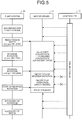
- FIG. 5 is a diagram illustrating a process flow for a motor drive controlling apparatus in a reference example.
- a motor driver 13 (see FIG. 6 ) outputs a drive signal to a motor 11 (see FIG. 6 ) to drive the motor 11.
- a drive signal is generated based on the 120-degree conduction method or the 180-degree conduction method in the motor driver 13 and output to the motor 11.
- a controller 12 (see FIG. 6 ) outputs a drive control signal to the motor driver 13 to execute a variety of control of the motor driver 13. For example, a speed command is transmitted to the motor driver 13 based on a speed command signal that is a command from a user and an encoder signal (see FIG. 6 ) that is output from an encoder 14 to control a rotational speed of the motor 11.
- the motor driver 13 starts an operation to switch a conduction method from 180-degree conduction to 120-degree conduction as described above.
- the motor driver 13 detects it and then the motor driver 13 starts a protective operation to protect the motor 11.
- a protective operation to protect the motor 11 is, for example, a short brake that stops rotation of the motor 11. Then, as rotation of the motor 11 is stopped or is at an extremely low speed that is regarded as stopping due to such a protective operation, the protective operation is released so that rotation of the motor 11 is recovered. On the other hand, even in a case where the controller 12 provides a speed command to the motor driver 13 during a protective operation that is executed by such a motor driver 13, it may be impossible to drive the motor device 10.
- the controller 12 in a motor drive controlling apparatus is provided to have a configuration that will be described below, so that it is possible to drive the motor 11 continuously even in a case where the motor 11 is reversed by an external factor before a conduction method is switched from the 180-degree conduction method to the 120-degree conduction method.
- FIG. 6 is a block diagram illustrating a configuration example of the motor device 10 as illustrated in FIG. 2 .
- the motor device 10 has a motor 11, a controller 12, a motor driver 13, an encoder 14 (an example of a position detector), and a hall element 15 (an example of a magnetic sensor).
- the motor 11 is connected to the pump system 30 through the speed reducer 20.
- the motor 11 is, for example, a three-phase brushless DC motor.
- the motor 11 is driven and controlled by a motor drive controlling apparatus that includes the controller 12 and the motor driver 13. Additionally, a motor drive controlling apparatus may include the encoder 14 and the hall element 15.
- the controller 12 is connected to a speed command signal generator 100 and a rotational direction signal generator 110 that are external devices.
- the controller 12 is composed of, for example, a microprocessor (Micro-Processing Unit: MPU).
- MPU Micro-Processing Unit
- a speed command signal from the speed command signal generator 100 is input to the controller 12 and further a rotational direction signal from the rotational direction signal generator 110 is input thereto, so that a drive control signal is generated based on such a speed command signal and a rotational direction signal.
- Such a speed command signal is a signal that is generated by the speed command signal generator 100 and command information that specifies a target rotational speed of the motor 11.
- a speed command signal is a pulsed signal where a count number is a target rotational step number and a count number per unit time is a target rotational speed.
- the speed command signal generator 100 generates, and outputs to the controller 12, a clock signal with a frequency dependent on a target rotational speed as a speed command signal due to, for example, a Pulse Frequency Modulation (PFM).
- PFM Pulse Frequency Modulation
- a rotational direction signal from the rotational direction signal generator 110 is input to the controller 12, so that a rotational direction of the motor 11 is controlled based on such a rotational direction signal.
- a rotational direction signal is command information that specifies a target rotational direction (that will also be called a "normal direction") of the motor 11.
- a rotational direction signal is a digital signal with a value that is different between a case where a target rotational direction is a clockwise (CW) direction and a case where it is a counterclockwise (CCW) direction.
- the controller 12 generates, as a drive control signal, a pulse width modulation (PWM) signal for rotating the motor 11 at a rotational speed that corresponds to a clock signal due to, for example, PWM.
- a drive control signal includes a control signal for rotating the motor 11 in a rotational direction that is based on a rotational direction signal, as well as a PWM signal.
- the motor driver 13 is connected to a direct-current power source DC and generates, and outputs to the motor 11, a drive signal due to input of a drive control signal that is generated by the controller 12.
- the motor driver 13 has, for example, an inverter circuit and a pre-drive circuit that is an analogue integrated circuit.
- An inverter circuit outputs a drive signal to the motor 11 based on an output signal that is output from a pre-drive circuit and executes conduction for three armature coils that are included by the motor 11.
- An inverter circuit is configured, for example, in such a manner that pairs of series circuits of two switch elements that are provided on both ends of the direct current power source DC are arranged for respective phases (a U-phase, a V-phase, and a W-phase) of three armature coils, respectively. Then, in each pair of such two switch elements, a terminal for each phase of the motor 11 is connected to a connection point between both switch elements.
- a pre-drive circuit generates, and outputs to an inverter circuit, an output signal for driving the inverter circuit based on a drive control signal that is input from the controller 12.
- Such an output signal is, for example, six kinds of switching signals that correspond to respective switch elements of an inverter circuit.
- Such output signals are output to an inverter circuit, so that a switch element that corresponds to each output signal executes an on/off operation and a drive signal is output to the motor 11, so as to supply electric power to each phase for the motor 11.
- a switching signal that is output to an inverter circuit is output at timing that is mutually different between the 120-degree conduction method and the 180-degree conduction method. Therefore, in an embodiment, a conduction method for the motor 11 is controlled in a pre-drive circuit of the motor driver 13.
- the encoder 14 is an example of a position detector that detects a rotational position of the motor 11 (rotor 32).
- the encoder 14 outputs a pulsed signal dependent on a speed command signal (clock signal) and outputs, to the controller 12, a detection signal (encoder signal) that is based on a count number of such a pulsed signal.
- the encoder 14 alternately outputs a signal from an A-phase and a signal from a B-phase with a phase difference from such an A-phase being approximately 90 degrees, respectively, in a case where the motor 11 rotates.
- a measurement unit 41 (see FIG. 7 ) that is included by the controller 12 counts, due to a counter, a rise/fall state change of an output waveform for an A-phase and a rise/fall state change of an output waveform for a B-phase, so that a rotational step number, a rotational direction, and a rotational speed are measured in practice.
- the hall element 15 is an example of a magnetic sensor that detects a position of a magnetic pole in the motor 11 (rotor 32) and outputs a positional signal (hall signal) that is based on a result of such detection to a pre-drive circuit of the motor driver 13.
- a pre-drive circuit adjusts timing when an on/off operation of each switch element of an inverter circuit is switched, based on a received hall signal.
- a pre-drive circuit detects a rotational speed of the motor 11 based on a state change of a received hall signal and switches a conduction method for the motor 11.
- a hall integrated circuit (hall IC) may be used instead of the hall element 15.
- the controller 12 generates, and outputs to the motor driver 13, a drive control signal (PWM signal) based on a speed command signal (clock signal) and an encoder signal that is output by the encoder 14.
- the controller 12 compares a count number of a clock signal (target rotational step number) and a count number of an encoder signal (actual rotational step number) while the motor 11 rotates, due to, for example, input of the clock signal.
- the controller 12 After a ratio between count numbers of a clock signal and an encoder signal is adjusted, the controller 12 generates, and outputs to the motor driver 13, in a case where both count numbers are different, a PWM signal with a changed duty ratio in such a manner that both count numbers equal to each other. Additionally, the controller 12 may execute control to maintain a rotational speed of the motor 11 by using a signal that is output by the hall element 15, instead of an encoder signal that is output by the encoder 14, while the motor 11 rotates due to input of a clock signal.
- the above-mentioned protective function that protects the motor 11 in a case where the motor 11 is reversely rotated by a load that is caused by an external factor is provided to a pre-drive circuit of the motor driver 13.
- a pre-drive circuit detects an actual rotational direction and rotational speed of the motor 11 based on a hall signal transmitted from the hall element 15.
- a pre-drive circuit executes a protective operation that protects the motor 11.
- the controller 12 in a case where the controller 12 detects rotation of the motor 11 in a reverse direction due to an encoder signal from the encoder 14, the controller 12 outputs, to the motor driver 13, a conduction method switching signal that forcibly restarts the motor driver 13 with the 120-degree conduction method, before the above-mentioned protective operation is executed.
- a resolution of the encoder 14 is higher than a resolution of the hall element 15.
- FIG. 7 is a block diagram illustrating a configuration example of the controller 12 according to an embodiment.
- the controller 12 has a measurement unit 41, a transmitting unit 42, and a storage unit 50.
- the storage unit 50 stores target rotational direction information 51 and count threshold information 52. Additionally, the transmitting unit 42 includes a timer.
- the measurement unit 41 detects, based on an encoder signal (detection signal), a time point when rotation of the motor 11 is switched to a reverse direction of a target rotational direction that is based on a rotational direction signal from the rotational direction signal generator 110, by an external factor, during input of a speed command signal from the speed command signal generator 100, and measures a movement amount in the reverse direction from a rotational position of the motor 11 at a time of switching, based on the encoder signal. Then, in a case where a movement amount is a predetermined threshold or more, the transmitting unit 42 transmits, to the motor driver 13, a switching signal that switches a conduction method for the motor driver 13 from 180-degree conduction to 120-degree conduction. Additionally, the measurement unit 41 counts a count value that corresponds to a movement amount of the motor 11 in a reverse direction and the transmitting unit 42 transmits a switching signal to the motor driver 13 in a case where a count value is a specified value.
- an encoder signal detection signal
- the storage unit 50 receives a rotational direction signal from the rotational direction signal generator 110 and stores target rotational direction information 51 that is information on a target rotational direction (CW direction or CCW direction) of the motor 11.
- the measurement unit 41 measures a reverse count that counts a movement amount of the motor 11 in a reverse direction, based on such target rotational direction information 51 and an A-phase encoder signal and a B-phase encoder signal from the encoder 14. A measurement method for such a reverse count will be described later.
- the transmitting unit 42 compares a reverse count that is measured by the measurement unit 41 and a count threshold (an example of a specified value) that is stored in the count threshold information 52 of the storage unit 50. Additionally, such a count threshold is an example of a predetermined threshold for a movement amount of the motor 11 in a reverse direction. Then, in a case where a reverse count is a count threshold or more, the transmitting unit 42 transmits the above-mentioned conduction method switching signal (an example of a switching signal) to the motor driver 13.
- a count threshold an example of a specified value
- FIG. 8 is a diagram illustrating a process flow for a motor drive controlling apparatus according to an embodiment.
- the motor driver 13 starts an operation to switch a conduction method from 180-degree conduction to 120-degree conduction.
- the controller 12 transmits a reset signal (an example of a switching signal) to the motor driver 13. Then, the motor driver 13 is forcibly restarted with 120-degree conduction by such a reset signal, so that it is possible to stop reverse rotation of the motor 11 without starting a protective operation and recover rotation in a normal direction (that will also be called normal rotation below).
- a reset signal an example of a switching signal
- FIG. 9 is a timing diagram illustrating an example of a relationship between respective signal elements in a motor drive controlling apparatus according to an embodiment. Additionally, in an example as illustrated in FIG. 9 , a case is indicated where a target rotational direction that is a command for the motor 11 due to a rotational direction signal is a CCW direction.
- a target rotational direction of the motor 11 is a CW direction
- "0" is first output as a value of an A-phase encoder signal
- "1” is then output as a value of a B-phase encoder signal
- "1” is then output as a value of the A-phase encoder signal.
- "0" is output as a value of a B-phase encoder signal
- an A-phase encoder signal and the B-phase encoder signal are respectively and alternately output in such a predetermined order.
- encoder signals that are output respectively and alternatively (an A-phase encoder signal and a B-phase encoder signal) are output depending on a speed command signal (clock signal). Furthermore, in an example as illustrated in FIG. 9 , the motor 11 is herein driven with the 180-degree conduction method.
- an encoder signal that is output from the encoder 14 is delayed with respect to a clock signal.
- an encoder signal is output in an order that is different from a predetermined one.
- the measurement unit 41 of the controller 12 further adds one count to a reverse count so as to change the reverse count from "1" to "2". Additionally, a specific count method for a reverse count in the measurement unit 41 will be described later.
- the transmitting unit 42 of the controller 12 transmits a reset signal to the motor driver 13 as a reverse count is "2".
- the motor driver 13 is forcibly restarted at time T2 and a conduction method is switched from the 180-degree conduction method to the 120-degree conduction method.
- Such a reset signal is intermittently transmitted for a predetermined period of time (for example, until time T 3 ). Additionally, a specific transmission method for such a reset signal will be described later.
- an increase in a rotational speed in a reverse direction is stopped at time T4 and the motor 11 is reversed from reverse rotation to normal rotation at time T5 to recover the normal rotation.
- the transmitting unit 42 stops transmitting of a reset signal.
- a rotational speed of the motor 11 is a predetermined rotational speed or more at time T6
- the motor driver 13 switches a conduction method from the 120-degree conduction method to the 180-degree conduction method.
- a predetermined rotational speed is, for example, V2 rpm in an example as illustrated in FIG. 9 .
- a setting value of a count threshold is "2" or more.
- a rotational direction fluctuates as the motor 11 rotates at an extremely low speed, that is, a so-called chattering phenomenon occurs, and it is possible to prevent sensitive forcible starting of the motor driver 13 even if a reverse count is "1".
- FIG. 10 is a flowchart illustrating a measurement process for a reverse count according to an embodiment
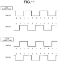
- FIG. 11 is a schematic diagram illustrating output states of an encoder signal in a CW direction and a CCW direction according to an embodiment. Additionally, a measurement process for a reverse count as illustrated in FIG. 10 is executed every time the measurement unit 41 receives a state change of an A-phase encoder signal or a B-phase encoder signal.
- the measurement unit 41 first determines whether a current value of an A-phase encoder signal is different from a current value of a B-phase encoder signal, that is, whether or not the current value of the A-phase encoder signal is "1" and the current value of the B-phase encoder signal is "0” or the current value of the A-phase encoder signal is "0” and the current value of the B-phase encoder signal is "1" (step S101), and in a case where such a condition is met (step S101, Yes), whether the current value of the A-phase encoder signal is equal to a value of the A-phase encoder signal at a time of a previous process is determined (step S102).
- the measurement unit 41 determines, in a case where a current value of an A-phase encoder signal is equal to a value of the A-phase encoder signal at a time of a previous process (step S102, Yes), whether or not a target rotational direction is not a CW direction based on the target rotational direction information 51 (step S103). Then, in a case where a target rotational direction is not a CW direction (step S103, Yes), 1 is added to a reverse count (step S104) and such a process is ended.
- a rotational direction of the motor 11 is a CW direction as illustrated in FIG. 11 .
- a target rotational direction is a CCW direction, so that 1 is added to a reverse count.
- step S105 determines whether or not a reverse count is more than 0 (step S105).
- step S105 determines whether or not a reverse count is more than 0 (step S105).
- step S105 Yes
- 1 is subtracted from the reverse count (step S106) and such a process is ended, or otherwise (step S105, No)
- step S105, No such a process is ended with no change.
- step S102 determines whether or not a target rotational direction is not a CCW direction based on the target rotational direction information 51 (step S107). Then, in a case where a target rotational direction is not a CCW direction (step S107, Yes), 1 is added to a reverse count (step S108) and such a process is ended.
- a rotational direction of the motor 11 is a CCW direction as illustrated in FIG. 11 .
- a target rotational direction is a CW direction, so that 1 is added to a reverse count.
- step S109 determines whether or not a reverse count is more than 0 (step S109).
- a reverse count is more than 0 (step S109, Yes)
- 1 is subtracted from a reverse count (step S110) and such a process is ended, or otherwise (step S109, No), such a process is ended with no change.
- the measurement unit 41 determines whether or not a current value of an A-phase encoder signal is not equal to a value of the A-phase encoder signal at a time of a previous process (step S111).
- the measurement unit 41 determines whether or not a target rotational direction is not a CW direction based on the target rotational direction information 51 (step S112) in a case where a current value of an A-phase encoder signal is not equal to a value of the A-phase encoder signal at a time of a previous process (step S111, Yes). Then, in a case where a target rotational direction is not a CW direction (step S112, Yes), 1 is added to a reverse count (step S113) and such a process is ended.
- a rotational direction of the motor 11 is a CW direction as illustrated in FIG. 11 .
- a target rotational direction is a CCW direction, so that 1 is added to a reverse count.
- step S112 determines whether or not a reverse count is more than 0 (step S114).
- step S114 determines whether or not a reverse count is more than 0 (step S114).
- step S114 Yes
- 1 is subtracted from the reverse count (step S115) and such a process is ended, or otherwise (step S114, No)
- step S114, No such a process is ended with no change.
- step S111 determines whether or not a target rotational direction is not a CCW direction based on the target rotational direction information 51 (step S116). Then, in a case where a target rotational direction is not a CCW direction (step S116, Yes), 1 is added to a reverse count (step S117) and such a process is ended.
- a rotational direction of the motor 11 is a CCW direction as illustrated in FIG. 11 .
- a target rotational direction is a CW direction, so that 1 is added to a reverse count.
- step S116 determines whether or not a reverse count is more than 0 (step S118).
- a reverse count is more than 0 (step S118, Yes)
- 1 is subtracted from a reverse count (step S119) and such a process is ended, or otherwise (step S118, No) such a process is ended with no change.
- a reverse count is measured based on an encoder signal that is output from the encoder 14 that has a resolution that is higher than that of the hall element 15, so that it is possible to detect reversal of the motor 11 quickly after the motor 11 is reversed.
- FIG. 12 is a flowchart illustrating a switching process for a conduction method (a transmission process for a reset signal) according to an embodiment. Additionally, a transmission process for a reset signal as illustrated in FIG. 12 is executed at each predetermined time interval (for example, 500 ( ⁇ s)).
- a predetermined time interval for example, 500 ( ⁇ s)
- the transmitting unit 42 first determines whether or not a reverse count is 2 or more (that is, a count threshold or more) (step S201), and in a case where the reverse count is 2 or more (step S201, Yes), whether or not a value of a conduction switching waiting timer is "0" is determined (step S202). Additionally, in a case where a determination condition at step S201 is not satisfied (step S201, No), such a process is ended.
- the transmitting unit 42 determines whether or not a value of a conduction method switching signal transmitting timer is "0" (step S203). Then, in a case where a value of a conduction method switching signal transmitting timer is "0" (step S203, Yes), the transmitting unit 42 transmits a reset signal to the motor driver 13 (step S204), and sets the conduction method switching signal transmitting timer at a transmitting time of a reset signal (step S205), and such a process is ended.
- the transmitting unit 42 subtracts 1 from a value of a conduction method switching signal transmitting timer (step S206) and determines whether or not a value of the conduction method switching signal transmitting timer is "0" (step S207).
- step S207, Yes the transmitting unit 42 stops transmitting of a reset signal (step S208), and sets a conduction switching waiting timer at a waiting time for once waiting transmitting of a reset signal (step S209), and such a process is ended. Additionally, in a case where a determination condition at step S207 is not satisfied (step S207, No), such a process is ended with no change.
- step S210 the transmitting unit 42 subtracts 1 from a value of a conduction switching waiting timer (step S210) and such a process is ended.
- a reverse count is continuously 2 or more (that is, a count threshold or more) due to a transmission process for a conduction method switching signal as already described
- the transmitting unit 42 transmits a conduction method switching signal for a predetermined on-time (that corresponds to a conduction switching signal transmitting timer), subsequently stops transmitting for a predetermined off-time (that corresponds to a conduction switching waiting timer), and subsequently repeat a process that transmits a conduction method switching signal for a predetermined on-time again.
- the transmitting unit 42 transmits a conduction method switching signal to the motor driver 13 and subsequently a reverse count is continuously a count threshold or more, it is possible to transmit such a conduction method switching signal to the motor driver 13 intermittently (regularly).
- the motor driver 13 in a case where a reverse count is measured based on an encoder signal from the encoder 14 and such a reverse count is a predetermined count threshold or more, the motor driver 13 is forcibly restarted, so that it is possible to drive the motor 11 continuously even in a case where the motor 11 is reversed by an external factor before a conduction method is switched from the 180-degree conduction method to the 120-degree conduction method.
- speed command signal generator 100 and the rotational direction signal generator 110 are external devices.
- at least one of the speed command signal generator 100 and the rotational direction signal generator 110 may be placed in an interior of the motor device 10 as a motor drive controlling apparatus.
- a case where the motor 11 is a brushless DC motor has been described in the embodiment as described above.
- a position detector (encoder 14) that outputs a pulsed signal dependent on a clock signal is arranged and it is possible to apply a motor drive controlling method as described in an embodiment to a motor capable of rotational speed control that is executed by a clock signal.
- the blood pump 1 that pumps blood in the tube 2 has been described as an example of a tube pump in the embodiment as described above, it is also possible to apply a motor drive controlling method as described in an embodiment to, for example, a tube pump that pumps physiological saline or any other liquid.
- a position detector is not limited to an encoder and a magnetic sensor is also not limited to a hall element. Any combination of a position detector and a magnetic sensor is allowed as long as a resolution of such a position detector is higher than a resolution of such a magnetic sensor.
- a motor drive controlling apparatus includes the controller 12 that generates and outputs a drive control signal in response to input of a speed command signal and a rotational direction signal, the motor driver 13 that generates a drive signal and outputs the generated drive signal to the motor 11, in response to input of a drive control signal, and the position detector (encoder 14) that detects a rotational position of the motor 11 and outputs a detection signal (encoder signal) that is based on such a detection result. Furthermore, the motor driver 13 provides 120-degree conduction as a conduction method from a start of rotation of the motor 11 to a predetermined rotational speed or provides 180-degree conduction as a conduction method for a predetermined rotational speed or more.
- the controller 12 has the measurement unit 41 that detects, based on a detection signal (encoder signal), a time point when rotation of the motor 11 is switched to a reverse direction of a target rotational direction that is based on a rotational direction signal by an external factor during input of a speed command signal, and measures a movement amount in a reverse direction from a rotational position of the motor 11 at a time of switching, based on a detection signal (encoder signal), and the transmitting unit 42 that transmits, to the motor driver 13, a switching signal (conduction method switching signal) that switches a conduction method for the motor driver 13 from 180-degree conduction to 120-degree conduction in a case where the movement amount is a predetermined threshold or more.
- a switching signal conduction method switching signal
- the transmitting unit 42 transmits a switching signal (conduction method switching signal) to the motor driver 13 intermittently in a case where the measurement unit 41 detects that the motor 11 rotates in a reverse direction due to an external factor after a switching signal (conduction method switching signal) is transmitted to the motor driver 13. Thereby, it is possible to restart the motor driver 13 reliably.
- the transmitting unit 42 stops transmitting of a switching signal (conduction method switching signal) in a case where the measurement unit 41 detects that the motor 11 returns to a target rotational direction. Thereby, it is possible to prevent the motor driver 13 from being unnecessarily restarted in a case where a reverse phenomenon of the motor 11 is removed.
- the measurement unit 41 counts a count value (reverse count) that corresponds to a movement amount and the transmitting unit 42 transmits a switching signal (conduction method switching signal) to the motor driver 13 in a case where such a count value (reverse count) is a specified value (count threshold).
- a count threshold is set at "2", so that it is possible to avoid determining a chattering phenomenon where, as the motor 11 rotates at an extremely low speed, a rotational direction fluctuates, to be reverse rotation that is caused by an external factor.
- a motor drive controlling apparatus further includes a magnetic sensor (hall element) that detects a position of a magnetic pole for conduction switching of the motor 11 and outputs a positional signal (hall signal) that is based on a result of such detection. Furthermore, the motor driver 13 executes a protective operation that stops generation of a drive signal in a case where detection is executed based on a positional signal (hall signal) in such a manner that the motor 11 starts rotation in a reverse direction due to an external factor.
- a magnetic sensor (hall element) that detects a position of a magnetic pole for conduction switching of the motor 11 and outputs a positional signal (hall signal) that is based on a result of such detection.
- the motor driver 13 executes a protective operation that stops generation of a drive signal in a case where detection is executed based on a positional signal (hall signal) in such a manner that the motor 11 starts rotation in a reverse direction due to an external factor.
- the transmitting unit 42 transmits a switching signal (conduction method switching signal) to the motor driver 13 before detection is executed based on a positional signal (hall signal) in such a manner that the motor 11 starts rotation in a reverse direction in a case where the motor 11 starts rotation in a reverse direction due to an external factor.
- a switching signal conduction method switching signal
- the transmitting unit 42 transmits a switching signal (conduction method switching signal) to the motor driver 13 before detection is executed based on a positional signal (hall signal) in such a manner that the motor 11 starts rotation in a reverse direction in a case where the motor 11 starts rotation in a reverse direction due to an external factor.
- a resolution of a position detector is higher than a resolution of a magnetic sensor (hall element).
- a tube pump includes the motor 11, the rollers 34a, 34b that are rotated by drive of the motor 11, and press the tube 2 to deliver liquid contained in the tube 2, and a motor drive controlling apparatus that executes a motor drive controlling method as described above.
- a motor drive controlling apparatus that executes a motor drive controlling method as described above.
Landscapes
- Health & Medical Sciences (AREA)
- Engineering & Computer Science (AREA)
- Heart & Thoracic Surgery (AREA)
- Cardiology (AREA)
- Mechanical Engineering (AREA)
- General Health & Medical Sciences (AREA)
- Hematology (AREA)
- Life Sciences & Earth Sciences (AREA)
- Animal Behavior & Ethology (AREA)
- Anesthesiology (AREA)
- Public Health (AREA)
- Veterinary Medicine (AREA)
- Biomedical Technology (AREA)
- Power Engineering (AREA)
- General Engineering & Computer Science (AREA)
- Urology & Nephrology (AREA)
- Pulmonology (AREA)
- Emergency Medicine (AREA)
- Vascular Medicine (AREA)
- Control Of Motors That Do Not Use Commutators (AREA)
- External Artificial Organs (AREA)
- Control Of Electric Motors In General (AREA)
Abstract
Description
- The present invention relates to a motor drive controlling apparatus, a motor drive controlling method, and a tube pump.
- Conventionally, there has been known a tube pump of related art as a pump apparatus. The tube pump delivers liquid contained in a tube by causing a motor to rotate rollers while pressing and flattening the tube. A tube pump is used in a medical apparatus, and there has been known a pump apparatus (blood pump) for artificial dialysis in which a brushless direct current (DC) motor rotates a rotor having rollers, for example.
- There exist, for example, a 120-degree conduction method and a 180-degree conduction method among conduction methods of this brushless DC motor used in the tube pump. Commonly, this brushless DC motor to be operated in the 180-degree conduction method starts to rotate in the 120-degree conduction method, and switches to the low-noise and low-vibration 180-degree conduction method in accordance with an actual rotational speed of the motor. When an external factor causes the actual rotational speed of the motor to fall below a predetermined rotational speed, the conduction method is switched from the 180-degree conduction method to the 120-degree conduction method so as to sustain the control of the motor (see Japanese Laid-open Patent Publication No.
10-290831 - However, a brushless DC motor that is used for a conventional tube pump needs some time to switch a conduction method from the 180-degree conduction method to the 120-degree conduction method. Then, there is a problem in that, in a case where a motor is reversed by an external factor before a conduction method is switched, as such reversal is detected, a protective operation (for example, a short brake) is added thereto until the motor is stopped or a reverse speed thereof is an extremely low speed that is regarded as stopping, so that it may be impossible to drive the motor until a reverse phenomenon is removed and the protective operation is released.
- The present disclosure is provided by taking the above into consideration and aims to provide a motor drive controlling apparatus, a motor drive controlling method, and a tube pump that are capable of driving a motor continuously even in a case where such a motor is reversed by an external factor.
- A motor drive controlling apparatus includes: a controller, a motor driver, and a position detector. The controller generates and outputs a drive control signal in response to an input of a speed command signal and a rotational direction signal. The motor driver generates a drive signal and outputs the generated drive signal to a motor, in response to an input of the drive control signal. The position detector that detects a rotational position of the motor and outputs a detection signal that is based on a detection result. The motor driver provides 120-degree conduction as a conduction method from a start of rotation of the motor to a predetermined rotational speed or provides 180-degree conduction as a conduction method for the predetermined rotational speed or more. The controller has: a measurement unit that detects a time point when rotation of the motor is switched to a reverse direction of a target rotational direction that is based on the rotational direction signal by an external factor during input of the speed command signal, based on the detection signal, and measures a movement amount in the reverse direction from a rotational position of the motor at a time point of the switching, based on the detection signal; and a transmitting unit that transmits, to the motor driver, a switching signal that switches a conduction method for the motor driver from the 180-degree conduction to the 120-degree conduction in a case where the movement amount is a predetermined threshold or more.
- The above and other objects, features, advantages and technical and industrial significance of this invention will be better understood by reading the following detailed description of presently preferred embodiments of the invention, when considered in connection with the accompanying drawings.
-
-
FIG. 1 is a diagram illustrating a configuration example of an artificial dialysis system that assembles a blood pump according to an embodiment. -
FIG. 2 is a first diagram for illustrating a blood pump as illustrated inFIG. 1 . -
FIG. 3 is a second diagram for illustrating a blood pump as illustrated inFIG. 1 . -
FIG. 4 is a diagram for illustrating an example of a switching operation for a conduction method in a motor device according to an embodiment. -
FIG. 5 is a diagram illustrating a process flow for a motor drive controlling apparatus in a reference example. -
FIG. 6 is a block diagram illustrating a configuration example of a motor device as illustrated inFIG. 2 . -
FIG. 7 is a block diagram illustrating a configuration example of a controller according to an embodiment. -
FIG. 8 is a diagram illustrating a process flow for a motor drive controlling apparatus according to an embodiment. -
FIG. 9 is a timing diagram illustrating an example of a relationship between respective signal elements in a motor drive controlling apparatus according to an embodiment. -
FIG. 10 is flowchart illustrating a measurement process for a reverse count according to an embodiment. -
FIG. 11 is a schematic diagram illustrating output states of an encoder signal in a CW direction and a CCW direction according to an embodiment. -
FIG. 12 is a flowchart illustrating a transmission process for a reset signal according to an embodiment. - Hereinafter, a motor drive controlling apparatus, a motor drive controlling method, and a tube pump according to an embodiment will be described with reference to the drawings. Additionally, a relationship between numerical values of respective elements, scales of respective elements, or the like in the drawings may be different from actual ones. Furthermore, the drawings may include parts where relationships between mutual numerical values or scales are different from one another.
- Hereinafter, a case will be described where a tube pump that uses a motor drive controlling apparatus according to an embodiment is a blood pump of an artificial dialysis system.
FIG. 1 is a diagram illustrating a configuration example of an artificial dialysis system that assembles a blood pump according to an embodiment. - The artificial dialysis system as illustrated in
FIG. 1 has a blood pump 1 (one example of tube pump), adialyzer 3, and adialysis fluid supplier 4. Theblood pump 1 delivers blood of a patient P to thedialyzer 3 through a tube 2 (blood removal). - Such a
dialyzer 3 executes a process of removing wastes, maintaining electrolytes, and maintaining a water amount for blood of such a patient P due to a semipermeable membrane and a dialysis fluid that is supplied from thedialysis fluid supplier 4. Furthermore, theblood pump 1 returns blood that is processed by thedialyzer 3 to such a patient P through the tube 2 (blood return). -
FIG. 2 andFIG. 3 are diagrams for illustrating theblood pump 1 as illustrated inFIG. 1 . As illustrated inFIG. 2 , theblood pump 1 has amotor device 10, aspeed reducer 20, and apump system 30. Additionally,FIG. 2 is a diagram of theblood pump 1 as illustrated inFIG. 1 that is viewed from a side surface side andFIG. 3 is a diagram of theblood pump 1 as illustrated inFIG. 1 that is viewed from a side facing apump system 30. - In
FIG. 2 , themotor device 10 is a drive source that supplies rotational drive force to a rotor 32 (seeFIG. 3 ) of thepump system 30 through thespeed reducer 20 and assembles a motor 11 (seeFIG. 6 ) as described later. Thespeed reducer 20 is connected to a rotating shaft of the motor device 10 (motor 11) and reduces a rotational speed of themotor 11 with a predetermined reduction ratio. Thepump system 30 is connected to a rotating shaft (output shaft) of thespeed reducer 20. - The
pump system 30 has ahousing 31, arotor 32, aroller support 33, aroller 34a, and aroller 34b as illustrated inFIG. 3 . Thehousing 31 forms an internal space for accommodating thetube 2 and therotor 32. Thetube 2 is arranged or provided along an arc-shaped inner circumferential wall surface that is possessed by thehousing 31. Therotor 32 is connected to a rotating shaft (output shaft) of thespeed reducer 20. - The
roller support 33 is connected to therotor 32 and rotates with rotation of therotor 32. Theroller 34a and theroller 34b are attached to both ends of theroller support 33, respectively. The roller support 33 rotatably supports theroller 34a and theroller 34b that press thetube 2. - The
roller 34a and theroller 34b rotate with rotation of theroller support 33. That is, theroller 34a and theroller 34b rotate when driven by the motor device 10 (motor 11) to press thetube 2 that is arranged or provided along an inner circumferential wall surface of thehousing 31 and deliver the liquid (blood) in thetube 2. -
FIG. 4 is a diagram for illustrating an example of a switching operation for a conduction method in themotor device 10 according to an embodiment. As illustrated inFIG. 4 , a 120-degree conduction method (that will also be called 120-degree conduction below) and the 180-degree conduction method (that will also be called 180-degree conduction below) are provided as conduction methods for themotor 11 in themotor device 10. - 120-degree conduction is a conduction method that is used as the
motor 11 is driven at a low rotational speed (for example, V1 - V2 rpm). 180-degree conduction is a conduction method that is used as themotor 11 is driven at a medium or high rotational speed (for example, V3 rpm or more). In the following embodiment, a case where V1- V2 rpm is less than 100 rpm and V3 rpm is more than 100 rpm will be described as an example. - 120-degree conduction has an advantage of a large torque at a low rotational speed while having a disadvantage of large noise and vibration at a medium or high rotational speed. On the other hand, 180-degree conduction has a disadvantage of a small torque at a low rotational speed as compared with 120-degree conduction while having an advantage of small noise and vibration at a medium or high rotational speed.
- Hence, in an embodiment, control is executed in such a manner that conduction is 120-degree conduction at a time of restarting of the
motor 11 and is switched to 180-degree conduction as an actual rotational speed is a predetermined rotational speed (for example, V2 rpm) or more. - Furthermore, in an example as illustrated in
FIG. 4 , the following control is executed in a case where themotor 11 rotates at a low rotational speed (for example, 100 rpm). First, as a Pulse Width Modulation (PWM) duty ratio (that will also be called a duty ratio below) of themotor 11 is increased by 120-degree conduction, rotation of themotor 11 starts at D2% and a rotational speed thereof is V1 rpm (step S1). - Subsequently, as the duty ratio is increased and a rotational speed is V2 rpm or more at D3% (step S2), a conduction method is switched from 120-degree conduction to 180-degree conduction (step S3). Accordingly, a rotational speed of the
motor 11 rapidly increases from V2 rpm to V4 rpm and exceeds a target rotational speed (100 rpm). - Then, as a duty ratio is decreased while keeping 180-degree conduction, a rotational speed is V3 rpm at D1% (step S4). Subsequently, as a duty ratio is decreased, a rotational speed is reduced in a free state where the
motor 11 is not capable of rotating due to a lack of torque, and as a rotational speed is V2 rpm or less, a conduction method is switched from 180-degree conduction to 120-degree conduction (step S5). - Then, as a rotational speed is 100 rpm or less, a duty ratio increases but a free state where the
motor 11 is not capable of rotating continues (Steps S4 to S5 and Steps S5 to S1), and themotor 11 restarts rotation with 120-degree conduction at D2% again (step Si). Thus, themotor 11 repeats steps of 120-degree conduction (Steps S1 to S2), 180-degree conduction (Steps S3 to S4), and free one (Steps S4 to S5 and Steps S5 to S1), so that it is possible for an average of a rotational speed of themotor 11 to be a target rotational speed (100 rpm). - Additionally, the
motor 11 in an embodiment is used to be further decelerated by thespeed reducer 20 as described above, and hence, the above-mentioned steps are repeated so that there is not a problem in practice even in a case where a rotational speed varies microscopically. - Next, a problem in such a
motor device 10 will be described with reference toFIG. 5. FIG. 5 is a diagram illustrating a process flow for a motor drive controlling apparatus in a reference example. - As illustrated in
FIG. 5 , a motor driver 13 (seeFIG. 6 ) outputs a drive signal to a motor 11 (seeFIG. 6 ) to drive themotor 11. Such a drive signal is generated based on the 120-degree conduction method or the 180-degree conduction method in themotor driver 13 and output to themotor 11. - A controller 12 (see
FIG. 6 ) outputs a drive control signal to themotor driver 13 to execute a variety of control of themotor driver 13. For example, a speed command is transmitted to themotor driver 13 based on a speed command signal that is a command from a user and an encoder signal (seeFIG. 6 ) that is output from anencoder 14 to control a rotational speed of themotor 11. - Herein, in a case where a load that is caused by an external factor instantaneously increases for the
pump system 30 during a low speed operation and a rotational speed of themotor 11 is less than a predetermined rotational speed (for example, V2 rpm), themotor driver 13 starts an operation to switch a conduction method from 180-degree conduction to 120-degree conduction as described above. - However, as the load continues to be added before the conduction method is switched to 120-degree conduction and the
motor 11 rotates in a direction opposite to a target rotational direction (0 rpm or less) (that will also be called reverse rotation below) and further such reverse rotation is of a predetermined rotational speed (for example, -V2 rpm) or less, themotor driver 13 detects it and then themotor driver 13 starts a protective operation to protect themotor 11. - That is because, as the
motor 11 reversely rotates with the 180-degree conduction method that generates a drive waveform of a sine wave based on a previous signal from a hall element 15 (seeFIG. 6 ; an example of a magnetic sensor), an order of conduction that is different from previous one is detected, and therefore, it may be impossible to generate a drive waveform. Additionally, it is possible for themotor driver 13 to detect a rotational speed of themotor 11 due to thehall element 15 that is assembled in themotor device 10. - A protective operation to protect the
motor 11 is, for example, a short brake that stops rotation of themotor 11. Then, as rotation of themotor 11 is stopped or is at an extremely low speed that is regarded as stopping due to such a protective operation, the protective operation is released so that rotation of themotor 11 is recovered. On the other hand, even in a case where thecontroller 12 provides a speed command to themotor driver 13 during a protective operation that is executed by such amotor driver 13, it may be impossible to drive themotor device 10. - Hence, the
controller 12 in a motor drive controlling apparatus according to an embodiment is provided to have a configuration that will be described below, so that it is possible to drive themotor 11 continuously even in a case where themotor 11 is reversed by an external factor before a conduction method is switched from the 180-degree conduction method to the 120-degree conduction method. -
FIG. 6 is a block diagram illustrating a configuration example of themotor device 10 as illustrated inFIG. 2 . As illustrated inFIG. 6 , themotor device 10 has amotor 11, acontroller 12, amotor driver 13, an encoder 14 (an example of a position detector), and a hall element 15 (an example of a magnetic sensor). - The
motor 11 is connected to thepump system 30 through thespeed reducer 20. Themotor 11 is, for example, a three-phase brushless DC motor. Themotor 11 is driven and controlled by a motor drive controlling apparatus that includes thecontroller 12 and themotor driver 13. Additionally, a motor drive controlling apparatus may include theencoder 14 and thehall element 15. - The
controller 12 is connected to a speedcommand signal generator 100 and a rotationaldirection signal generator 110 that are external devices. Thecontroller 12 is composed of, for example, a microprocessor (Micro-Processing Unit: MPU). A speed command signal from the speedcommand signal generator 100 is input to thecontroller 12 and further a rotational direction signal from the rotationaldirection signal generator 110 is input thereto, so that a drive control signal is generated based on such a speed command signal and a rotational direction signal. - Such a speed command signal is a signal that is generated by the speed
command signal generator 100 and command information that specifies a target rotational speed of themotor 11. Specifically, a speed command signal is a pulsed signal where a count number is a target rotational step number and a count number per unit time is a target rotational speed. - The speed
command signal generator 100 generates, and outputs to thecontroller 12, a clock signal with a frequency dependent on a target rotational speed as a speed command signal due to, for example, a Pulse Frequency Modulation (PFM). - Furthermore, a rotational direction signal from the rotational
direction signal generator 110 is input to thecontroller 12, so that a rotational direction of themotor 11 is controlled based on such a rotational direction signal. A rotational direction signal is command information that specifies a target rotational direction (that will also be called a "normal direction") of themotor 11. Specifically, a rotational direction signal is a digital signal with a value that is different between a case where a target rotational direction is a clockwise (CW) direction and a case where it is a counterclockwise (CCW) direction. - Then, the
controller 12 generates, as a drive control signal, a pulse width modulation (PWM) signal for rotating themotor 11 at a rotational speed that corresponds to a clock signal due to, for example, PWM. Additionally, such a drive control signal includes a control signal for rotating themotor 11 in a rotational direction that is based on a rotational direction signal, as well as a PWM signal. - The
motor driver 13 is connected to a direct-current power source DC and generates, and outputs to themotor 11, a drive signal due to input of a drive control signal that is generated by thecontroller 12. Themotor driver 13 has, for example, an inverter circuit and a pre-drive circuit that is an analogue integrated circuit. - An inverter circuit outputs a drive signal to the
motor 11 based on an output signal that is output from a pre-drive circuit and executes conduction for three armature coils that are included by themotor 11. An inverter circuit is configured, for example, in such a manner that pairs of series circuits of two switch elements that are provided on both ends of the direct current power source DC are arranged for respective phases (a U-phase, a V-phase, and a W-phase) of three armature coils, respectively. Then, in each pair of such two switch elements, a terminal for each phase of themotor 11 is connected to a connection point between both switch elements. - A pre-drive circuit generates, and outputs to an inverter circuit, an output signal for driving the inverter circuit based on a drive control signal that is input from the
controller 12. Such an output signal is, for example, six kinds of switching signals that correspond to respective switch elements of an inverter circuit. Such output signals are output to an inverter circuit, so that a switch element that corresponds to each output signal executes an on/off operation and a drive signal is output to themotor 11, so as to supply electric power to each phase for themotor 11. - Additionally, a switching signal that is output to an inverter circuit is output at timing that is mutually different between the 120-degree conduction method and the 180-degree conduction method. Therefore, in an embodiment, a conduction method for the
motor 11 is controlled in a pre-drive circuit of themotor driver 13. - The
encoder 14 is an example of a position detector that detects a rotational position of the motor 11 (rotor 32). Theencoder 14 outputs a pulsed signal dependent on a speed command signal (clock signal) and outputs, to thecontroller 12, a detection signal (encoder signal) that is based on a count number of such a pulsed signal. - The
encoder 14 alternately outputs a signal from an A-phase and a signal from a B-phase with a phase difference from such an A-phase being approximately 90 degrees, respectively, in a case where themotor 11 rotates. A measurement unit 41 (seeFIG. 7 ) that is included by thecontroller 12 counts, due to a counter, a rise/fall state change of an output waveform for an A-phase and a rise/fall state change of an output waveform for a B-phase, so that a rotational step number, a rotational direction, and a rotational speed are measured in practice. - The
hall element 15 is an example of a magnetic sensor that detects a position of a magnetic pole in the motor 11 (rotor 32) and outputs a positional signal (hall signal) that is based on a result of such detection to a pre-drive circuit of themotor driver 13. A pre-drive circuit adjusts timing when an on/off operation of each switch element of an inverter circuit is switched, based on a received hall signal. - Furthermore, a pre-drive circuit detects a rotational speed of the
motor 11 based on a state change of a received hall signal and switches a conduction method for themotor 11. Additionally, a hall integrated circuit (hall IC) may be used instead of thehall element 15. - The
controller 12 generates, and outputs to themotor driver 13, a drive control signal (PWM signal) based on a speed command signal (clock signal) and an encoder signal that is output by theencoder 14. Thecontroller 12 compares a count number of a clock signal (target rotational step number) and a count number of an encoder signal (actual rotational step number) while themotor 11 rotates, due to, for example, input of the clock signal. - Then, after a ratio between count numbers of a clock signal and an encoder signal is adjusted, the
controller 12 generates, and outputs to themotor driver 13, in a case where both count numbers are different, a PWM signal with a changed duty ratio in such a manner that both count numbers equal to each other. Additionally, thecontroller 12 may execute control to maintain a rotational speed of themotor 11 by using a signal that is output by thehall element 15, instead of an encoder signal that is output by theencoder 14, while themotor 11 rotates due to input of a clock signal. - Meanwhile, in the
motor device 10, the above-mentioned protective function that protects themotor 11 in a case where themotor 11 is reversely rotated by a load that is caused by an external factor is provided to a pre-drive circuit of themotor driver 13. A pre-drive circuit detects an actual rotational direction and rotational speed of themotor 11 based on a hall signal transmitted from thehall element 15. - Then, in a case where detection is executed based on a hall signal in such a manner that the
motor 11 rotates in a rotational direction (that will also be called a reverse direction below) opposite to a target rotational direction and further rotation in the reverse direction is of a predetermined rotational speed or more (that is, rotation in a normal direction is of a predetermined minus rotational speed or less), a pre-drive circuit executes a protective operation that protects themotor 11. - Herein, in an embodiment, in a case where the
controller 12 detects rotation of themotor 11 in a reverse direction due to an encoder signal from theencoder 14, thecontroller 12 outputs, to themotor driver 13, a conduction method switching signal that forcibly restarts themotor driver 13 with the 120-degree conduction method, before the above-mentioned protective operation is executed. - Thereby, it is possible to prevent the
motor 11 from starting a protective operation even in a case where themotor 11 is reversed by an external factor before a conduction method is switched from the 180-degree conduction method to the 120-degree conduction method. Therefore, according to an embodiment, it is possible to drive themotor 11 continuously. - Furthermore, in an embodiment, a resolution of the
encoder 14 is higher than a resolution of thehall element 15. Thereby, it is possible for thecontroller 12 to detect rotation of themotor 11 in a reverse direction rapidly based on an encoder signal from theencoder 14 before themotor driver 13 starts a protective operation based on a hall signal transmitted from thehall element 15. -
FIG. 7 is a block diagram illustrating a configuration example of thecontroller 12 according to an embodiment. Thecontroller 12 has ameasurement unit 41, a transmittingunit 42, and astorage unit 50. Thestorage unit 50 stores targetrotational direction information 51 andcount threshold information 52. Additionally, the transmittingunit 42 includes a timer. - As described in detail below, the
measurement unit 41 detects, based on an encoder signal (detection signal), a time point when rotation of themotor 11 is switched to a reverse direction of a target rotational direction that is based on a rotational direction signal from the rotationaldirection signal generator 110, by an external factor, during input of a speed command signal from the speedcommand signal generator 100, and measures a movement amount in the reverse direction from a rotational position of themotor 11 at a time of switching, based on the encoder signal. Then, in a case where a movement amount is a predetermined threshold or more, the transmittingunit 42 transmits, to themotor driver 13, a switching signal that switches a conduction method for themotor driver 13 from 180-degree conduction to 120-degree conduction. Additionally, themeasurement unit 41 counts a count value that corresponds to a movement amount of themotor 11 in a reverse direction and the transmittingunit 42 transmits a switching signal to themotor driver 13 in a case where a count value is a specified value. - The
storage unit 50 receives a rotational direction signal from the rotationaldirection signal generator 110 and stores targetrotational direction information 51 that is information on a target rotational direction (CW direction or CCW direction) of themotor 11. Themeasurement unit 41 measures a reverse count that counts a movement amount of themotor 11 in a reverse direction, based on such targetrotational direction information 51 and an A-phase encoder signal and a B-phase encoder signal from theencoder 14. A measurement method for such a reverse count will be described later. - The transmitting
unit 42 compares a reverse count that is measured by themeasurement unit 41 and a count threshold (an example of a specified value) that is stored in thecount threshold information 52 of thestorage unit 50. Additionally, such a count threshold is an example of a predetermined threshold for a movement amount of themotor 11 in a reverse direction. Then, in a case where a reverse count is a count threshold or more, the transmittingunit 42 transmits the above-mentioned conduction method switching signal (an example of a switching signal) to themotor driver 13. -
FIG. 8 is a diagram illustrating a process flow for a motor drive controlling apparatus according to an embodiment. As illustrated inFIG. 8 , in a case where a load that is caused by an external factor instantaneously increases in thepump system 30 during a low speed operation and a rotational speed of themotor 11 is less than a predetermined rotational speed (for example, V2 rpm), themotor driver 13 starts an operation to switch a conduction method from 180-degree conduction to 120-degree conduction. - Herein, in an embodiment, as the
motor 11 reversely rotates (that is, 0 rpm or less) and thecontroller 12 detects such reverse rotation, thecontroller 12 transmits a reset signal (an example of a switching signal) to themotor driver 13. Then, themotor driver 13 is forcibly restarted with 120-degree conduction by such a reset signal, so that it is possible to stop reverse rotation of themotor 11 without starting a protective operation and recover rotation in a normal direction (that will also be called normal rotation below). -
FIG. 9 is a timing diagram illustrating an example of a relationship between respective signal elements in a motor drive controlling apparatus according to an embodiment. Additionally, in an example as illustrated inFIG. 9 , a case is indicated where a target rotational direction that is a command for themotor 11 due to a rotational direction signal is a CCW direction. - Therefore, as illustrated in
FIG. 9 , "0" (Low signal) is first output as a value of a B-phase encoder signal (ENC-B), "1" (High signal) is then output as a value of an A-phase encoder signal (ENC-A), and "1" is then output as a value of the B-phase encoder signal. Subsequently, "0" is output as a value of an A-phase encoder signal, and afterward, the A-phase encoder signal and a B-phase encoder signal are respectively and alternately output in such a predetermined order. - Additionally, in a case where a target rotational direction of the
motor 11 is a CW direction, "0" is first output as a value of an A-phase encoder signal, "1" is then output as a value of a B-phase encoder signal, and "1" is then output as a value of the A-phase encoder signal. Subsequently, "0" is output as a value of a B-phase encoder signal, and afterward, an A-phase encoder signal and the B-phase encoder signal are respectively and alternately output in such a predetermined order. - Then, in a case where the
motor 11 maintains a predetermined rotational speed, encoder signals that are output respectively and alternatively (an A-phase encoder signal and a B-phase encoder signal) are output depending on a speed command signal (clock signal). Furthermore, in an example as illustrated inFIG. 9 , themotor 11 is herein driven with the 180-degree conduction method. - However, as a load that is caused by an external factor increases so that a rotational speed of the
motor 11 is lower than a target rotational speed, an encoder signal that is output from theencoder 14 is delayed with respect to a clock signal. Moreover, as themotor 11 is reversed at a time T1, an encoder signal is output in an order that is different from a predetermined one. - In an example as illustrated in
FIG. 9 , as themotor 11 is reversed after a value "1" of an A-phase encoder signal is output, a value "1" of a B-phase encoder signal that is in a next order is not output but a value "0" of the A-phase encoder signal is output. Thus, as an encoder signal with an order that is different from a predetermined one is output, themeasurement unit 41 of thecontroller 12 adds one count to a reverse count so as to change the reverse count from "0" to "1". - Moreover, as reverse rotation of the
motor 11 is continued, a value "1" of a B-phase encoder signal that indicates that reverse rotation is continued is output after a value "0" of an A-phase encoder signal is output. Accordingly, themeasurement unit 41 of thecontroller 12 further adds one count to a reverse count so as to change the reverse count from "1" to "2". Additionally, a specific count method for a reverse count in themeasurement unit 41 will be described later. - Herein, in a case where a count threshold that is stored in the
storage unit 50 is set at "2", the transmittingunit 42 of thecontroller 12 transmits a reset signal to themotor driver 13 as a reverse count is "2". Thereby, themotor driver 13 is forcibly restarted at time T2 and a conduction method is switched from the 180-degree conduction method to the 120-degree conduction method. - That is, due to such a reset signal, it is possible to drive the
motor 11 continuously without restarting a protective operation that is executed by themotor driver 13. Such a reset signal is intermittently transmitted for a predetermined period of time (for example, until time T3). Additionally, a specific transmission method for such a reset signal will be described later. - Then, in an example as illustrated in
FIG. 9 , an increase in a rotational speed in a reverse direction is stopped at time T4 and themotor 11 is reversed from reverse rotation to normal rotation at time T5 to recover the normal rotation. Herein, in an embodiment, in a case where themeasurement unit 41 detects that themotor 11 returns to a target rotational direction, the transmittingunit 42 stops transmitting of a reset signal. - Moreover, as a rotational speed of the
motor 11 is a predetermined rotational speed or more at time T6, themotor driver 13 switches a conduction method from the 120-degree conduction method to the 180-degree conduction method. Such a predetermined rotational speed is, for example, V2 rpm in an example as illustrated inFIG. 9 . - Additionally, a case where a count threshold is set at "2" has been indicated in an embodiment as described above, a setting value of a count threshold is "2" or more. For example, in a case where a count threshold is set at "2", a rotational direction fluctuates as the
motor 11 rotates at an extremely low speed, that is, a so-called chattering phenomenon occurs, and it is possible to prevent sensitive forcible starting of themotor driver 13 even if a reverse count is "1". - Subsequently, a measurement process for a reverse count will be described by using
FIG. 10 andFIG. 11 .FIG. 10 is a flowchart illustrating a measurement process for a reverse count according to an embodiment andFIG. 11 is a schematic diagram illustrating output states of an encoder signal in a CW direction and a CCW direction according to an embodiment. Additionally, a measurement process for a reverse count as illustrated inFIG. 10 is executed every time themeasurement unit 41 receives a state change of an A-phase encoder signal or a B-phase encoder signal. - As illustrated in
FIG. 10 , themeasurement unit 41 first determines whether a current value of an A-phase encoder signal is different from a current value of a B-phase encoder signal, that is, whether or not the current value of the A-phase encoder signal is "1" and the current value of the B-phase encoder signal is "0" or the current value of the A-phase encoder signal is "0" and the current value of the B-phase encoder signal is "1" (step S101), and in a case where such a condition is met (step S101, Yes), whether the current value of the A-phase encoder signal is equal to a value of the A-phase encoder signal at a time of a previous process is determined (step S102). - Subsequently, the
measurement unit 41 determines, in a case where a current value of an A-phase encoder signal is equal to a value of the A-phase encoder signal at a time of a previous process (step S102, Yes), whether or not a target rotational direction is not a CW direction based on the target rotational direction information 51 (step S103). Then, in a case where a target rotational direction is not a CW direction (step S103, Yes), 1 is added to a reverse count (step S104) and such a process is ended. - That is, in a case of "step S101, Yes" and "step S102, Yes", a rotational direction of the
motor 11 is a CW direction as illustrated inFIG. 11 . Then, in a case of "step S103, Yes", a target rotational direction is a CCW direction, so that 1 is added to a reverse count. - Additionally, in a case where a determination condition at step S103 is not satisfied (step S103, No), that is, in a case where a rotational direction of the
motor 11 is a CW direction that is equal to a target rotational direction, themeasurement unit 41 determines whether or not a reverse count is more than 0 (step S105). Herein, in a case where a reverse count is more than 0 (step S105, Yes), 1 is subtracted from the reverse count (step S106) and such a process is ended, or otherwise (step S105, No), such a process is ended with no change. - Furthermore, in a case where a determination condition at step S102 is not satisfied (step S102, No), the
measurement unit 41 determines whether or not a target rotational direction is not a CCW direction based on the target rotational direction information 51 (step S107). Then, in a case where a target rotational direction is not a CCW direction (step S107, Yes), 1 is added to a reverse count (step S108) and such a process is ended. - That is, in a case of "step S101, Yes" and "step S102, No", a rotational direction of the
motor 11 is a CCW direction as illustrated inFIG. 11 . Then, in a case of "step S107, Yes", a target rotational direction is a CW direction, so that 1 is added to a reverse count. - Additionally, in a case where a determination condition at step S107 is not satisfied (step S107, No), that is, a rotational direction of the
motor 11 is a CCW direction that is equal to a target rotational direction, themeasurement unit 41 determines whether or not a reverse count is more than 0 (step S109). Herein, in a case where a reverse count is more than 0 (step S109, Yes), 1 is subtracted from a reverse count (step S110) and such a process is ended, or otherwise (step S109, No), such a process is ended with no change. - Moreover, in a case where a determination condition at step S101 is not satisfied (step S101, No), the
measurement unit 41 determines whether or not a current value of an A-phase encoder signal is not equal to a value of the A-phase encoder signal at a time of a previous process (step S111). - Subsequently, the
measurement unit 41 determines whether or not a target rotational direction is not a CW direction based on the target rotational direction information 51 (step S112) in a case where a current value of an A-phase encoder signal is not equal to a value of the A-phase encoder signal at a time of a previous process (step S111, Yes). Then, in a case where a target rotational direction is not a CW direction (step S112, Yes), 1 is added to a reverse count (step S113) and such a process is ended. - That is, in a case of "step S101, No" and "step Sill, Yes", a rotational direction of the
motor 11 is a CW direction as illustrated inFIG. 11 . Then, in a case of "step S112, Yes", a target rotational direction is a CCW direction, so that 1 is added to a reverse count. - Additionally, in a case where a determination condition at step S112 is not satisfied (step S112, No), that is, in a case where a rotational direction of the
motor 11 is a CW direction that is equal to a target rotational direction, themeasurement unit 41 determines whether or not a reverse count is more than 0 (step S114). Herein, in a case where a reverse count is more than 0 (step S114, Yes), 1 is subtracted from the reverse count (step S115) and such a process is ended, or otherwise (step S114, No), such a process is ended with no change. - Furthermore, in a case where a determination condition at step S111 is not satisfied (step S111, No), the
measurement unit 41 determines whether or not a target rotational direction is not a CCW direction based on the target rotational direction information 51 (step S116). Then, in a case where a target rotational direction is not a CCW direction (step S116, Yes), 1 is added to a reverse count (step S117) and such a process is ended. - That is, in a case of "step S101, No" and "step S111, No", a rotational direction of the
motor 11 is a CCW direction as illustrated inFIG. 11 . Then, in a case of "step S116, Yes", a target rotational direction is a CW direction, so that 1 is added to a reverse count. - Additionally, in a case where a determination condition at step S116 is not satisfied (step S116, No), that is, in a case where a rotational direction of the
motor 11 is a CCW direction that is equal to a target rotational direction, themeasurement unit 41 determines whether or not a reverse count is more than 0 (step S118). Herein, in a case where a reverse count is more than 0 (step S118, Yes), 1 is subtracted from a reverse count (step S119) and such a process is ended, or otherwise (step S118, No) such a process is ended with no change. - Thus, a reverse count is measured based on an encoder signal that is output from the
encoder 14 that has a resolution that is higher than that of thehall element 15, so that it is possible to detect reversal of themotor 11 quickly after themotor 11 is reversed. -
FIG. 12 is a flowchart illustrating a switching process for a conduction method (a transmission process for a reset signal) according to an embodiment. Additionally, a transmission process for a reset signal as illustrated inFIG. 12 is executed at each predetermined time interval (for example, 500 (µs)). - As illustrated in
FIG. 12 , the transmittingunit 42 first determines whether or not a reverse count is 2 or more (that is, a count threshold or more) (step S201), and in a case where the reverse count is 2 or more (step S201, Yes), whether or not a value of a conduction switching waiting timer is "0" is determined (step S202). Additionally, in a case where a determination condition at step S201 is not satisfied (step S201, No), such a process is ended. - Subsequently, in a case where a value of a conduction switching waiting timer is "0" (step S202, Yes), the transmitting
unit 42 determines whether or not a value of a conduction method switching signal transmitting timer is "0" (step S203). Then, in a case where a value of a conduction method switching signal transmitting timer is "0" (step S203, Yes), the transmittingunit 42 transmits a reset signal to the motor driver 13 (step S204), and sets the conduction method switching signal transmitting timer at a transmitting time of a reset signal (step S205), and such a process is ended. - Additionally, in a case where a determination condition at step S203 is not satisfied (step S203, No), the transmitting
unit 42subtracts 1 from a value of a conduction method switching signal transmitting timer (step S206) and determines whether or not a value of the conduction method switching signal transmitting timer is "0" (step S207). - Then, in a case where a value of a conduction method switching signal transmitting timer is "0" (step S207, Yes), the transmitting
unit 42 stops transmitting of a reset signal (step S208), and sets a conduction switching waiting timer at a waiting time for once waiting transmitting of a reset signal (step S209), and such a process is ended. Additionally, in a case where a determination condition at step S207 is not satisfied (step S207, No), such a process is ended with no change. - Furthermore, in a case where a determination condition at step S202 is not satisfied (step S202, No), the transmitting
unit 42subtracts 1 from a value of a conduction switching waiting timer (step S210) and such a process is ended. - In a case where a reverse count is continuously 2 or more (that is, a count threshold or more) due to a transmission process for a conduction method switching signal as already described, it is possible for the transmitting
unit 42 to transmit a conduction method switching signal for a predetermined on-time (that corresponds to a conduction switching signal transmitting timer), subsequently stops transmitting for a predetermined off-time (that corresponds to a conduction switching waiting timer), and subsequently repeat a process that transmits a conduction method switching signal for a predetermined on-time again. - That is, in a case where the transmitting
unit 42 transmits a conduction method switching signal to themotor driver 13 and subsequently a reverse count is continuously a count threshold or more, it is possible to transmit such a conduction method switching signal to themotor driver 13 intermittently (regularly). - Therefore, according to an embodiment, even if the
motor driver 13 is not restarted by a single transmission of a conduction method switching signal, such a conduction method switching signal is repeatedly transmitted, so that it is possible to restart themotor driver 13 reliably. - Moreover, according to an embodiment, even if the
motor driver 13 is not restarted by a single transmission of a conduction method switching signal, transmitting is stopped for a predetermined off-time and transmitting is executed again, so that it is possible to restart themotor driver 13 more reliably. - As described above, according to an embodiment, in a case where a reverse count is measured based on an encoder signal from the
encoder 14 and such a reverse count is a predetermined count threshold or more, themotor driver 13 is forcibly restarted, so that it is possible to drive themotor 11 continuously even in a case where themotor 11 is reversed by an external factor before a conduction method is switched from the 180-degree conduction method to the 120-degree conduction method. - Additionally, although a case where the speed
command signal generator 100 and the rotationaldirection signal generator 110 are external devices has been described in the embodiment as described above, at least one of the speedcommand signal generator 100 and the rotationaldirection signal generator 110 may be placed in an interior of themotor device 10 as a motor drive controlling apparatus. - Furthermore, a case where the
motor 11 is a brushless DC motor has been described in the embodiment as described above. However, a position detector (encoder 14) that outputs a pulsed signal dependent on a clock signal is arranged and it is possible to apply a motor drive controlling method as described in an embodiment to a motor capable of rotational speed control that is executed by a clock signal. - Furthermore, although the
blood pump 1 that pumps blood in thetube 2 has been described as an example of a tube pump in the embodiment as described above, it is also possible to apply a motor drive controlling method as described in an embodiment to, for example, a tube pump that pumps physiological saline or any other liquid. - Furthermore, an example has been described in the embodiment as described above in such a manner that the
encoder 14 is used as a position detector and thehall element 15 is used as a magnetic sensor. However, a position detector is not limited to an encoder and a magnetic sensor is also not limited to a hall element. Any combination of a position detector and a magnetic sensor is allowed as long as a resolution of such a position detector is higher than a resolution of such a magnetic sensor. - As described above, a motor drive controlling apparatus according to an embodiment includes the
controller 12 that generates and outputs a drive control signal in response to input of a speed command signal and a rotational direction signal, themotor driver 13 that generates a drive signal and outputs the generated drive signal to themotor 11, in response to input of a drive control signal, and the position detector (encoder 14) that detects a rotational position of themotor 11 and outputs a detection signal (encoder signal) that is based on such a detection result. Furthermore, themotor driver 13 provides 120-degree conduction as a conduction method from a start of rotation of themotor 11 to a predetermined rotational speed or provides 180-degree conduction as a conduction method for a predetermined rotational speed or more. Then, thecontroller 12 has themeasurement unit 41 that detects, based on a detection signal (encoder signal), a time point when rotation of themotor 11 is switched to a reverse direction of a target rotational direction that is based on a rotational direction signal by an external factor during input of a speed command signal, and measures a movement amount in a reverse direction from a rotational position of themotor 11 at a time of switching, based on a detection signal (encoder signal), and the transmittingunit 42 that transmits, to themotor driver 13, a switching signal (conduction method switching signal) that switches a conduction method for themotor driver 13 from 180-degree conduction to 120-degree conduction in a case where the movement amount is a predetermined threshold or more. Thereby, it is possible to drive themotor 11 continuously even in a case where themotor 11 is reversed by an external factor before a conduction method is switched from a 180-degree conduction method to the 120-degree conduction method. - Furthermore, in a motor drive controlling apparatus according to an embodiment, the transmitting
unit 42 transmits a switching signal (conduction method switching signal) to themotor driver 13 intermittently in a case where themeasurement unit 41 detects that themotor 11 rotates in a reverse direction due to an external factor after a switching signal (conduction method switching signal) is transmitted to themotor driver 13. Thereby, it is possible to restart themotor driver 13 reliably. - Furthermore, in a motor drive controlling apparatus according to an embodiment, the transmitting
unit 42 stops transmitting of a switching signal (conduction method switching signal) in a case where themeasurement unit 41 detects that themotor 11 returns to a target rotational direction. Thereby, it is possible to prevent themotor driver 13 from being unnecessarily restarted in a case where a reverse phenomenon of themotor 11 is removed. - Furthermore, in a motor drive controlling apparatus according to an embodiment, the
measurement unit 41 counts a count value (reverse count) that corresponds to a movement amount and the transmittingunit 42 transmits a switching signal (conduction method switching signal) to themotor driver 13 in a case where such a count value (reverse count) is a specified value (count threshold). Thereby, a count threshold is set at "2", so that it is possible to avoid determining a chattering phenomenon where, as themotor 11 rotates at an extremely low speed, a rotational direction fluctuates, to be reverse rotation that is caused by an external factor. - Furthermore, a motor drive controlling apparatus according to an embodiment further includes a magnetic sensor (hall element) that detects a position of a magnetic pole for conduction switching of the
motor 11 and outputs a positional signal (hall signal) that is based on a result of such detection. Furthermore, themotor driver 13 executes a protective operation that stops generation of a drive signal in a case where detection is executed based on a positional signal (hall signal) in such a manner that themotor 11 starts rotation in a reverse direction due to an external factor. Then, the transmittingunit 42 transmits a switching signal (conduction method switching signal) to themotor driver 13 before detection is executed based on a positional signal (hall signal) in such a manner that themotor 11 starts rotation in a reverse direction in a case where themotor 11 starts rotation in a reverse direction due to an external factor. Thereby, it is possible to prevent themotor 11 from starting a protective operation even in a case where themotor 11 is reversed by an external factor before a conduction method is switched from a 180-degree conduction method to a 120-degree conduction method. - Furthermore, in a motor drive controlling apparatus according to an embodiment, a resolution of a position detector (encoder 14) is higher than a resolution of a magnetic sensor (hall element). Thereby, it is possible for the
controller 12 to detect rotation of themotor 11 in a reverse direction quickly based on an encoder signal from theencoder 14 before themotor driver 13 starts a protective operation based on a hall signal from thehall element 15. - Furthermore, a tube pump according to an embodiment includes the
motor 11, therollers motor 11, and press thetube 2 to deliver liquid contained in thetube 2, and a motor drive controlling apparatus that executes a motor drive controlling method as described above. Thereby, it is possible to drive themotor 11 continuously even in a case where themotor 11 is reversed by an external factor before a conduction method is switched from a 180-degree conduction method to a 120-degree conduction method, so that it is possible to improve reliability of a tube pump. - According to an aspect of the present invention, it is possible to drive a motor continuously even in a case where such a motor is reversed by an external factor.
Claims (8)
- A motor drive controlling apparatus, comprising:a controller (12) that generates and outputs a drive control signal in response to an input of a speed command signal and a rotational direction signal;a motor driver (13) that generates a drive signal and outputs the generated drive signal to a motor (11), in response to an input of the drive control signal; anda position detector that detects a rotational position of the motor (11) and outputs a detection signal that is based on a detection result, whereinthe motor driver (13) provides 120-degree conduction as a conduction method from a start of rotation of the motor (11) to a predetermined rotational speed or provides 180-degree conduction as a conduction method for the predetermined rotational speed or more, andthe controller (12) hasa measurement unit (41) that detects a time point when rotation of the motor (11) is switched to a reverse direction of a target rotational direction that is based on the rotational direction signal by an external factor during input of the speed command signal, based on the detection signal, and measures a movement amount in the reverse direction from a rotational position of the motor (11) at a time point of the switching, based on the detection signal, anda transmitting unit (42) that transmits, to the motor driver (13), a switching signal that switches a conduction method for the motor driver (13) from the 180-degree conduction to the 120-degree conduction in a case where the movement amount is a predetermined threshold or more.
- The motor drive controlling apparatus according to claim 1, wherein
the transmitting unit (42) transmits the switching signal to the motor driver (13) intermittently in a case where the measurement unit (41) detects that the motor (11) rotates in the reverse direction due to an external factor after the switching signal is transmitted to the motor driver (13). - The motor drive controlling apparatus according to claim 1 or 2, wherein
the transmitting unit (42) stops transmitting of the switching signal in a case where the measurement unit (41)detects that the motor (11) returns to the target rotational direction. - The motor drive controlling apparatus according to any one of claims 1 to 3, wherein
the measurement unit (41) counts a count value that corresponds to the movement amount, and
the transmitting unit (42) transmits the switching signal to the motor driver (13) in a case where the count value is a specified value. - The motor drive controlling apparatus according to any one of claims 1 to 4, further comprising
a magnetic sensor that detects a position of a magnetic pole for conduction switching of the motor (11) and outputs a positional signal that is based on a detection result, wherein
the motor driver (13) executes a protective operation that stops generation of the drive signal in a case where detection is executed based on the positional signal in such a manner that the motor (11) starts rotation in the reverse direction due to an external factor, and
the transmitting unit (42) transmits the switching signal to the motor driver (13) before detection is executed based on the positional signal in such a manner that the motor (11) starts rotation in the reverse direction in a case where the motor (11) starts rotation in the reverse direction due to an external factor. - The motor drive controlling apparatus according to claim 5, wherein a resolution of the position detector is higher than a resolution of the magnetic sensor.
- A motor drive controlling method that executes control in such a manner that a motor driver (13) that generates, and outputs to a motor (11), a drive signal provides 120-degree conduction as a conduction method from a start of rotation of the motor (11) to a predetermined rotational speed or provides 180-degree conduction as a conduction method for the predetermined rotational speed or more, comprising:a measurement step that detects a time point when rotation of the motor (11) is switched to a reverse direction of a target rotational direction that is based on a rotational direction signal by an external factor during input of a speed command signal, based on a detection signal that is output from a position detector that detects a rotational position of the motor (11), and measures a movement amount in the reverse direction from a rotational position of the motor (11) at a time point of the switching, based on the detection signal, anda transmission step that transmits, to the motor driver (13), a switching signal that switches a conduction method for the motor driver (13) from the 180-degree conduction to the 120-degree conduction in a case where the movement amount is a predetermined threshold or more.
- A tube pump, comprising:a motor (11);one or more rollers (34a, 34b) that are rotated by drive of the motor (11), and press a tube (2) to deliver a liquid contained in the tube (2);a motor drive controlling apparatus including:a controller (12) that generates and outputs a drive control signal, in response to input of a speed command signal and a rotational direction signal;a motor driver (13) that generates a drive signal and outputs the generated drive signal to a motor (11), in response to input of the drive control signal; anda position detector that detects a rotational position of the motor (11) and outputs a detection signal that is based on a detection result, whereinthe motor driver (13) provides 120-degree conduction as a conduction method from a start of rotation of the motor (11) to a predetermined rotational speed or provides 180-degree conduction as a conduction method for the predetermined rotational speed or more, andthe controller (12) hasa measurement unit (41) that detects a time point when rotation of the motor (11) is switched to a reverse direction of a target rotational direction that is based on the rotational direction signal by an external factor during input of the speed command signal, based on the detection signal, and measures a movement amount in the reverse direction from a rotational position of the motor (11) at a time point of the switching, based on the detection signal, anda transmitting unit (42) that transmits, to the motor driver (13), a switching signal that switches a conduction method for the motor driver (13) from the 180-degree conduction to the 120-degree
conduction in a case where the movement amount is a predetermined threshold or more.
Applications Claiming Priority (1)
| Application Number | Priority Date | Filing Date | Title |
|---|---|---|---|
| JP2017073556A JP6510582B2 (en) | 2017-04-03 | 2017-04-03 | Motor drive control device, motor drive control method and tube pump |
Publications (2)
| Publication Number | Publication Date |
|---|---|
| EP3386094A1 true EP3386094A1 (en) | 2018-10-10 |
| EP3386094B1 EP3386094B1 (en) | 2021-06-09 |
Family
ID=61868244
Family Applications (1)
| Application Number | Title | Priority Date | Filing Date |
|---|---|---|---|
| EP18165039.1A Active EP3386094B1 (en) | 2017-04-03 | 2018-03-29 | Motor drive controlling apparatus, motor drive controlling method, and tube pump |
Country Status (4)
| Country | Link |
|---|---|
| US (1) | US10312841B2 (en) |
| EP (1) | EP3386094B1 (en) |
| JP (1) | JP6510582B2 (en) |
| CN (1) | CN108696198B (en) |
Families Citing this family (5)
| Publication number | Priority date | Publication date | Assignee | Title |
|---|---|---|---|---|
| CN115461985B (en) * | 2020-04-24 | 2025-11-25 | 松下知识产权经营株式会社 | Motor drive unit |
| JP7651353B2 (en) * | 2021-03-31 | 2025-03-26 | ニデックインスツルメンツ株式会社 | Motor amplifier and motor control method |
| CN116784674B (en) * | 2022-03-17 | 2025-12-09 | 广东美的生活电器制造有限公司 | Food processor, method of controlling the same, apparatus for controlling the same, and readable storage medium storing the apparatus |
| EP4346071A1 (en) * | 2022-09-28 | 2024-04-03 | Ratier-Figeac SAS | Electric motor system |
| WO2026074737A1 (en) * | 2024-10-01 | 2026-04-09 | ミネベアミツミ株式会社 | Motor drive control device, fan unit, and motor drive control method |
Citations (3)
| Publication number | Priority date | Publication date | Assignee | Title |
|---|---|---|---|---|
| JPH10290831A (en) | 1997-04-18 | 1998-11-04 | Senko Ika Kogyo Kk | Dialyzer |
| US20040066165A1 (en) * | 2002-10-07 | 2004-04-08 | Denso Corporation | Motor control apparatus operable in fail-safe mode |
| JP2011142721A (en) * | 2010-01-06 | 2011-07-21 | Sunstar Engineering Inc | Control device of three-phase brushless motor |
Family Cites Families (7)
| Publication number | Priority date | Publication date | Assignee | Title |
|---|---|---|---|---|
| JP3871130B2 (en) * | 2003-03-19 | 2007-01-24 | 株式会社デンソー | Motor control device |
| JP5115590B2 (en) | 2010-05-31 | 2013-01-09 | 株式会社デンソー | Motor control device, valve timing adjusting device, and energization control method for inverter circuit |
| JP5509167B2 (en) * | 2011-09-08 | 2014-06-04 | 株式会社日立産機システム | Synchronous motor control system |
| JP6085488B2 (en) * | 2013-01-28 | 2017-02-22 | 株式会社マキタ | Electric tool |
| JP6368523B2 (en) * | 2014-04-16 | 2018-08-01 | 日立アプライアンス株式会社 | Motor control device |
| CN104270049A (en) * | 2014-08-20 | 2015-01-07 | 中广核检测技术有限公司 | High-power direct current servo driver |
| JP6450256B2 (en) * | 2015-05-11 | 2019-01-09 | ミネベアミツミ株式会社 | Motor drive control device |
-
2017
- 2017-04-03 JP JP2017073556A patent/JP6510582B2/en active Active
-
2018
- 2018-03-29 EP EP18165039.1A patent/EP3386094B1/en active Active
- 2018-04-02 US US15/942,662 patent/US10312841B2/en active Active
- 2018-04-02 CN CN201810282255.XA patent/CN108696198B/en active Active
Patent Citations (3)
| Publication number | Priority date | Publication date | Assignee | Title |
|---|---|---|---|---|
| JPH10290831A (en) | 1997-04-18 | 1998-11-04 | Senko Ika Kogyo Kk | Dialyzer |
| US20040066165A1 (en) * | 2002-10-07 | 2004-04-08 | Denso Corporation | Motor control apparatus operable in fail-safe mode |
| JP2011142721A (en) * | 2010-01-06 | 2011-07-21 | Sunstar Engineering Inc | Control device of three-phase brushless motor |
Also Published As
| Publication number | Publication date |
|---|---|
| JP6510582B2 (en) | 2019-05-08 |
| JP2018182776A (en) | 2018-11-15 |
| US10312841B2 (en) | 2019-06-04 |
| US20180287527A1 (en) | 2018-10-04 |
| EP3386094B1 (en) | 2021-06-09 |
| CN108696198B (en) | 2023-04-28 |
| CN108696198A (en) | 2018-10-23 |
Similar Documents
| Publication | Publication Date | Title |
|---|---|---|
| EP3386094B1 (en) | Motor drive controlling apparatus, motor drive controlling method, and tube pump | |
| CN108696202B (en) | Motor drive control device, motor drive control method, and tube pump | |
| CN107181430B (en) | Motor drive control device, motor drive control method, and pipe pump | |
| JP6622249B2 (en) | Motor drive control device and motor drive control method | |
| US6541939B2 (en) | Motor controller | |
| CN108448957B (en) | Motor drive control device and motor drive control method | |
| JP2002345288A (en) | Starting method of three-phase brushless motor, drive control circuit thereof, electric blower, and vacuum cleaner | |
| EP2434634A3 (en) | Method and system for prevention of motor reversal | |
| EP2538545A2 (en) | Sensorless control unit for brushless DC motor | |
| KR101291621B1 (en) | A method and apparatus for eliminating stall and cogging in multi-phase stepping motors | |
| CN110476348A (en) | Magnetic field position detection method of electric motor | |
| JP2018082581A (en) | Motor drive controller and motor drive control method | |
| TWI581559B (en) | System and wary for one hall sensor operation | |
| EP2541756A1 (en) | Sensorless control unit for brushless DC motor | |
| CN107852113A (en) | Power conversion device and control method for power conversion device | |
| EP4329184A1 (en) | System and method for ripple count detection | |
| JP2007151267A (en) | Motor drive | |
| CN107528504B (en) | Method and drive circuit for driving an electric machine comprising a rotor | |
| JP4178766B2 (en) | Motor control method and motor drive device | |
| JP5396828B2 (en) | Brushless motor stability controller | |
| US12609641B2 (en) | Method for starting a rotor of a claw pole motor | |
| JP4566551B2 (en) | Electric motor drive circuit | |
| JP2005086861A (en) | Method and device for sensorless control for brushless motor | |
| JP2007195313A (en) | Brushless motor drive device | |
| JP2005278360A (en) | Brushless motor sensorless controlling method, sensorless controller thereof, and electric pump |
Legal Events
| Date | Code | Title | Description |
|---|---|---|---|
| PUAI | Public reference made under article 153(3) epc to a published international application that has entered the european phase |
Free format text: ORIGINAL CODE: 0009012 |
|
| STAA | Information on the status of an ep patent application or granted ep patent |
Free format text: STATUS: THE APPLICATION HAS BEEN PUBLISHED |
|
| AK | Designated contracting states |
Kind code of ref document: A1 Designated state(s): AL AT BE BG CH CY CZ DE DK EE ES FI FR GB GR HR HU IE IS IT LI LT LU LV MC MK MT NL NO PL PT RO RS SE SI SK SM TR |
|
| AX | Request for extension of the european patent |
Extension state: BA ME |
|
| STAA | Information on the status of an ep patent application or granted ep patent |
Free format text: STATUS: REQUEST FOR EXAMINATION WAS MADE |
|
| 17P | Request for examination filed |
Effective date: 20190315 |
|
| RBV | Designated contracting states (corrected) |
Designated state(s): AL AT BE BG CH CY CZ DE DK EE ES FI FR GB GR HR HU IE IS IT LI LT LU LV MC MK MT NL NO PL PT RO RS SE SI SK SM TR |
|
| GRAP | Despatch of communication of intention to grant a patent |
Free format text: ORIGINAL CODE: EPIDOSNIGR1 |
|
| STAA | Information on the status of an ep patent application or granted ep patent |
Free format text: STATUS: GRANT OF PATENT IS INTENDED |
|
| INTG | Intention to grant announced |
Effective date: 20210225 |
|
| GRAS | Grant fee paid |
Free format text: ORIGINAL CODE: EPIDOSNIGR3 |
|
| GRAA | (expected) grant |
Free format text: ORIGINAL CODE: 0009210 |
|
| STAA | Information on the status of an ep patent application or granted ep patent |
Free format text: STATUS: THE PATENT HAS BEEN GRANTED |
|
| AK | Designated contracting states |
Kind code of ref document: B1 Designated state(s): AL AT BE BG CH CY CZ DE DK EE ES FI FR GB GR HR HU IE IS IT LI LT LU LV MC MK MT NL NO PL PT RO RS SE SI SK SM TR |
|
| REG | Reference to a national code |
Ref country code: GB Ref legal event code: FG4D |
|
| REG | Reference to a national code |
Ref country code: AT Ref legal event code: REF Ref document number: 1401308 Country of ref document: AT Kind code of ref document: T Effective date: 20210615 Ref country code: CH Ref legal event code: EP |
|
| REG | Reference to a national code |
Ref country code: DE Ref legal event code: R096 Ref document number: 602018018227 Country of ref document: DE |
|
| REG | Reference to a national code |
Ref country code: IE Ref legal event code: FG4D |
|
| REG | Reference to a national code |
Ref country code: SE Ref legal event code: TRGR |
|
| REG | Reference to a national code |
Ref country code: LT Ref legal event code: MG9D |
|
| PG25 | Lapsed in a contracting state [announced via postgrant information from national office to epo] |
Ref country code: BG Free format text: LAPSE BECAUSE OF FAILURE TO SUBMIT A TRANSLATION OF THE DESCRIPTION OR TO PAY THE FEE WITHIN THE PRESCRIBED TIME-LIMIT Effective date: 20210909 Ref country code: FI Free format text: LAPSE BECAUSE OF FAILURE TO SUBMIT A TRANSLATION OF THE DESCRIPTION OR TO PAY THE FEE WITHIN THE PRESCRIBED TIME-LIMIT Effective date: 20210609 Ref country code: LT Free format text: LAPSE BECAUSE OF FAILURE TO SUBMIT A TRANSLATION OF THE DESCRIPTION OR TO PAY THE FEE WITHIN THE PRESCRIBED TIME-LIMIT Effective date: 20210609 Ref country code: HR Free format text: LAPSE BECAUSE OF FAILURE TO SUBMIT A TRANSLATION OF THE DESCRIPTION OR TO PAY THE FEE WITHIN THE PRESCRIBED TIME-LIMIT Effective date: 20210609 |
|
| REG | Reference to a national code |
Ref country code: AT Ref legal event code: MK05 Ref document number: 1401308 Country of ref document: AT Kind code of ref document: T Effective date: 20210609 |
|
| REG | Reference to a national code |
Ref country code: NL Ref legal event code: MP Effective date: 20210609 |
|
| PG25 | Lapsed in a contracting state [announced via postgrant information from national office to epo] |
Ref country code: LV Free format text: LAPSE BECAUSE OF FAILURE TO SUBMIT A TRANSLATION OF THE DESCRIPTION OR TO PAY THE FEE WITHIN THE PRESCRIBED TIME-LIMIT Effective date: 20210609 Ref country code: NO Free format text: LAPSE BECAUSE OF FAILURE TO SUBMIT A TRANSLATION OF THE DESCRIPTION OR TO PAY THE FEE WITHIN THE PRESCRIBED TIME-LIMIT Effective date: 20210909 Ref country code: RS Free format text: LAPSE BECAUSE OF FAILURE TO SUBMIT A TRANSLATION OF THE DESCRIPTION OR TO PAY THE FEE WITHIN THE PRESCRIBED TIME-LIMIT Effective date: 20210609 Ref country code: GR Free format text: LAPSE BECAUSE OF FAILURE TO SUBMIT A TRANSLATION OF THE DESCRIPTION OR TO PAY THE FEE WITHIN THE PRESCRIBED TIME-LIMIT Effective date: 20210910 |
|
| PG25 | Lapsed in a contracting state [announced via postgrant information from national office to epo] |
Ref country code: EE Free format text: LAPSE BECAUSE OF FAILURE TO SUBMIT A TRANSLATION OF THE DESCRIPTION OR TO PAY THE FEE WITHIN THE PRESCRIBED TIME-LIMIT Effective date: 20210609 Ref country code: ES Free format text: LAPSE BECAUSE OF FAILURE TO SUBMIT A TRANSLATION OF THE DESCRIPTION OR TO PAY THE FEE WITHIN THE PRESCRIBED TIME-LIMIT Effective date: 20210609 Ref country code: SM Free format text: LAPSE BECAUSE OF FAILURE TO SUBMIT A TRANSLATION OF THE DESCRIPTION OR TO PAY THE FEE WITHIN THE PRESCRIBED TIME-LIMIT Effective date: 20210609 Ref country code: SK Free format text: LAPSE BECAUSE OF FAILURE TO SUBMIT A TRANSLATION OF THE DESCRIPTION OR TO PAY THE FEE WITHIN THE PRESCRIBED TIME-LIMIT Effective date: 20210609 Ref country code: NL Free format text: LAPSE BECAUSE OF FAILURE TO SUBMIT A TRANSLATION OF THE DESCRIPTION OR TO PAY THE FEE WITHIN THE PRESCRIBED TIME-LIMIT Effective date: 20210609 Ref country code: PT Free format text: LAPSE BECAUSE OF FAILURE TO SUBMIT A TRANSLATION OF THE DESCRIPTION OR TO PAY THE FEE WITHIN THE PRESCRIBED TIME-LIMIT Effective date: 20211011 Ref country code: RO Free format text: LAPSE BECAUSE OF FAILURE TO SUBMIT A TRANSLATION OF THE DESCRIPTION OR TO PAY THE FEE WITHIN THE PRESCRIBED TIME-LIMIT Effective date: 20210609 Ref country code: CZ Free format text: LAPSE BECAUSE OF FAILURE TO SUBMIT A TRANSLATION OF THE DESCRIPTION OR TO PAY THE FEE WITHIN THE PRESCRIBED TIME-LIMIT Effective date: 20210609 Ref country code: AT Free format text: LAPSE BECAUSE OF FAILURE TO SUBMIT A TRANSLATION OF THE DESCRIPTION OR TO PAY THE FEE WITHIN THE PRESCRIBED TIME-LIMIT Effective date: 20210609 |
|
| PG25 | Lapsed in a contracting state [announced via postgrant information from national office to epo] |
Ref country code: PL Free format text: LAPSE BECAUSE OF FAILURE TO SUBMIT A TRANSLATION OF THE DESCRIPTION OR TO PAY THE FEE WITHIN THE PRESCRIBED TIME-LIMIT Effective date: 20210609 |
|
| REG | Reference to a national code |
Ref country code: DE Ref legal event code: R097 Ref document number: 602018018227 Country of ref document: DE |
|
| PLBE | No opposition filed within time limit |
Free format text: ORIGINAL CODE: 0009261 |
|
| STAA | Information on the status of an ep patent application or granted ep patent |
Free format text: STATUS: NO OPPOSITION FILED WITHIN TIME LIMIT |
|
| PG25 | Lapsed in a contracting state [announced via postgrant information from national office to epo] |
Ref country code: DK Free format text: LAPSE BECAUSE OF FAILURE TO SUBMIT A TRANSLATION OF THE DESCRIPTION OR TO PAY THE FEE WITHIN THE PRESCRIBED TIME-LIMIT Effective date: 20210609 |
|
| 26N | No opposition filed |
Effective date: 20220310 |
|
| PG25 | Lapsed in a contracting state [announced via postgrant information from national office to epo] |
Ref country code: AL Free format text: LAPSE BECAUSE OF FAILURE TO SUBMIT A TRANSLATION OF THE DESCRIPTION OR TO PAY THE FEE WITHIN THE PRESCRIBED TIME-LIMIT Effective date: 20210609 |
|
| PG25 | Lapsed in a contracting state [announced via postgrant information from national office to epo] |
Ref country code: IT Free format text: LAPSE BECAUSE OF FAILURE TO SUBMIT A TRANSLATION OF THE DESCRIPTION OR TO PAY THE FEE WITHIN THE PRESCRIBED TIME-LIMIT Effective date: 20210609 |
|
| PG25 | Lapsed in a contracting state [announced via postgrant information from national office to epo] |
Ref country code: MC Free format text: LAPSE BECAUSE OF FAILURE TO SUBMIT A TRANSLATION OF THE DESCRIPTION OR TO PAY THE FEE WITHIN THE PRESCRIBED TIME-LIMIT Effective date: 20210609 |
|
| REG | Reference to a national code |
Ref country code: CH Ref legal event code: PL |
|
| GBPC | Gb: european patent ceased through non-payment of renewal fee |
Effective date: 20220329 |
|
| REG | Reference to a national code |
Ref country code: BE Ref legal event code: MM Effective date: 20220331 |
|
| PG25 | Lapsed in a contracting state [announced via postgrant information from national office to epo] |
Ref country code: LU Free format text: LAPSE BECAUSE OF NON-PAYMENT OF DUE FEES Effective date: 20220329 Ref country code: LI Free format text: LAPSE BECAUSE OF NON-PAYMENT OF DUE FEES Effective date: 20220331 Ref country code: IE Free format text: LAPSE BECAUSE OF NON-PAYMENT OF DUE FEES Effective date: 20220329 Ref country code: GB Free format text: LAPSE BECAUSE OF NON-PAYMENT OF DUE FEES Effective date: 20220329 Ref country code: FR Free format text: LAPSE BECAUSE OF NON-PAYMENT OF DUE FEES Effective date: 20220331 Ref country code: CH Free format text: LAPSE BECAUSE OF NON-PAYMENT OF DUE FEES Effective date: 20220331 |
|
| PG25 | Lapsed in a contracting state [announced via postgrant information from national office to epo] |
Ref country code: BE Free format text: LAPSE BECAUSE OF NON-PAYMENT OF DUE FEES Effective date: 20220331 |
|
| PG25 | Lapsed in a contracting state [announced via postgrant information from national office to epo] |
Ref country code: HU Free format text: LAPSE BECAUSE OF FAILURE TO SUBMIT A TRANSLATION OF THE DESCRIPTION OR TO PAY THE FEE WITHIN THE PRESCRIBED TIME-LIMIT; INVALID AB INITIO Effective date: 20180329 |
|
| PG25 | Lapsed in a contracting state [announced via postgrant information from national office to epo] |
Ref country code: MK Free format text: LAPSE BECAUSE OF FAILURE TO SUBMIT A TRANSLATION OF THE DESCRIPTION OR TO PAY THE FEE WITHIN THE PRESCRIBED TIME-LIMIT Effective date: 20210609 Ref country code: CY Free format text: LAPSE BECAUSE OF FAILURE TO SUBMIT A TRANSLATION OF THE DESCRIPTION OR TO PAY THE FEE WITHIN THE PRESCRIBED TIME-LIMIT Effective date: 20210609 |
|
| PG25 | Lapsed in a contracting state [announced via postgrant information from national office to epo] |
Ref country code: MT Free format text: LAPSE BECAUSE OF FAILURE TO SUBMIT A TRANSLATION OF THE DESCRIPTION OR TO PAY THE FEE WITHIN THE PRESCRIBED TIME-LIMIT Effective date: 20210609 |
|
| P01 | Opt-out of the competence of the unified patent court (upc) registered |
Free format text: CASE NUMBER: APP_52532/2024 Effective date: 20240919 |
|
| PG25 | Lapsed in a contracting state [announced via postgrant information from national office to epo] |
Ref country code: TR Free format text: LAPSE BECAUSE OF FAILURE TO SUBMIT A TRANSLATION OF THE DESCRIPTION OR TO PAY THE FEE WITHIN THE PRESCRIBED TIME-LIMIT Effective date: 20210609 |
|
| PGFP | Annual fee paid to national office [announced via postgrant information from national office to epo] |
Ref country code: SE Payment date: 20260319 Year of fee payment: 9 |
|
| PGFP | Annual fee paid to national office [announced via postgrant information from national office to epo] |
Ref country code: DE Payment date: 20260319 Year of fee payment: 9 |