JP5853438B2 - Sensorless control device for brushless DC motor - Google Patents
Sensorless control device for brushless DC motor Download PDFInfo
- Publication number
- JP5853438B2 JP5853438B2 JP2011143790A JP2011143790A JP5853438B2 JP 5853438 B2 JP5853438 B2 JP 5853438B2 JP 2011143790 A JP2011143790 A JP 2011143790A JP 2011143790 A JP2011143790 A JP 2011143790A JP 5853438 B2 JP5853438 B2 JP 5853438B2
- Authority
- JP
- Japan
- Prior art keywords
- motor
- current
- brushless
- mode
- sensorless control
- Prior art date
- Legal status (The legal status is an assumption and is not a legal conclusion. Google has not performed a legal analysis and makes no representation as to the accuracy of the status listed.)
- Expired - Fee Related
Links
Images

Classifications
-
- H—ELECTRICITY
- H02—GENERATION; CONVERSION OR DISTRIBUTION OF ELECTRIC POWER
- H02P—CONTROL OR REGULATION OF ELECTRIC MOTORS, ELECTRIC GENERATORS OR DYNAMO-ELECTRIC CONVERTERS; CONTROLLING TRANSFORMERS, REACTORS OR CHOKE COILS
- H02P6/00—Arrangements for controlling synchronous motors or other dynamo-electric motors using electronic commutation dependent on the rotor position; Electronic commutators therefor
- H02P6/14—Electronic commutators
- H02P6/16—Circuit arrangements for detecting position
- H02P6/18—Circuit arrangements for detecting position without separate position detecting elements
- H02P6/182—Circuit arrangements for detecting position without separate position detecting elements using back-emf in windings
-
- H—ELECTRICITY
- H02—GENERATION; CONVERSION OR DISTRIBUTION OF ELECTRIC POWER
- H02P—CONTROL OR REGULATION OF ELECTRIC MOTORS, ELECTRIC GENERATORS OR DYNAMO-ELECTRIC CONVERTERS; CONTROLLING TRANSFORMERS, REACTORS OR CHOKE COILS
- H02P1/00—Arrangements for starting electric motors or dynamo-electric converters
- H02P1/02—Details
- H02P1/028—Details wherein the motor voltage is increased at low speed, to start or restart high inertia loads
-
- H—ELECTRICITY
- H02—GENERATION; CONVERSION OR DISTRIBUTION OF ELECTRIC POWER
- H02P—CONTROL OR REGULATION OF ELECTRIC MOTORS, ELECTRIC GENERATORS OR DYNAMO-ELECTRIC CONVERTERS; CONTROLLING TRANSFORMERS, REACTORS OR CHOKE COILS
- H02P6/00—Arrangements for controlling synchronous motors or other dynamo-electric motors using electronic commutation dependent on the rotor position; Electronic commutators therefor
- H02P6/20—Arrangements for starting
- H02P6/21—Open loop start
Description
この発明は、ブラシレスDCモータのセンサレス制御装置に関し、特に、油の吸入および吐出を行うポンプを駆動するのに適したブラシレスDCモータのセンサレス制御装置に関する。 The present invention relates to a sensorless control device for a brushless DC motor, and more particularly, to a sensorless control device for a brushless DC motor suitable for driving a pump that sucks and discharges oil.
自動車のトランスミッションには油圧ポンプにより油圧が供給されるが、省エネルギなどの観点から停車時にエンジンを停止するいわゆるアイドルストップ(アイドリングストップ)を行う自動車では、アイドルストップ時にもトランスミッションへの油圧供給を確保するために、電動油圧ポンプが使用されるようになっている。 Hydraulic pressure is supplied to the vehicle's transmission by a hydraulic pump. However, in order to save energy, the vehicle is stopped when the vehicle is stopped, so-called idle stop (idling stop) is secured. In order to do so, an electric hydraulic pump is used.
自動車に搭載されるポンプ駆動用電動モータとして、ブラシレスDCモータが用いられるようになっている。また、回転位置検出センサを用いずにモータを駆動するいわゆるセンサレス制御が行われている。 As an electric motor for driving a pump mounted on an automobile, a brushless DC motor is used. Also, so-called sensorless control is performed in which the motor is driven without using the rotational position detection sensor.
ブラシレスDCモータをセンサレス制御するためには、ロータの回転位置を推定して回転位置検出センサからの回転位置信号に相当する回転位置推定信号を生成する必要がある。回転位置推定信号の推定は、一般に、モータの3相の誘起電圧を用いて行われるが、モータの起動時において、ロータが回転していないか低速で回転している間は、誘起電圧が0か低い値であるため、回転位置推定信号を生成することができない。このため、3相への通電パターンを一定周期で強制的に切り換えることにより、回転磁界を発生させて、ロータを強制的に連れ回りさせる強制転流が行われるようになっている(たとえば特許文献1参照)。 In order to perform sensorless control of the brushless DC motor, it is necessary to estimate the rotational position of the rotor and generate a rotational position estimation signal corresponding to the rotational position signal from the rotational position detection sensor. The estimation of the rotational position estimation signal is generally performed using the three-phase induced voltage of the motor, but when the motor is started, the induced voltage is 0 while the rotor is not rotating or rotating at a low speed. Since this is a low value, the rotational position estimation signal cannot be generated. For this reason, forced commutation is performed by forcibly switching the energization pattern to the three phases at a constant period to generate a rotating magnetic field and forcibly rotate the rotor (for example, Patent Documents). 1).
従来、ブラシレスDCモータのセンサレス制御装置では、モータの定格電流値を最大電流値として、センサレス制御モードを行っていた。 Conventionally, in a sensorless control device for a brushless DC motor, the sensorless control mode is performed with the rated current value of the motor as the maximum current value.
上記の従来のブラシレスDCモータのセンサレス制御装置を自動車のトランスミッションの油圧ポンプ駆動用のブラシレスDCモータに適用した場合、油圧負荷が高い(油温が低い)ときには、所要の油圧に到達する時間が長くかかることになり、モータを早く起動させることが課題となっている。 When the above-described conventional sensorless control device for a brushless DC motor is applied to a brushless DC motor for driving a hydraulic pump of an automobile transmission, when the hydraulic load is high (oil temperature is low), it takes a long time to reach the required hydraulic pressure. As a result, starting the motor quickly is an issue.
この発明の目的は、上記の問題を解決し、負荷が高い場合でも、モータを早く起動させることができるブラシレスDCモータのセンサレス制御装置を提供することにある。 An object of the present invention is to provide a sensorless control device for a brushless DC motor that solves the above-described problems and can start the motor quickly even when the load is high.
この発明によるブラシレスDCモータのセンサレス制御装置は、起動時に強制転流モードとしてブラシレスDCモータを回転させ、ロータ位置が検出可能となった場合に、センサレス制御モードに移行させる通電制御装置を備えているブラシレスDCモータのセンサレス制御装置において、通電制御装置は、電流検出器と、起動指令信号または回転位置推定信号に基づいてスイッチング回路の各素子の通電を制御するための通電信号を生成する通電信号生成手段と、モータのステータに流す電流を決定し、さらに、各モードで流す電流の最大値である電源電流最大値を所定値以下に規制する電流制御部とを備え、前記電流制御部は、各モードでのモータのステータに流す電流を各モードの電源電流最大値となるように設定し、電流検出器からの電流信号に基づいて、強制転流モードからセンサレス制御モードに移行直後の所定時間、電源電流最大値を強制転流モードでの電源電流最大値より大きく、かつ、モータ定格電流値より大きくするとともに、前記移行から所定時間経過後、電源電流最大値をモータ定格電流値に等しくすることを特徴とするものである。 The sensorless control device for a brushless DC motor according to the present invention includes an energization control device that causes the brushless DC motor to rotate as a forced commutation mode at startup and shifts to the sensorless control mode when the rotor position can be detected. In the sensorless control device of the brushless DC motor, the energization control device generates an energization signal for controlling energization of each element of the switching circuit based on the current detector and the start command signal or the rotational position estimation signal. Means and a current control unit that determines a current to be passed through the stator of the motor and further regulates a power supply current maximum value that is a maximum value of a current to be passed in each mode to a predetermined value or less. the current flowing in the motor stator in the mode set so that maximum power supply current value for each mode, the current detector Based on the current signal, a predetermined time immediately after transition from the forced commutation mode to the sensorless control mode is larger than maximum power supply current value in the forced commutation mode power current maximum value, and so as to be larger than the motor rated current value, The power supply current maximum value is made equal to the motor rated current value after a lapse of a predetermined time from the transition .
強制転流モードからセンサレス制御モードに移行直後の電源電流最大値をモータ定格電流値より大きくするから、モータを早く起動させることができる。この後、電源電流最大値をモータの定格電流値に等しくまたはこれより小さくしてセンサレス制御を行うことで、モータの負担を抑えることができる。 Since the maximum power supply current value immediately after the transition from the forced commutation mode to the sensorless control mode is made larger than the motor rated current value, the motor can be started quickly. Thereafter, the load on the motor can be suppressed by performing sensorless control with the maximum power supply current value equal to or smaller than the rated current value of the motor.
上記のブラシレスDCモータのセンサレス制御装置は、油の吸入および吐出を行うポンプを駆動するブラシレスDCモータを制御するものであることが好ましい。 The sensorless control device for the brushless DC motor described above preferably controls a brushless DC motor that drives a pump that sucks and discharges oil.
センサレス制御のブラシレスDCモータを油圧ポンプ駆動用に使用した場合、油圧負荷が高い(油温が低い)ときには、所要の油圧を得るまでの時間が長くかかるが、上記のブラシレスDCモータのセンサレス制御装置によると、この問題が解消され、起動後の所要時間内に所要油圧に確実に到達させることができる。 When a sensorless control brushless DC motor is used for driving a hydraulic pump, it takes a long time to obtain a required oil pressure when the hydraulic load is high (oil temperature is low), but the sensorless control device for the brushless DC motor described above According to the above, this problem is solved, and the required hydraulic pressure can be surely reached within the required time after startup.
この発明のブラシレスDCモータのセンサレス制御装置によれば、上記のように、モータの負担を抑えた上で、負荷が高い場合でも、モータを早く起動させることができる。 According to the sensorless control apparatus for a brushless DC motor of the present invention, as described above, the motor can be started quickly even when the load on the motor is high while the burden on the motor is suppressed.
以下、図面を参照して、この発明の実施形態について説明する。 Embodiments of the present invention will be described below with reference to the drawings.
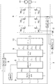
図1は、ブラシレスDCモータのセンサレス制御装置の構成を概略的に示している。 FIG. 1 schematically shows the configuration of a sensorless control device for a brushless DC motor.
このブラシレスDCモータのセンサレス制御装置は、自動車に搭載されて油の吸入および吐出を行うポンプ(11)を駆動するブラシレスDCモータ(1)を、自動車に搭載されたバッテリよりなる直流電源(2)を用いて、片側PWM方式で駆動するものであり、3相の相電圧に基づいてディジタル方式で各相の回転位置推定信号を生成する回転位置推定信号生成手段である回転位置推定信号生成装置(3)と、各相の回転位置推定信号に基づいてPWM方式で直流電源(2)から3相への通電を制御する通電制御手段である通電制御装置(4)とから構成されている。 This sensorless control device for a brushless DC motor includes a brushless DC motor (1) that drives a pump (11) that is mounted on an automobile and performs suction and discharge of oil, and a direct current power source (2) that includes a battery mounted on the automobile. Rotational position estimation signal generating device which is a rotational position estimation signal generating means for generating a rotational position estimation signal for each phase in a digital manner based on a three-phase phase voltage. 3) and an energization control device (4) which is an energization control means for controlling energization from the DC power supply (2) to the three phases by the PWM method based on the rotational position estimation signal of each phase.
回転位置推定信号生成装置(3)は、モータ(1)のU相、V相、W相の3相の相電圧Vu、Vv、Vwに基づいて、各相の回転位置推定信号Hu、Hv、Hwを生成する。3相の相電圧Vu、Vv、Vwは、Vで総称する。3相の回転位置推定信号Hu、Hv、Hwは、Hで総称する。 The rotational position estimation signal generation device (3) is based on the three phase voltages Vu, Vv, and Vw of the U phase, V phase, and W phase of the motor (1), and the rotational position estimation signals Hu, Hv, Hw is generated. The three phase voltages Vu, Vv, and Vw are collectively referred to as V. The three-phase rotational position estimation signals Hu, Hv, and Hw are collectively referred to as H.
通電制御装置(4)は、通電信号生成手段(5)と、スイッチング回路(6)と、電流検出器(7)と、電流制御部(8)と、PWM駆動手段(9)と、ゲートドライブ回路(10)とから構成されている。 The energization control device (4) includes an energization signal generation means (5), a switching circuit (6), a current detector (7), a current control section (8), a PWM drive means (9), and a gate drive. Circuit (10).
通電信号生成手段(5)は、回転位置推定信号生成手段(3)により生成される回転位置推定信号Hに基づいて、各素子の通電をそれぞれ制御するための通電信号Cu+、Cu−、Cv+、Cv−、Cw+、Cw−を生成するものである。通電信号は、Cで総称する。通電信号生成手段(5)は、MPU(Micro Processing Unit)により構成されてもよいし、専用のディジタル回路により構成されてもよい。 The energization signal generation means (5) is based on the rotational position estimation signal H generated by the rotational position estimation signal generation means (3), and the energization signals Cu +, Cu-, Cv +, Cv−, Cw +, and Cw− are generated. The energization signal is generally referred to as C. The energization signal generating means (5) may be constituted by an MPU (Micro Processing Unit) or a dedicated digital circuit.
スイッチング回路(6)は、電源(2)からモータ(1)のU相へ通電を制御する上アームスイッチング素子(16u+)および下アームスイッチング素子(16u-)、V相へ通電を制御する上アームスイッチング素子(16v+)および下アームスイッチング素子(16v-)、W相への通電を制御する上アームスイッチング素子(16w+)および下アームスイッチング素子(16w-)を備えている。スイッチング素子は、符号(16)で総称する。 The switching circuit (6) consists of an upper arm switching element (16u +) and a lower arm switching element (16u-) that control energization from the power source (2) to the U phase of the motor (1), and an upper arm that controls energization to the V phase. A switching element (16v +) and a lower arm switching element (16v−), an upper arm switching element (16w +) and a lower arm switching element (16w−) for controlling energization to the W phase are provided. The switching elements are collectively referred to by reference numeral (16).
電流検出器(7)は、電流測定回路をスイッチング回路(6)に接続してモータ電流を検出するものである。モータ(1)のU相、V相、W相のステータ巻線に流れる合計電流値が電流検出器(7)により検出されている。 The current detector (7) detects a motor current by connecting a current measurement circuit to the switching circuit (6). The total current value flowing in the U-phase, V-phase, and W-phase stator windings of the motor (1) is detected by the current detector (7).
直流電源(2)からスイッチング回路(6)を介してモータ(1)のU相、V相、W相のステータ巻線に流れる電源電流は、電源電流センサ(12)によって検出されている。 A power source current flowing from the DC power source (2) to the U-phase, V-phase, and W-phase stator windings of the motor (1) via the switching circuit (6) is detected by a power source current sensor (12).
電流制御部(8)は、電流検出器(7)から検出されたモータ(1)の電流検出値Aと電流指令値Aaとを比較し、両者の大小関係に基づき、モータ(1)をPWM駆動するための電流制御信号Apwmを作成し、PWM駆動手段(9)へ送るものである。電流制御部(8)は、電流指令値Aaが最大値のときに、モータ(1)のU相、V相、W相のステータ巻線にどれだけの電流を流すかを決定し、流れる電流の最大値を所定値以下に規制する。 The current control unit (8) compares the current detection value A of the motor (1) detected from the current detector (7) with the current command value Aa, and based on the magnitude relationship between the two, the motor (1) is PWMed. A current control signal Apwm for driving is created and sent to the PWM drive means (9). The current control unit (8) determines how much current flows through the U-phase, V-phase, and W-phase stator windings of the motor (1) when the current command value Aa is the maximum value. Is restricted to a predetermined value or less.
PWM駆動手段(9)は、与えられた通電信号Cおよび電流制御信号Apwmに基づいて、各スイッチング素子(16)に対するスイッチング素子制御信号Du+、Du−、Dv+、Dv−、Dw+、Dw−を作成し、ゲートドライブ回路(10)へ出力するものである。スイッチング素子制御信号はDで総称する。 The PWM drive means (9) creates switching element control signals Du +, Du−, Dv +, Dv−, Dw +, Dw− for each switching element (16) based on the supplied energization signal C and current control signal Apwm. And output to the gate drive circuit (10). The switching element control signals are collectively referred to as D.
ゲートドライブ回路(10)は、与えられたスイッチング素子制御信号Dに基づいて、各スイッチング素子(16)をオン/オフ駆動し、モータ(1)のステータ巻線に回転磁界を発生させるものである。 The gate drive circuit (10) drives each switching element (16) on / off based on a given switching element control signal D and generates a rotating magnetic field in the stator winding of the motor (1). .
図1において、起動時には、強制転流モードとされ、起動指令が通電信号生成手段(5)に与えられる。通電信号生成手段(5)は、起動指令を受けた際にメモリ内に記憶した通電パターンをPWM駆動手段(9)へ与える。これは、モータ(1)のロータ位置に関係なく行われる。電流については、電流制御部(8)からの電流制御信号Apwmによるのではなく、PWM駆動手段(9)のメモリに記憶された値に応じて、直流電源(2)から所要の電流が与えられる。この電流値は、モータの定格電流値よりも大きい値とされる。PWM駆動手段(9)は、通電信号生成手段(5)からの通電信号Cに基づいて、各スイッチング素子(16)に対するスイッチング素子制御信号Dをゲートドライブ回路(10)に出力し、これにより、各スイッチング素子(16)がオン/オフ駆動され、モータ(1)のステータ巻線に強制転流のための回転磁界が発生する。 In FIG. 1, at the time of start-up, the forced commutation mode is set and a start command is given to the energization signal generating means (5). The energization signal generating means (5) gives the energization pattern stored in the memory to the PWM drive means (9) when receiving the start command. This is done regardless of the rotor position of the motor (1). Regarding the current, a required current is given from the DC power source (2) according to the value stored in the memory of the PWM drive means (9), not by the current control signal Apwm from the current control unit (8). . This current value is larger than the rated current value of the motor. The PWM drive means (9) outputs a switching element control signal D for each switching element (16) to the gate drive circuit (10) based on the energization signal C from the energization signal generation means (5). Each switching element (16) is driven on / off, and a rotating magnetic field for forced commutation is generated in the stator winding of the motor (1).
強制転流を行うことで、モータ(1)のU相、V相、W相の3相の相電圧Vu、Vv、Vwが大きくなり、これに基づいて、回転位置推定信号生成手段(3)では、各相の回転位置推定信号H(Hu、Hv、Hw)が生成可能(すなわち、ロータ位置の検出が可能)となる。これにより、通電信号生成手段(5)は、回転位置推定信号生成手段(3)により生成される回転位置推定信号Hに基づいて、通電信号Cを生成する。PWM駆動手段(9)は、この通電信号Cおよび電流制御部(8)からの電流制御信号Apwmに基づいて、各スイッチング素子(16)に対するスイッチング素子制御信号Dを作成し、ゲートドライブ回路(10)に与える。こうして、強制転流モードからセンサレス制御モードに移行する。 By performing the forced commutation, the phase voltages Vu, Vv, Vw of the U phase, V phase, and W phase of the motor (1) increase, and based on this, the rotational position estimation signal generating means (3) Then, the rotational position estimation signal H (Hu, Hv, Hw) for each phase can be generated (that is, the rotor position can be detected). Thus, the energization signal generating means (5) generates the energization signal C based on the rotational position estimation signal H generated by the rotational position estimation signal generation means (3). Based on the energization signal C and the current control signal Apwm from the current control unit (8), the PWM drive means (9) creates a switching element control signal D for each switching element (16) and generates a gate drive circuit (10 ). Thus, the forced commutation mode shifts to the sensorless control mode.
電流制御部(8)では、センサレス制御モードへの移行直後の所定時間、電源電流最大値を定格電流値よりも大きくして移行初期センサレス制御を行い(第1のセンサレス制御モード)、この後、電源電流最大値を定格電流値に等しくした定常センサレス制御(第2のセンサレス制御モード)に移行する。 In the current control unit (8), for a predetermined time immediately after the transition to the sensorless control mode, the power supply current maximum value is made larger than the rated current value to perform the transition initial sensorless control (first sensorless control mode). A transition is made to steady sensorless control (second sensorless control mode) in which the power supply current maximum value is made equal to the rated current value.
第1のセンサレス制御モードでは、電流指令値Aaは、100%を最大値として、この100%最大値に保持され、電流制御部(8)における演算により、第1のセンサレス制御モード用の電源電流最大値が設定される。第2のセンサレス制御モードに移行する際、電流制御部(8)は、電源電流最大値を定格電流値に切り換える。 In the first sensorless control mode, the current command value Aa is held at the maximum value of 100% with the maximum value being 100%, and the power supply current for the first sensorless control mode is calculated by the calculation in the current control unit (8). The maximum value is set. When shifting to the second sensorless control mode, the current control unit (8) switches the power supply current maximum value to the rated current value.
図2は、強制転流モードからセンサレス制御モードに移行する際のフローチャートを示している。 FIG. 2 shows a flowchart when shifting from the forced commutation mode to the sensorless control mode.
同図において、起動指令(S1)に基づいて、強制転流モードが実行される(S2)。強制転流モード(S2)が終了すると、第1のセンサレス制御モードに移行する(S3)。この移行直後の第1のセンサレス制御モード(S3)は、電源電流の最大値をモータの定格電流値I0よりも大きい値I1に設定して行われる。これにより、センサレス制御モードへの移行直後では、定格電流値I0より大きい電流をモータに流すことが可能になり、大きなトルクが得られる。第1のセンサレス制御モード(S3)は、所定時間(T1sec間)に限定して行われ、所定時間経過後は、第2のセンサレス制御モードとされる(S4)。第2のセンサレス制御モード(S4)は、定常のセンサレス制御モードであり、電源電流の最大値がモータの定格電流値I0に等しくされる。第1のセンサレス制御モード(S3)が行われる時間T1、すなわち、電源電流最大値を定格電流値よりも大きくしたセンサレス制御が行われる時間T1は、短い所定時間(例えば1秒未満)に限定され、これにより、モータの負担が抑えられて、安全性が確保される。 In the figure, the forced commutation mode is executed based on the start command (S1) (S2). When the forced commutation mode (S2) ends, the process shifts to the first sensorless control mode (S3). The first sensorless control mode (S3) immediately after the transition is performed by setting the maximum value of the power supply current to a value I1 larger than the rated current value I0 of the motor. As a result, immediately after shifting to the sensorless control mode, it becomes possible to flow a current larger than the rated current value I0 to the motor, and a large torque can be obtained. The first sensorless control mode (S3) is performed only for a predetermined time (during T1 sec), and after the predetermined time has elapsed, the second sensorless control mode is set (S4). The second sensorless control mode (S4) is a steady sensorless control mode in which the maximum value of the power supply current is made equal to the rated current value I0 of the motor. The time T1 during which the first sensorless control mode (S3) is performed, that is, the time T1 during which sensorless control is performed with the maximum power supply current value larger than the rated current value is limited to a short predetermined time (for example, less than 1 second). As a result, the burden on the motor is reduced and safety is ensured.
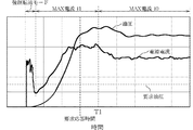
図3は、ポンプ(11)において、時間とともに油圧および電源電流がどのように変化するかを求めたものである。 FIG. 3 shows how the hydraulic pressure and the power supply current change with time in the pump (11).
同図において、強制転流モードが終了してセンサレス制御モードに移行すると、モータの回転数が増加することで、油圧が増加していく。電源電流センサ(12)によって検出される電源電流値も回転数とともに増加していく。センサレス制御モードに移行直後では、電源電流の最大値が定格電流値I0よりも高い値I1に設定されており、モータのトルクが大きいものとなり、短い時間で要求油圧に達することが可能となる。 In the figure, when the forced commutation mode ends and the mode shifts to the sensorless control mode, the hydraulic pressure increases as the number of rotations of the motor increases. The power supply current value detected by the power supply current sensor (12) also increases with the rotational speed. Immediately after shifting to the sensorless control mode, the maximum value of the power supply current is set to a value I1 higher than the rated current value I0, the motor torque becomes large, and the required oil pressure can be reached in a short time.
上記において、モータの定格電流値I0は、油温が低いなどの理由によって油圧負荷が高くなっている場合でも、所要の応答時間内に要求油圧に到達するように設定される。センサレス制御モードに移行直後の電源電流最大値I1およびこの電源電流最大値I1で制御する時間T1は、要求油圧およびこれに到達する要求応答時間に応じて設定される。例えば、センサレス制御モードに移行直後の電源電流最大値I1は、定格電流値I0×1.2〜2.0程度とされ、移行直後の電源電流最大値I1で制御する時間は、例えば、0.2secから1.0sec未満程度とされる。また、強制転流モードの電流値I2は、定格電流値I0と移行直後の電源電流最大値I1との間の値に設定される。定格電流値I0、移行直後の電源電流最大値I1およびこの電源電流最大値I1で制御する時間T1の設定値をモータごとに適宜設定することで、モータが変わった場合でも容易に対応することができる。 In the above, the rated current value I0 of the motor is set so as to reach the required hydraulic pressure within the required response time even when the hydraulic load is high due to a low oil temperature or the like. The power supply current maximum value I1 immediately after the transition to the sensorless control mode and the time T1 controlled by the power supply current maximum value I1 are set according to the required oil pressure and the required response time to reach this. For example, the power supply current maximum value I1 immediately after the transition to the sensorless control mode is set to the rated current value I0 × 1.2 to 2.0, and the control time with the power supply current maximum value I1 immediately after the transition is, for example, 0. 2 sec to less than 1.0 sec. The current value I2 in the forced commutation mode is set to a value between the rated current value I0 and the power supply current maximum value I1 immediately after the transition. By appropriately setting the set value of the rated current value I0, the power supply current maximum value I1 immediately after the transition, and the time T1 controlled by the power supply current maximum value I1 for each motor, it is possible to easily cope with a change in the motor. it can.
上記実施形態では、車載用電動油圧ポンプ(11)の駆動用として使用されるブラシレスDCモータ(1)について説明したが、この発明は、120度通電矩形波駆動を採用するすべてのブラシレスDCモータのセンサレス駆動装置にも適用することができる。 In the above embodiment, the brushless DC motor (1) used for driving the on-vehicle electric hydraulic pump (11) has been described. However, the present invention is applicable to all brushless DC motors that employ a 120-degree conduction rectangular wave drive. The present invention can also be applied to a sensorless driving device.
なお、図1に示すブロック図において、電流制御部(8)に追加して、または、これに代えて、速度制御部を設けるようにしてもよい。速度制御部は、モータ(1)の回転子の回転速度検出値Sと外部から与えられた回転方向を含む回転速度設定値Saとを比較し、両者の大小関係に基づいて、モータ(1)をPWM駆動するための速度制御信号Spwmを作成し、PWM駆動手段(9)へ出力するものとされる。 In the block diagram shown in FIG. 1, a speed control unit may be provided in addition to or instead of the current control unit (8). The speed control unit compares the rotation speed detection value S of the rotor of the motor (1) with the rotation speed setting value Sa including the rotation direction given from the outside, and based on the magnitude relationship between the two, the motor (1) A speed control signal Spwm for PWM driving is generated and output to the PWM driving means (9).
(1) :ブラシレスDCモータ、(11):ポンプ (1): Brushless DC motor, (11): Pump
Claims (2)
通電制御装置は、
電流検出器と、
起動指令信号または回転位置推定信号に基づいてスイッチング回路の各素子の通電を制御するための通電信号を生成する通電信号生成手段と、
モータのステータに流す電流を決定し、さらに、各モードで流す電流の最大値である電源電流最大値を所定値以下に規制する電流制御部とを備え、
前記電流制御部は、各モードでのモータのステータに流す電流を各モードの電源電流最大値となるように設定し、電流検出器からの電流信号に基づいて、強制転流モードからセンサレス制御モードに移行直後の所定時間、電源電流最大値を強制転流モードでの電源電流最大値より大きく、かつ、モータ定格電流値より大きくするとともに、前記移行から所定時間経過後、電源電流最大値をモータ定格電流値に等しくすることを特徴とするブラシレスDCモータのセンサレス制御装置。
In a sensorless control device for a brushless DC motor provided with an energization control device that shifts to a sensorless control mode when the brushless DC motor is rotated as a forced commutation mode at startup and the rotor position can be detected,
The energization control device
A current detector;
Energization signal generating means for generating an energization signal for controlling energization of each element of the switching circuit based on the start command signal or the rotational position estimation signal;
A current control unit that determines a current that flows to the stator of the motor, and further regulates a power supply current maximum value that is a maximum value of a current that flows in each mode to a predetermined value or less;
The current control unit is configured to set the current flowing through the stator of the motor in each mode to the maximum power supply current value in each mode, and from the forced commutation mode to the sensorless control mode based on the current signal from the current detector. The power supply current maximum value is set to be larger than the power supply current maximum value in the forced commutation mode and the motor rated current value for a predetermined time immediately after the transition to A sensorless control device for a brushless DC motor, characterized by being equal to a rated current value .
Priority Applications (4)
| Application Number | Priority Date | Filing Date | Title |
|---|---|---|---|
| JP2011143790A JP5853438B2 (en) | 2011-06-29 | 2011-06-29 | Sensorless control device for brushless DC motor |
| US13/490,933 US8729840B2 (en) | 2011-06-29 | 2012-06-07 | Sensorless control unit for brushless DC motor |
| CN201210191650.XA CN102857163B (en) | 2011-06-29 | 2012-06-11 | The sensor-less control device of brushless DC motor |
| EP12171724.3A EP2541756B1 (en) | 2011-06-29 | 2012-06-13 | Sensorless control unit for brushless DC motor |
Applications Claiming Priority (1)
| Application Number | Priority Date | Filing Date | Title |
|---|---|---|---|
| JP2011143790A JP5853438B2 (en) | 2011-06-29 | 2011-06-29 | Sensorless control device for brushless DC motor |
Publications (3)
| Publication Number | Publication Date |
|---|---|
| JP2013013215A JP2013013215A (en) | 2013-01-17 |
| JP2013013215A5 JP2013013215A5 (en) | 2014-07-17 |
| JP5853438B2 true JP5853438B2 (en) | 2016-02-09 |
Family
ID=46354011
Family Applications (1)
| Application Number | Title | Priority Date | Filing Date |
|---|---|---|---|
| JP2011143790A Expired - Fee Related JP5853438B2 (en) | 2011-06-29 | 2011-06-29 | Sensorless control device for brushless DC motor |
Country Status (4)
| Country | Link |
|---|---|
| US (1) | US8729840B2 (en) |
| EP (1) | EP2541756B1 (en) |
| JP (1) | JP5853438B2 (en) |
| CN (1) | CN102857163B (en) |
Families Citing this family (5)
| Publication number | Priority date | Publication date | Assignee | Title |
|---|---|---|---|---|
| JP5853438B2 (en) * | 2011-06-29 | 2016-02-09 | 株式会社ジェイテクト | Sensorless control device for brushless DC motor |
| US9666224B1 (en) | 2016-02-23 | 2017-05-30 | Western Digital Technologies, Inc. | Data storage device adaptively estimating spindle motor current |
| US10613518B2 (en) * | 2018-03-26 | 2020-04-07 | Mitsubishi Electric Corporation | Servo control device |
| FR3093139B1 (en) * | 2019-02-21 | 2021-01-22 | Renault Sas | PROCESS FOR CHECKING THE START OF AN OIL PUMP |
| CN113437910A (en) * | 2020-03-23 | 2021-09-24 | 致新科技股份有限公司 | Motor controller |
Family Cites Families (23)
| Publication number | Priority date | Publication date | Assignee | Title |
|---|---|---|---|---|
| JP3298902B2 (en) | 1991-06-07 | 2002-07-08 | 日本電産株式会社 | DC motor operation method and operation circuit |
| US5557180A (en) * | 1993-06-30 | 1996-09-17 | Sgs-Thomson Microelectronics, Inc. | Circuit and method for operating a 3-phase motor with a uni-coil phase commutation scheme |
| MY119900A (en) | 1995-03-14 | 2005-08-30 | Panasonic Corp | Refrigerating apparatus, and refrigerator control and brushless motor starter used in same |
| JP3726683B2 (en) * | 1998-07-16 | 2005-12-14 | セイコーエプソン株式会社 | Method and apparatus for controlling position sensorless motor |
| JP2000253691A (en) * | 1999-03-02 | 2000-09-14 | Matsushita Electric Ind Co Ltd | Apparatus and method for controlling brushless motor |
| JP4253906B2 (en) * | 1999-03-31 | 2009-04-15 | パナソニック電工株式会社 | Brushless motor control device, control method therefor, and self-priming pump |
| JP4465770B2 (en) * | 2000-01-17 | 2010-05-19 | パナソニック電工株式会社 | Brushless motor control device and self-priming pump using the same |
| JP3690250B2 (en) * | 2000-07-19 | 2005-08-31 | セイコーエプソン株式会社 | Sensorless motor drive device |
| JP3940267B2 (en) * | 2001-02-21 | 2007-07-04 | 株式会社ジェイテクト | Synchronous motor start control device and electric pump for controlling working fluid of automobile drive system using the device |
| JP3690296B2 (en) * | 2001-03-26 | 2005-08-31 | セイコーエプソン株式会社 | Sensorless motor drive device |
| JP2003182391A (en) * | 2001-12-25 | 2003-07-03 | Koyo Seiko Co Ltd | Driving force transmission for vehicle |
| US6989646B2 (en) * | 2002-04-29 | 2006-01-24 | Stuart Pollard Jackson | Multi-axis air/electrical control system |
| JP4218317B2 (en) | 2002-11-15 | 2009-02-04 | アイシン精機株式会社 | Electric fluid pump device |
| JP2005278320A (en) | 2004-03-25 | 2005-10-06 | Koyo Seiko Co Ltd | Starting method of brushless motor, control device of brushless motor and electric pump |
| KR101041076B1 (en) * | 2004-12-17 | 2011-06-13 | 삼성전자주식회사 | Method for control starting of brushless DC motor |
| JP2007174748A (en) * | 2005-12-19 | 2007-07-05 | Jtekt Corp | Motor driving circuit |
| JP2008086117A (en) * | 2006-09-27 | 2008-04-10 | Aisin Seiki Co Ltd | Electric fluid pump |
| JP4277919B2 (en) * | 2007-05-22 | 2009-06-10 | 株式会社デンソー | Motor drive device and motor drive control method |
| JP5396828B2 (en) * | 2008-11-20 | 2014-01-22 | 株式会社ジェイテクト | Brushless motor stability controller |
| JP2010233301A (en) | 2009-03-26 | 2010-10-14 | Hitachi Car Eng Co Ltd | Sensorless brushless motor control device and electric fluid pump using the same |
| JP5670258B2 (en) * | 2011-05-31 | 2015-02-18 | 日立オートモティブシステムズ株式会社 | Brushless motor drive device |
| JP5998434B2 (en) * | 2011-06-23 | 2016-09-28 | 株式会社ジェイテクト | Sensorless control device for brushless DC motor |
| JP5853438B2 (en) * | 2011-06-29 | 2016-02-09 | 株式会社ジェイテクト | Sensorless control device for brushless DC motor |
-
2011
- 2011-06-29 JP JP2011143790A patent/JP5853438B2/en not_active Expired - Fee Related
-
2012
- 2012-06-07 US US13/490,933 patent/US8729840B2/en not_active Expired - Fee Related
- 2012-06-11 CN CN201210191650.XA patent/CN102857163B/en not_active Expired - Fee Related
- 2012-06-13 EP EP12171724.3A patent/EP2541756B1/en not_active Not-in-force
Also Published As
| Publication number | Publication date |
|---|---|
| US8729840B2 (en) | 2014-05-20 |
| US20130002177A1 (en) | 2013-01-03 |
| CN102857163A (en) | 2013-01-02 |
| CN102857163B (en) | 2017-06-20 |
| EP2541756A1 (en) | 2013-01-02 |
| EP2541756B1 (en) | 2017-01-11 |
| JP2013013215A (en) | 2013-01-17 |
Similar Documents
| Publication | Publication Date | Title |
|---|---|---|
| JP5998434B2 (en) | Sensorless control device for brushless DC motor | |
| JP2008141828A (en) | Motor driving device and motor driving method | |
| JP4735681B2 (en) | MOTOR CONTROL CIRCUIT, VEHICLE FAN DRIVE DEVICE, AND MOTOR CONTROL METHOD | |
| JP4513914B2 (en) | MOTOR CONTROL CIRCUIT, VEHICLE FAN DRIVE DEVICE, AND MOTOR CONTROL METHOD | |
| JP5853438B2 (en) | Sensorless control device for brushless DC motor | |
| US20150211533A1 (en) | Electric compressor | |
| JP6535317B2 (en) | Motor drive control device and motor drive control method | |
| JP2007074834A (en) | Starter for sensorless motors | |
| JP5396828B2 (en) | Brushless motor stability controller | |
| CN107482965B (en) | Control device for synchronous motor | |
| JP2005312145A (en) | Driver of brushless motor | |
| JP4085818B2 (en) | DC motor driving method and DC motor driving apparatus | |
| JP2005278320A (en) | Starting method of brushless motor, control device of brushless motor and electric pump | |
| JP5998656B2 (en) | Electric motor control device | |
| JP2013219841A (en) | Sensorless controller of brushless dc motor | |
| JP5298778B2 (en) | Brushless motor drive device | |
| JP2013236431A (en) | Control method and control apparatus for brushless motor | |
| JP2012239301A (en) | Motor controller | |
| JP5724353B2 (en) | Brushless motor control device for electric pump | |
| JP2007189807A (en) | Controller of motor for vehicle | |
| JP2007174747A (en) | Sensorless control method for brushless motor, and sensorless controller for brushless motor | |
| JP2007236153A (en) | Sensorless drive method and device for brushless motor | |
| JP5998556B2 (en) | Sensorless control device for brushless DC motor | |
| JP2012239340A (en) | Motor drive device | |
| JP2006121815A (en) | Drive device of dc brushless motor |
Legal Events
| Date | Code | Title | Description |
|---|---|---|---|
| A621 | Written request for application examination |
Free format text: JAPANESE INTERMEDIATE CODE: A621 Effective date: 20140519 |
|
| A521 | Written amendment |
Free format text: JAPANESE INTERMEDIATE CODE: A523 Effective date: 20140604 |
|
| A977 | Report on retrieval |
Free format text: JAPANESE INTERMEDIATE CODE: A971007 Effective date: 20150325 |
|
| A131 | Notification of reasons for refusal |
Free format text: JAPANESE INTERMEDIATE CODE: A131 Effective date: 20150331 |
|
| A521 | Written amendment |
Free format text: JAPANESE INTERMEDIATE CODE: A523 Effective date: 20150508 |
|
| TRDD | Decision of grant or rejection written | ||
| A01 | Written decision to grant a patent or to grant a registration (utility model) |
Free format text: JAPANESE INTERMEDIATE CODE: A01 Effective date: 20151110 |
|
| A61 | First payment of annual fees (during grant procedure) |
Free format text: JAPANESE INTERMEDIATE CODE: A61 Effective date: 20151123 |
|
| R150 | Certificate of patent or registration of utility model |
Ref document number: 5853438 Country of ref document: JP Free format text: JAPANESE INTERMEDIATE CODE: R150 |
|
| LAPS | Cancellation because of no payment of annual fees |