EP3386051A1 - Electronic protection device for detecting arcing fault - Google Patents
Electronic protection device for detecting arcing fault Download PDFInfo
- Publication number
- EP3386051A1 EP3386051A1 EP17164776.1A EP17164776A EP3386051A1 EP 3386051 A1 EP3386051 A1 EP 3386051A1 EP 17164776 A EP17164776 A EP 17164776A EP 3386051 A1 EP3386051 A1 EP 3386051A1
- Authority
- EP
- European Patent Office
- Prior art keywords
- detection signal
- signal
- logic
- protection device
- indicative
- Prior art date
- Legal status (The legal status is an assumption and is not a legal conclusion. Google has not performed a legal analysis and makes no representation as to the accuracy of the status listed.)
- Granted
Links
- 239000004020 conductor Substances 0.000 claims abstract description 27
- 238000001514 detection method Methods 0.000 claims description 185
- 230000007704 transition Effects 0.000 claims description 41
- 230000006399 behavior Effects 0.000 claims description 37
- 238000000034 method Methods 0.000 claims description 31
- 230000008569 process Effects 0.000 claims description 15
- 230000007246 mechanism Effects 0.000 claims description 14
- 230000004044 response Effects 0.000 claims description 4
- 238000006243 chemical reaction Methods 0.000 claims description 3
- 238000004804 winding Methods 0.000 description 10
- 101100395484 Arabidopsis thaliana HPD gene Proteins 0.000 description 9
- 101100463166 Oryza sativa subsp. japonica PDS gene Proteins 0.000 description 9
- 101150061817 PDS1 gene Proteins 0.000 description 9
- 238000005070 sampling Methods 0.000 description 8
- 101000988374 Arabidopsis thaliana Sister chromatid cohesion protein PDS5 homolog A Proteins 0.000 description 7
- 102100039166 Sister chromatid cohesion protein PDS5 homolog A Human genes 0.000 description 7
- 230000002093 peripheral effect Effects 0.000 description 7
- 101100532680 Saccharomyces cerevisiae (strain ATCC 204508 / S288c) MCD1 gene Proteins 0.000 description 6
- 102100028043 Fibroblast growth factor 3 Human genes 0.000 description 4
- 102100024061 Integrator complex subunit 1 Human genes 0.000 description 4
- 101710092857 Integrator complex subunit 1 Proteins 0.000 description 4
- 108050002021 Integrator complex subunit 2 Proteins 0.000 description 4
- 238000004458 analytical method Methods 0.000 description 3
- 230000007935 neutral effect Effects 0.000 description 3
- 238000011144 upstream manufacturing Methods 0.000 description 3
- 101000854862 Homo sapiens Vacuolar protein sorting-associated protein 35 Proteins 0.000 description 2
- 102100020822 Vacuolar protein sorting-associated protein 35 Human genes 0.000 description 2
- 238000001914 filtration Methods 0.000 description 2
- 239000000463 material Substances 0.000 description 2
- 230000010355 oscillation Effects 0.000 description 2
- 230000035699 permeability Effects 0.000 description 2
- 230000001902 propagating effect Effects 0.000 description 2
- XEEYBQQBJWHFJM-UHFFFAOYSA-N Iron Chemical compound [Fe] XEEYBQQBJWHFJM-UHFFFAOYSA-N 0.000 description 1
- 229910000831 Steel Inorganic materials 0.000 description 1
- 230000032683 aging Effects 0.000 description 1
- 230000003321 amplification Effects 0.000 description 1
- 230000015572 biosynthetic process Effects 0.000 description 1
- 239000003990 capacitor Substances 0.000 description 1
- 230000002860 competitive effect Effects 0.000 description 1
- 230000001419 dependent effect Effects 0.000 description 1
- 238000010586 diagram Methods 0.000 description 1
- 239000012777 electrically insulating material Substances 0.000 description 1
- 230000006870 function Effects 0.000 description 1
- 238000009434 installation Methods 0.000 description 1
- 230000005923 long-lasting effect Effects 0.000 description 1
- 238000004519 manufacturing process Methods 0.000 description 1
- 238000003199 nucleic acid amplification method Methods 0.000 description 1
- 230000035945 sensitivity Effects 0.000 description 1
- 230000003595 spectral effect Effects 0.000 description 1
- 239000010959 steel Substances 0.000 description 1
- 229910000859 α-Fe Inorganic materials 0.000 description 1
Images


Classifications
-
- H—ELECTRICITY
- H02—GENERATION; CONVERSION OR DISTRIBUTION OF ELECTRIC POWER
- H02H—EMERGENCY PROTECTIVE CIRCUIT ARRANGEMENTS
- H02H3/00—Emergency protective circuit arrangements for automatic disconnection directly responsive to an undesired change from normal electric working condition with or without subsequent reconnection ; integrated protection
- H02H3/26—Emergency protective circuit arrangements for automatic disconnection directly responsive to an undesired change from normal electric working condition with or without subsequent reconnection ; integrated protection responsive to difference between voltages or between currents; responsive to phase angle between voltages or between currents
- H02H3/28—Emergency protective circuit arrangements for automatic disconnection directly responsive to an undesired change from normal electric working condition with or without subsequent reconnection ; integrated protection responsive to difference between voltages or between currents; responsive to phase angle between voltages or between currents involving comparison of the voltage or current values at two spaced portions of a single system, e.g. at opposite ends of one line, at input and output of apparatus
-
- H—ELECTRICITY
- H02—GENERATION; CONVERSION OR DISTRIBUTION OF ELECTRIC POWER
- H02H—EMERGENCY PROTECTIVE CIRCUIT ARRANGEMENTS
- H02H7/00—Emergency protective circuit arrangements specially adapted for specific types of electric machines or apparatus or for sectionalised protection of cable or line systems, and effecting automatic switching in the event of an undesired change from normal working conditions
- H02H7/26—Sectionalised protection of cable or line systems, e.g. for disconnecting a section on which a short-circuit, earth fault, or arc discharge has occured
- H02H7/261—Sectionalised protection of cable or line systems, e.g. for disconnecting a section on which a short-circuit, earth fault, or arc discharge has occured involving signal transmission between at least two stations
- H02H7/262—Sectionalised protection of cable or line systems, e.g. for disconnecting a section on which a short-circuit, earth fault, or arc discharge has occured involving signal transmission between at least two stations involving transmissions of switching or blocking orders
-
- H—ELECTRICITY
- H02—GENERATION; CONVERSION OR DISTRIBUTION OF ELECTRIC POWER
- H02H—EMERGENCY PROTECTIVE CIRCUIT ARRANGEMENTS
- H02H1/00—Details of emergency protective circuit arrangements
- H02H1/0092—Details of emergency protective circuit arrangements concerning the data processing means, e.g. expert systems, neural networks
-
- G—PHYSICS
- G01—MEASURING; TESTING
- G01R—MEASURING ELECTRIC VARIABLES; MEASURING MAGNETIC VARIABLES
- G01R31/00—Arrangements for testing electric properties; Arrangements for locating electric faults; Arrangements for electrical testing characterised by what is being tested not provided for elsewhere
- G01R31/12—Testing dielectric strength or breakdown voltage ; Testing or monitoring effectiveness or level of insulation, e.g. of a cable or of an apparatus, for example using partial discharge measurements; Electrostatic testing
- G01R31/1227—Testing dielectric strength or breakdown voltage ; Testing or monitoring effectiveness or level of insulation, e.g. of a cable or of an apparatus, for example using partial discharge measurements; Electrostatic testing of components, parts or materials
- G01R31/1263—Testing dielectric strength or breakdown voltage ; Testing or monitoring effectiveness or level of insulation, e.g. of a cable or of an apparatus, for example using partial discharge measurements; Electrostatic testing of components, parts or materials of solid or fluid materials, e.g. insulation films, bulk material; of semiconductors or LV electronic components or parts; of cable, line or wire insulation
- G01R31/1272—Testing dielectric strength or breakdown voltage ; Testing or monitoring effectiveness or level of insulation, e.g. of a cable or of an apparatus, for example using partial discharge measurements; Electrostatic testing of components, parts or materials of solid or fluid materials, e.g. insulation films, bulk material; of semiconductors or LV electronic components or parts; of cable, line or wire insulation of cable, line or wire insulation, e.g. using partial discharge measurements
-
- H—ELECTRICITY
- H02—GENERATION; CONVERSION OR DISTRIBUTION OF ELECTRIC POWER
- H02H—EMERGENCY PROTECTIVE CIRCUIT ARRANGEMENTS
- H02H1/00—Details of emergency protective circuit arrangements
- H02H1/0007—Details of emergency protective circuit arrangements concerning the detecting means
- H02H1/0015—Using arc detectors
-
- H—ELECTRICITY
- H02—GENERATION; CONVERSION OR DISTRIBUTION OF ELECTRIC POWER
- H02H—EMERGENCY PROTECTIVE CIRCUIT ARRANGEMENTS
- H02H3/00—Emergency protective circuit arrangements for automatic disconnection directly responsive to an undesired change from normal electric working condition with or without subsequent reconnection ; integrated protection
- H02H3/08—Emergency protective circuit arrangements for automatic disconnection directly responsive to an undesired change from normal electric working condition with or without subsequent reconnection ; integrated protection responsive to excess current
-
- H—ELECTRICITY
- H02—GENERATION; CONVERSION OR DISTRIBUTION OF ELECTRIC POWER
- H02H—EMERGENCY PROTECTIVE CIRCUIT ARRANGEMENTS
- H02H7/00—Emergency protective circuit arrangements specially adapted for specific types of electric machines or apparatus or for sectionalised protection of cable or line systems, and effecting automatic switching in the event of an undesired change from normal working conditions
- H02H7/26—Sectionalised protection of cable or line systems, e.g. for disconnecting a section on which a short-circuit, earth fault, or arc discharge has occured
- H02H7/261—Sectionalised protection of cable or line systems, e.g. for disconnecting a section on which a short-circuit, earth fault, or arc discharge has occured involving signal transmission between at least two stations
- H02H7/263—Sectionalised protection of cable or line systems, e.g. for disconnecting a section on which a short-circuit, earth fault, or arc discharge has occured involving signal transmission between at least two stations involving transmissions of measured values
-
- H—ELECTRICITY
- H03—ELECTRONIC CIRCUITRY
- H03K—PULSE TECHNIQUE
- H03K21/00—Details of pulse counters or frequency dividers
- H03K21/08—Output circuits
-
- H—ELECTRICITY
- H02—GENERATION; CONVERSION OR DISTRIBUTION OF ELECTRIC POWER
- H02H—EMERGENCY PROTECTIVE CIRCUIT ARRANGEMENTS
- H02H3/00—Emergency protective circuit arrangements for automatic disconnection directly responsive to an undesired change from normal electric working condition with or without subsequent reconnection ; integrated protection
- H02H3/08—Emergency protective circuit arrangements for automatic disconnection directly responsive to an undesired change from normal electric working condition with or without subsequent reconnection ; integrated protection responsive to excess current
- H02H3/10—Emergency protective circuit arrangements for automatic disconnection directly responsive to an undesired change from normal electric working condition with or without subsequent reconnection ; integrated protection responsive to excess current additionally responsive to some other abnormal electrical conditions
-
- H—ELECTRICITY
- H02—GENERATION; CONVERSION OR DISTRIBUTION OF ELECTRIC POWER
- H02H—EMERGENCY PROTECTIVE CIRCUIT ARRANGEMENTS
- H02H3/00—Emergency protective circuit arrangements for automatic disconnection directly responsive to an undesired change from normal electric working condition with or without subsequent reconnection ; integrated protection
- H02H3/16—Emergency protective circuit arrangements for automatic disconnection directly responsive to an undesired change from normal electric working condition with or without subsequent reconnection ; integrated protection responsive to fault current to earth, frame or mass
- H02H3/162—Emergency protective circuit arrangements for automatic disconnection directly responsive to an undesired change from normal electric working condition with or without subsequent reconnection ; integrated protection responsive to fault current to earth, frame or mass for ac systems
-
- H—ELECTRICITY
- H02—GENERATION; CONVERSION OR DISTRIBUTION OF ELECTRIC POWER
- H02H—EMERGENCY PROTECTIVE CIRCUIT ARRANGEMENTS
- H02H3/00—Emergency protective circuit arrangements for automatic disconnection directly responsive to an undesired change from normal electric working condition with or without subsequent reconnection ; integrated protection
- H02H3/20—Emergency protective circuit arrangements for automatic disconnection directly responsive to an undesired change from normal electric working condition with or without subsequent reconnection ; integrated protection responsive to excess voltage
Definitions
- the present invention relates to an electronic protection device for low voltage (LV) electric lines.
- an electronic protection device for a LV electric line generally consists in a circuit breaker equipped with an electronic control unit typically including at least a microcontroller.
- An electronic protection device is normally operatively associated with the conductors of an electric line to interrupt the line current flowing along this latter in case of fault conditions.
- Typical fault conditions include, for example, ground fault conditions, over-voltage conditions, over-current conditions, arc fault conditions and the like.
- arcing phenomena occur quite often in an electric line as they are mainly due to the formation of a ionized gas currents between two conductive elements of the electric line at different voltage potentials, e.g. two electric contacts, two conductors, a conductor and the ground, etc.
- the electronic protection device is required to promptly intervene to interrupt the electric line.
- Some electronic protection devices of the state of the art include electronic arrangements configured to analyze the amplitude of broadband noise propagating along the electric line and determine the presence of arc fault conditions on the base of this analysis.
- the present invention provides an electronic protection device according to the following claim 1 and the related dependent claims.
- the electronic protection device comprises:
- the control unit of the electronic protection device of the invention comprises:
- the first detection module comprises:
- the first processing stage comprises:
- the second detection module comprises:
- the processing stage comprises:
- said third detection module is adapted to provide a third detection signal formed by a sequence of count values separated by a constant time intervals, each count value being indicative of a number of level transitions of said logic signal occurring within a corresponding time interval.
- said third detection module may comprise:
- said third detection module may comprise:
- said third detection module is adapted to provide a third detection signal formed by a sequence of logic values separated by constant time intervals, each logic value being indicative of the presence of at least a level transition in said logic signal within a corresponding time interval.
- said third detection module may comprise:
- the determination module is adapted to execute a determination procedure comprising the following steps:
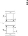
- the present invention relates to an electronic protection device 1, which, in operation, is associated to a low-voltage electric line 100.
- LV low voltage
- the electric line 100 comprises one or more phase conductors P and, preferably, a neutral conductor N.
- the electric line 100 comprises a single phase conductor P and a neutral conductor N.
- the electronic protection device 1 will be described with reference to its installation in an electric line having a single phase conductor P and a neutral conductor N for the sake of simplicity only, without intending to limit the scope of the invention.
- the electric line 100 may, in fact, have different arrangements for its own conductors, according to the needs.
- the electric line 100 is intended to electrically connect an electric power source SC and an electric load LD, which may be of any type.
- the electronic protection device 1 allows or interrupts a current flow IL between the electric power source SC and the electric load LD, more precisely between upstream portions 100A and downstream portions 100B of the electric line 100, which are electrically connected with the electric power source SC and the electric load LD, respectively.
- the electronic protection device 1 may be arranged according to different configurations.
- the electronic protection device 1 can take three different operative states, namely a closed state, a tripped state and an open state, during its operating life.
- the electronic protection device 1 can take two different operative states, namely a closed state and an open state, during its operating life.
- the electronic protection device 1 When it operates in a closed state, the electronic protection device 1 allows a current IL to flow along the electric line 100 between the upstream and downstream portions 100A, 100B of this latter.
- the electronic protection device 1 When it operates in a tripped state or open state, the electronic protection device 1 interrupts the current IL along the electric line 100, thereby electrically disconnecting the upstream and downstream portions 100A, 100B of this latter.
- the electronic protection device 1 comprises an outer casing (not shown), preferably made of electrically insulating material, which defines an internal volume to accommodate the components of said electronic protection device.
- the electronic protection device 1 comprises one or more pairs of electric contacts 10, including a mobile contact and a fixed contact.
- Each pair of electric contacts 10 is intended to be electrically connected to a corresponding conductor of the electric line 100 and, in operation, can be mutually coupled or separated.
- the protection device 1 When the electric contacts 10 are mutually coupled, the protection device 1 is in a closed state and an electric current IL can flow along the corresponding conductor of the electric line 100. When the electric contacts 10 are decoupled, the protection device 1 is in a tripped state or open state and an electric current IL is prevented from flowing along the corresponding conductor of the electric line 100.
- the electric contacts 10 and their electrical connection with the corresponding conductors of the electric line 100 may be realized in known manners that will not here described in more details for the sake of brevity.
- the pairs of electric contacts 10 of the electronic protection device are all operated in a coordinated manner in a coupled state or in a decoupled state for obvious purposes of electrical continuity and current balancing.
- the electric protection device 1 comprises an operating mechanism 11 operatively coupled with the electric contacts 10 (in particular with the mobile contacts thereof) and mechanically interacting with these latter.
- the electric protection device 1 comprises a tripping unit 12 adapted to mechanically actuate the operating mechanism 11.
- the tripping unit 12 actuates the operating mechanism 11 to decouple the electric contacts 10, thereby carrying out a tripping manoeuver of the electronic protection device.
- the tripping unit 12 comprises an electromagnetic actuator.
- the tripping unit 12 is fed by the electric line 100 through a power supply unit (not shown) of the electronic protection device.
- the electric protection device 1 conveniently comprises other mechanical components, e.g. a handle 13 operatively coupled with the operating mechanism 11 and mechanically interacting with this latter.
- the handle 13 is movable (preferably around a suitable rotation axis) between two or three operating positions (depending on the configuration of the electronic protection device).
- the handle 13 may be actuated by the operating mechanism 11, by a user or by external equipment during a tripping or opening maneuver of the electronic protection device.
- the handle 13 may actuate the operating mechanism 11 in order to couple or decouple or maintain decoupled (depending on the configuration of the electronic protection device) the electric contacts 10 during an opening manoeuver or a closing maneuver of the electronic protection device.
- the operating mechanism 11, the tripping unit 12 and the handle 13 may be realized and operatively coupled in known manners that will not here described in more details for the sake of brevity.
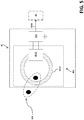
- the electronic protection device 1 comprises a control unit 2 for controlling the operation of said electronic protection device.
- the control unit 2 comprises a controller 20, e.g. a microcontroller.
- control unit 2 is fed by the electric line 100 through a power supply unit (not shown) of the electronic protection device.
- the controller 20 conveniently include data processing resources of digital type, e.g. a CPU capable of executing stored software instructions, peripheral modules and I/O ports to carry out its functionalities, according to the needs.
- data processing resources of digital type e.g. a CPU capable of executing stored software instructions, peripheral modules and I/O ports to carry out its functionalities, according to the needs.
- control unit 2 An important function of the control unit 2 consists in providing a trip signal TS to activate the tripping unit 12 when fault conditions, which require a tripping manoeuvre of the electronic protection device, are present in the electric line 100.
- Fault conditions may include ground fault conditions, arc fault conditions, over-current conditions, over-voltage conditions, internal fault conditions in the electronic protection device, and so on.
- the control unit 2 may comprise suitable arrangements (not shown) to detect and determine the presence of ground fault conditions, over-current conditions, over-voltage conditions in the electric line 100 and/or of internal fault conditions in the electronic protection device. Such arrangements may be of known type and will not here further described for the sake of brevity.
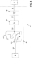
- control unit 2 is characterised by an innovative arrangement (references 3, 4, 5, 6, 7 of the cited figures) to detect and determine the presence of arc fault conditions in the electric line 100.
- control unit 2 comprises:
- the above-mentioned detection or signal processing modules 3, 4, 5, 6, 7 may be industrially implemented in an analog and/or digital manner.
- circuits suitably arranged to perform their functionalities.
- Said electronic circuits may form separated circuit units or may be at least partially integrated in one or more circuit units.
- the detection module 3 is implemented by suitable electronic circuits and peripheral components of the microcontroller 20
- the detection module 4 and the comparison module 5 are implemented by suitable electronic circuits
- the detection module 6 is implemented by peripheral components and digital data processing resources of the microcontroller 20
- the determination module 7 is implemented by digital data processing resources of the microcontroller 20.
- the "low-frequency components" of the line current IL identify those current components having a frequency in a neighborhood of the line frequency (e.g. 50Hz) of the electric line 100.
- the low-frequency components of the line current IL may have a frequency in a band of 5 Hz-5 kHz.
- the "high-frequency components" of the line current IL identify those current components having a frequency very higher than the line frequency of the electric line 100 and very higher than the sampling frequencies (e.g. 20kHz) adopted by the microcontroller 20 of the control unit 2.
- the high-frequency components of the line current IL have a frequency in the range of MHz (preferably higher than 1 MHz).
- these current components may have a frequency in a band of 10-12 MHz.
- the first detection module 3 comprises a first current stage 31 and a first processing stage 32 electrically connected in cascade with said first current sensing stage.
- the first current sensing stage 31 comprises a first current sensor 311 operatively coupled to a conductor L of the electric line 100 to detect the line current IL.
- the first current sensing stage 31 provides in output a first preliminary detection signal PDS1 indicative of the behavior (in amplitude) of the line current IL whereas the first processing stage 32 receives and processes the first preliminary detection signal PDS1 and provides in output the first detection signal DS1 indicative of the behavior (in amplitude) of low-voltage components of the line current IL.
- the detection signal PDS1 is preferably a voltage signal having a waveform substantially following the waveform of the detected line current IL.
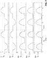
- exemplary waveforms of the detection signal DS1 are shown with reference to the cases in which no arcing phenomena are present and arcing phenomena are present in the electric line 100.
- the current sensor 311 comprises a current transformer provided with a magnetic core 3111 and a secondary winding 3112 advantageously wound around said magnetic core.
- the magnetic core 3111 is shaped as a toroid and is made of a high magnetic permeability material (e.g. cold-rolled grain oriented steel).
- the transformer 311 is arranged in such a way that a conductor of the electric line 100 passes through the magnetic core 3111 so as to form the primary winding of said transformer.
- the first current sensing stage 31 comprises an output circuit section 312 electrically connected in cascade to the first current sensor 311 and configured to provide in output the first preliminary detection signal PDS1 (preferably a voltage signal) indicative of the behavior of the detected line current IL.
- the output circuit section 312 comprises a resistive circuit electrically connected to the secondary winding 3112 of the transformer 311, e.g. a shunt-resistor connected between a terminal of the secondary winding and the ground in such a way to receive a current circulating along the secondary winding 3112 and generate the voltage detection signal PDS1.
- the first processing stage 32 comprises a rectifier 321 electrically connected in cascade with the first current sensing stage 31.
- the rectifier 321 receives and rectifies the first preliminary detection signal PDS1, which is provided in output by the first current sensing stage 31, and provides in output a second preliminary detection signal PDS2 indicative of the behavior (in amplitude) of the line current IL.
- FIG 7 exemplary waveforms of the detection signals PDS1, PDS2 are shown (arcing phenomena are present in the electric line 100).
- the detection signal PDS2 is preferably a voltage signal having a waveform substantially corresponding to the rectified waveform of the detection signals PDS1.
- the rectifier 321 comprises an electronic circuit including an operational amplifier 3210 arranged in a known manner to provide above-described rectification functionalities.
- the operational amplifier 3210 may have the non-inverting input electrically connected to ground, the inverting input electrically connected to the output of the first current sensing stage 31 through a resistive network 3211 and the output electrically connected to the inverting input through a feedback network 3212 including one or more rectifying diodes.
- the first processing stage 32 comprises a first amplifier 322 electrically connected in cascade with the rectifier 321.
- the first amplifier 322 receives and amplifies the second preliminary detection signal PDS2 and provides in output a third preliminary detection signal PDS3 indicative of the behavior of the line current IL.
- FIG 7 exemplary waveforms of the detection signals PDS2, PDS3 are shown (arcing phenomena are present in the electric line 100).
- the detection signal PDS3 is preferably a voltage signal having a waveform substantially corresponding to the waveform of the detection signals PDS2 but with an amplified amplitude.
- the amplifier 322 comprises an electronic circuit including an operational amplifier 3220 arranged in a known manner (e.g. in a non-inverting configuration) to provide above-described amplification functionalities.
- the operational amplifier 3220 may have the non-inverting input electrically connected to the output of the rectifier 321, the inverting input electrically connected to ground through a resistive network 3221 and the output electrically connected to the inverting input through a resistive network 3222.
- the first processing stage 32 comprises a first filter 323 electrically connected in cascade with the first amplifier 322.
- the first filter 323 receives and performs a low-frequency band filtering of the third preliminary detection signal PDS3 and provides in output a fourth preliminary detection signal PDS4 indicative of the behavior of the low-frequency components of the line current IL.
- exemplary waveforms of the detection signals PDS3, PDS4 are shown (arcing phenomena are present in the electric line 100). It will be noticed that the exemplary detection signal PDS4 shown in figure 7 has a base frequency of about twice the mains frequency (e.g. 60 Hz).
- the detection signal PDS4 is preferably a voltage signal having a waveform quite similar to the waveform of the detection signal PDS3 as it includes the low-frequency components of this latter.
- the first filter 323 comprises an electronic circuit formed by a RC low-pass filter arranged in a known manner to provide the above-described filtering functionalities.
- the first processing stage 32 comprises a converter 324 electrically connected in cascade with the first filter 323.
- the converter 324 comprises a peripheral component (which may be of known type) of the microcontroller 20 as shown in figure 2 .
- the converter 324 may comprise a stand-alone electronic device or circuit of known type operatively coupled to the first filter 323 and the controller 20.
- the second detection module 4 comprises a second current stage 41 and a second processing stage 42 electrically connected in cascade with said second current sensing stage.
- the second current sensing stage 41 comprises a second current sensor 411 (distinct from the first current sensor 311) operatively coupled to a conductor L of the electric line 100 to detect the line current IL.
- the second current sensing stage 41 provides in output a fifth preliminary detection signal PDS5 indicative of the behavior (in amplitude) of the high-frequency components of the line current IL whereas the second processing stage 42 receives and processes the fifth preliminary detection signal PDS5 and provides in output the second detection signal DS2 indicative of the behavior of the high-frequency components of the line current IL.
- Exemplary waveforms of the detection signal PDS5 and of the detection signal DS2 are shown in figure 8 (presence of arcing phenomena in the electric line 100).
- the current sensor 411 comprises a current transformer provided with a magnetic core 4111 and a secondary winding 4112 advantageously wound around said magnetic core 411.
- the magnetic core 4111 is shaped as a toroid and is made of low magnetic permeability material suitable to work at high frequencies (e.g. ferrite or iron powder).
- the transformer 411 is arranged in such a way that a conductor of the electric line 100 passes through the magnetic core 4111 so as to form the primary winding of said transformer.
- the second current sensing stage 41 comprises an output circuit section 412 electrically connected in cascade to the second current sensor 411 and configured to provide in output the fifth preliminary detection signal PDS5 (preferably a voltage signal) indicative of the behavior of the high-frequency components of the detected line current IL.
- PDS5 preferably a voltage signal
- the output circuit section 412 comprises passive analog circuitry connected to the secondary winding 4112 of the transformer 411 (e.g. a parallel of a resistor and a capacitor connected between a terminal of the secondary winding and the ground) in such a way to form a RLC circuit in cooperation with the secondary winding 4112 of the transformer (which provides a given inductance).
- a RLC circuit resonates at high-frequencies (e.g. 10 MHz) and provides in output the voltage detection signal PDS5.
- the second processing stage 42 comprises a second amplifier 421, electrically connected in cascade with the second current sensing stage 41, and a second filter 422, electrically connected in cascade with the second amplifier 421.
- the second amplifier 421 receives and amplifies the fifth preliminary detection signal PDS5 and provides in output a detection signal PDS6 (not shown) indicative of the behavior of the high-frequency components of the line current IL.
- the second filter 422 receives the detection signal PDS6 and provides in output the detection signals DS2 ( figure 8 ).
- the detection signal DS2 is preferably a voltage signal having a waveform similar to the waveform of the preliminary detection signals PDS5 but with a cleaner behavior, an amplified amplitude and oscillating about a reference offset level RS.
- the amplifier 421 comprises an electronic circuit including an operation amplifier 4210 arranged in a known manner (e.g. in a Sallen-Key configuration).
- the operational amplifier 4210 may have the non-inverting input electrically connected to an output of the current sensing stage 41 through a RC network 4211 and the output electrically connected to the inverting input through a RC network 4212 and to the non-inverting input through the resistive network 4213.
- the second filter 422 comprises an electronic circuit formed by a RC low-pass filter arranged in a known manner to filter very high-frequency components of the line current IL.
- said RC low-pass filter may have a cut-off frequency of about 28 MHz.
- the comparison module 5 compares the second detection signal DS2 with different first and second threshold levels that may be conveniently centered about the reference offset level RS (e.g. RS+ ⁇ V, RS- ⁇ V, e.g. with a ⁇ V value about 10 mV).
- RS reference offset level
- the comparison module 5 provides in output:
- the comparison module 5 comprises an electronic circuit including an operational amplifier arranged in a known manner (e.g. in a Schmitt Trigger configuration) to provide above-described comparison functionalities.
- FIG 8 an exemplary waveform of the logic signal LS is shown (arcing phenomena are present in the electric line 100). It will be noticed that the exemplary logic signal LS has a frequency in the order of 10 MHz.
- the third detection module 6 is adapted to provide a third detection signal DS3 formed by a sequence of count values N1.
- the subsequent count values N1 are provided with a constant time frequency conveniently corresponding to the sampling frequency adopted by the controller 20.
- Ts a sampling period
- the controller 20 e.g. the same sampling period of the converter 324 described above.
- each count value N1 is indicative of the number of level transitions of the logic signal LS in a corresponding time interval Ts.
- each count value N1 is in practice indicative of the number of oscillations of the second detection signal DS2, which have an amplitude sufficient to cross at least a threshold level RS+ ⁇ V, RS- ⁇ V in a corresponding time interval Ts.
- exemplary waveforms of the detection signal DS3 are shown with reference to the cases in which no arcing phenomena are present and arcing phenomena are present in the electric line 100. As it is evident, the third detection signal DS3 shows quite different behaviors when arcing phenomena are present or not.
- the third detection module 6 comprises a first counter 61 adapted to detect and count the level transitions of the logic signal LS.
- the first counter 61 is formed by a peripheral component (which may be of known type) of the microcontroller 20 as shown in figure 2 .
- the first counter 61 may comprise a stand-alone electronic device or circuit of known type operatively coupled to the comparison module 5 and the controller 20.
- the first counter 61 is a timer clocked by the logic signal LS.
- the third detection module 6 comprises first data processing resources 62 interacting with the first counter 61.
- the data processing resources 62 are formed by a data processing component (which may be of known type) of the microcontroller 20, for example a CPU component capable of executing suitable stored software instructions to provide the functionalities described below.
- a data processing component which may be of known type
- the microcontroller 20 for example a CPU component capable of executing suitable stored software instructions to provide the functionalities described below.
- the first counter 61 receives the logic signal LS and detects and counts the level transitions of said logic signal (e.g. only the transitions from the "low” logic level LS2 to the "high” logic level LS1).
- the first counter 61 increases a count value saved in a first memory location MEM1 (e.g. comprised in said first counter) each time a level transition of the logic signal LS is detected.
- the data processing resources 62 copy the count value N1 saved in the first memory location MEM1 into a second memory location MEM2 and reset the first memory location MEM1.
- the count value N1 saved in the second memory location MEM2 is made available in output by the data processing resources 62 during the following time interval Ts before being overwritten by a subsequent count value. In this way, the data processing resources 62 provide in output the third detection signal DS3 formed by a sequence of count values N1.
- the third detection module 6 comprises a first interrupt generator 63 adapted to detect the level transitions of the logic signals LS and generate a first interrupt signal INT1 each time a level transition of the logic signal LS is detected.
- the interrupt generator 63 is formed by a peripheral component (which may be of known type) of the microcontroller 20 as shown in figure 2 .
- the interrupt generator 63 may comprise a stand-alone electronic device or circuit of known type operatively coupled to the comparison module 5 and the controller 20.
- the interrupt generator 63 is a I/O port receiving the logic signal LS.
- the third detection module 6 comprises second data processing resources 65 interacting with the interrupt generator 63.
- the data processing resources 65 are formed by a data processing component (which may be of known type) of the microcontroller 20, for example a CPU component capable of executing suitable stored software instructions to provide the functionalities described below.
- the interrupt generator 63 receives the logic signal LS and detects the level transitions of the logic signal LS (e.g. only the transitions from the "low” logic level LS2 to the "high” logic level LS1).
- the interrupt generator 63 generates an interrupt signal INT1 each time a level transition of the logic signal LS is detected.
- the data processing resources 65 receive and count the interrupt signals INT1 generated by the interrupt generator 63 and increase a count value saved in a third memory location M3 each time an interrupt signal INT1 is received.
- the data processing resources 65 copy the count value N1 saved in the third memory location MEM3 into a fourth memory location MEM4 and reset the third memory location MEM3.
- the count value N1 saved in the fourth memory location MEM4 is made available in output by the data processing resources 65 during the following time interval Ts before being overwritten by a subsequent count value.
- the data processing resources 62 provide in output the third detection signal DS3 formed by a sequence of count values N1.
- the third detection module 6 is adapted to provide a third detection signal DS3 formed by a sequence of logic values N2.
- the subsequent logic values N2 may conventionally take a "low” logic level (e.g. 0) or a "high” logic level (e.g. 1) and are provided with a constant time frequency conveniently corresponding to the sampling frequency adopted by the controller 20.
- two subsequent logic values N2 are separated by a constant time interval Ts that conveniently corresponds to the sampling period adopted by the controller 20.
- each logic value N2 is indicative of whether at least a level transition of the logic signal LS occurred in a corresponding time interval Ts.
- Each logic value N2 is in practice indicative of the fact that at least an oscillation of the second detection signal DS2, which has an amplitude sufficient to cross at least a threshold level RS+ ⁇ V, RS- ⁇ V, occurred in a corresponding time interval Ts.
- a logic value N2 at a "high” logic level may indicate that at least a level transition of the logic signal LS occurred in a corresponding time interval Ts whereas a logic value N2 at a "low” logic level may indicate that no level transitions of the logic signal LS occurred in the corresponding time interval Ts.
- exemplary waveforms of the detection signal DS3 are shown with reference to the cases in which no arcing phenomena are present and arcing phenomena are present in the electric line 100. As it is evident, the third detection signal DS3 shows quite different behaviors when arcing phenomena are present or not present.
- the third detection module 6 comprises a second interrupt generator 66 to detect the level transitions of the logic signal LS and generate a second interrupt signal INT2 in response to a detected level transition of the logic signal LS.
- the interrupt generator 66 is formed by a peripheral component (which may be of known type) of the microcontroller 20 as shown in figure 2 .
- the interrupt generator 66 may comprise a stand-alone electronic device or circuit of known type operatively coupled to the comparison module 5 and the controller 20.
- the interrupt generator 66 is a I/O port receiving the logic signal LS.
- the third detection module 6 comprises third data processing resources 67 interacting with the interrupt generator 66.
- the data processing resources 67 are formed by a data processing component (which may be of known type) of the microcontroller 20, for example a CPU component capable of executing suitable stored software instructions to provide the functionalities described below.
- a data processing component which may be of known type
- the microcontroller 20 for example a CPU component capable of executing suitable stored software instructions to provide the functionalities described below.
- the data processing resources 67 send a start signal START to the interrupt generator 66 in such a way that said interrupt generator is enabled to detect the level transitions of the logic signal LS.
- the interrupt generator 66 receives the logic signal LS, detects a level transition of the logic signal LS and generates an interrupt signal INT2 in response to the detected level transition.
- the data processing resources 67 send a stop signal STOP to the interrupt generator 63 in such a way that said interrupt generator is disabled and update a logic value saved in a fifth memory location MEM5.
- the data processing resources 67 copy the logic value N2 saved in the fifth memory location MEM5 into a sixth memory location MEM6 and reset the fifth memory location MEM5 (e.g. to a "low" logic value).
- the logic value N2 saved in the sixth memory location MEM6 is made available in output by the data processing resources 67 during the following time interval Ts before being overwritten by a subsequent logic value.
- the data processing resources 67 are capable of providing in output a third detection signal DS3 formed by a sequence of equally time-spaced logic values N2.
- each logic value N2 is indicative of the occurrence of at least a level transition of the logic signal LS in a corresponding time interval Ts.
- the determination module 7 is adapted to execute a determination procedure 50 ( figure 12 ) to determine whether arc fault conditions are present in the electric line 100.
- the determination procedure 50 comprises a sequence of steps 501-506 that is repeated for each half period HP of the first detection signal DS 1.
- the determination procedure 50 comprises a step 501 of comparing the first detection signal DS1 with a first predefined threshold value TH1 that may be suitably set according to the needs.
- such a comparison step allows to identify for each half period HP of the first detection signal DS1, two consecutive time windows in which the first detections signal DS1 is respectively higher and lower than the first predefined threshold value TH1.
- the determination procedure 50 comprises a step 502 of comparing the third detection signal DS3 with a second predefined threshold value TH2 that may be suitably set according to the needs.
- the determination procedure 50 comprises the step 503 of detecting, for the third detection signal DS3, a first number M1 of consecutive count values N1 or logic values N2, which are higher or equal than the second threshold value TH2, and the step 504 of detecting, for the third detection signal DS3, a second number M2 of consecutive count values N1 or logic values N2, which are lower than the second threshold value TH2.
- the determination procedure 50 comprises the step 505 of checking whether the following first condition is verified:
- the determination procedure 50 comprises the step 506 of checking whether the following second condition is verified:
- the determination procedure 50 comprises the step of repeating the sequence of steps 501-506 described above for the following half-period.
- the on-going half-period is considered as a half-period in which no relevant arcing phenomena occur.
- the determination procedure 50 comprises the step of repeating the sequence of steps 501-506 described above for the following half-period.
- the on-going half-period is considered as a half-period in which relevant arcing phenomena occur.
- the determination procedure 50 comprises the step 507 of detecting a third number M3 of half-periods of the first detection signal DS1 for which the above-described first and second conditions occur.
- the determination procedure 50 comprises the step 508 of providing in output a trip signal TS for the tripping unit 12 to activate this latter to interrupt the electric line 100.
- the above mentioned determination procedure 50 allows checking whether high-frequency noise along the electric line is generated by arcing phenomena or by innocuous sources.
- the determination module 7 is formed by a data processing component (which may be of known type) of the microcontroller 20, for example a CPU component capable of executing suitable stored software instructions to provide the above-described functionalities.
- a data processing component which may be of known type
- the microcontroller 20 for example a CPU component capable of executing suitable stored software instructions to provide the above-described functionalities.
- the electronic protection device 1 provides reliable and efficient arc fault detection and determination functionalities.
- the electronic protection device 1 can be easily and cheaply produced at industrial level, e.g. as said arc fault detection and determination arrangement can be realized without expensive electronic components.
- the electronic protection device 1 has a compact structure with a size similar to currently available electronic protection devices.
- the electronic protection device 1 has proven to be easy to industrially manufacture, at competitive costs with respect to currently available electronic protection devices.
Abstract
Description
- The present invention relates to an electronic protection device for low voltage (LV) electric lines.
- As is known, an electronic protection device for a LV electric line generally consists in a circuit breaker equipped with an electronic control unit typically including at least a microcontroller.
- An electronic protection device is normally operatively associated with the conductors of an electric line to interrupt the line current flowing along this latter in case of fault conditions. Typical fault conditions include, for example, ground fault conditions, over-voltage conditions, over-current conditions, arc fault conditions and the like.
- Among the above-mentioned possible fault conditions of the electric line, arc fault conditions are of relevant practical interest.
- As is known, arcing phenomena occur quite often in an electric line as they are mainly due to the formation of a ionized gas currents between two conductive elements of the electric line at different voltage potentials, e.g. two electric contacts, two conductors, a conductor and the ground, etc.
- In most cases (e.g. when generated in domestic switches or in DC motors with brushes in domestic appliances), arcing phenomena are substantially innocuous and do not require the intervention of the electronic protection device to interrupt the electric line.
- However, when they are particularly frequent, long-lasting and intense (e.g. as they are due to faults in the electric lines caused by ageing, poor contacts, mechanical damages of wires, etc.), these phenomena may be quite dangerous as they may rapidly lead to fire or burning events in the electric line with consequent relevant issues in terms of safety.
- In these cases, the electronic protection device is required to promptly intervene to interrupt the electric line.
- For the above reasons, many electronic protection devices of the state of the art are provided with detection arrangements to determine the presence of arc fault conditions along an electric line operatively associated therewith.
- Some electronic protection devices of the state of the art include electronic arrangements configured to analyze the amplitude of broadband noise propagating along the electric line and determine the presence of arc fault conditions on the base of this analysis.
- Currently available solutions of this type are generally easy and cheap to produce at industrial level.
- However, often, these solutions offer poor detection performances due to an excessive sensitivity to noise affecting the electric line (e.g. noise generated by household electrical appliances) as noise is sensed at relatively low frequencies (e.g. below 100 kHz).
- Other electronic protection devices of the state of the art, such as the one described in
US729145B1 , include electronic arrangements configured to perform a more refined analysis of the spectral content of broadband noise propagating along the electric line and determine the presence of arc fault conditions on the base of this analysis. - In general, currently available solutions of this type have proven to be quite reliable and efficient in detecting arc fault conditions.
- However, for the time being, these solutions are quite expensive to produce at industrial level, e.g. due to the use of expensive electronic components, such as log amplifiers.
- In the state of the art, it is thus still quite felt the need for innovative electronic protection devices capable of reliable arc fault detection performances and relatively easy and inexpensive to produce at industrial level.
- In order to respond to this need, the present invention provides an electronic protection device according to the following
claim 1 and the related dependent claims. - In a general definition, the electronic protection device, according to the invention, comprises:
- one or more pairs of electric contacts adapted to be electrically connected with corresponding conductors of the electric line, said electric contacts being operatively coupleable or decoupleable one from another;
- a control unit adapted to control the operation of the electronic protection device;
- a tripping unit and an operating mechanism, said tripping unit actuating said operating mechanism in response to a trip signal received from the control unit, said operating mechanism mechanically interacting with said electric contacts to decouple said electric contacts when it is actuated by the tripping unit.
- The control unit of the electronic protection device of the invention comprises:
- a first detection module adapted to detect the line current flowing along the electric line and provide a first detection signal indicative of the behavior of low-frequency components of said line current;
- a second detection module adapted to detect the line current flowing along the electric line and provide a second detection signal indicative of the behavior of high-frequency components of said line current;
- a comparison module adapted to process said second detection signal and provide a logic signal, the behavior of said logic signal depending on the behavior of said second detection signal;
- a third detection module adapted to process said logic signal and provide a third detection signal indicative of the presence of possible level transitions in said logic signal;
- a determination module adapted to process said first and third detection signals and determine the presence of arc fault conditions in the electric line based on said first and third detection signals, said determination module providing a trip signal for said tripping unit if arc fault conditions are determined.
- Preferably, the first detection module comprises:
- a first current sensing stage comprising a first current sensing device operatively coupled to a conductor of said electric line to detect said line current, said first current sensing stage being adapted to provide a first preliminary detection signal indicative of the behavior of said line current;
- a first processing stage electrically connected in cascade with said first current sensing stage and adapted to process said first preliminary detection signal and provide said first detection signal.
- Preferably, the first processing stage comprises:
- a rectifier electrically connected in cascade with said first current sensing stage, said rectifier being adapted to rectify said first preliminary detection signal and provide a second preliminary detection signal indicative of the behaviour of said line current;
- a first amplifier electrically connected in cascade with said rectifier, said first amplifier being adapted to amplify said second preliminary detection signal and provide a third preliminary detection signal indicative of the behavior of said line current;
- a first filter electrically connected in cascade with said first amplifier, said first filter being adapted to filter said third preliminary detection signal and provide a fourth preliminary detection signal indicative of the behavior of low-frequency components of said line current;
- a converter electrically connected in cascade with said first filter, said converter being adapted to perform an A/D conversion of said fourth preliminary detection signal and provide said first detection signal.
- Preferably, the second detection module comprises:
- a second current sensing stage comprising a second current sensor operatively coupled to a conductor of said electric line to detect said line current, said second current sensing stage being adapted to provide a fifth preliminary detection signal indicative of the behaviour of high-frequency components of said line current;
- a second processing stage electrically connected in cascade with said second current sensing stage and adapted to process said fifth preliminary detection signal and provide said second detection signal.
- Preferably, the processing stage comprises:
- a second amplifier electrically connected in cascade with said second current sensing stage, said second amplifier being adapted to amplify said fifth preliminary detection signal and provide a sixth detection signal indicative of the behavior of high-frequency components of said line current.
- a second filter electrically connected in cascade with said second amplifier, said second filter being adapted to filter said sixth preliminary detection signal (PDS6) and provide said second detection signal.
- According to some embodiments of the invention, said third detection module is adapted to provide a third detection signal formed by a sequence of count values separated by a constant time intervals, each count value being indicative of a number of level transitions of said logic signal occurring within a corresponding time interval.
- In this case, said third detection module may comprise:
- a counter adapted to detect and count the level transitions of said logic signal;
- first data processing resources adapted to acquire a count value indicative of the level transitions of said logic signal counted by said counter within said time interval and provide in output said count value.
- As an alternative, said third detection module may comprise:
- a first interrupt generator adapted to detect the level transitions of said logic signal and provide a first interrupt signal each time a level transition of said logic signal is detected;
- second data processing resources adapted to count the first interrupt signals provided by said first interrupt generator and provide in output a count value indicative of the first interrupt signals counted within said time interval.
- According to other embodiments of the invention, said third detection module is adapted to provide a third detection signal formed by a sequence of logic values separated by constant time intervals, each logic value being indicative of the presence of at least a level transition in said logic signal within a corresponding time interval.
- In this case, said third detection module may comprise:
- a second interrupt generator adapted to detect the level transitions of said logic signal and provide a second interrupt signal if a level transition of said logic signal is detected;
- third data processing resources adapted to enable said second interrupt generator at the beginning of said time interval and disable said second interrupt generator if said second interrupt signal is received from said second interrupt generator, said third data processing resources being adapted to provide a logic value indicative of the receipt of said second interrupt signal within said time interval.
- Preferably, the determination module is adapted to execute a determination procedure comprising the following steps:
- for a half-period of said first detection signal, executing the following steps:
- comparing said first detection signal with a first threshold value;
- comparing said third detection signal with a second threshold value;
- detecting a first number of consecutive count values or logic values higher or equal than said second threshold value for said third detection signal;
- detecting a second number of consecutive count values or logic values lower than said second threshold value for said third detection signal;
- checking whether a first condition occurs, in which a first number of consecutive count values or logic values higher than a third threshold value is detected;
- checking whether a second condition occurs, in which a second number of consecutive count values or logic values higher than a fourth threshold value is detected during a time window of said half-period, in which said first detection signal is lower than said first threshold value;
- detecting a third number of half-periods of said first detection signal for which said first and second conditions simultaneously occur;
- providing in output said trip signal if said third number of half-periods is higher than a fifth threshold value.
- Further characteristics and advantages of the invention will become apparent from the detailed description of exemplary embodiments of the electronic protection device, which is illustrated only by way of non-limitative examples in the accompanying drawings, wherein:
-
Figure 1 is a block diagram of a LV electric line to which an electronic protection device, according to the invention, is operatively associated; -
Figure 2 schematically shows an embodiment of the electronic protection device, according to the invention; -
Figures 3-6 ,9A-9C schematically show different components included in the electronic protection device, according to some embodiments of the invention; -
Figures 7-8 ,10-11 schematically show some detection signals provided in the electronic protection device, according to the invention; and -
Figure 12 schematically shows the operation of a determination module of the control unit of the electronic protection device, according to an embodiment of the invention. - With reference to the cited figures, the present invention relates to an
electronic protection device 1, which, in operation, is associated to a low-voltageelectric line 100. - For the purposes of the present application, the term "low voltage" (LV) relates to operating voltages lower than 1 kV AC and 1.5 kV DC.
- The
electric line 100 comprises one or more phase conductors P and, preferably, a neutral conductor N. - Preferably, the
electric line 100 comprises a single phase conductor P and a neutral conductor N. - In the following, the
electronic protection device 1 will be described with reference to its installation in an electric line having a single phase conductor P and a neutral conductor N for the sake of simplicity only, without intending to limit the scope of the invention. - As the skilled person will certainly understand, the
electric line 100 may, in fact, have different arrangements for its own conductors, according to the needs. - The
electric line 100 is intended to electrically connect an electric power source SC and an electric load LD, which may be of any type. - In operation, the
electronic protection device 1 allows or interrupts a current flow IL between the electric power source SC and the electric load LD, more precisely betweenupstream portions 100A anddownstream portions 100B of theelectric line 100, which are electrically connected with the electric power source SC and the electric load LD, respectively. Conveniently, theelectronic protection device 1 may be arranged according to different configurations. - According to some configurations (typically dedicated to the North American market), the
electronic protection device 1 can take three different operative states, namely a closed state, a tripped state and an open state, during its operating life. - According to other configurations (typically dedicated to the European or other international markets), the
electronic protection device 1 can take two different operative states, namely a closed state and an open state, during its operating life. - When it operates in a closed state, the
electronic protection device 1 allows a current IL to flow along theelectric line 100 between the upstream anddownstream portions - When it operates in a tripped state or open state, the
electronic protection device 1 interrupts the current IL along theelectric line 100, thereby electrically disconnecting the upstream anddownstream portions - Conveniently, the
electronic protection device 1 comprises an outer casing (not shown), preferably made of electrically insulating material, which defines an internal volume to accommodate the components of said electronic protection device. - The
electronic protection device 1 comprises one or more pairs ofelectric contacts 10, including a mobile contact and a fixed contact. - Each pair of
electric contacts 10 is intended to be electrically connected to a corresponding conductor of theelectric line 100 and, in operation, can be mutually coupled or separated. - When the
electric contacts 10 are mutually coupled, theprotection device 1 is in a closed state and an electric current IL can flow along the corresponding conductor of theelectric line 100. When theelectric contacts 10 are decoupled, theprotection device 1 is in a tripped state or open state and an electric current IL is prevented from flowing along the corresponding conductor of theelectric line 100. - The
electric contacts 10 and their electrical connection with the corresponding conductors of theelectric line 100 may be realized in known manners that will not here described in more details for the sake of brevity. - Additionally, the skilled person will certainly understand that, in operation, the pairs of
electric contacts 10 of the electronic protection device are all operated in a coordinated manner in a coupled state or in a decoupled state for obvious purposes of electrical continuity and current balancing. - The
electric protection device 1 comprises anoperating mechanism 11 operatively coupled with the electric contacts 10 (in particular with the mobile contacts thereof) and mechanically interacting with these latter. - The
electric protection device 1 comprises a trippingunit 12 adapted to mechanically actuate theoperating mechanism 11. - In operation, upon receiving a trip signal TS, the tripping
unit 12 actuates theoperating mechanism 11 to decouple theelectric contacts 10, thereby carrying out a tripping manoeuver of the electronic protection device. - Preferably, the tripping
unit 12 comprises an electromagnetic actuator. - Preferably, the tripping
unit 12 is fed by theelectric line 100 through a power supply unit (not shown) of the electronic protection device. - The
electric protection device 1 conveniently comprises other mechanical components, e.g. ahandle 13 operatively coupled with theoperating mechanism 11 and mechanically interacting with this latter. - The
handle 13 is movable (preferably around a suitable rotation axis) between two or three operating positions (depending on the configuration of the electronic protection device). - The
handle 13 may be actuated by theoperating mechanism 11, by a user or by external equipment during a tripping or opening maneuver of the electronic protection device. - The
handle 13 may actuate theoperating mechanism 11 in order to couple or decouple or maintain decoupled (depending on the configuration of the electronic protection device) theelectric contacts 10 during an opening manoeuver or a closing maneuver of the electronic protection device. - In general, the
operating mechanism 11, the trippingunit 12 and thehandle 13 may be realized and operatively coupled in known manners that will not here described in more details for the sake of brevity. - The
electronic protection device 1 comprises acontrol unit 2 for controlling the operation of said electronic protection device. - The
control unit 2 comprises acontroller 20, e.g. a microcontroller. - Preferably, the
control unit 2 is fed by theelectric line 100 through a power supply unit (not shown) of the electronic protection device. - The
controller 20 conveniently include data processing resources of digital type, e.g. a CPU capable of executing stored software instructions, peripheral modules and I/O ports to carry out its functionalities, according to the needs. - An important function of the
control unit 2 consists in providing a trip signal TS to activate the trippingunit 12 when fault conditions, which require a tripping manoeuvre of the electronic protection device, are present in theelectric line 100. - Fault conditions may include ground fault conditions, arc fault conditions, over-current conditions, over-voltage conditions, internal fault conditions in the electronic protection device, and so on.
- The
control unit 2 may comprise suitable arrangements (not shown) to detect and determine the presence of ground fault conditions, over-current conditions, over-voltage conditions in theelectric line 100 and/or of internal fault conditions in the electronic protection device. Such arrangements may be of known type and will not here further described for the sake of brevity. - As it will better be illustrated in the following, according to the invention, the
control unit 2 is characterised by an innovative arrangement (references electric line 100. - According to the invention, the
control unit 2 comprises: - a
first detection module 3, which, in operation, detects the line current IL flowing along theelectric line 100 and provides in output a first detection signal DS1. The first detection signal DS1 is indicative of the behavior (in amplitude) of low-frequency components of the line current IL; - a
second detection module 4, which, in operation, detects the line current IL and provides a second detection signal DS2 indicative of the behavior (in amplitude) of high-frequency components of the line current IL; - a
comparison module 5, which, in operation receives and processes the second detection signal DS2 and provides a logic signal LS variable in amplitude between two different logic levels LS1, LS2. The logic signal LS is subject to possible level transitions from a logic level to another depending on the behavior (in amplitude) of the second detection signal DS2; - a
third detection module 6, which, in operation receives and processes the logic signal LS and provides a third detection signal DS3 indicative of the presence of possible level transitions in the logic signal LS; - a
determination module 7, which, in operation receives and processes the first and third detection signals DS1, DS3 and determines the presence of arc fault conditions based on said detection signals. Thedetermination module 7 provides a trip signal TS to thetrip unit 12 to activate this latter, if arc fault conditions are determined. - The above-mentioned detection or
signal processing modules - If they are implemented in analog manner, they will comprise electronic circuits suitably arranged to perform their functionalities. Said electronic circuits may form separated circuit units or may be at least partially integrated in one or more circuit units.
- If they are implemented in a digital manner, they will comprise suitable data processing resources capable of executing software instructions stored in a medium to perform their functionalities.
- The present invention will be now described in more details with reference to embodiments, in which the
detection module 3 is implemented by suitable electronic circuits and peripheral components of themicrocontroller 20, thedetection module 4 and thecomparison module 5 are implemented by suitable electronic circuits, thedetection module 6 is implemented by peripheral components and digital data processing resources of themicrocontroller 20 and thedetermination module 7 is implemented by digital data processing resources of themicrocontroller 20. - This choice is not intended to limit the scope of the invention in any way. Other embodiments, in which one or more of the above-mentioned detection and signal processing modules are differently implemented are possible and fall within the scope of the present invention.
- In the framework of the present invention, the "low-frequency components" of the line current IL identify those current components having a frequency in a neighborhood of the line frequency (e.g. 50Hz) of the
electric line 100. As an example, the low-frequency components of the line current IL may have a frequency in a band of 5 Hz-5 kHz. - In the framework of the present invention, the "high-frequency components" of the line current IL identify those current components having a frequency very higher than the line frequency of the
electric line 100 and very higher than the sampling frequencies (e.g. 20kHz) adopted by themicrocontroller 20 of thecontrol unit 2. Conveniently, the high-frequency components of the line current IL have a frequency in the range of MHz (preferably higher than 1 MHz). As an example, these current components may have a frequency in a band of 10-12 MHz. - According to an embodiment of the invention (
figures 2-6 ), thefirst detection module 3 comprises a firstcurrent stage 31 and afirst processing stage 32 electrically connected in cascade with said first current sensing stage. - Conveniently, the first
current sensing stage 31 comprises a firstcurrent sensor 311 operatively coupled to a conductor L of theelectric line 100 to detect the line current IL. - In operation, the first
current sensing stage 31 provides in output a first preliminary detection signal PDS1 indicative of the behavior (in amplitude) of the line current IL whereas thefirst processing stage 32 receives and processes the first preliminary detection signal PDS1 and provides in output the first detection signal DS1 indicative of the behavior (in amplitude) of low-voltage components of the line current IL. - In
figure 7 , exemplary waveforms for the line current IL and the detection signal PDS1 are shown (arcing phenomena are present in the electric line 100). As illustrated, the detection signal PDS1 is preferably a voltage signal having a waveform substantially following the waveform of the detected line current IL. - In
figure 10 , exemplary waveforms of the detection signal DS1 are shown with reference to the cases in which no arcing phenomena are present and arcing phenomena are present in theelectric line 100. - Preferably, the
current sensor 311 comprises a current transformer provided with amagnetic core 3111 and a secondary winding 3112 advantageously wound around said magnetic core. Preferably, themagnetic core 3111 is shaped as a toroid and is made of a high magnetic permeability material (e.g. cold-rolled grain oriented steel). - The
transformer 311 is arranged in such a way that a conductor of theelectric line 100 passes through themagnetic core 3111 so as to form the primary winding of said transformer. Preferably, the firstcurrent sensing stage 31 comprises anoutput circuit section 312 electrically connected in cascade to the firstcurrent sensor 311 and configured to provide in output the first preliminary detection signal PDS1 (preferably a voltage signal) indicative of the behavior of the detected line current IL. - Preferably, the
output circuit section 312 comprises a resistive circuit electrically connected to the secondary winding 3112 of thetransformer 311, e.g. a shunt-resistor connected between a terminal of the secondary winding and the ground in such a way to receive a current circulating along the secondary winding 3112 and generate the voltage detection signal PDS1. Preferably, thefirst processing stage 32 comprises arectifier 321 electrically connected in cascade with the firstcurrent sensing stage 31. - In operation, the
rectifier 321 receives and rectifies the first preliminary detection signal PDS1, which is provided in output by the firstcurrent sensing stage 31, and provides in output a second preliminary detection signal PDS2 indicative of the behavior (in amplitude) of the line current IL. - In
figure 7 , exemplary waveforms of the detection signals PDS1, PDS2 are shown (arcing phenomena are present in the electric line 100). - As illustrated, the detection signal PDS2 is preferably a voltage signal having a waveform substantially corresponding to the rectified waveform of the detection signals PDS1.
- Preferably, the
rectifier 321 comprises an electronic circuit including anoperational amplifier 3210 arranged in a known manner to provide above-described rectification functionalities. As an example, theoperational amplifier 3210 may have the non-inverting input electrically connected to ground, the inverting input electrically connected to the output of the firstcurrent sensing stage 31 through aresistive network 3211 and the output electrically connected to the inverting input through afeedback network 3212 including one or more rectifying diodes. - Preferably, the
first processing stage 32 comprises afirst amplifier 322 electrically connected in cascade with therectifier 321. - In operation, the
first amplifier 322 receives and amplifies the second preliminary detection signal PDS2 and provides in output a third preliminary detection signal PDS3 indicative of the behavior of the line current IL. - In
figure 7 , exemplary waveforms of the detection signals PDS2, PDS3 are shown (arcing phenomena are present in the electric line 100). - As illustrated, the detection signal PDS3 is preferably a voltage signal having a waveform substantially corresponding to the waveform of the detection signals PDS2 but with an amplified amplitude.
- Preferably, the
amplifier 322 comprises an electronic circuit including anoperational amplifier 3220 arranged in a known manner (e.g. in a non-inverting configuration) to provide above-described amplification functionalities. As an example, theoperational amplifier 3220 may have the non-inverting input electrically connected to the output of therectifier 321, the inverting input electrically connected to ground through aresistive network 3221 and the output electrically connected to the inverting input through aresistive network 3222. Preferably, thefirst processing stage 32 comprises afirst filter 323 electrically connected in cascade with thefirst amplifier 322. - In operation, the
first filter 323 receives and performs a low-frequency band filtering of the third preliminary detection signal PDS3 and provides in output a fourth preliminary detection signal PDS4 indicative of the behavior of the low-frequency components of the line current IL. - In
figure 7 , exemplary waveforms of the detection signals PDS3, PDS4 are shown (arcing phenomena are present in the electric line 100). It will be noticed that the exemplary detection signal PDS4 shown infigure 7 has a base frequency of about twice the mains frequency (e.g. 60 Hz). - As illustrated, the detection signal PDS4 is preferably a voltage signal having a waveform quite similar to the waveform of the detection signal PDS3 as it includes the low-frequency components of this latter.
- Preferably, the
first filter 323 comprises an electronic circuit formed by a RC low-pass filter arranged in a known manner to provide the above-described filtering functionalities. Preferably, thefirst processing stage 32 comprises aconverter 324 electrically connected in cascade with thefirst filter 323. - In operation, the
converter 324 receives and performs an A/D conversion of the fourth preliminary detection signal PDS4 and provides in output the first detection signal DS1 (figure 10 ). It will be noticed that the exemplary detection signal DS1 shown infigure 10 has a frequency of about 50 Hz whereas the sampling frequency adopted by theconverter 324 is in the order of 20 KHz (sampling period Ts = 50 µs). - Preferably, the
converter 324 comprises a peripheral component (which may be of known type) of themicrocontroller 20 as shown infigure 2 . As an alternative, theconverter 324 may comprise a stand-alone electronic device or circuit of known type operatively coupled to thefirst filter 323 and thecontroller 20. - According to an embodiment of the invention (
figures 2-6 ), thesecond detection module 4 comprises a secondcurrent stage 41 and asecond processing stage 42 electrically connected in cascade with said second current sensing stage. - Conveniently, the second
current sensing stage 41 comprises a second current sensor 411 (distinct from the first current sensor 311) operatively coupled to a conductor L of theelectric line 100 to detect the line current IL. - In operation, the second
current sensing stage 41 provides in output a fifth preliminary detection signal PDS5 indicative of the behavior (in amplitude) of the high-frequency components of the line current IL whereas thesecond processing stage 42 receives and processes the fifth preliminary detection signal PDS5 and provides in output the second detection signal DS2 indicative of the behavior of the high-frequency components of the line current IL. - Exemplary waveforms of the detection signal PDS5 and of the detection signal DS2 are shown in
figure 8 (presence of arcing phenomena in the electric line 100). - It will be noticed that these exemplary signals have a frequency in the order of 10 MHz. Preferably, the
current sensor 411 comprises a current transformer provided with amagnetic core 4111 and a secondary winding 4112 advantageously wound around saidmagnetic core 411. - Preferably, the
magnetic core 4111 is shaped as a toroid and is made of low magnetic permeability material suitable to work at high frequencies (e.g. ferrite or iron powder). - The
transformer 411 is arranged in such a way that a conductor of theelectric line 100 passes through themagnetic core 4111 so as to form the primary winding of said transformer. - Preferably, the second
current sensing stage 41 comprises anoutput circuit section 412 electrically connected in cascade to the secondcurrent sensor 411 and configured to provide in output the fifth preliminary detection signal PDS5 (preferably a voltage signal) indicative of the behavior of the high-frequency components of the detected line current IL. - Preferably, the
output circuit section 412 comprises passive analog circuitry connected to the secondary winding 4112 of the transformer 411 (e.g. a parallel of a resistor and a capacitor connected between a terminal of the secondary winding and the ground) in such a way to form a RLC circuit in cooperation with the secondary winding 4112 of the transformer (which provides a given inductance). Such a RLC circuit resonates at high-frequencies (e.g. 10 MHz) and provides in output the voltage detection signal PDS5. - Preferably, the
second processing stage 42 comprises asecond amplifier 421, electrically connected in cascade with the secondcurrent sensing stage 41, and asecond filter 422, electrically connected in cascade with thesecond amplifier 421. - In operation, the
second amplifier 421 receives and amplifies the fifth preliminary detection signal PDS5 and provides in output a detection signal PDS6 (not shown) indicative of the behavior of the high-frequency components of the line current IL. Thesecond filter 422 receives the detection signal PDS6 and provides in output the detection signals DS2 (figure 8 ). - As illustrated, the detection signal DS2 is preferably a voltage signal having a waveform similar to the waveform of the preliminary detection signals PDS5 but with a cleaner behavior, an amplified amplitude and oscillating about a reference offset level RS. Preferably, the
amplifier 421 comprises an electronic circuit including anoperation amplifier 4210 arranged in a known manner (e.g. in a Sallen-Key configuration). - As an example, the
operational amplifier 4210 may have the non-inverting input electrically connected to an output of thecurrent sensing stage 41 through aRC network 4211 and the output electrically connected to the inverting input through aRC network 4212 and to the non-inverting input through theresistive network 4213. - Preferably, the
second filter 422 comprises an electronic circuit formed by a RC low-pass filter arranged in a known manner to filter very high-frequency components of the line current IL. As an example, said RC low-pass filter may have a cut-off frequency of about 28 MHz. - It is evident how the assembly formed by the above-mentioned
RLC filter 412 and low-pass filter 422 substantially operates as a band-pass filter centered about a high-frequency band (e.g. 10-12 MHz). - According to an embodiment of the invention (
figures 2-6 ), thecomparison module 5 compares the second detection signal DS2 with different first and second threshold levels that may be conveniently centered about the reference offset level RS (e.g. RS+ΔV, RS-ΔV, e.g. with a ΔV value about 10 mV). - Conveniently, in operation, the
comparison module 5 provides in output: - a logic signal LS at a conventionally "high" logic level LS1 (e.g. about 3V) as soon as the second detection signal DS2 crosses the first threshold level RS+ΔV and until the second detection signal DS2 crosses the second threshold level RS-ΔV;
- a logic signal LS at a conventionally "low" logic level LS2 (e.g. about 0,2 V) as soon as the second detection signal DS2 crosses the second threshold level RS-ΔV and until the second detection signal DS2 crosses the first threshold level RS+ΔV.
- Preferably, the
comparison module 5 comprises an electronic circuit including an operational amplifier arranged in a known manner (e.g. in a Schmitt Trigger configuration) to provide above-described comparison functionalities. - In
figure 8 , an exemplary waveform of the logic signal LS is shown (arcing phenomena are present in the electric line 100). It will be noticed that the exemplary logic signal LS has a frequency in the order of 10 MHz. - According to some embodiments of the invention (
figures 9A ,9B ,10 ), thethird detection module 6 is adapted to provide a third detection signal DS3 formed by a sequence of count values N1. - The subsequent count values N1 are provided with a constant time frequency conveniently corresponding to the sampling frequency adopted by the
controller 20. - In other words, two subsequent count values N1 are separated by a constant time interval Ts that conveniently corresponds to a sampling period (e.g. Ts=50 µs) adopted by the controller 20 (e.g. the same sampling period of the
converter 324 described above). - Conveniently, each count value N1 is indicative of the number of level transitions of the logic signal LS in a corresponding time interval Ts.
- As the number of level transitions of the logic signal LS depends of the behavior of the second detection signal DS2, as illustrated above, each count value N1 is in practice indicative of the number of oscillations of the second detection signal DS2, which have an amplitude sufficient to cross at least a threshold level RS+ΔV, RS-ΔV in a corresponding time interval Ts.
- In
figure 10 , exemplary waveforms of the detection signal DS3 are shown with reference to the cases in which no arcing phenomena are present and arcing phenomena are present in theelectric line 100. As it is evident, the third detection signal DS3 shows quite different behaviors when arcing phenomena are present or not. - According to an embodiment of the invention (
figure 9A ), thethird detection module 6 comprises afirst counter 61 adapted to detect and count the level transitions of the logic signal LS. - Preferably, the
first counter 61 is formed by a peripheral component (which may be of known type) of themicrocontroller 20 as shown infigure 2 . As an alternative, thefirst counter 61 may comprise a stand-alone electronic device or circuit of known type operatively coupled to thecomparison module 5 and thecontroller 20. - Preferably, the
first counter 61 is a timer clocked by the logic signal LS. - According to the above-mentioned embodiment of the invention, the
third detection module 6 comprises firstdata processing resources 62 interacting with thefirst counter 61. - Preferably, the
data processing resources 62 are formed by a data processing component (which may be of known type) of themicrocontroller 20, for example a CPU component capable of executing suitable stored software instructions to provide the functionalities described below. - In operation, the
first counter 61 receives the logic signal LS and detects and counts the level transitions of said logic signal (e.g. only the transitions from the "low" logic level LS2 to the "high" logic level LS1). - The
first counter 61 increases a count value saved in a first memory location MEM1 (e.g. comprised in said first counter) each time a level transition of the logic signal LS is detected. - At the end of each time interval Ts, the
data processing resources 62 copy the count value N1 saved in the first memory location MEM1 into a second memory location MEM2 and reset the first memory location MEM1. The count value N1 saved in the second memory location MEM2 is made available in output by thedata processing resources 62 during the following time interval Ts before being overwritten by a subsequent count value. In this way, thedata processing resources 62 provide in output the third detection signal DS3 formed by a sequence of count values N1. - According to another embodiment of the invention (
figure 9B ), thethird detection module 6 comprises a first interruptgenerator 63 adapted to detect the level transitions of the logic signals LS and generate a first interrupt signal INT1 each time a level transition of the logic signal LS is detected. - Preferably, the interrupt
generator 63 is formed by a peripheral component (which may be of known type) of themicrocontroller 20 as shown infigure 2 . As an alternative, the interruptgenerator 63 may comprise a stand-alone electronic device or circuit of known type operatively coupled to thecomparison module 5 and thecontroller 20. - Preferably, the interrupt
generator 63 is a I/O port receiving the logic signal LS. - According to the above-mentioned embodiment of the invention, the
third detection module 6 comprises seconddata processing resources 65 interacting with the interruptgenerator 63. Preferably, thedata processing resources 65 are formed by a data processing component (which may be of known type) of themicrocontroller 20, for example a CPU component capable of executing suitable stored software instructions to provide the functionalities described below. - In operation, the interrupt
generator 63 receives the logic signal LS and detects the level transitions of the logic signal LS (e.g. only the transitions from the "low" logic level LS2 to the "high" logic level LS1). - The interrupt
generator 63 generates an interrupt signal INT1 each time a level transition of the logic signal LS is detected. - The
data processing resources 65 receive and count the interrupt signals INT1 generated by the interruptgenerator 63 and increase a count value saved in a third memory location M3 each time an interrupt signal INT1 is received. - At the end of each time interval Ts, the
data processing resources 65 copy the count value N1 saved in the third memory location MEM3 into a fourth memory location MEM4 and reset the third memory location MEM3. The count value N1 saved in the fourth memory location MEM4 is made available in output by thedata processing resources 65 during the following time interval Ts before being overwritten by a subsequent count value. In this way, thedata processing resources 62 provide in output the third detection signal DS3 formed by a sequence of count values N1. - According to some embodiments of the invention (
figures 9C ,11 ), thethird detection module 6 is adapted to provide a third detection signal DS3 formed by a sequence of logic values N2. The subsequent logic values N2 may conventionally take a "low" logic level (e.g. 0) or a "high" logic level (e.g. 1) and are provided with a constant time frequency conveniently corresponding to the sampling frequency adopted by thecontroller 20. - In other words, two subsequent logic values N2 are separated by a constant time interval Ts that conveniently corresponds to the sampling period adopted by the
controller 20. - Conveniently, each logic value N2 is indicative of whether at least a level transition of the logic signal LS occurred in a corresponding time interval Ts. Each logic value N2 is in practice indicative of the fact that at least an oscillation of the second detection signal DS2, which has an amplitude sufficient to cross at least a threshold level RS+ΔV, RS-ΔV, occurred in a corresponding time interval Ts.
- As an example, a logic value N2 at a "high" logic level may indicate that at least a level transition of the logic signal LS occurred in a corresponding time interval Ts whereas a logic value N2 at a "low" logic level may indicate that no level transitions of the logic signal LS occurred in the corresponding time interval Ts.
- In
figure 11 , exemplary waveforms of the detection signal DS3 are shown with reference to the cases in which no arcing phenomena are present and arcing phenomena are present in theelectric line 100. As it is evident, the third detection signal DS3 shows quite different behaviors when arcing phenomena are present or not present. - According to another embodiment of the invention (
figure 9C ), thethird detection module 6 comprises a second interruptgenerator 66 to detect the level transitions of the logic signal LS and generate a second interrupt signal INT2 in response to a detected level transition of the logic signal LS. - Preferably, the interrupt
generator 66 is formed by a peripheral component (which may be of known type) of themicrocontroller 20 as shown infigure 2 . As an alternative, the interruptgenerator 66 may comprise a stand-alone electronic device or circuit of known type operatively coupled to thecomparison module 5 and thecontroller 20. - Preferably, the interrupt
generator 66 is a I/O port receiving the logic signal LS. - According to the above-mentioned embodiment of the invention, the
third detection module 6 comprises thirddata processing resources 67 interacting with the interruptgenerator 66. - Preferably, the
data processing resources 67 are formed by a data processing component (which may be of known type) of themicrocontroller 20, for example a CPU component capable of executing suitable stored software instructions to provide the functionalities described below. - In operation, at the beginning of each time interval Ts, the
data processing resources 67 send a start signal START to the interruptgenerator 66 in such a way that said interrupt generator is enabled to detect the level transitions of the logic signal LS. - The interrupt
generator 66 receives the logic signal LS, detects a level transition of the logic signal LS and generates an interrupt signal INT2 in response to the detected level transition. - As soon as it receives the interrupt signal INT2 from the interrupt
generator 66, thedata processing resources 67 send a stop signal STOP to the interruptgenerator 63 in such a way that said interrupt generator is disabled and update a logic value saved in a fifth memory location MEM5. - At the end of each time interval Ts, the
data processing resources 67 copy the logic value N2 saved in the fifth memory location MEM5 into a sixth memory location MEM6 and reset the fifth memory location MEM5 (e.g. to a "low" logic value). The logic value N2 saved in the sixth memory location MEM6 is made available in output by thedata processing resources 67 during the following time interval Ts before being overwritten by a subsequent logic value. In this way, periodically interacting with the interruptgenerator 66, thedata processing resources 67 are capable of providing in output a third detection signal DS3 formed by a sequence of equally time-spaced logic values N2. - As each interrupt signal INT2 is generated when a level transition of the logic signal LS is detected by the interrupt
generator 63, each logic value N2 is indicative of the occurrence of at least a level transition of the logic signal LS in a corresponding time interval Ts. - According to the above-described embodiments of the invention (
figures 9A ,9B ,9C ,10 ,11 ), thedetermination module 7 is adapted to execute a determination procedure 50 (figure 12 ) to determine whether arc fault conditions are present in theelectric line 100. - Conveniently, the
determination procedure 50 comprises a sequence of steps 501-506 that is repeated for each half period HP of the firstdetection signal DS 1. - Preferably, the
determination procedure 50 comprises astep 501 of comparing the first detection signal DS1 with a first predefined threshold value TH1 that may be suitably set according to the needs. - Normally, such a comparison step allows to identify for each half period HP of the first detection signal DS1, two consecutive time windows in which the first detections signal DS1 is respectively higher and lower than the first predefined threshold value TH1.
- Preferably, the
determination procedure 50 comprises astep 502 of comparing the third detection signal DS3 with a second predefined threshold value TH2 that may be suitably set according to the needs. - Preferably, the
determination procedure 50 comprises thestep 503 of detecting, for the third detection signal DS3, a first number M1 of consecutive count values N1 or logic values N2, which are higher or equal than the second threshold value TH2, and thestep 504 of detecting, for the third detection signal DS3, a second number M2 of consecutive count values N1 or logic values N2, which are lower than the second threshold value TH2. - Preferably, the
determination procedure 50 comprises thestep 505 of checking whether the following first condition is verified: - the first number M1 of consecutive count values N1 or logic values N2 is higher than a third threshold value TH3 that can be suitably set according to the needs.
- Preferably, the
determination procedure 50 comprises thestep 506 of checking whether the following second condition is verified: - the second number M2 of consecutive count values N1 or logic values N2 is higher than a fourth threshold value TH4 that can be suitably set according to the needs; and
- the second number M2 of consecutive count values N1 or logic values N2 is detected during a time window TW of the half-period HP, in which the first detection signal DS1 is lower than the first threshold value TH1.
- If the above-mentioned first and second conditions are not simultaneously verified, the
determination procedure 50 comprises the step of repeating the sequence of steps 501-506 described above for the following half-period. The on-going half-period is considered as a half-period in which no relevant arcing phenomena occur. - If the above-mentioned first and second conditions are simultaneously verified, the
determination procedure 50 comprises the step of repeating the sequence of steps 501-506 described above for the following half-period. The on-going half-period is considered as a half-period in which relevant arcing phenomena occur. - In parallel to the execution of the steps 501-506 for each half-period HP, the
determination procedure 50 comprises thestep 507 of detecting a third number M3 of half-periods of the first detection signal DS1 for which the above-described first and second conditions occur. - If the detected third number M3 of half-periods is higher than a fifth threshold value TH5 that can be suitably set according to the needs, it means that arc fault conditions are determined. In this case, the
determination procedure 50 comprises thestep 508 of providing in output a trip signal TS for the trippingunit 12 to activate this latter to interrupt theelectric line 100. - It is evident from
figures 10-11 that the above-describeddetermination procedure 50 can be successfully implemented for all the above-described embodiments offigures 9A-9C by suitably setting the threshold value TH2. - Additionally, referring again to
figures 10-11 , it is obvious to notice how the above-described first and second conditions of thedetermination procedure 50 are verified if arcing conditions are present, thereby possibly leading to the determination of arc fault conditions. - The above mentioned
determination procedure 50 allows checking whether high-frequency noise along the electric line is generated by arcing phenomena or by innocuous sources. Preferably, thedetermination module 7 is formed by a data processing component (which may be of known type) of themicrocontroller 20, for example a CPU component capable of executing suitable stored software instructions to provide the above-described functionalities. In practice, it has been found that the electronic protection device, according to the invention, fully achieves the intended aim and objects. - The
electronic protection device 1, according to the invention, provides reliable and efficient arc fault detection and determination functionalities. - At the same time, the
electronic protection device 1 can be easily and cheaply produced at industrial level, e.g. as said arc fault detection and determination arrangement can be realized without expensive electronic components. - The
electronic protection device 1 has a compact structure with a size similar to currently available electronic protection devices. - The
electronic protection device 1 has proven to be easy to industrially manufacture, at competitive costs with respect to currently available electronic protection devices.
Claims (12)
- An electronic protection device (1) for a LV electric line (100) including one or more conductors (P, N), comprising:- one or more pairs of electric contacts (10) electrically connectable with corresponding conductors of said electric line and mutually coupleable or decoupleable;- a control unit (2) adapted to control the operation of said electronic protection device, said control unit comprising a first detection module (3) adapted to detect a line current (IL) flowing along said electric line and provide a first detection signal (DS1) indicative of the behavior of low-frequency components of said line current;characterised in that said control unit comprises:- a second detection module (4) adapted to detect a line current (IL) flowing along a said electric line and provide a second detection signal (DS2) indicative of the behavior of high-frequency components of said line current;- a comparison module (5) adapted to process said second detection signal (DS2) and provide a logic signal (LS), the behavior of said logic signal depending on the behavior of said second detection signal;- a third detection module (6) adapted to process said logic signal (LS) and provide a third detection signal (DS3) indicative of the presence of possible level transitions in said logic signal;- a determination module (7) adapted to process said first and third detection signals (DS1, DS3) and determine the presence of arc fault conditions in said electric line, said determination module providing a trip signal (TS) if arc fault conditions are determined.
- Electronic protection device, according to claim 1, characterised in that it comprises a tripping unit (12) and an operating mechanism (11), said tripping unit being adapted to actuate said operating mechanism in response to a trip signal (TS) received from said control unit, said operating mechanism being adapted to mechanically interact with said electric contacts to decouple said electric contacts when said operating mechanism is actuated by said tripping unit.
- Electronic protection device, according to one or more of the previous claims, characterised in that said first detection module (3) comprises:- a first current sensing stage (31) comprising a first current sensor (311) operatively coupled to a conductor of said electric line to detect said line current, said first current sensing stage being adapted to provide a first preliminary detection signal (PDS1) indicative of the behavior of said line current;- a first processing stage (32) electrically connected in cascade with said first current sensing stage (31) and adapted to process said first preliminary detection signal (PDS1) and provide said first detection signal (DS1).
- Electronic protection device, according to claim 3, characterised in that said first processing stage (32) comprises:- a rectifier (321) electrically connected in cascade with said first current sensing stage (31), said rectifier being adapted to rectify said first preliminary detection signal (PDS1) and provide a second preliminary detection signal (PDS2) indicative of the behaviour of said line current;- a first amplifier (322) electrically connected in cascade with said rectifier (321), said first amplifier being adapted to amplify said second preliminary detection signal (PDS2) and provide a third preliminary detection signal (PDS3) indicative of the behaviour of said line current;- a first filter (323) electrically connected in cascade with said first amplifier (322), said first filter being adapted to filter said third preliminary detection signal (PDS3) and provide a fourth preliminary detection signal (PDS4) indicative of the behavior of low-frequency components of said line current;- a converter (324) electrically connected in cascade with said first filter (323), said converter being adapted to perform an A/D conversion of said fourth preliminary detection signal (PDS4) and provide said first detection signal (DS1).
- Electronic protection device, according to one or more of the previous claims, characterised in that said second detection module (4) comprises:- a second current sensing stage (41) comprising a second current sensor (411) operatively coupled to a conductor of said electric line to detect said line current, said second current sensing stage being adapted to provide a fifth preliminary detection signal (PDS5) indicative of the behaviour of high-frequency components of said line current;- a second processing stage (42) electrically connected in cascade with said second current sensing stage (41) and adapted to process said fifth preliminary detection signal (PDS5) and provide said second detection signal (DS2).
- Electronic protection device, according to claim 5, characterised in that said second processing stage (42) comprises:- a second amplifier (421) electrically connected in cascade with said second current sensing stage (41), said second amplifier being adapted to amplify said fifth preliminary detection signal (PDS5) and provide a sixth preliminary detection signal (PDS6) indicative of the behavior of high-frequency components of said line current.- a second filter (422) electrically connected in cascade with said second amplifier, said second filter being adapted to filter said sixth preliminary detection signal (PDS6) and provide said second detection signal (DS2).
- Electronic protection device, according to one or more of the previous claims, characterised in that said third detection module (6) is adapted to provide a third detection signal (DS3) formed by a sequence of count values (N1) separated by a constant time intervals (Ts), each count value being indicative of a number of level transitions of said logic signal (LS) occurring within a corresponding time interval (Ts).
- Electronic protection device, according to claim 7, characterised in that said third detection module (6) comprises:- a counter (61) adapted to detect and count the level transitions of said logic signal (LS);- first data processing resources (62) adapted to acquire a count value (N1) indicative of the level transitions of said logic signal (LS) counted by said counter within said time interval (Ts) and provide in output said count value.
- Electronic protection device, according to claim 7, characterised in that said third detection module (6) comprises:- a first interrupt generator (63) adapted to detect the level transitions of said logic signal (LS) and provide a first interrupt signal (INT1) each time a level transition of said logic signal is detected;- second data processing resources (65) adapted to count the first interrupt signals (INT1) provided by said first interrupt generator and provide in output a count value (N1) indicative of the first interrupt signals (INT1) counted within said time interval (Ts).
- Electronic protection device, according to one or more of the claims from 1 to 6, characterised in that said third detection module (6) is adapted to provide a third detection signal (DS3) formed by a sequence of logic values (N2) separated by constant time intervals (Ts), each logic value being indicative of the presence of at least a level transition in said logic signal (LS) within a corresponding time interval (Ts).
- Electronic protection device, according to claim 10, characterised in that said third detection module (6) comprises:- a second interrupt generator (66) adapted to detect the level transitions of said logic signal (LS) and provide a second interrupt signal (INT2) if a level transition of said logic signal is detected;- third data processing resources (67) adapted to enable said second interrupt generator at the beginning of said time interval (Ts) and disable said second interrupt generator if said second interrupt signal (INT2) is received from said second interrupt generator, said third data processing resources being adapted to provide a logic value (N2) indicative of the receipt of said second interrupt signal within said time interval (Ts).
- Electronic device, according to one of the claims from 7 to 11, characterised in that said determination module (7) is adapted to execute a determination procedure (50) comprising the following steps:- for one or more half-periods (HP) of said first detection signal (DS1), executing the following steps:- comparing (501) said first detection signal (DS1) with a first threshold value (TH1);- comparing (502) said third detection signal (DS3) with a second threshold value (TH2);- detecting (503) a first number (M1) of consecutive count values (N1) or logic values (N2) higher or equal than said second threshold value (TH2) for said third detection signal (DS3);- detecting (504) a second number (M2) of consecutive count values (N1) or logic values (N2) lower than said second threshold value (TH2) for said third detection signal (DS3);- checking (505) whether a first condition occurs, in which a first number (M1) of consecutive count values or logic values (N1, N2) higher than a third threshold value (TH3) is detected;- checking (506) whether a second condition occurs, in which a second number (M2) of consecutive count values or logic values (N1, N2) higher than a fourth threshold value (TH4) is detected during a time window (TW) of said half-period, in which said first detection signal (DS1) is lower than said first threshold value (TH1);- detecting (507) a third number (M3) of half-periods (HP) of said first detection signal (DS1) for which said first and second conditions simultaneously occur;- providing (508) in output said trip signal (TS) if said third number (M3) of half-periods (HP) is higher than a fifth threshold value (TH5).
Priority Applications (4)
| Application Number | Priority Date | Filing Date | Title |
|---|---|---|---|
| EP17164776.1A EP3386051B1 (en) | 2017-04-04 | 2017-04-04 | Electronic protection device for detecting arcing fault |
| CA2999015A CA2999015A1 (en) | 2017-04-04 | 2018-03-23 | Electronic protection device |
| CN201810294730.5A CN108695834B (en) | 2017-04-04 | 2018-04-04 | Electronic protection device |
| US15/945,345 US11018494B2 (en) | 2017-04-04 | 2018-04-04 | Electronic protection device |
Applications Claiming Priority (1)
| Application Number | Priority Date | Filing Date | Title |
|---|---|---|---|
| EP17164776.1A EP3386051B1 (en) | 2017-04-04 | 2017-04-04 | Electronic protection device for detecting arcing fault |
Publications (2)
| Publication Number | Publication Date |
|---|---|
| EP3386051A1 true EP3386051A1 (en) | 2018-10-10 |
| EP3386051B1 EP3386051B1 (en) | 2021-06-23 |
Family
ID=58489246
Family Applications (1)
| Application Number | Title | Priority Date | Filing Date |
|---|---|---|---|
| EP17164776.1A Active EP3386051B1 (en) | 2017-04-04 | 2017-04-04 | Electronic protection device for detecting arcing fault |
Country Status (4)
| Country | Link |
|---|---|
| US (1) | US11018494B2 (en) |
| EP (1) | EP3386051B1 (en) |
| CN (1) | CN108695834B (en) |
| CA (1) | CA2999015A1 (en) |
Cited By (1)
| Publication number | Priority date | Publication date | Assignee | Title |
|---|---|---|---|---|
| EP4040172A1 (en) | 2021-02-08 | 2022-08-10 | ABB Schweiz AG | Arc fault detection circuit and method for detecting an arc fault |
Families Citing this family (2)
| Publication number | Priority date | Publication date | Assignee | Title |
|---|---|---|---|---|
| KR102083600B1 (en) * | 2018-11-19 | 2020-03-02 | 엘에스산전 주식회사 | Elcb(earth leakage circuit breaker) and control method for the elcb |
| US11079424B2 (en) * | 2018-12-07 | 2021-08-03 | Schneider Electric USA, Inc. | Combined low frequency and high frequency current sensor |
Citations (5)
| Publication number | Priority date | Publication date | Assignee | Title |
|---|---|---|---|---|
| US729145A (en) | 1902-12-15 | 1903-05-26 | David j morris | Beer-keg tap. |
| EP1646119A2 (en) * | 2004-09-28 | 2006-04-12 | EATON Corporation | Arc fault circuit interrupter and method of detecting an arc fault |
| US20070252603A1 (en) * | 2006-04-27 | 2007-11-01 | Carlos Restrepo | Systems, devices, and methods for arc fault detection |
| US7864492B2 (en) * | 2006-10-31 | 2011-01-04 | Siemens Industry, Inc. | Systems and methods for arc fault detection |
| US20160187410A1 (en) * | 2014-12-29 | 2016-06-30 | Eaton Corporation | Arc fault detection system and method and circuit interrupter employing same |
Family Cites Families (8)
| Publication number | Priority date | Publication date | Assignee | Title |
|---|---|---|---|---|
| US5729145A (en) | 1992-07-30 | 1998-03-17 | Siemens Energy & Automation, Inc. | Method and apparatus for detecting arcing in AC power systems by monitoring high frequency noise |
| US8054591B2 (en) * | 2008-07-24 | 2011-11-08 | General Electric Company | Arc detection using discrete wavelet transforms |
| CN101369727B (en) * | 2008-10-15 | 2010-12-22 | 中国矿业大学 | Route selection method aiming at electric arc ground fault |
| CN102195275B (en) * | 2011-05-18 | 2013-11-27 | 北京四方继保自动化股份有限公司 | Protecting method of current change rate with self-adaptive output time-delay characteristic |
| CN104283194B (en) * | 2013-07-05 | 2018-08-03 | 通用电气公司 | Circuit with failure protection function |
| CN103715659B (en) * | 2013-12-18 | 2017-01-25 | 青岛海信网络科技股份有限公司 | Vehicle-mounted power supply protective circuit |
| US9797940B2 (en) * | 2014-12-29 | 2017-10-24 | Eaton Corporation | Arc fault detection system and method and circuit interrupter employing same |
| JP6414520B2 (en) * | 2015-07-14 | 2018-10-31 | 株式会社デンソー | Inspection system |
-
2017
- 2017-04-04 EP EP17164776.1A patent/EP3386051B1/en active Active
-
2018
- 2018-03-23 CA CA2999015A patent/CA2999015A1/en not_active Abandoned
- 2018-04-04 CN CN201810294730.5A patent/CN108695834B/en active Active
- 2018-04-04 US US15/945,345 patent/US11018494B2/en active Active
Patent Citations (5)
| Publication number | Priority date | Publication date | Assignee | Title |
|---|---|---|---|---|
| US729145A (en) | 1902-12-15 | 1903-05-26 | David j morris | Beer-keg tap. |
| EP1646119A2 (en) * | 2004-09-28 | 2006-04-12 | EATON Corporation | Arc fault circuit interrupter and method of detecting an arc fault |
| US20070252603A1 (en) * | 2006-04-27 | 2007-11-01 | Carlos Restrepo | Systems, devices, and methods for arc fault detection |
| US7864492B2 (en) * | 2006-10-31 | 2011-01-04 | Siemens Industry, Inc. | Systems and methods for arc fault detection |
| US20160187410A1 (en) * | 2014-12-29 | 2016-06-30 | Eaton Corporation | Arc fault detection system and method and circuit interrupter employing same |
Cited By (1)
| Publication number | Priority date | Publication date | Assignee | Title |
|---|---|---|---|---|
| EP4040172A1 (en) | 2021-02-08 | 2022-08-10 | ABB Schweiz AG | Arc fault detection circuit and method for detecting an arc fault |
Also Published As
| Publication number | Publication date |
|---|---|
| US20180287368A1 (en) | 2018-10-04 |
| CN108695834A (en) | 2018-10-23 |
| CN108695834B (en) | 2021-08-24 |
| US11018494B2 (en) | 2021-05-25 |
| EP3386051B1 (en) | 2021-06-23 |
| CA2999015A1 (en) | 2018-10-04 |
Similar Documents
| Publication | Publication Date | Title |
|---|---|---|
| US11831139B2 (en) | Processor-based circuit interrupting devices | |
| CA2338742C (en) | Arc fault detection system | |
| US11940498B2 (en) | Apparatuses and methods for passive fault monitoring of current sensing devices in protective circuit interrupters | |
| US6414829B1 (en) | Arc fault circuit interrupter | |
| EP2115843B1 (en) | Arc fault circuit interrupter and method of parallel and series arc fault detection | |
| US8743513B2 (en) | Arc fault detector for AC or DC installations | |
| KR101454203B1 (en) | Low current arc detecting system | |
| US11018494B2 (en) | Electronic protection device | |
| KR101823600B1 (en) | Apparatus for detecting arc and method for detecting parallel arc using acr detecing apparatus | |
| EP2577826A2 (en) | An arc fault detector for ac or dc installations | |
| US10886722B2 (en) | Arc fault current detector | |
| Atharparvez et al. | Series arc fault detection using novel signal processing technique | |
| KR101743531B1 (en) | Apparatus for detecting serial arc using high frequency and method thereof | |
| KR101527366B1 (en) | Arc detection circuit by contact failure | |
| US10483055B2 (en) | Programmable arc fault circuit interrupter (AFCI) | |
| CN213125575U (en) | Electronic relay with selectable ground fault protection function | |
| JP5656291B2 (en) | Shut-off device | |
| AU2023200718A1 (en) | A method for protecting a mains against a successive arc fault and a device for performing the claimed method |
Legal Events
| Date | Code | Title | Description |
|---|---|---|---|
| PUAI | Public reference made under article 153(3) epc to a published international application that has entered the european phase |
Free format text: ORIGINAL CODE: 0009012 |
|
| STAA | Information on the status of an ep patent application or granted ep patent |
Free format text: STATUS: THE APPLICATION HAS BEEN PUBLISHED |
|
| AK | Designated contracting states |
Kind code of ref document: A1 Designated state(s): AL AT BE BG CH CY CZ DE DK EE ES FI FR GB GR HR HU IE IS IT LI LT LU LV MC MK MT NL NO PL PT RO RS SE SI SK SM TR |
|
| AX | Request for extension of the european patent |
Extension state: BA ME |
|
| STAA | Information on the status of an ep patent application or granted ep patent |
Free format text: STATUS: REQUEST FOR EXAMINATION WAS MADE |
|
| STAA | Information on the status of an ep patent application or granted ep patent |
Free format text: STATUS: REQUEST FOR EXAMINATION WAS MADE |
|
| 17P | Request for examination filed |
Effective date: 20190328 |
|
| RBV | Designated contracting states (corrected) |
Designated state(s): AL AT BE BG CH CY CZ DE DK EE ES FI FR GB GR HR HU IE IS IT LI LT LU LV MC MK MT NL NO PL PT RO RS SE SI SK SM TR |
|
| REG | Reference to a national code |
Ref country code: DE Ref legal event code: R079 Ref document number: 602017040647 Country of ref document: DE Free format text: PREVIOUS MAIN CLASS: H02H0001000000 Ipc: H03K0021080000 |
|
| GRAP | Despatch of communication of intention to grant a patent |
Free format text: ORIGINAL CODE: EPIDOSNIGR1 |
|
| STAA | Information on the status of an ep patent application or granted ep patent |
Free format text: STATUS: GRANT OF PATENT IS INTENDED |
|
| RIC1 | Information provided on ipc code assigned before grant |
Ipc: H02H 1/00 20060101ALI20210128BHEP Ipc: H02H 3/20 20060101ALI20210128BHEP Ipc: H02H 3/08 20060101ALI20210128BHEP Ipc: G01R 31/12 20200101ALI20210128BHEP Ipc: H02H 3/10 20060101ALI20210128BHEP Ipc: H03K 21/08 20060101AFI20210128BHEP Ipc: H02H 3/16 20060101ALI20210128BHEP |
|
| INTG | Intention to grant announced |
Effective date: 20210217 |
|
| GRAS | Grant fee paid |
Free format text: ORIGINAL CODE: EPIDOSNIGR3 |
|
| GRAA | (expected) grant |
Free format text: ORIGINAL CODE: 0009210 |
|
| STAA | Information on the status of an ep patent application or granted ep patent |
Free format text: STATUS: THE PATENT HAS BEEN GRANTED |
|
| AK | Designated contracting states |
Kind code of ref document: B1 Designated state(s): AL AT BE BG CH CY CZ DE DK EE ES FI FR GB GR HR HU IE IS IT LI LT LU LV MC MK MT NL NO PL PT RO RS SE SI SK SM TR |
|
| REG | Reference to a national code |
Ref country code: GB Ref legal event code: FG4D |
|
| REG | Reference to a national code |
Ref country code: CH Ref legal event code: EP |
|
| REG | Reference to a national code |
Ref country code: DE Ref legal event code: R096 Ref document number: 602017040647 Country of ref document: DE Ref country code: AT Ref legal event code: REF Ref document number: 1405197 Country of ref document: AT Kind code of ref document: T Effective date: 20210715 |
|
| REG | Reference to a national code |
Ref country code: IE Ref legal event code: FG4D |
|
| REG | Reference to a national code |
Ref country code: DE Ref legal event code: R082 Ref document number: 602017040647 Country of ref document: DE |
|
| REG | Reference to a national code |
Ref country code: LT Ref legal event code: MG9D |
|
| PG25 | Lapsed in a contracting state [announced via postgrant information from national office to epo] |
Ref country code: LT Free format text: LAPSE BECAUSE OF FAILURE TO SUBMIT A TRANSLATION OF THE DESCRIPTION OR TO PAY THE FEE WITHIN THE PRESCRIBED TIME-LIMIT Effective date: 20210623 Ref country code: FI Free format text: LAPSE BECAUSE OF FAILURE TO SUBMIT A TRANSLATION OF THE DESCRIPTION OR TO PAY THE FEE WITHIN THE PRESCRIBED TIME-LIMIT Effective date: 20210623 Ref country code: BG Free format text: LAPSE BECAUSE OF FAILURE TO SUBMIT A TRANSLATION OF THE DESCRIPTION OR TO PAY THE FEE WITHIN THE PRESCRIBED TIME-LIMIT Effective date: 20210923 Ref country code: HR Free format text: LAPSE BECAUSE OF FAILURE TO SUBMIT A TRANSLATION OF THE DESCRIPTION OR TO PAY THE FEE WITHIN THE PRESCRIBED TIME-LIMIT Effective date: 20210623 |
|
| REG | Reference to a national code |
Ref country code: AT Ref legal event code: MK05 Ref document number: 1405197 Country of ref document: AT Kind code of ref document: T Effective date: 20210623 |
|
| PG25 | Lapsed in a contracting state [announced via postgrant information from national office to epo] |
Ref country code: LV Free format text: LAPSE BECAUSE OF FAILURE TO SUBMIT A TRANSLATION OF THE DESCRIPTION OR TO PAY THE FEE WITHIN THE PRESCRIBED TIME-LIMIT Effective date: 20210623 Ref country code: GR Free format text: LAPSE BECAUSE OF FAILURE TO SUBMIT A TRANSLATION OF THE DESCRIPTION OR TO PAY THE FEE WITHIN THE PRESCRIBED TIME-LIMIT Effective date: 20210924 Ref country code: RS Free format text: LAPSE BECAUSE OF FAILURE TO SUBMIT A TRANSLATION OF THE DESCRIPTION OR TO PAY THE FEE WITHIN THE PRESCRIBED TIME-LIMIT Effective date: 20210623 Ref country code: SE Free format text: LAPSE BECAUSE OF FAILURE TO SUBMIT A TRANSLATION OF THE DESCRIPTION OR TO PAY THE FEE WITHIN THE PRESCRIBED TIME-LIMIT Effective date: 20210623 Ref country code: NO Free format text: LAPSE BECAUSE OF FAILURE TO SUBMIT A TRANSLATION OF THE DESCRIPTION OR TO PAY THE FEE WITHIN THE PRESCRIBED TIME-LIMIT Effective date: 20210923 |
|
| REG | Reference to a national code |
Ref country code: NL Ref legal event code: MP Effective date: 20210623 |
|
| PG25 | Lapsed in a contracting state [announced via postgrant information from national office to epo] |
Ref country code: SM Free format text: LAPSE BECAUSE OF FAILURE TO SUBMIT A TRANSLATION OF THE DESCRIPTION OR TO PAY THE FEE WITHIN THE PRESCRIBED TIME-LIMIT Effective date: 20210623 Ref country code: SK Free format text: LAPSE BECAUSE OF FAILURE TO SUBMIT A TRANSLATION OF THE DESCRIPTION OR TO PAY THE FEE WITHIN THE PRESCRIBED TIME-LIMIT Effective date: 20210623 Ref country code: EE Free format text: LAPSE BECAUSE OF FAILURE TO SUBMIT A TRANSLATION OF THE DESCRIPTION OR TO PAY THE FEE WITHIN THE PRESCRIBED TIME-LIMIT Effective date: 20210623 Ref country code: CZ Free format text: LAPSE BECAUSE OF FAILURE TO SUBMIT A TRANSLATION OF THE DESCRIPTION OR TO PAY THE FEE WITHIN THE PRESCRIBED TIME-LIMIT Effective date: 20210623 Ref country code: AT Free format text: LAPSE BECAUSE OF FAILURE TO SUBMIT A TRANSLATION OF THE DESCRIPTION OR TO PAY THE FEE WITHIN THE PRESCRIBED TIME-LIMIT Effective date: 20210623 Ref country code: RO Free format text: LAPSE BECAUSE OF FAILURE TO SUBMIT A TRANSLATION OF THE DESCRIPTION OR TO PAY THE FEE WITHIN THE PRESCRIBED TIME-LIMIT Effective date: 20210623 Ref country code: PT Free format text: LAPSE BECAUSE OF FAILURE TO SUBMIT A TRANSLATION OF THE DESCRIPTION OR TO PAY THE FEE WITHIN THE PRESCRIBED TIME-LIMIT Effective date: 20211025 Ref country code: NL Free format text: LAPSE BECAUSE OF FAILURE TO SUBMIT A TRANSLATION OF THE DESCRIPTION OR TO PAY THE FEE WITHIN THE PRESCRIBED TIME-LIMIT Effective date: 20210623 Ref country code: ES Free format text: LAPSE BECAUSE OF FAILURE TO SUBMIT A TRANSLATION OF THE DESCRIPTION OR TO PAY THE FEE WITHIN THE PRESCRIBED TIME-LIMIT Effective date: 20210623 |
|
| PG25 | Lapsed in a contracting state [announced via postgrant information from national office to epo] |
Ref country code: PL Free format text: LAPSE BECAUSE OF FAILURE TO SUBMIT A TRANSLATION OF THE DESCRIPTION OR TO PAY THE FEE WITHIN THE PRESCRIBED TIME-LIMIT Effective date: 20210623 |
|
| REG | Reference to a national code |
Ref country code: DE Ref legal event code: R097 Ref document number: 602017040647 Country of ref document: DE |
|
| PG25 | Lapsed in a contracting state [announced via postgrant information from national office to epo] |
Ref country code: DK Free format text: LAPSE BECAUSE OF FAILURE TO SUBMIT A TRANSLATION OF THE DESCRIPTION OR TO PAY THE FEE WITHIN THE PRESCRIBED TIME-LIMIT Effective date: 20210623 |
|
| PLBE | No opposition filed within time limit |
Free format text: ORIGINAL CODE: 0009261 |
|
| STAA | Information on the status of an ep patent application or granted ep patent |
Free format text: STATUS: NO OPPOSITION FILED WITHIN TIME LIMIT |
|
| 26N | No opposition filed |
Effective date: 20220324 |
|
| PG25 | Lapsed in a contracting state [announced via postgrant information from national office to epo] |
Ref country code: AL Free format text: LAPSE BECAUSE OF FAILURE TO SUBMIT A TRANSLATION OF THE DESCRIPTION OR TO PAY THE FEE WITHIN THE PRESCRIBED TIME-LIMIT Effective date: 20210623 |
|
| REG | Reference to a national code |
Ref country code: CH Ref legal event code: PL |
|
| REG | Reference to a national code |
Ref country code: BE Ref legal event code: MM Effective date: 20220430 |
|
| PG25 | Lapsed in a contracting state [announced via postgrant information from national office to epo] |
Ref country code: MC Free format text: LAPSE BECAUSE OF FAILURE TO SUBMIT A TRANSLATION OF THE DESCRIPTION OR TO PAY THE FEE WITHIN THE PRESCRIBED TIME-LIMIT Effective date: 20210623 Ref country code: LU Free format text: LAPSE BECAUSE OF NON-PAYMENT OF DUE FEES Effective date: 20220404 Ref country code: LI Free format text: LAPSE BECAUSE OF NON-PAYMENT OF DUE FEES Effective date: 20220430 Ref country code: CH Free format text: LAPSE BECAUSE OF NON-PAYMENT OF DUE FEES Effective date: 20220430 |
|
| PG25 | Lapsed in a contracting state [announced via postgrant information from national office to epo] |
Ref country code: BE Free format text: LAPSE BECAUSE OF NON-PAYMENT OF DUE FEES Effective date: 20220430 |
|
| PG25 | Lapsed in a contracting state [announced via postgrant information from national office to epo] |
Ref country code: IE Free format text: LAPSE BECAUSE OF NON-PAYMENT OF DUE FEES Effective date: 20220404 |
|
| PGFP | Annual fee paid to national office [announced via postgrant information from national office to epo] |
Ref country code: IT Payment date: 20230426 Year of fee payment: 7 Ref country code: FR Payment date: 20230424 Year of fee payment: 7 Ref country code: DE Payment date: 20230420 Year of fee payment: 7 |
|
| PGFP | Annual fee paid to national office [announced via postgrant information from national office to epo] |
Ref country code: GB Payment date: 20230419 Year of fee payment: 7 |
|
| PG25 | Lapsed in a contracting state [announced via postgrant information from national office to epo] |
Ref country code: HU Free format text: LAPSE BECAUSE OF FAILURE TO SUBMIT A TRANSLATION OF THE DESCRIPTION OR TO PAY THE FEE WITHIN THE PRESCRIBED TIME-LIMIT; INVALID AB INITIO Effective date: 20170404 |