EP3386004A1 - Secondary battery - Google Patents
Secondary battery Download PDFInfo
- Publication number
- EP3386004A1 EP3386004A1 EP18162007.1A EP18162007A EP3386004A1 EP 3386004 A1 EP3386004 A1 EP 3386004A1 EP 18162007 A EP18162007 A EP 18162007A EP 3386004 A1 EP3386004 A1 EP 3386004A1
- Authority
- EP
- European Patent Office
- Prior art keywords
- secondary battery
- main
- curve
- battery according
- folding
- Prior art date
- Legal status (The legal status is an assumption and is not a legal conclusion. Google has not performed a legal analysis and makes no representation as to the accuracy of the status listed.)
- Granted
Links
Images



Classifications
-
- H—ELECTRICITY
- H01—ELECTRIC ELEMENTS
- H01M—PROCESSES OR MEANS, e.g. BATTERIES, FOR THE DIRECT CONVERSION OF CHEMICAL ENERGY INTO ELECTRICAL ENERGY
- H01M10/00—Secondary cells; Manufacture thereof
- H01M10/04—Construction or manufacture in general
-
- H—ELECTRICITY
- H01—ELECTRIC ELEMENTS
- H01M—PROCESSES OR MEANS, e.g. BATTERIES, FOR THE DIRECT CONVERSION OF CHEMICAL ENERGY INTO ELECTRICAL ENERGY
- H01M10/00—Secondary cells; Manufacture thereof
- H01M10/04—Construction or manufacture in general
- H01M10/0431—Cells with wound or folded electrodes
-
- H—ELECTRICITY
- H01—ELECTRIC ELEMENTS
- H01M—PROCESSES OR MEANS, e.g. BATTERIES, FOR THE DIRECT CONVERSION OF CHEMICAL ENERGY INTO ELECTRICAL ENERGY
- H01M50/00—Constructional details or processes of manufacture of the non-active parts of electrochemical cells other than fuel cells, e.g. hybrid cells
- H01M50/10—Primary casings; Jackets or wrappings
- H01M50/147—Lids or covers
- H01M50/148—Lids or covers characterised by their shape
- H01M50/15—Lids or covers characterised by their shape for prismatic or rectangular cells
-
- H—ELECTRICITY
- H01—ELECTRIC ELEMENTS
- H01M—PROCESSES OR MEANS, e.g. BATTERIES, FOR THE DIRECT CONVERSION OF CHEMICAL ENERGY INTO ELECTRICAL ENERGY
- H01M50/00—Constructional details or processes of manufacture of the non-active parts of electrochemical cells other than fuel cells, e.g. hybrid cells
- H01M50/10—Primary casings; Jackets or wrappings
- H01M50/172—Arrangements of electric connectors penetrating the casing
- H01M50/174—Arrangements of electric connectors penetrating the casing adapted for the shape of the cells
- H01M50/176—Arrangements of electric connectors penetrating the casing adapted for the shape of the cells for prismatic or rectangular cells
-
- H—ELECTRICITY
- H01—ELECTRIC ELEMENTS
- H01M—PROCESSES OR MEANS, e.g. BATTERIES, FOR THE DIRECT CONVERSION OF CHEMICAL ENERGY INTO ELECTRICAL ENERGY
- H01M50/00—Constructional details or processes of manufacture of the non-active parts of electrochemical cells other than fuel cells, e.g. hybrid cells
- H01M50/50—Current conducting connections for cells or batteries
-
- H—ELECTRICITY
- H01—ELECTRIC ELEMENTS
- H01M—PROCESSES OR MEANS, e.g. BATTERIES, FOR THE DIRECT CONVERSION OF CHEMICAL ENERGY INTO ELECTRICAL ENERGY
- H01M50/00—Constructional details or processes of manufacture of the non-active parts of electrochemical cells other than fuel cells, e.g. hybrid cells
- H01M50/50—Current conducting connections for cells or batteries
- H01M50/528—Fixed electrical connections, i.e. not intended for disconnection
- H01M50/529—Intercell connections through partitions, e.g. in a battery casing
-
- H—ELECTRICITY
- H01—ELECTRIC ELEMENTS
- H01M—PROCESSES OR MEANS, e.g. BATTERIES, FOR THE DIRECT CONVERSION OF CHEMICAL ENERGY INTO ELECTRICAL ENERGY
- H01M50/00—Constructional details or processes of manufacture of the non-active parts of electrochemical cells other than fuel cells, e.g. hybrid cells
- H01M50/50—Current conducting connections for cells or batteries
- H01M50/543—Terminals
- H01M50/547—Terminals characterised by the disposition of the terminals on the cells
- H01M50/55—Terminals characterised by the disposition of the terminals on the cells on the same side of the cell
-
- H—ELECTRICITY
- H01—ELECTRIC ELEMENTS
- H01M—PROCESSES OR MEANS, e.g. BATTERIES, FOR THE DIRECT CONVERSION OF CHEMICAL ENERGY INTO ELECTRICAL ENERGY
- H01M50/00—Constructional details or processes of manufacture of the non-active parts of electrochemical cells other than fuel cells, e.g. hybrid cells
- H01M50/50—Current conducting connections for cells or batteries
- H01M50/543—Terminals
- H01M50/552—Terminals characterised by their shape
- H01M50/553—Terminals adapted for prismatic, pouch or rectangular cells
-
- H—ELECTRICITY
- H01—ELECTRIC ELEMENTS
- H01M—PROCESSES OR MEANS, e.g. BATTERIES, FOR THE DIRECT CONVERSION OF CHEMICAL ENERGY INTO ELECTRICAL ENERGY
- H01M50/00—Constructional details or processes of manufacture of the non-active parts of electrochemical cells other than fuel cells, e.g. hybrid cells
- H01M50/50—Current conducting connections for cells or batteries
- H01M50/572—Means for preventing undesired use or discharge
- H01M50/584—Means for preventing undesired use or discharge for preventing incorrect connections inside or outside the batteries
- H01M50/588—Means for preventing undesired use or discharge for preventing incorrect connections inside or outside the batteries outside the batteries, e.g. incorrect connections of terminals or busbars
-
- H—ELECTRICITY
- H01—ELECTRIC ELEMENTS
- H01M—PROCESSES OR MEANS, e.g. BATTERIES, FOR THE DIRECT CONVERSION OF CHEMICAL ENERGY INTO ELECTRICAL ENERGY
- H01M50/00—Constructional details or processes of manufacture of the non-active parts of electrochemical cells other than fuel cells, e.g. hybrid cells
- H01M50/50—Current conducting connections for cells or batteries
- H01M50/572—Means for preventing undesired use or discharge
- H01M50/584—Means for preventing undesired use or discharge for preventing incorrect connections inside or outside the batteries
- H01M50/59—Means for preventing undesired use or discharge for preventing incorrect connections inside or outside the batteries characterised by the protection means
-
- Y—GENERAL TAGGING OF NEW TECHNOLOGICAL DEVELOPMENTS; GENERAL TAGGING OF CROSS-SECTIONAL TECHNOLOGIES SPANNING OVER SEVERAL SECTIONS OF THE IPC; TECHNICAL SUBJECTS COVERED BY FORMER USPC CROSS-REFERENCE ART COLLECTIONS [XRACs] AND DIGESTS
- Y02—TECHNOLOGIES OR APPLICATIONS FOR MITIGATION OR ADAPTATION AGAINST CLIMATE CHANGE
- Y02E—REDUCTION OF GREENHOUSE GAS [GHG] EMISSIONS, RELATED TO ENERGY GENERATION, TRANSMISSION OR DISTRIBUTION
- Y02E60/00—Enabling technologies; Technologies with a potential or indirect contribution to GHG emissions mitigation
- Y02E60/10—Energy storage using batteries
-
- Y—GENERAL TAGGING OF NEW TECHNOLOGICAL DEVELOPMENTS; GENERAL TAGGING OF CROSS-SECTIONAL TECHNOLOGIES SPANNING OVER SEVERAL SECTIONS OF THE IPC; TECHNICAL SUBJECTS COVERED BY FORMER USPC CROSS-REFERENCE ART COLLECTIONS [XRACs] AND DIGESTS
- Y02—TECHNOLOGIES OR APPLICATIONS FOR MITIGATION OR ADAPTATION AGAINST CLIMATE CHANGE
- Y02P—CLIMATE CHANGE MITIGATION TECHNOLOGIES IN THE PRODUCTION OR PROCESSING OF GOODS
- Y02P70/00—Climate change mitigation technologies in the production process for final industrial or consumer products
- Y02P70/50—Manufacturing or production processes characterised by the final manufactured product
Definitions
- the present invention relates to the field of battery, and particularly relates to a secondary battery.
- the existing secondary battery generally comprises an electrode assembly, a case and a cap plate, the electrode assembly is received in the case, the cap plate is assembled with the case, and an electrode tab of the electrode assembly is electrically connected with an electrode terminal provided on the cap plate.
- the electrode tab In order to ensure a connection strength between the electrode tab and the electrode terminal, the electrode tab needs to have a sufficient large length, and a protecting piece needs to be provided below the electrode tab; in order to reduce the space occupied by the electrode tab, the electrode tab needs to be bent to two layers along an end portion of the protecting piece, which will lead to a contact between the electrode tab and the end portion of the protecting piece; because the electrode tab is thin and a burr is generated in the end portion of the protecting piece during stamping process of the protecting piece, in the production process and the working process of the secondary battery, the electrode tab will be easily pierced by the burr in the end portion of the protecting piece when the secondary battery is dropped, which leads to short circuit of the electrode assembly or circuit interruption of the electrode assembly, and decreases the safety performance
- an object of the present invention is to provide a secondary battery, which can avoid the electrode tab being pierced by an end portion of the protecting piece, and improve the safety performance of the secondary battery.
- the present invention provides a secondary battery which comprises a cap plate, an electrode assembly and a first connecting piece.
- the cap plate comprises a first electrode terminal;
- the electrode assembly comprises a main body, a first electrode tab provided to the main body and a second electrode tab provided to the main body;
- the first connecting piece is connected between the first electrode tab and the first electrode terminal.
- the first electrode tab includes a first connecting portion and a first bending portion, the first connecting portion is provided below the first connecting piece, and the first bending portion connects the main body of the electrode assembly and the first connecting portion.
- the secondary battery further comprises a first protecting piece fixed to a bottom of the first connecting portion.
- the first protecting piece includes a main portion and a first curve portion, the first curve portion is connected with an outer end of the main portion in a width direction and is curved relative to the main portion; the first bending portion is bent downwardly along a curved outer wall of the first curve portion.
- the present invention has the following beneficial effects: in the secondary battery according to the present invention, the first protecting piece is provided with the first curve portion and the first bending portion is bent downwardly along the curved outer wall of the first curve portion, so the first bending portion will not contact a burr in an end portion of the first protecting piece, in a production process and a working process of the secondary battery, the first bending portion will not be pierced by the curved outer wall of the first curve portion, thereby avoiding short circuit of the electrode assembly or circuit interruption of the electrode assembly, improving the safety performance of the secondary battery.
- a secondary battery comprises a cap plate 1, an electrode assembly 2, a first connecting piece 3 and a first protecting piece 4.
- the cap plate 1 comprises a first electrode terminal 11.
- the electrode assembly 2 comprises a main body 21, a first electrode tab 22 and a second electrode tab 23, the first electrode tab 22 and the second electrode tab 23 are provided to the main body 21 and opposite in electrical polarity.
- the first connecting piece 3 is connected in series between the first electrode tab 22 and the first electrode terminal 11.
- the first electrode tab 22 includes a first connecting portion 221 and a first bending portion 222, the first connecting portion 221 is provided below the first connecting piece 3, and the first bending portion 222 connects the main body 21 of the electrode assembly 2 and the first connecting portion 221.
- the first protecting piece 4 is fixed to a bottom of the first connecting portion 221 and includes a main portion 41 and a first curve portion 43, the first curve portion 43 is connected with an outer end of the main portion 41 in a width direction W and is curved relative to the main portion 41.
- the first bending portion 222 is bent downwardly along a curved outer wall of the first curve portion 43.
- the first protecting piece 4 is provided with the first curve portion 43 and the first bending portion 222 is bent downwardly along the curved outer wall of the first curve portion 43, so the first bending portion 222 will not contact a burr in an end portion of the first protecting piece 4, in a production process and a working process of the secondary battery, the first bending portion 222 will not be pierced by the curved outer wall of the first curve portion 43, thereby avoiding short circuit of the electrode assembly 2 or circuit interruption of the electrode assembly 2, improving the safety performance of the secondary battery.
- the cap plate 1 further comprises a second electrode terminal 12 electrically connected with the second electrode tab 23.
- the first protecting piece 4 further includes a first folding portion 42 folded back onto the main portion 41, and the first curve portion 43 connects the main portion 41 and the first folding portion 42, the first folding portion 42, the first curve portion 43 and the main portion 41 form a U-shaped structure.
- a width of the first folding portion 42 is equal to a width of the main portion 41 in the width direction W.
- the U-shaped structure is used to generally describe a shape formed by the first folding portion 42, the first curve portion 43 and the main portion 41, the first folding portion 42 can be flush with the main portion 41 (referring to FIG.
- the width of the first folding portion 42 is equal to the width of the main portion 41 in the width direction W) or shorter than the main portion 41 (referring to FIG. 6 , the width of the first folding portion 42 is smaller than the width of the main portion 41 in the width direction W).
- the first protecting piece 4 further includes a second curve portion 44 and a second folding portion 45, the second curve portion 44 is connected with an inner end of the main portion 41 in the width direction W and is curved relative to the main portion 41; the second folding portion 45 is folded back onto the main portion 41, and the second curve portion 44 connects the main portion 41 and the second folding portion 45; the second folding portion 45, the second curve portion 44 and the main portion 41 form a U-shaped structure, the second folding portion 45 and the first folding portion 42 are positioned at a side of the main portion 41 in an up-down direction U.
- the U-shaped structure is used to generally describe a shape formed by the second folding portion 45, the second curve portion 44 and the main portion 41, the second folding portion 45 can be flush with the main portion 41 or shorter than the main portion 41 (referring to FIG. 6 , a width of the second folding portion 45 is smaller than the width of the main portion 41 the width direction W).
- the first folding portion 42 and the second folding portion 45 are symmetric about a plane formed by the up-down direction U and a length direction L; the first curve portion 43 and the second curve portion 44 are symmetric about the plane formed the up-down direction U and the length direction L.
- the first protecting piece 4 in this symmetric structure can have a foolproof function.
- the secondary battery further comprises a case 5 and an insulating frame 6, the case 5 receives the electrode assembly 2 and is assembled with the cap plate 1, the insulating frame 6 is received in the case 5 and provided below the cap plate 1, the insulating frame 6 includes a base portion 63.
- the main body 21 of the electrode assembly 2 comprises a positive electrode plate, a negative electrode plate and a separator provided between the positive electrode plate and the negative electrode plate, the positive electrode plate, the negative electrode plate and the separator are wound to a flat shape, and an upper surface 211 of the main body 21 formed by winding faces the insulating frame 6.
- first side edges 61 Two ends of the base portion 63 in the length direction L are provided with first side edges 61 extending downwardly, each first side edge 61 abuts on the upper surface 211 of the main body 21 of the electrode assembly 2.
- the first side edges 61 of the insulating frame 6 abut on the upper surface 211 of the main body 21 of the electrode assembly 2, so the first side edges 61 can limit movement of the electrode assembly 2 in the up-down direction U when the secondary battery is vibrated or dropped, thereby avoiding the short circuit of the electrode assembly 2 and improving the safety performance of the secondary battery.
- the electrode assembly 2 is provided as multiple in number, each first side edge 61 abuts on the upper surfaces 211 of the electrode assemblies 2 at the same time.
- a ratio of an area of the upper surface 211 contacted with the first side edges 61 to a total area of the upper surface 211 ranges from 0.1 to 0.4.
- the main body 21 of the electrode assembly 2 is formed by winding the positive electrode plate, the negative electrode plate and the separator, and in order to ensure that the separator completely separates the positive electrode plate and negative electrode plate, edges of the separator need to be beyond the positive electrode plate and the negative electrode plate.
- the upper surface 211 contacted with the first side edges 61 will be subjected to a high pressure when the secondary battery is vibrated or dropped, and the first side edges 61 will bend the separator easily, which will lead to that the separator can not completely separate the positive electrode plate and the negative electrode plate and result in the short circuit of the electrode assembly 2. Therefore, it needs to ensure that the area of the upper surface 211 contacted with the first side edges 61 is large enough, thereby decreasing the pressure on the upper surface 211 exerted by the first side edges 61.
- the base portion 63 is provided with a second side edge 62 extending downwardly, the second side edge 62 is positioned at an outer side of the first curve portion 43 in the width direction W, and the second side edge 62 is positioned between the first electrode tab 22 and the case 5, at least a part of the first bending portion 222 is positioned between the second side edge 62 and the first curve portion 43 in the width direction W.
- the first electrode tabs 22 need to be gathered and then fixed to the first connecting piece 3, so the second side edge 62 and the first curve portion 43 can function for gathering the first bending portions 222 of the first electrode tabs 22, thereby avoiding the movement of the first bending portions 222.
- a rounded corner R is provided in a connecting portion between the base portion 63 and the second side edge 62, and the rounded corner R is formed in an inner wall of the insulating frame 6.
- the first electrode tab 22 is generally provided as multiple layers; the first bending portion 222 is bent downwardly along the curved outer wall of the first curve portion 43, so the first bending portion 222 positioned in the outer side of the curved outer wall will correspondingly forms a curved structure; at this time, if the inner wall of the connecting portion between the base portion 63 and the second side edge 62 has a right-angled structure, the first bending portion 222 positioned in the outer side of the curved outer wall will be easily caught in the right-angled structure and in turn be crushed.
- the rounded corner R is similar to the first bending portion 222 positioned in the outer side of the curved outer wall in shape, so the rounded corner R can limit the first bending portion 222 positioned in the outer side of the curved outer wall and avoid the first bending portion 222 being crushed.
- the first protecting piece 4, the first connecting portion 221 and the first connecting piece 3 are fixed together by ultrasonic welding; an insulating adhesive G is adhered on a surface of the first protecting piece 4 facing the main body 21.
- the insulating adhesive G can avoid contact between the first protecting piece 4 and the main body 21, and prevent short circuit.
Landscapes
- Chemical & Material Sciences (AREA)
- Chemical Kinetics & Catalysis (AREA)
- Electrochemistry (AREA)
- General Chemical & Material Sciences (AREA)
- Engineering & Computer Science (AREA)
- Manufacturing & Machinery (AREA)
- Connection Of Batteries Or Terminals (AREA)
Abstract
Description
- The present application claims priority to Chinese patent application No.
201710223760.2, filed on April 07, 2017 - The present invention relates to the field of battery, and particularly relates to a secondary battery.
- The existing secondary battery generally comprises an electrode assembly, a case and a cap plate, the electrode assembly is received in the case, the cap plate is assembled with the case, and an electrode tab of the electrode assembly is electrically connected with an electrode terminal provided on the cap plate. In order to ensure a connection strength between the electrode tab and the electrode terminal, the electrode tab needs to have a sufficient large length, and a protecting piece needs to be provided below the electrode tab; in order to reduce the space occupied by the electrode tab, the electrode tab needs to be bent to two layers along an end portion of the protecting piece, which will lead to a contact between the electrode tab and the end portion of the protecting piece; because the electrode tab is thin and a burr is generated in the end portion of the protecting piece during stamping process of the protecting piece, in the production process and the working process of the secondary battery, the electrode tab will be easily pierced by the burr in the end portion of the protecting piece when the secondary battery is dropped, which leads to short circuit of the electrode assembly or circuit interruption of the electrode assembly, and decreases the safety performance of the secondary battery.
- In view of the problem existing in the background, an object of the present invention is to provide a secondary battery, which can avoid the electrode tab being pierced by an end portion of the protecting piece, and improve the safety performance of the secondary battery.
- In order to achieve the above object, the present invention provides a secondary battery which comprises a cap plate, an electrode assembly and a first connecting piece. The cap plate comprises a first electrode terminal; the electrode assembly comprises a main body, a first electrode tab provided to the main body and a second electrode tab provided to the main body; the first connecting piece is connected between the first electrode tab and the first electrode terminal. The first electrode tab includes a first connecting portion and a first bending portion, the first connecting portion is provided below the first connecting piece, and the first bending portion connects the main body of the electrode assembly and the first connecting portion. The secondary battery further comprises a first protecting piece fixed to a bottom of the first connecting portion. The first protecting piece includes a main portion and a first curve portion, the first curve portion is connected with an outer end of the main portion in a width direction and is curved relative to the main portion; the first bending portion is bent downwardly along a curved outer wall of the first curve portion.
- The present invention has the following beneficial effects: in the secondary battery according to the present invention, the first protecting piece is provided with the first curve portion and the first bending portion is bent downwardly along the curved outer wall of the first curve portion, so the first bending portion will not contact a burr in an end portion of the first protecting piece, in a production process and a working process of the secondary battery, the first bending portion will not be pierced by the curved outer wall of the first curve portion, thereby avoiding short circuit of the electrode assembly or circuit interruption of the electrode assembly, improving the safety performance of the secondary battery.
-
-
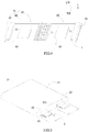
FIG. 1 is a schematic view of a secondary battery according to the present invention. -
FIG. 2 is an enlarged view of a part surrounded by a dotted circle shown inFIG. 1 . -
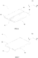
FIG. 3 is another schematic view of the secondary battery according to the present invention. -
FIG. 4 is a schematic view of a cap plate and an insulating frame of the secondary battery according to the present invention. -
FIG. 5 is a schematic view of an electrode assembly, a first connecting piece and a first protecting piece of the secondary battery according to the present invention. -
FIG. 6 is a schematic view of an embodiment of the first protecting piece of the secondary battery according to the present invention. -
FIG. 7 is a schematic view of another embodiment of the first protecting piece of the secondary battery according to the present invention. -
FIG. 8 is a schematic view of still another embodiment of the first protecting piece of the secondary battery according to the present invention. - Reference numerals in figures are represented as follows:
- 1 cap plate
- 11 first electrode terminal
- 12 second electrode terminal
- 2 electrode assembly
- 21 main body
- 211 upper surface
- 22 first electrode tab
- 221 first connecting portion
- 222 first bending portion
- 23 second electrode tab
- 21 main body
- 3 first connecting piece
- 4 first protecting piece
- 41 main portion
- 42 first folding portion
- 43 first curve portion
- 44 second curve portion
- 45 second folding portion
- 5 case
- 6 insulating frame
- 61 first side edge
- 62 second side edge
- 63 base portion
- R rounded corner
- G insulating adhesive
- W width direction
- U up-down direction
- L length direction
- Hereinafter a secondary battery according to the present invention will be described in detail in combination with the figures.
- Referring to
FIGs. 1-8 , a secondary battery according to the present invention comprises acap plate 1, anelectrode assembly 2, a first connectingpiece 3 and a first protectingpiece 4. Thecap plate 1 comprises afirst electrode terminal 11. Theelectrode assembly 2 comprises amain body 21, afirst electrode tab 22 and asecond electrode tab 23, thefirst electrode tab 22 and thesecond electrode tab 23 are provided to themain body 21 and opposite in electrical polarity. The first connectingpiece 3 is connected in series between thefirst electrode tab 22 and thefirst electrode terminal 11. Thefirst electrode tab 22 includes a first connectingportion 221 and afirst bending portion 222, the first connectingportion 221 is provided below the first connectingpiece 3, and thefirst bending portion 222 connects themain body 21 of theelectrode assembly 2 and the first connectingportion 221. The first protectingpiece 4 is fixed to a bottom of the first connectingportion 221 and includes amain portion 41 and afirst curve portion 43, thefirst curve portion 43 is connected with an outer end of themain portion 41 in a width direction W and is curved relative to themain portion 41. Thefirst bending portion 222 is bent downwardly along a curved outer wall of thefirst curve portion 43. - In the secondary battery according to the present invention, the first protecting
piece 4 is provided with thefirst curve portion 43 and thefirst bending portion 222 is bent downwardly along the curved outer wall of thefirst curve portion 43, so thefirst bending portion 222 will not contact a burr in an end portion of the first protectingpiece 4, in a production process and a working process of the secondary battery, thefirst bending portion 222 will not be pierced by the curved outer wall of thefirst curve portion 43, thereby avoiding short circuit of theelectrode assembly 2 or circuit interruption of theelectrode assembly 2, improving the safety performance of the secondary battery. - In the secondary battery according to the present invention, referring to
FIG. 3 , thecap plate 1 further comprises asecond electrode terminal 12 electrically connected with thesecond electrode tab 23. - In the secondary battery according to the present invention, referring to
FIG. 2 ,FIG. 6 and FIG. 7 , the first protectingpiece 4 further includes afirst folding portion 42 folded back onto themain portion 41, and thefirst curve portion 43 connects themain portion 41 and thefirst folding portion 42, thefirst folding portion 42, thefirst curve portion 43 and themain portion 41 form a U-shaped structure. In an embodiment, referring toFIG. 7 , a width of thefirst folding portion 42 is equal to a width of themain portion 41 in the width direction W. The U-shaped structure is used to generally describe a shape formed by thefirst folding portion 42, thefirst curve portion 43 and themain portion 41, thefirst folding portion 42 can be flush with the main portion 41 (referring toFIG. 7 , the width of thefirst folding portion 42 is equal to the width of themain portion 41 in the width direction W) or shorter than the main portion 41 (referring toFIG. 6 , the width of thefirst folding portion 42 is smaller than the width of themain portion 41 in the width direction W). - In the secondary battery according to the present invention, referring to
FIG. 2 andFIG. 6 , thefirst protecting piece 4 further includes asecond curve portion 44 and asecond folding portion 45, thesecond curve portion 44 is connected with an inner end of themain portion 41 in the width direction W and is curved relative to themain portion 41; thesecond folding portion 45 is folded back onto themain portion 41, and thesecond curve portion 44 connects themain portion 41 and thesecond folding portion 45; thesecond folding portion 45, thesecond curve portion 44 and themain portion 41 form a U-shaped structure, thesecond folding portion 45 and thefirst folding portion 42 are positioned at a side of themain portion 41 in an up-down direction U. The U-shaped structure is used to generally describe a shape formed by thesecond folding portion 45, thesecond curve portion 44 and themain portion 41, thesecond folding portion 45 can be flush with themain portion 41 or shorter than the main portion 41 (referring toFIG. 6 , a width of thesecond folding portion 45 is smaller than the width of themain portion 41 the width direction W). - In the secondary battery according to the present invention, referring to
FIG. 6 , thefirst folding portion 42 and thesecond folding portion 45 are symmetric about a plane formed by the up-down direction U and a length direction L; thefirst curve portion 43 and thesecond curve portion 44 are symmetric about the plane formed the up-down direction U and the length direction L. Thefirst protecting piece 4 in this symmetric structure can have a foolproof function. - In the secondary battery according to the present invention, referring to
FIG. 3 , the secondary battery further comprises acase 5 and an insulatingframe 6, thecase 5 receives theelectrode assembly 2 and is assembled with thecap plate 1, the insulatingframe 6 is received in thecase 5 and provided below thecap plate 1, the insulatingframe 6 includes abase portion 63. Referring toFIG. 5 , themain body 21 of theelectrode assembly 2 comprises a positive electrode plate, a negative electrode plate and a separator provided between the positive electrode plate and the negative electrode plate, the positive electrode plate, the negative electrode plate and the separator are wound to a flat shape, and anupper surface 211 of themain body 21 formed by winding faces the insulatingframe 6. Two ends of thebase portion 63 in the length direction L are provided with first side edges 61 extending downwardly, eachfirst side edge 61 abuts on theupper surface 211 of themain body 21 of theelectrode assembly 2. The first side edges 61 of the insulatingframe 6 abut on theupper surface 211 of themain body 21 of theelectrode assembly 2, so the first side edges 61 can limit movement of theelectrode assembly 2 in the up-down direction U when the secondary battery is vibrated or dropped, thereby avoiding the short circuit of theelectrode assembly 2 and improving the safety performance of the secondary battery. - In the secondary battery according to the present invention, referring to
FIG. 1 , theelectrode assembly 2 is provided as multiple in number, eachfirst side edge 61 abuts on theupper surfaces 211 of theelectrode assemblies 2 at the same time. - In the secondary battery according to the present invention, a ratio of an area of the
upper surface 211 contacted with the first side edges 61 to a total area of theupper surface 211 ranges from 0.1 to 0.4. Themain body 21 of theelectrode assembly 2 is formed by winding the positive electrode plate, the negative electrode plate and the separator, and in order to ensure that the separator completely separates the positive electrode plate and negative electrode plate, edges of the separator need to be beyond the positive electrode plate and the negative electrode plate. If the area of theupper surface 211 contacted with the first side edges 61 is too small, theupper surface 211 will be subjected to a high pressure when the secondary battery is vibrated or dropped, and the first side edges 61 will bend the separator easily, which will lead to that the separator can not completely separate the positive electrode plate and the negative electrode plate and result in the short circuit of theelectrode assembly 2. Therefore, it needs to ensure that the area of theupper surface 211 contacted with the first side edges 61 is large enough, thereby decreasing the pressure on theupper surface 211 exerted by the first side edges 61. - In the secondary battery according to the present invention, referring to
FIG. 1 andFIG. 2 , thebase portion 63 is provided with asecond side edge 62 extending downwardly, thesecond side edge 62 is positioned at an outer side of thefirst curve portion 43 in the width direction W, and thesecond side edge 62 is positioned between thefirst electrode tab 22 and thecase 5, at least a part of thefirst bending portion 222 is positioned between thesecond side edge 62 and thefirst curve portion 43 in the width direction W. When a large number ofelectrode assemblies 2 are provided in the secondary battery, thefirst electrode tabs 22 need to be gathered and then fixed to the first connectingpiece 3, so thesecond side edge 62 and thefirst curve portion 43 can function for gathering thefirst bending portions 222 of thefirst electrode tabs 22, thereby avoiding the movement of thefirst bending portions 222. - In the secondary battery according to the present invention, referring to
FIG. 1 andFIG. 2 , a rounded corner R is provided in a connecting portion between thebase portion 63 and thesecond side edge 62, and the rounded corner R is formed in an inner wall of the insulatingframe 6. In order to ensure an overcurrent area, thefirst electrode tab 22 is generally provided as multiple layers; thefirst bending portion 222 is bent downwardly along the curved outer wall of thefirst curve portion 43, so thefirst bending portion 222 positioned in the outer side of the curved outer wall will correspondingly forms a curved structure; at this time, if the inner wall of the connecting portion between thebase portion 63 and thesecond side edge 62 has a right-angled structure, thefirst bending portion 222 positioned in the outer side of the curved outer wall will be easily caught in the right-angled structure and in turn be crushed. The rounded corner R is similar to thefirst bending portion 222 positioned in the outer side of the curved outer wall in shape, so the rounded corner R can limit thefirst bending portion 222 positioned in the outer side of the curved outer wall and avoid thefirst bending portion 222 being crushed. - In the secondary battery according to the present invention, referring to
FIG. 1 andFIG. 2 , thefirst protecting piece 4, the first connectingportion 221 and the first connectingpiece 3 are fixed together by ultrasonic welding; an insulating adhesive G is adhered on a surface of thefirst protecting piece 4 facing themain body 21. In the production process and the working process of the secondary battery, the insulating adhesive G can avoid contact between thefirst protecting piece 4 and themain body 21, and prevent short circuit.
Claims (10)
- A secondary battery, comprising:a cap plate (1) comprising a first electrode terminal (11);an electrode assembly (2) comprising a main body (21), a first electrode tab (22) provided to the main body (21) and a second electrode tab (23) provided to the main body (21); anda first connecting piece (3) connected between the first electrode tab (22) and the first electrode terminal (11);whereinthe first electrode tab (22) includes a first connecting portion (221) and a first bending portion (222), the first connecting portion (221) is provided below the first connecting piece (3), and the first bending portion (222) connects the main body (21) of the electrode assembly (2) and the first connecting portion (221);the secondary battery further comprises a first protecting piece (4) fixed to a bottom of the first connecting portion (221);the first protecting piece (4) includes a main portion (41) and a first curve portion (43), the first curve portion (43) is connected with an outer end of the main portion (41) in a width direction (W) and is curved relative to the main portion (41);the first bending portion (222) is bent downwardly along a curved outer wall of the first curve portion (43).
- The secondary battery according to Claim 1, wherein
the first protecting piece (4) further includes a first folding portion (42) folded back onto the main portion (41), and the first curve portion (43) connects the main portion (41) and the first folding portion (42), the first folding portion (42), the first curve portion (43) and the main portion (41) form a U-shaped structure. - The secondary battery according to Claim 2, wherein
a width of the first folding portion (42) is equal to a width of the main portion (41) in the width direction (W). - The secondary battery according to Claim 2, wherein
the first protecting piece (4) further includes a second curve portion (44) and a second folding portion (45), the second curve portion (44) is connected with an inner end of the main portion (41) in the width direction (W) and is curved relative to the main portion (41);
the second folding portion (45) is folded back onto the main portion (41), and the second curve portion (44) connects the main portion (41) and the second folding portion (45);
the second folding portion (45), the second curve portion (44) and the main portion (41) form a U-shaped structure, the second folding portion (45) and the first folding portion (42) are positioned at a side of the main portion (41) in an up-down direction (U). - The secondary battery according to Claim 4, wherein
the first folding portion (42) and the second folding portion (45) are symmetric about a plane formed by the up-down direction (U) and a length direction (L);
the first curve portion (43) and the second curve portion (44) are symmetric about the plane formed the up-down direction (U) and the length direction (L). - The secondary battery according to Claim 1, wherein
the secondary battery further comprises a case (5) and an insulating frame (6), the case (5) receives the electrode assembly (2) and is assembled with the cap plate (1), the insulating frame (6) is received in the case (5) and provided below the cap plate (1), the insulating frame (6) includes a base portion (63);
the main body (21) of the electrode assembly (2) comprises a positive electrode plate, a negative electrode plate and a separator provided between the positive electrode plate and the negative electrode plate,
the positive electrode plate, the negative electrode plate and the separator are wound to a flat shape, and an upper surface (211) of the main body (21) formed by winding faces the insulating frame (6);
two ends of the base portion (63) in a length direction (L) are provided with first side edges (61) extending downwardly, each first side edge (61) abuts on the upper surface (211) of the main body (21) of the electrode assembly (2). - The secondary battery according to Claim 6, wherein
a ratio of an area of the upper surface (211) contacted with the first side edges (61) to a total area of the upper surface (211) ranges from 0.1 to 0.4. - The secondary battery according to Claim 6, wherein
the base portion (63) is provided with a second side edge (62) extending downwardly, the second side edge (62) is positioned at an outer side of the first curve portion (43) in the width direction (W), and the second side edge (62) is positioned between the first electrode tab (22) and the case (5), at least a part of the first bending portion (222) is positioned between the second side edge (62) and the first curve portion (43) in the width direction (W). - The secondary battery according to Claim 8, wherein
a rounded corner (R) is provided in a connecting portion between the base portion (63) and the second side edge (62), and the rounded corner (R) is formed in an inner wall of the insulating frame (6). - The secondary battery according to Claim 1, wherein
the first protecting piece (4), the first connecting portion (221) and the first connecting piece (3) are fixed together by ultrasonic welding;
an insulating adhesive (G) is adhered on a surface of the first protecting piece (4) facing the main body (21).
Applications Claiming Priority (1)
| Application Number | Priority Date | Filing Date | Title |
|---|---|---|---|
| CN201710223760.2A CN108428847B (en) | 2017-04-07 | 2017-04-07 | secondary battery |
Publications (2)
| Publication Number | Publication Date |
|---|---|
| EP3386004A1 true EP3386004A1 (en) | 2018-10-10 |
| EP3386004B1 EP3386004B1 (en) | 2021-10-06 |
Family
ID=61683663
Family Applications (1)
| Application Number | Title | Priority Date | Filing Date |
|---|---|---|---|
| EP18162007.1A Active EP3386004B1 (en) | 2017-04-07 | 2018-03-15 | Secondary battery |
Country Status (5)
| Country | Link |
|---|---|
| US (2) | US10573872B2 (en) |
| EP (1) | EP3386004B1 (en) |
| CN (1) | CN108428847B (en) |
| ES (1) | ES2897441T3 (en) |
| PT (1) | PT3386004T (en) |
Families Citing this family (13)
| Publication number | Priority date | Publication date | Assignee | Title |
|---|---|---|---|---|
| CN209747613U (en) * | 2019-06-28 | 2019-12-06 | 江苏时代新能源科技有限公司 | battery module |
| CN111029490A (en) * | 2019-11-28 | 2020-04-17 | 欣旺达电动汽车电池有限公司 | Single battery and power battery pack |
| EP4030537B1 (en) | 2020-05-09 | 2024-01-10 | Contemporary Amperex Technology Co., Limited | Secondary battery and manufacturing method therefor, battery module, and apparatus |
| CA3202317A1 (en) | 2021-01-19 | 2022-07-28 | Lg Energy Solution, Ltd. | Battery and current collector applied thereto, and battery pack and vehicle including the same |
| US12132227B2 (en) | 2021-01-19 | 2024-10-29 | Lg Energy Solution, Ltd. | Battery, and battery pack and vehicle comprising the same |
| US12407028B2 (en) | 2021-02-19 | 2025-09-02 | Lg Energy Solution, Ltd. | Electrode assembly, battery, and battery pack and vehicle including the same |
| KR102861336B1 (en) * | 2021-09-26 | 2025-09-18 | 컨템포러리 엠퍼렉스 테크놀로지 (홍콩) 리미티드 | Battery cells, batteries, electrical devices and methods for manufacturing battery cells |
| HUE071772T2 (en) | 2021-10-14 | 2025-09-28 | Lg Energy Solution Ltd | Battery, current collector plate applied thereto, and battery pack and vehicle comprising the same |
| CN116780052B (en) * | 2022-03-07 | 2024-09-10 | 比亚迪股份有限公司 | Plastic-aluminum film of battery and battery |
| CN115172998A (en) * | 2022-07-26 | 2022-10-11 | 上海兰钧新能源科技有限公司 | Secondary battery and method for manufacturing secondary battery |
| WO2024243909A1 (en) * | 2023-05-31 | 2024-12-05 | 深圳海辰储能控制技术有限公司 | End cover assembly, energy storage apparatus, and electric device |
| WO2024243931A1 (en) * | 2023-05-31 | 2024-12-05 | 深圳海辰储能控制技术有限公司 | Energy storage device and electric apparatus |
| CN116365181B (en) * | 2023-05-31 | 2023-08-04 | 深圳海辰储能控制技术有限公司 | Energy storage device and electric equipment |
Citations (5)
| Publication number | Priority date | Publication date | Assignee | Title |
|---|---|---|---|---|
| EP2541650A1 (en) * | 2011-06-30 | 2013-01-02 | SB LiMotive Co., Ltd. | Rechargeable battery having improved gasket and terminal structure |
| EP2581968A1 (en) * | 2011-10-14 | 2013-04-17 | Samsung SDI Co., Ltd. | Rechargeable battery |
| WO2015143936A1 (en) * | 2014-03-25 | 2015-10-01 | 江苏华东锂电技术研究院有限公司 | Electrode tab connection apparatus and battery pack provided with electrode tab connection apparatus |
| CN206742364U (en) * | 2017-04-07 | 2017-12-12 | 宁德时代新能源科技股份有限公司 | Secondary cell |
| CN206878046U (en) * | 2016-12-02 | 2018-01-12 | 宁德时代新能源科技股份有限公司 | secondary battery |
Family Cites Families (5)
| Publication number | Priority date | Publication date | Assignee | Title |
|---|---|---|---|---|
| KR102177506B1 (en) | 2014-07-30 | 2020-11-11 | 삼성에스디아이 주식회사 | Rechargeable battery and manufacturing method thereof |
| JP6519334B2 (en) * | 2015-06-12 | 2019-05-29 | 株式会社豊田自動織機 | Method of manufacturing power storage device |
| CN205376653U (en) * | 2016-01-14 | 2016-07-06 | 宁德时代新能源科技股份有限公司 | Secondary battery |
| CN205376627U (en) * | 2016-02-26 | 2016-07-06 | 宁德时代新能源科技股份有限公司 | Secondary battery |
| CN105591062B (en) * | 2016-03-17 | 2018-08-24 | 宁德时代新能源科技股份有限公司 | Secondary battery |
-
2017
- 2017-04-07 CN CN201710223760.2A patent/CN108428847B/en active Active
-
2018
- 2018-03-09 US US15/917,296 patent/US10573872B2/en active Active
- 2018-03-15 PT PT181620071T patent/PT3386004T/en unknown
- 2018-03-15 ES ES18162007T patent/ES2897441T3/en active Active
- 2018-03-15 EP EP18162007.1A patent/EP3386004B1/en active Active
-
2019
- 2019-12-09 US US16/708,216 patent/US11335979B2/en active Active
Patent Citations (5)
| Publication number | Priority date | Publication date | Assignee | Title |
|---|---|---|---|---|
| EP2541650A1 (en) * | 2011-06-30 | 2013-01-02 | SB LiMotive Co., Ltd. | Rechargeable battery having improved gasket and terminal structure |
| EP2581968A1 (en) * | 2011-10-14 | 2013-04-17 | Samsung SDI Co., Ltd. | Rechargeable battery |
| WO2015143936A1 (en) * | 2014-03-25 | 2015-10-01 | 江苏华东锂电技术研究院有限公司 | Electrode tab connection apparatus and battery pack provided with electrode tab connection apparatus |
| CN206878046U (en) * | 2016-12-02 | 2018-01-12 | 宁德时代新能源科技股份有限公司 | secondary battery |
| CN206742364U (en) * | 2017-04-07 | 2017-12-12 | 宁德时代新能源科技股份有限公司 | Secondary cell |
Also Published As
| Publication number | Publication date |
|---|---|
| US20200119328A1 (en) | 2020-04-16 |
| PT3386004T (en) | 2021-11-08 |
| CN108428847A (en) | 2018-08-21 |
| CN108428847B (en) | 2023-08-29 |
| US11335979B2 (en) | 2022-05-17 |
| US20180294467A1 (en) | 2018-10-11 |
| US10573872B2 (en) | 2020-02-25 |
| ES2897441T3 (en) | 2022-03-01 |
| EP3386004B1 (en) | 2021-10-06 |
Similar Documents
| Publication | Publication Date | Title |
|---|---|---|
| US11335979B2 (en) | Secondary battery | |
| US11557816B2 (en) | Secondary battery | |
| EP3331062A1 (en) | Secondary battery | |
| EP3723154A1 (en) | Top pressing plate, secondary battery and manufacturing method for secondary battery | |
| EP3255698A1 (en) | Top cover of power battery and power battery | |
| EP3151305B1 (en) | Secondary battery | |
| US10312492B2 (en) | Series-coupling component for battery pack and battery pack | |
| CN107452508B (en) | Electronic component | |
| EP3474342A1 (en) | Battery cap assembly and secondary battery | |
| CN113728497B (en) | Cylindrical secondary battery including positive electrode tab fixing member | |
| KR101507230B1 (en) | Lithum battery making device with safty increasing structure and methode thereof | |
| JP3926147B2 (en) | battery | |
| JP6893123B2 (en) | Electronic components | |
| JP6704826B2 (en) | Electronic component manufacturing method and electronic component | |
| JP6689721B2 (en) | Electronic parts | |
| WO2009095988A1 (en) | Electrolytic capacitor | |
| JP2016110958A (en) | Secondary battery | |
| KR101664299B1 (en) | Spring 0f female terminal |
Legal Events
| Date | Code | Title | Description |
|---|---|---|---|
| PUAI | Public reference made under article 153(3) epc to a published international application that has entered the european phase |
Free format text: ORIGINAL CODE: 0009012 |
|
| STAA | Information on the status of an ep patent application or granted ep patent |
Free format text: STATUS: REQUEST FOR EXAMINATION WAS MADE |
|
| 17P | Request for examination filed |
Effective date: 20180315 |
|
| AK | Designated contracting states |
Kind code of ref document: A1 Designated state(s): AL AT BE BG CH CY CZ DE DK EE ES FI FR GB GR HR HU IE IS IT LI LT LU LV MC MK MT NL NO PL PT RO RS SE SI SK SM TR |
|
| AX | Request for extension of the european patent |
Extension state: BA ME |
|
| REG | Reference to a national code |
Ref country code: DE Ref legal event code: R079 Ref document number: 602018024488 Country of ref document: DE Free format text: PREVIOUS MAIN CLASS: H01M0002200000 Ipc: H01M0050500000 |
|
| GRAP | Despatch of communication of intention to grant a patent |
Free format text: ORIGINAL CODE: EPIDOSNIGR1 |
|
| STAA | Information on the status of an ep patent application or granted ep patent |
Free format text: STATUS: GRANT OF PATENT IS INTENDED |
|
| RIC1 | Information provided on ipc code assigned before grant |
Ipc: H01M 50/50 20210101AFI20210407BHEP Ipc: H01M 50/529 20210101ALI20210407BHEP Ipc: H01M 50/531 20210101ALI20210407BHEP Ipc: H01M 50/538 20210101ALI20210407BHEP |
|
| INTG | Intention to grant announced |
Effective date: 20210420 |
|
| GRAS | Grant fee paid |
Free format text: ORIGINAL CODE: EPIDOSNIGR3 |
|
| GRAA | (expected) grant |
Free format text: ORIGINAL CODE: 0009210 |
|
| STAA | Information on the status of an ep patent application or granted ep patent |
Free format text: STATUS: THE PATENT HAS BEEN GRANTED |
|
| AK | Designated contracting states |
Kind code of ref document: B1 Designated state(s): AL AT BE BG CH CY CZ DE DK EE ES FI FR GB GR HR HU IE IS IT LI LT LU LV MC MK MT NL NO PL PT RO RS SE SI SK SM TR |
|
| REG | Reference to a national code |
Ref country code: GB Ref legal event code: FG4D |
|
| REG | Reference to a national code |
Ref country code: CH Ref legal event code: EP Ref country code: AT Ref legal event code: REF Ref document number: 1436989 Country of ref document: AT Kind code of ref document: T Effective date: 20211015 |
|
| REG | Reference to a national code |
Ref country code: IE Ref legal event code: FG4D |
|
| REG | Reference to a national code |
Ref country code: DE Ref legal event code: R096 Ref document number: 602018024488 Country of ref document: DE |
|
| REG | Reference to a national code |
Ref country code: PT Ref legal event code: SC4A Ref document number: 3386004 Country of ref document: PT Date of ref document: 20211108 Kind code of ref document: T Free format text: AVAILABILITY OF NATIONAL TRANSLATION Effective date: 20211102 |
|
| REG | Reference to a national code |
Ref country code: SE Ref legal event code: TRGR |
|
| REG | Reference to a national code |
Ref country code: NL Ref legal event code: FP |
|
| REG | Reference to a national code |
Ref country code: LT Ref legal event code: MG9D |
|
| REG | Reference to a national code |
Ref country code: ES Ref legal event code: FG2A Ref document number: 2897441 Country of ref document: ES Kind code of ref document: T3 Effective date: 20220301 |
|
| REG | Reference to a national code |
Ref country code: AT Ref legal event code: MK05 Ref document number: 1436989 Country of ref document: AT Kind code of ref document: T Effective date: 20211006 |
|
| PG25 | Lapsed in a contracting state [announced via postgrant information from national office to epo] |
Ref country code: RS Free format text: LAPSE BECAUSE OF FAILURE TO SUBMIT A TRANSLATION OF THE DESCRIPTION OR TO PAY THE FEE WITHIN THE PRESCRIBED TIME-LIMIT Effective date: 20211006 Ref country code: LT Free format text: LAPSE BECAUSE OF FAILURE TO SUBMIT A TRANSLATION OF THE DESCRIPTION OR TO PAY THE FEE WITHIN THE PRESCRIBED TIME-LIMIT Effective date: 20211006 Ref country code: FI Free format text: LAPSE BECAUSE OF FAILURE TO SUBMIT A TRANSLATION OF THE DESCRIPTION OR TO PAY THE FEE WITHIN THE PRESCRIBED TIME-LIMIT Effective date: 20211006 Ref country code: BG Free format text: LAPSE BECAUSE OF FAILURE TO SUBMIT A TRANSLATION OF THE DESCRIPTION OR TO PAY THE FEE WITHIN THE PRESCRIBED TIME-LIMIT Effective date: 20220106 Ref country code: AT Free format text: LAPSE BECAUSE OF FAILURE TO SUBMIT A TRANSLATION OF THE DESCRIPTION OR TO PAY THE FEE WITHIN THE PRESCRIBED TIME-LIMIT Effective date: 20211006 |
|
| PG25 | Lapsed in a contracting state [announced via postgrant information from national office to epo] |
Ref country code: IS Free format text: LAPSE BECAUSE OF FAILURE TO SUBMIT A TRANSLATION OF THE DESCRIPTION OR TO PAY THE FEE WITHIN THE PRESCRIBED TIME-LIMIT Effective date: 20220206 Ref country code: PL Free format text: LAPSE BECAUSE OF FAILURE TO SUBMIT A TRANSLATION OF THE DESCRIPTION OR TO PAY THE FEE WITHIN THE PRESCRIBED TIME-LIMIT Effective date: 20211006 Ref country code: NO Free format text: LAPSE BECAUSE OF FAILURE TO SUBMIT A TRANSLATION OF THE DESCRIPTION OR TO PAY THE FEE WITHIN THE PRESCRIBED TIME-LIMIT Effective date: 20220106 Ref country code: LV Free format text: LAPSE BECAUSE OF FAILURE TO SUBMIT A TRANSLATION OF THE DESCRIPTION OR TO PAY THE FEE WITHIN THE PRESCRIBED TIME-LIMIT Effective date: 20211006 Ref country code: HR Free format text: LAPSE BECAUSE OF FAILURE TO SUBMIT A TRANSLATION OF THE DESCRIPTION OR TO PAY THE FEE WITHIN THE PRESCRIBED TIME-LIMIT Effective date: 20211006 Ref country code: GR Free format text: LAPSE BECAUSE OF FAILURE TO SUBMIT A TRANSLATION OF THE DESCRIPTION OR TO PAY THE FEE WITHIN THE PRESCRIBED TIME-LIMIT Effective date: 20220107 |
|
| REG | Reference to a national code |
Ref country code: DE Ref legal event code: R097 Ref document number: 602018024488 Country of ref document: DE |
|
| PG25 | Lapsed in a contracting state [announced via postgrant information from national office to epo] |
Ref country code: SM Free format text: LAPSE BECAUSE OF FAILURE TO SUBMIT A TRANSLATION OF THE DESCRIPTION OR TO PAY THE FEE WITHIN THE PRESCRIBED TIME-LIMIT Effective date: 20211006 Ref country code: SK Free format text: LAPSE BECAUSE OF FAILURE TO SUBMIT A TRANSLATION OF THE DESCRIPTION OR TO PAY THE FEE WITHIN THE PRESCRIBED TIME-LIMIT Effective date: 20211006 Ref country code: RO Free format text: LAPSE BECAUSE OF FAILURE TO SUBMIT A TRANSLATION OF THE DESCRIPTION OR TO PAY THE FEE WITHIN THE PRESCRIBED TIME-LIMIT Effective date: 20211006 Ref country code: EE Free format text: LAPSE BECAUSE OF FAILURE TO SUBMIT A TRANSLATION OF THE DESCRIPTION OR TO PAY THE FEE WITHIN THE PRESCRIBED TIME-LIMIT Effective date: 20211006 Ref country code: DK Free format text: LAPSE BECAUSE OF FAILURE TO SUBMIT A TRANSLATION OF THE DESCRIPTION OR TO PAY THE FEE WITHIN THE PRESCRIBED TIME-LIMIT Effective date: 20211006 Ref country code: CZ Free format text: LAPSE BECAUSE OF FAILURE TO SUBMIT A TRANSLATION OF THE DESCRIPTION OR TO PAY THE FEE WITHIN THE PRESCRIBED TIME-LIMIT Effective date: 20211006 |
|
| PLBE | No opposition filed within time limit |
Free format text: ORIGINAL CODE: 0009261 |
|
| STAA | Information on the status of an ep patent application or granted ep patent |
Free format text: STATUS: NO OPPOSITION FILED WITHIN TIME LIMIT |
|
| 26N | No opposition filed |
Effective date: 20220707 |
|
| PG25 | Lapsed in a contracting state [announced via postgrant information from national office to epo] |
Ref country code: MC Free format text: LAPSE BECAUSE OF FAILURE TO SUBMIT A TRANSLATION OF THE DESCRIPTION OR TO PAY THE FEE WITHIN THE PRESCRIBED TIME-LIMIT Effective date: 20211006 Ref country code: AL Free format text: LAPSE BECAUSE OF FAILURE TO SUBMIT A TRANSLATION OF THE DESCRIPTION OR TO PAY THE FEE WITHIN THE PRESCRIBED TIME-LIMIT Effective date: 20211006 |
|
| REG | Reference to a national code |
Ref country code: CH Ref legal event code: PL |
|
| PG25 | Lapsed in a contracting state [announced via postgrant information from national office to epo] |
Ref country code: SI Free format text: LAPSE BECAUSE OF FAILURE TO SUBMIT A TRANSLATION OF THE DESCRIPTION OR TO PAY THE FEE WITHIN THE PRESCRIBED TIME-LIMIT Effective date: 20211006 |
|
| REG | Reference to a national code |
Ref country code: BE Ref legal event code: MM Effective date: 20220331 |
|
| PG25 | Lapsed in a contracting state [announced via postgrant information from national office to epo] |
Ref country code: LU Free format text: LAPSE BECAUSE OF NON-PAYMENT OF DUE FEES Effective date: 20220315 Ref country code: LI Free format text: LAPSE BECAUSE OF NON-PAYMENT OF DUE FEES Effective date: 20220331 Ref country code: IE Free format text: LAPSE BECAUSE OF NON-PAYMENT OF DUE FEES Effective date: 20220315 Ref country code: CH Free format text: LAPSE BECAUSE OF NON-PAYMENT OF DUE FEES Effective date: 20220331 |
|
| PG25 | Lapsed in a contracting state [announced via postgrant information from national office to epo] |
Ref country code: BE Free format text: LAPSE BECAUSE OF NON-PAYMENT OF DUE FEES Effective date: 20220331 |
|
| P01 | Opt-out of the competence of the unified patent court (upc) registered |
Effective date: 20230516 |
|
| PG25 | Lapsed in a contracting state [announced via postgrant information from national office to epo] |
Ref country code: HU Free format text: LAPSE BECAUSE OF FAILURE TO SUBMIT A TRANSLATION OF THE DESCRIPTION OR TO PAY THE FEE WITHIN THE PRESCRIBED TIME-LIMIT; INVALID AB INITIO Effective date: 20180315 |
|
| PG25 | Lapsed in a contracting state [announced via postgrant information from national office to epo] |
Ref country code: MK Free format text: LAPSE BECAUSE OF FAILURE TO SUBMIT A TRANSLATION OF THE DESCRIPTION OR TO PAY THE FEE WITHIN THE PRESCRIBED TIME-LIMIT Effective date: 20211006 Ref country code: CY Free format text: LAPSE BECAUSE OF FAILURE TO SUBMIT A TRANSLATION OF THE DESCRIPTION OR TO PAY THE FEE WITHIN THE PRESCRIBED TIME-LIMIT Effective date: 20211006 |
|
| PG25 | Lapsed in a contracting state [announced via postgrant information from national office to epo] |
Ref country code: TR Free format text: LAPSE BECAUSE OF FAILURE TO SUBMIT A TRANSLATION OF THE DESCRIPTION OR TO PAY THE FEE WITHIN THE PRESCRIBED TIME-LIMIT Effective date: 20211006 |
|
| REG | Reference to a national code |
Ref country code: DE Ref legal event code: R081 Ref document number: 602018024488 Country of ref document: DE Owner name: CONTEMPORARY AMPEREX TECHNOLOGY (HONG KONG) LT, HK Free format text: FORMER OWNER: CONTEMPORARY AMPEREX TECHNOLOGY CO., LIMITED, NINGDE CITY, FUJIAN, CN |
|
| REG | Reference to a national code |
Ref country code: NL Ref legal event code: PD Owner name: CONTEMPORARY AMPEREX TECHNOLOGY (HONG KONG) LIMITED; CN Free format text: DETAILS ASSIGNMENT: CHANGE OF OWNER(S), ASSIGNMENT; FORMER OWNER NAME: CONTEMPORARY AMPEREX TECHNOLOGY CO., LIMITED Effective date: 20240819 Ref country code: GB Ref legal event code: 732E Free format text: REGISTERED BETWEEN 20240801 AND 20240807 |
|
| PG25 | Lapsed in a contracting state [announced via postgrant information from national office to epo] |
Ref country code: MT Free format text: LAPSE BECAUSE OF FAILURE TO SUBMIT A TRANSLATION OF THE DESCRIPTION OR TO PAY THE FEE WITHIN THE PRESCRIBED TIME-LIMIT Effective date: 20211006 |
|
| REG | Reference to a national code |
Ref country code: ES Ref legal event code: PC2A Owner name: CONTEMPORARY AMPEREX TECHNOLOGY (HONG KONG) LIMITED Effective date: 20241129 |
|
| PGFP | Annual fee paid to national office [announced via postgrant information from national office to epo] |
Ref country code: ES Payment date: 20250404 Year of fee payment: 8 |
|
| PGFP | Annual fee paid to national office [announced via postgrant information from national office to epo] |
Ref country code: FR Payment date: 20251231 Year of fee payment: 9 |
|
| PGFP | Annual fee paid to national office [announced via postgrant information from national office to epo] |
Ref country code: NL Payment date: 20260106 Year of fee payment: 9 |
|
| PGFP | Annual fee paid to national office [announced via postgrant information from national office to epo] |
Ref country code: SE Payment date: 20260105 Year of fee payment: 9 |
|
| PGFP | Annual fee paid to national office [announced via postgrant information from national office to epo] |
Ref country code: GB Payment date: 20260106 Year of fee payment: 9 |
|
| PGFP | Annual fee paid to national office [announced via postgrant information from national office to epo] |
Ref country code: DE Payment date: 20260102 Year of fee payment: 9 |
|
| PGFP | Annual fee paid to national office [announced via postgrant information from national office to epo] |
Ref country code: IT Payment date: 20260220 Year of fee payment: 9 |
|
| PGFP | Annual fee paid to national office [announced via postgrant information from national office to epo] |
Ref country code: PT Payment date: 20260302 Year of fee payment: 9 |