EP3385997A1 - Sekundärzelle und verfahren zur herstellung einer sekundärzelle - Google Patents
Sekundärzelle und verfahren zur herstellung einer sekundärzelle Download PDFInfo
- Publication number
- EP3385997A1 EP3385997A1 EP17164746.4A EP17164746A EP3385997A1 EP 3385997 A1 EP3385997 A1 EP 3385997A1 EP 17164746 A EP17164746 A EP 17164746A EP 3385997 A1 EP3385997 A1 EP 3385997A1
- Authority
- EP
- European Patent Office
- Prior art keywords
- electrically conductive
- layer
- electrochemical cell
- connecting element
- current collector
- Prior art date
- Legal status (The legal status is an assumption and is not a legal conclusion. Google has not performed a legal analysis and makes no representation as to the accuracy of the status listed.)
- Withdrawn
Links
Images
Classifications
-
- H—ELECTRICITY
- H01—ELECTRIC ELEMENTS
- H01M—PROCESSES OR MEANS, e.g. BATTERIES, FOR THE DIRECT CONVERSION OF CHEMICAL ENERGY INTO ELECTRICAL ENERGY
- H01M10/00—Secondary cells; Manufacture thereof
- H01M10/05—Accumulators with non-aqueous electrolyte
- H01M10/052—Li-accumulators
-
- H—ELECTRICITY
- H01—ELECTRIC ELEMENTS
- H01M—PROCESSES OR MEANS, e.g. BATTERIES, FOR THE DIRECT CONVERSION OF CHEMICAL ENERGY INTO ELECTRICAL ENERGY
- H01M50/00—Constructional details or processes of manufacture of the non-active parts of electrochemical cells other than fuel cells, e.g. hybrid cells
- H01M50/50—Current conducting connections for cells or batteries
- H01M50/572—Means for preventing undesired use or discharge
- H01M50/584—Means for preventing undesired use or discharge for preventing incorrect connections inside or outside the batteries
- H01M50/59—Means for preventing undesired use or discharge for preventing incorrect connections inside or outside the batteries characterised by the protection means
- H01M50/591—Covers
-
- H—ELECTRICITY
- H01—ELECTRIC ELEMENTS
- H01M—PROCESSES OR MEANS, e.g. BATTERIES, FOR THE DIRECT CONVERSION OF CHEMICAL ENERGY INTO ELECTRICAL ENERGY
- H01M10/00—Secondary cells; Manufacture thereof
- H01M10/42—Methods or arrangements for servicing or maintenance of secondary cells or secondary half-cells
- H01M10/425—Structural combination with electronic components, e.g. electronic circuits integrated to the outside of the casing
-
- H—ELECTRICITY
- H01—ELECTRIC ELEMENTS
- H01M—PROCESSES OR MEANS, e.g. BATTERIES, FOR THE DIRECT CONVERSION OF CHEMICAL ENERGY INTO ELECTRICAL ENERGY
- H01M50/00—Constructional details or processes of manufacture of the non-active parts of electrochemical cells other than fuel cells, e.g. hybrid cells
- H01M50/10—Primary casings, jackets or wrappings of a single cell or a single battery
- H01M50/102—Primary casings, jackets or wrappings of a single cell or a single battery characterised by their shape or physical structure
- H01M50/103—Primary casings, jackets or wrappings of a single cell or a single battery characterised by their shape or physical structure prismatic or rectangular
-
- H—ELECTRICITY
- H01—ELECTRIC ELEMENTS
- H01M—PROCESSES OR MEANS, e.g. BATTERIES, FOR THE DIRECT CONVERSION OF CHEMICAL ENERGY INTO ELECTRICAL ENERGY
- H01M50/00—Constructional details or processes of manufacture of the non-active parts of electrochemical cells other than fuel cells, e.g. hybrid cells
- H01M50/10—Primary casings, jackets or wrappings of a single cell or a single battery
- H01M50/116—Primary casings, jackets or wrappings of a single cell or a single battery characterised by the material
- H01M50/117—Inorganic material
- H01M50/119—Metals
-
- H—ELECTRICITY
- H01—ELECTRIC ELEMENTS
- H01M—PROCESSES OR MEANS, e.g. BATTERIES, FOR THE DIRECT CONVERSION OF CHEMICAL ENERGY INTO ELECTRICAL ENERGY
- H01M50/00—Constructional details or processes of manufacture of the non-active parts of electrochemical cells other than fuel cells, e.g. hybrid cells
- H01M50/10—Primary casings, jackets or wrappings of a single cell or a single battery
- H01M50/147—Lids or covers
- H01M50/166—Lids or covers characterised by the methods of assembling casings with lids
- H01M50/169—Lids or covers characterised by the methods of assembling casings with lids by welding, brazing or soldering
-
- H—ELECTRICITY
- H01—ELECTRIC ELEMENTS
- H01M—PROCESSES OR MEANS, e.g. BATTERIES, FOR THE DIRECT CONVERSION OF CHEMICAL ENERGY INTO ELECTRICAL ENERGY
- H01M50/00—Constructional details or processes of manufacture of the non-active parts of electrochemical cells other than fuel cells, e.g. hybrid cells
- H01M50/50—Current conducting connections for cells or batteries
- H01M50/572—Means for preventing undesired use or discharge
- H01M50/584—Means for preventing undesired use or discharge for preventing incorrect connections inside or outside the batteries
- H01M50/588—Means for preventing undesired use or discharge for preventing incorrect connections inside or outside the batteries outside the batteries, e.g. incorrect connections of terminals or busbars
-
- H—ELECTRICITY
- H01—ELECTRIC ELEMENTS
- H01M—PROCESSES OR MEANS, e.g. BATTERIES, FOR THE DIRECT CONVERSION OF CHEMICAL ENERGY INTO ELECTRICAL ENERGY
- H01M2200/00—Safety devices for primary or secondary batteries
-
- Y—GENERAL TAGGING OF NEW TECHNOLOGICAL DEVELOPMENTS; GENERAL TAGGING OF CROSS-SECTIONAL TECHNOLOGIES SPANNING OVER SEVERAL SECTIONS OF THE IPC; TECHNICAL SUBJECTS COVERED BY FORMER USPC CROSS-REFERENCE ART COLLECTIONS [XRACs] AND DIGESTS
- Y02—TECHNOLOGIES OR APPLICATIONS FOR MITIGATION OR ADAPTATION AGAINST CLIMATE CHANGE
- Y02E—REDUCTION OF GREENHOUSE GAS [GHG] EMISSIONS, RELATED TO ENERGY GENERATION, TRANSMISSION OR DISTRIBUTION
- Y02E60/00—Enabling technologies; Technologies with a potential or indirect contribution to GHG emissions mitigation
- Y02E60/10—Energy storage using batteries
Definitions
- the invention relates to a secondary cell for a traction battery of a vehicle and a method for manufacturing a secondary cell for a traction battery of a vehicle.
- secondary cells such as lithium ion cells
- secondary cells are installed in electric vehicles and hybrid electric vehicles to supply electric drive units of such vehicles with electric power.
- Several secondary cells can be combined with each other to form a battery module of a modular battery.
- the secondary cells of such a battery module are connected in series or in parallel.
- the battery modules are connected in series in one or more strings to form the modular battery.
- High energy densities of secondary cells are intended for increasing the cruising range of a vehicle and to reduce costs. But generally, in case of an error, lithium ion secondary cells with high energy densities establish higher reaction kinetics.
- the secondary cell can be brought in a safe state by means of a fast discharge device which discharges the secondary cell in case of an error very quickly.
- a principal requirement for such a fast discharge of a secondary cell is a very small electrical resistance along a whole external fast discharge short circuit path between an anode and a cathode of the secondary cell.
- the electrical resistance of such a fast discharge path is less than 100 ⁇ .
- US 2013/344353 A1 discloses secondary battery with a protective circuit module including a rechargeable bare cell having a first electrode and a second electrode and a protective circuit module having a protective circuit for the rechargeable bare cell.
- a conductive bonding layer is located on the protective circuit module and a secondary protective element assembly is attached to the protective circuit module by the conductive bonding layer.
- a first lead plate electrically connects the secondary protective element assembly to the first electrode, and a second lead plate electrically connects the protective circuit module to the second electrode.
- KR 2013/0080331 A discloses a package module of a battery protection circuit including protection circuit areas in which plural manual elements, a first inner connection terminal area, a second inner connection terminal area, an external connection terminal area, a protection IC, a first FET chip, and a second FET chip are arranged.
- the first and second inner connection terminal areas include the first and second inner connection terminals which are connected to a battery can comprising a bare cell.
- the external connection terminal area is closely located on the first inner connection terminal area, and plural external connection terminals and the manual elements are arranged in the external connection terminal area to form the battery protection circuit.
- the external connection terminals are exposed to the upper surface, and the first and second inner connection terminals are exposed to the lower surface.
- a secondary cell according to the present invention for a traction battery of a vehicle comprises: a prismatic casing having an aperture at one side and being at least partly electrically conductive; at least one electrochemical cell contained within the casing and comprising at least one anode current collector and at least one cathode current collector, wherein both current collectors are arranged on one side of the electrochemical cell accessible through the aperture of the casing; at least one electrically conductive connecting element electrically connecting one current collector with the casing; at least one electrically non-conductive insulating element arranged on a side of the connecting element facing away from the electrochemical cell; at least one electrically conductive member electrically connected with the other current collector and arranged on a side of the insulating element facing away from the electrochemical cell; and at least one fast discharge device for discharging the electrochemical cell when the electrochemical cell is in an abnormal state and being electrically connected with the connecting element and the electrically conductive member, wherein the fast discharge device is arranged in a hermetically sealed cavity defined by the connecting element, the
- the fast discharge device is integrated within a layer structure of the secondary cell without the need for further constructed space for arrangement of the fast discharge device.
- the constructed space for arrangement of the fast discharge device is achieved by providing the opening within the insulating element and by closing the opening with the connecting element and the electrically conductive member, respectively.
- the connecting element and/or the electrically conductive member can be sealed against the insulating element for providing the hermetically sealed cavity for accommodating the fast discharge device.
- at least one O-ring seal or at least one insulating adhesive bonding may be provided between the connecting element and the insulating element and/or the electrically conductive member and the insulating element, respectively.
- the hermetically sealed cavity is defined by the connecting element, the electrically conductive member and an opening of the insulating element.
- the fast discharge device in the hermetically sealed cavity from an electrolyte of the secondary cell.
- the fast discharge current path between the electrodes of the electrochemical cell via the fast discharge device does not include the cell casing.
- the described layer structure including the fast discharge device of the secondary cell according to the present invention can have a very small thickness, e. g. a thickness of less than 1 mm.
- the fast discharge device is arranged within the secondary cell structure and does not need additional constructed space, the volume utilization, and therefore the energy density, of the secondary cell according to the present invention is very high.
- a battery module constituted by secondary cells according to the present invention also has a high volume utilization and a high energy density.
- the fast discharge path that can be established by the fast discharge device, the connecting element, the electrically conductive member and the current collectors, is relatively short, thereby making possible a very quick fast discharge of a large discharge current.
- the fast discharge current path which can be established according to the present invention, has a very low electric resistance, thereby further enhancing the fast discharge performance of the secondary cell according to the present invention.
- the prismatic casing may be ashlar-shaped or may have triangular or other polygonal base and top surface areas.
- the aperture of the casing is arranged at an axial end surface of the casing.
- the casing may be manufactured by deep drawing or the like.
- the casing may at least partly be manufactured from a metal.
- the casing comprises or constitutes a terminal of the secondary cell.
- the electrochemical cell may be a cell with stacked electrodes or a jelly roll cell.
- the secondary cell according to the present invention may alternately comprise two or more electrochemical cells contained within the casing, wherein homopolar current collectors of the individual electrochemical cells may be combined with each other to form a common current collector that can be electrically connected to one terminal of the secondary cell.
- the anode current collector can be directly or indirectly connected with the anode terminal of the secondary cell.
- the cathode current collector can be directly or indirectly connected with the cathode terminal of the secondary cell.
- the cathode current collector When the secondary cell is discharged, the cathode current collector being electrically connected with the cathode of the electrochemical cell forms the positive polarized current collector, and the anode current collector being electrically connected with the anode of the electrochemical cell forms the negative polarized current collector.
- the cathode current collector When the secondary cell is charged, the cathode current collector forms the negative polarized current collector, and the anode current collector forms the positive polarized current collector.
- the electrically conductive connecting element is connected with the one current collector and with the casing.
- the connecting element is directly connected with the one current collector and with the casing.
- the connecting element is connected with the cathode current collector and with the casing.
- the secondary cell according to the invention may comprise two or more connecting elements each connecting the one current collector and with the casing.
- the secondary cell according to the present invention comprises only one connecting element connecting the one current collector with the casing.
- the electrically non-conductive insulating element electrically insulates the connecting element from the electrically conductive member, and therefore, the electrodes of the electrochemical cell from one another. Moreover, the insulating element insulates the casing from the electrically conductive member.
- the insulating element is at least partly arranged between the connecting element and the electrically conductive member.
- the insulating element may be adhesively bonded to the connecting element and/or the electrically conductive member and/or to the casing.
- the insulating element may comprise at least one lateral recess through that the fast discharge device is accessible for electrically connecting the fast discharge device with the electrically conductive member.
- the electrically conductive member can directly or indirectly be electrically connected with the other current collector, i. e. the current collector, which is not electrically connected with the connecting element.
- the electrically conductive member is connected with the anode current collector.
- the electrically conductive member may constitute a terminal, e. g. the anode terminal, of the secondary cell.
- the secondary cell according to the invention may comprise two or more electrically conductive members each being electrically connected with the other current collector.
- the secondary cell according to the present invention comprises only one electrically conductive member connected with the other current collector.
- the electrically conductive member may comprise at least one mounting through hole located in the area of the opening of the insulating element.
- the fast discharge device establishes a fast discharge short circuit current path between the electrodes of the electrochemical cell, when the electrochemical cell is in an abnormal state. Therefore, the fast discharge device can bring the electrochemical cell very quickly in a safe discharged state.
- An abnormal state of the electrochemical cell is, for example, a state of the electrochemical cell, where heat is generated within the electrochemical cell which may cause a thermal runaway of the electrochemical cell. Such an abnormal state may be caused by an overcharging or deep charging of the electrochemical cell or by a defect or a damage of the electrochemical cell.
- the electrochemical cell may be damaged by a metal object penetrating the electrochemical cell. Further, the electrochemical cell may have a defect in form of an internal short circuit.
- the electrochemical cell should be brought in a safe state, in particular to prevent explosion or firing of the electrochemical cell.
- the electrochemical cell can be brought in the safe state by fast discharging the electrochemical cell, so that heat generation in the electrochemical cell is suppressed.
- An abnormal state of the electrochemical cell can be detected, for example, through monitoring the cell voltage and/or the cell temperature of the electrochemical cell, e.g. by means of a battery management system.
- the fast discharge device may directly or indirectly be electrically connected with the connecting element and the electrically conductive member.
- the vehicle may be an electric vehicle or a hybrid electric vehicle in form of a land vehicle, a water vehicle or an air vehicle.
- the one current collector is welded to the connecting element, the other current collector is welded to the electrically conductive member, and the connecting element is welded to the casing.
- These direct welding connections each have a very low electric resistance. This makes is possible to establish a fast discharge short circuit path between the electrodes of the electrochemical cell, so that the electrochemical cell according to the present invention could be brought very quickly in a safe state when an abnormal state of the electrochemical cell occurs.
- the respective welding connection may be achieved by laser welding, pressure welding, spot welding or the like.
- the secondary cell comprises a cap being at least partly electrically conductive and welded to the electrically conductive member.
- the cap may be indirectly connected with the side of the casing comprising the aperture via the insulating element.
- the cap may comprise or constitute a further terminal of the secondary cell.
- the cap may constitute an anode terminal of the secondary cell.
- the cap may be adhesively bonded to the insulating element.
- the cap may comprise at least one mounting through hole located in the area of the opening of the insulating element.
- the connecting element is formed as a plate extending along the side of the electrochemical cell facing the insulating element and has at least one through hole through which the other current collector is guided without contacting the connecting element
- the insulating element extends along a side of the connecting element facing the electrically conductive member and comprises at least one through hole aligned with the through hole of the connecting element
- the electrically conductive member is formed as a plate extending along a side of the insulating element facing away from the connecting element. Since the connecting element, the electrically conductive member and preferably also the insulating element are shaped like a plate, the layer structure constituted by these three components of the secondary cell can be very thin, thereby increasing the energy density of the secondary cell.
- the plate-shaped design of the connecting element and the electrically conductive element ensures a sufficient large cross section area of the connecting element and the electrically conductive member, even when the connecting element and the electrically conductive member are very thin. Because the connecting element and the electrically conductive member are plate-shaped, a relative large contact area may be given between the respective current collector and the connecting element or the electrically conductive member, and between the fast discharge device and the connecting element and the electrically conductive member, so that the contact resistance of the respective connection can be very small. Moreover, the large contact areas each create a large welding contact area between the respective current collector and the connecting element or the electrically conductive member, so that the strength of these connections are enhanced.
- the connecting element, the insulating element and the electrically conductive member each extend at least approximately along the whole side of the electrochemical cell comprising the current collectors, compression of the individual components of the layer structure of the secondary cell with each other during assembly of the secondary cell is easier because the compression is more uniform since no differences in the material strength exist in the different component layers, each being constituted by one component, i. e. the connecting element, the insulating element and the electrically conductive member, of the secondary cell.
- a further advantage of this embodiment is that no problems due to different coefficients of expansion within each layer occur.
- the connecting element is an aluminum plate, and/or the electrically conductive member is a copper plate.
- the aluminum plate may be connected with an aluminum cathode current collector electrically connected with the cathode of the secondary cell.
- the copper plate may be connected with a copper anode current collector being electrically connected with the anode of the secondary cell.
- the connecting element and the electrically conductive member are adhesively bonded to the insulating element. This is preferably, when the secondary cell does not comprise a cap and the electrically conductive member serves as a terminal of the secondary cell.
- the insulating element comprises at least one clamping element for clamping the electrically conductive member to the insulating element. This is preferably, when a compression force generated by a cap of the secondary cell is insufficient for reliably fix the fast discharge device to the insulating element.
- the fast discharge device comprises at least one first electrically conductive layer electrically connectable to the anode current collector; at least one second electrically conductive layer electrically connectable to the cathode current collector; at least one separator layer being arranged between the first electrically conductive layer and the second electrically conductive layer to electrically separate the electrically conductive layers from one another; at least one first solder layer which is at least partly arranged between the first electrically conductive layer and the separator layer; at least one electrically conductive safety layer which is at least partly arranged between the separator layer and the second electrically conductive layer; and at least one second solder layer which is at least partly arranged between the second electrically conductive layer and the safety layer, wherein the safety layer is formed so that, when a temperature of the safety layer exceeds a predetermined threshold temperature, an exothermic reaction of the safety layer material is triggered, and the separator layer changes its state of matter from solid to liquid or gas due to heat generated by the exothermic reaction.
- the separator layer changes its state of matter from solid to liquid or gas due to heat generated by the exothermic reaction of the material of the safety layer, a gap between the first solder layer and the safety layer is closed so that the solder of the first solder layer contacts the safety layer.
- the fluid or gaseous separator material is pushed aside with the first solder layer and/or the safety layer. Therefore, the first electrically conductive layer is electrically connected to the second electrically conductive layer via the molten or solid solder of the first solder layer, the safety layer and the second solder layer.
- the laminar safety layer is electrically conductive, a relative large cross-section area is provided by the safety layer for conducting a relative large fast discharge current between the first electrically conductive layer and the second electrically conductive layer. Therefore, a large fast discharge current can flow in a very short time through the fast discharge device, thereby bringing the electrochemical cell as fast as possible in a safe discharged state.
- the fast discharge device is a passive device. No additional activation device, such as an electronic or the like, is necessary to activate the fast discharge device. Therefore, the fast discharge device is inexpensive and space-saving and weight-saving.
- the fast discharge device may comprise two or more first electrically conductive layers electrically connectable to the anode electrode of the electrochemical cell.
- the fast discharge device may comprise two or more second electrically conductive layers electrically connectable to the cathode electrode of the electrochemical cell.
- the number of first and/or second electrically conductive layers can be selected regarding the desired intensity of the fast discharge current.
- the first and/or the second electrically conductive layer may be a metal foil or a metal plate.
- the fast discharge device may comprise two or more safety layers.
- the safety layer may be a foil or a plate.
- the fast discharge device may comprise at least one sheathing at least partly accommodating the first electrically conductive layer, the second electrically conductive layer, the separator layer, the first solder layer, the safety layer and the second solder layer, wherein only a first laminar connecting lug electrically connected to the first electrically conductive layer and a second laminar connecting lug electrically connected to the second electrically conductive layer protrude from the sheathing.
- the sheathing may be bag-like and may be manufactured from a polyimide material being flexible, heat-resistant and chemically resistant.
- the laminar connecting lugs have a relative large cross-section area to enable a large fast discharge current to flow through the fast discharge device.
- a contact area between the respective connecting lug and the respective electrical component of the secondary cell may be relatively large due to the laminar shape of the respective connecting lug.
- a method for manufacturing a secondary cell for a traction battery of a vehicle comprises the steps of: providing a prismatic casing having an aperture at one side; providing at least one electrochemical cell having at least one anode current collector and at least one cathode current collector, wherein the current collectors are arranged on one side of the electrochemical cell; inserting the electrochemical cell in the casing so that the current collectors are accessible through the aperture of the casing; welding at least one electrically conductive connecting element to one current collector and to the casing; mounting an electrically non-conductive insulating element having at least one opening on a side of the connecting element facing away from the electrochemical cell, so that the opening is closed with the connecting element at the side of the insulating element facing the electrochemical cell; mounting or forming at least one fast discharge device in the opening of the insulating element and electrically connecting the fast discharge device with the connecting element; and mounting at least one electrically conductive member on a side of the insulating element facing away from the electrochemical cell, so that the opening
- the above described advantages and embodiments of the secondary cell correspond to advantages and embodiments of the method.
- the secondary cell according to any one of the above described embodiments or a combination of at least two of these embodiments with each other may be manufactured using the method.
- the above order of features is not obligatory and other orders are possible, even if they are not explicitly disclosed.
- the fast discharge device is formed by the steps of: depositing at least one first solder layer on the side of the connecting element facing away from the electrochemical cell; depositing at least one second solder layer on the side of the electrically conductive member facing the electrochemical cell; placing at least one insulating separator layer between the solder layers; and placing at least one safety layer between the solder layers and connecting the safety layer with the separator layer, wherein the safety layer is formed so that, when a temperature of the safety layer exceeds a predetermined threshold temperature, an exothermic reaction of the safety layer material is triggered, and the separator layer changes its state of matter from solid to liquid or gas due to heat generated by the exothermic reaction.
- the fast discharge device is not a separate component that is mounted to the other components of the secondary cell as a whole. Instead, the fast discharge device is assembled during assembling of other components of the secondary cell. Alternately, the fast discharge device is mounted to the other components of the secondary cell as a whole, wherein the fast discharge device may be electrically bonded to the connecting element and the electrically conductive member by welding, for example.
- connection element, the insulating element, the fast discharge device and the electrically connecting member are assembled to form an assembly group before the connecting element is welded to the one current collector and to the casing. Therefore, the assembly group can be prefabricated and mounted to the other components of the secondary cell as a whole. Through this, fabrication of secondary cells can be made easier and may be performed more quickly.
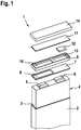
- Figure 1 shows a schematic and perspective exploded view of an embodiment of a secondary cell 1 according to the present invention for a traction battery (not shown) of a vehicle (not shown).
- the secondary cell 1 comprises a prismatic casing 2 having an aperture 3 at one side and being at least partly electrically conductive.
- the casing 2 is ashlar-shaped and may be manufactured by deep drawing.
- the secondary cell 1 comprises an electrochemical cell 4 contained within the casing 2 and comprising an anode current collector 5 and a cathode current collector 6. Both current collectors 5 and 6 are arranged on one side, i. e. the upper side in Figure 1 , of the electrochemical cell 4 accessible through the aperture 3 of the casing 2.
- the secondary cell 1 comprises an electrically conductive connecting element 7 electrically connecting the cathode current collector 6 with the casing 2.
- the cathode current collector 6 is welded to the connecting element 7.
- the connecting element 7 is welded to the casing 2.
- the connecting element 7 has a through hole 8 through which the anode current collector 5 is guided without contacting the connecting element 7.
- the secondary cell 1 comprises an electrically non-conductive insulating element 9 arranged on a side of the connecting element 7 facing away from the electrochemical cell 4.
- the insulating element 9 comprises a through hole 10 aligned with the through hole 8 of the connecting element 7.
- the connecting element 7 is formed as an aluminum plate extending along the side of the electrochemical cell 4 facing the insulating element 9 and has at least one through hole through which the other current collector is guided without contacting the connecting element.
- the secondary cell 1 comprises an electrically conductive member 11 electrically connected with the anode current collector 5 and arranged on a side of the insulating element 9 facing away from the electrochemical cell 4.
- the anode current collector 5 is welded to the electrically conductive member 11.
- the electrically conductive member 11 is formed as a copper plate extending along a side of the insulating element 9 facing away from the connecting element 7.
- the insulating element 9 extends along a side of the connecting element 7 facing the electrically conductive member 11.
- the connecting element 7 and the electrically conductive member 11 may be adhesively bonded to the insulating element 9.
- the insulating element 9 may comprise at least one clamping element (not shown) for clamping the electrically conductive member 11 to the insulating element 9.
- the secondary cell 1 comprises a fast discharge device 12 for discharging the electrochemical cell 4 when the electrochemical cell 4 is in an abnormal state and being electrically connected with the connecting element 7 and the electrically conductive member 11.
- the fast discharge device 12 is arranged in a hermetically sealed cavity (shown in Figure 2 ) defined by the connecting element 7, the electrically conductive member 11 and an opening 13 of the insulating element 9.
- the fast discharge device 12 may comprise: at least one first electrically conductive layer (not shown) electrically connectable to the anode current collector 5; at least one second electrically conductive layer (not shown) electrically connectable to the cathode current collector 6; at least one separator layer (not shown) being arranged between the first electrically conductive layer and the second electrically conductive layer to electrically separate the electrically conductive layers from one another; at least one first solder layer (not shown) which is at least partly arranged between the first electrically conductive layer and the separator layer; at least one safety layer (not shown) which is at least partly arranged between the separator layer and the second electrically conductive layer; and at least one second solder layer (not shown) which is at least partly arranged between the second electrically conductive layer and the safety layer.
- the safety layer may be formed so that, when a temperature of the safety layer exceeds a predetermined threshold temperature, an exothermic reaction of the safety layer material is triggered.
- the separator layer changes its state of matter from solid to liquid or gas due to heat generated by the exothermic reaction.
- the secondary cell 1 comprises a cap 14 being at least partly electrically conductive and welded to the electrically conductive member 11.
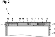
- Figure 2 shows a schematic cross section of a part of the secondary cell 1 shown in Figure 1 .
- Figure 2 shows the hermetically sealed cavity 15 defined by the connecting element 7, the electrically conductive member 11 and the opening 13 of the insulating element 9. Further, the different connections between components of the secondary cell 1 are shown in detail. Here, it is referred to the above description of Figure 1 to prevent repeated descriptions of components of the secondary cell 1 being the same as those shown in Figure 1 .
Priority Applications (2)
| Application Number | Priority Date | Filing Date | Title |
|---|---|---|---|
| EP17164746.4A EP3385997A1 (de) | 2017-04-04 | 2017-04-04 | Sekundärzelle und verfahren zur herstellung einer sekundärzelle |
| PCT/EP2018/052622 WO2018184751A1 (en) | 2017-04-04 | 2018-02-02 | Secondary cell for a traction battery and method for manufacturing a secondary cell |
Applications Claiming Priority (1)
| Application Number | Priority Date | Filing Date | Title |
|---|---|---|---|
| EP17164746.4A EP3385997A1 (de) | 2017-04-04 | 2017-04-04 | Sekundärzelle und verfahren zur herstellung einer sekundärzelle |
Publications (1)
| Publication Number | Publication Date |
|---|---|
| EP3385997A1 true EP3385997A1 (de) | 2018-10-10 |
Family
ID=58489235
Family Applications (1)
| Application Number | Title | Priority Date | Filing Date |
|---|---|---|---|
| EP17164746.4A Withdrawn EP3385997A1 (de) | 2017-04-04 | 2017-04-04 | Sekundärzelle und verfahren zur herstellung einer sekundärzelle |
Country Status (2)
| Country | Link |
|---|---|
| EP (1) | EP3385997A1 (de) |
| WO (1) | WO2018184751A1 (de) |
Citations (14)
| Publication number | Priority date | Publication date | Assignee | Title |
|---|---|---|---|---|
| US6229282B1 (en) * | 2000-03-22 | 2001-05-08 | Hughes Electronics Corporation | Low-voltage-drop, spring-activated bypass of failed battery cell |
| US6275005B1 (en) * | 2000-03-22 | 2001-08-14 | Hughes Electronics Corporation | Low-voltage-drop bypass of failed battery cell |
| US20050001710A1 (en) * | 2003-07-01 | 2005-01-06 | Takahiro Mukai | Fuse, battery pack using the fuse, and method of manufacturing the fuse |
| US20070188132A1 (en) * | 2005-10-21 | 2007-08-16 | Jung-Hwan Kim | No-welding type battery pack |
| US20080008928A1 (en) * | 2006-06-27 | 2008-01-10 | Boston-Power, Inc. | Integrated current-interrupt device for lithium-ion cells |
| EP2058875A2 (de) * | 2007-10-30 | 2009-05-13 | Samsung SDI Co., Ltd. | Sekundäre Batterie mit Schutzkreislaufmodul |
| US20100151280A1 (en) * | 2008-12-11 | 2010-06-17 | Seok Koh | Secondary battery |
| EP2254174A1 (de) * | 2009-05-15 | 2010-11-24 | Samsung SDI Co., Ltd. | Sekundärbatterie |
| US20120231301A1 (en) * | 2011-03-11 | 2012-09-13 | Samsung Sdi Co., Ltd. | Secondary Battery |
| US20130095364A1 (en) * | 2011-10-12 | 2013-04-18 | Jun-Sun Yong | Secondary battery |
| KR20130080331A (ko) | 2012-01-04 | 2013-07-12 | 주식회사 아이티엠반도체 | 배터리 보호회로의 패키지 모듈 |
| US20130344353A1 (en) | 2006-11-21 | 2013-12-26 | Samsung Sdi Co., Ltd. | Secondary battery with protective circuit module |
| US20140287279A1 (en) * | 2012-02-07 | 2014-09-25 | Lg Chem, Ltd. | Method for battery cell of novel structure |
| US20170069940A1 (en) * | 2014-03-06 | 2017-03-09 | Unicell Llc | Battery cells and arrangements |
-
2017
- 2017-04-04 EP EP17164746.4A patent/EP3385997A1/de not_active Withdrawn
-
2018
- 2018-02-02 WO PCT/EP2018/052622 patent/WO2018184751A1/en active Application Filing
Patent Citations (14)
| Publication number | Priority date | Publication date | Assignee | Title |
|---|---|---|---|---|
| US6275005B1 (en) * | 2000-03-22 | 2001-08-14 | Hughes Electronics Corporation | Low-voltage-drop bypass of failed battery cell |
| US6229282B1 (en) * | 2000-03-22 | 2001-05-08 | Hughes Electronics Corporation | Low-voltage-drop, spring-activated bypass of failed battery cell |
| US20050001710A1 (en) * | 2003-07-01 | 2005-01-06 | Takahiro Mukai | Fuse, battery pack using the fuse, and method of manufacturing the fuse |
| US20070188132A1 (en) * | 2005-10-21 | 2007-08-16 | Jung-Hwan Kim | No-welding type battery pack |
| US20080008928A1 (en) * | 2006-06-27 | 2008-01-10 | Boston-Power, Inc. | Integrated current-interrupt device for lithium-ion cells |
| US20130344353A1 (en) | 2006-11-21 | 2013-12-26 | Samsung Sdi Co., Ltd. | Secondary battery with protective circuit module |
| EP2058875A2 (de) * | 2007-10-30 | 2009-05-13 | Samsung SDI Co., Ltd. | Sekundäre Batterie mit Schutzkreislaufmodul |
| US20100151280A1 (en) * | 2008-12-11 | 2010-06-17 | Seok Koh | Secondary battery |
| EP2254174A1 (de) * | 2009-05-15 | 2010-11-24 | Samsung SDI Co., Ltd. | Sekundärbatterie |
| US20120231301A1 (en) * | 2011-03-11 | 2012-09-13 | Samsung Sdi Co., Ltd. | Secondary Battery |
| US20130095364A1 (en) * | 2011-10-12 | 2013-04-18 | Jun-Sun Yong | Secondary battery |
| KR20130080331A (ko) | 2012-01-04 | 2013-07-12 | 주식회사 아이티엠반도체 | 배터리 보호회로의 패키지 모듈 |
| US20140287279A1 (en) * | 2012-02-07 | 2014-09-25 | Lg Chem, Ltd. | Method for battery cell of novel structure |
| US20170069940A1 (en) * | 2014-03-06 | 2017-03-09 | Unicell Llc | Battery cells and arrangements |
Also Published As
| Publication number | Publication date |
|---|---|
| WO2018184751A1 (en) | 2018-10-11 |
Similar Documents
| Publication | Publication Date | Title |
|---|---|---|
| KR102259217B1 (ko) | 전지시스템 및 이를 포함하는 자동차 | |
| US9640790B2 (en) | Middle or large-sized battery module | |
| US9917336B2 (en) | Battery system | |
| US9887410B2 (en) | Flexible fusible link, systems, and methods | |
| EP2908377A1 (de) | Batteriegehäuse mit Kühlungssystem | |
| US8871377B2 (en) | Battery with a plurality of individual cells | |
| EP2744015A1 (de) | Batterieblock und batteriemodul damit | |
| CN111033805B (zh) | 电池模块 | |
| EP3696882A1 (de) | Batteriemodul mit sammelschiene und batteriepack | |
| EP3540817B1 (de) | Batteriepack | |
| CN107615514B (zh) | 电池模块和包括该电池模块的电池组 | |
| KR101985762B1 (ko) | 단자의 연결 구조가 개선된 이차 전지 및 이를 포함하는 전지 모듈 | |
| KR100913174B1 (ko) | 전지 모듈 | |
| US9059456B2 (en) | Rechargeable battery and battery module | |
| EP2827400B1 (de) | Plattenförmiges Batteriepack und Batteriepackgruppe aus mehreren plattenförmigen Batteriepacks | |
| EP3367458B1 (de) | Sekundäre zelle für eine traktionsbatterie und herstellungsverfahren einer sekundärzelle | |
| EP3385997A1 (de) | Sekundärzelle und verfahren zur herstellung einer sekundärzelle | |
| KR20130005117A (ko) | 배터리 셀 및 이를 포함하는 배터리 팩 | |
| KR20170040629A (ko) | 배터리 모듈 및 이를 포함하는 배터리 팩 | |
| CN110783643A (zh) | 电蓄能器、设备和/或车辆以及用于制造电蓄能器的方法 | |
| KR101749724B1 (ko) | 관통구가 형성된 pcb를 포함하는 전지팩 | |
| US20230231277A1 (en) | Battery pack | |
| JP7119831B2 (ja) | 蓄電装置 | |
| EP4191780A1 (de) | Batteriemodul mit mehreren parallelen batteriezellen | |
| KR20160109292A (ko) | 보호소자 및 이를 포함하는 이차 전지 |
Legal Events
| Date | Code | Title | Description |
|---|---|---|---|
| PUAI | Public reference made under article 153(3) epc to a published international application that has entered the european phase |
Free format text: ORIGINAL CODE: 0009012 |
|
| AK | Designated contracting states |
Kind code of ref document: A1 Designated state(s): AL AT BE BG CH CY CZ DE DK EE ES FI FR GB GR HR HU IE IS IT LI LT LU LV MC MK MT NL NO PL PT RO RS SE SI SK SM TR |
|
| AX | Request for extension of the european patent |
Extension state: BA ME |
|
| STAA | Information on the status of an ep patent application or granted ep patent |
Free format text: STATUS: THE APPLICATION IS DEEMED TO BE WITHDRAWN |
|
| 18D | Application deemed to be withdrawn |
Effective date: 20190411 |