EP3385974A1 - Residual current operated circuit breaker - Google Patents
Residual current operated circuit breaker Download PDFInfo
- Publication number
- EP3385974A1 EP3385974A1 EP18165872.5A EP18165872A EP3385974A1 EP 3385974 A1 EP3385974 A1 EP 3385974A1 EP 18165872 A EP18165872 A EP 18165872A EP 3385974 A1 EP3385974 A1 EP 3385974A1
- Authority
- EP
- European Patent Office
- Prior art keywords
- housing
- assembly
- circuit breaker
- accommodating chamber
- residual current
- Prior art date
- Legal status (The legal status is an assumption and is not a legal conclusion. Google has not performed a legal analysis and makes no representation as to the accuracy of the status listed.)
- Granted
Links
- 239000004020 conductor Substances 0.000 claims abstract description 47
- 238000009434 installation Methods 0.000 claims abstract description 36
- 230000007246 mechanism Effects 0.000 claims abstract description 24
- 230000003068 static effect Effects 0.000 claims description 11
- 230000009471 action Effects 0.000 claims description 6
- 238000000034 method Methods 0.000 abstract description 5
- 230000008569 process Effects 0.000 abstract description 2
- 238000010586 diagram Methods 0.000 description 5
- 230000001965 increasing effect Effects 0.000 description 3
- 238000001514 detection method Methods 0.000 description 2
- 230000002708 enhancing effect Effects 0.000 description 2
- 238000004519 manufacturing process Methods 0.000 description 2
- 230000000694 effects Effects 0.000 description 1
- 230000005611 electricity Effects 0.000 description 1
- 230000006872 improvement Effects 0.000 description 1
- 238000006467 substitution reaction Methods 0.000 description 1
Images


Classifications
-
- H—ELECTRICITY
- H01—ELECTRIC ELEMENTS
- H01H—ELECTRIC SWITCHES; RELAYS; SELECTORS; EMERGENCY PROTECTIVE DEVICES
- H01H83/00—Protective switches, e.g. circuit-breaking switches, or protective relays operated by abnormal electrical conditions otherwise than solely by excess current
- H01H83/20—Protective switches, e.g. circuit-breaking switches, or protective relays operated by abnormal electrical conditions otherwise than solely by excess current operated by excess current as well as by some other abnormal electrical condition
- H01H83/22—Protective switches, e.g. circuit-breaking switches, or protective relays operated by abnormal electrical conditions otherwise than solely by excess current operated by excess current as well as by some other abnormal electrical condition the other condition being imbalance of two or more currents or voltages
- H01H83/226—Protective switches, e.g. circuit-breaking switches, or protective relays operated by abnormal electrical conditions otherwise than solely by excess current operated by excess current as well as by some other abnormal electrical condition the other condition being imbalance of two or more currents or voltages with differential transformer
-
- H—ELECTRICITY
- H01—ELECTRIC ELEMENTS
- H01H—ELECTRIC SWITCHES; RELAYS; SELECTORS; EMERGENCY PROTECTIVE DEVICES
- H01H71/00—Details of the protective switches or relays covered by groups H01H73/00 - H01H83/00
- H01H71/02—Housings; Casings; Bases; Mountings
- H01H71/0207—Mounting or assembling the different parts of the circuit breaker
-
- H—ELECTRICITY
- H01—ELECTRIC ELEMENTS
- H01H—ELECTRIC SWITCHES; RELAYS; SELECTORS; EMERGENCY PROTECTIVE DEVICES
- H01H71/00—Details of the protective switches or relays covered by groups H01H73/00 - H01H83/00
- H01H71/08—Terminals; Connections
-
- H—ELECTRICITY
- H01—ELECTRIC ELEMENTS
- H01H—ELECTRIC SWITCHES; RELAYS; SELECTORS; EMERGENCY PROTECTIVE DEVICES
- H01H71/00—Details of the protective switches or relays covered by groups H01H73/00 - H01H83/00
- H01H71/002—Details of the protective switches or relays covered by groups H01H73/00 - H01H83/00 with provision for switching the neutral conductor
-
- H—ELECTRICITY
- H01—ELECTRIC ELEMENTS
- H01H—ELECTRIC SWITCHES; RELAYS; SELECTORS; EMERGENCY PROTECTIVE DEVICES
- H01H71/00—Details of the protective switches or relays covered by groups H01H73/00 - H01H83/00
- H01H71/02—Housings; Casings; Bases; Mountings
- H01H71/0207—Mounting or assembling the different parts of the circuit breaker
- H01H71/0221—Majority of parts mounted on central frame or wall
-
- H—ELECTRICITY
- H01—ELECTRIC ELEMENTS
- H01H—ELECTRIC SWITCHES; RELAYS; SELECTORS; EMERGENCY PROTECTIVE DEVICES
- H01H71/00—Details of the protective switches or relays covered by groups H01H73/00 - H01H83/00
- H01H71/10—Operating or release mechanisms
- H01H71/12—Automatic release mechanisms with or without manual release
- H01H71/40—Combined electrothermal and electromagnetic mechanisms
-
- H—ELECTRICITY
- H01—ELECTRIC ELEMENTS
- H01H—ELECTRIC SWITCHES; RELAYS; SELECTORS; EMERGENCY PROTECTIVE DEVICES
- H01H71/00—Details of the protective switches or relays covered by groups H01H73/00 - H01H83/00
- H01H71/10—Operating or release mechanisms
- H01H71/50—Manual reset mechanisms which may be also used for manual release
- H01H71/52—Manual reset mechanisms which may be also used for manual release actuated by lever
- H01H71/526—Manual reset mechanisms which may be also used for manual release actuated by lever the lever forming a toggle linkage with a second lever, the free end of which is directly and releasably engageable with a contact structure
Definitions
- the present invention relates to the field of low-voltage electricity, in particular to a residual current operated circuit breaker.
- RCBOs of the first type have the same width as a compact product, but because the leakage detection and N pole connection flexible conductors are located on the left side of the product, the product length is greater, so a special distribution box is still needed for installation. Moreover, since the N pole connection flexible conductor lacks the basic protection function of the RCBO, the reliability of the product is poor.
- RCBOs of the second type have the same dimensions as a compact product, but lack an N pole connection flexible conductor, so the product installation cost is higher, and the convenience of wiring by a user has room for improvement.
- the object of the present invention is to provide a residual current operated circuit breaker; a product thereof has a better protection function, a housing has a more compact structural layout, and a process of product installation and wiring is more convenient and reliable.
- the present invention provides a residual current operated circuit breaker, comprising: a housing, comprising a first housing, a second housing and an installation housing located therebetween, with a first accommodating chamber being formed between the first housing and the installation housing, and a second accommodating chamber being formed between the second housing and the installation housing; an electromagnetic trip apparatus and an arc extinguishing apparatus, disposed in the first accommodating chamber; a first operating mechanism, used for working in cooperation with the electromagnetic trip apparatus and being located on one side of the first accommodating chamber; a leakage trip apparatus, disposed in the second accommodating chamber; a second operating mechanism, used for working in cooperation with the leakage trip apparatus and being located on one side of the second accommodating chamber, with actions of the first operating mechanism and the second operating mechanism being capable of realizing the opening and closing of a current loop; a first terminal assembly, which may be used for an L pole incoming line, with an installation gap being provided on one side of the installation housing, the first terminal assembly being capable of running through the installation gap and being clamped in a space formed by the first housing and
- the second terminal assembly is located on one side, close to the electromagnetic trip apparatus, in the first accommodating chamber.
- an incoming line end of the third terminal assembly and an outgoing line end of the flexible conductor assembly are located on the same side of the housing.
- This design facilitates product installation and wiring, and the structural design of the housing interior is more compact, so the user has no need to use a special distribution box for installation; this helps to increase the user space utilization rate.
- the first operating mechanism comprises a first contact assembly and a first actuating assembly
- the second operating mechanism comprises a second contact assembly and a second actuating assembly
- linked movement of the first actuating assembly and second actuating assembly may be realized by means of a drive element and an operating handle.
- the flexible conductor assembly comprises: a connecting plate; a first connecting conductor, one end thereof being connected to a static contact in the second contact assembly, and another end thereof being connected to the connecting plate; a second connecting conductor, one end thereof being connected to the connecting plate, and another end thereof being a free connection end and extending to the outside of the housing, to save more space inside the housing; since one side of the first connecting conductor is connected to N pole moving and static contacts, an N pole connecting conductor contact opening/closing function can be realized.
- the connecting plate is a bent structure, and is provided with a trough-shaped first bent part, with an end of the first connecting conductor being accommodated in the first bent part; and a plate-like second bent part, with an end of the second connecting conductor being crimped to the second bent part, to help enhance the reliability of structural connection.
- a wiring capacity of the first terminal assembly is larger than a wiring capacity of the third terminal assembly; this can effectively enhance the electrical safety and reliability of the L pole wiring.
- the first terminal assembly has a current carrying range of 6 A - 32 A, and the first terminal assembly may be connected to a common bus bar, to meet the needs of large current input at the L pole, enhancing product applicability.
- the direction of an N pole current loop of the residual current operated circuit breaker is, in sequence, the third terminal assembly, an N pole moving contact, an N pole static contact, the first connecting conductor, the connecting plate and the second connecting conductor.
- thermal protection assembly being close to the arc extinguishing apparatus and located in the first accommodating chamber, for the purpose of realizing thermal protection of the circuit breaker.
- top, bottom, front, “rear”, “left” and “right” etc. are merely used to indicate a positional relationship between relevant parts, not to define their absolute positions.
- first and second are merely used to differentiate between parts, not to indicate their order or degree of importance, etc.
- the residual current operated circuit breaker 100 comprises a housing 10.
- the housing 10 comprises a first housing 11, a second housing 12 and an installation housing 13.
- the installation housing 13 is located between the first housing 11 and the second housing 12.
- a first accommodating chamber is formed between the first housing 11 and the installation housing 13;
- a second accommodating chamber is formed between the second housing 12 and the installation housing 13.
- the residual current operated circuit breaker 100 has a first current loop and a second current loop, wherein the first current loop is located in the first accommodating chamber, and the second current loop is located in the second accommodating chamber.
- the residual current operated circuit breaker 100 further comprises an electromagnetic trip apparatus 20, an arc extinguishing apparatus 30, a first operating mechanism 21, a leakage trip apparatus 40 and a second operating mechanism 42.
- the electromagnetic trip apparatus 20 and the arc extinguishing apparatus 30 are disposed in the first accommodating chamber.
- the first operating mechanism 21 is used for working in cooperation with the electromagnetic trip apparatus 20 and is located on one side of the first accommodating chamber; the action of the first operating mechanism 21 can realize opening and closing of the first current loop, for the purpose of realizing overcurrent protection of the residual current operated circuit breaker 100; the arc extinguishing apparatus 30 facilitates rapid extinguishing of an arc.
- the leakage trip apparatus 40 is disposed in the second accommodating chamber; the second operating mechanism 42 is used for working in cooperation with the leakage trip apparatus 40 and is located on one side of the second accommodating chamber; the action of the second operating mechanism 42 can realize opening and closing of the second current loop, for the purpose of realizing leakage protection of the residual current operated circuit breaker 100.
- the residual current operated circuit breaker 100 of the present invention also comprises a thermal protection assembly 31 formed of a bimetallic strip, which is close to the arc extinguishing apparatus 30 and located in the first accommodating chamber, and a circuit board assembly 80 for detection and control signal output, disposed in the second accommodating chamber.
- the residual current operated circuit breaker of the present invention also comprises a first terminal assembly 71 which may be used for an L pole incoming line, a second terminal assembly 72 which may be used for an L pole outgoing line, and a third terminal assembly 51 which may be used for an N pole incoming line.
- the first terminal assembly 71 of the present invention is of large size; in order to satisfy reliability of installation of the first terminal assembly 71 without increasing the size of the housing, preferably, an installation gap is provided on one side of the installation housing 13, and the first terminal assembly 71 can run through the installation gap and be clamped in the space formed by the first housing 11 and the second housing 12.
- the second terminal assembly 72 is accommodated in the first accommodating chamber, and the third terminal assembly 51 is accommodated in the second accommodating chamber.
- the second terminal assembly 72 is located on one side, close to the electromagnetic trip apparatus, in the first accommodating chamber.
- a wiring capacity of the first terminal assembly 71 is larger than a wiring capacity of the third terminal assembly 72. Since the first terminal assembly 71 of the present invention replaces a small terminal assembly used in the prior art, the use of a large terminal assembly with a larger wiring capacity can effectively enhance the electrical safety and reliability of L pole wiring. According to a preferred embodiment of the present invention, the first terminal assembly 71 has a current carrying range of 6 A - 32 A.
- the first terminal assembly 71 is optionally connected to a common bus bar; an L pole incoming line end may be connected to a conductor of larger cross section, to meet the needs of large current input at the L pole, enhancing product applicability, and increasing product competitiveness more effectively.
- a slider 83 is also disposed on one side of the housing 10 of the present invention, close to the first terminal assembly 71; the slider 83 can avoid the need for a user's finger to come into contact with electrified components, in order to effectively protect the user's personal safety, and also facilitates the task of removably connecting the circuit breaker to a corresponding rail in a flexible manner.
- the residual current operated circuit breaker of the present invention differs from the prior art in that an N pole outgoing line is realized by means of a flexible conductor assembly 60, and the flexible conductor assembly 60 has a contact opening/closing function, thereby being able to enhance the electrical safety and reliability of an N pole current loop.
- the flexible conductor assembly 60 is accommodated in the second accommodating chamber.
- an incoming line end of the third terminal assembly 51 and an outgoing line end of the flexible conductor assembly 60 are located on the same side of the housing 10; this design facilitates product installation and wiring, and increases user space utilization rate.
- the first operating mechanism 21 comprises: a first contact assembly 22 and a first actuating assembly 23.
- the second operating mechanism 42 comprises a second contact assembly 43 and a second actuating assembly 44. More specifically, the action of the first contact assembly 22 and the first actuating assembly 23 can realize the opening and closing of an L pole current loop. The action of the second contact assembly 43 and the second actuating assembly 44 can realize the opening and closing of the N pole current loop. Linked movement of the first actuating assembly 23 and second actuating assembly 44 may be realized by means of a drive element 81 and an operating handle 82.
- the flexible conductor assembly 60 comprises a connecting plate 63, a first connecting conductor 61 and a second connecting conductor 62.
- first connecting conductor 61 is connected to a static contact 431 in the second contact assembly 43; another end of the first connecting conductor 61 is connected to the connecting plate 63.
- One end of the second connecting conductor 62 is connected to the connecting plate 63; another end of the second connecting conductor 62 is a free connection end and extends to the outside of the housing 10.
- the direction of the L pole current loop of the present invention is, in sequence, the first terminal assembly 71, an L pole moving contact 222, an L pole static contact 221 and the second terminal assembly 72.
- the direction of the N pole current loop is, in sequence, the third terminal assembly 51, an N pole moving contact 432, the N pole static contact 431, the first connecting conductor 61, the connecting plate 63 and the second connecting conductor 62.
- the connecting plate 63 may have a bent structure, and can be stably engaged in an installation groove formed jointly by multiple limiting ribs on an inner surface of the housing.
- the connecting plate 63 is also provided with a first bent part 631 and a second bent part 632.
- the first bent part 631 may be trough-shaped, and an end of the first connecting conductor 61 can be accommodated in the trough-shaped first bent part 631.
- the second bent part 632 may be plate-like, and an end of the second connecting conductor 62 is crimped to the plate-like second bent part 632. It is worth pointing out that the shape and structure of the connecting plate 63 are not unique; those skilled in the art could make various changes and substitutions according to actual needs when the same functions can be realized, without departing from the scope of protection of the present invention.
- the residual current operated circuit breaker according to the present invention can provide the user with a method of wiring that is more convenient and reliable, and on condition that it is ensured that the product has perfect safety protection, still has an optimal housing structure, effectively saving installation space for the user, and at the same time, since a flexible conductor is used to replace a wiring terminal, the processing technology of the product can be simplified, and the product cost is reduced.
Landscapes
- Engineering & Computer Science (AREA)
- Power Engineering (AREA)
- Breakers (AREA)
Abstract
Description
- This patent application claims the priority of Chinese patent application
201710221946.4 filed 6. Apr. 2017 - The present invention relates to the field of low-voltage electricity, in particular to a residual current operated circuit breaker.
- As is well known, residual current circuit breakers not only have the control, overload and short circuit protection functions of conventional miniature circuit breakers (MCB), but also have a leakage protection function, so can actively protect the safety of life and property, being able to rapidly cut off a faulty power supply within a short time, to protect the safety of people and electrical appliances.
- Existing RCBOs are generally divided into the following two forms of implementation, depending on their own structural layout. RCBOs of the first type have the same width as a compact product, but because the leakage detection and N pole connection flexible conductors are located on the left side of the product, the product length is greater, so a special distribution box is still needed for installation. Moreover, since the N pole connection flexible conductor lacks the basic protection function of the RCBO, the reliability of the product is poor. RCBOs of the second type have the same dimensions as a compact product, but lack an N pole connection flexible conductor, so the product installation cost is higher, and the convenience of wiring by a user has room for improvement.
- To resolve the abovementioned shortcomings, there is an urgent need for those skilled in the art to research and develop a new type of residual current operated circuit breaker.
- The object of the present invention is to provide a residual current operated circuit breaker; a product thereof has a better protection function, a housing has a more compact structural layout, and a process of product installation and wiring is more convenient and reliable.
- The present invention provides a residual current operated circuit breaker, comprising: a housing, comprising a first housing, a second housing and an installation housing located therebetween, with a first accommodating chamber being formed between the first housing and the installation housing, and a second accommodating chamber being formed between the second housing and the installation housing; an electromagnetic trip apparatus and an arc extinguishing apparatus, disposed in the first accommodating chamber; a first operating mechanism, used for working in cooperation with the electromagnetic trip apparatus and being located on one side of the first accommodating chamber; a leakage trip apparatus, disposed in the second accommodating chamber; a second operating mechanism, used for working in cooperation with the leakage trip apparatus and being located on one side of the second accommodating chamber, with actions of the first operating mechanism and the second operating mechanism being capable of realizing the opening and closing of a current loop; a first terminal assembly, which may be used for an L pole incoming line, with an installation gap being provided on one side of the installation housing, the first terminal assembly being capable of running through the installation gap and being clamped in a space formed by the first housing and the second housing; a second terminal assembly, which may be used for an L pole outgoing line, being accommodated in the first accommodating chamber; a third terminal assembly, which may be used for an N pole incoming line, being accommodated in the second accommodating chamber; a flexible conductor assembly having a contact opening/closing function, which may be used for an N pole outgoing line, being accommodated in the second accommodating chamber. This design can provide the user with a method of wiring that is more convenient and reliable, and on condition that it is ensured that the product has perfect safety protection, still has an optimal housing structure.
- According to one aspect of the present invention, the second terminal assembly is located on one side, close to the electromagnetic trip apparatus, in the first accommodating chamber.
- According to another aspect of the present invention, an incoming line end of the third terminal assembly and an outgoing line end of the flexible conductor assembly are located on the same side of the housing. This design facilitates product installation and wiring, and the structural design of the housing interior is more compact, so the user has no need to use a special distribution box for installation; this helps to increase the user space utilization rate.
- According to another aspect of the present invention, the first operating mechanism comprises a first contact assembly and a first actuating assembly, the second operating mechanism comprises a second contact assembly and a second actuating assembly, and linked movement of the first actuating assembly and second actuating assembly may be realized by means of a drive element and an operating handle.
- According to another aspect of the present invention, the flexible conductor assembly comprises: a connecting plate; a first connecting conductor, one end thereof being connected to a static contact in the second contact assembly, and another end thereof being connected to the connecting plate; a second connecting conductor, one end thereof being connected to the connecting plate, and another end thereof being a free connection end and extending to the outside of the housing, to save more space inside the housing; since one side of the first connecting conductor is connected to N pole moving and static contacts, an N pole connecting conductor contact opening/closing function can be realized.
- According to another aspect of the present invention, the connecting plate is a bent structure, and is provided with a trough-shaped first bent part, with an end of the first connecting conductor being accommodated in the first bent part; and a plate-like second bent part, with an end of the second connecting conductor being crimped to the second bent part, to help enhance the reliability of structural connection.
- According to another aspect of the present invention, a wiring capacity of the first terminal assembly is larger than a wiring capacity of the third terminal assembly; this can effectively enhance the electrical safety and reliability of the L pole wiring.
- According to another aspect of the present invention, the first terminal assembly has a current carrying range of 6 A - 32 A, and the first terminal assembly may be connected to a common bus bar, to meet the needs of large current input at the L pole, enhancing product applicability.
- According to another aspect of the present invention, the direction of an N pole current loop of the residual current operated circuit breaker is, in sequence, the third terminal assembly, an N pole moving contact, an N pole static contact, the first connecting conductor, the connecting plate and the second connecting conductor.
- According to another aspect of the present invention, also included is a thermal protection assembly, being close to the arc extinguishing apparatus and located in the first accommodating chamber, for the purpose of realizing thermal protection of the circuit breaker.
- The present invention is explained in detail below in conjunction with the accompanying drawings and particular embodiments. In the drawings:
-
Fig. 1 is a schematic diagram of the product structure of a residual current operated circuit breaker according to an embodiment of the present invention; -
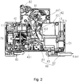
fig. 2 is a schematic diagram of an N pole structure of the residual current operated circuit breaker shown infig. 1 ; -
fig. 3 is a schematic diagram of an L pole structure of the residual current operated circuit breaker shown infig. 1 ; -
fig. 4 is an exploded schematic diagram of part of the structure offig. 2 ; and -
fig. 5 is an exploded schematic diagram of part of the structure offig. 3 . - To enable clearer understanding of the technical features, objectives and effects of the invention, particular embodiments of the present invention are now explained with reference to the accompanying drawings, in which identical labels indicate identical parts. In the drawings representing the embodiments, if the final two digits are the same, this indicates components having the same structure, or having similar structures but the same function.
- To make the drawings appear uncluttered, only those parts relevant to the present invention are shown schematically in the drawings; they do not represent the actual structure thereof as a product. Furthermore, to make the drawings appear uncluttered for ease of understanding, in the case of components having the same structure or function in certain drawings, only one of these is drawn schematically, or only one is marked.
- As used herein, "top", "bottom", "front", "rear", "left" and "right" etc. are merely used to indicate a positional relationship between relevant parts, not to define their absolute positions.
- As used herein, "first" and "second" etc. are merely used to differentiate between parts, not to indicate their order or degree of importance, etc.
- As used herein, "parallel" and "perpendicular" etc. are not strict limitations in the mathematical and/or geometric sense, but include errors which can be understood by those skilled in the art and are permitted in manufacture or use, etc.
- Referring to
fig. 1 , this shows a residual current operated circuit breaker according to an embodiment of the present invention; the residual current operatedcircuit breaker 100 comprises ahousing 10. Thehousing 10 comprises afirst housing 11, asecond housing 12 and aninstallation housing 13. Theinstallation housing 13 is located between thefirst housing 11 and thesecond housing 12. A first accommodating chamber is formed between thefirst housing 11 and theinstallation housing 13; a second accommodating chamber is formed between thesecond housing 12 and theinstallation housing 13. The residual current operatedcircuit breaker 100 has a first current loop and a second current loop, wherein the first current loop is located in the first accommodating chamber, and the second current loop is located in the second accommodating chamber. - Referring to
figs. 2 and3 , the residual current operatedcircuit breaker 100 further comprises anelectromagnetic trip apparatus 20, anarc extinguishing apparatus 30, afirst operating mechanism 21, aleakage trip apparatus 40 and asecond operating mechanism 42. Specifically, theelectromagnetic trip apparatus 20 and the arcextinguishing apparatus 30 are disposed in the first accommodating chamber. Thefirst operating mechanism 21 is used for working in cooperation with theelectromagnetic trip apparatus 20 and is located on one side of the first accommodating chamber; the action of thefirst operating mechanism 21 can realize opening and closing of the first current loop, for the purpose of realizing overcurrent protection of the residual current operatedcircuit breaker 100; thearc extinguishing apparatus 30 facilitates rapid extinguishing of an arc. Theleakage trip apparatus 40 is disposed in the second accommodating chamber; thesecond operating mechanism 42 is used for working in cooperation with theleakage trip apparatus 40 and is located on one side of the second accommodating chamber; the action of thesecond operating mechanism 42 can realize opening and closing of the second current loop, for the purpose of realizing leakage protection of the residual current operatedcircuit breaker 100. In order to realize a thermal protection function, the residual current operatedcircuit breaker 100 of the present invention also comprises athermal protection assembly 31 formed of a bimetallic strip, which is close to thearc extinguishing apparatus 30 and located in the first accommodating chamber, and acircuit board assembly 80 for detection and control signal output, disposed in the second accommodating chamber. - Referring to
figs. 4 and5 , in order to satisfy wiring functions of an L pole and an N pole, the residual current operated circuit breaker of the present invention also comprises afirst terminal assembly 71 which may be used for an L pole incoming line, asecond terminal assembly 72 which may be used for an L pole outgoing line, and athird terminal assembly 51 which may be used for an N pole incoming line. It is worth pointing out that compared with a terminal assembly in the prior art, thefirst terminal assembly 71 of the present invention is of large size; in order to satisfy reliability of installation of thefirst terminal assembly 71 without increasing the size of the housing, preferably, an installation gap is provided on one side of theinstallation housing 13, and thefirst terminal assembly 71 can run through the installation gap and be clamped in the space formed by thefirst housing 11 and thesecond housing 12. Thesecond terminal assembly 72 is accommodated in the first accommodating chamber, and thethird terminal assembly 51 is accommodated in the second accommodating chamber. Preferably, thesecond terminal assembly 72 is located on one side, close to the electromagnetic trip apparatus, in the first accommodating chamber. - In particular, a wiring capacity of the
first terminal assembly 71 is larger than a wiring capacity of thethird terminal assembly 72. Since thefirst terminal assembly 71 of the present invention replaces a small terminal assembly used in the prior art, the use of a large terminal assembly with a larger wiring capacity can effectively enhance the electrical safety and reliability of L pole wiring. According to a preferred embodiment of the present invention, thefirst terminal assembly 71 has a current carrying range of 6 A - 32 A. Thefirst terminal assembly 71 is optionally connected to a common bus bar; an L pole incoming line end may be connected to a conductor of larger cross section, to meet the needs of large current input at the L pole, enhancing product applicability, and increasing product competitiveness more effectively. Optionally, aslider 83 is also disposed on one side of thehousing 10 of the present invention, close to thefirst terminal assembly 71; theslider 83 can avoid the need for a user's finger to come into contact with electrified components, in order to effectively protect the user's personal safety, and also facilitates the task of removably connecting the circuit breaker to a corresponding rail in a flexible manner. - In order to enable the user to manage and use the circuit breaker more easily, the residual current operated circuit breaker of the present invention differs from the prior art in that an N pole outgoing line is realized by means of a
flexible conductor assembly 60, and theflexible conductor assembly 60 has a contact opening/closing function, thereby being able to enhance the electrical safety and reliability of an N pole current loop. Referring tofigs. 2 and4 , theflexible conductor assembly 60 is accommodated in the second accommodating chamber. According to a preferred embodiment of the present invention, an incoming line end of thethird terminal assembly 51 and an outgoing line end of theflexible conductor assembly 60 are located on the same side of thehousing 10; this design facilitates product installation and wiring, and increases user space utilization rate. Since the structural design of the housing interior is more compact, the overall length of the circuit breaker product is unchanged, so the user has no need to use a special distribution box for installation, and the convenience of product installation is increased effectively. Moreover, since a flexible conductor is used to replace a wiring terminal, processing technology can be simplified, effectively reducing the production cost of the product. - Referring to
figs. 2 and3 , furthermore, thefirst operating mechanism 21 comprises: afirst contact assembly 22 and afirst actuating assembly 23. Thesecond operating mechanism 42 comprises asecond contact assembly 43 and asecond actuating assembly 44. More specifically, the action of thefirst contact assembly 22 and thefirst actuating assembly 23 can realize the opening and closing of an L pole current loop. The action of thesecond contact assembly 43 and thesecond actuating assembly 44 can realize the opening and closing of the N pole current loop. Linked movement of thefirst actuating assembly 23 andsecond actuating assembly 44 may be realized by means of adrive element 81 and anoperating handle 82. - As shown in
fig. 4 , according to a preferred embodiment of the present invention, theflexible conductor assembly 60 comprises a connectingplate 63, a first connectingconductor 61 and a second connectingconductor 62. Specifically, one end of the first connectingconductor 61 is connected to astatic contact 431 in thesecond contact assembly 43; another end of the first connectingconductor 61 is connected to the connectingplate 63. One end of the second connectingconductor 62 is connected to the connectingplate 63; another end of the second connectingconductor 62 is a free connection end and extends to the outside of thehousing 10. Referring tofigs. 2 and3 , the direction of the L pole current loop of the present invention is, in sequence, the firstterminal assembly 71, an Lpole moving contact 222, an L polestatic contact 221 and the secondterminal assembly 72. The direction of the N pole current loop is, in sequence, the thirdterminal assembly 51, an Npole moving contact 432, the N polestatic contact 431, the first connectingconductor 61, the connectingplate 63 and the second connectingconductor 62. With such a design, since one side of the first connectingconductor 61 is connected to the N pole moving andstatic contacts flexible conductor assembly 60 has a contact opening/closing function. Compared with the prior art, the protection function and reliability of the N pole of the circuit breaker of the present invention are therefore vastly improved. - Referring to
fig. 4 , preferably, in a schematic embodiment, in order to save space inside the housing and enhance installation reliability, the connectingplate 63 may have a bent structure, and can be stably engaged in an installation groove formed jointly by multiple limiting ribs on an inner surface of the housing. Preferably, the connectingplate 63 is also provided with a firstbent part 631 and a secondbent part 632. To enhance the stability of electrical connection, the firstbent part 631 may be trough-shaped, and an end of the first connectingconductor 61 can be accommodated in the trough-shaped firstbent part 631. The secondbent part 632 may be plate-like, and an end of the second connectingconductor 62 is crimped to the plate-like secondbent part 632. It is worth pointing out that the shape and structure of the connectingplate 63 are not unique; those skilled in the art could make various changes and substitutions according to actual needs when the same functions can be realized, without departing from the scope of protection of the present invention. - The residual current operated circuit breaker according to the present invention can provide the user with a method of wiring that is more convenient and reliable, and on condition that it is ensured that the product has perfect safety protection, still has an optimal housing structure, effectively saving installation space for the user, and at the same time, since a flexible conductor is used to replace a wiring terminal, the processing technology of the product can be simplified, and the product cost is reduced.
- As used herein, "schematic" means "serving as an instance, example or illustration". No drawing or embodiment described herein as "schematic" should be interpreted as a more preferred or more advantageous technical solution.
- It should be understood that although the description herein is based on various embodiments, it is by no means the case that each embodiment contains just one independent technical solution. Such a method of presentation is adopted herein purely for the sake of clarity. Those skilled in the art should consider the description in its entirety. The technical solutions in the various embodiments could also be suitably combined to form other embodiments capable of being understood by those skilled in the art.
- The series of detailed explanations set out above are merely particular explanations of feasible embodiments of the present utility model, which are not intended to limit the scope of protection thereof. All equivalent embodiments or changes made without departing from the artistic spirit of the present utility model shall be included in the scope of protection thereof.
| residual current operated | |
| | |
| | |
| | |
| | |
| | |
| | first connecting |
| | second connecting conductor 62 |
| L pole | connecting plate 63 |
| L | first bent part 631 |
| N pole | second bent part 632 |
| N | |
| | |
| arc | |
| | |
| |
Claims (10)
- A residual current operated circuit breaker (100), comprising:a housing (10), comprising a first housing (11), a second housing (12) and an installation housing (13) located therebetween, with a first accommodating chamber being formed between the first housing (11) and the installation housing (13), and a second accommodating chamber being formed between the second housing (12) and the installation housing (13);an electromagnetic trip apparatus (20) and an arc extinguishing apparatus (30), disposed in the first accommodating chamber;a first operating mechanism (21), used for working in cooperation with the electromagnetic trip apparatus (20) and being located on one side of the first accommodating chamber;a leakage trip apparatus (40), disposed in the second accommodating chamber;a second operating mechanism (42), used for working in cooperation with the leakage trip apparatus (40) and being located on one side of the second accommodating chamber, with actions of the first operating mechanism (21) and the second operating mechanism (42) being capable of realizing the opening and closing of a current loop;a first terminal assembly (71), which may be used for an L pole incoming line, with an installation gap being provided on one side of the installation housing (13), the first terminal assembly (71) being capable of running through the installation gap and being clamped in a space formed by the first housing (11) and the second housing (12);a second terminal assembly (72), which may be used for an L pole outgoing line, being accommodated in the first accommodating chamber;a third terminal assembly (51), which may be used for an N pole incoming line, being accommodated in the second accommodating chamber;a flexible conductor assembly (60) having a contact opening/closing function, which may be used for an N pole outgoing line, being accommodated in the second accommodating chamber.
- The residual current operated circuit breaker as claimed in claim 1, wherein the second terminal assembly (72) is located on one side, close to the electromagnetic trip apparatus (20), in the first accommodating chamber.
- The residual current operated circuit breaker as claimed in claim 1, wherein an incoming line end of the third terminal assembly (51) and an outgoing line end of the flexible conductor assembly (60) are located on the same side of the housing (10).
- The residual current operated circuit breaker as claimed in claim 1, wherein the first operating mechanism (21) comprises a first contact assembly (22) and a first actuating assembly (23), the second operating mechanism (42) comprises a second contact assembly (43) and a second actuating assembly (44), and linked movement of the first actuating assembly (23) and second actuating assembly (44) may be realized by means of a drive element (81) and an operating handle (82).
- The residual current operated circuit breaker as claimed in claim 4, wherein the flexible conductor assembly (60) comprises:a connecting plate (63);a first connecting conductor (61), one end thereof being connected to a static contact (431) in the second contact assembly (43), and another end thereof being connected to the connecting plate (63);a second connecting conductor (62), one end thereof being connected to the connecting plate (63), and another end thereof being a free connection end and extending to the outside of the housing (10).
- The residual current operated circuit breaker as claimed in claim 5, wherein the connecting plate (63) is a bent structure, and is provided with
a trough-shaped first bent part (631), with an end of the first connecting conductor (61) being accommodated in the first bent part (631); and
a plate-like second bent part (632), with an end of the second connecting conductor (62) being crimped to the second bent part (632). - The residual current operated circuit breaker as claimed in claim 1, wherein a wiring capacity of the first terminal assembly (71) is larger than a wiring capacity of the third terminal assembly (72).
- The residual current operated circuit breaker as claimed in claim 1, wherein the first terminal assembly (71) has a current carrying range of 6 A - 32 A, and the first terminal assembly (71) may be connected to a common bus bar.
- The residual current operated circuit breaker as claimed in claim 1, wherein the direction of an N pole current loop of the residual current operated circuit breaker (100) is, in sequence, the third terminal assembly (51), an N pole moving contact (432), an N pole static contact (431), the first connecting conductor (61), the connecting plate (63) and the second connecting conductor (62).
- The residual current operated circuit breaker as claimed in claim 1, further comprising a thermal protection assembly (31), being close to the arc extinguishing apparatus (30) and located in the first accommodating chamber.
Applications Claiming Priority (1)
| Application Number | Priority Date | Filing Date | Title |
|---|---|---|---|
| CN201710221946.4A CN108695115B (en) | 2017-04-06 | 2017-04-06 | Residual current operated circuit breaker |
Publications (2)
| Publication Number | Publication Date |
|---|---|
| EP3385974A1 true EP3385974A1 (en) | 2018-10-10 |
| EP3385974B1 EP3385974B1 (en) | 2024-02-14 |
Family
ID=61906749
Family Applications (1)
| Application Number | Title | Priority Date | Filing Date |
|---|---|---|---|
| EP18165872.5A Active EP3385974B1 (en) | 2017-04-06 | 2018-04-05 | Residual current operated circuit breaker |
Country Status (2)
| Country | Link |
|---|---|
| EP (1) | EP3385974B1 (en) |
| CN (1) | CN108695115B (en) |
Cited By (1)
| Publication number | Priority date | Publication date | Assignee | Title |
|---|---|---|---|---|
| EP3726560A1 (en) * | 2019-04-17 | 2020-10-21 | Siemens Aktiengesellschaft | Compact protective switching device |
Families Citing this family (1)
| Publication number | Priority date | Publication date | Assignee | Title |
|---|---|---|---|---|
| CN111223727A (en) * | 2018-11-27 | 2020-06-02 | 俊郎电气有限公司 | C65 small-sized leakage ground fault protection circuit breaker |
Citations (3)
| Publication number | Priority date | Publication date | Assignee | Title |
|---|---|---|---|---|
| EP2242077A2 (en) * | 2009-04-18 | 2010-10-20 | General Electric Company | Space allocation within a circuit breaker |
| EP2506283A1 (en) * | 2011-03-30 | 2012-10-03 | General Electric Company | Compact residual current breaker with overcurrent protection |
| CN102760622A (en) * | 2012-07-23 | 2012-10-31 | 李文杰 | Un-lengthened 18mm-width multifunctional residual current circuit breaker |
Family Cites Families (4)
| Publication number | Priority date | Publication date | Assignee | Title |
|---|---|---|---|---|
| CN101728126A (en) * | 2008-10-13 | 2010-06-09 | 施耐德电器工业公司 | Electronic leakage protector |
| CN201725756U (en) * | 2010-06-30 | 2011-01-26 | 宏达电器集团有限公司 | Residual current circuit breaker |
| CN203690222U (en) * | 2013-09-18 | 2014-07-02 | 德力西电气有限公司 | Electronic electric leakage breaker capable of being connected through top part and down part |
| CN106158546B (en) * | 2015-03-26 | 2019-08-13 | 西门子公司 | Breaker |
-
2017
- 2017-04-06 CN CN201710221946.4A patent/CN108695115B/en active Active
-
2018
- 2018-04-05 EP EP18165872.5A patent/EP3385974B1/en active Active
Patent Citations (3)
| Publication number | Priority date | Publication date | Assignee | Title |
|---|---|---|---|---|
| EP2242077A2 (en) * | 2009-04-18 | 2010-10-20 | General Electric Company | Space allocation within a circuit breaker |
| EP2506283A1 (en) * | 2011-03-30 | 2012-10-03 | General Electric Company | Compact residual current breaker with overcurrent protection |
| CN102760622A (en) * | 2012-07-23 | 2012-10-31 | 李文杰 | Un-lengthened 18mm-width multifunctional residual current circuit breaker |
Cited By (1)
| Publication number | Priority date | Publication date | Assignee | Title |
|---|---|---|---|---|
| EP3726560A1 (en) * | 2019-04-17 | 2020-10-21 | Siemens Aktiengesellschaft | Compact protective switching device |
Also Published As
| Publication number | Publication date |
|---|---|
| CN108695115A (en) | 2018-10-23 |
| EP3385974B1 (en) | 2024-02-14 |
| CN108695115B (en) | 2020-05-26 |
Similar Documents
| Publication | Publication Date | Title |
|---|---|---|
| CN210956485U (en) | Disconnector, disconnector assembly and contactor | |
| JP6113867B2 (en) | Breaker | |
| CN210897140U (en) | Breaker and contactor | |
| EP3385974A1 (en) | Residual current operated circuit breaker | |
| CN107230586A (en) | A kind of miniature circuit breaker structure-improved | |
| US2922004A (en) | Electric circuit breaker | |
| CN204407262U (en) | A kind of circuit breaker shell body construction | |
| AU2022204661B2 (en) | Miniature circuit breaker | |
| CN204332851U (en) | A kind of circuit breaker shell body construction | |
| BRPI0910151A2 (en) | electric arc extinguishing cage and circuit breaker | |
| CN209895999U (en) | Leakage protection module | |
| CN204407263U (en) | A kind of circuit breaker shell body construction | |
| CN204464213U (en) | A kind of structure of contact terminal of direct current breaker of plastic casing | |
| CN205452090U (en) | Arc control device of double break point contact | |
| CN207651438U (en) | Breaker | |
| CN108682598B (en) | Vertical structure circuit breaker | |
| CN206003729U (en) | Static contact, arc extinguishing external member and chopper | |
| CN209571363U (en) | Safety-type thermal protector | |
| CN110571919A (en) | Dual-power switching distributor | |
| CN105810511A (en) | Circuit breaker housing body structure | |
| CN203325741U (en) | Mini breaker | |
| CN210006629U (en) | Dustproof instant-action type auxiliary switch | |
| CN112863953B (en) | Asynchronous double-break contact mechanism and residual current operated circuit breaker | |
| CN213459605U (en) | Small-sized circuit breaker | |
| CN213905955U (en) | Emergency lighting distribution box suitable for comprehensive pipe rack environment |
Legal Events
| Date | Code | Title | Description |
|---|---|---|---|
| PUAI | Public reference made under article 153(3) epc to a published international application that has entered the european phase |
Free format text: ORIGINAL CODE: 0009012 |
|
| STAA | Information on the status of an ep patent application or granted ep patent |
Free format text: STATUS: THE APPLICATION HAS BEEN PUBLISHED |
|
| AK | Designated contracting states |
Kind code of ref document: A1 Designated state(s): AL AT BE BG CH CY CZ DE DK EE ES FI FR GB GR HR HU IE IS IT LI LT LU LV MC MK MT NL NO PL PT RO RS SE SI SK SM TR |
|
| AX | Request for extension of the european patent |
Extension state: BA ME |
|
| STAA | Information on the status of an ep patent application or granted ep patent |
Free format text: STATUS: REQUEST FOR EXAMINATION WAS MADE |
|
| STAA | Information on the status of an ep patent application or granted ep patent |
Free format text: STATUS: REQUEST FOR EXAMINATION WAS MADE |
|
| 17P | Request for examination filed |
Effective date: 20190328 |
|
| RBV | Designated contracting states (corrected) |
Designated state(s): AL AT BE BG CH CY CZ DE DK EE ES FI FR GB GR HR HU IE IS IT LI LT LU LV MC MK MT NL NO PL PT RO RS SE SI SK SM TR |
|
| STAA | Information on the status of an ep patent application or granted ep patent |
Free format text: STATUS: EXAMINATION IS IN PROGRESS |
|
| 17Q | First examination report despatched |
Effective date: 20210520 |
|
| STAA | Information on the status of an ep patent application or granted ep patent |
Free format text: STATUS: EXAMINATION IS IN PROGRESS |
|
| RIC1 | Information provided on ipc code assigned before grant |
Ipc: H01H 71/02 20060101ALN20230731BHEP Ipc: H01H 71/40 20060101ALN20230731BHEP Ipc: H01H 71/08 20060101ALN20230731BHEP Ipc: H01H 83/22 20060101AFI20230731BHEP |
|
| RIC1 | Information provided on ipc code assigned before grant |
Ipc: H01H 71/02 20060101ALN20230817BHEP Ipc: H01H 71/40 20060101ALN20230817BHEP Ipc: H01H 71/08 20060101ALN20230817BHEP Ipc: H01H 83/22 20060101AFI20230817BHEP |
|
| GRAP | Despatch of communication of intention to grant a patent |
Free format text: ORIGINAL CODE: EPIDOSNIGR1 |
|
| STAA | Information on the status of an ep patent application or granted ep patent |
Free format text: STATUS: GRANT OF PATENT IS INTENDED |
|
| INTG | Intention to grant announced |
Effective date: 20230928 |
|
| GRAS | Grant fee paid |
Free format text: ORIGINAL CODE: EPIDOSNIGR3 |
|
| GRAA | (expected) grant |
Free format text: ORIGINAL CODE: 0009210 |
|
| STAA | Information on the status of an ep patent application or granted ep patent |
Free format text: STATUS: THE PATENT HAS BEEN GRANTED |
|
| AK | Designated contracting states |
Kind code of ref document: B1 Designated state(s): AL AT BE BG CH CY CZ DE DK EE ES FI FR GB GR HR HU IE IS IT LI LT LU LV MC MK MT NL NO PL PT RO RS SE SI SK SM TR |
|
| REG | Reference to a national code |
Ref country code: GB Ref legal event code: FG4D |
|
| REG | Reference to a national code |
Ref country code: CH Ref legal event code: EP |
|
| REG | Reference to a national code |
Ref country code: DE Ref legal event code: R096 Ref document number: 602018065129 Country of ref document: DE |
|
| REG | Reference to a national code |
Ref country code: IE Ref legal event code: FG4D |
|
| REG | Reference to a national code |
Ref country code: LT Ref legal event code: MG9D |
|
| REG | Reference to a national code |
Ref country code: NL Ref legal event code: MP Effective date: 20240214 |
|
| PG25 | Lapsed in a contracting state [announced via postgrant information from national office to epo] |
Ref country code: IS Free format text: LAPSE BECAUSE OF FAILURE TO SUBMIT A TRANSLATION OF THE DESCRIPTION OR TO PAY THE FEE WITHIN THE PRESCRIBED TIME-LIMIT Effective date: 20240614 |
|
| PG25 | Lapsed in a contracting state [announced via postgrant information from national office to epo] |
Ref country code: LT Free format text: LAPSE BECAUSE OF FAILURE TO SUBMIT A TRANSLATION OF THE DESCRIPTION OR TO PAY THE FEE WITHIN THE PRESCRIBED TIME-LIMIT Effective date: 20240214 |
|
| PGFP | Annual fee paid to national office [announced via postgrant information from national office to epo] |
Ref country code: DE Payment date: 20240619 Year of fee payment: 7 |
|
| PG25 | Lapsed in a contracting state [announced via postgrant information from national office to epo] |
Ref country code: GR Free format text: LAPSE BECAUSE OF FAILURE TO SUBMIT A TRANSLATION OF THE DESCRIPTION OR TO PAY THE FEE WITHIN THE PRESCRIBED TIME-LIMIT Effective date: 20240515 |
|
| REG | Reference to a national code |
Ref country code: AT Ref legal event code: MK05 Ref document number: 1657787 Country of ref document: AT Kind code of ref document: T Effective date: 20240214 |
|
| PG25 | Lapsed in a contracting state [announced via postgrant information from national office to epo] |
Ref country code: RS Free format text: LAPSE BECAUSE OF FAILURE TO SUBMIT A TRANSLATION OF THE DESCRIPTION OR TO PAY THE FEE WITHIN THE PRESCRIBED TIME-LIMIT Effective date: 20240514 Ref country code: HR Free format text: LAPSE BECAUSE OF FAILURE TO SUBMIT A TRANSLATION OF THE DESCRIPTION OR TO PAY THE FEE WITHIN THE PRESCRIBED TIME-LIMIT Effective date: 20240214 Ref country code: NL Free format text: LAPSE BECAUSE OF FAILURE TO SUBMIT A TRANSLATION OF THE DESCRIPTION OR TO PAY THE FEE WITHIN THE PRESCRIBED TIME-LIMIT Effective date: 20240214 |
|
| PG25 | Lapsed in a contracting state [announced via postgrant information from national office to epo] |
Ref country code: ES Free format text: LAPSE BECAUSE OF FAILURE TO SUBMIT A TRANSLATION OF THE DESCRIPTION OR TO PAY THE FEE WITHIN THE PRESCRIBED TIME-LIMIT Effective date: 20240214 |
|
| PG25 | Lapsed in a contracting state [announced via postgrant information from national office to epo] |
Ref country code: AT Free format text: LAPSE BECAUSE OF FAILURE TO SUBMIT A TRANSLATION OF THE DESCRIPTION OR TO PAY THE FEE WITHIN THE PRESCRIBED TIME-LIMIT Effective date: 20240214 |
|
| PG25 | Lapsed in a contracting state [announced via postgrant information from national office to epo] |
Ref country code: RS Free format text: LAPSE BECAUSE OF FAILURE TO SUBMIT A TRANSLATION OF THE DESCRIPTION OR TO PAY THE FEE WITHIN THE PRESCRIBED TIME-LIMIT Effective date: 20240514 Ref country code: NO Free format text: LAPSE BECAUSE OF FAILURE TO SUBMIT A TRANSLATION OF THE DESCRIPTION OR TO PAY THE FEE WITHIN THE PRESCRIBED TIME-LIMIT Effective date: 20240514 Ref country code: NL Free format text: LAPSE BECAUSE OF FAILURE TO SUBMIT A TRANSLATION OF THE DESCRIPTION OR TO PAY THE FEE WITHIN THE PRESCRIBED TIME-LIMIT Effective date: 20240214 Ref country code: LT Free format text: LAPSE BECAUSE OF FAILURE TO SUBMIT A TRANSLATION OF THE DESCRIPTION OR TO PAY THE FEE WITHIN THE PRESCRIBED TIME-LIMIT Effective date: 20240214 Ref country code: IS Free format text: LAPSE BECAUSE OF FAILURE TO SUBMIT A TRANSLATION OF THE DESCRIPTION OR TO PAY THE FEE WITHIN THE PRESCRIBED TIME-LIMIT Effective date: 20240614 Ref country code: HR Free format text: LAPSE BECAUSE OF FAILURE TO SUBMIT A TRANSLATION OF THE DESCRIPTION OR TO PAY THE FEE WITHIN THE PRESCRIBED TIME-LIMIT Effective date: 20240214 Ref country code: GR Free format text: LAPSE BECAUSE OF FAILURE TO SUBMIT A TRANSLATION OF THE DESCRIPTION OR TO PAY THE FEE WITHIN THE PRESCRIBED TIME-LIMIT Effective date: 20240515 Ref country code: FI Free format text: LAPSE BECAUSE OF FAILURE TO SUBMIT A TRANSLATION OF THE DESCRIPTION OR TO PAY THE FEE WITHIN THE PRESCRIBED TIME-LIMIT Effective date: 20240214 Ref country code: ES Free format text: LAPSE BECAUSE OF FAILURE TO SUBMIT A TRANSLATION OF THE DESCRIPTION OR TO PAY THE FEE WITHIN THE PRESCRIBED TIME-LIMIT Effective date: 20240214 Ref country code: BG Free format text: LAPSE BECAUSE OF FAILURE TO SUBMIT A TRANSLATION OF THE DESCRIPTION OR TO PAY THE FEE WITHIN THE PRESCRIBED TIME-LIMIT Effective date: 20240214 Ref country code: AT Free format text: LAPSE BECAUSE OF FAILURE TO SUBMIT A TRANSLATION OF THE DESCRIPTION OR TO PAY THE FEE WITHIN THE PRESCRIBED TIME-LIMIT Effective date: 20240214 |
|
| PG25 | Lapsed in a contracting state [announced via postgrant information from national office to epo] |
Ref country code: PL Free format text: LAPSE BECAUSE OF FAILURE TO SUBMIT A TRANSLATION OF THE DESCRIPTION OR TO PAY THE FEE WITHIN THE PRESCRIBED TIME-LIMIT Effective date: 20240214 Ref country code: PT Free format text: LAPSE BECAUSE OF FAILURE TO SUBMIT A TRANSLATION OF THE DESCRIPTION OR TO PAY THE FEE WITHIN THE PRESCRIBED TIME-LIMIT Effective date: 20240614 |
|
| PG25 | Lapsed in a contracting state [announced via postgrant information from national office to epo] |
Ref country code: SE Free format text: LAPSE BECAUSE OF FAILURE TO SUBMIT A TRANSLATION OF THE DESCRIPTION OR TO PAY THE FEE WITHIN THE PRESCRIBED TIME-LIMIT Effective date: 20240214 Ref country code: PT Free format text: LAPSE BECAUSE OF FAILURE TO SUBMIT A TRANSLATION OF THE DESCRIPTION OR TO PAY THE FEE WITHIN THE PRESCRIBED TIME-LIMIT Effective date: 20240614 Ref country code: PL Free format text: LAPSE BECAUSE OF FAILURE TO SUBMIT A TRANSLATION OF THE DESCRIPTION OR TO PAY THE FEE WITHIN THE PRESCRIBED TIME-LIMIT Effective date: 20240214 Ref country code: LV Free format text: LAPSE BECAUSE OF FAILURE TO SUBMIT A TRANSLATION OF THE DESCRIPTION OR TO PAY THE FEE WITHIN THE PRESCRIBED TIME-LIMIT Effective date: 20240214 |