EP3385934A1 - Device for controlling a safety-relevant process, method for testing the functionality of the device, and motor vehicle using the device - Google Patents
Device for controlling a safety-relevant process, method for testing the functionality of the device, and motor vehicle using the device Download PDFInfo
- Publication number
- EP3385934A1 EP3385934A1 EP18161815.8A EP18161815A EP3385934A1 EP 3385934 A1 EP3385934 A1 EP 3385934A1 EP 18161815 A EP18161815 A EP 18161815A EP 3385934 A1 EP3385934 A1 EP 3385934A1
- Authority
- EP
- European Patent Office
- Prior art keywords
- control unit
- sensor
- primary
- secondary control
- motor vehicle
- Prior art date
- Legal status (The legal status is an assumption and is not a legal conclusion. Google has not performed a legal analysis and makes no representation as to the accuracy of the status listed.)
- Granted
Links
- 238000012360 testing method Methods 0.000 title claims abstract description 45
- 238000000034 method Methods 0.000 title claims abstract description 20
- 230000008569 process Effects 0.000 title claims abstract description 12
- 238000000926 separation method Methods 0.000 claims abstract description 14
- 238000004891 communication Methods 0.000 claims abstract description 12
- 230000004913 activation Effects 0.000 claims abstract 3
- 238000011156 evaluation Methods 0.000 claims abstract 2
- 238000012544 monitoring process Methods 0.000 claims description 11
- 238000002955 isolation Methods 0.000 claims description 10
- 238000012806 monitoring device Methods 0.000 claims description 6
- 230000000977 initiatory effect Effects 0.000 claims description 5
- 238000012545 processing Methods 0.000 claims description 4
- 238000010586 diagram Methods 0.000 description 5
- 230000005540 biological transmission Effects 0.000 description 3
- 230000003542 behavioural effect Effects 0.000 description 2
- 230000008859 change Effects 0.000 description 2
- 238000001514 detection method Methods 0.000 description 2
- 230000006855 networking Effects 0.000 description 2
- 230000006641 stabilisation Effects 0.000 description 2
- 238000011105 stabilization Methods 0.000 description 2
- 230000007704 transition Effects 0.000 description 2
- 238000013459 approach Methods 0.000 description 1
- 238000003491 array Methods 0.000 description 1
- 230000008901 benefit Effects 0.000 description 1
- 238000010276 construction Methods 0.000 description 1
- 230000002950 deficient Effects 0.000 description 1
- 238000009472 formulation Methods 0.000 description 1
- 230000007257 malfunction Effects 0.000 description 1
- 239000000203 mixture Substances 0.000 description 1
- 238000012986 modification Methods 0.000 description 1
- 230000004048 modification Effects 0.000 description 1
- 230000035484 reaction time Effects 0.000 description 1
- 238000011160 research Methods 0.000 description 1
- 238000012546 transfer Methods 0.000 description 1
Images


Classifications
-
- G—PHYSICS
- G08—SIGNALLING
- G08G—TRAFFIC CONTROL SYSTEMS
- G08G1/00—Traffic control systems for road vehicles
- G08G1/16—Anti-collision systems
-
- B—PERFORMING OPERATIONS; TRANSPORTING
- B60—VEHICLES IN GENERAL
- B60T—VEHICLE BRAKE CONTROL SYSTEMS OR PARTS THEREOF; BRAKE CONTROL SYSTEMS OR PARTS THEREOF, IN GENERAL; ARRANGEMENT OF BRAKING ELEMENTS ON VEHICLES IN GENERAL; PORTABLE DEVICES FOR PREVENTING UNWANTED MOVEMENT OF VEHICLES; VEHICLE MODIFICATIONS TO FACILITATE COOLING OF BRAKES
- B60T8/00—Arrangements for adjusting wheel-braking force to meet varying vehicular or ground-surface conditions, e.g. limiting or varying distribution of braking force
- B60T8/17—Using electrical or electronic regulation means to control braking
- B60T8/171—Detecting parameters used in the regulation; Measuring values used in the regulation
-
- B—PERFORMING OPERATIONS; TRANSPORTING
- B60—VEHICLES IN GENERAL
- B60T—VEHICLE BRAKE CONTROL SYSTEMS OR PARTS THEREOF; BRAKE CONTROL SYSTEMS OR PARTS THEREOF, IN GENERAL; ARRANGEMENT OF BRAKING ELEMENTS ON VEHICLES IN GENERAL; PORTABLE DEVICES FOR PREVENTING UNWANTED MOVEMENT OF VEHICLES; VEHICLE MODIFICATIONS TO FACILITATE COOLING OF BRAKES
- B60T8/00—Arrangements for adjusting wheel-braking force to meet varying vehicular or ground-surface conditions, e.g. limiting or varying distribution of braking force
- B60T8/32—Arrangements for adjusting wheel-braking force to meet varying vehicular or ground-surface conditions, e.g. limiting or varying distribution of braking force responsive to a speed condition, e.g. acceleration or deceleration
- B60T8/88—Arrangements for adjusting wheel-braking force to meet varying vehicular or ground-surface conditions, e.g. limiting or varying distribution of braking force responsive to a speed condition, e.g. acceleration or deceleration with failure responsive means, i.e. means for detecting and indicating faulty operation of the speed responsive control means
- B60T8/885—Arrangements for adjusting wheel-braking force to meet varying vehicular or ground-surface conditions, e.g. limiting or varying distribution of braking force responsive to a speed condition, e.g. acceleration or deceleration with failure responsive means, i.e. means for detecting and indicating faulty operation of the speed responsive control means using electrical circuitry
-
- B—PERFORMING OPERATIONS; TRANSPORTING
- B60—VEHICLES IN GENERAL
- B60T—VEHICLE BRAKE CONTROL SYSTEMS OR PARTS THEREOF; BRAKE CONTROL SYSTEMS OR PARTS THEREOF, IN GENERAL; ARRANGEMENT OF BRAKING ELEMENTS ON VEHICLES IN GENERAL; PORTABLE DEVICES FOR PREVENTING UNWANTED MOVEMENT OF VEHICLES; VEHICLE MODIFICATIONS TO FACILITATE COOLING OF BRAKES
- B60T2270/00—Further aspects of brake control systems not otherwise provided for
- B60T2270/40—Failsafe aspects of brake control systems
- B60T2270/413—Plausibility monitoring, cross check, redundancy
Abstract
Die Erfindung betrifft ein Vorrichtung für die Steuerung eines sicherheitsrelevanten Vorgangs, wie z.B. der Bremsvorgang in einem Kraftfahrzeug (10). Für das hoachautomatisierte Fahren HAF, wo der Fahrer die Steuerung des Fahrzeuges dem Computer überlässt sind besondere Sicherheitsvorkehrungen nötig. Dafür ist es nötig, dass das Bremssystem redundant aufgebaut ist. Es gibt ein Primärbremssystem, und davon unabhängig ein Sekundärbremssystem. Beide können das Fahrzeug sicher abbremsen und im Fehlerfall die Funktion des jeweils anderen Bremssystems übernehmen. Die Steuerung des sicherheitsrelevanten Vorganges basiert auf der Auswertung der Signale von wenigstens einem Sensor (120), für den Bremsvorgang Raddrehzahlsensor. Es wird eine verbesserte Hardwarearchitektur und ein Testmodus für diese Hardwarearchitektur vorgeschlagen. Ein Kommunikationsbus (140) ist vorhanden, der den Austausch von Daten zwischen Primär- und Sekundärsteuergerät (110, 130) ermöglicht. Die Hardwarearchitektur ist dadurch gekennzeichnet, dass der wenigstens eine Sensor (120) an das Primärsteuergerät (110) und an das Sekundärsteuergerät (130) anschließbar ist, wobei dem Primärsteuergerät (110) und dem Sekundärsteuergerät (130) jeweils eine Sensorik-Trennschaltung (116, 136) zugeordnet ist, die bei Aktivierung das zugehörige Primär- oder Sekundärsteuergerät (110, 130) von dem wenigsten einen Sensor (120) trennt.

Description
Unter autonomem Fahren (manchmal auch automatisches Fahren, automatisiertes Fahren oder pilotiertes Fahren genannt) ist die Fortbewegung von Fahrzeugen, mobilen Robotern und fahrerlosen Transportsystemen zu verstehen, die sich weitgehend autonom verhalten. Es gibt verschiedene Abstufungen des Begriffs autonomes Fahren. Dabei wird auf bestimmten Stufen auch dann von autonomen Fahren gesprochen, wenn noch ein Fahrer im Fahrzeug befindlich ist, der ggfs. nur noch die Überwachung des automatischen Fahrvorgangs übernimmt. In Europa haben die verschiedenen Verkehrsministerien (in Deutschland war die Bundesanstalt für Straßenwesen beteiligt) zusammengearbeitet und die folgenden Autonomiestufen definiert.
- Level 0: "Driver only", der Fahrer fährt selbst, lenkt, gibt Gas, bremst etc.
- Level 1: Bestimmte Assistenzsysteme helfen bei der Fahrzeugbedienung (u.a. ein Abstandsregelsystem - Automatic Cruise Control ACC).
- Level 2: Teilautomatisierung. U.a. automatisches Einparken, Spurhaltefunktion, allgemeine Längsführung, beschleunigen, abbremsen etc. werden von den Assistenzsystemen übernommen (u.a. Stauassistent).
- Level 3: Hochautomatisierung. Der Fahrer muss das System nicht dauernd überwachen. Das Fahrzeug führt selbstständig Funktionen wie das Auslösen des Blinkers, Spurwechsel und Spurhalten durch. Der Fahrer kann sich anderen Dingen zuwenden, wird aber bei Bedarf innerhalb einer Vorwarnzeit vom System aufgefordert die Führung zu übernehmen. Diese Form der Autonomie ist auf Autobahnen technisch machbar. Der Gesetzgeber arbeitet darauf hin, Level 3-Fahrzeuge zuzulassen. Die gesetzlichen Rahmenbedingungen wurden dafür bereits geschaffen.
- Level 4: Vollautomatisierung. Die Führung des Fahrzeugs wird dauerhaft vom System übernommen. Werden die Fahraufgaben vom System nicht mehr bewältigt, kann der Fahrer aufgefordert werden, die Führung zu übernehmen.
- Level 5: Kein Fahrer erforderlich. Außer dem Festlegen des Ziels und dem Starten des Systems ist kein menschliches Eingreifen erforderlich.
- Level 0 : "Driver only", the driver drives himself, steers, accelerates, brakes, etc.
- Level 1 : Certain assistance systems help with vehicle operation (including a distance control system - Automatic Cruise Control ACC).
- Level 2 : partial automation. Automatic parking, lane keeping, general longitudinal guidance, accelerating, decelerating etc. are taken over by the assistance systems (eg traffic jam assistant).
- Level 3 : high automation. The driver does not have to constantly monitor the system. The vehicle autonomously performs functions such as triggering the turn signal, lane change and lane keeping. The driver can turn to other things, but is prompted by the system if necessary within a warning time to take the lead. This form of autonomy is technically feasible on motorways. Legislators are working to allow Level 3 vehicles. The legal framework has already been created for this purpose.
- Level 4 : full automation. The guidance of the vehicle is permanently taken over by the system. If the system no longer copes with the driving tasks, the driver can be asked to take the lead.
- Level 5 : No driver required. There is no human intervention beyond setting the goal and starting the system.
Automatisierte Fahrfunktionen ab Stufe 3 nehmen dem Fahrer die Verantwortung für die Steuerung des Fahrzeugs ab. Ein daran beteiligtes Brems- und Stabilisierungssystem, welches aufgrund eines Einzelfehlers ausfallen kann, braucht daher eine geeignete Rückfallebene, um das Fahrzeug immer in einem fahrdynamisch sicheren Zustand halten zu können bis der Fahrer wieder eingreifen kann. Die Bremssysteme für diese Art von Fahrzeugen, die ein Automatisiertes Fahren ab Stufe 3 bieten, werden immer redundant ausgelegt. Sie bestehen dann aus zwei Komponenten nämlich einem Primärbremssystem und einem Sekundärbremssystem, sodass eine Komponente ausfallen kann ohne die Fahrstabilität zu gefährden.Automated driving functions as of level 3 relieve the driver of responsibility for controlling the vehicle. An associated braking and stabilization system, which can fail due to a single fault, therefore, needs a suitable fallback level to always keep the vehicle in a dynamic driving condition until the driver can intervene again. The braking systems for this type of vehicle, which offer automated driving from level 3, are always designed to be redundant. They then consist of two components namely a primary brake system and a secondary brake system, so that a component can fail without endangering the driving stability.
Fahrfunktionen im Geschwindigkeitsbereich ab ca. 60 km/h benötigen außer einer garantierten Verfügbarkeit der Verzögerung sicherheitshalber auch die garantierte Verfügbarkeit von Schlupfregelfunktionen, wie etwa bei dem Antiblockiersystem ABS. Diese Schlupfregelfunktionen benötigen Sensordaten als Führungsgrößen. Dazu gehört auch die Erfassung der Raddrehzahlen, wie es derzeit bei Steuergeräten zur Fahrdynamikregelung (Electronic Stability Control ESC) erfolgt. Fällt die ESC-Elektronik (Primärbremssystem) aus, stehen der Fahrfunktion und der Schlupfregelfunktion im Sekundärbremssystem keine radindividuellen Bewegungsinformationen mehr zur Verfügung, so dass eine Regelung in der Rückfallebene nicht mehr möglich ist.Driving functions in the speed range from approx. 60 km / h require, in addition to guaranteed availability of the deceleration, the guaranteed availability of slip control functions, such as the anti-lock braking system ABS. These slip control functions require sensor data as a guide. This includes the recording of wheel speeds, as is currently the case with electronic stability control (ESC) control units. If the ESC electronics (primary brake system) fail, the driving function and the slip control function in the secondary brake system no longer have wheel-specific movement information available, so that it is no longer possible to control the fallback mode.
Aufgrund der elektrischen Schnittstelle der Standard-Raddrehzahlsensoren ist es nicht ohne weiteres möglich, einen Sensor an zwei Steuergeräte anzuschließen um beiden Steuergeräten die benötigte Information liefern zu können. Der Sensor übermittelt seine Signale über ein Übertragungsprotokoll, welches sich definierter Strompegel bedient. Dafür wird ein VDA-Protokoll eingesetzt. Bei einer Parallelschaltung mit zwei Steuergeräten würde sich der Strom aufteilen und die Erkennung der Pegel würde u.U. in keinem der beiden Steuergeräte gelingen. Anders wäre es, wenn die einzelnen Raddrehzahlsensoren an einen Datenbus z.B. CAN-Bus (Controller Area Network) angeschlossen wären, über den die Daten an mehrere angeschlossene Steuergeräte übertragen werden könnten.Due to the electrical interface of the standard wheel speed sensors, it is not readily possible to connect a sensor to two control units in order to provide the necessary information to both controllers. The sensor transmits its signals via a transmission protocol which uses a defined current level. For this purpose, a VDA protocol is used. In a parallel connection with two controllers, the current would split and the detection of the levels would u.U. succeed in any of the two control units. It would be different if the individual wheel speed sensors were connected to a data bus, e.g. CAN bus (Controller Area Network) could be connected via which the data could be transmitted to several connected ECUs.
Folgende bekannte Lösungen werden erwähnt:
- a) Verwendung von 4 zusätzlichen Raddrehzahlsensoren, so dass insgesamt 8 Raddrehzahlsensoren eingesetzt werden. Es wird also pro Rad und Steuergerät je ein Raddrehzahlsensor eingesetzt.
- b) Verwendung von 4 redundanten Raddrehzahlsensoren. Dabei enthält das Bauteil für einen Raddrehzahlsensor 2 Sensorelemente mit separaten Ausgängen, einen für jedes angeschlossene Steuergerät. Je nachdem, von welchem Steuergerät der Bremsvorgang gesteuert wird, wird also das passende Sensorelement ausgewertet. Beide Sensorelemente sind immer gleichzeitig in Betrieb.
- a) Use of 4 additional wheel speed sensors, so that a total of 8 wheel speed sensors are used. It is therefore used per wheel and control unit depending on a wheel speed sensor.
- b) Use of 4 redundant wheel speed sensors. The component for a wheel speed sensor 2 contains sensor elements with separate outputs, one for each connected control unit. Depending on which control unit the braking process is controlled, so the appropriate sensor element is evaluated. Both sensor elements are always in operation at the same time.
Aus der
Aus der
Aus der
Die bekannten Lösungen sind mit einigen Nachteilen behaftet. Für 4 zusätzliche Raddrehzahlsensoren oder auch 4 redundante Raddrehzahlsensoren müssen doppelt so viele Leitungen im Bordnetz vorgehalten werden, als bisher. Die Kosten für die Standard-Sensoren steigen, da die doppelte Anzahl benötigt wird. Redundante Sensoren haben den Nachteil der geringen Stückzahl und es ist zu erwarten, dass die Kosten dafür noch höher sind.The known solutions have some disadvantages. For 4 additional wheel speed sensors or 4 redundant wheel speed sensors, twice as many lines must be kept in the electrical system as before. The cost of the standard sensors rise, since twice the number is needed. Redundant sensors have the disadvantage of the small number of pieces and it is to be expected that the costs are even higher.
Die Lösungen gemäß der erwähnten Offenlegungsschriften haben das gleiche Ziel, allerdings beschreiben Sie eine Schaltung, welche nur in einem der beiden Steuergeräte zum Einsatz kommt. Dies bringt mehrere Nachteile mit sich:
Am Steuergerät, welches die Schaltung beinhaltet, sind doppelt so viele Steckkontakte für die Raddrehzahlsensoren notwendig (z.B. 16 statt 8 Steckkontakte).The solutions according to the cited publications have the same goal, but describe a circuit which is used only in one of the two control units. This has several disadvantages:
On the control unit, which includes the circuit, twice as many plug contacts for the wheel speed sensors are necessary (eg 16 instead of 8 plug contacts).
Bei Umschaltung auf das sekundäre Steuergerät bei Ausfall der Versorgungsspannung im primären Steuergerät muss u.U. ein Spannungsverlust in der Umschaltlogik in Kauf genommen werden, da zwingend ein selbstleitender MOSFET eingesetzt werden muss.When switching to the secondary control unit in the event of a power failure in the primary control unit, u.U. a loss of voltage in the switching logic can be accepted, since a self-conducting MOSFET must be used.
Im Rahmen der Erfindung wurde erkannt, dass die vorhandenen Lösungen die Raddrehzahlsensoren nicht effizient ausnutzen, und insoweit die Kosten für zusätzliche Raddrehzahlsensoren hoch sind.Within the scope of the invention, it has been recognized that the existing solutions do not efficiently utilize the wheel speed sensors, and insofar as the costs for additional wheel speed sensors are high.
Gemäß der Erfindung wird eine besondere Hardware-Architektur vorgeschlagen. Diese beinhaltet eine standardisierbare Hardware-Schnittstelle für den Anschluss von 4 Standard-Raddrehzahlsensoren an zwei Steuergeräte. Gemäß der Erfindung wird für diese Hardware-Architektur ebenfalls ein Verhaltensmodell für den Betriebsmodus vorgeschlagen, welches sicherstellt, dass auch nach Auftreten eines Einzelfehlers bei einem der beiden Steuergeräte die Daten aller Sensoren direkt von dem anderen Steuergerät empfangen werden können. Dabei werden die Daten über den Fahrzeugbus zu dem anderen Steuergerät übertragen und auch weiteren Empfängern zur Verfügung gestellt. So können in beiden Steuergeräten Rückfallebenen implementiert werden, die sich immer auf das Vorhandensein von Raddrehzahlinformationen stützen können. Weiterhin wird ein Testmodus vorgeschlagen, welcher dazu dient, die volle Funktionsfähigkeit des Systems zu prüfen. So wird sichergestellt, dass das System den Redundanzanforderungen der Fahrfunktion genügt.According to the invention, a particular hardware architecture is proposed. This includes a standardisable hardware interface for the connection of 4 standard wheel speed sensors to two control units. According to the invention, a behavioral model for the operating mode is also proposed for this hardware architecture, which ensures that even after occurrence of a single fault in one of the two control devices, the data of all sensors can be received directly from the other control unit. The data is transmitted via the vehicle bus to the other control unit and also made available to other receivers. Thus, in both control units fallback levels can be implemented, which can always rely on the presence of wheel speed information. Furthermore, a test mode is proposed, which serves to check the full functionality of the system. This ensures that the system meets the redundancy requirements of the driving function.
Ein Vorteil der standardisierbaren Hardware-Schnittstelle besteht darin, dass die Hardware in allen Steuergeräten gleich ausgeführt sein kann.An advantage of the standardisable hardware interface is that the hardware can be the same in all control units.
Grundsätzlich kommen in den Steuergeräten herkömmliche Schaltungen zum Einsatz, welche die Sensorschnittstelle beinhalten. Zwischen dem IC und den Sensoren wird aber im Steuergerät noch eine Sensorik-Trennschaltung eingefügt, welche die Verbindung zwischen den Sensoren und dem defekten Steuergerät unterbrechen kann, sodass kein Strom über die Schnittstelle fließen kann. Dadurch kann ein Raddrehzahlsensor parallel an zwei Steuergeräte angeschlossen werden, weil durch die Sensorik-Trennschaltung sichergestellt ist, dass eines der beiden Steuergeräte die Schnittstelle unterbricht und sich der Sensorstrom somit nicht aufteilt.Basically, conventional circuits are used in the control units, which include the sensor interface. But between the IC and the sensors is in Control unit also inserted a sensor isolation circuit, which can interrupt the connection between the sensors and the defective control unit, so that no current can flow through the interface. As a result, a wheel speed sensor can be connected in parallel to two control units because it is ensured by the sensor separation circuit that one of the two control units interrupts the interface and the sensor current thus does not split up.
Jedes Steuergerät muss die Trennschaltung steuern und den jeweiligen Zustand über den Fahrzeugbus kommunizieren können. Ein Ausfall eines Steuergeräts muss in jedem Fall dazu führen, dass die Schaltung die Verbindung des Steuergeräts zu den Sensoren unterbricht. Dies kann beispielsweise mit Hilfe einer bereits vorhandenen Überwachungsschaltung (Watchdog) erreicht werden. Die Watchdog-Funktion ist in den aktuellen Bremssystemen sowieso vorhanden und legt das Steuergerät still, sobald erkannt wurde, dass die Aktorik oder Elektronik nicht mehr kontrolliert werden können und somit eine Destabilisierung des Fahrzeugs droht. Ist das Steuergerät noch nicht vollständig ausgefallen, kann der Status der Schnittstelle über den Fahrzeugbus noch kommuniziert werden.Each control unit must be able to control the disconnecting circuit and be able to communicate the respective status via the vehicle bus. In any case, failure of a controller will cause the circuitry to disconnect the controller from the sensors. This can be achieved, for example, with the help of an existing monitoring circuit (watchdog). The watchdog function is present anyway in the current brake systems and stops the control unit as soon as it was recognized that the actuators or electronics can no longer be controlled and thus threatens to destabilize the vehicle. If the control unit has not yet completely failed, the status of the interface can still be communicated via the vehicle bus.
Dafür ist es vorteilhaft, wenn die Sensorik-Trennschaltung eine UND-Schaltung beinhaltet, die eine Anschaltung des wenigstens einen Sensors an das jeweilige Primär- oder Sekundär-Steuergerät bewirkt, wenn von der Überwachungsvorrichtung ein Signal kommt, mit dem signalisiert wird, dass das jeweilige Steuergerät fehlerfrei arbeitet und von einem Mikrocontroller des jeweiligen Steuergerätes signalisiert wird, dass sich das jeweilige Steuergerät in einem Zustand befindet, in dem eine Verarbeitung und/oder Weiterleitung der Signale des wenigstens einen Sensors an das jeweilige Sekundär- oder Primärsteuergerät vorgesehen ist.For this purpose, it is advantageous if the sensor separation circuit includes an AND circuit, which causes an attachment of the at least one sensor to the respective primary or secondary control device, when the monitoring device is a signal indicating that the respective Control unit operates error-free and is signaled by a microcontroller of the respective control unit that the respective control unit is in a state in which a processing and / or forwarding of the signals of the at least one sensor is provided to the respective secondary or primary control unit.
Die Software der Steuergeräte muss dabei so gestaltet sein, dass sie die Schnittstelle immer nur dann aktiviert, wenn sichergestellt ist dass die Schnittstelle des anderen Steuergeräts deaktiviert ist. Dies geschieht über einen internen Zustandsautomaten, welcher die Zustände des jeweils anderen Zustandsautomaten über den Fahrzeugbus empfängt. Die Software des Primärbremssystems muss die Schnittstelle standardmäßig aktivieren und nur bei Auftreten bestimmter Fehler deaktivieren. Die Software des Sekundärbremssystems muss die Schnittstelle standardmäßig deaktivieren und unverzüglich dann aktivieren, wenn ein Fehler im Primärbremssystem dazu geführt hat, dass seine Schnittstelle deaktiviert wurde.The ECU software must be designed in such a way that it always activates the interface only if it is ensured that the interface of the other controller is deactivated. This is done via an internal state machine, which receives the states of the other state machine via the vehicle bus. The software of the primary brake system must activate the interface by default and disable it only when certain errors occur. The software of the secondary brake system must deactivate the interface by default and activate it immediately if a fault in the primary brake system has led to its interface being deactivated.
Erfindungsgemäß wird zusätzlich ein Testmodus vorgeschlagen, der es erlaubt, die Fähigkeit der Umschaltung der Schnittstellen zu prüfen. So wird sichergestellt, dass die benötigte Redundanz der Bremssysteme vorhanden ist, bevor eine automatisierte Fahrfunktion vom Fahrer aktiviert werden kann. Der Testmodus läuft wie folgt ab:
Das Primärsteuergerät nimmt mit Hilfe der ihm zugeordneten Sensorik-Trennschaltung eine Unterbrechung der Verbindung zu dem wenigstens einen Sensor vor. Über den Kommunikationsbus teilt es dem Sekundärsteuergerät den Eintritt in den Testmodus mit, wobei das Sekundärsteuergerät daraufhin mit Hilfe der ihm zugeordneten Sensorik-Trennschaltung eine Anschaltung des wenigstens einen Sensors an das Sekundärsteuergerät vornimmt, und die Sensordaten über den Kommunikationsbus an das Primärsteuergerät sendet. Das Primärsteuergerät überprüft den korrekten Empfang der Sensordaten und bei positivem Ergebnis der Prüfung teilt es dem Primärsteuergerät das Ende des Testmodus über den Kommunikationsbus mit.According to the invention, a test mode is additionally proposed, which makes it possible to check the capability of switching the interfaces. This will ensure that the needed Redundancy of the brake systems is present before an automated driving function can be activated by the driver. The test mode is as follows:
The primary control unit makes an interruption of the connection to the at least one sensor with the aid of the sensor-isolating circuit assigned to it. It communicates with the secondary control unit via the communication bus to enter the test mode, the secondary control unit then using the associated sensor separation circuit makes an at least one sensor to the secondary control unit, and sends the sensor data via the communication bus to the primary control unit. The primary control unit checks the correct reception of the sensor data and, if the result of the test is positive, informs the primary control unit of the end of the test mode via the communication bus.
Vorteilhaft ist, wenn das Sekundärsteuergerät nach Eingang der Information bzgl. des Endes des Testmodus über die ihm zugeordnete Sensorik-Trennschaltung eine Abschaltung des wenigstens einen Sensors vornimmt, woraufhin das Primärsteuergerät seinerseits aufgrund des Fehlens von übermittelten Sensordaten eine Anschaltung des wenigstens einen Sensors an das Primärsteuergerät über die ihm zugeordnete Sensorik-Trennschaltung vornimmt und wie vor Einleitung des Testmodus die Lieferung von Sensordaten an das Sekundärsteuergerät fortsetzt.It is advantageous if the secondary control unit after receipt of the information regarding the end of the test mode via its associated sensor isolation circuit performs a shutdown of at least one sensor, whereupon the primary controller in turn due to the lack of transmitted sensor data connecting the at least one sensor to the primary control unit via the sensor associated with him separating circuit and continues as before the initiation of the test mode, the supply of sensor data to the secondary control unit.
Vorteilhaft ist, wenn die Durchführung des Tests der Funktionsfähigkeit der Vorrichtung nach einer Anforderung zum Einleiten des Betriebsmodus eines hochautomatisierten Fahrens des Kraftfahrzeuges erfolgt. Dann wird der Test durchlaufen, bevor das Fahrzeug in den hochautomatisierten Fahrmodus wechselt.It is advantageous if the performance of the device is carried out after a request to initiate the operating mode of highly automated driving of the motor vehicle. The test is then run through before the vehicle enters the highly automated driving mode.
Weiterhin ist es vorteilhaft für den Testmodus, wenn in dem Fall, dass das Primärsteuergerät während des Tests erkennt, dass die Sensordaten nicht korrekt von dem Sekundärsteuergerät empfangen werden können, eine Anschaltung des wenigstens einen Sensors an das Primärsteuergerät über die ihm zugeordnete Sensorik-Trennschaltung vornimmt und wie zuvor, vor Einleitung des Testmodus die Lieferung von Sensordaten an das Sekundärsteuergerät fortsetzt. Dabei ist es vorteilhaft, wenn das Primärsteuergerät den fehlerhaften Empfang der Sensordaten dem Sekundärsteuergerät mitteilt und das Sekundärsteuergerät daraufhin über die zugehörige Sensorik-Trennschaltung die Abschaltung des wenigstens einen Sensors vornimmt.Furthermore, it is advantageous for the test mode, if, in the event that the primary control unit detects during the test that the sensor data can not be correctly received by the secondary control unit, performs an attachment of the at least one sensor to the primary control unit via the associated sensor separation circuit and as before, continue to provide sensor data to the secondary controller prior to initiating the test mode. It is advantageous if the primary control unit notifies the faulty reception of the sensor data to the secondary control unit and then the secondary control unit carries out the shutdown of the at least one sensor via the associated sensor isolation circuit.
Demgemäß ist es von Vorteil, wenn in dem Fall, dass das Sekundärsteuergerät während des Tests erkennt, dass die Sensordaten nicht korrekt von dem Primärsteuergerät empfangen werden können, eine Anschaltung des wenigstens einen Sensors an das Sekundärsteuergerät über die ihm zugeordnete Sensorik-Trennschaltung vornimmt und die Lieferung von Sensordaten an das Primärsteuergerät durchführt, wobei das Sekundärsteuergerät den fehlerhaften Empfang der Sensordaten dem Primärsteuergerät mitteilt und das Primärsteuergerät daraufhin über die zugehörige Sensorik-Trennschaltung die Abschaltung des wenigstens einen Sensors vornimmt.Accordingly, it is advantageous if, in the event that the secondary controller detects during the test, that the sensor data is not received correctly by the primary controller be connected to the secondary control unit via its associated sensor separation circuit and performs the supply of sensor data to the primary control unit, the secondary control unit notifies the faulty receipt of the sensor data to the primary control unit and then the primary control unit via the associated sensor Isolating circuit performs the shutdown of the at least one sensor.
Die Erfindung kann in allen Fahrzeugen mit einer automatisierten Fahrfunktion ab Stufe 3 (nach VDA) eingesetzt werden, welche im höheren Geschwindigkeitsbereich arbeitet. Bei niedrigen Geschwindigkeiten (etwa unter 60 km/h) sind keine Raddrehzahlsensordaten erforderlich um das Fahrzeug stabil verzögern zu können.The invention can be used in all vehicles with an automated driving function from level 3 (according to VDA), which operates in the higher speed range. At low speeds (less than 60 km / h), no wheel speed sensor data is required to stably decelerate the vehicle.
Ein Ausführungsbeispiel der Erfindung ist in den Zeichnungen dargestellt und wird nachfolgend anhand der Figuren näher erläutert.An embodiment of the invention is illustrated in the drawings and will be explained in more detail with reference to FIGS.
Es zeigen:
- Fig. 1
- ein Kraftfahrzeug mit 4 Raddrehzahlsensoren;
- Fig. 2
- eine Hardware-Architektur eines Bremssystems für das hochautomatisierte Fahren mit einem Primärsteuergerät und einem Sekundärsteuergerät; und
- Fig. 3
- ein Zustandsdiagramm für das Bremssystem mit einem Testmodus.
- Fig. 1
- a motor vehicle with 4 wheel speed sensors;
- Fig. 2
- a hardware architecture of a brake system for highly automated driving with a primary control device and a secondary control device; and
- Fig. 3
- a state diagram for the braking system with a test mode.
Die vorliegende Beschreibung veranschaulicht die Prinzipien der erfindungsgemäßen Offenbarung. Es versteht sich somit, dass Fachleute in der Lage sein werden, verschiedene Anordnungen zu konzipieren, die zwar hier nicht explizit beschrieben werden, die aber Prinzipien der erfindungsgemäßen Offenbarung verkörpern und in ihrem Umfang ebenfalls geschützt sein sollen.The present description illustrates the principles of the disclosure of the invention. It will thus be understood that those skilled in the art will be able to devise various arrangements which, while not explicitly described herein, are intended to embody principles of the invention and to be equally limited in scope.
Die beiden Steuergeräte müssen nicht am selben Ort verbaut sein, wie es in
Mit Bezugszahl 110 ist das Steuergerät des Primärbremssystems beziffert. Es handelt sich wie oben beschrieben um das ESP/ABS-Steuergerät. Mit Bezugszahl 130 ist das Steuergerät des Sekundärbremssystems bezeichnet. Es handelt sich um das Steuergerät des elektronischen Bremskraftverstärkers. Die 4 Raddrehzahlsensoren sind mit der Bezugszahl 120 versehen. Die Signalleitungen der Raddrehzahlsensoren 120 sind mit Bezugszahl 122 beziffert. Beide Steuergeräte 110 und 130 sind über einen Fahrzeug-Datenbus 140 kurz Fahrzeugbus miteinander vernetzt, über den Daten ausgetauscht werden können. An den Fahrzeugbus 140 können weitere Steuergeräte angeschlossen sein, wie Motorsteuergerät und Getriebesteuergerät (in der Zeichnung nicht dargestellt). Die Architektur der Steuergeräte ist in
Wie erwähnt, sind die Raddrehzahlsensoren 120 mit beiden Steuergeräten 110, 130 verbunden. Grundsätzlich kommen in den Steuergeräten herkömmliche Schaltungen zum Einsatz, welche die Sensorschnittstelle betreffen. Zwischen dem jeweiligen ASIC 112, 132 und den Raddrehzahlsensoren 120 wird aber im jeweiligen Steuergerät 110, 130 noch eine Sensorik-Trennschaltung 113, 133 eingefügt, welche die Verbindung zwischen den Raddrehzahlsensoren 120 und dem jeweiligen Steuergerät 110, 130 unterbrechen kann, sodass kein Strom mehr über die Schnittstelle fließen kann. So kann ein Raddrehzahlsensor 120 parallel an zwei Steuergeräte 110, 130 angeschlossen werden, weil sichergestellt ist, dass eines der beiden Steuergeräte 110, 130 die Verbindung unterbricht und sich der Sensorstrom somit nicht aufteilt.As mentioned, the
Jedes Steuergerät 110, 130 muss die Sensorik-Trennschaltung 113, 133 steuern können und den jeweiligen Zustand über den Fahrzeugbus 140 kommunizieren können. Ein Ausfall eines Steuergeräts muss in jedem Fall dazu führen, dass die Sensorik-Trennschaltung die Verbindung des Steuergeräts 110, 130 zu den Raddrehzahlsensoren 120 unterbricht. Dies wird mit der erwähnten Watchdog-Schaltung erreicht. Eine Watchdog-Schaltung besteht im Wesentlichen aus einem Zähler, der an definierten Positionen im Programmablauf zurückgesetzt wird. Geschieht dies wegen eines Fehlers nicht, beispielsweise weil das Programm in eine Endlosschleife gerät, kommt es zum Zählerüberlauf und die Watchdog-Schaltung legt das Steuergerät lahm. Die Watchdog-Funktion in den aktuellen Bremssystemen legt das Steuergerät still sobald erkannt wurde, dass Aktorik oder Elektronik nicht mehr kontrolliert werden können und somit eine Destabilisierung des Fahrzeugs droht. Ist das Steuergerät nicht vollständig ausgefallen, kann der Status der Schnittstelle über den Fahrzeugbus 140 noch kommuniziert werden. Eine alternative Vorgehensweise bei dem Einsatz von Watchdog-Schaltungen ist, das im Fehlerfall das Steuergerät zurückgesetzt wird um zu testen ob der Fehler dadurch behoben werden kann.Each
Die Software der Steuergeräte 110, 130 ist so gestaltet sein, dass sie die Sensor-Schnittstelle immer nur dann aktiviert, wenn sichergestellt ist, dass die Sensor-Schnittstelle des anderen Steuergeräts 130, 110 deaktiviert ist. Dies geschieht über einen internen Zustandsautomaten, welcher die Zustände des jeweils anderen Zustandsautomaten über den Fahrzeugbus 140 empfängt. Die Software des Steuergerätes 110 des Primärbremssystems aktiviert seine Sensor-Schnittstelle standardmäßig und nur bei Auftreten bestimmter Fehler wird die Sensor-Schnittstelle deaktiviert. Die Software des Steuergerätes 130 des Sekundärbremssystems deaktiviert seine Sensor-Schnittstelle standardmäßig und aktiviert die Sensor-Schnittstelle unverzüglich, wenn ein Fehler im Primärbremssystem dazu geführt hat, dass dessen Sensor-Schnittstelle deaktiviert wurde.The software of the
Für die Systemumgebung ist es wegen der Sicherheitsanforderungen erforderlich, dass folgende Punkte eingehalten werden:
- Redundante Energieversorgung
Jedes Steuergerät - Redundante Kommunikation
Jedes Steuergerät - Fehlertolerante Fahrfunktion
DerAusfall eines Raddrehzahlsensors 120 führt nicht zum Ausfall der Fahrfunktion. Eine sichere Führung des Fahrzeuges ist auch mit 3Raddrehzahlsensoren 120 möglich.
- Redundant power supply
Eachcontroller - Redundant communication
Eachcontrol unit other control unit - Fault-tolerant driving function
The failure of awheel speed sensor 120 does not lead to failure of the driving function. A safe guidance of the vehicle is also possible with 3wheel speed sensors 120.
Zusätzlich ist ein Testmodus vorgesehen, der es erlaubt, die Fähigkeit der Steuergeräte 110, 130 zur Umschaltung der Sensor-Schnittstellen zu prüfen. So wird sichergestellt, dass die benötigte Redundanz der Bremssysteme vorhanden ist, bevor eine automatisierte Fahrfunktion vom Fahrer aktiviert wird.In addition, a test mode is provided, which allows to test the ability of the
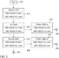
Das System verbleibt so lange in dem Zustand 210 bis seitens des Fahrers über die entsprechende Benutzerschnittstelle die hochautomatisierte Fahrfunktion angefordert wird. Dazu ergeht eine HAF-Anforderung durch die Hauptfunktion an das Steuergerät 110 des Primärbremssystems. Danach wechselt das System in den Zustand 220 "Init (Test)", wo eine Initialisierung des Testmodus stattfindet. Der Testmodus läuft wie folgt ab: Das Steuergerät 110 des Primärbremssystems deaktiviert seine Sensor-Schnittstelle und signalisiert dem Steuergerät 130 des Sekundärbremssystems über den Fahrzeugbus 140 den Eintritt in den Testmodus. Das Steuergerät 110 des Primärbremssystems sendet in dem Zustand des Testmodus keine Daten der Raddrehzahlsensoren 120 an das Steuergerät 130 des SBS. Das Steuergerät 130 des Sekundärbremssystem empfängt das Signal über den Eintritt in den Testmodus und stellt die Verbindung zu den Raddrehzahlsensoren 120 mit den Schalteinheiten 133 der Sensorik-Trennschaltung 136 her. Zusätzlich beginnt es die ausgewerteten Daten der Raddrehzahlsensoren 120 über den Fahrzeugbus 140 zu dem Steuergerät 110 des Primärsteuergerätes zu senden. Das Steuergerät 110 empfängt die Daten der Raddrehzahlsensoren 120 über den CAN-Bus. Über den Fahrzeugbus 140 wird auch das Einleiten des Testmodus an das Steuergerät 110 des Primärsteuergerätes zurück gemeldet. Das Steuergerät 110 des Primärbremssystems prüft die empfangenen Daten und signalisiert bei positivem Ergebnis das Ende des Testmodus an das Steuergerät 130 des SBS. Die Ausgestaltung kann in einem alternativen Ausführungsbeispiel auch so sein, dass der Wechsel zum Zustand 220 Init (Test) schon vor der HAF-Anforderung seitens des Fahrers geschieht um die Reaktionszeit ggü. dem Fahrer zu verkürzen. Auch eine wiederkehrende, zyklische Prüfung wäre möglich. Die Erfindung ist aber auch für das "vollautomatische Fahren" ab dem VDA-Level 5 einsetzbar, das ohne Fahrer auskommt.The system remains in the
Das Steuergerät 130 des Sekundärbremssystems empfängt dieses Signal, geht in den Zustand 240 "Normalbetrieb (HAF bereit)" über und trennt darin die Verbindung zu den Raddrehzahlsensoren 120. Das Steuergerät 110 des Primärbremssystem bekommt nun keine Sensordaten mehr über den Fahrzeugbus 140 und stellt im Zustand 240 "Normalbetrieb (HAF bereit)" daraufhin die Verbindung zu den Raddrehzahlsensoren 120 her. Es sendet seinerseits die Daten der Raddrehzahlsensoren 120 über den Fahrzeugbus 140 zu dem Steuergerät 130 des Sekundärbremssystems. Wenn die Daten der Raddrehzahlsensoren 120 korrekt empfangen werden, ist das Primärbremssystem fertig initialisiert und wechselt auch in den Zustand 240 "Normal (HAF)". In dem Zustand ist es für die automatisierte Fahrfunktion bereit. Das Steuergerät 130 des Sekundärbremssystems empfängt ab jetzt die Sensordaten über den Fahrzeugbus 140 und ist auch initialisiert. Die HAF Bereitschaft wird an die Fahrzeug -Hauptfunktion zurück gemeldet, von der die Anforderung für das Einleiten des HAF-Betriebes kam. Die automatisierte Fahrfunktion wird dann wie vom Fahrer gewünscht eingeleitet. Dieser Zustand wird dann bis zum Ende des Fahrzyklus im Schritt 245 beibehalten, wenn kein Fehler auftritt.The secondary
In dem Zustand 220 "Init (Test)" werden laufend die Daten, die vom Steuergerät 130 des Sekundärbremssystems empfangen werden, überprüft. Wenn diese Daten nicht mehr korrekt empfangen werden, erfolgt ein Wechsel in den Zustand 230 "Fehler: PBS ok". Der Fehlerfall wird also durch Wechsel in den sicheren Zustand des Primärbremssystems abgefangen. Darin ist das Steuergerät 110 des Primärbremssystems mit den Raddrehzahlsensoren 120 verbunden und die Daten der Raddrehzahlsensoren werden über den Fahrzeugbus 140 an das Steuergerät 130 des Sekundärbremssystems gesendet. Das Steuergerät 130 des Sekundärbremssystems testet den Eingang der Daten von den Raddrehzahlsensoren. Werden auch diese nicht mehr korrekt empfangen, liegt ein schwer wiegender Fehler vor, für den keine Heilung möglich ist. Der Test wird im Schritt 235 mit entsprechendem Ergebnis beendet. Es kann keine automatisierte Fahrfunktion eingeleitet werden.In
In dem Zustand 240 "Normal (HAF)" werden laufend die Daten, die vom Steuergerät 110 des Primärbremssystems empfangen werden, überprüft. Wenn diese Daten nicht mehr korrekt empfangen werden, erfolgt ein Wechsel in den Zustand 250 "Fehler: SBS ok". Der Fehlerfall wird also durch Wechsel in den sicheren Zustand des Sekundärbremssystems abgefangen. Darin ist das Steuergerät 130 des Sekundärbremssystems mit den Raddrehzahlsensoren 120 verbunden und die Daten der Raddrehzahlsensoren 120 werden über den Fahrzeugbus 140 an das Steuergerät 110 des Primärbremssystems gesendet. Das Steuergerät 110 des Primärbremssystems testet den Eingang der Daten von den Raddrehzahlsensoren 120. Werden auch diese nicht mehr korrekt empfangen, liegt ein schwer wiegender Fehler vor, für den keine Heilung möglich ist. Der Test wird im Schritt 255 mit entsprechendem Ergebnis beendet. Es kann keine automatisierte Fahrfunktion eingeleitet werden.In
Alle hierin erwähnten Beispiele wie auch bedingte Formulierungen sind ohne Einschränkung auf solche speziell angeführten Beispiele zu verstehen. So wird es zum Beispiel von Fachleuten anerkannt, dass das hier dargestellte Blockdiagramm eine konzeptionelle Ansicht einer beispielhaften Schaltungsanordnung darstellt. In ähnlicher Weise ist zu erkennen, dass ein dargestelltes Flussdiagramm, Zustandsübergangsdiagramm, Pseudocode und dergleichen verschiedene Varianten zur Darstellung von Prozessen darstellen, die im Wesentlichen in computerlesbaren Medien gespeichert und somit von einem Computer oder Prozessor ausgeführt werden können.All examples mentioned herein as well as conditional formulations are to be understood without limitation to such specifically mentioned examples. For example, it will be appreciated by those skilled in the art that the block diagram presented here represents a conceptual view of exemplary circuitry. Similarly, it will be appreciated that an illustrated flowchart, state transition diagram, pseudocode, and the like are various variants for representing processes that may be stored substantially in computer-readable media and thus executed by a computer or processor.
Es sollte verstanden werden, dass das vorgeschlagene Verfahren und die zugehörigen Vorrichtungen in verschiedenen Formen von Hardware, Software, Firmware, Spezialprozessoren oder einer Kombination davon implementiert werden können. Spezialprozessoren können anwendungsspezifische integrierte Schaltungen (ASICs), Reduced Instruction Set Computer (RISC) und / oder Field Programmable Gate Arrays (FPGAs) umfassen. Vorzugsweise wird das vorgeschlagene Verfahren und die Vorrichtung als eine Kombination von Hardware und Software implementiert. Die Software wird vorzugsweise als ein Anwendungsprogramm auf einer Programmspeichervorrichtung installiert. Typischerweise handelt es sich um eine Maschine auf Basis einer Computerplattform die Hardware aufweist, wie beispielsweise eine oder mehrere Zentraleinheiten (CPU), einen Direktzugriffsspeicher (RAM) und eine oder mehrere Eingabe/Ausgabe (I/O) Schnittstelle(n). Auf der Computerplattform wird typischerweise außerdem ein Betriebssystem installiert. Die verschiedenen Prozesse und Funktionen, die hier beschrieben wurden, können Teil des Anwendungsprogramms sein, oder ein Teil der über das Betriebssystem ausgeführt wird.It should be understood that the proposed method and apparatus may be implemented in various forms of hardware, software, firmware, special purpose processors, or a combination thereof. Special purpose processors may include Application Specific Integrated Circuits (ASICs), Reduced Instruction Set Computer (RISC), and / or Field Programmable Gate Arrays (FPGAs). Preferably, the proposed method and apparatus is implemented as a combination of hardware and software. The software is preferably installed as an application program on a program storage device. Typically, it is a machine based computer platform that includes hardware such as one or more central processing units (CPU), random access memory (RAM), and one or more input / output (I / O) interface (s). The computer platform also typically installs an operating system. The various processes and functions described herein may be part of the application program, or part that is executed via the operating system.
Die Offenbarung ist nicht auf die hier beschriebenen Ausführungsbeispiele beschränkt. Es gibt Raum für verschiedene Anpassungen und Modifikationen, die der Fachmann aufgrund seines Fachwissens als auch zu der Offenbarung zugehörend in Betracht ziehen würde.The disclosure is not limited to the embodiments described herein. There is room for various adjustments and modifications that would be considered by those skilled in the art, as well as to the disclosure.
- 100100
- Bremsvorrichtungbraking device
- 110110
- PrimärsteuergerätPrimary controller
- 111111
- Datenbus SekundärsteuergerätData bus secondary control unit
- 112112
- Anwendungsspezifischer Schaltkreis PrimärsteuergerätApplication specific circuit primary control unit
- 113113
- Schalteinheitswitching unit
- 114114
- Mikrocontrollermicrocontroller
- 115115
- Steuerleitungcontrol line
- 116116
- Sensorik-Trennschaltung PrimärsteuergerätSensor disconnect circuit Primary control unit
- 118118
- Überwachungsschaltungmonitoring circuit
- 120120
- Raddrehzahlsensorwheel speed sensor
- 122122
- Sensor-SignalleitungSensor signal line
- 130130
- SekundärsteuergerätSecondary controller
- 131131
- Datenbus PrimärsteuergerätData bus primary control unit
- 132132
- Anwendungsspezifischer Schaltkreis SekundärsteuergerätApplication specific circuit secondary control unit
- 133133
- Schalteinheitswitching unit
- 134134
- Mikrocontrollermicrocontroller
- 135135
- Steuerleitungcontrol line
- 136136
- Sensorik-Trennschaltung SekundärsteuergerätSensor disconnect circuit Secondary control unit
- 138138
- Überwachungsschaltungmonitoring circuit
- 140140
- Kommunikationsbuscommunication
- 200200
- Zustandsdiagrammstate diagram
- 210210
- Zustand Normalbetrieb ohne HAF BereitschaftCondition Normal operation without HAF readiness
- 220220
- Zustand TestmodusState test mode
- 230230
- Zustand Sicherer Betrieb über PrimärsteuergerätCondition Safe operation via primary control unit
- 240240
- Zustand Normalbetrieb mit HAF BereitschaftCondition Normal operation with HAF standby
- 250250
- Zustand Sicherer Betrieb über SekundärsteuergerätState Safe operation via secondary control unit
Claims (15)
Applications Claiming Priority (2)
| Application Number | Priority Date | Filing Date | Title |
|---|---|---|---|
| DE102017206035 | 2017-04-07 | ||
| DE102017209721.3A DE102017209721B4 (en) | 2017-04-07 | 2017-06-08 | Device for controlling a safety-relevant process, method for testing the functionality of the device, and motor vehicle with the device |
Publications (2)
| Publication Number | Publication Date |
|---|---|
| EP3385934A1 true EP3385934A1 (en) | 2018-10-10 |
| EP3385934B1 EP3385934B1 (en) | 2024-01-03 |
Family
ID=61683594
Family Applications (1)
| Application Number | Title | Priority Date | Filing Date |
|---|---|---|---|
| EP18161815.8A Active EP3385934B1 (en) | 2017-04-07 | 2018-03-14 | Device for controlling a safety-relevant process, method for testing the functionality of the device, and motor vehicle using the device |
Country Status (1)
| Country | Link |
|---|---|
| EP (1) | EP3385934B1 (en) |
Cited By (6)
| Publication number | Priority date | Publication date | Assignee | Title |
|---|---|---|---|---|
| CN110244685A (en) * | 2019-05-13 | 2019-09-17 | 思与行科技(苏州)有限公司 | The safety control circuit of controller for active electronic braking system |
| WO2020104277A1 (en) * | 2018-11-22 | 2020-05-28 | Robert Bosch Gmbh | Operating method for a redundant sensor assembly of a vehicle system and corresponding redundant sensor assembly |
| CN111824107A (en) * | 2019-04-18 | 2020-10-27 | 现代摩比斯株式会社 | Electro-hydraulic brake device and control method thereof |
| WO2021032338A1 (en) * | 2019-08-16 | 2021-02-25 | Robert Bosch Gmbh | Device and method for operating an automated parking brake with an actuator for a motor vehicle |
| CN114715102A (en) * | 2021-01-05 | 2022-07-08 | 广州汽车集团股份有限公司 | Vehicle redundant braking method and vehicle |
| WO2024056241A1 (en) * | 2022-09-12 | 2024-03-21 | Robert Bosch Gmbh | Method for operating a control unit for a parking brake system |
Citations (5)
| Publication number | Priority date | Publication date | Assignee | Title |
|---|---|---|---|---|
| DE19743463A1 (en) * | 1997-10-01 | 1999-04-08 | Itt Mfg Enterprises Inc | Fault identification method for microprocessor systems in motor vehicles |
| DE10065118A1 (en) * | 2000-12-28 | 2002-07-04 | Bosch Gmbh Robert | System and method for controlling and / or monitoring a control device network having at least two control devices |
| DE102015110965A1 (en) * | 2014-07-11 | 2016-01-14 | Ford Global Technologies, Llc | Speed in a vehicle regardless of failures |
| DE102014221901A1 (en) * | 2014-10-28 | 2016-04-28 | Robert Bosch Gmbh | Method for providing a sensor signal in the brake system in a vehicle |
| DE102015209565A1 (en) * | 2015-05-26 | 2016-12-01 | Robert Bosch Gmbh | Device and method for operating a motor vehicle |
-
2018
- 2018-03-14 EP EP18161815.8A patent/EP3385934B1/en active Active
Patent Citations (5)
| Publication number | Priority date | Publication date | Assignee | Title |
|---|---|---|---|---|
| DE19743463A1 (en) * | 1997-10-01 | 1999-04-08 | Itt Mfg Enterprises Inc | Fault identification method for microprocessor systems in motor vehicles |
| DE10065118A1 (en) * | 2000-12-28 | 2002-07-04 | Bosch Gmbh Robert | System and method for controlling and / or monitoring a control device network having at least two control devices |
| DE102015110965A1 (en) * | 2014-07-11 | 2016-01-14 | Ford Global Technologies, Llc | Speed in a vehicle regardless of failures |
| DE102014221901A1 (en) * | 2014-10-28 | 2016-04-28 | Robert Bosch Gmbh | Method for providing a sensor signal in the brake system in a vehicle |
| DE102015209565A1 (en) * | 2015-05-26 | 2016-12-01 | Robert Bosch Gmbh | Device and method for operating a motor vehicle |
Cited By (8)
| Publication number | Priority date | Publication date | Assignee | Title |
|---|---|---|---|---|
| WO2020104277A1 (en) * | 2018-11-22 | 2020-05-28 | Robert Bosch Gmbh | Operating method for a redundant sensor assembly of a vehicle system and corresponding redundant sensor assembly |
| CN111824107A (en) * | 2019-04-18 | 2020-10-27 | 现代摩比斯株式会社 | Electro-hydraulic brake device and control method thereof |
| US11491957B2 (en) * | 2019-04-18 | 2022-11-08 | Hyundai Mobis Co., Ltd. | Electronic hydraulic brake device and control method thereof |
| CN111824107B (en) * | 2019-04-18 | 2022-11-29 | 现代摩比斯株式会社 | Electro-hydraulic brake device and control method thereof |
| CN110244685A (en) * | 2019-05-13 | 2019-09-17 | 思与行科技(苏州)有限公司 | The safety control circuit of controller for active electronic braking system |
| WO2021032338A1 (en) * | 2019-08-16 | 2021-02-25 | Robert Bosch Gmbh | Device and method for operating an automated parking brake with an actuator for a motor vehicle |
| CN114715102A (en) * | 2021-01-05 | 2022-07-08 | 广州汽车集团股份有限公司 | Vehicle redundant braking method and vehicle |
| WO2024056241A1 (en) * | 2022-09-12 | 2024-03-21 | Robert Bosch Gmbh | Method for operating a control unit for a parking brake system |
Also Published As
| Publication number | Publication date |
|---|---|
| EP3385934B1 (en) | 2024-01-03 |
Similar Documents
| Publication | Publication Date | Title |
|---|---|---|
| DE102017209721B4 (en) | Device for controlling a safety-relevant process, method for testing the functionality of the device, and motor vehicle with the device | |
| EP3385934B1 (en) | Device for controlling a safety-relevant process, method for testing the functionality of the device, and motor vehicle using the device | |
| EP2183136B1 (en) | Brake system for a vehicle and a method for the operation of a brake system for a vehicle | |
| EP2176106B1 (en) | Brake system for a vehicle and method for operating a brake system for a vehicle | |
| EP2786225B1 (en) | Method for operating at least two data processing units with high availability, in particular in a vehicle, and device for operating a machine | |
| EP3691945B1 (en) | Vehicle brake system and method of operating | |
| EP3584140B1 (en) | Vehicle and method and apparatus for controlling a safety-relevant process | |
| DE19634567B4 (en) | Electric brake system | |
| EP1763454B1 (en) | Redundant data bus system | |
| DE102013020177A1 (en) | Motor car, has sensor systems actuated by main control unit in nominal operating mode, and replacement control unit controlling sensor systems if mistake arises in main control unit in emergency operation state | |
| DE102020116410A1 (en) | Device for controlling a brake of an autonomous vehicle | |
| WO2014033172A1 (en) | Method for carrying out a safety function of a vehicle and system for carrying out the method | |
| DE102005005995A1 (en) | Method and device for monitoring signal processing units for sensors | |
| WO2016188664A1 (en) | Device and method for operating a motor vehicle | |
| DE102017119408A1 (en) | BRAKE-BY-WIRE SYSTEM | |
| DE102012200184A1 (en) | Safe operation of a motor vehicle | |
| DE102018220605B4 (en) | Motor vehicle network and method for operating a motor vehicle network | |
| DE2824168B2 (en) | Device for controlling track-bound vehicles in train sets | |
| DE102019104948A1 (en) | Communication system and method for communication for a motor vehicle | |
| DE102020213129A1 (en) | Control unit of an at least partially automated vehicle | |
| WO2024002731A2 (en) | Vehicle network for data communication between components of a vehicle, and system and vehicle therewith and method therefor | |
| DE102022124559A1 (en) | Trailer network system for data communication in a trailer vehicle and trailer vehicle therewith and method therefor | |
| DE102021206379A1 (en) | Control device and assistance system for a vehicle | |
| EP1213199B1 (en) | Power supply for electronic control circuit and for drive circuit of a wheel brake actuator | |
| DE102022203259A1 (en) | Method and device for securing automatic driving functions of a motor vehicle |
Legal Events
| Date | Code | Title | Description |
|---|---|---|---|
| PUAI | Public reference made under article 153(3) epc to a published international application that has entered the european phase |
Free format text: ORIGINAL CODE: 0009012 |
|
| STAA | Information on the status of an ep patent application or granted ep patent |
Free format text: STATUS: THE APPLICATION HAS BEEN PUBLISHED |
|
| AK | Designated contracting states |
Kind code of ref document: A1 Designated state(s): AL AT BE BG CH CY CZ DE DK EE ES FI FR GB GR HR HU IE IS IT LI LT LU LV MC MK MT NL NO PL PT RO RS SE SI SK SM TR |
|
| AX | Request for extension of the european patent |
Extension state: BA ME |
|
| STAA | Information on the status of an ep patent application or granted ep patent |
Free format text: STATUS: REQUEST FOR EXAMINATION WAS MADE |
|
| 17P | Request for examination filed |
Effective date: 20190410 |
|
| RBV | Designated contracting states (corrected) |
Designated state(s): AL AT BE BG CH CY CZ DE DK EE ES FI FR GB GR HR HU IE IS IT LI LT LU LV MC MK MT NL NO PL PT RO RS SE SI SK SM TR |
|
| STAA | Information on the status of an ep patent application or granted ep patent |
Free format text: STATUS: EXAMINATION IS IN PROGRESS |
|
| 17Q | First examination report despatched |
Effective date: 20210609 |
|
| STAA | Information on the status of an ep patent application or granted ep patent |
Free format text: STATUS: EXAMINATION IS IN PROGRESS |
|
| RIN1 | Information on inventor provided before grant (corrected) |
Inventor name: GRIESER-SCHMITZ, STEFAN Inventor name: TSCHIENE, ALEXANDER |
|
| RAP1 | Party data changed (applicant data changed or rights of an application transferred) |
Owner name: ZF ACTIVE SAFETY GMBH Owner name: VOLKSWAGEN AKTIENGESELLSCHAFT |
|
| GRAP | Despatch of communication of intention to grant a patent |
Free format text: ORIGINAL CODE: EPIDOSNIGR1 |
|
| STAA | Information on the status of an ep patent application or granted ep patent |
Free format text: STATUS: GRANT OF PATENT IS INTENDED |
|
| INTG | Intention to grant announced |
Effective date: 20230906 |
|
| RIN1 | Information on inventor provided before grant (corrected) |
Inventor name: GRIESER-SCHMITZ, STEFAN Inventor name: TSCHIENE, ALEXANDER |
|
| GRAS | Grant fee paid |
Free format text: ORIGINAL CODE: EPIDOSNIGR3 |
|
| GRAA | (expected) grant |
Free format text: ORIGINAL CODE: 0009210 |
|
| STAA | Information on the status of an ep patent application or granted ep patent |
Free format text: STATUS: THE PATENT HAS BEEN GRANTED |
|
| AK | Designated contracting states |
Kind code of ref document: B1 Designated state(s): AL AT BE BG CH CY CZ DE DK EE ES FI FR GB GR HR HU IE IS IT LI LT LU LV MC MK MT NL NO PL PT RO RS SE SI SK SM TR |
|
| REG | Reference to a national code |
Ref country code: GB Ref legal event code: FG4D Free format text: NOT ENGLISH |
|
| P01 | Opt-out of the competence of the unified patent court (upc) registered |
Effective date: 20231130 |
|
| REG | Reference to a national code |
Ref country code: DE Ref legal event code: R096 Ref document number: 502018013891 Country of ref document: DE |
|
| REG | Reference to a national code |
Ref country code: CH Ref legal event code: EP |
|
| REG | Reference to a national code |
Ref country code: IE Ref legal event code: FG4D Free format text: LANGUAGE OF EP DOCUMENT: GERMAN |
|
| REG | Reference to a national code |
Ref country code: LT Ref legal event code: MG9D |