EP3385920A1 - System und verfahren zum energiesparen bei zugangskontrollprodukten - Google Patents
System und verfahren zum energiesparen bei zugangskontrollprodukten Download PDFInfo
- Publication number
- EP3385920A1 EP3385920A1 EP18164355.2A EP18164355A EP3385920A1 EP 3385920 A1 EP3385920 A1 EP 3385920A1 EP 18164355 A EP18164355 A EP 18164355A EP 3385920 A1 EP3385920 A1 EP 3385920A1
- Authority
- EP
- European Patent Office
- Prior art keywords
- access
- access control
- building
- readers
- access controller
- Prior art date
- Legal status (The legal status is an assumption and is not a legal conclusion. Google has not performed a legal analysis and makes no representation as to the accuracy of the status listed.)
- Granted
Links
Images


Classifications
-
- G—PHYSICS
- G08—SIGNALLING
- G08B—SIGNALLING SYSTEMS, e.g. PERSONAL CALLING SYSTEMS; ORDER TELEGRAPHS; ALARM SYSTEMS
- G08B13/00—Burglar, theft or intruder alarms
- G08B13/22—Electrical actuation
-
- G—PHYSICS
- G06—COMPUTING OR CALCULATING; COUNTING
- G06F—ELECTRIC DIGITAL DATA PROCESSING
- G06F1/00—Details not covered by groups G06F3/00 - G06F13/00 and G06F21/00
- G06F1/26—Power supply means, e.g. regulation thereof
- G06F1/32—Means for saving power
- G06F1/3203—Power management, i.e. event-based initiation of a power-saving mode
- G06F1/3206—Monitoring of events, devices or parameters that trigger a change in power modality
-
- G—PHYSICS
- G06—COMPUTING OR CALCULATING; COUNTING
- G06F—ELECTRIC DIGITAL DATA PROCESSING
- G06F1/00—Details not covered by groups G06F3/00 - G06F13/00 and G06F21/00
- G06F1/26—Power supply means, e.g. regulation thereof
- G06F1/32—Means for saving power
- G06F1/3203—Power management, i.e. event-based initiation of a power-saving mode
- G06F1/3234—Power saving characterised by the action undertaken
- G06F1/325—Power saving in peripheral device
-
- G—PHYSICS
- G07—CHECKING-DEVICES
- G07C—TIME OR ATTENDANCE REGISTERS; REGISTERING OR INDICATING THE WORKING OF MACHINES; GENERATING RANDOM NUMBERS; VOTING OR LOTTERY APPARATUS; ARRANGEMENTS, SYSTEMS OR APPARATUS FOR CHECKING NOT PROVIDED FOR ELSEWHERE
- G07C9/00—Individual registration on entry or exit
- G07C9/00174—Electronically operated locks; Circuits therefor; Nonmechanical keys therefor, e.g. passive or active electrical keys or other data carriers without mechanical keys
-
- G—PHYSICS
- G07—CHECKING-DEVICES
- G07C—TIME OR ATTENDANCE REGISTERS; REGISTERING OR INDICATING THE WORKING OF MACHINES; GENERATING RANDOM NUMBERS; VOTING OR LOTTERY APPARATUS; ARRANGEMENTS, SYSTEMS OR APPARATUS FOR CHECKING NOT PROVIDED FOR ELSEWHERE
- G07C9/00—Individual registration on entry or exit
- G07C9/00174—Electronically operated locks; Circuits therefor; Nonmechanical keys therefor, e.g. passive or active electrical keys or other data carriers without mechanical keys
- G07C9/00571—Electronically operated locks; Circuits therefor; Nonmechanical keys therefor, e.g. passive or active electrical keys or other data carriers without mechanical keys operated by interacting with a central unit
-
- G—PHYSICS
- G07—CHECKING-DEVICES
- G07C—TIME OR ATTENDANCE REGISTERS; REGISTERING OR INDICATING THE WORKING OF MACHINES; GENERATING RANDOM NUMBERS; VOTING OR LOTTERY APPARATUS; ARRANGEMENTS, SYSTEMS OR APPARATUS FOR CHECKING NOT PROVIDED FOR ELSEWHERE
- G07C9/00—Individual registration on entry or exit
- G07C9/20—Individual registration on entry or exit involving the use of a pass
-
- F—MECHANICAL ENGINEERING; LIGHTING; HEATING; WEAPONS; BLASTING
- F24—HEATING; RANGES; VENTILATING
- F24F—AIR-CONDITIONING; AIR-HUMIDIFICATION; VENTILATION; USE OF AIR CURRENTS FOR SCREENING
- F24F11/00—Control or safety arrangements
- F24F11/30—Control or safety arrangements for purposes related to the operation of the system, e.g. for safety or monitoring
- F24F11/46—Improving electric energy efficiency or saving
-
- F—MECHANICAL ENGINEERING; LIGHTING; HEATING; WEAPONS; BLASTING
- F24—HEATING; RANGES; VENTILATING
- F24F—AIR-CONDITIONING; AIR-HUMIDIFICATION; VENTILATION; USE OF AIR CURRENTS FOR SCREENING
- F24F2120/00—Control inputs relating to users or occupants
- F24F2120/10—Occupancy
-
- G—PHYSICS
- G07—CHECKING-DEVICES
- G07C—TIME OR ATTENDANCE REGISTERS; REGISTERING OR INDICATING THE WORKING OF MACHINES; GENERATING RANDOM NUMBERS; VOTING OR LOTTERY APPARATUS; ARRANGEMENTS, SYSTEMS OR APPARATUS FOR CHECKING NOT PROVIDED FOR ELSEWHERE
- G07C9/00—Individual registration on entry or exit
- G07C9/00174—Electronically operated locks; Circuits therefor; Nonmechanical keys therefor, e.g. passive or active electrical keys or other data carriers without mechanical keys
- G07C2009/00579—Power supply for the keyless data carrier
-
- G—PHYSICS
- G07—CHECKING-DEVICES
- G07C—TIME OR ATTENDANCE REGISTERS; REGISTERING OR INDICATING THE WORKING OF MACHINES; GENERATING RANDOM NUMBERS; VOTING OR LOTTERY APPARATUS; ARRANGEMENTS, SYSTEMS OR APPARATUS FOR CHECKING NOT PROVIDED FOR ELSEWHERE
- G07C9/00—Individual registration on entry or exit
- G07C9/00174—Electronically operated locks; Circuits therefor; Nonmechanical keys therefor, e.g. passive or active electrical keys or other data carriers without mechanical keys
- G07C9/00896—Electronically operated locks; Circuits therefor; Nonmechanical keys therefor, e.g. passive or active electrical keys or other data carriers without mechanical keys specially adapted for particular uses
- G07C9/00904—Electronically operated locks; Circuits therefor; Nonmechanical keys therefor, e.g. passive or active electrical keys or other data carriers without mechanical keys specially adapted for particular uses for hotels, motels, office buildings or the like
-
- H—ELECTRICITY
- H04—ELECTRIC COMMUNICATION TECHNIQUE
- H04W—WIRELESS COMMUNICATION NETWORKS
- H04W52/00—Power management, e.g. Transmission Power Control [TPC] or power classes
- H04W52/02—Power saving arrangements
Definitions
- Security systems are often installed within and around buildings such as commercial, residential, or governmental buildings. Examples of these buildings include offices, hospitals, warehouses, schools or universities, shopping malls, government offices, and casinos.
- the security systems typically include components such as access control systems, surveillance cameras, image analytics systems, network video recorders (NVRs), security alarm panels and devices connected to those panels to list a few examples.
- NVRs network video recorders
- the security devices of the security alarm panels include motion sensor devices and relays, for example.
- Motion sensor devices can detect intrusions and relays can detect door or windows being opened. These devices are used to detect unauthorized access to the premises, and send indications of the intrusions to the security panel.
- Access control systems in buildings are principally concerned with physical security and the selective access to, restriction of, and/or notification of access to an area or other resource.
- each employee or other individual can have different levels of security access based on their job function, and the access control system can enforce these access policies at the level of the individual access control readers.
- an accounting employee may obtain access to a workplace building via an access control reader located at the perimeter of the building. Once inside, however, the same employee is not authorized to access an engineering area or physical plant maintenance area of the building, the access to which is controlled by access control readers that restrict access to authorized individuals typically having only engineering and plant maintenance job functions, respectively.
- the main components of the access control systems are access control readers and possibly door controllers.
- the access control readers are installed near access points, such as doors or hallways or elevators, and enable presentation of credentials to obtain access to restricted areas such as buildings or areas of the buildings.
- individuals interact with the access control readers by swiping keycards or bringing contactless smart cards within range (approximately 2-3 inches or 5 centimeters) of the reader.
- frictionless access control systems have become common.
- user devices such as smart phones or wireless fobs, transmit credentials to nearby readers.
- the access control readers read the credential information of the users and validate the information possibly by reference to a verification database maintained by an access controller, which confirms the credentials and determines if the individuals are authorized to access the restricted areas. If the individuals are authorized, then the access control readers might signal door controllers to unlock doors or to not generate alarms, in examples.
- the access control readers can often be controlled in different ways and can typically receive input power in different ways.
- a keycard access control reader can be both controlled by and receive its source of input power from a dedicated output interface/control line of the access controller.
- the access controller can provide a switched source of 12VDC or 24VDCto each keycard access control reader via the dedicated output/control line.
- a networked access control reader can receive its control signals over an open, internet protocol (IP) network such as a Local Area Network (LAN) and also has an independent source of input power.
- IP internet protocol
- LAN Local Area Network
- a smart card access control reader is controlled by an access controller but relies on an external power module as its source of input power.
- the power module is also controlled by the access control controller and provides a switched source input power such as 12/24VDC to the smart card access control reader.
- access control readers are typically on all the time, i.e. 24 hours a day, 365 days a year, and large buildings such as college campuses, government archives, and office buildings can have possibly hundreds or even thousands of access control readers, the amount of power consumed by the access control readers collectively can be significant.
- a power saving state is a state in which the source of input power is temporarily disabled, such as being suspended or switched off, in response to a condition being satisfied. The source of input power can then be quickly resumed or switched back on once the condition is no longer satisfied.
- the present invention can first identify which of its access control readers control access to the building, otherwise known as peripheral access control readers, and which of its access control readers control access to interior areas within a building, otherwise known as internal access control readers. Then, when a condition is satisfied, such as the access controller assessing that the building is unoccupied, the security system can place some of the access control readers (such as some or all of its internal access control readers) into a power saving state to save on power consumption.
- a building is assessed to be unoccupied in different ways.
- a building is assessed to be unoccupied in response to the access controller determining that no individuals have entered or exited the building via perimeter access control readers over a predetermined time period, such as from a time immediately after normal work hours up until a time just prior to the starting hour of the next work day.
- a building is assessed to be unoccupied when the access controller receives a signal sent by the security alarm panel indicating that the security system is armed.
- the assessment that the building is unoccupied acts as a trigger for the access controller to place its access control readers in a power saving state.
- the security alarm panel receives indications of intrusion at the building from security devices deployed at the building.
- an individual can both arm and disarm the security system via arm and disarm commands sent to the security alarm panel, in examples.
- the invention features a security system.
- the security system includes access control readers and an access controller.
- the access control readers control access to a building and/or to interior areas of the building, and the access controller places the access control readers into power saving state when the building is assessed to be unoccupied.
- the access control readers include interior access control readers that control access to the interior areas of the building and perimeter access control readers that control access to the building.
- the access controller places only the interior access control readers into power saving state when the building is assessed to be unoccupied.
- the building is assessed to be unoccupied in response to the access controller receiving a signal indicating that the security system is armed.
- the building is assessed to be unoccupied by the access controller receiving indications that individuals have entered and/or exited the building sent from access control readers, where the access controller increments an enter count in response to receiving the indication for each individual entering the building and increments an exit count in response to receiving the indication for each individual exiting the building, and by the access controller identifying that the entrance count and the exit count are equal.
- the access controller places the access control readers into power saving state by disabling control lines of the access controller that control and provide power to the access control readers.
- the access controller places the access control readers into power saving state by sending a power disabling control signal to a power module that provides power to the access control readers. Additionally and/or alternatively, the access controller places the access control readers into power saving state by sending a sleep signal over a network to the access control readers.
- the security system also includes a security alarm panel that receives indications of intrusions at the building from security devices and that sends alarm signals in response, wherein the access controller places the access control readers out of power saving state in response to the access controller receiving the alarm signals.
- the security alarm panel can also send a signal indicating that the security system is disarmed, wherein the access controller places the access control readers out of power saving state in response to the access controller receiving the disarm signal.
- the invention features a method for a security system.
- the method comprises access control readers controlling access to a building and/or to interior areas of the building, and an access controller placing the access control readers into power saving state when the building is assessed to be unoccupied.
- the invention features a security system for a premises.
- the security system includes access control readers and an access controller.
- the access control readers control access points of a building, wherein the access points enable access to the premises and/or areas within the premises.
- the access controller places the access control readers into power saving state based upon locations of the access points relative to the premises when the building is assessed to be unoccupied.
- the term “and/or” includes any and all combinations of one or more of the associated listed items. Further, the singular forms and the articles “a”, “an” and “the” are intended to include the plural forms as well, unless expressly stated otherwise. It will be further understood that the terms: includes, comprises, including and/or comprising, when used in this specification, specify the presence of stated features, integers, steps, operations, elements, and/or components, but do not preclude the presence or addition of one or more other features, integers, steps, operations, elements, components, and/or groups thereof. Further, it will be understood that when an element, including component or subsystem, is referred to and/or shown as being connected or coupled to another element, it can be directly connected or coupled to the other element or intervening elements may be present.
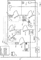
- Fig. 1 shows a security system 20 to which the invention is applicable.
- the security system 20 includes an access controller 114 that controls multiple access control readers deployed at a building 90.
- the access controller 114 has an interface that enables communications over an enterprise network 50 such as a Local Area Network (LAN) using proprietary and/or standard communications protocols such as Internet Protocol (IP)/Ethernet.
- IP Internet Protocol
- the access controller 114 stores information for individuals and the access control readers to a database 70.
- Identity card access control reader 18-p is connected to control line 44-1 of the access controller 114.
- the access controller 114 also maintains an enter count 32 and an exit count 42 for individuals entering and leaving the building via identity card access control reader 18-p.
- Control line 44-1 not only controls the identity card access control reader 18-p but also is the source of input power for the reader 18-p.
- Identity card access control reader 18-p is located near the perimeter of the building 90 and controls access to building 90 via access point 24-p. Access point 24-p enables access to foyer 40 of the building 90, through which all individuals typically enter and exit during a work day, in one example.
- the identity card access control reader 18-p can be a keycard identity reader, smart card reader, or any other type of access card reader.
- Frictionless access control reader 48 is connected to control line 44-2 of the access controller 114. Control line 44-1 not only controls the frictionless access control reader 48 but also is the source of input power for the reader 48. Frictionless access control reader 48 is located near access point 24-1-1 and controls access to interior room1 30-1 through access point 24-1-1. To obtain access, an individual 60 carrying a mobile device 105 including credentials of the individual must present the mobile device 105 within a threshold area of the frictionless access control reader 48. The credentials of the user are then communicated wirelessly (indicated by reference 106) from the mobile device 105 to the reader 48 using various wireless protocols such as Bluetooth and Wi-Fi, in examples.
- various wireless protocols such as Bluetooth and Wi-Fi
- Networked access control reader 68 is connected to enterprise network 50 and receives its control signals over the network 50 from the access controller 114.
- the networked access control reader 68 has an independent source of input power.
- the reader 68 also receives its source of input power via its connection to the network 50, where the access controller 114 provides switched Power over Ethernet (PoE) as the source of input power, in one implementation.
- Networked access control reader 68 is located near access point 24-1-2 and controls access to interior room1 30-1 through access point 24-1-2.
- the physical reader mechanism can be a keycard identity reader, smart card reader, or any other type of access card reader.
- Biometric access control reader 28 is connected to control line 44-3 of the access controller 114. Control line 44-3 not only controls the biometric access control reader 28 but also is the source of input power for the reader 28, in one implementation. Biometric access control reader 28 is located near access point 24-3 and controls access to interior room3 30-3 through access point 24-3. To obtain access, the reader 28 scans a physical attribute of an individual such as a fingerprint or an iris 36 of the individual.
- Identity card access control reader 18-1 is located near access point 24-2 and controls access to room2 30-2 via access point 24-2.
- the identity card access control reader 18-1 is a keycard identity reader that accepts a keycard 12 which includes credentials of the individual.
- Identity card access control reader 18-1 is connected to control line 44-4 of the access controller 114. Control line 44-4 not only controls the identity card access control reader 18-1 but also is the source of input power for the reader 18-1, in one implementation.
- the access controller 114 can also be integrated with a security alarm panel 102.
- security alarm panel 102 has an interface on the enterprise network 50, which enables communications with the access controller 114.
- a security keypad 38 allows individuals to change an alarm state of the security system 20 via the security alarm panel 102, where individuals can use the security keypad 38 to place the security system 20 in an armed or disarmed state maintained by the security alarm panel 102.
- the security control panel 102 controls and receives indications of intrusions from security devices deployed within the building 90.
- the indications of intrusions are sent from the security devices to the security alarm panel 102 via security device bus 10.
- Security devices include motion sensor devices 110, surveillance cameras 103, and possibly door controllers in examples.
- Motion sensor device 110-1 is located in room2 30-2 and monitors for intrusions within room2 30-2.
- Motion sensor device 110-2 is located in room3 30-3 and monitors for intrusions within room3 30-3.
- Surveillance camera 103 is located in room1 30-1 and monitors for intrusions within room1 30-1.
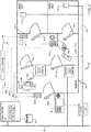
- Fig. 2 shows another example of a security system 20 to which the invention is applicable.
- the security system 20 includes similar components as in Fig. 1 . There are some differences in Fig. 2 , however.
- the identity card access control reader 18-1 of Fig.1 that controls access to room2 30-2 has been replaced in Fig. 2 with identity card access control reader 18-2.
- reader 18-2 is also controlled by control line 44-4 of the access controller 114.
- reader 18-2 receives its source of input power from a power module 46, where the source of input power is indicated by reference 26.
- the power module 46 is controlled by the access controller 114 via one of its control lines (here, 44-5).
- the power module 46 provides switched power 26 to the identity card access control reader 18-2.
- the power module itself is preferably powered by 120VAC, and can provide different types of switched power 26 including 12/24 VDC, in examples.
- Fig. 3 shows exemplary contents of an access control reader table 80 maintained by the access controllers 114 in Fig. 1 and Fig. 2 .
- the access control reader table 80 is included within a database 70.
- An entry 33 for each access control reader in the security systems of Fig. 1 and Fig. 2 is maintained within the access control reader table 80.
- Each entry 33 includes an access control reader name, ID number, location within the building 90, and a value indicating whether the associated access control reader enables access to the building 90 (e.g. is a perimeter access control reader) or enables access to interior areas such as rooms 30 within the building (e.g. is an internal access control reader).
- the ID number is a unique value associated with each access control reader in the security system 20.
- the ID number can be a Media Access Control (MAC) address for an IP/Ethernet enabled access control reader, a Wiegand ID for legacy identity card access control readers, or a proprietary ID number that is unique across all access control readers in the security system 20.
- MAC Media Access Control
- Entry 33-1 for frictionless access control reader 48 includes ID number 0x0001, location information indicating that the reader 48 controls access to room1 30-1, and indicates (e.g. has value of 1) that the reader 48 is an internal access control reader.
- Entry 33-2 for biometric access control reader 28 includes ID number 0x0002, location information indicating that the reader 28 controls access to room3 30-3, and indicates (e.g. has value of 1) that the reader 28 is an internal access control reader.
- entry 33-3 for identity card access control reader 18-1 includes ID number 0x0003, location information indicating that the reader 18-1 controls access to room2 30-2, and indicates (e.g. has value of 1) that the reader 18-1 is an internal access control reader.
- Entry 33-4 for identity access control reader 18-2 includes ID number 0x0004, location information indicating that the reader 18-2 controls access to room2 30-2, and indicates (e.g. has value of 1) that the reader 18-2 is an internal access control reader.
- entry 33-5 for identity card access control reader 18-p includes ID number 0x0005, location information indicating that the reader 18-p controls access to the building 90, and indicates (e.g. has value of 0) that the reader 18-p is a perimeter access control reader.
- entry 33-6 for networked access control reader 68 includes ID number 0x0006, location information indicating that the reader 68 controls access to room1 30-1, and indicates (e.g. has value of 1) that the reader 68 is an internal access control reader.
- Fig. 4 is a sequence diagram that illustrates one example of operation for the security system 20 of Fig. 1 .
- the security system 20 can place different access control readers in a power saving state in response to the access controller 114 assessing that the building 90 is unoccupied.
- the building is assessed as being unoccupied in response to the access controller 114 receiving a signal from the security alarm panel 102 indicating that the security system 20 is in an armed state.
- the access controller 114 can at least place the interior access control readers in a power saving state to save energy, because no individuals are present to access the interior rooms 30 to which the interior access control readers provide access.
- the access controller 114 places the access control readers out of power saving state.
- the security alarm panel 102 receives a command to activate the alarm/place the security system in an armed state.
- the command is sent by the security keypad 38 by an individual that is the last to leave the building 90 on a normal work day, for example.
- the security alarm panel 102 sends a signal over the network 50 indicating that the security system 20 is armed (i.e. set to an armed state), which the access controller 114 receives over the network 50.
- the access controller 114 In response to receiving the signal over the network 50 indicating the security system 50 is armed, the access controller 114 obtains the contents of the access reader table 80 in step 306.
- Step 308 describes examples for how access control readers of different types can be placed into a power saving mode by the access controller 114.
- the access controller 114 places only the interior access control readers into power saving state when the building 90 is assessed to be unoccupied.
- step 308-1 for each access control reader that receives its input power from a control line 44 of the access controller 114, the access controller 114 executes a lookup of the access control readers against entries 33 in the access reader table 80.
- the access controller 114 matches the access control readers with an associated internal access control reader in the table 80, and places each matching reader in a power saving state by disabling (such as by switching off) the power output of the control line 44 that connects to the matching access control reader.
- the access controller 114 determines a match between an access control reader and an associated entry 33 for an access control reader in the table 80 by matching the unique ID number of the access control reader with an ID number included within an entry 33.
- the access controller 114 places the identity card access control reader 18-p, the frictionless access control reader 48, the biometric access control reader 28, and the identity card access control reader 18-1 in a power saving state by switching off the power signal normally sent over control lines 44-1, 44-2, 44-3, and 44-4, respectively.
- step 308-2 the access controller 114 places access control readers in a power saving state by sending a "sleep" command to each networked access control reader 68 matching an associated internal access control reader in the table 80.
- access points 24 such as doors are locked when their associated access control reader is placed in a power saving state.
- motion sensor 110-1 detects motion within room2 30-2 and sends an indication of intrusion over the security bus 10 to the security alarm panel 102.
- the security alarm panel 102 receives the indication of intrusion in step 310, and generates an alarm signal over the network 50 in response.
- step 312 the access controller 114 receives the alarm signal sent by the security control panel 102 over the network 50.
- the access controller 114 in step 314-1, places the access control readers referenced in step 308-1 out of power saving state by resuming / switching back on the source of input power to control lines 44-1 through 44-4, in one example.
- the access controller 112 sends an "awake" command over the network 50 to each networked access control reader 68 to place the readers 68 out of power saving state.
- Fig. 5 is a sequence diagram that illustrates another example of operation of the security system 20 in Fig.1 .
- the security system 20 via its access controller 114, places different access control readers in a power saving state.
- the access controller 114 places the access control readers in a power saving state in response to the access controller 114 assessing that the building 90 is unoccupied.
- the building is assessed as being unoccupied, in one example, in response to the access controller 114 receiving a signal from the security alarm panel 102 indicating that the security system 20 is in an armed state.
- the access controller 114 places the access control readers out of power saving state in response to a different condition being satisfied than in Fig. 4 .
- the access controller 114 places the access control readers out of power saving state in response to receiving a signal indicating that the security system 20 is disarmed/set to a disarmed state.
- the security alarm panel 102 receives a command to activate the alarm/place the security system 20 in an armed state.
- a command to activate the alarm/place the security system 20 in an armed state In the example, an individual that is the last to leave the building 90 on a normal work day, for example, enters the command via the security keypad 38.
- the security alarm panel 102 in response to the security alarm panel 102 receiving the command, the security alarm panel 102 sends a signal over the network 50 indicating that the security system 20 is armed (i.e. set to an armed state), which the access controller 114 receives over the network 50.
- the access controller 114 In response to receiving the signal over the network 50 indicating that the security system 20 is armed, the access controller 114 obtains the contents of the access reader table 80 in step 334.
- Step 336 describes examples for how access control readers of different types can be placed into a power saving state by the access controller 114.
- step 336-1 for each access control reader that receives its input power from a control line 44 of the access controller 114, the access controller 114 executes a lookup of the access control readers against entries 33 in the access reader table 80.
- the access controller 114 matches the access control readers with an associated internal access control reader in the table 80, and places each matching reader in a power saving state by disabling the power output of the control line that connects to the matching access control reader, in one example.
- the access controller 114 places the identity card access control reader 18-p, the frictionless access control reader 48, the biometric access control reader 28, and the identity card access control reader 18-1 in a power saving state by switching off the power signal normally sent over control lines 44-1, 44-2, 44-3, and 44-4, respectively.
- step 336-2 the access controller 114 places access control readers in a power saving state by sending a "sleep" command to each networked access control reader 68 matching an associated internal access control reader in the table 80.
- step 338 the security alarm panel 102 receives the command to deactivate the alarm, and in response, sends a signal indicating that the security system 20 is disarmed (i.e. set to disarmed state) over the enterprise network 50 in step 340.
- the access controller 114 In response to receiving the signal over the network 50 indicating the security system 20 is disarmed, the access controller 114, in step 342-1, places the access control readers referenced in step 336-1 out of power saving state by resuming / switching back on the source of input power to control lines 44-1 through 44-4, in one example. Also in response, in step 342-2, the access controller 112 sends an "awake" command over the network 50 to each networked access control reader 68 to place the readers 68 out of power saving state.
- Fig. 6 is a sequence diagram that illustrates an example of operation of the security system 20 in Fig. 2 .
- the access controller114 receives a command to activate the alarm/place the security system 20 in an armed state.
- the command to arm the system is sent by the identity card access control reader 18-p to access control panel 114.
- the command is sent in response to an individual executing a "double swipe" of a key card 12 at identity card access control reader 18-p, which is located near the perimeter of the building 90.
- the individual is the last individual to exit the building in a normal work day, in one example.
- step 352 the access controller 114 then sends a signal over the network 50 to activate the alarm.
- the security alarm panel 102 Upon receiving this signal in step 354, the security alarm panel 102 sends a signal over the network 50 indicating that the security system 20 is armed (i.e. set to an armed state), which the access controller 114 then receives over the network 50.
- the access controller 114 In response to receiving the signal over the network 50 indicating that the security system 20 is armed, the access controller 114 obtains the contents of the access reader table 80 in step 356.
- Step 358 describes examples for how access control readers of different types can be placed into a power saving mode by the access controller 114.
- step 358-1 for each access control reader that receives its input power from a control line 44 of the access controller 114, the access controller 114 executes a lookup of the access control readers against entries 33 in the access reader table 80.
- the access controller 114 matches the access control readers with an associated internal access control reader in the table 80, and places each matching reader in a power saving state by disabling the power output of the control line that connects to the matching access control reader.
- the access controller 114 places the identity card access control reader 18-p, the frictionless access control reader 48, and the biometric access control reader 28 in a power saving state by switching off the power signal normally sent over control lines 44-1, 44-2, and 44-3, respectively.
- step 358-2 for each access control reader that receives its source of input power from a power module 46, the access controller 114 matches the access control reader with an associated internal access control reader in the table 80, and places each matching access control reader in a power saving state.
- the access controller 114 places each matching access control reader in a power saving state by sending a power disabling control signal to the associated power module 46, in one example, which switches off the source of input power to the matching access control readers.
- the access controller 114 sends a signal via control line 44-5 to the power module 46, where the signal specifies that the power module 46 switch off its source of input power (indicated by reference 26) to identity card access control reader 18-2.
- the access controller 114 places access control readers in a power saving state by sending a "sleep" command to each networked access control reader 68 matching an associated internal access control reader in the table 80.
- the access controller 114 may not be integrated with a security alarm panel 102, and/or that the integrated security alarm panel 102 and its security devices may not be in operation. In this case, the access controller 114 can still assess that the building is unoccupied, in one example, by determining that the number of individuals that have entered the building matches the number of individuals that have exited the building. In one example, the access controller 114 makes this assessment at the end of a work day as each individual exits the building 90.
- the building is assessed to be unoccupied by the access controller 114 by first receiving indications that individuals have entered and/or exited the building sent from access control readers that control access to the building 90, such as identity card access control reader 18-p.
- the access controller 114 increments an enter count 32 in response to receiving the indication for each individual entering the building 90, and increments an exit count 42 in response to receiving the indication for each individual exiting the building 90.
- the access controller 114 assesses that the building is unoccupied by identifying that the enter count 32 and the exit count 42 are equal.
Landscapes
- Physics & Mathematics (AREA)
- General Physics & Mathematics (AREA)
- Engineering & Computer Science (AREA)
- Theoretical Computer Science (AREA)
- General Engineering & Computer Science (AREA)
- Alarm Systems (AREA)
Applications Claiming Priority (1)
| Application Number | Priority Date | Filing Date | Title |
|---|---|---|---|
| US15/478,996 US10332370B2 (en) | 2017-04-04 | 2017-04-04 | System and method for energy saving on access control products |
Publications (2)
| Publication Number | Publication Date |
|---|---|
| EP3385920A1 true EP3385920A1 (de) | 2018-10-10 |
| EP3385920B1 EP3385920B1 (de) | 2022-05-04 |
Family
ID=61832285
Family Applications (1)
| Application Number | Title | Priority Date | Filing Date |
|---|---|---|---|
| EP18164355.2A Active EP3385920B1 (de) | 2017-04-04 | 2018-03-27 | System und verfahren zum energiesparen bei zugangskontrollprodukten |
Country Status (2)
| Country | Link |
|---|---|
| US (1) | US10332370B2 (de) |
| EP (1) | EP3385920B1 (de) |
Families Citing this family (1)
| Publication number | Priority date | Publication date | Assignee | Title |
|---|---|---|---|---|
| CN111161452A (zh) * | 2019-12-30 | 2020-05-15 | 珠海格力电器股份有限公司 | 一种控制电子锁认证模块的扫描方法及扫描设备 |
Citations (3)
| Publication number | Priority date | Publication date | Assignee | Title |
|---|---|---|---|---|
| US20100063641A1 (en) * | 2008-09-09 | 2010-03-11 | Novusedge, Inc. | Method and system for improved energy utilization of a large building or facility |
| US20110102134A1 (en) * | 2009-11-03 | 2011-05-05 | Honeywell International Inc. | Energy saving security system |
| WO2013169735A1 (en) * | 2012-05-08 | 2013-11-14 | Schlage Lock Company Llc | Systems and methods for controlling electronically operable access devices using wi-fi and radio frequency technology |
Family Cites Families (9)
| Publication number | Priority date | Publication date | Assignee | Title |
|---|---|---|---|---|
| US5541585A (en) * | 1994-10-11 | 1996-07-30 | Stanley Home Automation | Security system for controlling building access |
| US5682032A (en) * | 1996-02-22 | 1997-10-28 | Philipp; Harald | Capacitively coupled identity verification and escort memory apparatus |
| US7621089B2 (en) * | 1999-07-02 | 2009-11-24 | John Potter | Prefabricated modular building component and method of use |
| US7091827B2 (en) * | 2003-02-03 | 2006-08-15 | Ingrid, Inc. | Communications control in a security system |
| US20060255129A1 (en) * | 2005-03-01 | 2006-11-16 | Craig Griffiths | Secure room occupancy monitoring system and method |
| GB0619489D0 (en) * | 2006-10-03 | 2006-11-08 | Hill Nicholas P R | RFID pet door |
| JP4698755B2 (ja) * | 2007-06-27 | 2011-06-08 | 富士通株式会社 | 情報アクセス・システム、非接触読取り書込み装置、および非接触情報記憶装置 |
| US20130300564A1 (en) * | 2012-05-09 | 2013-11-14 | Michael Lamb | Method and apparatus for providing security device and system status |
| US20170228953A1 (en) * | 2014-08-07 | 2017-08-10 | 8857911 Canada Inc. | Proximity access control devices, systems and related methods |
-
2017
- 2017-04-04 US US15/478,996 patent/US10332370B2/en active Active
-
2018
- 2018-03-27 EP EP18164355.2A patent/EP3385920B1/de active Active
Patent Citations (3)
| Publication number | Priority date | Publication date | Assignee | Title |
|---|---|---|---|---|
| US20100063641A1 (en) * | 2008-09-09 | 2010-03-11 | Novusedge, Inc. | Method and system for improved energy utilization of a large building or facility |
| US20110102134A1 (en) * | 2009-11-03 | 2011-05-05 | Honeywell International Inc. | Energy saving security system |
| WO2013169735A1 (en) * | 2012-05-08 | 2013-11-14 | Schlage Lock Company Llc | Systems and methods for controlling electronically operable access devices using wi-fi and radio frequency technology |
Also Published As
| Publication number | Publication date |
|---|---|
| US10332370B2 (en) | 2019-06-25 |
| EP3385920B1 (de) | 2022-05-04 |
| US20180286203A1 (en) | 2018-10-04 |
Similar Documents
| Publication | Publication Date | Title |
|---|---|---|
| US12288434B2 (en) | Systems and methods for controlling access to physical space | |
| US7847675B1 (en) | Security system | |
| US6965294B1 (en) | Workspace security system | |
| EP3235244B1 (de) | Verwendung von funk mit niedriger leistung zur steuerung einer kommunikationsschnittstelle mit höherer leistung | |
| US7583188B2 (en) | Software controlled access control door controller | |
| US20170228953A1 (en) | Proximity access control devices, systems and related methods | |
| US7967197B2 (en) | Integrated online door via electronic door handle | |
| US10296022B2 (en) | Configuration of a building automation system controller | |
| CN112753051B (zh) | 访问控制的装置和方法 | |
| US20170358160A1 (en) | Access system with persistent display | |
| US20110160881A1 (en) | RFID occupancy sensor | |
| WO2014076756A1 (ja) | 空気調和システム及び中央管理装置 | |
| CN104468690B (zh) | 由分布式系统中的装置执行的方法及分布式系统的装置 | |
| WO2018049325A1 (en) | Method and apparatus for unified mobile application for installation of security products | |
| EP3385920B1 (de) | System und verfahren zum energiesparen bei zugangskontrollprodukten | |
| US20130038448A1 (en) | Access Control System | |
| JP2009059085A (ja) | セキュリティシステム | |
| KR100938629B1 (ko) | 전자 사물함 장치 및 그 제어 방법 | |
| EP2891275B1 (de) | Konfiguration einer steuereinheit für ein gebäudeautomatisierungssystem | |
| US20240125166A1 (en) | Door system for one or more doors | |
| CN103891304A (zh) | 标签装置及管理系统 | |
| HK1252687B (en) | Systems and methods for controlling access to physical space | |
| KR20190018962A (ko) | 샷시용 도어록 장치, 이를 포함하는 제어 시스템 및 그의 제어 방법 |
Legal Events
| Date | Code | Title | Description |
|---|---|---|---|
| PUAI | Public reference made under article 153(3) epc to a published international application that has entered the european phase |
Free format text: ORIGINAL CODE: 0009012 |
|
| STAA | Information on the status of an ep patent application or granted ep patent |
Free format text: STATUS: THE APPLICATION HAS BEEN PUBLISHED |
|
| AK | Designated contracting states |
Kind code of ref document: A1 Designated state(s): AL AT BE BG CH CY CZ DE DK EE ES FI FR GB GR HR HU IE IS IT LI LT LU LV MC MK MT NL NO PL PT RO RS SE SI SK SM TR |
|
| AX | Request for extension of the european patent |
Extension state: BA ME |
|
| STAA | Information on the status of an ep patent application or granted ep patent |
Free format text: STATUS: REQUEST FOR EXAMINATION WAS MADE |
|
| 17P | Request for examination filed |
Effective date: 20190327 |
|
| RBV | Designated contracting states (corrected) |
Designated state(s): AL AT BE BG CH CY CZ DE DK EE ES FI FR GB GR HR HU IE IS IT LI LT LU LV MC MK MT NL NO PL PT RO RS SE SI SK SM TR |
|
| STAA | Information on the status of an ep patent application or granted ep patent |
Free format text: STATUS: EXAMINATION IS IN PROGRESS |
|
| 17Q | First examination report despatched |
Effective date: 20190926 |
|
| GRAP | Despatch of communication of intention to grant a patent |
Free format text: ORIGINAL CODE: EPIDOSNIGR1 |
|
| STAA | Information on the status of an ep patent application or granted ep patent |
Free format text: STATUS: GRANT OF PATENT IS INTENDED |
|
| RIC1 | Information provided on ipc code assigned before grant |
Ipc: F24F 120/10 20180101ALN20211001BHEP Ipc: H04W 52/02 20090101ALN20211001BHEP Ipc: G06F 1/32 20190101ALN20211001BHEP Ipc: G06F 1/3234 20190101ALI20211001BHEP Ipc: G06F 1/3206 20190101ALI20211001BHEP Ipc: G07C 9/00 20200101AFI20211001BHEP |
|
| INTG | Intention to grant announced |
Effective date: 20211021 |
|
| RIC1 | Information provided on ipc code assigned before grant |
Ipc: F24F 120/10 20180101ALN20211011BHEP Ipc: H04W 52/02 20090101ALN20211011BHEP Ipc: G06F 1/32 20190101ALN20211011BHEP Ipc: G06F 1/3234 20190101ALI20211011BHEP Ipc: G06F 1/3206 20190101ALI20211011BHEP Ipc: G07C 9/00 20200101AFI20211011BHEP |
|
| GRAS | Grant fee paid |
Free format text: ORIGINAL CODE: EPIDOSNIGR3 |
|
| GRAA | (expected) grant |
Free format text: ORIGINAL CODE: 0009210 |
|
| STAA | Information on the status of an ep patent application or granted ep patent |
Free format text: STATUS: THE PATENT HAS BEEN GRANTED |
|
| AK | Designated contracting states |
Kind code of ref document: B1 Designated state(s): AL AT BE BG CH CY CZ DE DK EE ES FI FR GB GR HR HU IE IS IT LI LT LU LV MC MK MT NL NO PL PT RO RS SE SI SK SM TR |
|
| REG | Reference to a national code |
Ref country code: GB Ref legal event code: FG4D |
|
| REG | Reference to a national code |
Ref country code: CH Ref legal event code: EP |
|
| REG | Reference to a national code |
Ref country code: AT Ref legal event code: REF Ref document number: 1489931 Country of ref document: AT Kind code of ref document: T Effective date: 20220515 |
|
| REG | Reference to a national code |
Ref country code: DE Ref legal event code: R096 Ref document number: 602018034782 Country of ref document: DE |
|
| REG | Reference to a national code |
Ref country code: IE Ref legal event code: FG4D |
|
| REG | Reference to a national code |
Ref country code: LT Ref legal event code: MG9D |
|
| REG | Reference to a national code |
Ref country code: NL Ref legal event code: MP Effective date: 20220504 |
|
| REG | Reference to a national code |
Ref country code: AT Ref legal event code: MK05 Ref document number: 1489931 Country of ref document: AT Kind code of ref document: T Effective date: 20220504 |
|
| PG25 | Lapsed in a contracting state [announced via postgrant information from national office to epo] |
Ref country code: SE Free format text: LAPSE BECAUSE OF FAILURE TO SUBMIT A TRANSLATION OF THE DESCRIPTION OR TO PAY THE FEE WITHIN THE PRESCRIBED TIME-LIMIT Effective date: 20220504 Ref country code: PT Free format text: LAPSE BECAUSE OF FAILURE TO SUBMIT A TRANSLATION OF THE DESCRIPTION OR TO PAY THE FEE WITHIN THE PRESCRIBED TIME-LIMIT Effective date: 20220905 Ref country code: NO Free format text: LAPSE BECAUSE OF FAILURE TO SUBMIT A TRANSLATION OF THE DESCRIPTION OR TO PAY THE FEE WITHIN THE PRESCRIBED TIME-LIMIT Effective date: 20220804 Ref country code: NL Free format text: LAPSE BECAUSE OF FAILURE TO SUBMIT A TRANSLATION OF THE DESCRIPTION OR TO PAY THE FEE WITHIN THE PRESCRIBED TIME-LIMIT Effective date: 20220504 Ref country code: LT Free format text: LAPSE BECAUSE OF FAILURE TO SUBMIT A TRANSLATION OF THE DESCRIPTION OR TO PAY THE FEE WITHIN THE PRESCRIBED TIME-LIMIT Effective date: 20220504 Ref country code: HR Free format text: LAPSE BECAUSE OF FAILURE TO SUBMIT A TRANSLATION OF THE DESCRIPTION OR TO PAY THE FEE WITHIN THE PRESCRIBED TIME-LIMIT Effective date: 20220504 Ref country code: GR Free format text: LAPSE BECAUSE OF FAILURE TO SUBMIT A TRANSLATION OF THE DESCRIPTION OR TO PAY THE FEE WITHIN THE PRESCRIBED TIME-LIMIT Effective date: 20220805 Ref country code: FI Free format text: LAPSE BECAUSE OF FAILURE TO SUBMIT A TRANSLATION OF THE DESCRIPTION OR TO PAY THE FEE WITHIN THE PRESCRIBED TIME-LIMIT Effective date: 20220504 Ref country code: ES Free format text: LAPSE BECAUSE OF FAILURE TO SUBMIT A TRANSLATION OF THE DESCRIPTION OR TO PAY THE FEE WITHIN THE PRESCRIBED TIME-LIMIT Effective date: 20220504 Ref country code: BG Free format text: LAPSE BECAUSE OF FAILURE TO SUBMIT A TRANSLATION OF THE DESCRIPTION OR TO PAY THE FEE WITHIN THE PRESCRIBED TIME-LIMIT Effective date: 20220804 Ref country code: AT Free format text: LAPSE BECAUSE OF FAILURE TO SUBMIT A TRANSLATION OF THE DESCRIPTION OR TO PAY THE FEE WITHIN THE PRESCRIBED TIME-LIMIT Effective date: 20220504 |
|
| PG25 | Lapsed in a contracting state [announced via postgrant information from national office to epo] |
Ref country code: RS Free format text: LAPSE BECAUSE OF FAILURE TO SUBMIT A TRANSLATION OF THE DESCRIPTION OR TO PAY THE FEE WITHIN THE PRESCRIBED TIME-LIMIT Effective date: 20220504 Ref country code: PL Free format text: LAPSE BECAUSE OF FAILURE TO SUBMIT A TRANSLATION OF THE DESCRIPTION OR TO PAY THE FEE WITHIN THE PRESCRIBED TIME-LIMIT Effective date: 20220504 Ref country code: LV Free format text: LAPSE BECAUSE OF FAILURE TO SUBMIT A TRANSLATION OF THE DESCRIPTION OR TO PAY THE FEE WITHIN THE PRESCRIBED TIME-LIMIT Effective date: 20220504 Ref country code: IS Free format text: LAPSE BECAUSE OF FAILURE TO SUBMIT A TRANSLATION OF THE DESCRIPTION OR TO PAY THE FEE WITHIN THE PRESCRIBED TIME-LIMIT Effective date: 20220904 |
|
| PG25 | Lapsed in a contracting state [announced via postgrant information from national office to epo] |
Ref country code: SM Free format text: LAPSE BECAUSE OF FAILURE TO SUBMIT A TRANSLATION OF THE DESCRIPTION OR TO PAY THE FEE WITHIN THE PRESCRIBED TIME-LIMIT Effective date: 20220504 Ref country code: SK Free format text: LAPSE BECAUSE OF FAILURE TO SUBMIT A TRANSLATION OF THE DESCRIPTION OR TO PAY THE FEE WITHIN THE PRESCRIBED TIME-LIMIT Effective date: 20220504 Ref country code: RO Free format text: LAPSE BECAUSE OF FAILURE TO SUBMIT A TRANSLATION OF THE DESCRIPTION OR TO PAY THE FEE WITHIN THE PRESCRIBED TIME-LIMIT Effective date: 20220504 Ref country code: EE Free format text: LAPSE BECAUSE OF FAILURE TO SUBMIT A TRANSLATION OF THE DESCRIPTION OR TO PAY THE FEE WITHIN THE PRESCRIBED TIME-LIMIT Effective date: 20220504 Ref country code: DK Free format text: LAPSE BECAUSE OF FAILURE TO SUBMIT A TRANSLATION OF THE DESCRIPTION OR TO PAY THE FEE WITHIN THE PRESCRIBED TIME-LIMIT Effective date: 20220504 Ref country code: CZ Free format text: LAPSE BECAUSE OF FAILURE TO SUBMIT A TRANSLATION OF THE DESCRIPTION OR TO PAY THE FEE WITHIN THE PRESCRIBED TIME-LIMIT Effective date: 20220504 |
|
| REG | Reference to a national code |
Ref country code: DE Ref legal event code: R097 Ref document number: 602018034782 Country of ref document: DE |
|
| PLBE | No opposition filed within time limit |
Free format text: ORIGINAL CODE: 0009261 |
|
| STAA | Information on the status of an ep patent application or granted ep patent |
Free format text: STATUS: NO OPPOSITION FILED WITHIN TIME LIMIT |
|
| PG25 | Lapsed in a contracting state [announced via postgrant information from national office to epo] |
Ref country code: AL Free format text: LAPSE BECAUSE OF FAILURE TO SUBMIT A TRANSLATION OF THE DESCRIPTION OR TO PAY THE FEE WITHIN THE PRESCRIBED TIME-LIMIT Effective date: 20220504 |
|
| 26N | No opposition filed |
Effective date: 20230207 |
|
| PG25 | Lapsed in a contracting state [announced via postgrant information from national office to epo] |
Ref country code: SI Free format text: LAPSE BECAUSE OF FAILURE TO SUBMIT A TRANSLATION OF THE DESCRIPTION OR TO PAY THE FEE WITHIN THE PRESCRIBED TIME-LIMIT Effective date: 20220504 |
|
| PG25 | Lapsed in a contracting state [announced via postgrant information from national office to epo] |
Ref country code: MC Free format text: LAPSE BECAUSE OF FAILURE TO SUBMIT A TRANSLATION OF THE DESCRIPTION OR TO PAY THE FEE WITHIN THE PRESCRIBED TIME-LIMIT Effective date: 20220504 |
|
| REG | Reference to a national code |
Ref country code: CH Ref legal event code: PL |
|
| REG | Reference to a national code |
Ref country code: BE Ref legal event code: MM Effective date: 20230331 |
|
| PG25 | Lapsed in a contracting state [announced via postgrant information from national office to epo] |
Ref country code: LU Free format text: LAPSE BECAUSE OF NON-PAYMENT OF DUE FEES Effective date: 20230327 |
|
| REG | Reference to a national code |
Ref country code: IE Ref legal event code: MM4A |
|
| PG25 | Lapsed in a contracting state [announced via postgrant information from national office to epo] |
Ref country code: LI Free format text: LAPSE BECAUSE OF NON-PAYMENT OF DUE FEES Effective date: 20230331 Ref country code: IT Free format text: LAPSE BECAUSE OF FAILURE TO SUBMIT A TRANSLATION OF THE DESCRIPTION OR TO PAY THE FEE WITHIN THE PRESCRIBED TIME-LIMIT Effective date: 20220504 Ref country code: IE Free format text: LAPSE BECAUSE OF NON-PAYMENT OF DUE FEES Effective date: 20230327 Ref country code: CH Free format text: LAPSE BECAUSE OF NON-PAYMENT OF DUE FEES Effective date: 20230331 |
|
| PG25 | Lapsed in a contracting state [announced via postgrant information from national office to epo] |
Ref country code: BE Free format text: LAPSE BECAUSE OF NON-PAYMENT OF DUE FEES Effective date: 20230331 |
|
| PG25 | Lapsed in a contracting state [announced via postgrant information from national office to epo] |
Ref country code: BG Free format text: LAPSE BECAUSE OF FAILURE TO SUBMIT A TRANSLATION OF THE DESCRIPTION OR TO PAY THE FEE WITHIN THE PRESCRIBED TIME-LIMIT Effective date: 20220504 |
|
| PG25 | Lapsed in a contracting state [announced via postgrant information from national office to epo] |
Ref country code: BG Free format text: LAPSE BECAUSE OF FAILURE TO SUBMIT A TRANSLATION OF THE DESCRIPTION OR TO PAY THE FEE WITHIN THE PRESCRIBED TIME-LIMIT Effective date: 20220504 |
|
| PG25 | Lapsed in a contracting state [announced via postgrant information from national office to epo] |
Ref country code: CY Free format text: LAPSE BECAUSE OF FAILURE TO SUBMIT A TRANSLATION OF THE DESCRIPTION OR TO PAY THE FEE WITHIN THE PRESCRIBED TIME-LIMIT; INVALID AB INITIO Effective date: 20180327 |
|
| PG25 | Lapsed in a contracting state [announced via postgrant information from national office to epo] |
Ref country code: HU Free format text: LAPSE BECAUSE OF FAILURE TO SUBMIT A TRANSLATION OF THE DESCRIPTION OR TO PAY THE FEE WITHIN THE PRESCRIBED TIME-LIMIT; INVALID AB INITIO Effective date: 20180327 |
|
| PG25 | Lapsed in a contracting state [announced via postgrant information from national office to epo] |
Ref country code: TR Free format text: LAPSE BECAUSE OF FAILURE TO SUBMIT A TRANSLATION OF THE DESCRIPTION OR TO PAY THE FEE WITHIN THE PRESCRIBED TIME-LIMIT Effective date: 20220504 |
|
| PGFP | Annual fee paid to national office [announced via postgrant information from national office to epo] |
Ref country code: GB Payment date: 20260319 Year of fee payment: 9 |
|
| PGFP | Annual fee paid to national office [announced via postgrant information from national office to epo] |
Ref country code: DE Payment date: 20260320 Year of fee payment: 9 |
|
| PGFP | Annual fee paid to national office [announced via postgrant information from national office to epo] |
Ref country code: FR Payment date: 20260323 Year of fee payment: 9 |