EP3385918B1 - Vehicle identification system and method - Google Patents
Vehicle identification system and method Download PDFInfo
- Publication number
- EP3385918B1 EP3385918B1 EP17165144.1A EP17165144A EP3385918B1 EP 3385918 B1 EP3385918 B1 EP 3385918B1 EP 17165144 A EP17165144 A EP 17165144A EP 3385918 B1 EP3385918 B1 EP 3385918B1
- Authority
- EP
- European Patent Office
- Prior art keywords
- protocol
- tid
- message
- central station
- tag
- Prior art date
- Legal status (The legal status is an assumption and is not a legal conclusion. Google has not performed a legal analysis and makes no representation as to the accuracy of the status listed.)
- Active
Links
Images

Classifications
-
- G—PHYSICS
- G08—SIGNALLING
- G08G—TRAFFIC CONTROL SYSTEMS
- G08G1/00—Traffic control systems for road vehicles
- G08G1/01—Detecting movement of traffic to be counted or controlled
- G08G1/017—Detecting movement of traffic to be counted or controlled identifying vehicles
-
- G—PHYSICS
- G06—COMPUTING OR CALCULATING; COUNTING
- G06K—GRAPHICAL DATA READING; PRESENTATION OF DATA; RECORD CARRIERS; HANDLING RECORD CARRIERS
- G06K7/00—Methods or arrangements for sensing record carriers, e.g. for reading patterns
- G06K7/10—Methods or arrangements for sensing record carriers, e.g. for reading patterns by electromagnetic radiation, e.g. optical sensing; by corpuscular radiation
- G06K7/10009—Methods or arrangements for sensing record carriers, e.g. for reading patterns by electromagnetic radiation, e.g. optical sensing; by corpuscular radiation sensing by radiation using wavelengths larger than 0.1 mm, e.g. radio-waves or microwaves
- G06K7/10366—Methods or arrangements for sensing record carriers, e.g. for reading patterns by electromagnetic radiation, e.g. optical sensing; by corpuscular radiation sensing by radiation using wavelengths larger than 0.1 mm, e.g. radio-waves or microwaves the interrogation device being adapted for miscellaneous applications
- G06K7/10415—Methods or arrangements for sensing record carriers, e.g. for reading patterns by electromagnetic radiation, e.g. optical sensing; by corpuscular radiation sensing by radiation using wavelengths larger than 0.1 mm, e.g. radio-waves or microwaves the interrogation device being adapted for miscellaneous applications the interrogation device being fixed in its position, such as an access control device for reading wireless access cards, or a wireless ATM
- G06K7/10425—Methods or arrangements for sensing record carriers, e.g. for reading patterns by electromagnetic radiation, e.g. optical sensing; by corpuscular radiation sensing by radiation using wavelengths larger than 0.1 mm, e.g. radio-waves or microwaves the interrogation device being adapted for miscellaneous applications the interrogation device being fixed in its position, such as an access control device for reading wireless access cards, or a wireless ATM the interrogation device being arranged for interrogation of record carriers passing by the interrogation device
-
- G—PHYSICS
- G07—CHECKING-DEVICES
- G07B—TICKET-ISSUING APPARATUS; FARE-REGISTERING APPARATUS; FRANKING APPARATUS
- G07B15/00—Arrangements or apparatus for collecting fares, tolls or entrance fees at one or more control points
- G07B15/06—Arrangements for road pricing or congestion charging of vehicles or vehicle users, e.g. automatic toll systems
- G07B15/063—Arrangements for road pricing or congestion charging of vehicles or vehicle users, e.g. automatic toll systems using wireless information transmission between the vehicle and a fixed station
-
- H—ELECTRICITY
- H04—ELECTRIC COMMUNICATION TECHNIQUE
- H04W—WIRELESS COMMUNICATION NETWORKS
- H04W4/00—Services specially adapted for wireless communication networks; Facilities therefor
- H04W4/30—Services specially adapted for particular environments, situations or purposes
- H04W4/40—Services specially adapted for particular environments, situations or purposes for vehicles, e.g. vehicle-to-pedestrians [V2P]
- H04W4/44—Services specially adapted for particular environments, situations or purposes for vehicles, e.g. vehicle-to-pedestrians [V2P] for communication between vehicles and infrastructures, e.g. vehicle-to-cloud [V2C] or vehicle-to-home [V2H]
Definitions
- the invention relates to a vehicle identification system comprising a central station and a roadside reader for wirelessly communicating with radio tags carried by vehicles, wherein a first tag is configured to wirelessly transmit messages according to a first protocol to the reader, each message comprising a unique first-protocol identification of the tag, and wherein a second tag is configured to wirelessly transmit messages according to a second protocol to the reader, each message comprising a unique second-protocol identification of the tag.
- the invention further relates to a method for identifying a vehicle in such a system.
- radio tags In road toll systems, vehicles are equipped with radio tags according to a wireless communication standard such as RFID, NFC, WiFi, Bluetooth, et cet. so that they can be wirelessly identified during their travel within the road toll system.
- a wireless communication standard such as RFID, NFC, WiFi, Bluetooth, et cet.
- Multiple radio roadside readers are distributed over the road toll system that can detect a passing tag. Depending on the radio technology used, this can be achieved in that the readers continuously emit polling messages and await responses from the tags. By means of such readers, the route travelled by vehicles in the road toll system can be tracked.
- tags may respond to readers with different message structures or may not respond at all when polled with the wrong protocol.
- the invention provides for a vehicle identification system comprising a central station, a roadside reader for wirelessly communicating with radio tags carried by vehicles, a lane controller, a mapping unit connected to the reader, and a correlation unit connected to the mapping unit;
- the advantage of such a system is that for each toll system operator joining the already present group of toll system operators, only the correlation unit has to be updated. There is no need to include additional interfaces in lane controllers or the central station, thus making the need for hardware upgrades obsolete. By reserving subsets of unique tag identifications, possible upgrades for additional toll system operators in the future can be handled in advance. Furthermore, the central station only needs a single interface to receive messages since all messages are received according to a single protocol.
- the mapping is preferably unique such that it is clear that a mapping has occurred and so that it is reversible. This serves the purpose to re-create the original messages in later stages of the vehicle identification system.
- the central station is also connected to said correlation unit or is connected to a further correlation unit having the same content;
- the central station can identify vehicles for which it is not responsible, e.g., for which no toll should be collected since they belong (are "subscribed") to a different toll system operator.
- the correlation unit thus serves two purposes, firstly to be able to map messages to a different protocol and secondly to identify messages that have been mapped.
- the dual-purpose correlation unit thus alleviates the distribution of messages to the different toll system operators.
- a further mapping unit is interposed between the central unit and the other central station and is configured to reconstruct the second-protocol message upon receiving said detected new first-protocol message from the central station by
- the correlation unit is a database. Thereby, all correlations between tag identifications can be arbitrarily pre-defined and tag identifications can be added to the database on an individual basis.
- the correlation unit is a computing unit configured to execute a pre-defined algorithm. Thereby, correlations can be computed "on the fly” such that no extended storage is needed. Also, new tags can join the group of already existing tags if their tag identifications are comprised by the computing range of the algorithm.
- the invention in a second aspect, relates to a method for identifying a vehicle in a system comprising a central station, a roadside reader for wirelessly communicating with radio tags carried by vehicles, a lane controller, a mapping unit connected to the reader, and a correlation unit connected to the mapping unit, the reader being part or member of the lane controller which has an interface connected to an input of the central station via a connection, the reader having a first output which is connected to the interface and a second output which is connected to the mapping unit, and the mapping unit having an output which is also connected to the interface, the method comprising:
- the central station is also connected to said correlation unit or is connected to a further correlation unit having the same content, and the method comprises:
- a further mapping unit is interposed between the central unit and the other central station, and the method comprises:
- the correlation unit is a database.
- the correlation unit is a computing unit executing a pre-defined algorithm.
- Fig. 1 shows a road toll system 1 with roads 2 on which vehicles 3 travel.
- the vehicles 3 carry tags 4, for example in form of onboard units, by means of which the vehicles 3 can be identified in the road toll system 1.
- the identification of vehicles 3 in the road toll system 1 can for example serve to impose toll on certain roads 2.
- roadside readers 5 are installed on certain sections of the roads 2.
- the roadside readers 5 can be mounted on gantries 6, e.g., overhead gantries.
- the readers 5 and the tags 4 wirelessly communicate with each other according to a wireless communication standard such as RFID, NFC, WiFi, Bluetooth, or the like.
- the readers 5 can, e.g., continuously emit polling messages, to which the tags 4 respond with a message 7, or vice versa.
- the messages 7 from the tags 4 typically contain a unique identification of the tag 4, data relating to the type of the tag 4, and content of a memory of the tag 4 relating to, for example, previous reader passages, personal information of the vehicle owner, or information relating to the vehicle 3.
- each central station 8 i is responsible for a distinct geographical region 9 i . All readers 5 in this geographical region 9 i are connected to the central station 8 i in which the respective reader 5 is deployed, i.e., each reader 5 is assigned to one central station 8 i . For this reason the readers 5 will from now on be denoted as readers 5 i , wherein the index i indicates the affiliation to the central station 8 i with the same index i.
- the geographical regions 9 i are not mutually exclusive but can overlap such that mixed areas, in which readers 5 i from different groups i both report messages 7 i back to different central stations 8 i , are created.
- the tags 4 may be handed out to the customers of a toll operator operating a central station 8 i for a specific geographical region 9 i such that these tags 4 are affiliated to the central station 8 i with the index i, too. Thus, they are denoted as tags 4 i in the following.
- messages 7 between the tags 4 i , readers 5 i , and the central station 8 i of a single toll operator are performed according to a pre-defined protocol 10 i .
- messages 7 can also be denoted as messages 7 i .
- Messages 7 i according to different protocols 10 i here means that the messages 7 i use a different structure of the data or information contained therein, as will be discussed later in detail with reference to Fig. 3 .
- Exemplary protocols 10 i used in the road toll system 1 are E-ZPass TDM (Time Division Multiplexing), NIOP TDM, 6C by the Toll Operators Coalition, and the like.
- Each group i of tags 4 i may use its own pool of tag identifications TID i such that each tag identification TID i is unique within each group, meaning that a tag 4 i can have a tag identification TID i of, e.g., "12345", and this tag identification "12345" is only present once within a group i.
- this tag identification "12345” could be used in a different group i+1, for example, if this group i+1 uses a different protocol 10 i+1 .
- tag identifications TID i can have different lengths between different groups i, i+1, for example group i can use 30-bit tag identifications TID i while the group i+1 uses 40-bit tag identifications TID i+1 .
- the readers 5 i and back offices 8 i should to be configured to deal with tags 4 i of different toll operators.
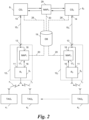
- Fig. 2 when the tag 4 1 communicates a message 7 1 according to the first protocol 10 1 to its "native" reader 5 1 , this first-protocol message 7 1 is present in the "correct" protocol 10 1 at an output 11 of the reader 5 1 .
- the reader 5 1 may be part or member of a lane controller 12 1 , which has an interface 13, which is connected to the output 11 of the reader 5 1 .
- the interface 13 of the lane controller 12 1 is in turn connected to an input 14 of the central station 8 1 responsible for the region 9 1 via a connection 15 1 .
- the reader 5 i is a "multi-protocol" reader meaning that it can receive messages 7 i according to at least two protocols 10 i , 10 i+1 as detailed below, for the central station 8 1 all messages conveyed via the connection 15 1 are present as first-protocol messages 7 1 , so that the central station 8 i needs to and can only parse messages according to its native protocol 10 1 .
- the multi-protocol reader 5 1 detects that a message was received according to the second protocol 10 2 by means of, e.g., the structure of the message 7 2 , and outputs it at an output 16 to the input of a mapping unit 17 1 .
- the mapping unit 17 1 has the task to generate a "new" first-protocol message 7 1 ' upon receiving such a second-protocol message 7 2 , which second protocol 10 2 is not "native" to the region 9 i in which the reader 5 1 is deployed.
- the mapping unit 17 i is connected to a correlation unit 19 via a connection 20.
- the correlation unit 19 can be embodied as a database DB as shown or alternatively as a computing unit executing a pre-defined algorithm. While the following example refers specifically to embodiments using the database DB, the computing unit can be used as the correlation unit 19 to the same effect.
- the mapping unit 17 1 After generating such a new first-protocol message 7 1 ' out of a second-protocol message 7 2 , the mapping unit 17 1 outputs the new first-protocol message 7 1 ' at an output 18 to the interface 13, from where it is fed to the input 14 of the central station 8 1 via the connection 15. In this way, between the interface 13 of the lane controller 12 1 and the input 14 of the central station 8 1 and within the central station 8 1 , only first-protocol messages 7 1 , 7 1 ' need to be transmitted and processed, regardless of the protocol 10 i of a message 7 i received by the reader 5 1 .
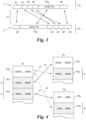
- Figs. 3 and 4 show an exemplary way of generating a new first-protocol message 7 1 ' by means of the mapping unit 17 1 .
- Fig. 3 depicts a predetermined mapping 21 which is used by the mapping unit 17 1 to generate a first-protocol message 7 1 ' out of a second-protocol message 7 2 .
- a header 22 is mapped from the beginning of the second-protocol message 7 2 to a new header 22' at the beginning of the new first-protocol message 7 1 '.
- the tag identification TID i is mapped from, e.g., the middle of the second-protocol message 7 2 to, for example, a second data field of the new first-protocol message 7 1 '.
- the second-protocol tag identification TID 2 is replaced by a new first-protocol tag identification TID 1 ' as will be described below by means of Fig. 4 in detail.
- a class data value 23, an HOV (high occupancy vehicle) data value 24, and a version data value 25 are mapped from the second-protocol message 7 2 to a new class data value 23', a new HOV data value 24', and a new version data value 25', e.g., from data fields before the tag identification TID 2 to data fields after the new tag identification TID 1 '.
- the last data field of the second-protocol message 7 2 is, in this case, a CRC (cyclic redundancy check) value 26 of the second-protocol message 7 2 that is validated before mapping.
- a new CRC value 26' is computed as part of generating the new first-protocol message 7 1 ' and added as a last data field to the new first-protocol message 7 1 '. In this way, a new first-protocol message 7 1 ' can be computed out of the second-protocol message 7 2 .
- Fig. 4 shows the content of the database DB used as the correlation unit 19, wherein unique tag identifications TID i of three protocols 10 1 , 10 2 , 10 3 are shown.
- "actual" tag identifications ranging from “00000” to “19999” are shown, which are assigned to tags 4 1 that operate according to the first protocol 10 1 .
- two reserved subsets s 2 , s 3 ranging from "20000” to "29999” and "30000” to "34999", respectively, of the unique tag identifiers TID 1 of the first protocol 10 1 are depicted.
- These reserved subsets s 2 , s 3 contain "virtual" tag identifications TID 1 ' that are not used for tags 4 i deployed in vehicles 3.
- unique tag identifications TID 2 of a second protocol 10 2 are shown, which are again split up into actual and virtual tag identifications TID 2 , TID 2 ' .
- unique tag identifications TID 3 of a third protocol 10 3 are shown split up into actual and virtual tag identifications TID 3 , TID 3 '.
- the algorithm could utilize any arithmetic function that allows a correlation between two tag identifications, e.g., TID i - 3 * TID i ' + 10000.
- the algorithm could also include if-statements to account for different lengths of tag identifications.
- each actual second-protocol tag identification TID 2 is correlated to one virtual first-protocol tag identification TID 1 '.
- the database DB can store such correlations 27 from the actual tag identifications TID 1 of the first protocol 10 1 to a respective subset s 1 of the second-protocol tag identifications TID 2 and to a respective subset s 1 of third-protocol tag identifications TID 3 (shown in dotted lines), and all other possible correlations (not shown).
- the mapping unit 17 1 generates a new first-protocol message 7 1 ' upon receiving a second-protocol message 7 2 from the reader 5 1 by means of three steps: Firstly, the second-protocol tag identification TID 2 is extracted from the second-protocol message 7 2 . Secondly, that first-protocol tag identification TID 1 that correlates to the extracted second-protocol tag identification TID 2 is retrieved from the database DB according to the correlation 27 in the database DB ( Fig. 4 ).
- said new first-protocol message 7 1 ' is generated by copying information from said second-protocol message 7 2 according to the predetermined mapping 21 between the second protocol 10 2 and the first protocol 10 1 while replacing the second-protocol tag identification TID 2 by the retrieved first-protocol tag identification TID 1 ( Fig. 3 ).
- the vehicles 3 can be identified by means of these messages, in particular by the actual or virtual tag identifications TID 1 , TID 1 ' therein. Identified vehicles 3 can then be tolled on the basis of their locations and/or used roads 2.
- the central station 8 i can detect whether a message 7 i , 7 i ' was mapped by means of the mapping unit 17 i by accessing the database DB via a connection 28. The central station 8 i then checks whether the tag identification TID i stored in a message 7 i , 7 i ' is present in a reserved subset s i as shown in Fig. 4 .
- the central station 8 i can forward this message 7 i ', which was apparently mapped by means of the mapping unit 17 i , to that central station 8 i (here: the "further" central station 8 2 ), which belongs to that reserved subset s i in which the tag identification TID i was found.
- this message can also be mapped back to the protocol 10 i in which it was originally received in the reader 5 i .
- a further mapping unit 29 is located downstream of the central station 8 i , e.g., interposed between the central station 8 1 and the further central station 8 2 .
- the further mapping unit 29 reconstructs the second-protocol message 7 2 as follows.
- the first-protocol tag identification TID 1 is extracted from said detected new first-protocol message 7 1 '.
- the further mapping unit 29 retrieves that second-protocol tag identification TID 2 that correlates (27) to the extracted first-protocol tag identification TID 1 from the database DB.
- said second-protocol message 7 2 is reconstructed by copying information from said new first-protocol message 7 1 ' according to the predetermined mapping 21 between the first protocol 10 1 and the second protocol 10 2 while replacing the first-protocol tag identification TID 1 by the retrieved second-protocol tag identification TID 2 .
- the further mapping unit 29 is connected to the correlation unit 19 via a connection 30.
- the further mapping unit 29 could also be arranged in the central station 8 i that forwards the message 7 1 ', or in that central station 8 1 that receives the message 7 1 '.
- the connection 28 and the connection 30 can be embodied as one.
- the correlation unit 19 could, instead of being a central correlation unit that is connected to each element, be embodied within each central station 8 i or mapping unit 17 i . In the example of Fig. 2 , this would mean that the correlation unit 19 would be present five times in the system, embodied in the mapping units 17 1 , 17 2 , 29 and in the central stations 8 1 , 8 2 .
- Such multiple correlation units 19 embodied as databases DB would then have substantially the same content. In case of any changes, such databases DB could be updated or synchronised, e.g., on a regular basis. If, on the other hand, computing units are used as such multiple correlation units 19, they would then use the same algorithm. In case of any changes, the algorithms of computing units could be updated or synchronised, e.g., on a regular basis.
Landscapes
- Engineering & Computer Science (AREA)
- Physics & Mathematics (AREA)
- General Physics & Mathematics (AREA)
- Computer Networks & Wireless Communication (AREA)
- Health & Medical Sciences (AREA)
- Toxicology (AREA)
- Business, Economics & Management (AREA)
- Signal Processing (AREA)
- Finance (AREA)
- General Health & Medical Sciences (AREA)
- Artificial Intelligence (AREA)
- Computer Vision & Pattern Recognition (AREA)
- Theoretical Computer Science (AREA)
- Electromagnetism (AREA)
- Devices For Checking Fares Or Tickets At Control Points (AREA)
- Mobile Radio Communication Systems (AREA)
Description
- The invention relates to a vehicle identification system comprising a central station and a roadside reader for wirelessly communicating with radio tags carried by vehicles, wherein a first tag is configured to wirelessly transmit messages according to a first protocol to the reader, each message comprising a unique first-protocol identification of the tag, and wherein a second tag is configured to wirelessly transmit messages according to a second protocol to the reader, each message comprising a unique second-protocol identification of the tag. The invention further relates to a method for identifying a vehicle in such a system.
- In road toll systems, vehicles are equipped with radio tags according to a wireless communication standard such as RFID, NFC, WiFi, Bluetooth, et cet. so that they can be wirelessly identified during their travel within the road toll system. Multiple radio roadside readers are distributed over the road toll system that can detect a passing tag. Depending on the radio technology used, this can be achieved in that the readers continuously emit polling messages and await responses from the tags. By means of such readers, the route travelled by vehicles in the road toll system can be tracked.
- Recently, there has been a need to ensure interoperability between multiple toll system operators tolling different geographical regions or even overlapping geographical regions. Each toll system operator distributes his own tags in the system, and the tags from different toll operators function according to different messaging protocols. Accordingly, tags may respond to readers with different message structures or may not respond at all when polled with the wrong protocol.
- The problem has been approached by introducing multi-protocol readers (see, e.g.,
US 2003/0109223 A1 ) that, for each protocol available, transmit a data stream to a back office of the road toll system. This approach has the disadvantage that the back office as well as
lane controllers and other parts of the system have to be physically upgraded to be able to handle messages of different protocols. Such system upgrades use a lot of resources and are very inefficient since back offices and lane controllers have to be upgraded with each toll system operator that is added to the system. - It is thus an aim of the invention to provide a vehicle identification system in which a plurality of toll system operators can function without an extensive overhaul of the road system.
- To achieve this goal, in a first aspect the invention provides for a vehicle identification system comprising a central station, a roadside reader for wirelessly communicating with radio tags carried by vehicles, a lane controller, a mapping unit connected to the reader, and a correlation unit connected to the mapping unit;
- the reader being configured to wirelessly receive messages according to a first protocol from a first tag affiliated to the central station and to wirelessly receive messages according to a second protocol from a second tag affiliated to another central station, wherein each first protocol message comprises a unique first-protocol identification of the transmitting first tag and wherein each second protocol message comprises a unique second-protocol identification of the transmitting second tag;
- the reader being part or member of the lane controller which has an interface connected to an input of the central station via a connection;
- the reader having a first output which is connected to the interface and a second output which is connected to the mapping unit;
- the mapping unit having an output which is also connected to the interface;
- wherein the correlation unit is configured to correlate second-protocol tag identifications to first-protocol tag identifications from a reserved subset of unique first-protocol tag identifications that are not used for tags deployed in vehicles and affiliated to the central station;
- wherein the reader is configured to selectively forward the wirelessly received first-protocol messages to the central station and the wirelessly received second-protocol messages to the mapping unit;
- wherein the mapping unit is configured to generate a new first-protocol message and forward this message to the central station upon receiving a second-protocol message from the reader by
- extracting the second-protocol tag identification from the second-protocol message,
- retrieving that unique first-protocol tag identification that correlates to the extracted second-protocol tag identification from the correlation unit,
- generating said new first-protocol message by copying information from said second-protocol message according to a predetermined mapping between the second protocol and the first protocol while replacing the second-protocol tag identification by the retrieved first-protocol tag identification, and
- forwarding the generated new first-protocol message to the central station;
- wherein the central station is configured to receive and store first-protocol messages from the reader as well as new first-protocol messages from the mapping unit and to identify a vehicle by means of the first-protocol tag identification therein.
- The advantage of such a system is that for each toll system operator joining the already present group of toll system operators, only the correlation unit has to be updated. There is no need to include additional interfaces in lane controllers or the central station, thus making the need for hardware upgrades obsolete. By reserving subsets of unique tag identifications, possible upgrades for additional toll system operators in the future can be handled in advance. Furthermore, the central station only needs a single interface to receive messages since all messages are received according to a single protocol.
- In the generation of the new first-protocol messages, the mapping is preferably unique such that it is clear that a mapping has occurred and so that it is reversible. This serves the purpose to re-create the original messages in later stages of the vehicle identification system.
- In a preferred embodiment, the central station is also connected to said correlation unit or is connected to a further correlation unit having the same content;
- wherein the central unit is configured to detect which received messages are new first-protocol messages by looking-up in the correlation unit or further correlation unit, respectively, if the tag identification of a received message is included in the reserved subset of first-protocol tag identifications;
- and wherein the central station is further configured to forward a new first-protocol message detected in this way to the other central station.
- By means of this, the central station can identify vehicles for which it is not responsible, e.g., for which no toll should be collected since they belong (are "subscribed") to a different toll system operator. The correlation unit thus serves two purposes, firstly to be able to map messages to a different protocol and secondly to identify messages that have been mapped. The dual-purpose correlation unit thus alleviates the distribution of messages to the different toll system operators.
- In another preferred embodiment, a further mapping unit is interposed between the central unit and the other central station and is configured to reconstruct the second-protocol message upon receiving said detected new first-protocol message from the central station by
- extracting the first-protocol tag identification from said detected new first-protocol message,
- retrieving that second-protocol tag identification that correlates to the extracted first-protocol tag identification from the correlation unit, and
- reconstructing said second-protocol message by copying information from said new first-protocol message according to a predetermined mapping between the first protocol and the second protocol while replacing the first-protocol tag identification by the retrieved second-protocol tag identification;
- By means of this, messages can be mapped back, i.e., reconstructed, to their original protocols. Receiving central stations thus do not recognize that messages have been transformed at all such that the inventive vehicle identification system is also compatible with legacy central stations and readers. This further enhances the backwards compatibility of the vehicle identification system.
- In one embodiment, the correlation unit is a database. Thereby, all correlations between tag identifications can be arbitrarily pre-defined and tag identifications can be added to the database on an individual basis.
- Alternatively, the correlation unit is a computing unit configured to execute a pre-defined algorithm. Thereby, correlations can be computed "on the fly" such that no extended storage is needed. Also, new tags can join the group of already existing tags if their tag identifications are comprised by the computing range of the algorithm.
- In a second aspect, the invention relates to a method for identifying a vehicle in a system comprising a central station, a roadside reader for wirelessly communicating with radio tags carried by vehicles, a lane controller, a mapping unit connected to the reader, and a correlation unit connected to the mapping unit, the reader being part or member of the lane controller which has an interface connected to an input of the central station via a connection, the reader having a first output which is connected to the interface and a second output which is connected to the mapping unit, and the mapping unit having an output which is also connected to the interface, the method comprising:
- providing a correlation in the correlation unit between second-protocol tag identifications and first-protocol tag identifications from a reserved subset of unique first-protocol tag identifications that are not used for tags deployed in vehicles and affiliated to the central station;
- wirelessly transmitting a message according to the first protocol from a first tag affiliated to the central station to the reader, the message comprising a unique first-protocol identification of the tag;
- wirelessly transmitting a message according to the second protocol from a second tag affiliated to another central station to the reader, the message comprising a unique second-protocol identification of the tag;
- selectively forwarding the first-protocol message from the reader to the central station and the second-protocol message from the reader to the mapping unit;
- in the mapping unit, generating and forwarding to the central station a new first-protocol message by
- extracting the second-protocol tag identification from the second-protocol message,
- retrieving that unique first-protocol tag identification that correlates to the extracted second-protocol tag identification from the correlation unit, and
- generating said new first-protocol message by copying information from said second-protocol message according to a predetermined mapping between the second protocol and the first protocol while replacing the second-protocol tag identification by the retrieved first-protocol tag identification, and
- forwarding the generated new first-protocol message to the central station;
- in the central station, receiving and storing the first-protocol message from the reader as well as the new first-protocol message from the mapping unit and identifying a vehicle by means of the first-protocol tag identification thereof.
- In a preferred embodiment the central station is also connected to said correlation unit or is connected to a further correlation unit having the same content, and the method comprises:
- in the central unit, detecting whether a received message is a new first-protocol message by looking-up in the correlation unit or further correlation unit, respectively, if the tag identification of the received message is included in the reserved subset of first-protocol tag identifications, and, if so,
- forwarding the new first-protocol message detected in this way to the other central station.
- In another preferred embodiment a further mapping unit is interposed between the central unit and the other central station, and the method comprises:
- in the further mapping unit, reconstructing the second-protocol message upon receiving said detected new first-protocol message from the central station by
- extracting the first-protocol tag identification from said detected new first-protocol message,
- retrieving that second-protocol tag identification that correlates to the extracted first-protocol tag identification from the correlation unit, and
- reconstructing said second-protocol message by copying information from said new first-protocol message according to a predetermined mapping between the first protocol and the second protocol while replacing the first-protocol tag identification by the retrieved second-protocol tag identification;
- and forwarding said reconstructed second-protocol message from the further mapping unit to the other central station.
- In one embodiment, the correlation unit is a database. Alternatively, the correlation unit is a computing unit executing a pre-defined algorithm.
- The advantages as set forth for the vehicle identification system analogously hold for the method for identifying a vehicle.
- The invention shall now be explained in more detail below on the basis of preferred exemplary embodiments thereof with reference to the accompanying drawings, in which:
-
Fig. 1 shows a road toll system in a schematic top view; -
Fig. 2 shows a block diagram of readers and central stations of the road toll system ofFig. 1 ; -
Fig. 3 shows a schematic mapping of a message according to a first protocol to a message according to a second protocol; and -
Fig. 4 shows a correlation of tag identifications between two protocols. -
Fig. 1 shows aroad toll system 1 withroads 2 on whichvehicles 3 travel. Thevehicles 3carry tags 4, for example in form of onboard units, by means of which thevehicles 3 can be identified in theroad toll system 1. The identification ofvehicles 3 in theroad toll system 1 can for example serve to impose toll oncertain roads 2. - To identify
vehicles 3 on theroads 2,roadside readers 5 are installed on certain sections of theroads 2. Theroadside readers 5 can be mounted ongantries 6, e.g., overhead gantries. Thereaders 5 and thetags 4 wirelessly communicate with each other according to a wireless communication standard such as RFID, NFC, WiFi, Bluetooth, or the like. To initiate a communication, thereaders 5 can, e.g., continuously emit polling messages, to which thetags 4 respond with a message 7, or vice versa. - The
readers 5 thus receive messages 7 and report these messages 7 back to one of several central stations 8i (i = 1, 2, 3, ...) used as "back offices", if applicable in combination with a timestamp, location and/or identification of therespective reader 5, et cet. - The messages 7 from the
tags 4 typically contain a unique identification of thetag 4, data relating to the type of thetag 4, and content of a memory of thetag 4 relating to, for example, previous reader passages, personal information of the vehicle owner, or information relating to thevehicle 3. - From
Fig. 1 it can further be seen that each central station 8i is responsible for a distinct geographical region 9i. Allreaders 5 in this geographical region 9i are connected to the central station 8i in which therespective reader 5 is deployed, i.e., eachreader 5 is assigned to one central station 8i. For this reason thereaders 5 will from now on be denoted asreaders 5i, wherein the index i indicates the affiliation to the central station 8i with the same index i. - In different embodiments, the geographical regions 9i are not mutually exclusive but can overlap such that mixed areas, in which
readers 5i from different groups i both report messages 7i back to different central stations 8i, are created. - The
tags 4 may be handed out to the customers of a toll operator operating a central station 8i for a specific geographical region 9i such that thesetags 4 are affiliated to the central station 8i with the index i, too. Thus, they are denoted astags 4i in the following. - To ensure a consistent communication within the region 9i of one toll operator, messages 7 between the
tags 4i,readers 5i, and the central station 8i of a single toll operator are performed according to a pre-defined protocol 10i. For this reason, messages 7 can also be denoted as messages 7i. - Messages 7i according to different protocols 10i here means that the messages 7i use a different structure of the data or information contained therein, as will be discussed later in detail with reference to
Fig. 3 . Exemplary protocols 10i used in theroad toll system 1 are E-ZPass TDM (Time Division Multiplexing), NIOP TDM, 6C by the Toll Operators Coalition, and the like. - Each group i of
tags 4i may use its own pool of tag identifications TIDi such that each tag identification TIDi is unique within each group, meaning that atag 4i can have a tag identification TIDi of, e.g., "12345", and this tag identification "12345" is only present once within a group i. However, this tag identification "12345" could be used in a different group i+1, for example, if this group i+1 uses a different protocol 10i+1. Furthermore, tag identifications TIDi can have different lengths between different groups i, i+1, for example group i can use 30-bit tag identifications TIDi while the group i+1 uses 40-bit tag identifications TIDi+1. - As
vehicles 3 roam freely on theroads 2 and thus between different geographical regions 9i, thereaders 5i and back offices 8i should to be configured to deal withtags 4i of different toll operators. An example of this is shown inFig. 2 , in which an exemplary interaction betweentags readers - In
Fig. 2 , when thetag 41 communicates a message 71 according to the first protocol 101 to its "native"reader 51, this first-protocol message 71 is present in the "correct" protocol 101 at anoutput 11 of thereader 51. Thereader 51 may be part or member of a lane controller 121, which has aninterface 13, which is connected to theoutput 11 of thereader 51. Theinterface 13 of the lane controller 121 is in turn connected to aninput 14 of the central station 81 responsible for the region 91 via a connection 151. While thereader 5i is a "multi-protocol" reader meaning that it can receive messages 7i according to at least two protocols 10i, 10i+1 as detailed below, for the central station 81 all messages conveyed via the connection 151 are present as first-protocol messages 71, so that the central station 8i needs to and can only parse messages according to its native protocol 101. - When a
tag 42 native to a different protocol group, here group i = 2, roams into the vicinity of areader 51 of the group i = 1, it transmits messages 72 according to the second protocol 102 to thereader 51. Themulti-protocol reader 51 detects that a message was received according to the second protocol 102 by means of, e.g., the structure of the message 72, and outputs it at anoutput 16 to the input of a mapping unit 171. The mapping unit 171 has the task to generate a "new" first-protocol message 71' upon receiving such a second-protocol message 72, which second protocol 102 is not "native" to the region 9i in which thereader 51 is deployed. For this purpose, the mapping unit 17i is connected to acorrelation unit 19 via aconnection 20. Thecorrelation unit 19 can be embodied as a database DB as shown or alternatively as a computing unit executing a pre-defined algorithm. While the following example refers specifically to embodiments using the database DB, the computing unit can be used as thecorrelation unit 19 to the same effect. - After generating such a new first-protocol message 71' out of a second-protocol message 72, the mapping unit 171 outputs the new first-protocol message 71' at an
output 18 to theinterface 13, from where it is fed to theinput 14 of the central station 81 via the connection 15. In this way, between theinterface 13 of the lane controller 121 and theinput 14 of the central station 81 and within the central station 81, only first-protocol messages 71, 71' need to be transmitted and processed, regardless of the protocol 10i of a message 7i received by thereader 51. - In the following,
Figs. 3 and 4 show an exemplary way of generating a new first-protocol message 71' by means of the mapping unit 171.Fig. 3 depicts apredetermined mapping 21 which is used by the mapping unit 171 to generate a first-protocol message 71' out of a second-protocol message 72. As can be seen, aheader 22 is mapped from the beginning of the second-protocol message 72 to a new header 22' at the beginning of the new first-protocol message 71'. The tag identification TIDi is mapped from, e.g., the middle of the second-protocol message 72 to, for example, a second data field of the new first-protocol message 71'. Concurrently, the second-protocol tag identification TID2 is replaced by a new first-protocol tag identification TID1' as will be described below by means ofFig. 4 in detail. Aclass data value 23, an HOV (high occupancy vehicle)data value 24, and aversion data value 25 are mapped from the second-protocol message 72 to a new class data value 23', a new HOV data value 24', and a new version data value 25', e.g., from data fields before the tag identification TID2 to data fields after the new tag identification TID1'. The last data field of the second-protocol message 72 is, in this case, a CRC (cyclic redundancy check)value 26 of the second-protocol message 72 that is validated before mapping. A new CRC value 26' is computed as part of generating the new first-protocol message 71' and added as a last data field to the new first-protocol message 71'. In this way, a new first-protocol message 71' can be computed out of the second-protocol message 72. - As mentioned above,
Fig. 4 shows the content of the database DB used as thecorrelation unit 19, wherein unique tag identifications TIDi of three protocols 101, 102, 103 are shown. On the left, "actual" tag identifications ranging from "00000" to "19999" are shown, which are assigned totags 41 that operate according to the first protocol 101. Additionally, two reserved subsets s2, s3 ranging from "20000" to "29999" and "30000" to "34999", respectively, of the unique tag identifiers TID1 of the first protocol 101 are depicted. These reserved subsets s2, s3 contain "virtual" tag identifications TID1' that are not used fortags 4i deployed invehicles 3. - Similarly, on the top right of
Fig. 4 , unique tag identifications TID2 of a second protocol 102 are shown, which are again split up into actual and virtual tag identifications TID2, TID2' . On the bottom right ofFig. 4 , unique tag identifications TID3 of a third protocol 103 are shown split up into actual and virtual tag identifications TID3, TID3'. - If a computing unit executing a pre-defined algorithm is used as the
correlation unit 19, the algorithm could utilize any arithmetic function that allows a correlation between two tag identifications, e.g., TIDi - 3 * TIDi' + 10000. The algorithm could also include if-statements to account for different lengths of tag identifications. - To implement the replacement of a tag identification TID2 in a
mapping 21 as was explained above with respect toFig. 3 , the actual tag identifications TID2 of the second protocol 102 are correlated, seearrows 27, to the second subset s2 of the first-protocol tag identifications TID1, i.e., each actual second-protocol tag identification TID2 is correlated to one virtual first-protocol tag identification TID1'. - For the purpose of replacing a third-protocol tag identification TID3, analogously the actual tag identifications TID3 of the third protocol 103 are correlated to the third subset s3 of the first-protocol tag identifications TID1. From the
exemplary correlation 27 between the first protocol 101 and the third protocol 103 it can also be seen that a possible change in (bit-) length of the tag identifications TIDi can be overcome this way. - Furthermore, the database DB can store
such correlations 27 from the actual tag identifications TID1 of the first protocol 101 to a respective subset s1 of the second-protocol tag identifications TID2 and to a respective subset s1 of third-protocol tag identifications TID3 (shown in dotted lines), and all other possible correlations (not shown). - Coming back to
Fig. 2 , it can thus be summarized that the mapping unit 171 generates a new first-protocol message 71' upon receiving a second-protocol message 72 from thereader 51 by means of three steps: Firstly, the second-protocol tag identification TID2 is extracted from the second-protocol message 72. Secondly, that first-protocol tag identification TID1 that correlates to the extracted second-protocol tag identification TID2 is retrieved from the database DB according to thecorrelation 27 in the database DB (Fig. 4 ). Thirdly, said new first-protocol message 71' is generated by copying information from said second-protocol message 72 according to thepredetermined mapping 21 between the second protocol 102 and the first protocol 101 while replacing the second-protocol tag identification TID2 by the retrieved first-protocol tag identification TID1 (Fig. 3 ). - Once messages 71, 71' have been received in the central station 81, the
vehicles 3 can be identified by means of these messages, in particular by the actual or virtual tag identifications TID1, TID1' therein.Identified vehicles 3 can then be tolled on the basis of their locations and/or usedroads 2. - In most cases,
vehicles 3 that are equipped with atag 4i from a different toll operator should, however, only be tolled by the central station 8i of this agency. To this end, the central station 8i can detect whether a message 7i, 7i' was mapped by means of the mapping unit 17i by accessing the database DB via aconnection 28. The central station 8i then checks whether the tag identification TIDi stored in a message 7i, 7i' is present in a reserved subset si as shown inFig. 4 . If this is the case, the central station 8i can forward this message 7i', which was apparently mapped by means of the mapping unit 17i, to that central station 8i (here: the "further" central station 82), which belongs to that reserved subset si in which the tag identification TIDi was found. - As can be seen from
Fig. 2 , instead of just forwarding a message 7i, 7i', this message can also be mapped back to the protocol 10i in which it was originally received in thereader 5i. For this purpose, afurther mapping unit 29 is located downstream of the central station 8i, e.g., interposed between the central station 81 and the further central station 82. Thefurther mapping unit 29 reconstructs the second-protocol message 72 as follows. - Firstly, the first-protocol tag identification TID1 is extracted from said detected new first-protocol message 71'. Secondly, the
further mapping unit 29 retrieves that second-protocol tag identification TID2 that correlates (27) to the extracted first-protocol tag identification TID1 from the database DB. Thirdly, said second-protocol message 72 is reconstructed by copying information from said new first-protocol message 71' according to thepredetermined mapping 21 between the first protocol 101 and the second protocol 102 while replacing the first-protocol tag identification TID1 by the retrieved second-protocol tag identification TID2. - For the purpose of mapping back the extracted tag identification TIDi, the
further mapping unit 29 is connected to thecorrelation unit 19 via aconnection 30. However, thefurther mapping unit 29 could also be arranged in the central station 8i that forwards the message 71', or in that central station 81 that receives the message 71'. In this case, theconnection 28 and theconnection 30 can be embodied as one. - The
correlation unit 19 could, instead of being a central correlation unit that is connected to each element, be embodied within each central station 8i or mapping unit 17i. In the example ofFig. 2 , this would mean that thecorrelation unit 19 would be present five times in the system, embodied in themapping units 171, 172, 29 and in the central stations 81, 82. Suchmultiple correlation units 19 embodied as databases DB would then have substantially the same content. In case of any changes, such databases DB could be updated or synchronised, e.g., on a regular basis. If, on the other hand, computing units are used as suchmultiple correlation units 19, they would then use the same algorithm. In case of any changes, the algorithms of computing units could be updated or synchronised, e.g., on a regular basis. - The invention is not restricted to the specific embodiments described in detail herein, but encompasses all variants, combinations and modifications thereof that fall within the framework of the appended claims.
Claims (10)
- Vehicle identification system comprising a central station (81), a roadside reader (51) for wirelessly communicating with radio tags (41, 42) carried by vehicles (3), a lane controller (121), a mapping unit (171) connected to the reader (51), and a correlation unit (19) connected to the mapping unit (171);the reader (51) being configured to wirelessly receive messages according to a first protocol (101) from a first tag (41) affiliated to the central station (81) and to wirelessly receive messages according to a second protocol (102) from a second tag (42) affiliated to another central station (82), wherein each first protocol message (71) comprises a unique first-protocol identification (TID1) of the transmitting first tag (41) and wherein each second protocol message (72) comprises a unique second-protocol identification (TID2) of the transmitting second tag (42);the reader (51) being part or member of the lane controller (121) which has an interface (13) connected to an input (14) of the central station (81) via a connection (151);the reader (51) having a first output (11) which is connected to the interface (13) and a second output (16) which is connected to the mapping unit (171);the mapping unit (171) having an output (18) which is also connected to the interface (13);wherein the correlation unit (19) is configured to correlate second-protocol tag identifications (TID2) to first-protocol tag identifications (TID1') from a reserved subset (s2) of unique first-protocol tag identifications (TID1) that are not used for tags (4i) deployed in vehicles (3) and affiliated to the central station (81);wherein the reader (51) is configured to selectively forward the wirelessly received first-protocol messages (71) to the central station (81) and the wirelessly received second-protocol messages (72) to the mapping unit (171);wherein the mapping unit (171) is configured to generate a new first-protocol message (71') and forward this message (71') to the central station (81) upon receiving a second-protocol message (72) from the reader (51) by- extracting the second-protocol tag identification (TID2) from the second-protocol message (72),- retrieving that unique first-protocol tag identification (TID1') that correlates to the extracted second-protocol tag identification (TID2) from the correlation unit (19),- generating said new first-protocol message (71') by copying information from said second-protocol message (72) according to a predetermined mapping (21) between the second protocol (102) and the first protocol (101) while replacing the second-protocol tag identification (TID2) by the retrieved first-protocol tag identification (TID1'), and- forwarding the generated new first-protocol message (71') to the central station (81);wherein the central station (81) is configured to receive and store first-protocol messages (71) from the reader (51) as well as new first-protocol messages (71') from the mapping unit (171) and to identify a vehicle (3) by means of the first-protocol tag identification therein (TID1, TID1').
- Vehicle identification system according to claim 1, wherein the central station (81) is also connected to said correlation unit (19) or is connected to a further correlation unit having the same content,and wherein the central station (81) is configured to detect which received messages (71, 71') are new first-protocol messages (71') by looking-up in the correlation unit (19) or further correlation unit, respectively, if the tag identification (TID1, TID1') of a received message (71, 71') is included in the reserved subset (s2) of first-protocol tag identifications (TID1),and is further configured to forward a new first-protocol message (71') detected in this way to the other central station (82).
- Vehicle identification system according to claim 2, wherein a further mapping unit (29) is interposed between the central unit (81) and the other central station (82) and is configured to reconstruct the second-protocol message (72) upon receiving said detected new first-protocol message (71') from the central station (81) by- extracting the first-protocol tag identification (TID1) from said detected new first-protocol message (71'),- retrieving that second-protocol tag identification (TID2) that correlates to the extracted first-protocol tag identification (TID1') from the correlation unit (19), and- reconstructing said second-protocol message (72) by copying information from said new first-protocol message (71') according to a predetermined mapping (21) between the first protocol (101) and the second protocol (102) while replacing the first-protocol tag identification (TID1') by the retrieved second-protocol tag identification (TID2);and wherein the further mapping unit is further configured to forward said reconstructed second-protocol message (72) to the other central station (82).
- Vehicle identification system according to any one of the claims 1 to 3, wherein the correlation unit (19) is a database (DB).
- Vehicle identification system according to any one of the claims 1 to 3, wherein the correlation unit (19) is a computing unit configured to execute a pre-defined algorithm.
- Method for identifying a vehicle in a system comprising a central station (81), a roadside reader (51) for wirelessly communicating with radio tags (41, 42) carried by vehicles (3), a lane controller (121), a mapping unit (171) connected to the reader (51), and a correlation unit (19) connected to the mapping unit (171), the reader (51) being part or member of the lane controller (121) which has an interface (13) connected to an input (14) of the central station (81) via a connection (151), the reader (51) having a first output (11) which is connected to the interface (13) and a second output (16) which is connected to the mapping unit (171), and the mapping unit (171) having an output (18) which is also connected to the interface (13), the method comprising:providing a correlation in the correlation unit (19) between second-protocol tag identifications (TID2) and first-protocol tag identifications (TID1') from a reserved subset (s2) of unique first-protocol tag identifications (TID1) that are not used for tags (4i) deployed in vehicles (3) and affiliated to the central station (81);wirelessly transmitting a message (71) according to the first protocol (101) from a first tag (41) affiliated to the central station (81) to the reader (51), the message (71) comprising a unique first-protocol identification (TID1) of the tag (41);wirelessly transmitting a message (72) according to the second protocol (102) from a second tag (42) affiliated to another central station (82) to the reader (51), the message (72) comprising a unique second-protocol identification (TID2) of the tag (42) ;selectively forwarding the first-protocol message (71) from the reader (51) to the central station (81) and the second-protocol message (72) from the reader (51) to the mapping unit (171);in the mapping unit (171), generating and forwarding to the central station (81) a new first-protocol message (71') by- extracting the second-protocol tag identification (TID2) from the second-protocol message (72),- retrieving that unique first-protocol tag identification (TID1) that correlates to the extracted second-protocol tag identification (TID2) from the correlation unit (19), and- generating said new first-protocol message (71') by copying information from said second-protocol message (72) according to a predetermined mapping (21) between the second protocol (102) and the first protocol (71) while replacing the second-protocol tag identification (TID2) by the retrieved first-protocol tag identification (TID1'), and- forwarding the generated new first-protocol message (71') to the central station (81);in the central station (81), receiving and storing the first-protocol message (71) from the reader (51) as well as the new first-protocol message (71') from the mapping unit (171) and identifying a vehicle (3) by means of the first-protocol tag identification (TID1, TID1') thereof.
- Method according to claim 6, wherein the central station (81) is also connected to said correlation unit (19) or is connected to a further correlation unit having the same content, the method comprising:in the central unit (81), detecting whether a received message (71, 71') is a new first-protocol message (71') by looking-up in the correlation unit (19) or further correlation unit, respectively, if the tag identification (TID1) of the received message (71, 71') is included in the reserved subset (s2) of first-protocol tag identifications (TID1), and, if so,forwarding the new first-protocol message (71') detected in this way to the other central station (82).
- Method according to claim 7, wherein a further mapping unit (29) is interposed between the central unit (81) and the other central station (82), the method comprising:in the further mapping unit (29), reconstructing the second-protocol message (72) upon receiving said detected new first-protocol message (71') from the central station (81) by- extracting the first-protocol tag identification (TID1') from said detected new first-protocol message (71'),- retrieving that second-protocol tag identification (TID2) that correlates to the extracted first-protocol tag identification (TID1') from the correlation unit (19), and- reconstructing said second-protocol message (72) by copying information from said new first-protocol message (71') according to a predetermined mapping (21) between the first protocol (101) and the second protocol (102) while replacing the first-protocol tag identification (TID1') by the retrieved second-protocol tag identification (TID2);and forwarding said reconstructed second-protocol message (72) from the further mapping unit (29) to the other central station (82).
- Method according to any one of the claims 6 to 8, wherein the correlation unit (19) is a database (DB).
- Method according to any one of the claims 6 to 8, wherein the correlation unit is a computing unit executing a pre-defined algorithm.
Priority Applications (4)
| Application Number | Priority Date | Filing Date | Title |
|---|---|---|---|
| EP17165144.1A EP3385918B1 (en) | 2017-04-06 | 2017-04-06 | Vehicle identification system and method |
| ES17165144T ES2987920T3 (en) | 2017-04-06 | 2017-04-06 | Vehicle identification system and procedure |
| CA3000384A CA3000384C (en) | 2017-04-06 | 2018-04-05 | Vehicle identification system and method |
| US15/946,363 US10157540B2 (en) | 2017-04-06 | 2018-04-05 | Vehicle identification system and method |
Applications Claiming Priority (1)
| Application Number | Priority Date | Filing Date | Title |
|---|---|---|---|
| EP17165144.1A EP3385918B1 (en) | 2017-04-06 | 2017-04-06 | Vehicle identification system and method |
Publications (3)
| Publication Number | Publication Date |
|---|---|
| EP3385918A1 EP3385918A1 (en) | 2018-10-10 |
| EP3385918B1 true EP3385918B1 (en) | 2024-03-06 |
| EP3385918C0 EP3385918C0 (en) | 2024-03-06 |
Family
ID=58709198
Family Applications (1)
| Application Number | Title | Priority Date | Filing Date |
|---|---|---|---|
| EP17165144.1A Active EP3385918B1 (en) | 2017-04-06 | 2017-04-06 | Vehicle identification system and method |
Country Status (4)
| Country | Link |
|---|---|
| US (1) | US10157540B2 (en) |
| EP (1) | EP3385918B1 (en) |
| CA (1) | CA3000384C (en) |
| ES (1) | ES2987920T3 (en) |
Families Citing this family (1)
| Publication number | Priority date | Publication date | Assignee | Title |
|---|---|---|---|---|
| CN110349279B (en) * | 2019-05-22 | 2021-06-11 | 蔡欧 | Vehicle-mounted electronic tag |
Family Cites Families (23)
| Publication number | Priority date | Publication date | Assignee | Title |
|---|---|---|---|---|
| US4808803A (en) * | 1987-08-24 | 1989-02-28 | Figgi International, Inc. | Security system |
| FI107501B (en) * | 1997-01-31 | 2001-08-15 | Nokia Mobile Phones Ltd | Procedure for allocating user identification |
| US6452915B1 (en) * | 1998-07-10 | 2002-09-17 | Malibu Networks, Inc. | IP-flow classification in a wireless point to multi-point (PTMP) transmission system |
| DE10104499A1 (en) * | 2001-01-31 | 2002-08-14 | Daimler Chrysler Ag | Road tolling system |
| JP3855747B2 (en) * | 2001-11-26 | 2006-12-13 | 株式会社デンソー | Fixed station communication device, automatic fee collection system, automatic fee collection communication method |
| US7512236B1 (en) * | 2004-08-06 | 2009-03-31 | Mark Iv Industries Corporation | System and method for secure mobile commerce |
| US7966012B2 (en) * | 2004-09-09 | 2011-06-21 | Parkervision, Inc. | Wireless protocol converter |
| EP1813085B1 (en) * | 2004-11-19 | 2009-09-23 | Sensormatic Electronics Corporation | Technique and hardware for communicating with backscatter radio frequency identification readers |
| US8322608B2 (en) * | 2005-08-15 | 2012-12-04 | Assa Abloy Ab | Using promiscuous and non-promiscuous data to verify card and reader identity |
| US8967476B2 (en) * | 2005-09-09 | 2015-03-03 | Assa Abloy Ab | Synchronization techniques in multi-technology/multi-frequency RFID reader arrays |
| US8917178B2 (en) * | 2006-06-09 | 2014-12-23 | Dominic M. Kotab | RFID system and method for storing information related to a vehicle or an owner of the vehicle |
| US9426224B1 (en) * | 2015-02-09 | 2016-08-23 | General Electric Company | Protocol conversion system and method for a vehicle system |
| US8751092B2 (en) * | 2011-01-13 | 2014-06-10 | Continental Automotive Systems, Inc. | Protocol protection |
| US9097614B2 (en) * | 2012-01-18 | 2015-08-04 | Xerox Corporation | Vehicle emissions testing and toll collection system |
| US10019706B2 (en) * | 2012-11-27 | 2018-07-10 | Geotoll, Inc. | Method and apparatus for providing a toll service and flexible toll device |
| US9635146B2 (en) * | 2014-06-19 | 2017-04-25 | Cavium, Inc. | Method of using bit vectors to allow expansion and collapse of header layers within packets for enabling flexible modifications and an apparatus thereof |
| US9429436B2 (en) * | 2015-01-13 | 2016-08-30 | Toyota Motor Engineering & Manufacturing North America, Inc. | Estimated time of arrival for vehicle navigation |
| CN108136963B (en) * | 2015-10-22 | 2021-04-27 | 金泰克斯公司 | Integrated vehicle communication system and method |
| US9786109B2 (en) * | 2015-12-17 | 2017-10-10 | Nxp B.V. | Use of a biphase code matched filter to receive protocols with code violations |
| US20180012196A1 (en) * | 2016-07-07 | 2018-01-11 | NextEv USA, Inc. | Vehicle maintenance manager |
| US20180025551A1 (en) * | 2016-07-21 | 2018-01-25 | Highway Toll Administration, Llc | Vehicle toll usage tracking system and method |
| US10078950B2 (en) * | 2016-07-25 | 2018-09-18 | Symbol Technologies, Llc | Remotely configurable location tracking tags |
| US9922473B1 (en) * | 2017-01-23 | 2018-03-20 | UScontracting, Inc. | Systems and methods for location-based automated authentication |
-
2017
- 2017-04-06 ES ES17165144T patent/ES2987920T3/en active Active
- 2017-04-06 EP EP17165144.1A patent/EP3385918B1/en active Active
-
2018
- 2018-04-05 CA CA3000384A patent/CA3000384C/en active Active
- 2018-04-05 US US15/946,363 patent/US10157540B2/en active Active
Also Published As
| Publication number | Publication date |
|---|---|
| EP3385918A1 (en) | 2018-10-10 |
| US20180293882A1 (en) | 2018-10-11 |
| US10157540B2 (en) | 2018-12-18 |
| CA3000384A1 (en) | 2018-10-06 |
| CA3000384C (en) | 2026-02-24 |
| ES2987920T3 (en) | 2024-11-18 |
| EP3385918C0 (en) | 2024-03-06 |
Similar Documents
| Publication | Publication Date | Title |
|---|---|---|
| US11438742B2 (en) | Method and apparatus for vehicle-to-vehicle message service | |
| CN106672020B (en) | Front truck recognition methods, Vehicle Controller and train based on object controller | |
| CN112199266B (en) | Log transmission method and system for vehicle-mounted machine system, vehicle and storage medium | |
| CN102779421A (en) | Method and system for updating road condition information in real time based on vehicle tablet terminal | |
| KR20150087873A (en) | An Internet-of-Things system for public transportation service, and the method thereof | |
| CN109788515B (en) | A data collaboration method, MEC device and server | |
| CN104933544A (en) | Automatic processing tracking method and system for express delivery | |
| US10157540B2 (en) | Vehicle identification system and method | |
| JP4821498B2 (en) | Operation management system and platooning device | |
| CN112801354A (en) | Route planning method and device | |
| KR101651752B1 (en) | Communication based train control system for processing automatic train registration and method thereof | |
| CN111212133A (en) | Vehicle remote interaction event tracking system | |
| ZA202209618B (en) | Communication device, program, communication method, information processing method, information processing device, and communication system | |
| CN102426800A (en) | Wireless vehicle traffic guidance system and method | |
| KR101307242B1 (en) | Method and device for using item order in list as identifier | |
| US20240177597A1 (en) | Interaction method and interaction apparatus | |
| US20240420517A1 (en) | Method for storing and evaluating status information recorded within a v2x network | |
| CN115320673B (en) | Train operation control method, device, equipment and storage medium | |
| CN105760977A (en) | Certificate production method and system | |
| CN103886771A (en) | Traveling management method and system for school bus | |
| EP3082099A1 (en) | Intermodal travel service system for communicating with a number of different travel and traffic service providers | |
| CN105321211A (en) | Real-time train capacity query method and system | |
| WO2021130024A1 (en) | Itinerary generation apparatus, itinerary generation system, itinerary generation method and computer program product | |
| KR101283358B1 (en) | Method and device for using item order in list as identifier | |
| CN116255995B (en) | Vehicle navigation control methods, devices and vehicles |
Legal Events
| Date | Code | Title | Description |
|---|---|---|---|
| PUAI | Public reference made under article 153(3) epc to a published international application that has entered the european phase |
Free format text: ORIGINAL CODE: 0009012 |
|
| STAA | Information on the status of an ep patent application or granted ep patent |
Free format text: STATUS: THE APPLICATION HAS BEEN PUBLISHED |
|
| AK | Designated contracting states |
Kind code of ref document: A1 Designated state(s): AL AT BE BG CH CY CZ DE DK EE ES FI FR GB GR HR HU IE IS IT LI LT LU LV MC MK MT NL NO PL PT RO RS SE SI SK SM TR |
|
| AX | Request for extension of the european patent |
Extension state: BA ME |
|
| STAA | Information on the status of an ep patent application or granted ep patent |
Free format text: STATUS: REQUEST FOR EXAMINATION WAS MADE |
|
| 17P | Request for examination filed |
Effective date: 20181010 |
|
| RBV | Designated contracting states (corrected) |
Designated state(s): AL AT BE BG CH CY CZ DE DK EE ES FI FR GB GR HR HU IE IS IT LI LT LU LV MC MK MT NL NO PL PT RO RS SE SI SK SM TR |
|
| STAA | Information on the status of an ep patent application or granted ep patent |
Free format text: STATUS: EXAMINATION IS IN PROGRESS |
|
| 17Q | First examination report despatched |
Effective date: 20200909 |
|
| GRAP | Despatch of communication of intention to grant a patent |
Free format text: ORIGINAL CODE: EPIDOSNIGR1 |
|
| STAA | Information on the status of an ep patent application or granted ep patent |
Free format text: STATUS: GRANT OF PATENT IS INTENDED |
|
| RIC1 | Information provided on ipc code assigned before grant |
Ipc: H04W 4/44 20180101ALI20230925BHEP Ipc: G08G 1/017 20060101ALI20230925BHEP Ipc: G07B 15/06 20110101AFI20230925BHEP |
|
| INTG | Intention to grant announced |
Effective date: 20231016 |
|
| GRAS | Grant fee paid |
Free format text: ORIGINAL CODE: EPIDOSNIGR3 |
|
| GRAA | (expected) grant |
Free format text: ORIGINAL CODE: 0009210 |
|
| STAA | Information on the status of an ep patent application or granted ep patent |
Free format text: STATUS: THE PATENT HAS BEEN GRANTED |
|
| AK | Designated contracting states |
Kind code of ref document: B1 Designated state(s): AL AT BE BG CH CY CZ DE DK EE ES FI FR GB GR HR HU IE IS IT LI LT LU LV MC MK MT NL NO PL PT RO RS SE SI SK SM TR |
|
| REG | Reference to a national code |
Ref country code: GB Ref legal event code: FG4D |
|
| REG | Reference to a national code |
Ref country code: CH Ref legal event code: EP |
|
| REG | Reference to a national code |
Ref country code: DE Ref legal event code: R096 Ref document number: 602017079713 Country of ref document: DE |
|
| REG | Reference to a national code |
Ref country code: IE Ref legal event code: FG4D |
|
| U01 | Request for unitary effect filed |
Effective date: 20240320 |
|
| U07 | Unitary effect registered |
Designated state(s): AT BE BG DE DK EE FI FR IT LT LU LV MT NL PT SE SI Effective date: 20240328 |
|
| U20 | Renewal fee for the european patent with unitary effect paid |
Year of fee payment: 8 Effective date: 20240527 |
|
| PG25 | Lapsed in a contracting state [announced via postgrant information from national office to epo] |
Ref country code: GR Free format text: LAPSE BECAUSE OF FAILURE TO SUBMIT A TRANSLATION OF THE DESCRIPTION OR TO PAY THE FEE WITHIN THE PRESCRIBED TIME-LIMIT Effective date: 20240607 |
|
| PG25 | Lapsed in a contracting state [announced via postgrant information from national office to epo] |
Ref country code: RS Free format text: LAPSE BECAUSE OF FAILURE TO SUBMIT A TRANSLATION OF THE DESCRIPTION OR TO PAY THE FEE WITHIN THE PRESCRIBED TIME-LIMIT Effective date: 20240606 Ref country code: HR Free format text: LAPSE BECAUSE OF FAILURE TO SUBMIT A TRANSLATION OF THE DESCRIPTION OR TO PAY THE FEE WITHIN THE PRESCRIBED TIME-LIMIT Effective date: 20240306 |
|
| PG25 | Lapsed in a contracting state [announced via postgrant information from national office to epo] |
Ref country code: RS Free format text: LAPSE BECAUSE OF FAILURE TO SUBMIT A TRANSLATION OF THE DESCRIPTION OR TO PAY THE FEE WITHIN THE PRESCRIBED TIME-LIMIT Effective date: 20240606 Ref country code: NO Free format text: LAPSE BECAUSE OF FAILURE TO SUBMIT A TRANSLATION OF THE DESCRIPTION OR TO PAY THE FEE WITHIN THE PRESCRIBED TIME-LIMIT Effective date: 20240606 Ref country code: HR Free format text: LAPSE BECAUSE OF FAILURE TO SUBMIT A TRANSLATION OF THE DESCRIPTION OR TO PAY THE FEE WITHIN THE PRESCRIBED TIME-LIMIT Effective date: 20240306 Ref country code: GR Free format text: LAPSE BECAUSE OF FAILURE TO SUBMIT A TRANSLATION OF THE DESCRIPTION OR TO PAY THE FEE WITHIN THE PRESCRIBED TIME-LIMIT Effective date: 20240607 |
|
| PG25 | Lapsed in a contracting state [announced via postgrant information from national office to epo] |
Ref country code: IS Free format text: LAPSE BECAUSE OF FAILURE TO SUBMIT A TRANSLATION OF THE DESCRIPTION OR TO PAY THE FEE WITHIN THE PRESCRIBED TIME-LIMIT Effective date: 20240706 |
|
| PG25 | Lapsed in a contracting state [announced via postgrant information from national office to epo] |
Ref country code: SM Free format text: LAPSE BECAUSE OF FAILURE TO SUBMIT A TRANSLATION OF THE DESCRIPTION OR TO PAY THE FEE WITHIN THE PRESCRIBED TIME-LIMIT Effective date: 20240306 |
|
| PG25 | Lapsed in a contracting state [announced via postgrant information from national office to epo] |
Ref country code: CZ Free format text: LAPSE BECAUSE OF FAILURE TO SUBMIT A TRANSLATION OF THE DESCRIPTION OR TO PAY THE FEE WITHIN THE PRESCRIBED TIME-LIMIT Effective date: 20240306 |
|
| PG25 | Lapsed in a contracting state [announced via postgrant information from national office to epo] |
Ref country code: PL Free format text: LAPSE BECAUSE OF FAILURE TO SUBMIT A TRANSLATION OF THE DESCRIPTION OR TO PAY THE FEE WITHIN THE PRESCRIBED TIME-LIMIT Effective date: 20240306 |
|
| PG25 | Lapsed in a contracting state [announced via postgrant information from national office to epo] |
Ref country code: SK Free format text: LAPSE BECAUSE OF FAILURE TO SUBMIT A TRANSLATION OF THE DESCRIPTION OR TO PAY THE FEE WITHIN THE PRESCRIBED TIME-LIMIT Effective date: 20240306 |
|
| PG25 | Lapsed in a contracting state [announced via postgrant information from national office to epo] |
Ref country code: SM Free format text: LAPSE BECAUSE OF FAILURE TO SUBMIT A TRANSLATION OF THE DESCRIPTION OR TO PAY THE FEE WITHIN THE PRESCRIBED TIME-LIMIT Effective date: 20240306 Ref country code: SK Free format text: LAPSE BECAUSE OF FAILURE TO SUBMIT A TRANSLATION OF THE DESCRIPTION OR TO PAY THE FEE WITHIN THE PRESCRIBED TIME-LIMIT Effective date: 20240306 Ref country code: RO Free format text: LAPSE BECAUSE OF FAILURE TO SUBMIT A TRANSLATION OF THE DESCRIPTION OR TO PAY THE FEE WITHIN THE PRESCRIBED TIME-LIMIT Effective date: 20240306 Ref country code: PL Free format text: LAPSE BECAUSE OF FAILURE TO SUBMIT A TRANSLATION OF THE DESCRIPTION OR TO PAY THE FEE WITHIN THE PRESCRIBED TIME-LIMIT Effective date: 20240306 Ref country code: IS Free format text: LAPSE BECAUSE OF FAILURE TO SUBMIT A TRANSLATION OF THE DESCRIPTION OR TO PAY THE FEE WITHIN THE PRESCRIBED TIME-LIMIT Effective date: 20240706 Ref country code: CZ Free format text: LAPSE BECAUSE OF FAILURE TO SUBMIT A TRANSLATION OF THE DESCRIPTION OR TO PAY THE FEE WITHIN THE PRESCRIBED TIME-LIMIT Effective date: 20240306 |
|
| REG | Reference to a national code |
Ref country code: ES Ref legal event code: FG2A Ref document number: 2987920 Country of ref document: ES Kind code of ref document: T3 Effective date: 20241118 |
|
| REG | Reference to a national code |
Ref country code: CH Ref legal event code: PL |
|
| REG | Reference to a national code |
Ref country code: DE Ref legal event code: R097 Ref document number: 602017079713 Country of ref document: DE |
|
| PG25 | Lapsed in a contracting state [announced via postgrant information from national office to epo] |
Ref country code: MC Free format text: LAPSE BECAUSE OF FAILURE TO SUBMIT A TRANSLATION OF THE DESCRIPTION OR TO PAY THE FEE WITHIN THE PRESCRIBED TIME-LIMIT Effective date: 20240306 |
|
| PLBE | No opposition filed within time limit |
Free format text: ORIGINAL CODE: 0009261 |
|
| STAA | Information on the status of an ep patent application or granted ep patent |
Free format text: STATUS: NO OPPOSITION FILED WITHIN TIME LIMIT |
|
| PG25 | Lapsed in a contracting state [announced via postgrant information from national office to epo] |
Ref country code: MC Free format text: LAPSE BECAUSE OF FAILURE TO SUBMIT A TRANSLATION OF THE DESCRIPTION OR TO PAY THE FEE WITHIN THE PRESCRIBED TIME-LIMIT Effective date: 20240306 Ref country code: CH Free format text: LAPSE BECAUSE OF NON-PAYMENT OF DUE FEES Effective date: 20240430 |
|
| 26N | No opposition filed |
Effective date: 20241209 |
|
| GBPC | Gb: european patent ceased through non-payment of renewal fee |
Effective date: 20240606 |
|
| PG25 | Lapsed in a contracting state [announced via postgrant information from national office to epo] |
Ref country code: IE Free format text: LAPSE BECAUSE OF NON-PAYMENT OF DUE FEES Effective date: 20240406 |
|
| PG25 | Lapsed in a contracting state [announced via postgrant information from national office to epo] |
Ref country code: GB Free format text: LAPSE BECAUSE OF NON-PAYMENT OF DUE FEES Effective date: 20240606 |
|
| U20 | Renewal fee for the european patent with unitary effect paid |
Year of fee payment: 9 Effective date: 20250425 |
|
| PGFP | Annual fee paid to national office [announced via postgrant information from national office to epo] |
Ref country code: ES Payment date: 20250530 Year of fee payment: 9 |
|
| PG25 | Lapsed in a contracting state [announced via postgrant information from national office to epo] |
Ref country code: CY Free format text: LAPSE BECAUSE OF FAILURE TO SUBMIT A TRANSLATION OF THE DESCRIPTION OR TO PAY THE FEE WITHIN THE PRESCRIBED TIME-LIMIT; INVALID AB INITIO Effective date: 20170406 |
|
| PG25 | Lapsed in a contracting state [announced via postgrant information from national office to epo] |
Ref country code: HU Free format text: LAPSE BECAUSE OF FAILURE TO SUBMIT A TRANSLATION OF THE DESCRIPTION OR TO PAY THE FEE WITHIN THE PRESCRIBED TIME-LIMIT; INVALID AB INITIO Effective date: 20170406 |
|
| PG25 | Lapsed in a contracting state [announced via postgrant information from national office to epo] |
Ref country code: TR Free format text: LAPSE BECAUSE OF FAILURE TO SUBMIT A TRANSLATION OF THE DESCRIPTION OR TO PAY THE FEE WITHIN THE PRESCRIBED TIME-LIMIT Effective date: 20240306 |