EP3385822A1 - System and method for providing simulated environment - Google Patents
System and method for providing simulated environment Download PDFInfo
- Publication number
- EP3385822A1 EP3385822A1 EP18151332.6A EP18151332A EP3385822A1 EP 3385822 A1 EP3385822 A1 EP 3385822A1 EP 18151332 A EP18151332 A EP 18151332A EP 3385822 A1 EP3385822 A1 EP 3385822A1
- Authority
- EP
- European Patent Office
- Prior art keywords
- indicator
- virtual
- pointed
- computing unit
- scenario
- Prior art date
- Legal status (The legal status is an assumption and is not a legal conclusion. Google has not performed a legal analysis and makes no representation as to the accuracy of the status listed.)
- Granted
Links
Images


Classifications
-
- G—PHYSICS
- G06—COMPUTING OR CALCULATING; COUNTING
- G06F—ELECTRIC DIGITAL DATA PROCESSING
- G06F3/00—Input arrangements for transferring data to be processed into a form capable of being handled by the computer; Output arrangements for transferring data from processing unit to output unit, e.g. interface arrangements
- G06F3/01—Input arrangements or combined input and output arrangements for interaction between user and computer
- G06F3/011—Arrangements for interaction with the human body, e.g. for user immersion in virtual reality
-
- G—PHYSICS
- G06—COMPUTING OR CALCULATING; COUNTING
- G06F—ELECTRIC DIGITAL DATA PROCESSING
- G06F3/00—Input arrangements for transferring data to be processed into a form capable of being handled by the computer; Output arrangements for transferring data from processing unit to output unit, e.g. interface arrangements
- G06F3/01—Input arrangements or combined input and output arrangements for interaction between user and computer
- G06F3/011—Arrangements for interaction with the human body, e.g. for user immersion in virtual reality
- G06F3/013—Eye tracking input arrangements
-
- G—PHYSICS
- G02—OPTICS
- G02B—OPTICAL ELEMENTS, SYSTEMS OR APPARATUS
- G02B27/00—Optical systems or apparatus not provided for by any of the groups G02B1/00 - G02B26/00, G02B30/00
- G02B27/0093—Optical systems or apparatus not provided for by any of the groups G02B1/00 - G02B26/00, G02B30/00 with means for monitoring data relating to the user, e.g. head-tracking, eye-tracking
-
- G—PHYSICS
- G06—COMPUTING OR CALCULATING; COUNTING
- G06F—ELECTRIC DIGITAL DATA PROCESSING
- G06F3/00—Input arrangements for transferring data to be processed into a form capable of being handled by the computer; Output arrangements for transferring data from processing unit to output unit, e.g. interface arrangements
- G06F3/01—Input arrangements or combined input and output arrangements for interaction between user and computer
- G06F3/011—Arrangements for interaction with the human body, e.g. for user immersion in virtual reality
- G06F3/012—Head tracking input arrangements
-
- G—PHYSICS
- G06—COMPUTING OR CALCULATING; COUNTING
- G06T—IMAGE DATA PROCESSING OR GENERATION, IN GENERAL
- G06T19/00—Manipulating three-dimensional [3D] models or images for computer graphics
- G06T19/20—Editing of three-dimensional [3D] images, e.g. changing shapes or colours, aligning objects or positioning parts
-
- H—ELECTRICITY
- H04—ELECTRIC COMMUNICATION TECHNIQUE
- H04N—PICTORIAL COMMUNICATION, e.g. TELEVISION
- H04N13/00—Stereoscopic video systems; Multi-view video systems; Details thereof
- H04N13/20—Image signal generators
- H04N13/275—Image signal generators from three-dimensional [3D] object models, e.g. computer-generated stereoscopic image signals
- H04N13/279—Image signal generators from three-dimensional [3D] object models, e.g. computer-generated stereoscopic image signals the virtual viewpoint locations being selected by the viewers or determined by tracking
-
- H—ELECTRICITY
- H04—ELECTRIC COMMUNICATION TECHNIQUE
- H04N—PICTORIAL COMMUNICATION, e.g. TELEVISION
- H04N13/00—Stereoscopic video systems; Multi-view video systems; Details thereof
- H04N13/30—Image reproducers
- H04N13/332—Displays for viewing with the aid of special glasses or head-mounted displays [HMD]
- H04N13/344—Displays for viewing with the aid of special glasses or head-mounted displays [HMD] with head-mounted left-right displays
-
- H—ELECTRICITY
- H04—ELECTRIC COMMUNICATION TECHNIQUE
- H04N—PICTORIAL COMMUNICATION, e.g. TELEVISION
- H04N13/00—Stereoscopic video systems; Multi-view video systems; Details thereof
- H04N13/30—Image reproducers
- H04N13/366—Image reproducers using viewer tracking
- H04N13/383—Image reproducers using viewer tracking for tracking with gaze detection, i.e. detecting the lines of sight of the viewer's eyes
-
- G—PHYSICS
- G02—OPTICS
- G02B—OPTICAL ELEMENTS, SYSTEMS OR APPARATUS
- G02B27/00—Optical systems or apparatus not provided for by any of the groups G02B1/00 - G02B26/00, G02B30/00
- G02B27/01—Head-up displays
- G02B27/017—Head mounted
-
- G—PHYSICS
- G06—COMPUTING OR CALCULATING; COUNTING
- G06F—ELECTRIC DIGITAL DATA PROCESSING
- G06F2203/00—Indexing scheme relating to G06F3/00 - G06F3/048
- G06F2203/01—Indexing scheme relating to G06F3/01
- G06F2203/012—Walk-in-place systems for allowing a user to walk in a virtual environment while constraining him to a given position in the physical environment
Definitions
- Present disclosure relates to a system and a method for providing a simulated environment.
- Virtual reality technology is very powerful when being applied to a group of people, especially when being applied for holding a conference or a workshop. It is much intuitive for having a prototype or a blueprint being presented in a visible three dimensional space rather than only on a two dimensional picture. However, there are still some unsolved problems for providing a virtual reality environment to multiple users located in different places.
- the disclosure relates to a system for providing a simulated environment.
- the system comprises a first wearable device and a computing unit.
- the first wearable device is configured to output a first scenario of the simulated environment, wherein a virtual object is being displayed in the first scenario.
- the first wearable device is further configured to track a first direction of a first object and provide a first indicator in the first scenario according to the first direction.
- the computing unit is configured to determine which portion of the virtual object is pointed by the first indicator, to store first information corresponding to the portion of the virtual object being pointed, and to perform an operation according to the first information.
- Another aspect of present disclosure is to provide a method for providing a simulated environment.
- the method comprises following steps: outputting, by a first wearable device, a first scenario of the simulated environment, wherein a virtual object is displayed in the first scenario; tracking, by the first wearable device, a first direction of a first object; providing, by the first wearable device, a first indicator in the first scenario according to the first direction; determining, by a computing unit, which portion of the virtual object is pointed by the first indicator; determining, by the computing unit, first information corresponding to the portion of the virtual object being pointed; and performing, by the computing unit, an operation according to the first information.
- Coupled and “connected”, along with their derivatives, may be used.
- “connected” and “coupled” may be used to indicate that two or more elements are in direct physical or electrical contact with each other, or may also mean that two or more elements may be in indirect contact with each other.
- “Coupled” and “connected” may still be used to indicate that two or more elements cooperate or interact with each other.
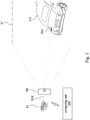
- Fig. 1 is a schematic diagram of a system for providing a simulated environment according to some embodiments of present disclosure.
- the simulated environment is an environment built with virtual objects illustrated by computing units, for example, may be a virtual reality environment, an augmented reality environment or a mixed reality environment.
- a first wearable device 100 is in communication with a computing unit 200.
- the first wearable device 100 is carried by a first user (now shown).
- the first wearable device 100 is configured to output a first scenario S1 of a virtual reality environment to the first user, wherein the first scenario may be updated according to the viewing that changed in response to the movement of the first user.
- the first wearable device 100 may receive signals from the computing unit 200 for displaying and updating the first scenario S1.
- the first scenario S1 is being displayed on the display (now shown) of the first wearable device 100 instead of being projected to the real world.
- the first scenario S1 being displayed shows a partial view of the virtual reality environment from a viewpoint of the first user.
- a virtual roadster VT is presented in the virtual environment.
- the first user may see the tail of the virtual roadster VT with eyeball E1.
- the first wearable device 100 may track a first direction EO1 of the eyeball E1 with an optical sensor (not shown) configured on the first wearable device 100.
- the first wearable device 100 may provide a first indicator IN1 in the first scenario S1 according to the first direction EO1.
- the first direction EO1 is the direction extended from the pupil of the eyeball E1, wherein the first direction EO1 is perpendicular to the surface of the pupil.
- the first indicator IN1 is provided for indicating where the first user is looking at in the first scenario S1.
- the first indicator IN1 is pointed on the left side of the tail of the virtual roadster VT, which indicates that the first wearable device 100 tracks the eyeball E1 is pointing to the point of the first indicator IN1.
- the computing unit 200 is configured to determine which portion of the virtual roadster VT is pointed by the first indicator IN1, and further to store first information corresponding to the portion being pointed. As shown in Fig. 1 , the computing unit 200 may determine the left side of the tail of the virtual roadster VT is pointed by the first indicator IN1, so the computing unit 200 may store first information corresponding to the left side of the tail of the virtual roadster VT. The first information may be a frequency count regarding to which portion of the virtual roadster VT is pointed by the first indicator IN1.
- the frequency count regarding to that first portion is being pointed may be stored.
- the frequency count regarding to that second portion is being pointed may be stored.
- the first information may also be an image or a video regarding to the portion being pointed by the first indicator IN1 in the first scenario S1.
- the computing unit 200 may trigger the first wearable device 100 to capture an instant image of the first scenario S1.
- the instant image being captured may indicate that the left side of the tail of the virtual roadster VT is being pointed by the first indicator IN1.
- the computing unit 200 may determine that the first user is looking at the specific portion of the virtual roadster VT from which viewpoint.
- the first indicator IN1 is merely an indication to the first wearable device 100 and the computing unit 200 so the first user may not observe the first indicator IN1 in the first scenario S1.
- the computing unit 200 when the computing unit 200 stores the first information corresponding to the portion being pointed, the computing unit 200 may perform an operation according to the first information. For example, the computing unit 200 may highlight the portion of the virtual roadster VT with specific marks or colors, and the first user may observe the portion being highlighted in the first scenario S1. In another example, the computing unit 200 may conceal the portion of the virtual roadster VT with virtual objects or colors, and the first user may not observe the portion being concealed in the first scenario S1. In some other examples, the computing unit 200 may reshape the portion of the virtual roadster VT in the first scenario S1, or the computing unit 200 may send a notification regarding the portion of the virtual object.
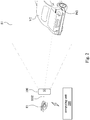
- Fig. 2 is a schematic diagram of a system for providing a simulated environment according to the embodiment shown in Fig. 1 .
- the same first scenario S1 is outputted by the first wearable device 100, and the tail of the virtual roadster VT is displayed in the first scenario S1 as well.
- the first wearable device 100 may track a second direction EO2 of the eyeball E1 and provide a second indicator IN2 in the first scenario S1 according to the second direction EO2.
- the second direction EO2 is the direction extended from center of the eyeball E1 to the pupil of the eyeball E1.
- the second indicator IN2 is provided for indicating where the first user (not shown) is looking at in the first scenario S1.
- the second indicator IN2 is pointed on the right side of the tail of the virtual roadster VT, which indicates that the first wearable device 100 tracks the eyeball E1 is pointing to the point of the second indicator IN2.
- the computing unit 200 is configured to determine which portion of the virtual roadster VT is pointed by the second indicator IN2, and further to store second information corresponding to the portion being pointed. As shown in Fig. 2 , the computing unit 200 may determine that the right side of the tail of the virtual roadster VT is pointed by the second indicator IN2, so the computing unit 200 may store second information corresponding to the right side of the tail of the virtual roadster VT. The second information may be a frequency count regarding to which portion of the virtual roadster VT is pointed by the second indicator IN2.
- the first information and the second information are both frequency counts regarding to which portion of the virtual roadster VT is being pointed by indicators, if the first indicator IN1 and the second indicator IN2 are being determined as pointing to the same portion of the virtual roadster VT, the first information and the second information may be accumulated. As such, through analyzing the first information and the second information, it can be known that the first user likes or dislikes some specific portions of the virtual roadster VT.
- the computing unit 200 when the computing unit 200 stores the first information and the second information, the computing unit 200 may perform an operation according to the first information and the second information. For example, the computing unit 200 may highlight or conceal the portion of the virtual roadster VT, and the first user may observe the portion being highlighted or hidden in the first scenario S1.
- Fig. 3 is a schematic diagram of a system for providing a simulated environment according to some embodiments of present disclosure.
- a third wearable device 300 and a fourth wearable device 400 is in communication with a computing unit 500.
- the third wearable device 300 is carried by a third user and the fourth wearable device 400 is carried by a fourth user.
- the third wearable device 300 is configured to output a third scenario of a virtual reality environment to the third user
- the fourth wearable device 400 is configured to output a fourth scenario of the virtual reality environment to a fourth user.
- a virtual roadster VT is displayed in both the third scenario and the fourth scenario.
- the scenario S5 being displayed shows a partial view of the virtual reality environment from the viewpoints of the third user and the fourth user.
- the tail of the virtual roadster VT is presented in both the third scenario and the fourth scenario, as shown in the scenario S5.
- the third user may see the tail of the virtual roadster VT with eyeball E3.
- the third wearable device 300 may track a third direction EO3 of the eyeball E3 and provide a third indicator IN3 in the third scenario according to the third direction EO3.
- the fourth user may see the tail of the virtual roadster VT with eyeball E4.
- the fourth wearable device 400 may track a fourth direction EO4 of the eyeball E4 and provide a fourth indicator IN4 in the fourth scenario according to the fourth direction EO4. It can be seen in scenario S5, the third indicator IN3 is pointing to the left side of the tail of the virtual roadster VT and the fourth indicator IN4 is pointing to the right side of the tail of the virtual roadster VT.
- the computing unit 500 is configured to determine which portion of the virtual roadster VT is pointed by the third indicator IN3 and the fourth indicator IN4.
- the computing unit 500 is further configured to store third information corresponding to the portion being pointed by the third indicator IN3 and to store fourth information corresponding to the portion being pointed by the fourth indicator IN4.
- the computing unit 500 may determine the left side of the tail of the virtual roadster VT is pointed by the third indicator IN3, so the computing unit 500 may store third information corresponding to the left side of the tail of the virtual roadster VT.
- the computing unit 500 may determine the right side of the tail of the virtual roadster VT is pointed by the fourth indicator IN4, so the computing unit 500 may store fourth information corresponding to the right side of the tail of the virtual roadster VT.
- the computing unit 500 when the computing unit 500 stores the third information and the fourth information, the computing unit 200 may perform an operation according to the third information and the fourth information. For example, the computing unit 500 may send a notification about the portion of the virtual roadster VT, and the third user and the fourth user may observe the notification in the scenario S5.
- the third information may be a frequency count regarding to which portion of the virtual roadster VT is pointed by the third indicator IN3
- the fourth information may be a frequency count regarding to which portion of the virtual roadster VT is pointed by the fourth indicator IN4. Since the third information and the fourth information are both frequency counts, so if it is the same portion of the virtual roadster VT being pointed by the third indicator IN3 and the fourth indicator IN4, the third information and the fourth information may be accumulated as fifth information. It is to say, when the computing unit 500 is in communication with several wearable devices, the computing unit 500 may collect the information regarding to which portion of the virtual roadster VT is focused by all the users. Through analyzing the fifth information, it can be known that the third user and the fourth user like or dislike some specific portions of the virtual roadster VT.
- the fifth information may also be an image or a video regarding to the portion being pointed by the third indicator IN3 and the fourth indicator IN4.
- a plurality of coordinates may be spread on a surface of the virtual roadster VT in the virtual environment.
- the computing unit 500 may determine which of the coordinates is pointed by third indicator IN3 and the fourth indicator IN4. As such, the computing unit 500 may determine which portion of the virtual roadster VT is being pointed by the third indicator IN3 and the fourth indicator IN4 in a higher accuracy.
- the third indicator IN3 and the fourth indicator IN4 are merely indications to the wearable devices 300, 400 and the computing unit 500. The third user may not observe the third indicator IN3 in the third scenario, and the fourth user may not observe the fourth indicator IN4 in the fourth scenario.
- Fig. 4 is a schematic diagram of a system for providing a simulated environment according to some embodiments of present disclosure.
- a sixth wearable device 600 is in communication with a computing unit 700.
- the sixth wearable device 600 is carried by a sixth user U6.
- the sixth wearable device 600 is configured to output a sixth scenario S6 of a virtual reality environment to the sixth user U6.
- a virtual roadster VT is displayed in the sixth scenario S6.
- the tail of the virtual roadster VT is presented in the sixth scenario S6.
- the sixth user U6 may see the tail of the virtual roadster VT.
- the sixth user U6 may point to a specific portion of the virtual roadster VT with his finger F1 when he wants to discuss the portion of the virtual roadster VT.
- the sixth wearable device 600 may track a sixth direction FO6 of the finger F1 with a camera (not shown) configured on the sixth wearable device 600.
- the sixth wearable device 600 may provide a sixth indicator IN6 in the sixth scenario S6 according to the sixth direction FO6. It can be seen in sixth direction FO6, the sixth indicator IN6 is pointing to the middle of the tail of the virtual roadster VT.
- the computing unit 700 may determine that the middle of the tail of the virtual roadster VT is pointed by the sixth indicator IN6 and store sixth information accordingly.
- the computing unit 700 when the computing unit 700 stores the sixth information, the computing unit 700 may perform an operation according to the sixth information. For example, the computing unit 500 may reshape the portion in the middle of the tail of the virtual roadster VT, and the sixth user U6 may see the reshaped portion in the sixth scenario S6.
- the computing unit of present disclosure provides an approach to collect information about which portion of a virtual object is frequently observed by users or the opposite, the collected information may be used for analysis. Through the analysis, decent or flawed portions of the virtual object may be discovered.
- the computing unit 300 illustrated in abovementioned figures is only an example.
- the computing unit 200, the computing unit 500 and the computing unit 700 may be a CPU, GPU, or some control unit configured in the wearable devices.
- the computing unit may determine which portion of the virtual roadster VT is pointed by the indicators and store information accordingly.
- Fig. 5 is a flow chart of a method for providing a simulated environment according to some embodiments of present disclosure. The steps of the method will be listed and explained in detail in following segments.
- Step S501 outputting, by a first wearable device, a first scenario of the simulated environment, wherein a virtual object is displayed in the first scenario.
- the first wearable device 100 may output the first scenario S1 of the virtual reality environment to the first user.
- the first scenario S1 the virtual roadster VT may be presented to the first user, and the first user may see the tail of the virtual roadster VT with his eyeball E1.
- Step S502 tracking, by the first wearable device, a first direction of a first object.
- the first wearable device 100 may track a first direction EO1 of the eyeball E1.
- the first direction EO1 is the direction extended from center of the eyeball E1 to the pupil of the eyeball E1.
- Step S503 providing, by the first wearable device, a first indicator in the first scenario according to the first direction.
- a first indicator IN1 is provided in the first scenario S1.
- the first indicator IN1 is provided for indicating where the first user is looking at in the first scenario S1.
- the first indicator IN1 is pointed on the left side of the tail of the virtual roadster VT, which indicates that the first wearable device 100 tracks the eyeball E1 is pointing to the point of the first indicator IN1.
- Step S504 determining, by a computing unit, which portion of the virtual object is pointed by the first indicator.
- the computing unit 200 is configured to determine which portion of the virtual roadster VT is pointed by the first indicator IN1, and further to store first information corresponding to the portion being pointed.
- the computing unit 200 may determine the left side of the tail of the virtual roadster VT is pointed by the first indicator IN1.
- the computing unit 200 may determine the right side of the tail of the virtual roadster VT is pointed by the first indicator IN1.
- Step S505 storing, by the computing unit, first information corresponding to the portion being pointed.
- the computing unit 200 is configured to store information corresponding to the portion of the virtual roadster VT being pointed.
- the computing unit 200 may store first information corresponding to the left side of the tail of the virtual roadster VT.
- the computing unit 200 may store second information corresponding to the right side of the tail of the virtual roadster VT.
- the first information and the second information may be frequency counts regarding to which portion of the virtual roadster VT is pointed by the first indicator IN1. When the first indicator IN1 is being determined as pointing to the same portion of the virtual roadster VT again, the frequency counts add up.
- Step S506 performing, by the computing unit, an operation according to the first information.
- the computing unit 200 when the computing unit 200 stores the first information and the second information corresponding to the portion of the virtual roadster VT being pointed, the computing unit 200 may perform an operation to the portion of the virtual roadster VT according to the first information and the second information.
- the operation can be highlighting the portion of the virtual roadster VT, concealing the portion of the virtual roadster VT, reshaping the portion of the virtual roadster VT, or sending a notification regarding the portion of the virtual roadster VT.
Landscapes
- Engineering & Computer Science (AREA)
- General Engineering & Computer Science (AREA)
- Theoretical Computer Science (AREA)
- Physics & Mathematics (AREA)
- General Physics & Mathematics (AREA)
- Human Computer Interaction (AREA)
- Multimedia (AREA)
- Signal Processing (AREA)
- Optics & Photonics (AREA)
- Architecture (AREA)
- Computer Graphics (AREA)
- Computer Hardware Design (AREA)
- Software Systems (AREA)
- User Interface Of Digital Computer (AREA)
- Processing Or Creating Images (AREA)
Abstract
Description
- This application claims priority to
U.S. Provisional Application Serial Number 62/482,207, filed on April 06, 2017 - Present disclosure relates to a system and a method for providing a simulated environment.
- Virtual reality technology is very powerful when being applied to a group of people, especially when being applied for holding a conference or a workshop. It is much intuitive for having a prototype or a blueprint being presented in a visible three dimensional space rather than only on a two dimensional picture. However, there are still some unsolved problems for providing a virtual reality environment to multiple users located in different places.
- The disclosure relates to a system for providing a simulated environment. The system comprises a first wearable device and a computing unit. The first wearable device is configured to output a first scenario of the simulated environment, wherein a virtual object is being displayed in the first scenario. The first wearable device is further configured to track a first direction of a first object and provide a first indicator in the first scenario according to the first direction. The computing unit is configured to determine which portion of the virtual object is pointed by the first indicator, to store first information corresponding to the portion of the virtual object being pointed, and to perform an operation according to the first information.
- Another aspect of present disclosure is to provide a method for providing a simulated environment. The method comprises following steps: outputting, by a first wearable device, a first scenario of the simulated environment, wherein a virtual object is displayed in the first scenario; tracking, by the first wearable device, a first direction of a first object; providing, by the first wearable device, a first indicator in the first scenario according to the first direction; determining, by a computing unit, which portion of the virtual object is pointed by the first indicator; determining, by the computing unit, first information corresponding to the portion of the virtual object being pointed; and performing, by the computing unit, an operation according to the first information.
- It is to be understood that both the foregoing general description and the following detailed description are by examples, and are intended to provide further explanation of the disclosure as claimed.
- Present disclosure can be more fully understood by reading the following detailed description of the embodiment, with reference made to the accompanying drawings as follows:
-
Fig. 1 is a schematic diagram of a system for providing a simulated environment according to some embodiments of present disclosure; -
Fig. 2 is a schematic diagram of a system for providing a simulated environment according to the embodiment shown inFig. 1 ; -
Fig. 3 is a schematic diagram of a system for providing a simulated environment according to some embodiments of present disclosure; -
Fig. 4 is a schematic diagram of a system for providing a simulated environment according to some embodiments of present disclosure; and -
Fig. 5 is a chart of a method for providing a simulated environment according to some embodiments of present disclosure. - Reference will now be made in detail to the present embodiments of the disclosure, examples of which are illustrated in the accompanying drawings. Wherever possible, the same reference numbers are used in the drawings and the description to refer to the same or like parts.
- The terms used in this specification generally have their ordinary meanings in the art and in the specific context where each term is used. The use of examples in this specification, including examples of any terms discussed herein, is illustrative only, and in no way limits the scope and meaning of the disclosure or of any exemplified term. Likewise, the present disclosure is not limited to various embodiments given in this specification.
- As used herein, the terms "comprising," "including," "having," and the like are to be understood to be open-ended, i.e., to mean including but not limited to.
- Reference throughout the specification to "one embodiment" or "an embodiment" means that a particular feature, structure, implementation, or characteristic described in connection with the embodiment is included in at least one embodiment of the present disclosure. Thus, uses of the phrases "in one embodiment" or "in an embodiment" in various places throughout the specification are not necessarily all referring to the same embodiment. Furthermore, the particular features, structures, implementation, or characteristics may be combined in any suitable manner in one or more embodiments.
- In the following description and claims, the terms "coupled" and "connected", along with their derivatives, may be used. In particular embodiments, "connected" and "coupled" may be used to indicate that two or more elements are in direct physical or electrical contact with each other, or may also mean that two or more elements may be in indirect contact with each other. "Coupled" and "connected" may still be used to indicate that two or more elements cooperate or interact with each other.
-
Fig. 1 is a schematic diagram of a system for providing a simulated environment according to some embodiments of present disclosure. The simulated environment is an environment built with virtual objects illustrated by computing units, for example, may be a virtual reality environment, an augmented reality environment or a mixed reality environment. As shown inFig. 1 , a firstwearable device 100 is in communication with acomputing unit 200. In an embodiment, the firstwearable device 100 is carried by a first user (now shown). The firstwearable device 100 is configured to output a first scenario S1 of a virtual reality environment to the first user, wherein the first scenario may be updated according to the viewing that changed in response to the movement of the first user. The firstwearable device 100 may receive signals from thecomputing unit 200 for displaying and updating the first scenario S1. The first scenario S1 is being displayed on the display (now shown) of the firstwearable device 100 instead of being projected to the real world. The first scenario S1 being displayed shows a partial view of the virtual reality environment from a viewpoint of the first user. - As illustrated in
Fig. 1 , a virtual roadster VT is presented in the virtual environment. Through the first scenario S1, the first user may see the tail of the virtual roadster VT with eyeball E1. In the embodiment, the firstwearable device 100 may track a first direction EO1 of the eyeball E1 with an optical sensor (not shown) configured on the firstwearable device 100. The firstwearable device 100 may provide a first indicator IN1 in the first scenario S1 according to the first direction EO1. The first direction EO1 is the direction extended from the pupil of the eyeball E1, wherein the first direction EO1 is perpendicular to the surface of the pupil. The first indicator IN1 is provided for indicating where the first user is looking at in the first scenario S1. As can be seen in the figure, the first indicator IN1 is pointed on the left side of the tail of the virtual roadster VT, which indicates that the firstwearable device 100 tracks the eyeball E1 is pointing to the point of the first indicator IN1. - In the embodiment, the
computing unit 200 is configured to determine which portion of the virtual roadster VT is pointed by the first indicator IN1, and further to store first information corresponding to the portion being pointed. As shown inFig. 1 , thecomputing unit 200 may determine the left side of the tail of the virtual roadster VT is pointed by the first indicator IN1, so thecomputing unit 200 may store first information corresponding to the left side of the tail of the virtual roadster VT. The first information may be a frequency count regarding to which portion of the virtual roadster VT is pointed by the first indicator IN1. - For example, when the first indicator IN1 is being determined as pointing to a first portion of the virtual roadster VT, the frequency count regarding to that first portion is being pointed may be stored. And when the first indicator IN1 is being determined as pointing to a second portion of the virtual roadster VT, the frequency count regarding to that second portion is being pointed may be stored. As such, through the first information, it can be known that how many times the first user is looking at a specific portion of the virtual roadster VT.
- In the embodiment, the first information may also be an image or a video regarding to the portion being pointed by the first indicator IN1 in the first scenario S1. For example, when the first indicator IN1 is being determined as pointing to a first portion of the virtual roadster VT, the
computing unit 200 may trigger the firstwearable device 100 to capture an instant image of the first scenario S1. The instant image being captured may indicate that the left side of the tail of the virtual roadster VT is being pointed by the first indicator IN1. - In the embodiment, when the first information is stored by the
computing unit 200, the current position of the firstwearable device 100 with respect to the space it is located in may be recorded as well. Through this approach, thecomputing unit 200 may determine that the first user is looking at the specific portion of the virtual roadster VT from which viewpoint. In some embodiment, the first indicator IN1 is merely an indication to the firstwearable device 100 and thecomputing unit 200 so the first user may not observe the first indicator IN1 in the first scenario S1. - In the embodiment, when the
computing unit 200 stores the first information corresponding to the portion being pointed, thecomputing unit 200 may perform an operation according to the first information. For example, thecomputing unit 200 may highlight the portion of the virtual roadster VT with specific marks or colors, and the first user may observe the portion being highlighted in the first scenario S1. In another example, thecomputing unit 200 may conceal the portion of the virtual roadster VT with virtual objects or colors, and the first user may not observe the portion being concealed in the first scenario S1. In some other examples, thecomputing unit 200 may reshape the portion of the virtual roadster VT in the first scenario S1, or thecomputing unit 200 may send a notification regarding the portion of the virtual object. -
Fig. 2 is a schematic diagram of a system for providing a simulated environment according to the embodiment shown inFig. 1 . As shown inFig. 2 , in the embodiment, the same first scenario S1 is outputted by the firstwearable device 100, and the tail of the virtual roadster VT is displayed in the first scenario S1 as well. In the embodiment, the firstwearable device 100 may track a second direction EO2 of the eyeball E1 and provide a second indicator IN2 in the first scenario S1 according to the second direction EO2. The second direction EO2 is the direction extended from center of the eyeball E1 to the pupil of the eyeball E1. The second indicator IN2 is provided for indicating where the first user (not shown) is looking at in the first scenario S1. As can be seen in the figure, the second indicator IN2 is pointed on the right side of the tail of the virtual roadster VT, which indicates that the firstwearable device 100 tracks the eyeball E1 is pointing to the point of the second indicator IN2. - In the same manner, in the embodiment, the
computing unit 200 is configured to determine which portion of the virtual roadster VT is pointed by the second indicator IN2, and further to store second information corresponding to the portion being pointed. As shown inFig. 2 , thecomputing unit 200 may determine that the right side of the tail of the virtual roadster VT is pointed by the second indicator IN2, so thecomputing unit 200 may store second information corresponding to the right side of the tail of the virtual roadster VT. The second information may be a frequency count regarding to which portion of the virtual roadster VT is pointed by the second indicator IN2. However, according to the embodiment ofFig. 1 , since the first information and the second information are both frequency counts regarding to which portion of the virtual roadster VT is being pointed by indicators, if the first indicator IN1 and the second indicator IN2 are being determined as pointing to the same portion of the virtual roadster VT, the first information and the second information may be accumulated. As such, through analyzing the first information and the second information, it can be known that the first user likes or dislikes some specific portions of the virtual roadster VT. - In the embodiment, when the
computing unit 200 stores the first information and the second information, thecomputing unit 200 may perform an operation according to the first information and the second information. For example, thecomputing unit 200 may highlight or conceal the portion of the virtual roadster VT, and the first user may observe the portion being highlighted or hidden in the first scenario S1. -
Fig. 3 is a schematic diagram of a system for providing a simulated environment according to some embodiments of present disclosure. As shown inFig. 3 , a thirdwearable device 300 and a fourthwearable device 400 is in communication with acomputing unit 500. In an embodiment, the thirdwearable device 300 is carried by a third user and the fourthwearable device 400 is carried by a fourth user. The thirdwearable device 300 is configured to output a third scenario of a virtual reality environment to the third user, and the fourthwearable device 400 is configured to output a fourth scenario of the virtual reality environment to a fourth user. A virtual roadster VT is displayed in both the third scenario and the fourth scenario. However, since the third user and the fourth user are viewing the virtual roadster VT from similar viewpoints in the virtual reality environment, so what can be observed in the third scenario and the fourth scenario are basically the same, as shown as a scenario S5 inFig. 3 . The scenario S5 being displayed shows a partial view of the virtual reality environment from the viewpoints of the third user and the fourth user. - As illustrated in
Fig. 3 , the tail of the virtual roadster VT is presented in both the third scenario and the fourth scenario, as shown in the scenario S5. In the embodiment, through the third scenario, the third user may see the tail of the virtual roadster VT with eyeball E3. The thirdwearable device 300 may track a third direction EO3 of the eyeball E3 and provide a third indicator IN3 in the third scenario according to the third direction EO3. Through the fourth scenario, the fourth user may see the tail of the virtual roadster VT with eyeball E4. The fourthwearable device 400 may track a fourth direction EO4 of the eyeball E4 and provide a fourth indicator IN4 in the fourth scenario according to the fourth direction EO4. It can be seen in scenario S5, the third indicator IN3 is pointing to the left side of the tail of the virtual roadster VT and the fourth indicator IN4 is pointing to the right side of the tail of the virtual roadster VT. - In the embodiment, the
computing unit 500 is configured to determine which portion of the virtual roadster VT is pointed by the third indicator IN3 and the fourth indicator IN4. Thecomputing unit 500 is further configured to store third information corresponding to the portion being pointed by the third indicator IN3 and to store fourth information corresponding to the portion being pointed by the fourth indicator IN4. As shown inFig. 3 , thecomputing unit 500 may determine the left side of the tail of the virtual roadster VT is pointed by the third indicator IN3, so thecomputing unit 500 may store third information corresponding to the left side of the tail of the virtual roadster VT. Thecomputing unit 500 may determine the right side of the tail of the virtual roadster VT is pointed by the fourth indicator IN4, so thecomputing unit 500 may store fourth information corresponding to the right side of the tail of the virtual roadster VT. - In the embodiment, when the
computing unit 500 stores the third information and the fourth information, thecomputing unit 200 may perform an operation according to the third information and the fourth information. For example, thecomputing unit 500 may send a notification about the portion of the virtual roadster VT, and the third user and the fourth user may observe the notification in the scenario S5. - In the embodiment, the third information may be a frequency count regarding to which portion of the virtual roadster VT is pointed by the third indicator IN3, and the fourth information may be a frequency count regarding to which portion of the virtual roadster VT is pointed by the fourth indicator IN4. Since the third information and the fourth information are both frequency counts, so if it is the same portion of the virtual roadster VT being pointed by the third indicator IN3 and the fourth indicator IN4, the third information and the fourth information may be accumulated as fifth information. It is to say, when the
computing unit 500 is in communication with several wearable devices, thecomputing unit 500 may collect the information regarding to which portion of the virtual roadster VT is focused by all the users. Through analyzing the fifth information, it can be known that the third user and the fourth user like or dislike some specific portions of the virtual roadster VT. - In the embodiment, the fifth information may also be an image or a video regarding to the portion being pointed by the third indicator IN3 and the fourth indicator IN4. Furthermore, in some embodiments, a plurality of coordinates may be spread on a surface of the virtual roadster VT in the virtual environment. The
computing unit 500 may determine which of the coordinates is pointed by third indicator IN3 and the fourth indicator IN4. As such, thecomputing unit 500 may determine which portion of the virtual roadster VT is being pointed by the third indicator IN3 and the fourth indicator IN4 in a higher accuracy. In some embodiment, the third indicator IN3 and the fourth indicator IN4 are merely indications to thewearable devices computing unit 500. The third user may not observe the third indicator IN3 in the third scenario, and the fourth user may not observe the fourth indicator IN4 in the fourth scenario. -
Fig. 4 is a schematic diagram of a system for providing a simulated environment according to some embodiments of present disclosure. As shown inFig. 4 , a sixthwearable device 600 is in communication with acomputing unit 700. In an embodiment, the sixthwearable device 600 is carried by a sixth user U6. The sixthwearable device 600 is configured to output a sixth scenario S6 of a virtual reality environment to the sixth user U6. A virtual roadster VT is displayed in the sixth scenario S6. - As illustrated in
Fig. 4 , the tail of the virtual roadster VT is presented in the sixth scenario S6. In the embodiment, through the sixth scenario S6, the sixth user U6 may see the tail of the virtual roadster VT. The sixth user U6 may point to a specific portion of the virtual roadster VT with his finger F1 when he wants to discuss the portion of the virtual roadster VT. The sixthwearable device 600 may track a sixth direction FO6 of the finger F1 with a camera (not shown) configured on the sixthwearable device 600. The sixthwearable device 600 may provide a sixth indicator IN6 in the sixth scenario S6 according to the sixth direction FO6. It can be seen in sixth direction FO6, the sixth indicator IN6 is pointing to the middle of the tail of the virtual roadster VT. Thecomputing unit 700 may determine that the middle of the tail of the virtual roadster VT is pointed by the sixth indicator IN6 and store sixth information accordingly. - In the embodiment, when the
computing unit 700 stores the sixth information, thecomputing unit 700 may perform an operation according to the sixth information. For example, thecomputing unit 500 may reshape the portion in the middle of the tail of the virtual roadster VT, and the sixth user U6 may see the reshaped portion in the sixth scenario S6. - As described, not only the direction of user's eyeballs may be collected by the computing unit of present disclosure, so does the direction of user's limbs. Present disclosure provides an approach to collect information about which portion of a virtual object is frequently observed by users or the opposite, the collected information may be used for analysis. Through the analysis, decent or flawed portions of the virtual object may be discovered.
- However, it should be understood that the
computing unit 300 illustrated in abovementioned figures is only an example. In some embodiments, thecomputing unit 200, thecomputing unit 500 and thecomputing unit 700 may be a CPU, GPU, or some control unit configured in the wearable devices. Depends on which wearable device is configured with the computing unit, the computing unit may determine which portion of the virtual roadster VT is pointed by the indicators and store information accordingly. -
Fig. 5 is a flow chart of a method for providing a simulated environment according to some embodiments of present disclosure. The steps of the method will be listed and explained in detail in following segments. - Step S501: outputting, by a first wearable device, a first scenario of the simulated environment, wherein a virtual object is displayed in the first scenario. As shown in the embodiment of
Fig. 1 andFig. 2 , the firstwearable device 100 may output the first scenario S1 of the virtual reality environment to the first user. In the first scenario S1, the the virtual roadster VT may be presented to the first user, and the first user may see the tail of the virtual roadster VT with his eyeball E1. - Step S502: tracking, by the first wearable device, a first direction of a first object. As shown in the embodiment of
Fig. 1 andFig. 2 , the firstwearable device 100 may track a first direction EO1 of the eyeball E1. The first direction EO1 is the direction extended from center of the eyeball E1 to the pupil of the eyeball E1. - Step S503: providing, by the first wearable device, a first indicator in the first scenario according to the first direction. As shown in the embodiment of
Fig. 1 andFig. 2 , according to the first direction EO1, a first indicator IN1 is provided in the first scenario S1. The first indicator IN1 is provided for indicating where the first user is looking at in the first scenario S1. As can be seen in the figure, the first indicator IN1 is pointed on the left side of the tail of the virtual roadster VT, which indicates that the firstwearable device 100 tracks the eyeball E1 is pointing to the point of the first indicator IN1. - Step S504: determining, by a computing unit, which portion of the virtual object is pointed by the first indicator. As shown in the embodiment of
Fig. 1 andFig. 2 , thecomputing unit 200 is configured to determine which portion of the virtual roadster VT is pointed by the first indicator IN1, and further to store first information corresponding to the portion being pointed. As shown inFig. 1 , thecomputing unit 200 may determine the left side of the tail of the virtual roadster VT is pointed by the first indicator IN1. As shown inFig. 2 , thecomputing unit 200 may determine the right side of the tail of the virtual roadster VT is pointed by the first indicator IN1. - Step S505: storing, by the computing unit, first information corresponding to the portion being pointed. As shown in the embodiment of
Fig. 1 andFig. 2 , thecomputing unit 200 is configured to store information corresponding to the portion of the virtual roadster VT being pointed. As shown inFig. 1 , thecomputing unit 200 may store first information corresponding to the left side of the tail of the virtual roadster VT. As shown inFig. 2 , thecomputing unit 200 may store second information corresponding to the right side of the tail of the virtual roadster VT. The first information and the second information may be frequency counts regarding to which portion of the virtual roadster VT is pointed by the first indicator IN1. When the first indicator IN1 is being determined as pointing to the same portion of the virtual roadster VT again, the frequency counts add up. - Step S506: performing, by the computing unit, an operation according to the first information. As shown in the embodiment of
Fig. 1 andFig. 2 , when thecomputing unit 200 stores the first information and the second information corresponding to the portion of the virtual roadster VT being pointed, thecomputing unit 200 may perform an operation to the portion of the virtual roadster VT according to the first information and the second information. In some embodiments, the operation can be highlighting the portion of the virtual roadster VT, concealing the portion of the virtual roadster VT, reshaping the portion of the virtual roadster VT, or sending a notification regarding the portion of the virtual roadster VT. - Although the present disclosure has been described in considerable detail with reference to certain embodiments thereof, other embodiments are possible. Therefore, the spirit and scope of the appended claims should not be limited to the description of the embodiments contained herein.
- It will be apparent to those skilled in the art that various modifications and variations can be made to the structure of the present disclosure without departing from the scope or spirit of the disclosure. In view of the foregoing, it is intended that the present disclosure cover modifications and variations of this disclosure provided they fall within the scope of the following claims.
Claims (15)
- A system for providing a simulated environment, comprising:a first wearable device (100), configured to output a first scenario of the simulated environment and a virtual object is displayed in the first scenario, wherein the first wearable device is further configured to track a first direction of a first object and provide a first indicator in the first scenario according to the first direction; anda computing unit (200), configured to determine which portion of the virtual object is pointed by the first indicator, to store first information corresponding to the portion of the virtual object being pointed, and to perform an operation according to the first information.
- The system of claim 1, wherein the first information is a frequency count regarding which portion of the first object is pointed by the first indicator.
- The system of claim 1 or 2, wherein a plurality of coordinates are spread on a surface of the virtual object in the virtual environment, wherein the computing unit (200) is configured to determine which of the coordinates is pointed by the first indicator in order to determine which portion of the virtual object is being pointed.
- The system of any one of the preceding claims, wherein the first information is an image regarding to the portion of the virtual object in the first scenario.
- The system of any one of the preceding claims, wherein the first object is a sphere, wherein the first direction is extended from and perpendicular to a point on the surface of the sphere.
- The system of any one of the preceding claims, wherein the operation comprises highlighting the portion of the virtual object, concealing the portion of the virtual object, reshaping the portion of the virtual object and sending a notification regarding the portion of the virtual object.
- A method for providing a simulated environment, comprising:outputting, by a first wearable device, a first scenario of the simulated environment, wherein a virtual object is displayed in the first scenario;tracking, by the first wearable device, a first direction of a first object;providing, by the first wearable device, a first indicator in the first scenario according to the first direction;determining, by a computing unit, which portion of the virtual object is pointed by the first indicator;storing, by the computing unit, first information corresponding to the portion of the virtual object being pointed; andperforming, by the computing unit, an operation according to the first information.
- The method of claim 7, wherein the first information is a frequency count regarding which portion of the first object is pointed by the first indicator.
- The method of any one of the preceding claims 7 to 8, further comprising:recording, by the computing unit, a position of the first wearable device when the first information is being stored by the computing unit.
- The method of any one of the preceding claims 7 to 9, further comprising:outputting, by a second wearable device, a second scenario of the simulated environment, wherein the virtual object is displayed in the second scenario;tracking, by the second wearable device, a second direction of a second object;providing, by the second wearable device, a second indicator in the second scenario according to the second direction;determining, by the computing unit, which portion of the virtual object is pointed by the second indicator;storing, by the computing unit, second information corresponding to the portion being pointed; andperforming, by the computing unit, an operation according to the second information.
- The method of claim 10, wherein the first information is a first frequency count regarding to which portion of the virtual object is pointed by the first indicator, and the second information is a second frequency count regarding to which portion of the virtual object is pointed by the second indicator, wherein the first frequency count and the second frequency count are accumulated as a third frequency count when the portion being pointed by the first indicator is the same as the portion being pointed by the second indicator.
- The method of any one of the preceding claims 7 to 11, wherein a plurality of coordinates are spread on a surface of the virtual object in the virtual environment, wherein the computing unit is configured to determine which of the coordinates is pointed by the first indicator in order to determine which portion of the virtual object is being pointed.
- The method of any one of the preceding claims 7 to 12, wherein the first information is an image regarding to the portion of the virtual object in the first scenario.
- The method of any one of the preceding claims 7 to 13, wherein the first object is a sphere, wherein the first direction is extended from and perpendicular to a point on the surface of the sphere.
- The method of any one of the preceding claims 7 to 14, wherein the operation comprises highlighting the portion of the virtual object, concealing the portion of the virtual object, reshaping the portion of the virtual object and sending a notification regarding the portion of the virtual object.
Applications Claiming Priority (2)
| Application Number | Priority Date | Filing Date | Title |
|---|---|---|---|
| US201762482207P | 2017-04-06 | 2017-04-06 | |
| US15/823,607 US10401957B2 (en) | 2017-04-06 | 2017-11-28 | System and method for providing simulated environment |
Publications (2)
| Publication Number | Publication Date |
|---|---|
| EP3385822A1 true EP3385822A1 (en) | 2018-10-10 |
| EP3385822B1 EP3385822B1 (en) | 2020-06-24 |
Family
ID=60953795
Family Applications (1)
| Application Number | Title | Priority Date | Filing Date |
|---|---|---|---|
| EP18151332.6A Active EP3385822B1 (en) | 2017-04-06 | 2018-01-12 | System and method for providing simulated environment |
Country Status (4)
| Country | Link |
|---|---|
| US (1) | US10401957B2 (en) |
| EP (1) | EP3385822B1 (en) |
| CN (1) | CN108693964B (en) |
| TW (1) | TWI669654B (en) |
Families Citing this family (3)
| Publication number | Priority date | Publication date | Assignee | Title |
|---|---|---|---|---|
| US11831665B2 (en) | 2021-01-04 | 2023-11-28 | Bank Of America Corporation | Device for monitoring a simulated environment |
| US11682136B2 (en) * | 2021-01-07 | 2023-06-20 | Htc Corporation | Display method, display system and non-transitory computer readable storage medium |
| US11693479B2 (en) * | 2021-09-28 | 2023-07-04 | Htc Corporation | Virtual image display device and object selection method for virtual image thereof |
Citations (4)
| Publication number | Priority date | Publication date | Assignee | Title |
|---|---|---|---|---|
| US20130050432A1 (en) * | 2011-08-30 | 2013-02-28 | Kathryn Stone Perez | Enhancing an object of interest in a see-through, mixed reality display device |
| WO2016014878A1 (en) * | 2014-07-25 | 2016-01-28 | Microsoft Technology Licensing, Llc | Gaze-based object placement within a virtual reality environment |
| US9363569B1 (en) * | 2014-07-28 | 2016-06-07 | Jaunt Inc. | Virtual reality system including social graph |
| US20160173865A1 (en) * | 2014-12-11 | 2016-06-16 | Hyundai Motor Company | Wearable glasses, control method thereof, and vehicle control system |
Family Cites Families (3)
| Publication number | Priority date | Publication date | Assignee | Title |
|---|---|---|---|---|
| CN104571776A (en) | 2013-10-22 | 2015-04-29 | 胜华科技股份有限公司 | Electronic device |
| CN105653012A (en) | 2014-08-26 | 2016-06-08 | 蔡大林 | Multi-user immersion type full interaction virtual reality project training system |
| KR20160147636A (en) | 2015-06-15 | 2016-12-23 | 삼성전자주식회사 | Head Mounted Display Apparatus |
-
2017
- 2017-11-28 US US15/823,607 patent/US10401957B2/en active Active
-
2018
- 2018-01-04 TW TW107100372A patent/TWI669654B/en active
- 2018-01-09 CN CN201810018087.3A patent/CN108693964B/en active Active
- 2018-01-12 EP EP18151332.6A patent/EP3385822B1/en active Active
Patent Citations (4)
| Publication number | Priority date | Publication date | Assignee | Title |
|---|---|---|---|---|
| US20130050432A1 (en) * | 2011-08-30 | 2013-02-28 | Kathryn Stone Perez | Enhancing an object of interest in a see-through, mixed reality display device |
| WO2016014878A1 (en) * | 2014-07-25 | 2016-01-28 | Microsoft Technology Licensing, Llc | Gaze-based object placement within a virtual reality environment |
| US9363569B1 (en) * | 2014-07-28 | 2016-06-07 | Jaunt Inc. | Virtual reality system including social graph |
| US20160173865A1 (en) * | 2014-12-11 | 2016-06-16 | Hyundai Motor Company | Wearable glasses, control method thereof, and vehicle control system |
Also Published As
| Publication number | Publication date |
|---|---|
| TWI669654B (en) | 2019-08-21 |
| TW201837696A (en) | 2018-10-16 |
| CN108693964A (en) | 2018-10-23 |
| CN108693964B (en) | 2020-07-03 |
| US10401957B2 (en) | 2019-09-03 |
| US20180292899A1 (en) | 2018-10-11 |
| EP3385822B1 (en) | 2020-06-24 |
Similar Documents
| Publication | Publication Date | Title |
|---|---|---|
| JP6028351B2 (en) | Control device, electronic device, control method, and program | |
| JP2022545851A (en) | VIRTUAL OBJECT CONTROL METHOD AND APPARATUS, DEVICE, COMPUTER-READABLE STORAGE MEDIUM | |
| US9214139B2 (en) | Image display apparatus and image display method | |
| US20110218953A1 (en) | Design of systems for improved human interaction | |
| CN111880720B (en) | Virtual display method, device, equipment and computer readable storage medium | |
| CA2669409A1 (en) | Method for scripting inter-scene transitions | |
| US20230054973A1 (en) | Information processing apparatus, information processing method, and information processing program | |
| EP3385822B1 (en) | System and method for providing simulated environment | |
| US10074216B2 (en) | Information processing to display information based on position of the real object in the image | |
| TW201830205A (en) | Display device and method for controlling same | |
| US20200074655A1 (en) | Image acquisition device and method of operating image acquisition device | |
| KR20150085610A (en) | Portable and method for controlling the same | |
| EP3528024B1 (en) | Information processing device, information processing method, and program | |
| CN109640070A (en) | A kind of stereo display method, device, equipment and storage medium | |
| JP2013050882A (en) | Information processing program, information processing system, information processor, and information processing method | |
| KR20180120456A (en) | Apparatus for providing virtual reality contents based on panoramic image and method for the same | |
| JP6713591B1 (en) | Display control device, display control method, program, and non-transitory computer-readable information recording medium | |
| Brandão et al. | Using augmented reality to improve dismounted operators' situation awareness | |
| US20170092141A1 (en) | Providing live feedback using a wearable computing device | |
| JP2005157134A (en) | Information output method and apparatus, program, and computer-readable storage medium storing information output program | |
| US20230075650A1 (en) | Representation of Media Data | |
| JPWO2020031493A1 (en) | Terminal device and control method of terminal device | |
| Chung et al. | Panocue: An efficient visual cue with a omnidirectional panoramic view for finding a target in 3d space | |
| Mountain et al. | Mixed reality (MR) interfaces for mobile information systems | |
| JP2016186727A (en) | Video display device, video display method, and program |
Legal Events
| Date | Code | Title | Description |
|---|---|---|---|
| PUAI | Public reference made under article 153(3) epc to a published international application that has entered the european phase |
Free format text: ORIGINAL CODE: 0009012 |
|
| STAA | Information on the status of an ep patent application or granted ep patent |
Free format text: STATUS: REQUEST FOR EXAMINATION WAS MADE |
|
| 17P | Request for examination filed |
Effective date: 20180112 |
|
| AK | Designated contracting states |
Kind code of ref document: A1 Designated state(s): AL AT BE BG CH CY CZ DE DK EE ES FI FR GB GR HR HU IE IS IT LI LT LU LV MC MK MT NL NO PL PT RO RS SE SI SK SM TR |
|
| AX | Request for extension of the european patent |
Extension state: BA ME |
|
| RBV | Designated contracting states (corrected) |
Designated state(s): AL AT BE BG CH CY CZ DE DK EE ES FI FR GB GR HR HU IE IS IT LI LT LU LV MC MK MT NL NO PL PT RO RS SE SI SK SM TR |
|
| STAA | Information on the status of an ep patent application or granted ep patent |
Free format text: STATUS: EXAMINATION IS IN PROGRESS |
|
| 17Q | First examination report despatched |
Effective date: 20190628 |
|
| GRAP | Despatch of communication of intention to grant a patent |
Free format text: ORIGINAL CODE: EPIDOSNIGR1 |
|
| STAA | Information on the status of an ep patent application or granted ep patent |
Free format text: STATUS: GRANT OF PATENT IS INTENDED |
|
| INTG | Intention to grant announced |
Effective date: 20200123 |
|
| GRAS | Grant fee paid |
Free format text: ORIGINAL CODE: EPIDOSNIGR3 |
|
| GRAA | (expected) grant |
Free format text: ORIGINAL CODE: 0009210 |
|
| STAA | Information on the status of an ep patent application or granted ep patent |
Free format text: STATUS: THE PATENT HAS BEEN GRANTED |
|
| AK | Designated contracting states |
Kind code of ref document: B1 Designated state(s): AL AT BE BG CH CY CZ DE DK EE ES FI FR GB GR HR HU IE IS IT LI LT LU LV MC MK MT NL NO PL PT RO RS SE SI SK SM TR |
|
| REG | Reference to a national code |
Ref country code: GB Ref legal event code: FG4D |
|
| REG | Reference to a national code |
Ref country code: CH Ref legal event code: EP |
|
| REG | Reference to a national code |
Ref country code: DE Ref legal event code: R096 Ref document number: 602018005438 Country of ref document: DE |
|
| REG | Reference to a national code |
Ref country code: AT Ref legal event code: REF Ref document number: 1284553 Country of ref document: AT Kind code of ref document: T Effective date: 20200715 |
|
| REG | Reference to a national code |
Ref country code: IE Ref legal event code: FG4D |
|
| REG | Reference to a national code |
Ref country code: NL Ref legal event code: FP |
|
| PG25 | Lapsed in a contracting state [announced via postgrant information from national office to epo] |
Ref country code: LT Free format text: LAPSE BECAUSE OF FAILURE TO SUBMIT A TRANSLATION OF THE DESCRIPTION OR TO PAY THE FEE WITHIN THE PRESCRIBED TIME-LIMIT Effective date: 20200624 Ref country code: SE Free format text: LAPSE BECAUSE OF FAILURE TO SUBMIT A TRANSLATION OF THE DESCRIPTION OR TO PAY THE FEE WITHIN THE PRESCRIBED TIME-LIMIT Effective date: 20200624 Ref country code: GR Free format text: LAPSE BECAUSE OF FAILURE TO SUBMIT A TRANSLATION OF THE DESCRIPTION OR TO PAY THE FEE WITHIN THE PRESCRIBED TIME-LIMIT Effective date: 20200925 Ref country code: NO Free format text: LAPSE BECAUSE OF FAILURE TO SUBMIT A TRANSLATION OF THE DESCRIPTION OR TO PAY THE FEE WITHIN THE PRESCRIBED TIME-LIMIT Effective date: 20200924 Ref country code: FI Free format text: LAPSE BECAUSE OF FAILURE TO SUBMIT A TRANSLATION OF THE DESCRIPTION OR TO PAY THE FEE WITHIN THE PRESCRIBED TIME-LIMIT Effective date: 20200624 |
|
| REG | Reference to a national code |
Ref country code: LT Ref legal event code: MG4D |
|
| PG25 | Lapsed in a contracting state [announced via postgrant information from national office to epo] |
Ref country code: HR Free format text: LAPSE BECAUSE OF FAILURE TO SUBMIT A TRANSLATION OF THE DESCRIPTION OR TO PAY THE FEE WITHIN THE PRESCRIBED TIME-LIMIT Effective date: 20200624 Ref country code: LV Free format text: LAPSE BECAUSE OF FAILURE TO SUBMIT A TRANSLATION OF THE DESCRIPTION OR TO PAY THE FEE WITHIN THE PRESCRIBED TIME-LIMIT Effective date: 20200624 Ref country code: BG Free format text: LAPSE BECAUSE OF FAILURE TO SUBMIT A TRANSLATION OF THE DESCRIPTION OR TO PAY THE FEE WITHIN THE PRESCRIBED TIME-LIMIT Effective date: 20200924 Ref country code: RS Free format text: LAPSE BECAUSE OF FAILURE TO SUBMIT A TRANSLATION OF THE DESCRIPTION OR TO PAY THE FEE WITHIN THE PRESCRIBED TIME-LIMIT Effective date: 20200624 |
|
| REG | Reference to a national code |
Ref country code: AT Ref legal event code: MK05 Ref document number: 1284553 Country of ref document: AT Kind code of ref document: T Effective date: 20200624 |
|
| PG25 | Lapsed in a contracting state [announced via postgrant information from national office to epo] |
Ref country code: AL Free format text: LAPSE BECAUSE OF FAILURE TO SUBMIT A TRANSLATION OF THE DESCRIPTION OR TO PAY THE FEE WITHIN THE PRESCRIBED TIME-LIMIT Effective date: 20200624 |
|
| PG25 | Lapsed in a contracting state [announced via postgrant information from national office to epo] |
Ref country code: IT Free format text: LAPSE BECAUSE OF FAILURE TO SUBMIT A TRANSLATION OF THE DESCRIPTION OR TO PAY THE FEE WITHIN THE PRESCRIBED TIME-LIMIT Effective date: 20200624 Ref country code: SM Free format text: LAPSE BECAUSE OF FAILURE TO SUBMIT A TRANSLATION OF THE DESCRIPTION OR TO PAY THE FEE WITHIN THE PRESCRIBED TIME-LIMIT Effective date: 20200624 Ref country code: ES Free format text: LAPSE BECAUSE OF FAILURE TO SUBMIT A TRANSLATION OF THE DESCRIPTION OR TO PAY THE FEE WITHIN THE PRESCRIBED TIME-LIMIT Effective date: 20200624 Ref country code: PT Free format text: LAPSE BECAUSE OF FAILURE TO SUBMIT A TRANSLATION OF THE DESCRIPTION OR TO PAY THE FEE WITHIN THE PRESCRIBED TIME-LIMIT Effective date: 20201026 Ref country code: CZ Free format text: LAPSE BECAUSE OF FAILURE TO SUBMIT A TRANSLATION OF THE DESCRIPTION OR TO PAY THE FEE WITHIN THE PRESCRIBED TIME-LIMIT Effective date: 20200624 Ref country code: RO Free format text: LAPSE BECAUSE OF FAILURE TO SUBMIT A TRANSLATION OF THE DESCRIPTION OR TO PAY THE FEE WITHIN THE PRESCRIBED TIME-LIMIT Effective date: 20200624 Ref country code: EE Free format text: LAPSE BECAUSE OF FAILURE TO SUBMIT A TRANSLATION OF THE DESCRIPTION OR TO PAY THE FEE WITHIN THE PRESCRIBED TIME-LIMIT Effective date: 20200624 Ref country code: AT Free format text: LAPSE BECAUSE OF FAILURE TO SUBMIT A TRANSLATION OF THE DESCRIPTION OR TO PAY THE FEE WITHIN THE PRESCRIBED TIME-LIMIT Effective date: 20200624 |
|
| PG25 | Lapsed in a contracting state [announced via postgrant information from national office to epo] |
Ref country code: IS Free format text: LAPSE BECAUSE OF FAILURE TO SUBMIT A TRANSLATION OF THE DESCRIPTION OR TO PAY THE FEE WITHIN THE PRESCRIBED TIME-LIMIT Effective date: 20201024 Ref country code: PL Free format text: LAPSE BECAUSE OF FAILURE TO SUBMIT A TRANSLATION OF THE DESCRIPTION OR TO PAY THE FEE WITHIN THE PRESCRIBED TIME-LIMIT Effective date: 20200624 Ref country code: SK Free format text: LAPSE BECAUSE OF FAILURE TO SUBMIT A TRANSLATION OF THE DESCRIPTION OR TO PAY THE FEE WITHIN THE PRESCRIBED TIME-LIMIT Effective date: 20200624 |
|
| REG | Reference to a national code |
Ref country code: DE Ref legal event code: R097 Ref document number: 602018005438 Country of ref document: DE |
|
| PG25 | Lapsed in a contracting state [announced via postgrant information from national office to epo] |
Ref country code: DK Free format text: LAPSE BECAUSE OF FAILURE TO SUBMIT A TRANSLATION OF THE DESCRIPTION OR TO PAY THE FEE WITHIN THE PRESCRIBED TIME-LIMIT Effective date: 20200624 |
|
| PLBE | No opposition filed within time limit |
Free format text: ORIGINAL CODE: 0009261 |
|
| STAA | Information on the status of an ep patent application or granted ep patent |
Free format text: STATUS: NO OPPOSITION FILED WITHIN TIME LIMIT |
|
| 26N | No opposition filed |
Effective date: 20210325 |
|
| PG25 | Lapsed in a contracting state [announced via postgrant information from national office to epo] |
Ref country code: MC Free format text: LAPSE BECAUSE OF FAILURE TO SUBMIT A TRANSLATION OF THE DESCRIPTION OR TO PAY THE FEE WITHIN THE PRESCRIBED TIME-LIMIT Effective date: 20200624 Ref country code: SI Free format text: LAPSE BECAUSE OF FAILURE TO SUBMIT A TRANSLATION OF THE DESCRIPTION OR TO PAY THE FEE WITHIN THE PRESCRIBED TIME-LIMIT Effective date: 20200624 |
|
| REG | Reference to a national code |
Ref country code: CH Ref legal event code: PL |
|
| PG25 | Lapsed in a contracting state [announced via postgrant information from national office to epo] |
Ref country code: LU Free format text: LAPSE BECAUSE OF NON-PAYMENT OF DUE FEES Effective date: 20210112 |
|
| REG | Reference to a national code |
Ref country code: BE Ref legal event code: MM Effective date: 20210131 |
|
| PG25 | Lapsed in a contracting state [announced via postgrant information from national office to epo] |
Ref country code: CH Free format text: LAPSE BECAUSE OF NON-PAYMENT OF DUE FEES Effective date: 20210131 Ref country code: LI Free format text: LAPSE BECAUSE OF NON-PAYMENT OF DUE FEES Effective date: 20210131 |
|
| PG25 | Lapsed in a contracting state [announced via postgrant information from national office to epo] |
Ref country code: IE Free format text: LAPSE BECAUSE OF NON-PAYMENT OF DUE FEES Effective date: 20210112 |
|
| PG25 | Lapsed in a contracting state [announced via postgrant information from national office to epo] |
Ref country code: BE Free format text: LAPSE BECAUSE OF NON-PAYMENT OF DUE FEES Effective date: 20210131 |
|
| REG | Reference to a national code |
Ref country code: DE Ref legal event code: R082 Ref document number: 602018005438 Country of ref document: DE Representative=s name: WAGNER & GEYER PARTNERSCHAFT MBB PATENT- UND R, DE |
|
| PG25 | Lapsed in a contracting state [announced via postgrant information from national office to epo] |
Ref country code: CY Free format text: LAPSE BECAUSE OF FAILURE TO SUBMIT A TRANSLATION OF THE DESCRIPTION OR TO PAY THE FEE WITHIN THE PRESCRIBED TIME-LIMIT Effective date: 20200624 |
|
| P01 | Opt-out of the competence of the unified patent court (upc) registered |
Effective date: 20230602 |
|
| PG25 | Lapsed in a contracting state [announced via postgrant information from national office to epo] |
Ref country code: HU Free format text: LAPSE BECAUSE OF FAILURE TO SUBMIT A TRANSLATION OF THE DESCRIPTION OR TO PAY THE FEE WITHIN THE PRESCRIBED TIME-LIMIT; INVALID AB INITIO Effective date: 20180112 |
|
| PG25 | Lapsed in a contracting state [announced via postgrant information from national office to epo] |
Ref country code: MK Free format text: LAPSE BECAUSE OF FAILURE TO SUBMIT A TRANSLATION OF THE DESCRIPTION OR TO PAY THE FEE WITHIN THE PRESCRIBED TIME-LIMIT Effective date: 20200624 |
|
| PG25 | Lapsed in a contracting state [announced via postgrant information from national office to epo] |
Ref country code: MT Free format text: LAPSE BECAUSE OF FAILURE TO SUBMIT A TRANSLATION OF THE DESCRIPTION OR TO PAY THE FEE WITHIN THE PRESCRIBED TIME-LIMIT Effective date: 20200624 |
|
| PG25 | Lapsed in a contracting state [announced via postgrant information from national office to epo] |
Ref country code: TR Free format text: LAPSE BECAUSE OF FAILURE TO SUBMIT A TRANSLATION OF THE DESCRIPTION OR TO PAY THE FEE WITHIN THE PRESCRIBED TIME-LIMIT Effective date: 20200624 |
|
| PGFP | Annual fee paid to national office [announced via postgrant information from national office to epo] |
Ref country code: GB Payment date: 20251204 Year of fee payment: 9 |
|
| PGFP | Annual fee paid to national office [announced via postgrant information from national office to epo] |
Ref country code: NL Payment date: 20251215 Year of fee payment: 9 Ref country code: FR Payment date: 20251208 Year of fee payment: 9 |
|
| PGFP | Annual fee paid to national office [announced via postgrant information from national office to epo] |
Ref country code: DE Payment date: 20251203 Year of fee payment: 9 |