EP3385794A1 - Fixing device and image forming apparatus incorporating same - Google Patents
Fixing device and image forming apparatus incorporating same Download PDFInfo
- Publication number
- EP3385794A1 EP3385794A1 EP18163744.8A EP18163744A EP3385794A1 EP 3385794 A1 EP3385794 A1 EP 3385794A1 EP 18163744 A EP18163744 A EP 18163744A EP 3385794 A1 EP3385794 A1 EP 3385794A1
- Authority
- EP
- European Patent Office
- Prior art keywords
- nip
- fixing sleeve
- formation pad
- nip formation
- fixing device
- Prior art date
- Legal status (The legal status is an assumption and is not a legal conclusion. Google has not performed a legal analysis and makes no representation as to the accuracy of the status listed.)
- Withdrawn
Links
- 238000003825 pressing Methods 0.000 claims abstract description 85
- 230000015572 biosynthetic process Effects 0.000 claims abstract description 71
- 230000007246 mechanism Effects 0.000 claims abstract description 29
- 238000012546 transfer Methods 0.000 description 78
- 238000007639 printing Methods 0.000 description 18
- 239000010410 layer Substances 0.000 description 16
- 229910052736 halogen Inorganic materials 0.000 description 15
- 150000002367 halogens Chemical class 0.000 description 15
- 229920001971 elastomer Polymers 0.000 description 10
- 230000007423 decrease Effects 0.000 description 8
- 238000004140 cleaning Methods 0.000 description 7
- 238000010586 diagram Methods 0.000 description 6
- 239000002699 waste material Substances 0.000 description 6
- 239000000463 material Substances 0.000 description 5
- 238000000034 method Methods 0.000 description 5
- 230000005684 electric field Effects 0.000 description 4
- 229920001343 polytetrafluoroethylene Polymers 0.000 description 4
- 239000004810 polytetrafluoroethylene Substances 0.000 description 4
- 239000007787 solid Substances 0.000 description 4
- PXHVJJICTQNCMI-UHFFFAOYSA-N Nickel Chemical compound [Ni] PXHVJJICTQNCMI-UHFFFAOYSA-N 0.000 description 3
- 230000008859 change Effects 0.000 description 3
- 238000012545 processing Methods 0.000 description 3
- 229920005989 resin Polymers 0.000 description 3
- 239000011347 resin Substances 0.000 description 3
- 238000000926 separation method Methods 0.000 description 3
- 229920000106 Liquid crystal polymer Polymers 0.000 description 2
- 239000004977 Liquid-crystal polymers (LCPs) Substances 0.000 description 2
- 239000004743 Polypropylene Substances 0.000 description 2
- 238000005452 bending Methods 0.000 description 2
- 239000011248 coating agent Substances 0.000 description 2
- 238000000576 coating method Methods 0.000 description 2
- 238000012937 correction Methods 0.000 description 2
- 230000000694 effects Effects 0.000 description 2
- 238000002474 experimental method Methods 0.000 description 2
- 238000010438 heat treatment Methods 0.000 description 2
- 239000002184 metal Substances 0.000 description 2
- 229910052751 metal Inorganic materials 0.000 description 2
- 229920001155 polypropylene Polymers 0.000 description 2
- -1 polytetrafluoroethylene Polymers 0.000 description 2
- 229920002379 silicone rubber Polymers 0.000 description 2
- 239000004945 silicone rubber Substances 0.000 description 2
- 239000004642 Polyimide Substances 0.000 description 1
- 230000002159 abnormal effect Effects 0.000 description 1
- 239000003086 colorant Substances 0.000 description 1
- 230000000052 comparative effect Effects 0.000 description 1
- 238000010276 construction Methods 0.000 description 1
- 229920001577 copolymer Polymers 0.000 description 1
- 230000003247 decreasing effect Effects 0.000 description 1
- 230000001419 dependent effect Effects 0.000 description 1
- 239000003814 drug Substances 0.000 description 1
- 238000005516 engineering process Methods 0.000 description 1
- 229920006015 heat resistant resin Polymers 0.000 description 1
- 238000009413 insulation Methods 0.000 description 1
- 238000012986 modification Methods 0.000 description 1
- 230000004048 modification Effects 0.000 description 1
- 229910052759 nickel Inorganic materials 0.000 description 1
- 229920001721 polyimide Polymers 0.000 description 1
- 229920006395 saturated elastomer Polymers 0.000 description 1
- 229910001220 stainless steel Inorganic materials 0.000 description 1
- 239000010935 stainless steel Substances 0.000 description 1
- 239000002344 surface layer Substances 0.000 description 1
- 238000011144 upstream manufacturing Methods 0.000 description 1
Images




Classifications
-
- G—PHYSICS
- G03—PHOTOGRAPHY; CINEMATOGRAPHY; ANALOGOUS TECHNIQUES USING WAVES OTHER THAN OPTICAL WAVES; ELECTROGRAPHY; HOLOGRAPHY
- G03G—ELECTROGRAPHY; ELECTROPHOTOGRAPHY; MAGNETOGRAPHY
- G03G15/00—Apparatus for electrographic processes using a charge pattern
- G03G15/20—Apparatus for electrographic processes using a charge pattern for fixing, e.g. by using heat
- G03G15/2003—Apparatus for electrographic processes using a charge pattern for fixing, e.g. by using heat using heat
- G03G15/2014—Apparatus for electrographic processes using a charge pattern for fixing, e.g. by using heat using heat using contact heat
- G03G15/2053—Structural details of heat elements, e.g. structure of roller or belt, eddy current, induction heating
-
- G—PHYSICS
- G03—PHOTOGRAPHY; CINEMATOGRAPHY; ANALOGOUS TECHNIQUES USING WAVES OTHER THAN OPTICAL WAVES; ELECTROGRAPHY; HOLOGRAPHY
- G03G—ELECTROGRAPHY; ELECTROPHOTOGRAPHY; MAGNETOGRAPHY
- G03G15/00—Apparatus for electrographic processes using a charge pattern
- G03G15/20—Apparatus for electrographic processes using a charge pattern for fixing, e.g. by using heat
- G03G15/2003—Apparatus for electrographic processes using a charge pattern for fixing, e.g. by using heat using heat
- G03G15/2007—Apparatus for electrographic processes using a charge pattern for fixing, e.g. by using heat using heat using radiant heat, e.g. infrared lamps, microwave heaters
-
- G—PHYSICS
- G03—PHOTOGRAPHY; CINEMATOGRAPHY; ANALOGOUS TECHNIQUES USING WAVES OTHER THAN OPTICAL WAVES; ELECTROGRAPHY; HOLOGRAPHY
- G03G—ELECTROGRAPHY; ELECTROPHOTOGRAPHY; MAGNETOGRAPHY
- G03G15/00—Apparatus for electrographic processes using a charge pattern
- G03G15/20—Apparatus for electrographic processes using a charge pattern for fixing, e.g. by using heat
- G03G15/2003—Apparatus for electrographic processes using a charge pattern for fixing, e.g. by using heat using heat
- G03G15/2014—Apparatus for electrographic processes using a charge pattern for fixing, e.g. by using heat using heat using contact heat
- G03G15/2039—Apparatus for electrographic processes using a charge pattern for fixing, e.g. by using heat using heat using contact heat with means for controlling the fixing temperature
- G03G15/2042—Apparatus for electrographic processes using a charge pattern for fixing, e.g. by using heat using heat using contact heat with means for controlling the fixing temperature specially for the axial heat partition
-
- G—PHYSICS
- G03—PHOTOGRAPHY; CINEMATOGRAPHY; ANALOGOUS TECHNIQUES USING WAVES OTHER THAN OPTICAL WAVES; ELECTROGRAPHY; HOLOGRAPHY
- G03G—ELECTROGRAPHY; ELECTROPHOTOGRAPHY; MAGNETOGRAPHY
- G03G15/00—Apparatus for electrographic processes using a charge pattern
- G03G15/20—Apparatus for electrographic processes using a charge pattern for fixing, e.g. by using heat
- G03G15/2003—Apparatus for electrographic processes using a charge pattern for fixing, e.g. by using heat using heat
- G03G15/2014—Apparatus for electrographic processes using a charge pattern for fixing, e.g. by using heat using heat using contact heat
- G03G15/2064—Apparatus for electrographic processes using a charge pattern for fixing, e.g. by using heat using heat using contact heat combined with pressure
-
- G—PHYSICS
- G03—PHOTOGRAPHY; CINEMATOGRAPHY; ANALOGOUS TECHNIQUES USING WAVES OTHER THAN OPTICAL WAVES; ELECTROGRAPHY; HOLOGRAPHY
- G03G—ELECTROGRAPHY; ELECTROPHOTOGRAPHY; MAGNETOGRAPHY
- G03G2215/00—Apparatus for electrophotographic processes
- G03G2215/00362—Apparatus for electrophotographic processes relating to the copy medium handling
- G03G2215/00535—Stable handling of copy medium
- G03G2215/00717—Detection of physical properties
- G03G2215/00734—Detection of physical properties of sheet size
-
- G—PHYSICS
- G03—PHOTOGRAPHY; CINEMATOGRAPHY; ANALOGOUS TECHNIQUES USING WAVES OTHER THAN OPTICAL WAVES; ELECTROGRAPHY; HOLOGRAPHY
- G03G—ELECTROGRAPHY; ELECTROPHOTOGRAPHY; MAGNETOGRAPHY
- G03G2215/00—Apparatus for electrophotographic processes
- G03G2215/20—Details of the fixing device or porcess
- G03G2215/2003—Structural features of the fixing device
- G03G2215/2016—Heating belt
- G03G2215/2035—Heating belt the fixing nip having a stationary belt support member opposing a pressure member
Definitions
- the present invention relates to a fixing device to fix an image on a recording medium and an image forming apparatus incorporating the fixing device.
- a fixing device for an image forming apparatus has a fixing member having a heat source and a pressure rotator pressed against the fixing member by a pressing mechanism.
- a recording sheet on which a toner image as a developer image is formed passes through a fixing nip where both the fixing member and the pressure rotator are pressed against each other, the toner image is thermally fixed on the recording sheet.
- Contemporary fixing devices use a fixing sleeve as a fixing member having a low heat capacity to save energy and shorten the time to first printing.
- JP-2007-334205-A and JP-2007-233011-A disclose such a fixing device that adopts quick start up method (hereinafter called as QSU method) that uses the fixing member having the low heat capacity.
- QSU method quick start up method
- a halogen heater or the like having a predetermined light emission length is used.
- Continuous printing of small-size sheets having a lateral width shorter than the light emission length causes continuous heating by the heat source to non-sheet-feed-sections of a fixing sleeve that are both outer sides of the small-size sheets because the small-size sheets do not absorb heat from the non-sheet-feed-sections.
- This continuous heating to the non-sheet-feed-sections causes temperature rise on the non-sheet-feed-sections of the fixing sleeve, which is called temperature rise at lateral ends.
- Printing a large-size sheet under the temperature rise at lateral ends causes abnormal fixing (that is called "hot offset") at an end portion of the large-size sheet corresponding to at least one of the non-sheet-feed-sections.
- JP 2007-193165-A discloses a method of setting the idle rotation time of the pressure rotator and the fixing sleeve, waiting until the temperature at the non-sheet-feed-sections goes down, and beginning print for the large-size sheet.
- JP 2015-102718-A discloses a fixing device having a heat transfer member that is attached to a nip-forming member to convey heat so that heat is evenly distributed in the pressure rotator to avoid the temperature rise at lateral ends.
- JP 2007-193165-A has a problem of decrease of productivity of the image forming apparatus
- JP 2015-102718-A has a problem that the heat transfer member does not have enough effect to suppress the temperature rise at lateral ends because the temperature of the heat transfer member is saturated when small-size sheets are printed for a long time.
- JP 2001-154525-A discloses technology that can set an optimum pressing force corresponding to a sheet type at the fixing nip, but has a problem that uniform increase or decrease of the nip width in the longitudinal direction makes it difficult to suppress the temperature rise at lateral ends.
- the present invention is made in view of the above problems, and an object of the present invention is suppressing the temperature rise at lateral ends after printing small-size sheets for a long time continuously without decrease of the productivity, and enabling printing the large-size sheet without a fixing failure.
- the fixing device includes a fixing sleeve, a pair of holders oppositely disposed in an axial direction of the fixing sleeve to rotatably support both ends of the fixing sleeve in the axial direction, a heater to heat the fixing sleeve, a nip formation pad, a pressing member, a pressing mechanism, and a controller.
- the nip formation pad is disposed between the pair of holders and has a regular crown-shaped surface abutted against an inner circumferential surface of the fixing sleeve.
- the pressing member is disposed opposite the fixing sleeve to form a nip with the nip formation pad in a state of abutting against the fixing sleeve, and rotates the fixing sleeve by rotation in the abutting state.
- the nip has a width in a direction perpendicular to the axial direction of the fixing sleeve.
- the pressing mechanism presses the pressing member toward the nip formation pad.
- the controller controls the pressing mechanism in two modes: a first mode, in which the pressing mechanism presses the pressing member toward the nip formation pad with a first pressing force to equalize the width of the nip in a longitudinal direction of the abutted surface, and a second mode, in which the pressing mechanism presses the pressing member toward the nip formation pad with a second pressing force greater than the first pressing force so that the width of the nip is smaller at both ends of the nip in the longitudinal direction than at a center of the nip in the longitudinal direction.
- the present invention can decrease heat transfer from both lateral end portions of the fixing sleeve to the recording medium in the second mode because the nip formation pad has a pressure surface with regular crown shape, and the controller of the pressing mechanism sets the nip width of the both lateral end portions in the longitudinal direction smaller than the nip width of the center portion in the longitudinal direction in the second mode. Therefore, the present invention can suppress the temperature rise at lateral ends without waiting time even after continuous printing of the small-size sheets for a long time and prevent the fixing failure at the lateral end portion of the large-size sheet occurring after the continuous printing of the small-size sheets.
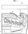
- the image forming apparatus 1000 is a color laser printer, and includes an image forming section A, a sheet feed section B, a fixing device 200, a curl correction device 300, a pair of sheet ejection rollers 13, and an output tray 14.
- the image forming section A includes four image forming units 4Y, 4M, 4C, and 4K, an exposure device 9, and a transfer device 3. Descriptions are given in further detail below.
- the image forming apparatus 1000 includes four image forming units 4Y, 4M, 4C, and 4K disposed in the center of the image forming apparatus 1000.
- the image forming units 4Y, 4M, 4C, and 4K contain developers (e.g., yellow, magenta, cyan, and black toners) in different colors, that is, yellow, magenta, cyan, and black corresponding to color separation components of a color image, respectively, the image forming units 4Y, 4M, 4C, and 4K have an identical structure.
- each of the image forming units 4Y, 4M, 4C, and 4K includes a drum-shaped photoconductor 5 as a latent image bearer; a charger 6 to charge a surface of the photoconductor 5; a developing device 7 to supply toner on the surface of the photoconductor 5; and a cleaning device 8 to clean the surface of the photoconductor 5.
- each of the photoconductor 5, the charger 6, the developing device 7, and the cleaning device 8 included in the black image forming unit 4K is supplied with a reference numeral and reference numerals for other image forming units 4Y, 4M, and 4C configured similarly to the image forming unit 4K are omitted.
- An exposure device 9 is disposed below the image forming units 4Y, 4M, 4C, and 4K and exposes the outer circumferential surfaces of the respective photoconductors 5 with laser beams.
- the exposure device 9 includes a laser light source, a polygon mirror, an f- ⁇ lens, and a plurality of reflection mirrors to irradiate the surface of each photoconductor 5 with a laser beam based on image data and form an electrostatic latent image on the surface of each photoconductor 5.
- a transfer device 3 is disposed above the image forming units 4Y, 4M, 4C, and 4K.
- the transfer device 3 includes an intermediate transfer belt 30 as an intermediate transfer member, four primary transfer rollers 31 as primary transfer members, a secondary transfer backup roller 32, a secondary transfer roller 36 as a secondary transfer member, a cleaning backup roller 33, a tension roller 34, and a belt cleaner 35.
- the intermediate transfer belt 30 is an endless belt stretched taut across the secondary transfer backup roller 32, the cleaning backup roller 33, and the tension roller 34. As a driver drives and rotates the secondary transfer backup roller 32 counterclockwise in FIG. 1 , the secondary transfer backup roller 32 rotates the intermediate transfer belt 30 counterclockwise in FIG. 1 , that is, in a rotation direction indicated by arrow E in FIG. 1 .
- the four primary transfer rollers 31 sandwich the intermediate transfer belt 30 together with the four photoconductors 5, forming four primary transfer nips between the intermediate transfer belt 30 and the photoconductors 5, respectively.
- each primary transfer roller 31 is connected to a power source and a predetermined direct current (DC) voltage or alternating current (AC) voltage is applied to each primary transfer roller 31.
- DC direct current
- AC alternating current
- the secondary transfer roller 36 sandwiches the intermediate transfer belt 30 together with the secondary transfer backup roller 32, forming a secondary transfer nip between the secondary transfer roller 36 and the intermediate transfer belt 30.
- the secondary transfer roller 36 is connected to a power source, and a predetermined direct current (DC) voltage or alternating current (AC) voltage is applied to the secondary transfer roller 36.
- the belt cleaner 35 includes a cleaning brush and a cleaning blade that contact an outer circumferential surface of the intermediate transfer belt 30.
- a waste toner drain tube extending from the belt cleaner 35 to an inlet of a waste toner container conveys waste toner collected from the intermediate transfer belt 30 by the belt cleaner 35 to the waste toner container.
- a bottle holder 2 disposed in an upper portion of the image forming apparatus 1000 accommodates four toner bottles 2Y, 2M, 2C, and 2K detachably attached to the bottle holder 2.
- the toner bottles 2Y, 2M, 2C, and 2K contain fresh yellow, magenta, cyan, and black toners to be supplied to the developing devices 7 of the image forming units 4Y, 4M, 4C, and 4K, respectively.
- the fresh yellow, magenta, cyan, and black toners are supplied from the toner bottles 2Y, 2M, 2C, and 2K to the developing devices 7 through toner supply tubes interposed between the toner bottles 2Y, 2M, 2C, and 2K and the developing devices 7, respectively.
- the sheet feed section B is disposed in the bottom of the image forming apparatus.
- the sheet feed section B includes a sheet tray 10 in which a recording medium P as a sheet material is contained, and a sheet feed roller 11 to feed the recording medium P from the sheet tray 10.
- the recording medium P may be thick paper, postcards, envelopes, plain paper, thin paper, coated paper, art paper, tracing paper, overhead projector (OHP) transparencies, and the like.
- the image forming apparatus 1000 may include a bypass feeder. According to the present embodiment, a sheet P having a basis weight of 160 grams/m 2 or more is defined as thick paper.
- a conveyance path R is disposed inside a body 100 of the image forming apparatus 1000.
- the recording medium P is conveyed from the sheet tray 10 to an outside of the body 100 via the secondary transfer nip.
- a registration roller pair 12 serving as a timing roller to convey the recording medium P to the secondary transfer nip at an appropriate timing for conveyance is disposed upstream from the secondary transfer roller 36 in the recording medium conveyance direction in the conveyance path R.
- the fixing device 200 presses and heats the recording medium P on which an unfixed image is borne and thereby fixes the toner image onto the recording medium P.
- the fixing device 200 is disposed downstream from the position of the secondary transfer roller 36 in the recording medium conveyance direction.
- a pair of sheet ejection rollers 13 to eject the recording medium P outside the body 100 of the image forming apparatus 1000 is disposed downstream from the fixing device 200 in the recording medium conveyance direction of the conveyance path R.
- the output tray 14 to stock the recording medium P ejected outside the image forming apparatus 1000 is disposed on an upper surface of the body 100 of the image forming apparatus 1000.
- a driver drives and rotates the photoconductors 5 of the image forming units 4Y, 4M, 4C, and 4K, respectively, clockwise in FIG. 1 .
- the chargers 6 uniformly charge the outer circumferential surface of the respective photoconductors 5 at a predetermined polarity.
- the exposure device 9 emits laser beams onto the charged outer circumferential surfaces of the respective photoconductors 5, respectively, thus forming electrostatic latent images on the photoconductors 5.
- the image data used to expose the respective photoconductors 5 is monochrome image data produced by decomposing a desired full color image into yellow, magenta, cyan, and black image data.
- the developing devices 7 supply yellow, magenta, cyan, and black toners to the electrostatic latent images formed on the photoconductors 5, visualizing the electrostatic latent images as yellow, magenta, cyan, and black toner visible images, respectively.
- the secondary transfer backup roller 32 is driven and rotated counterclockwise in FIG. 1 , and rotates the intermediate transfer belt 30 in the rotation direction illustrated by arrow E in FIG. 1 .
- the power supply applies a constant voltage or a constant current control voltage having a polarity opposite a polarity of the charged toner to the primary transfer rollers 31, creating transfer electric fields at the respective primary transfer nips formed between the photoconductors 5 and the primary transfer rollers 31.
- the transfer electrical fields generated in the primary transfer nips transfer and superimpose the toner images from the respective photoconductors 5 onto the intermediate transfer belt 30 to form a full color image on the outer circumferential surface of the intermediate transfer belt 30.
- the cleaning device 8 removes residual toner that has failed to be transferred onto the intermediate transfer belt 30 and has remained on the photoconductors 5. Thereafter, dischargers discharge the outer circumferential surfaces of the respective photoconductors 5, returning the outer circumferential surfaces of the respective photoconductors 5 to their initial surface potential.
- the sheet feed roller 11 disposed in the lower portion of the image forming apparatus 1000 is driven and rotated to feed the recording medium P from the sheet tray 10 toward the registration roller pair 12 through the conveyance path R.
- the registration roller pair 12 temporarily halts the recording medium P conveyed through the conveyance path R.
- the registration roller pair 12 resumes rotation at a predetermined time to convey the recording medium P to the secondary transfer nip at a time when the image formed on the intermediate transfer belt 30 reaches the secondary transfer nip.
- the secondary transfer roller 36 is supplied with a transfer voltage having a polarity opposite a polarity of the charged yellow, magenta, cyan, and black toners constructing the image formed on the intermediate transfer belt 30, thus creating a transfer electric field at the secondary transfer nip.
- the transfer electric field secondarily transfers the superimposed yellow, magenta, cyan, and black toner images constructing the image formed on the intermediate transfer belt 30 onto the recording medium P.
- the belt cleaner 35 removes residual toner that has failed to be transferred onto the recording medium P and has remained on the intermediate transfer belt 30.
- the removed toner is conveyed to and collected in the waste toner container.
- the recording medium P is conveyed to the fixing device 200, and the fixing device 200 fixes the toner image on the recording medium P.
- the recording medium P conveyed from the fixing device 200 is ejected to the output tray 14 outside the body 100 of the image forming apparatus 1000, after passing through the curl correction device 300.
- the image forming apparatus 1000 may form a monochrome toner image by using any one of the four image forming units 4Y, 4M, 4C, and 4K or may form a bicolor toner image or a tricolor toner image by using two or three of the image forming units 4Y, 4M, 4C, and 4K.
- the fixing device 200 includes a fixing sleeve 201 serving as a rotatable and endless fixing member and a pressure roller 203 serving as a pressing member that is rotatable, disposed opposite the fixing sleeve 201, and contacting an outer circumferential surface of the fixing sleeve 201.
- a first halogen heater 202A and a second halogen heater 202B serve as a fixing heat source.
- the halogen heaters 202 directly heat a region other than the nip portion of the fixing sleeve 201, that is, a region illustrated by an angular range ⁇ and an angular range ⁇ in FIG. 1 , with radiant heat from the inner circumferential side.
- a nip formation pad 206 is disposed closer to the pressure roller 203 than the halogen heater 202.
- a heat transfer member 216 is disposed as described later in FIG. 3 .
- a nip portion N is formed between the nip formation pad 206 and the pressure roller 203.
- the fixing sleeve 201 is an endless belt or film made of metal such as nickel and SUS stainless steel or resin such as polyimide.
- a pair of holders 208 oppositely disposed in the axial direction holds both ends of the fixing sleeve 201 rotatably.
- a surface layer of the fixing sleeve 201 has a release layer made of tetrafluoroethylene-perfluoroalkyl vinyl ether copolymer (PFA), polytetrafluoroethylene (PTFE), or the like to facilitate separation of toner and avoid toner adherence to the fixing sleeve201.
- PFA tetrafluoroethylene-perfluoroalkyl vinyl ether copolymer
- PTFE polytetrafluoroethylene
- An elastic layer made of silicone rubber or the like may be sandwiched between the base layer and the release layer such as a PFA layer or a PTFE layer. If the fixing sleeve 201 does not incorporate the elastic layer, the fixing sleeve 201 has a decreased thermal capacity that improves fixing property of being heated quickly to a desired fixing temperature at which the toner image is fixed on the recording medium. However, as the pressure roller 203 and the fixing sleeve 201 sandwich and press the unfixed toner image on the recording medium passing through the fixing nip N, slight surface asperities of the fixing sleeve 201 may be transferred onto the toner image on the recording medium, resulting in variation in gloss of the solid toner image that may appear as an orange peel image on the recording medium.
- the elastic layer made of silicone rubber has a thickness equal to or larger than about 100 micrometers. As the elastic layer deforms, the elastic layer absorbs slight surface asperities of the fixing sleeve 201, preventing formation of the faulty orange peel image.
- the pressure roller 203 is constructed of a core bar 205, an elastic rubber layer 204 coating the core bar 205, and a surface release layer coating the elastic rubber layer 204 and made of PFA or PTFE to facilitate separation of the recording medium from the pressure roller 203.
- a driving force generated by a driver e.g., a motor
- the pressure roller 203 rotates.
- the pressure roller 203 produces the fixing nip N having a predetermined length in the recording medium conveyance direction S.
- the pressure roller 203 may be a hollow roller or a solid roller. If the pressure roller 203 is a hollow roller, a heater such as a halogen heater may be disposed inside the hollow roller.
- the elastic rubber layer 204 may be made of solid rubber. Alternatively, if no heater is disposed inside the pressure roller 203, the elastic rubber layer 204 may be made of sponge rubber. The sponge rubber is preferable to the solid rubber because the sponge rubber has enhanced insulation that draws less heat from the fixing sleeve 201.
- a pressing mechanism 400 is configured to presses the pressure roller 203 against the nip formation pad 206 via the fixing sleeve 201.
- the pressing mechanism 400 includes a pressing arm 404 that presses a core bar 205 of the pressure roller 203 toward the nip formation pad 206 and a pressure spring 405 coupled to the pressing arm 404.
- One end of the pressing arm 404 on the left side in FIG. 2 is pivotally supported by a fixed support shaft, and the lower end of the pressure spring 405 is attached to the other end of the pressing arm 404 on the right side in FIG. 2 .
- the pressure roller 203 receives a strong urging force by the pressure spring 405 via the pressing arm 404 and presses against the fixing sleeve 201.
- the pressing mechanism 400 includes a stepping motor 416 and a movable bracket 417 that changes the urging force of the pressure spring 405.
- the upper end of the pressure spring 405 is coupled to the lower end of the movable bracket 417.
- a threaded rotary shaft 418 rotated by a stepping motor 416 is vertically threaded into the upper end portion of the movable bracket 417. Forward and reverse rotation, as an arrow Q in FIG. 2 , of the threaded rotary shaft 418 by the stepping motor 416 enables the movable bracket 417 to move vertically as arrow T in FIG. 2 .
- the controller 413 controls rotations of the stepping motor 416.
- a sheet information input mechanism 412 inputs sheet information (sheet size, a number of print, a print timing, and the like) of the recording medium P in the fixing device 200 to the controller 413.
- the pressing mechanism 400 described above is an example, and alternatively, any well-known technique such as changing the pushing amount of the cam can be used as appropriate.
- the nip formation pad 206 is a rectangular parallelepiped elongated in the axial direction and formed by a heat resistant resin or the like, and the heat transfer member 216 is disposed on the front side of the rectangular parallelepiped.
- a stay 207 having sufficient flexural rigidity to withstand the pressing force of the pressure roller 203 is disposed.
- These three members have lengths extending in the width direction or the axial direction (hereinafter referred to as "longitudinal direction") of the fixing sleeve 201. Both ends of the stay 207 are supported by a pair of holders 208 that hold both ends of the fixing sleeve 201 rotatable.
- Cut-out recesses 206a and 206b are formed at both end portions of the nip formation pad 206, and lateral end heaters 226a and 226b to compensate heat quantity of the halogen heaters 202 are disposed in the recesses 206a and 206b. Between the lateral end heaters 226a and 226b, a flat opposing reference surface 206c opposed to the pressure roller 203 is set, and the opposing reference surface 206c and the lateral end heaters 226a and 226b are covered with the heat transfer member 216.
- the heat transfer member 216 to equalize a temperature of the nip portion N in the axial direction equalizes a temperature of the fixing sleeve 201 in contact with the opposing reference surface 206c in the axial direction and prevents local temperature rise caused by the heat of the lateral end heaters 226a and 226b.
- An opposing face 216a of the front face of the heat transfer member 216 becomes a nip formation face that directly contacts the inner surface of the fixing sleeve 201, but, since the heat transfer member 216 is made of a thin sheet metal, from the aspect of mechanical strength, the opposing reference surface 206c of the nip formation pad 206 becomes the substantial nip formation face, and a pressing face that presses the inner circumferential surface of the fixing sleeve 201.
- the above described stay 207 serving as a support that supports the nip formation pad 206 to form the fixing nip N is disposed inside the loop formed by the fixing sleeve 201. As the nip formation pad 206 receives pressure from the pressure roller 203, the stay 207 supports the nip formation pad 206 to prevent bending of the nip formation pad 206 and produce an even nip width in an axial direction.
- the stay 207 has a shape having a projection projected from the opposite face to the fixing nip N side.
- the projection separates a first halogen heater 202A and a second halogen heater 202B as fixing heat sources from each other.
- These two halogen heaters 202 directly heat the inner surface of the fixing sleeve 201 with radiant heat. Disposing each of halogen heaters 202 inside the fixing sleeve 201 makes it easy to make the compact fixing device 200 including the rotatable endless fixing sleeve 201.
- the stay 207 is mounted on and held by flanges serving as a holder 208 at both lateral ends of the stay 207 in a longitudinal direction thereof parallel to the axial direction of the fixing sleeve 201, respectively, thus being positioned inside the fixing device 200.
- the reflector 209 interposed between the two halogen heaters 202 and the stay 207 prevents the stay 207 from being heated by each of the halogen heaters 202 with radiant heat and the like and thereby reducing waste of energy.
- the fixing sleeve 201 rotates in the rotation direction R2 in accordance with rotation of the pressure roller 203 by friction therebetween.
- the driver drives and rotates the pressure roller 203
- the driving force of the driver is transmitted from the pressure roller 203 to the fixing sleeve 201 at the fixing nip N, thus rotating the fixing sleeve 201 by friction between the pressure roller 203 and the fixing sleeve 201 in the present embodiment of FIG. 2 .
- the fixing sleeve 201 is sandwiched between the pressure roller 203 and the nip formation pad 206 and rotates; at a circumferential span of the fixing sleeve 201 other than the fixing nip N, the fixing sleeve 201 is guided by a flange of a pair of holders 208 disposed opposite to each other in the axial direction thereof and rotates.
- the fixing device 200 is a QSU type fixing device configured as described above, which shortens the warm-up time.
- the nip formation pad 206 is formed into a regular crown shape so that the thickness at the center in the longitudinal direction is maximized.
- the opposing reference surface 206c opposed to the pressure roller 203 is constituted as a flat surface in the longitudinal direction. Pressing force applied to the both ends of the pressure roller 203 from the pressing mechanism 400 deforms both end portions of the pressure roller 203 larger than a center portion of the pressure roller 203 on the opposing reference surface 206c. This pressing force also pushes the nip formation pad 206 and bends the center portion of the nip formation pad 206 in the longitudinal direction into a concave shape. Therefore, the increase in the pressing force of the pressure roller 203 increases the lateral end nip width, but always tends to leave the center nip width narrower as illustrated by the broken line in FIG. 5 .
- the opposing reference surface 206c of the nip formation pad 206 is formed into the regular crown shape as illustrated in FIG. 4 .
- the nip formation pad 206 has a shape that becomes thicker continuously symmetrically and smoothly from both ends to the center.
- the thickness of the nip formation pad 206 is greatest at the center portion in the longitudinal direction thereof.
- the pressing mechanism 400 described above is configured to press both ends of the pressure roller 203 toward the nip formation pad 206, as indicated by the arrows in FIG. 4 , and the controller 413 adjusts the magnitude of the pressing force.
- the controller 413 When an ordinary sheet is used, the controller 413 employs a first mode, that is, it applies small pressing force as a pressing force P1 to the pressure roller 203, and sets the nip width evenly in the longitudinal direction as illustrated in an one-dot chain line in FIG. 5 .
- the controller 413 employs a second mode, that is, the controller 413 changes the pressing force larger (P1 ⁇ P2) and applies a large pressing force as a second pressing force P2 to the pressure roller 203.
- the controller 413 sets the nip width at the center portion larger and the nip width at the end portions smaller than the nip width in the first mode as illustrated in a solid line in FIG. 5 .
- the second mode heat transfer from the nip portion N to the both end portions of the large-size sheet decreases, therefore, the fixing failure (hot offset) caused by the temperature rise at lateral ends is prevented.
- the small-size sheet means a recording medium having a lateral width D1 narrower than the longitudinal length of the halogen heater 202 as the heat source.
- the large-size sheet means a recording medium having a lateral width D2 larger than the lateral width D1 of the small-size sheet.
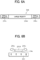
- FIGS. 6A and 6B illustrate a configuration in which the rigidity of the nip formation pad 206 is made different between the longitudinal center portion and both end portions.
- the pressing force of the pressure roller 203 may dent the center portion of the nip formation pad 206 having only the regular crown shape illustrated in FIG. 4 . Therefore, as illustrated in FIGS. 6A and 6B , the center portion 206d of the nip formation pad 206 is made of a material having large rigidity, and both end portions 206e of the nip formation pad 206 are made of a material having lower rigidity than the material of the center portion 206d. In this configuration, as illustrated in FIG.
- pressure from the pressure roller 203 to the nip formation pad 206 that presses the nip formation pad 206 in a direction of arrows in FIG.6B allows bending the end portions 206e but does not bend the center portion 206d as much, and as a result, decreases the lateral end nip width.
- the both end portions 206e may be made of polypropylene (PP) resin having low rigidity
- the center portion 206d may be made of liquid crystal polymer (LCP) resin having high rigidity
- a member of the center portion 206d and members of the both end portions 206e and 206f, each of which has different rigidity, may be arranged in the longitudinal direction of the nip formation pad 206, and be integrally assembled to the heat transfer member 216.
- Such a configuration as illustrated in FIGS. 7A and 7B can reduce the lateral end nip width and waiting time for large-size sheet printing after small-size continuous sheet printing.
- the nip formation pad 206 also includes both end portions 206g, and the stay 207 includes a connecting plate 207B.
- the stay 207 that supports the nip formation pad 206 has the regular crown shape in which the center portion in the longitudinal direction protrudes toward the pressure roller 203 similarly to the nip formation pad 206.
- This configuration enables the stay 207 to support the center portion of the nip formation pad 206, increase rigid strength of the center portion of the nip formation pad 206, and keep distribution of the nip width as illustrated by the solid line in FIG. 5 securely.
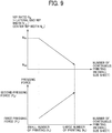
- FIG. 9 illustrates an example of pressing control in the second mode by the controller 413.
- the controller 413 continuously increases the magnitude of the pressing force in accordance with the number of continuous printing small-size sheets transmitted from the sheet information input mechanism 412. That is, as the number of continuous printing small-size sheets increases from the small number (Ni) to the large number (N 2 ) in FIG. 9 , the temperature at lateral ends rises. Therefore, in order to prevent the influence of the temperature rise at lateral ends, the controller 413 gradually increases the pressing force of the pressure roller 203, that is, increases a pressing force of the pressure roller 203 in proportion to an increase in the number of the small-size sheets, and makes the end nip width relatively smaller than the center portion nip width.
- a ratio N R of the lateral end nip width N L1 to the center nip width NL 2 decreases from the ratio N R1 at the small number of printing N 1 to the ratio N R2 at the large number of printing N 2 (N R1 > N R2 ).
- the controller 413 controls the ratio N R in the second mode smaller than the one in the first mode.
- This control effectively decreases the temperature rise at lateral ends and avoids increase of the waiting time and the fixing failure of the large-size sheet after small-size sheet printing.
- the increase of the center nip width leads to increase of heat given to a center portion of the large-size sheet, and this enables setting lower fixing temperature. Setting the lower fixing temperature saves energy. Although this effect is based on an inherent countermeasure, in the case of a medicine bag machine or the like, this second mode is important and useful.
- the controller 413 may control the magnitude of the pressing force based on a temperature detected by a temperature sensor disposed at the lateral end portion of the fixing sleeve 201 at which the temperature rise at the lateral ends occurs.
- a temperature sensor disposed at the lateral end portion of the fixing sleeve 201 at which the temperature rise at the lateral ends occurs.
- Processing circuitry includes a programmed processor, as a processor includes circuitry.
- a processing circuit also includes devices such as an application specific integrated circuit (ASIC), digital signal processor (DSP), field programmable gate array (FPGA), and conventional circuit components arranged to perform the recited functions.
- ASIC application specific integrated circuit
- DSP digital signal processor
- FPGA field programmable gate array
Landscapes
- Physics & Mathematics (AREA)
- General Physics & Mathematics (AREA)
- Fixing For Electrophotography (AREA)
Abstract
Description
- The present invention relates to a fixing device to fix an image on a recording medium and an image forming apparatus incorporating the fixing device.
- Generally, a fixing device for an image forming apparatus has a fixing member having a heat source and a pressure rotator pressed against the fixing member by a pressing mechanism. When a recording sheet on which a toner image as a developer image is formed passes through a fixing nip where both the fixing member and the pressure rotator are pressed against each other, the toner image is thermally fixed on the recording sheet.
- Contemporary fixing devices use a fixing sleeve as a fixing member having a low heat capacity to save energy and shorten the time to first printing.
- For example,
JP-2007-334205-A JP-2007-233011-A - As the heat source of the QSU system, a halogen heater or the like having a predetermined light emission length is used. Continuous printing of small-size sheets having a lateral width shorter than the light emission length causes continuous heating by the heat source to non-sheet-feed-sections of a fixing sleeve that are both outer sides of the small-size sheets because the small-size sheets do not absorb heat from the non-sheet-feed-sections. This continuous heating to the non-sheet-feed-sections causes temperature rise on the non-sheet-feed-sections of the fixing sleeve, which is called temperature rise at lateral ends. Printing a large-size sheet under the temperature rise at lateral ends causes abnormal fixing (that is called "hot offset") at an end portion of the large-size sheet corresponding to at least one of the non-sheet-feed-sections.
- As a countermeasure against this hot offset,
JP 2007-193165-A JP 2015-102718-A - However,
JP 2007-193165-A JP 2015-102718-A JP 2001-154525-A - The present invention is made in view of the above problems, and an object of the present invention is suppressing the temperature rise at lateral ends after printing small-size sheets for a long time continuously without decrease of the productivity, and enabling printing the large-size sheet without a fixing failure.
- It is a general object of the present invention to provide an improved and useful fixing device in which the above-mentioned problems are eliminated. In order to achieve the above-mentioned object, there is provided a fixing device according to claim 1. Advantageous embodiments are defined by the dependent claims. Advantageously, the fixing device includes a fixing sleeve, a pair of holders oppositely disposed in an axial direction of the fixing sleeve to rotatably support both ends of the fixing sleeve in the axial direction, a heater to heat the fixing sleeve, a nip formation pad, a pressing member, a pressing mechanism, and a controller. The nip formation pad is disposed between the pair of holders and has a regular crown-shaped surface abutted against an inner circumferential surface of the fixing sleeve. The pressing member is disposed opposite the fixing sleeve to form a nip with the nip formation pad in a state of abutting against the fixing sleeve, and rotates the fixing sleeve by rotation in the abutting state. The nip has a width in a direction perpendicular to the axial direction of the fixing sleeve. The pressing mechanism presses the pressing member toward the nip formation pad. The controller controls the pressing mechanism in two modes: a first mode, in which the pressing mechanism presses the pressing member toward the nip formation pad with a first pressing force to equalize the width of the nip in a longitudinal direction of the abutted surface, and a second mode, in which the pressing mechanism presses the pressing member toward the nip formation pad with a second pressing force greater than the first pressing force so that the width of the nip is smaller at both ends of the nip in the longitudinal direction than at a center of the nip in the longitudinal direction.
- The present invention can decrease heat transfer from both lateral end portions of the fixing sleeve to the recording medium in the second mode because the nip formation pad has a pressure surface with regular crown shape, and the controller of the pressing mechanism sets the nip width of the both lateral end portions in the longitudinal direction smaller than the nip width of the center portion in the longitudinal direction in the second mode. Therefore, the present invention can suppress the temperature rise at lateral ends without waiting time even after continuous printing of the small-size sheets for a long time and prevent the fixing failure at the lateral end portion of the large-size sheet occurring after the continuous printing of the small-size sheets.
- The aforementioned and other aspects, features, and advantages of the present invention would be better understood by reference to the following detailed description when considered in connection with the accompanying drawings, wherein:
-
FIG. 1 is a schematic view of an image forming apparatus according to an embodiment of the present invention; -
FIG. 2 is a schematic view of a fixing device according to the embodiment of the present invention; -
FIG. 3 is an exploded perspective view of a nip formation pad; -
FIG. 4 is a schematic layout view of the nip forming pad, a pressure roller, and a pressing mechanism; -
FIG. 5 is an explanatory diagram illustrating a change in a nip width in a longitudinal direction, which is caused by a change of a pressing force; -
FIG. 6A is an explanatory diagram illustrating a rigidity distribution in the nip formation pad; -
FIG. 6B is an explanatory diagram illustrating the nip formation pad deformed under pressure from a pressure roller; -
FIG. 7A is a schematic diagram illustrating the nip formation pad assembled in a heat transfer member; -
FIG. 7B is an exploded perspective view of the nip formation pad; -
FIG. 8 is an explanatory diagram illustrating a variation of the nip formation pad; and -
FIG. 9 is an explanatory diagram illustrating a method of increasing the pressing force when a large-size sheet is printed after continuously feeding small-size sheets. - The accompanying drawings are intended to depict embodiments of the present invention and should not be interpreted to limit the scope thereof. The accompanying drawings are not to be considered as drawn to scale unless explicitly noted.
- In describing embodiments illustrated in the drawings, specific terminology is employed for the sake of clarity. However, the invention of this specification is not intended to be limited to the specific terminology so selected and it is to be understood that each specific element includes all technical equivalents that have a similar function, operate in a similar manner, and achieve a similar result.
- Although the embodiments are described with technical limitations with reference to the attached drawings, such description is not intended to limit the scope of the invention and all of the components or elements described in the embodiments of this invention are not necessarily indispensable.
- Referring now to the drawings, embodiments of the present invention are described below. In the drawings illustrating the following embodiments, the same reference codes are allocated to elements (members or components) having the same function or shape and redundant descriptions thereof are omitted below.
- Below, a fixing device and an image forming apparatus according to an embodiment of the present disclosure is described below.
- A description is provided of the construction of an
image forming apparatus 1000 according to an embodiment of the present disclosure. - As illustrated in
FIG. 1 , in the present embodiment, theimage forming apparatus 1000 is a color laser printer, and includes an image forming section A, a sheet feed section B, afixing device 200, acurl correction device 300, a pair ofsheet ejection rollers 13, and anoutput tray 14. The image forming section A includes fourimage forming units exposure device 9, and atransfer device 3. Descriptions are given in further detail below. - The
image forming apparatus 1000 includes fourimage forming units image forming apparatus 1000. Although theimage forming units image forming units - Specifically, each of the
image forming units device 7 to supply toner on the surface of the photoconductor 5; and a cleaning device 8 to clean the surface of the photoconductor 5. - In
FIG. 1 , each of the photoconductor 5, the charger 6, the developingdevice 7, and the cleaning device 8 included in the blackimage forming unit 4K is supplied with a reference numeral and reference numerals for otherimage forming units image forming unit 4K are omitted. - An
exposure device 9 is disposed below theimage forming units exposure device 9 includes a laser light source, a polygon mirror, an f-θ lens, and a plurality of reflection mirrors to irradiate the surface of each photoconductor 5 with a laser beam based on image data and form an electrostatic latent image on the surface of each photoconductor 5. - A
transfer device 3 is disposed above theimage forming units transfer device 3 includes anintermediate transfer belt 30 as an intermediate transfer member, fourprimary transfer rollers 31 as primary transfer members, a secondarytransfer backup roller 32, asecondary transfer roller 36 as a secondary transfer member, a cleaningbackup roller 33, a tension roller 34, and abelt cleaner 35. - The
intermediate transfer belt 30 is an endless belt stretched taut across the secondarytransfer backup roller 32, the cleaningbackup roller 33, and the tension roller 34. As a driver drives and rotates the secondarytransfer backup roller 32 counterclockwise inFIG. 1 , the secondarytransfer backup roller 32 rotates theintermediate transfer belt 30 counterclockwise inFIG. 1 , that is, in a rotation direction indicated by arrow E inFIG. 1 . - The four
primary transfer rollers 31 sandwich theintermediate transfer belt 30 together with the four photoconductors 5, forming four primary transfer nips between theintermediate transfer belt 30 and the photoconductors 5, respectively. In addition, eachprimary transfer roller 31 is connected to a power source and a predetermined direct current (DC) voltage or alternating current (AC) voltage is applied to eachprimary transfer roller 31. - The
secondary transfer roller 36 sandwiches theintermediate transfer belt 30 together with the secondarytransfer backup roller 32, forming a secondary transfer nip between thesecondary transfer roller 36 and theintermediate transfer belt 30. In addition, similarly to theprimary transfer rollers 31, thesecondary transfer roller 36 is connected to a power source, and a predetermined direct current (DC) voltage or alternating current (AC) voltage is applied to thesecondary transfer roller 36. - The
belt cleaner 35 includes a cleaning brush and a cleaning blade that contact an outer circumferential surface of theintermediate transfer belt 30. A waste toner drain tube extending from thebelt cleaner 35 to an inlet of a waste toner container conveys waste toner collected from theintermediate transfer belt 30 by thebelt cleaner 35 to the waste toner container. - A
bottle holder 2 disposed in an upper portion of theimage forming apparatus 1000 accommodates fourtoner bottles bottle holder 2. Thetoner bottles devices 7 of theimage forming units toner bottles devices 7 through toner supply tubes interposed between thetoner bottles devices 7, respectively. - The sheet feed section B is disposed in the bottom of the image forming apparatus. The sheet feed section B includes a
sheet tray 10 in which a recording medium P as a sheet material is contained, and asheet feed roller 11 to feed the recording medium P from thesheet tray 10. - The recording medium P may be thick paper, postcards, envelopes, plain paper, thin paper, coated paper, art paper, tracing paper, overhead projector (OHP) transparencies, and the like. The
image forming apparatus 1000 may include a bypass feeder. According to the present embodiment, a sheet P having a basis weight of 160 grams/m2 or more is defined as thick paper. - Further, a conveyance path R is disposed inside a
body 100 of theimage forming apparatus 1000. Through the conveyance path R, the recording medium P is conveyed from thesheet tray 10 to an outside of thebody 100 via the secondary transfer nip. Aregistration roller pair 12 serving as a timing roller to convey the recording medium P to the secondary transfer nip at an appropriate timing for conveyance is disposed upstream from thesecondary transfer roller 36 in the recording medium conveyance direction in the conveyance path R. - The fixing
device 200 presses and heats the recording medium P on which an unfixed image is borne and thereby fixes the toner image onto the recording medium P. The fixingdevice 200 is disposed downstream from the position of thesecondary transfer roller 36 in the recording medium conveyance direction. Further, a pair ofsheet ejection rollers 13 to eject the recording medium P outside thebody 100 of theimage forming apparatus 1000 is disposed downstream from the fixingdevice 200 in the recording medium conveyance direction of the conveyance path R. In addition, theoutput tray 14 to stock the recording medium P ejected outside theimage forming apparatus 1000 is disposed on an upper surface of thebody 100 of theimage forming apparatus 1000. - Next, basic operation of the
image forming apparatus 1000 according to an embodiment of the present invention is described. - As a print job starts, a driver drives and rotates the photoconductors 5 of the
image forming units FIG. 1 . The chargers 6 uniformly charge the outer circumferential surface of the respective photoconductors 5 at a predetermined polarity. Theexposure device 9 emits laser beams onto the charged outer circumferential surfaces of the respective photoconductors 5, respectively, thus forming electrostatic latent images on the photoconductors 5. - The image data used to expose the respective photoconductors 5 is monochrome image data produced by decomposing a desired full color image into yellow, magenta, cyan, and black image data. The developing
devices 7 supply yellow, magenta, cyan, and black toners to the electrostatic latent images formed on the photoconductors 5, visualizing the electrostatic latent images as yellow, magenta, cyan, and black toner visible images, respectively. - Simultaneously, as the print job starts, the secondary
transfer backup roller 32 is driven and rotated counterclockwise inFIG. 1 , and rotates theintermediate transfer belt 30 in the rotation direction illustrated by arrow E inFIG. 1 . The power supply applies a constant voltage or a constant current control voltage having a polarity opposite a polarity of the charged toner to theprimary transfer rollers 31, creating transfer electric fields at the respective primary transfer nips formed between the photoconductors 5 and theprimary transfer rollers 31. - The transfer electrical fields generated in the primary transfer nips transfer and superimpose the toner images from the respective photoconductors 5 onto the
intermediate transfer belt 30 to form a full color image on the outer circumferential surface of theintermediate transfer belt 30. - After the primary transfer of the yellow, magenta, cyan, and black toner images from the photoconductors 5 onto the
intermediate transfer belt 30, the cleaning device 8 removes residual toner that has failed to be transferred onto theintermediate transfer belt 30 and has remained on the photoconductors 5. Thereafter, dischargers discharge the outer circumferential surfaces of the respective photoconductors 5, returning the outer circumferential surfaces of the respective photoconductors 5 to their initial surface potential. - In the meantime, the
sheet feed roller 11 disposed in the lower portion of theimage forming apparatus 1000 is driven and rotated to feed the recording medium P from thesheet tray 10 toward theregistration roller pair 12 through the conveyance path R. Theregistration roller pair 12 temporarily halts the recording medium P conveyed through the conveyance path R. - Thereafter, the
registration roller pair 12 resumes rotation at a predetermined time to convey the recording medium P to the secondary transfer nip at a time when the image formed on theintermediate transfer belt 30 reaches the secondary transfer nip. Thesecondary transfer roller 36 is supplied with a transfer voltage having a polarity opposite a polarity of the charged yellow, magenta, cyan, and black toners constructing the image formed on theintermediate transfer belt 30, thus creating a transfer electric field at the secondary transfer nip. - The transfer electric field secondarily transfers the superimposed yellow, magenta, cyan, and black toner images constructing the image formed on the
intermediate transfer belt 30 onto the recording medium P. After the secondary transfer of the full color toner image from theintermediate transfer belt 30 onto the recording medium P, thebelt cleaner 35 removes residual toner that has failed to be transferred onto the recording medium P and has remained on theintermediate transfer belt 30. The removed toner is conveyed to and collected in the waste toner container. - Thereafter, the recording medium P is conveyed to the
fixing device 200, and the fixingdevice 200 fixes the toner image on the recording medium P. The recording medium P conveyed from the fixingdevice 200 is ejected to theoutput tray 14 outside thebody 100 of theimage forming apparatus 1000, after passing through thecurl correction device 300. - The above describes the image forming operation of the
image forming apparatus 1000 to form the full color image on the recording medium P. Alternatively, theimage forming apparatus 1000 may form a monochrome toner image by using any one of the fourimage forming units image forming units - Next, a description is given of the fixing
device 200 according to the present embodiment of the present invention. - As illustrated in
FIG. 2 , the fixingdevice 200 includes a fixingsleeve 201 serving as a rotatable and endless fixing member and apressure roller 203 serving as a pressing member that is rotatable, disposed opposite the fixingsleeve 201, and contacting an outer circumferential surface of the fixingsleeve 201. - Inside the fixing
sleeve 201, afirst halogen heater 202A and asecond halogen heater 202B (collectively referred to as halogen heaters 202) serve as a fixing heat source. The halogen heaters 202 directly heat a region other than the nip portion of the fixingsleeve 201, that is, a region illustrated by an angular range α and an angular range β inFIG. 1 , with radiant heat from the inner circumferential side. - Inside the fixing
sleeve 201, anip formation pad 206 is disposed closer to thepressure roller 203 than the halogen heater 202. On the front side of thenip formation pad 206, aheat transfer member 216 is disposed as described later inFIG. 3 . A nip portion N is formed between thenip formation pad 206 and thepressure roller 203. - The fixing
sleeve 201 is an endless belt or film made of metal such as nickel and SUS stainless steel or resin such as polyimide. A pair ofholders 208 oppositely disposed in the axial direction holds both ends of the fixingsleeve 201 rotatably. A surface layer of the fixingsleeve 201 has a release layer made of tetrafluoroethylene-perfluoroalkyl vinyl ether copolymer (PFA), polytetrafluoroethylene (PTFE), or the like to facilitate separation of toner and avoid toner adherence to the fixing sleeve201. - An elastic layer made of silicone rubber or the like may be sandwiched between the base layer and the release layer such as a PFA layer or a PTFE layer. If the fixing
sleeve 201 does not incorporate the elastic layer, the fixingsleeve 201 has a decreased thermal capacity that improves fixing property of being heated quickly to a desired fixing temperature at which the toner image is fixed on the recording medium. However, as thepressure roller 203 and the fixingsleeve 201 sandwich and press the unfixed toner image on the recording medium passing through the fixing nip N, slight surface asperities of the fixingsleeve 201 may be transferred onto the toner image on the recording medium, resulting in variation in gloss of the solid toner image that may appear as an orange peel image on the recording medium. To address this circumstance, the elastic layer made of silicone rubber has a thickness equal to or larger than about 100 micrometers. As the elastic layer deforms, the elastic layer absorbs slight surface asperities of the fixingsleeve 201, preventing formation of the faulty orange peel image. - In the present embodiment, the
pressure roller 203 is constructed of acore bar 205, anelastic rubber layer 204 coating thecore bar 205, and a surface release layer coating theelastic rubber layer 204 and made of PFA or PTFE to facilitate separation of the recording medium from thepressure roller 203. As a driving force generated by a driver (e.g., a motor) disposed inside thebody 100 of theimage forming apparatus 1000 that is depicted as a printer inFIG. 1 is transmitted to thepressure roller 203 through a gear train, thepressure roller 203 rotates. - A
pressing mechanism 400 described later presses thepressure roller 203 against thenip formation pad 206 via the fixingsleeve 201, that is, thepressure roller 203 is in an abutting state with the fixingsleeve 201. As thepressing mechanism 400 presses and deforms theelastic rubber layer 204 of thepressure roller 203, thepressure roller 203 produces the fixing nip N having a predetermined length in the recording medium conveyance direction S. - The
pressure roller 203 may be a hollow roller or a solid roller. If thepressure roller 203 is a hollow roller, a heater such as a halogen heater may be disposed inside the hollow roller. Theelastic rubber layer 204 may be made of solid rubber. Alternatively, if no heater is disposed inside thepressure roller 203, theelastic rubber layer 204 may be made of sponge rubber. The sponge rubber is preferable to the solid rubber because the sponge rubber has enhanced insulation that draws less heat from the fixingsleeve 201. - A
pressing mechanism 400 is configured to presses thepressure roller 203 against thenip formation pad 206 via the fixingsleeve 201. Thepressing mechanism 400 includes apressing arm 404 that presses acore bar 205 of thepressure roller 203 toward thenip formation pad 206 and apressure spring 405 coupled to thepressing arm 404. - One end of the
pressing arm 404 on the left side inFIG. 2 is pivotally supported by a fixed support shaft, and the lower end of thepressure spring 405 is attached to the other end of thepressing arm 404 on the right side inFIG. 2 . Thepressure roller 203 receives a strong urging force by thepressure spring 405 via thepressing arm 404 and presses against the fixingsleeve 201. - The
pressing mechanism 400 according to the present embodiment includes a steppingmotor 416 and a movable bracket 417 that changes the urging force of thepressure spring 405. The upper end of thepressure spring 405 is coupled to the lower end of the movable bracket 417. - A threaded
rotary shaft 418 rotated by a steppingmotor 416 is vertically threaded into the upper end portion of the movable bracket 417. Forward and reverse rotation, as an arrow Q inFIG. 2 , of the threadedrotary shaft 418 by the steppingmotor 416 enables the movable bracket 417 to move vertically as arrow T inFIG. 2 . - The
controller 413 controls rotations of the steppingmotor 416. A sheetinformation input mechanism 412 inputs sheet information (sheet size, a number of print, a print timing, and the like) of the recording medium P in thefixing device 200 to thecontroller 413. Thepressing mechanism 400 described above is an example, and alternatively, any well-known technique such as changing the pushing amount of the cam can be used as appropriate. - As illustrated in
FIG. 3 , thenip formation pad 206 is a rectangular parallelepiped elongated in the axial direction and formed by a heat resistant resin or the like, and theheat transfer member 216 is disposed on the front side of the rectangular parallelepiped. On the back side of thenip formation pad 206, astay 207 having sufficient flexural rigidity to withstand the pressing force of thepressure roller 203 is disposed. - These three members have lengths extending in the width direction or the axial direction (hereinafter referred to as "longitudinal direction") of the fixing
sleeve 201. Both ends of thestay 207 are supported by a pair ofholders 208 that hold both ends of the fixingsleeve 201 rotatable. - Cut-out
recesses nip formation pad 206, andlateral end heaters recesses lateral end heaters reference surface 206c opposed to thepressure roller 203 is set, and the opposingreference surface 206c and thelateral end heaters heat transfer member 216. - The
heat transfer member 216 to equalize a temperature of the nip portion N in the axial direction equalizes a temperature of the fixingsleeve 201 in contact with the opposingreference surface 206c in the axial direction and prevents local temperature rise caused by the heat of thelateral end heaters face 216a of the front face of theheat transfer member 216 becomes a nip formation face that directly contacts the inner surface of the fixingsleeve 201, but, since theheat transfer member 216 is made of a thin sheet metal, from the aspect of mechanical strength, the opposingreference surface 206c of thenip formation pad 206 becomes the substantial nip formation face, and a pressing face that presses the inner circumferential surface of the fixingsleeve 201. - The above described
stay 207 serving as a support that supports thenip formation pad 206 to form the fixing nip N is disposed inside the loop formed by the fixingsleeve 201. As thenip formation pad 206 receives pressure from thepressure roller 203, thestay 207 supports thenip formation pad 206 to prevent bending of thenip formation pad 206 and produce an even nip width in an axial direction. - The
stay 207 has a shape having a projection projected from the opposite face to the fixing nip N side. The projection separates afirst halogen heater 202A and asecond halogen heater 202B as fixing heat sources from each other. These two halogen heaters 202 directly heat the inner surface of the fixingsleeve 201 with radiant heat. Disposing each of halogen heaters 202 inside the fixingsleeve 201 makes it easy to make thecompact fixing device 200 including the rotatableendless fixing sleeve 201. - The
stay 207 is mounted on and held by flanges serving as aholder 208 at both lateral ends of thestay 207 in a longitudinal direction thereof parallel to the axial direction of the fixingsleeve 201, respectively, thus being positioned inside the fixingdevice 200. Thereflector 209 interposed between the two halogen heaters 202 and thestay 207 prevents thestay 207 from being heated by each of the halogen heaters 202 with radiant heat and the like and thereby reducing waste of energy. - As the
pressure roller 203 rotates in the rotation direction R1, the fixingsleeve 201 rotates in the rotation direction R2 in accordance with rotation of thepressure roller 203 by friction therebetween. As the driver drives and rotates thepressure roller 203, the driving force of the driver is transmitted from thepressure roller 203 to the fixingsleeve 201 at the fixing nip N, thus rotating the fixingsleeve 201 by friction between thepressure roller 203 and the fixingsleeve 201 in the present embodiment ofFIG. 2 . At the fixing nip N, the fixingsleeve 201 is sandwiched between thepressure roller 203 and thenip formation pad 206 and rotates; at a circumferential span of the fixingsleeve 201 other than the fixing nip N, the fixingsleeve 201 is guided by a flange of a pair ofholders 208 disposed opposite to each other in the axial direction thereof and rotates. The fixingdevice 200 is a QSU type fixing device configured as described above, which shortens the warm-up time. - Specifically, as illustrated in
FIG. 4 , thenip formation pad 206 is formed into a regular crown shape so that the thickness at the center in the longitudinal direction is maximized. - For example, in the
nip formation pad 206 according to a comparative example, the opposingreference surface 206c opposed to thepressure roller 203 is constituted as a flat surface in the longitudinal direction. Pressing force applied to the both ends of thepressure roller 203 from thepressing mechanism 400 deforms both end portions of thepressure roller 203 larger than a center portion of thepressure roller 203 on the opposingreference surface 206c. This pressing force also pushes thenip formation pad 206 and bends the center portion of thenip formation pad 206 in the longitudinal direction into a concave shape. Therefore, the increase in the pressing force of thepressure roller 203 increases the lateral end nip width, but always tends to leave the center nip width narrower as illustrated by the broken line inFIG. 5 . - In the embodiment of the present invention, the opposing
reference surface 206c of thenip formation pad 206 is formed into the regular crown shape as illustrated inFIG. 4 . In other words, thenip formation pad 206 has a shape that becomes thicker continuously symmetrically and smoothly from both ends to the center. The thickness of thenip formation pad 206 is greatest at the center portion in the longitudinal direction thereof. Thepressing mechanism 400 described above is configured to press both ends of thepressure roller 203 toward thenip formation pad 206, as indicated by the arrows inFIG. 4 , and thecontroller 413 adjusts the magnitude of the pressing force. - When an ordinary sheet is used, the
controller 413 employs a first mode, that is, it applies small pressing force as a pressing force P1 to thepressure roller 203, and sets the nip width evenly in the longitudinal direction as illustrated in an one-dot chain line inFIG. 5 . When a large-size sheet is used after small-size sheets continuously used, thecontroller 413 employs a second mode, that is, thecontroller 413 changes the pressing force larger (P1→P2) and applies a large pressing force as a second pressing force P2 to thepressure roller 203. As a result, thecontroller 413 sets the nip width at the center portion larger and the nip width at the end portions smaller than the nip width in the first mode as illustrated in a solid line inFIG. 5 . In the second mode, heat transfer from the nip portion N to the both end portions of the large-size sheet decreases, therefore, the fixing failure (hot offset) caused by the temperature rise at lateral ends is prevented. - Here, the small-size sheet means a recording medium having a lateral width D1 narrower than the longitudinal length of the halogen heater 202 as the heat source. The large-size sheet means a recording medium having a lateral width D2 larger than the lateral width D1 of the small-size sheet.
-
FIGS. 6A and 6B illustrate a configuration in which the rigidity of thenip formation pad 206 is made different between the longitudinal center portion and both end portions. The pressing force of thepressure roller 203 may dent the center portion of thenip formation pad 206 having only the regular crown shape illustrated inFIG. 4 . Therefore, as illustrated inFIGS. 6A and 6B , thecenter portion 206d of thenip formation pad 206 is made of a material having large rigidity, and bothend portions 206e of thenip formation pad 206 are made of a material having lower rigidity than the material of thecenter portion 206d. In this configuration, as illustrated inFIG. 6B , pressure from thepressure roller 203 to the nipformation pad 206 that presses thenip formation pad 206 in a direction of arrows inFIG.6B allows bending theend portions 206e but does not bend thecenter portion 206d as much, and as a result, decreases the lateral end nip width. - As a specific material of the
nip formation pad 206, the bothend portions 206e may be made of polypropylene (PP) resin having low rigidity, and thecenter portion 206d may be made of liquid crystal polymer (LCP) resin having high rigidity. - However, assembling different rigid members to one nip
formation pad 206 is not easy. Therefore, as illustrated inFIGS. 7A and 7B , a member of thecenter portion 206d and members of the bothend portions nip formation pad 206, and be integrally assembled to theheat transfer member 216. Such a configuration as illustrated inFIGS. 7A and 7B can reduce the lateral end nip width and waiting time for large-size sheet printing after small-size continuous sheet printing. InFIG. 7B , thenip formation pad 206 also includes bothend portions 206g, and thestay 207 includes a connectingplate 207B. - In
FIG. 8 , thestay 207 that supports thenip formation pad 206 has the regular crown shape in which the center portion in the longitudinal direction protrudes toward thepressure roller 203 similarly to the nipformation pad 206. This configuration enables thestay 207 to support the center portion of thenip formation pad 206, increase rigid strength of the center portion of thenip formation pad 206, and keep distribution of the nip width as illustrated by the solid line inFIG. 5 securely. -
FIG. 9 illustrates an example of pressing control in the second mode by thecontroller 413. InFIG. 9 , thecontroller 413 continuously increases the magnitude of the pressing force in accordance with the number of continuous printing small-size sheets transmitted from the sheetinformation input mechanism 412. That is, as the number of continuous printing small-size sheets increases from the small number (Ni) to the large number (N2) inFIG. 9 , the temperature at lateral ends rises. Therefore, in order to prevent the influence of the temperature rise at lateral ends, thecontroller 413 gradually increases the pressing force of thepressure roller 203, that is, increases a pressing force of thepressure roller 203 in proportion to an increase in the number of the small-size sheets, and makes the end nip width relatively smaller than the center portion nip width. That is, a ratio NR of the lateral end nip width NL1 to the center nip width NL2 (NR=NL2/NL1) decreases from the ratio NR1 at the small number of printing N1 to the ratio NR2 at the large number of printing N2 (NR1> NR2). Thecontroller 413 controls the ratio NR in the second mode smaller than the one in the first mode. - This control effectively decreases the temperature rise at lateral ends and avoids increase of the waiting time and the fixing failure of the large-size sheet after small-size sheet printing. The increase of the center nip width leads to increase of heat given to a center portion of the large-size sheet, and this enables setting lower fixing temperature. Setting the lower fixing temperature saves energy. Although this effect is based on an inherent countermeasure, in the case of a medicine bag machine or the like, this second mode is important and useful.
- Instead of counting the number of continuous printing small-size sheets, the
controller 413 may control the magnitude of the pressing force based on a temperature detected by a temperature sensor disposed at the lateral end portion of the fixingsleeve 201 at which the temperature rise at the lateral ends occurs. However, since additional cost is required for installing the temperature sensor, it is preferable to examine a relation between the number of continuous printing small-size sheets and the temperature at lateral end beforehand by experiment or the like, determine a predetermined number of printing small-size sheets in which the pressing force is increased in the second mode based on the experiment, and control the pressing force according to the number of continuous printing small-size sheets. This is advantageous in reducing the cost of the fixing device. Since a deviation of a surface pressure / a nip width affects sheet conveyance, it is desirable not to change the relation between the surface pressure / the nip width between the center and the lateral end more than necessary. - The present invention is not limited to the details of the embodiments described above, and various modifications and improvements are possible.
- Each of the functions of the described embodiments may be implemented by one or more processing circuits or circuitry. Processing circuitry includes a programmed processor, as a processor includes circuitry. A processing circuit also includes devices such as an application specific integrated circuit (ASIC), digital signal processor (DSP), field programmable gate array (FPGA), and conventional circuit components arranged to perform the recited functions.
Claims (6)
- A fixing device (200) comprising:a fixing sleeve (201);a pair of holders (208) oppositely disposed in an axial direction of the fixing sleeve to rotatably support both ends of the fixing sleeve (201) in the axial direction;a heater (202) to heat the fixing sleeve (201);a nip formation pad (206) disposed between the pair of holders (208) and having a regular crown-shaped surface abutted against an inner circumferential surface of the fixing sleeve (201);a pressing member (203) disposed opposite the fixing sleeve (201) to form a nip (N) with the nip formation pad (206) in a state of abutting against the fixing sleeve (201), the pressing member (203) to rotate in the state of abutting against the fixing sleeve (201) to rotate the fixing sleeve (201), the nip having a width in a direction perpendicular to the axial direction of the fixing sleeve (201);a pressing mechanism (400) to press the pressing member (203) toward the nip formation pad (206); anda controller (413) to control the pressing mechanism (400),the controller (413) controlling the pressing mechanism (400)in a first mode in which the pressing mechanism (400) presses the pressing member (203) toward the nip formation pad (206) with a first pressing force to equalize the width of the nip in a longitudinal direction of the abutted surface, andin a second mode in which the pressing mechanism (400) presses the pressing member (203) toward the nip formation pad (206) with a second pressing force greater than the first pressing force so that the width of the nip is smaller at both ends of the nip in the longitudinal direction than at a center of the nip in the longitudinal direction.
- The fixing device (200) according to claim 1,
wherein the nip formation pad (206) has a greater rigidity at a longitudinal center of the nip formation pad (206) than at longitudinal ends of the nip formation pad (206) such that the abutted surface of the nip formation pad (206) has a regular crown shape in which the longitudinal center projects toward the pressing member (203) in a state in which the pressing member (203) abuts against the fixing sleeve (201) with the second pressing force in the second mode. - The fixing device (200) according to claim 1 or 2, further comprising a stay (207) to support a back side of the nip formation pad (206),
wherein the stay (207) has a greater rigidity at a longitudinal center of the stay (207) than at longitudinal ends of the stay (207) so that the abutted surface of the nip formation pad (206) has a regular crown shape in which the longitudinal center of the nip formation pad (206) projects toward the pressing member (203) in a state in which the pressing member (203) abuts the fixing sleeve (201) with the second pressing force in the second mode. - The fixing device (200) according to any one of claims 1 to 3,
wherein, the controller (413) executes the second mode when a large-size recording medium passes through the fixing device (200) after a predetermined number or more small-size recording media continuously pass through the fixing device (200);
wherein the small-size recording medium has a smaller width in the axial direction of the fixing sleeve (201) than the longitudinal length of the heater (202), and the large-size recording medium has a larger width in the axial direction of the fixing sleeve (201) than the width of the small-size recording medium. - The fixing device (200) according to any one of claims 1 to 3,
wherein, the controller (413) executes the second mode when a large-size recording medium passes through the fixing device (200) after a predetermined number or more small-size recording media continuously pass through the fixing device (200), and the controller (413) increases a pressing force of the pressing mechanism (400) in proportion to an increase in number of the small-size recording media that continuously pass through the fixing device (200);
wherein the small-size recording medium has a smaller width in the axial direction of the fixing sleeve (201) than the longitudinal length of the heater (202), and the large-size recording medium has a larger width in the axial direction of the fixing sleeve (201) than the width of the small-size recording medium. - An image forming apparatus comprising the fixing device (200) according to claims 1 to 5.
Applications Claiming Priority (1)
| Application Number | Priority Date | Filing Date | Title |
|---|---|---|---|
| JP2017074336A JP6813806B2 (en) | 2017-04-04 | 2017-04-04 | Fixing device and image forming device |
Publications (1)
| Publication Number | Publication Date |
|---|---|
| EP3385794A1 true EP3385794A1 (en) | 2018-10-10 |
Family
ID=61768121
Family Applications (1)
| Application Number | Title | Priority Date | Filing Date |
|---|---|---|---|
| EP18163744.8A Withdrawn EP3385794A1 (en) | 2017-04-04 | 2018-03-23 | Fixing device and image forming apparatus incorporating same |
Country Status (3)
| Country | Link |
|---|---|
| US (1) | US10168653B2 (en) |
| EP (1) | EP3385794A1 (en) |
| JP (1) | JP6813806B2 (en) |
Families Citing this family (15)
| Publication number | Priority date | Publication date | Assignee | Title |
|---|---|---|---|---|
| EP3521934B1 (en) | 2018-02-06 | 2021-11-10 | Ricoh Company, Ltd. | Fixing method, image forming method, and image forming apparatus |
| JP7052443B2 (en) * | 2018-03-15 | 2022-04-12 | 株式会社リコー | Fixing device and image forming device |
| JP7127406B2 (en) | 2018-07-25 | 2022-08-30 | 株式会社リコー | Fixing device and image forming device |
| EP3660595B1 (en) * | 2018-11-27 | 2021-02-24 | Ricoh Company, Ltd. | Fixing device and image forming apparatus incorporating the same |
| JP7282529B2 (en) * | 2019-01-21 | 2023-05-29 | キヤノン株式会社 | Fixing device |
| JP7293734B2 (en) | 2019-03-06 | 2023-06-20 | 株式会社リコー | Fixing device and image forming device |
| JP7269547B2 (en) | 2019-03-07 | 2023-05-09 | 株式会社リコー | Fixing device, image forming device |
| JP2020148935A (en) | 2019-03-14 | 2020-09-17 | 株式会社リコー | Fixing device and image forming device |
| JP7574550B2 (en) * | 2020-06-10 | 2024-10-29 | コニカミノルタ株式会社 | Image forming apparatus, pressing force control method, and pressing force control program |
| US11635714B2 (en) | 2020-08-27 | 2023-04-25 | Canon Kabushiki Kaisha | Fixing apparatus and image forming apparatus |
| JP2023112654A (en) | 2022-02-01 | 2023-08-14 | 株式会社リコー | Fixing device and image forming apparatus |
| JP7830161B2 (en) * | 2022-02-28 | 2026-03-16 | キヤノン株式会社 | Fixing device |
| JP2023166830A (en) * | 2022-05-10 | 2023-11-22 | 株式会社リコー | Fixing device and image forming apparatus |
| JP2024148322A (en) * | 2023-04-05 | 2024-10-18 | シャープ株式会社 | Fixing device and image forming apparatus |
| JP2024164541A (en) | 2023-05-15 | 2024-11-27 | 株式会社リコー | Heating device, fixing device, image forming apparatus |
Citations (8)
| Publication number | Priority date | Publication date | Assignee | Title |
|---|---|---|---|---|
| JP2001154525A (en) | 1999-11-26 | 2001-06-08 | Ricoh Co Ltd | Fixing device |
| JP2007193165A (en) | 2006-01-20 | 2007-08-02 | Fuji Xerox Co Ltd | Image forming apparatus |
| JP2007233011A (en) | 2006-02-28 | 2007-09-13 | Kyocera Mita Corp | Fixing device |
| JP2007334205A (en) | 2006-06-19 | 2007-12-27 | Ricoh Co Ltd | Fixing apparatus and image forming apparatus |
| JP2008225021A (en) * | 2007-03-13 | 2008-09-25 | Ricoh Co Ltd | Fixing device, image forming apparatus |
| US20130322940A1 (en) * | 2012-05-31 | 2013-12-05 | Fuji Xerox Co., Ltd. | Fixing device and image forming apparatus |
| US20140153982A1 (en) * | 2012-12-05 | 2014-06-05 | Ricoh Company, Ltd. | Fixing device and image forming apparatus |
| JP2015102718A (en) | 2013-11-26 | 2015-06-04 | 株式会社リコー | Fixing apparatus and image forming apparatus |
Family Cites Families (23)
| Publication number | Priority date | Publication date | Assignee | Title |
|---|---|---|---|---|
| US6266510B1 (en) * | 2000-09-18 | 2001-07-24 | Lexmark International, Inc. | Control of wrinkling in belt fuser by nip configuration |
| JP5464902B2 (en) * | 2008-05-30 | 2014-04-09 | キヤノン株式会社 | Fixing device |
| JP6035668B2 (en) * | 2012-01-27 | 2016-11-30 | 株式会社リコー | Fixing apparatus and image forming apparatus |
| JP6039284B2 (en) * | 2012-07-25 | 2016-12-07 | キヤノン株式会社 | Image heating apparatus and image forming apparatus |
| US9618887B2 (en) | 2015-01-30 | 2017-04-11 | Ricoh Company, Ltd. | Fixing device and image forming apparatus |
| JP2016156858A (en) | 2015-02-23 | 2016-09-01 | 株式会社リコー | Fixing device and image forming apparatus |
| US9639042B2 (en) | 2015-03-16 | 2017-05-02 | Ricoh Company, Ltd. | Fixing device and image forming apparatus |
| JP6497147B2 (en) | 2015-03-17 | 2019-04-10 | 株式会社リコー | Fixing apparatus and image forming apparatus |
| US9678460B2 (en) | 2015-03-19 | 2017-06-13 | Ricoh Company, Ltd. | Fixing device, image forming apparatus, and fixing method |
| US9874839B2 (en) | 2015-06-23 | 2018-01-23 | Ricoh Company, Ltd. | Fixing device and image forming apparatus |
| JP6583716B2 (en) | 2015-07-07 | 2019-10-02 | 株式会社リコー | Fixing apparatus and image forming apparatus |
| US9846397B2 (en) | 2015-12-17 | 2017-12-19 | Ricoh Company, Ltd. | Fixing device including a supplementary thermal conductor and image forming apparatus incorporating same |
| US9964905B2 (en) | 2015-12-25 | 2018-05-08 | Ricoh Company, Ltd. | Fixing device and image forming apparatus |
| US10042295B2 (en) | 2015-12-25 | 2018-08-07 | Ricoh Company, Ltd. | Fixing device, image forming apparatus, and image forming method |
| US9851667B2 (en) | 2015-12-25 | 2017-12-26 | Ricoh Company, Ltd. | Fixing device and image forming apparatus |
| US9933730B2 (en) | 2015-12-25 | 2018-04-03 | Ricoh Company, Ltd. | Fixing device and image forming apparatus |
| US10222732B2 (en) | 2016-03-03 | 2019-03-05 | Ricoh Company, Ltd. | Fixing device having a lateral end heater and image forming apparatus incorporating same |
| US10025247B2 (en) | 2016-03-11 | 2018-07-17 | Ricoh Company, Ltd. | Fixing device including a pressure pad with at least one mouth, and image forming apparatus incorporating same |
| JP6642292B2 (en) | 2016-06-15 | 2020-02-05 | 株式会社リコー | Fixing device and image forming device |
| JP6772602B2 (en) | 2016-07-07 | 2020-10-21 | 株式会社リコー | Fixing device and image forming device |
| JP6778411B2 (en) | 2016-07-15 | 2020-11-04 | 株式会社リコー | Fixing device and image forming device |
| US10295937B2 (en) | 2016-09-01 | 2019-05-21 | Ricoh Company, Ltd. | Fixing device and image forming apparatus |
| JP2018092074A (en) * | 2016-12-06 | 2018-06-14 | 株式会社リコー | Fixing apparatus and image forming apparatus |
-
2017
- 2017-04-04 JP JP2017074336A patent/JP6813806B2/en active Active
-
2018
- 2018-03-23 EP EP18163744.8A patent/EP3385794A1/en not_active Withdrawn
- 2018-03-23 US US15/933,588 patent/US10168653B2/en active Active
Patent Citations (8)
| Publication number | Priority date | Publication date | Assignee | Title |
|---|---|---|---|---|
| JP2001154525A (en) | 1999-11-26 | 2001-06-08 | Ricoh Co Ltd | Fixing device |
| JP2007193165A (en) | 2006-01-20 | 2007-08-02 | Fuji Xerox Co Ltd | Image forming apparatus |
| JP2007233011A (en) | 2006-02-28 | 2007-09-13 | Kyocera Mita Corp | Fixing device |
| JP2007334205A (en) | 2006-06-19 | 2007-12-27 | Ricoh Co Ltd | Fixing apparatus and image forming apparatus |
| JP2008225021A (en) * | 2007-03-13 | 2008-09-25 | Ricoh Co Ltd | Fixing device, image forming apparatus |
| US20130322940A1 (en) * | 2012-05-31 | 2013-12-05 | Fuji Xerox Co., Ltd. | Fixing device and image forming apparatus |
| US20140153982A1 (en) * | 2012-12-05 | 2014-06-05 | Ricoh Company, Ltd. | Fixing device and image forming apparatus |
| JP2015102718A (en) | 2013-11-26 | 2015-06-04 | 株式会社リコー | Fixing apparatus and image forming apparatus |
Also Published As
| Publication number | Publication date |
|---|---|
| US10168653B2 (en) | 2019-01-01 |
| JP6813806B2 (en) | 2021-01-13 |
| US20180284663A1 (en) | 2018-10-04 |
| JP2018180044A (en) | 2018-11-15 |
Similar Documents
| Publication | Publication Date | Title |
|---|---|---|
| US10168653B2 (en) | Fixing device and image forming apparatus incorporating same | |
| US9575447B2 (en) | Fixing device and image forming apparatus | |
| US10042295B2 (en) | Fixing device, image forming apparatus, and image forming method | |
| JP6772602B2 (en) | Fixing device and image forming device | |
| US10222732B2 (en) | Fixing device having a lateral end heater and image forming apparatus incorporating same | |
| CN105319918B (en) | Fixing device and image forming device | |
| JP6150107B2 (en) | Fixing apparatus and image forming apparatus | |
| US10809652B2 (en) | Fixing device and image forming apparatus incorporating the same | |
| US9329542B2 (en) | Fixing device and image forming apparatus | |
| US20130202320A1 (en) | Fixing device and image forming apparatus including same | |
| US20170185020A1 (en) | Fixing device and image forming apparatus | |
| JP2017223821A (en) | Fixing device and image forming apparatus | |
| JP6365039B2 (en) | Fixing apparatus and image forming apparatus | |
| JP2016053632A (en) | Fixing apparatus and image forming apparatus | |
| JP6888319B2 (en) | Fixing device and image forming device | |
| US10036986B2 (en) | Fixing device and image forming apparatus | |
| JP6016100B2 (en) | Fixing apparatus and image forming apparatus | |
| JP6766545B2 (en) | Fixing device, image forming device | |
| JP6888302B2 (en) | Fixing device and image forming device | |
| JP6032541B2 (en) | Fixing apparatus and image forming apparatus | |
| JP2017173861A (en) | Fixing apparatus and image forming apparatus | |
| JP6753275B2 (en) | Fixing device and image forming device | |
| JP6848370B2 (en) | Fixing device and image forming device | |
| JP6848371B2 (en) | Fixing device and image forming device | |
| JP6753274B2 (en) | Fixing device and image forming device |
Legal Events
| Date | Code | Title | Description |
|---|---|---|---|
| PUAI | Public reference made under article 153(3) epc to a published international application that has entered the european phase |
Free format text: ORIGINAL CODE: 0009012 |
|
| STAA | Information on the status of an ep patent application or granted ep patent |
Free format text: STATUS: REQUEST FOR EXAMINATION WAS MADE |
|
| 17P | Request for examination filed |
Effective date: 20180323 |
|
| AK | Designated contracting states |
Kind code of ref document: A1 Designated state(s): AL AT BE BG CH CY CZ DE DK EE ES FI FR GB GR HR HU IE IS IT LI LT LU LV MC MK MT NL NO PL PT RO RS SE SI SK SM TR |
|
| AX | Request for extension of the european patent |
Extension state: BA ME |
|
| RAP1 | Party data changed (applicant data changed or rights of an application transferred) |
Owner name: RICOH COMPANY, LTD. |
|
| STAA | Information on the status of an ep patent application or granted ep patent |
Free format text: STATUS: THE APPLICATION HAS BEEN WITHDRAWN |
|
| 18W | Application withdrawn |
Effective date: 20201120 |