EP3385677B1 - A system and a method of analyzing and monitoring interfering movements of an inertial unit during a stage of static alignment - Google Patents
A system and a method of analyzing and monitoring interfering movements of an inertial unit during a stage of static alignment Download PDFInfo
- Publication number
- EP3385677B1 EP3385677B1 EP18164005.3A EP18164005A EP3385677B1 EP 3385677 B1 EP3385677 B1 EP 3385677B1 EP 18164005 A EP18164005 A EP 18164005A EP 3385677 B1 EP3385677 B1 EP 3385677B1
- Authority
- EP
- European Patent Office
- Prior art keywords
- inertial unit
- states
- alignment
- aircraft
- ground
- Prior art date
- Legal status (The legal status is an assumption and is not a legal conclusion. Google has not performed a legal analysis and makes no representation as to the accuracy of the status listed.)
- Active
Links
Images

Classifications
-
- G—PHYSICS
- G01—MEASURING; TESTING
- G01C—MEASURING DISTANCES, LEVELS OR BEARINGS; SURVEYING; NAVIGATION; GYROSCOPIC INSTRUMENTS; PHOTOGRAMMETRY OR VIDEOGRAMMETRY
- G01C25/00—Manufacturing, calibrating, cleaning, or repairing instruments or devices referred to in the other groups of this subclass
- G01C25/005—Manufacturing, calibrating, cleaning, or repairing instruments or devices referred to in the other groups of this subclass initial alignment, calibration or starting-up of inertial devices
-
- G—PHYSICS
- G01—MEASURING; TESTING
- G01C—MEASURING DISTANCES, LEVELS OR BEARINGS; SURVEYING; NAVIGATION; GYROSCOPIC INSTRUMENTS; PHOTOGRAMMETRY OR VIDEOGRAMMETRY
- G01C21/00—Navigation; Navigational instruments not provided for in groups G01C1/00 - G01C19/00
- G01C21/10—Navigation; Navigational instruments not provided for in groups G01C1/00 - G01C19/00 by using measurements of speed or acceleration
- G01C21/12—Navigation; Navigational instruments not provided for in groups G01C1/00 - G01C19/00 by using measurements of speed or acceleration executed aboard the object being navigated; Dead reckoning
- G01C21/16—Navigation; Navigational instruments not provided for in groups G01C1/00 - G01C19/00 by using measurements of speed or acceleration executed aboard the object being navigated; Dead reckoning by integrating acceleration or speed, i.e. inertial navigation
- G01C21/183—Compensation of inertial measurements, e.g. for temperature effects
- G01C21/188—Compensation of inertial measurements, e.g. for temperature effects for accumulated errors, e.g. by coupling inertial systems with absolute positioning systems
-
- G—PHYSICS
- G07—CHECKING-DEVICES
- G07C—TIME OR ATTENDANCE REGISTERS; REGISTERING OR INDICATING THE WORKING OF MACHINES; GENERATING RANDOM NUMBERS; VOTING OR LOTTERY APPARATUS; ARRANGEMENTS, SYSTEMS OR APPARATUS FOR CHECKING NOT PROVIDED FOR ELSEWHERE
- G07C5/00—Registering or indicating the working of vehicles
- G07C5/008—Registering or indicating the working of vehicles communicating information to a remotely located station
Definitions
- the general field of the present invention is that of aircraft sensor systems, and in particular inertial units.
- the present invention relates to a system and method for analyzing and monitoring parasitic movements of an inertial unit during a static alignment phase of the inertial unit.
- An inertial unit is an instrument used in particular in the aeronautical field, but can be installed on board any type of vehicle, namely a ship, a submarine, an aircraft, a missile or even a space vehicle.
- An inertial unit is capable of integrating the movements it undergoes, in particular accelerations and angular speeds, to provide estimates of the orientation, the linear speed as well as the position of the vehicle.
- the orientation of a vehicle is defined for example by angles of roll, pitch and heading.
- An inertial unit generally comprises six sensors, namely three gyrometers making it possible to measure angular velocities around three axes, and three accelerometers arranged to measure accelerations along these three axes.
- An inertial unit does not need any external information.
- a inertial unit exclusively uses the measurements provided by its internal sensors of angular velocities and specific forces to estimate its orientation, speed and position by integrating over time the measurements of its internal sensors.
- an initialization phase of an inertial unit is essential at the time of its start-up.
- the initialization phase is generally carried out when the vehicle using the inertial unit is stationary, typically before an aircraft takes off.
- an initial position is not estimated by the inertial unit. On the contrary, it must be inserted, for example by the crew.
- An alignment process typically used in an inertial unit aims at making the two angles of inclination of a virtual platform calculated by the inertial unit converge towards zero values and on the other hand a misalignment angle of this virtual platform around management vertical.
- These alignment processes typically use a Kalman filter.
- the document EP 2488829 describes this type of method.
- This document describes a method of detecting parasitic movements based on the comparison to a predefined threshold of a residual signal between a raw position signal, obtained by integration of the signals from the sensors of an inertial unit, and a theoretical modeling signal. of this raw position signal as a function of a predetermined model of error in the absence of movement.
- movements of large amplitudes, whether short or long duration can be detected by comparing acceleration measurements with thresholds while movements of small amplitudes of short duration can be detected from parameters of a Kalman filter.
- the document US 2006/047427 describes a system and method for aligning an inertial unit that can be used even when the aircraft it equips is in motion.
- This system includes the inertial unit providing purely inertial navigation information and an external source, such as a GNSS receiver, independent of this inertial unit also providing navigation information.
- the system also includes a navigation logic receiving this navigation information and provided with recursive filters in order to process this navigation information as well as an integrity control logic intended to monitor, compare and combine these navigation information.
- errors between this navigation information can be defined and compared with predetermined thresholds in order to define which navigation information provided by the inertial unit and / or the external source can be used as a navigation solution.
- This problem particularly concerns a rotary wing aircraft taking off from an oil platform at sea and which can undergo very slow movements therein and of an amplitude of several meters, due for example to the system for stabilizing the position of the oil platform.
- the present invention aims to overcome the limitations mentioned above in order to detect any type of parasitic movement undergone by an inertial unit and likely to disturb the static alignment phase.
- the present invention can then inhibit the validation of the static alignment phase in order to avoid the supply of data. erroneous by the inertial unit.
- the present invention can, alternatively, after detection of parasitic movements and quantified estimate of their effect on the inertial unit, correct the erroneous data supplied by the inertial unit in order to make them usable, namely sufficiently precise.
- the present invention provides a method for analyzing and monitoring parasitic movements of an inertial unit of an aircraft during a static alignment phase of the inertial unit.
- This method is particularly intended for use on board an aircraft, but it can be applied to any vehicle using an inertial unit.
- the aircraft comprises at least one inertial unit, as well as a displacement sensor making it possible to measure the displacements relative to the ground of the aircraft and an estimator of a mirror process of structure close to the structure of the alignment process of the inertial unit.
- This estimator of a mirror process close to the alignment process of the inertial unit is configured to implement this method for analyzing and monitoring the parasitic movements of an inertial unit during an alignment phase.
- neighbored process models or processes are understood to mean almost identical process models or processes, a model of a mirror process that can in particular be simplified or even approximated, or even simplified and approximated with respect to screw the model of the alignment process.
- the model of a mirror process is defined by a set of simplified differential equations, of degree less than or equal to the number of states of the model of the alignment process.
- the displacement sensor is for example a speed sensor providing measurements of a speed relative to the ground v g , from the aircraft.
- the displacement sensor can also be a position sensor providing measurements relative to the ground x g of the aircraft. In these two cases, the displacement sensor can for example be a GNSS receiver or a Doppler radar.
- an alignment process of an inertial unit is based for example on a model comprising one or more states, in particular the states representing orientation errors and speeds, the evolution of which is governed by one or more differential equations whose resolution, during the alignment phase, allows the convergence of the estimates of the states of this model towards zero values.
- the alignment process can therefore take the form of an estimator of orientation errors and speeds.
- a process of detecting parasitic movements is generally associated, typically based on the analysis of residues.
- the parasitic movements undetectable in an autonomous manner by the process of detection of the parasitic movements of the inertial unit are the movements whose evolution is identical, or similar, to the evolution of the states of the generating process that constitutes the solver of the differential equations of the model. of the alignment process of the inertial unit.
- any movement of the inertial unit whose time function can be generated by the solver of the differential equation of its alignment process, whatever its amplitude, is indistinguishable from immobility by the inertial sensors only and generates erroneous inertial orientation and speed estimates at the end of the alignment of the inertial unit and, consequently, during the entire navigation phase which follows the alignment phase.
- the magnitude of such errors is not limited.
- the method according to the invention advantageously uses a mirror process whose model is close to the model of the propagation of errors in the alignment process of the inertial unit.
- the method according to the invention then makes it possible to carry out an estimation of the states of this mirror process from observations made up by the displacement measurements. These state estimates constitute estimates of the orientation and speed errors affecting the data supplied by the inertial unit at the end of the alignment phase.
- the model of the mirror process is simplified with respect to the model of the alignment process.
- certain states of the alignment process can have a very small impact on the overall behavior of the model and can therefore be neglected and not be incorporated into the mirror process.
- the mirror process typically comprises five states, namely three angles of orientation error of the virtual platform of the inertial unit with respect to the geographical axes and two horizontal components of speed with respect to the ground.
- the two outputs of this mirror process are estimates of these horizontal components of speed relative to the ground.
- This computation of the nearest polynomial functions can be carried out by the method of least squares, non-recursive or recursive.
- this estimation of the states of the mirror process consists for example of a Kalman filtering whose states are those of the mirror process and whose observations are the displacement measurements relative to the ground.
- the acquisition of the displacement measurements of the aircraft and the estimation of states of the mirror process are carried out sequentially.
- the acquisition of the measurements of displacement of the aircraft and the estimation of states of the mirror process are carried out simultaneously.
- the method according to the invention may include an additional step.
- the additional step of the method is advantageously a comparison of the absolute value of at least one estimate of one of the states with at least one validation threshold in order to validate or not the alignment of the central unit inertial.
- alignment validation thresholds are defined. These validation thresholds are generally defined during the development phase of the system and of the analysis and monitoring method according to the invention. The values of these validation thresholds are chosen according to the expected accuracy of the inertial unit. Each validation threshold corresponds respectively to one of the estimated states, these estimated states corresponding respectively to orientation and speed errors due to parasitic movements during the alignment phase and affecting the data supplied by the inertial unit at the end of the alignment phase.
- the absolute value of at least one estimate of the states is compared with the corresponding validation threshold, and an “alignment not validated” signal is activated as soon as the absolute value of an estimate of a state is greater than the corresponding validation threshold.
- the method can advantageously make it possible to limit oneself to the comparison of the estimates of the states most influencing the performance of the inertial unit.
- the individual absolute values of the estimates of the states are compared respectively with the corresponding validation thresholds in order to check the quality of the alignment of the inertial unit.
- At least two estimates of states are combined to form a combination of estimated states and an “alignment not validated” signal is activated when this combination of estimated states is greater than an overall threshold.
- the global threshold is a predetermined constant corresponding to a maximum acceptable error value and chosen as a function of the expected precision of the inertial unit.
- Such a combination of estimated states makes it possible in particular to privilege the monitoring of certain states by assigning a weight to an estimate of a state greater than the weight of an estimate of another state.
- the combination of estimated states is, for example, equal to a weighted quadratic sum of at least two state estimates.
- the method can use the state estimates not to validate or not the alignment, but to correct the data supplied by the inertial unit so that the data after correction comply with the accuracy expected from the inertial unit and can therefore be used by the aircraft systems in which the inertial unit is installed.
- the additional step of the method according to this second variant advantageously consists of a correction of the data supplied by the inertial unit making it possible to make these inertial data exploitable, this correction being calculated from the states estimated by the mirror process.
- each estimate of a state of the mirror process is used as the initial value of a process estimating the errors of the inertial unit in navigation.
- This process of estimating errors of the inertial unit during navigation is then maintained throughout the duration of the navigation phase of the unit. inertial following the alignment phase. Finally, the error estimates thus maintained are deducted from the data provided by the inertial unit.
- the method according to the invention must preferably use displacement measurements which are themselves precise.
- These displacement measurements are advantageously provided for example by a GNSS receiver exploiting the phase increments of the carrier waves of the signals transmitted by satellites.
- the resulting measurement noise in particular for speed measurements, is much lower than that of the methods traditionally used such as those based on the derivative of the position or on the observation of the Doppler effect on the say carriers.
- the implementation of this technique is for example described in the magazine "Inside GNSS", column “GNSS solutions” from March-April 2015, under the title "How does a GNSS receiver estimate velocity? " .
- the precision resulting from the phase increment technique of the carrier waves is of the order of a few millimeters per second using exclusively the signals from satellites.
- the precision may be of the order of a few millimeters, but obtaining such precision requires, in addition to the signals from satellites, a fixed station on the ground communicating with the aircraft.
- the method according to the invention makes it possible to achieve alignment of the inertial unit monitored by means of the displacement sensor.
- the displacement measurements provided by the displacement sensor are neither mixed nor combined with the data delivered by the inertial unit.
- the present invention also relates to a system for analyzing and monitoring parasitic movements of an inertial unit of an aircraft during an alignment phase.
- a system for analyzing and monitoring parasitic movements of an inertial unit during an alignment phase comprises an aircraft displacement sensor providing displacement measurements relative to the ground of the aircraft as well as an estimator of a mirror process whose structure is close to the structure of the alignment process of the inertial unit.
- This estimator is provided with at least one computer or processor and at least one memory storing in particular calculation instructions and possibly thresholds for validating the alignment of the inertial unit.
- the estimator is configured to implement the previously mentioned method and to allow states of the mirror process to be estimated from the observations formed by the displacement measurements provided by the displacement sensor.
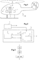
- a rotary wing aircraft 20 is shown.
- This aircraft 20 comprises an inertial unit 1 and a system 10 for analyzing and monitoring parasitic movements of the inertial unit 1 during an alignment phase of the inertial unit 1.
- This system 10 is shown in detail on the figure 2 and comprises a displacement sensor 2 of the aircraft 20 and an estimator 5 provided with a computer 3 and a memory 4.
- the displacement sensor 2 is a GNSS receiver and provides precise measurements of displacement relative to the ground of the aircraft 20, which can be measurements of speed or position, these measurements being based for example on the phase increments of the waves carrying signals transmitted by satellites of at least one GNSS system.
- the memory 4 stores calculation instructions and optionally validation thresholds for the alignment of the inertial unit 1.
- the computer 3 uses these calculation instructions, the displacement measurements and if necessary the validation thresholds for the alignment of the inertial unit 1 in order to implement an analysis and monitoring of parasitic movements of the inertial unit 1, a block diagram of which is shown on the figure 3 .
- the displacement sensor 2 is connected to the estimator 5 in order to provide it with the displacement measurements relative to the ground of the aircraft 20.
- the inertial unit 1 is connected to the system 10 in order to provide it with a start signal t 0 and an end signal t 1 of the alignment phase.
- This method of analyzing and monitoring parasitic movements of the inertial unit 1 during an alignment phase comprises two steps.
- An acquisition 110 of displacement measurements relative to the ground of the aircraft 20 is carried out, by means of the displacement sensor 2, during the alignment phase of the inertial unit 1.
- An estimate 120 of states of a mirror process is also carried out from the observations constituted by the displacement measurements.
- the model of the mirror process has a structure close to that of the model of the process of alignment of the inertial unit 1.
- the model of the mirror process can also be strictly identical to the model of the process of alignment of the inertial unit 1.
- a block diagram of an example of a model of the alignment process of the inertial unit 1 is represented on the figure 4 .
- ⁇ n is the orientation error around the North / South axis
- ⁇ e is the orientation error around the East / West axis
- ⁇ d is the error orientation around a vertical axis
- v n is the speed along the North / South axis
- v e is the speed along the East / West axis.
- This model of the alignment process takes into account the known latitude ⁇ of the aircraft 20 and uses the module of the acceleration of terrestrial gravity g on the one hand, and a vector representing the speed of rotation.
- the symbol ⁇ represents an adder and the symbol represents an integrator. Acceleration errors ⁇ n along the North / South axis and ⁇ e along the East / West axis are also indicated.
- An estimator of the states of the alignment process can then be a Kalman filter comprising these five states.
- one or more additional states may possibly be implemented.
- the latitude ⁇ of the aircraft 20, when it is unknown, can be an additional state of the alignment process and can then be determined by the estimator.
- the model of the mirror process used by the method according to the invention may include a model strictly identical to the model of the alignment process shown in the figure 4 .
- these two models have the same number of states and the same matrices defining the relationships between the states.
- the model of the mirror process can also be simplified or approximated compared to the model of the alignment process.
- the 24-hour mode linked to Earth's rotation has been neglected in particular to establish the mirror process represented in the form of a block diagram on the figure 5 .
- the method according to the invention makes it possible to identify the coefficients of these two polynomial functions.
- the figure 6 presents these measurements of the speed relative to the ground of the aircraft 20 along the North / South axis obtained during the alignment phase, namely between a start t 0 and an end t 1 of a phase of alignment, as well as a representation of the polynomial function corresponding to this speed along the North / South axis.
- the coefficients of these polynomial functions are directly linked to the states of the mirror process.
- the estimation 120 of states of the mirror process consists either in the estimation of these coefficients of each polynomial function, coefficients from which the states are deduced, or in the direct estimation of the states.
- This estimation 120 of the states of the mirror process can be carried out from the observations constituted by the displacement measurements by known mathematical methods such as the non-recursive least squares method or else the recursive least squares method or even by using a filter of Kalman.
- the method according to the invention can use in an additional step 130,140 these error estimates orientation and speeds of the inertial unit 1 due to parasitic movements during this alignment phase.
- this additional step of the method is a comparison 130 of the absolute value of at least one estimate of the orientation errors and of the speeds of the inertial unit 1 with at least one validation threshold and l 'activation of an "alignment not validated" signal if at least one of the thresholds is exceeded.
- this “alignment not validated” signal reveals that the accuracy of the data supplied by the inertial unit 1 is deemed to be insufficient, and that the alignment phase of the inertial unit 1 must for example be restarted, or that the aircraft must be operated in a mode which does not require inertial measurements.
- the additional step of the method consists of a correction 140 of the data supplied by the inertial unit 1.
- This correction 140 uses the estimates of the orientation errors and of the speeds of the inertial unit 1 resulting from parasitic movements during this alignment phase and previously calculated, in order to improve the data provided by the inertial unit 1 and to make them sufficiently precise to be usable.
- the displacement sensor can be arranged outside the system 10 and provide its displacement measurements to the system 10 so that it uses them.
Description
Le domaine général de la présente invention est celui des systèmes de capteurs des aéronefs, et en particulier des centrales inertielles.The general field of the present invention is that of aircraft sensor systems, and in particular inertial units.
La présente invention concerne un système et un procédé d'analyse et de surveillance des mouvements parasites d'une centrale inertielle pendant une phase d'alignement statique de la centrale inertielle.The present invention relates to a system and method for analyzing and monitoring parasitic movements of an inertial unit during a static alignment phase of the inertial unit.
Plus précisément, la présente invention permet l'estimation des erreurs d'orientation et des erreurs de vitesse affectant les mesures de la centrale inertielle résultant de mouvements lors de sa phase d'initialisation statique pendant laquelle :
- la centrale inertielle aligne ses axes sur les axes géographiques et
- la centrale inertielle annule son estimation de vitesse.
- the inertial unit aligns its axes with the geographic axes and
- the inertial unit cancels its speed estimate.
Une centrale inertielle est un instrument utilisé notamment dans le domaine aéronautique, mais peut être installée à bord de tout type de véhicules, à savoir un navire, un sous-marin, un aéronef, un missile ou bien un véhicule spatial. Une centrale inertielle est capable d'intégrer les mouvements qu'elle subit, en particulier des accélérations et des vitesses angulaires, pour fournir des estimations de l'orientation, de la vitesse linéaire ainsi que de la position du véhicule. L'orientation d'un véhicule est définie par exemple par des angles de roulis, de tangage et de cap.An inertial unit is an instrument used in particular in the aeronautical field, but can be installed on board any type of vehicle, namely a ship, a submarine, an aircraft, a missile or even a space vehicle. An inertial unit is capable of integrating the movements it undergoes, in particular accelerations and angular speeds, to provide estimates of the orientation, the linear speed as well as the position of the vehicle. The orientation of a vehicle is defined for example by angles of roll, pitch and heading.
Une centrale inertielle comporte généralement six capteurs, à savoir trois gyromètres permettant de mesurer des vitesses angulaires autour de trois axes, et trois accéléromètres agencés pour mesurer des accélérations le long de ces trois axes. Une centrale inertielle n'a besoin d'aucune information extérieure. Une centrale inertielle exploite exclusivement les mesures fournies par ses capteurs internes de vitesses angulaires et de forces spécifiques pour estimer son orientation, sa vitesse et sa position par intégration au cours du temps des mesures de ses capteurs internes.An inertial unit generally comprises six sensors, namely three gyrometers making it possible to measure angular velocities around three axes, and three accelerometers arranged to measure accelerations along these three axes. An inertial unit does not need any external information. A inertial unit exclusively uses the measurements provided by its internal sensors of angular velocities and specific forces to estimate its orientation, speed and position by integrating over time the measurements of its internal sensors.
Du fait des processus d'intégrations temporelles mis en œuvre, une phase d'initialisation d'une centrale inertielle est indispensable au moment de son démarrage. La phase d'initialisation est généralement réalisée lorsque le véhicule utilisant la centrale inertielle est à l'arrêt, typiquement avant le décollage d'un aéronef.Due to the temporal integration processes implemented, an initialization phase of an inertial unit is essential at the time of its start-up. The initialization phase is generally carried out when the vehicle using the inertial unit is stationary, typically before an aircraft takes off.
Une phase d'initialisation comporte notamment une phase d'alignement durant laquelle sont estimés :
- une direction verticale grâce aux mesures des accéléromètres qui permettent de déterminer la direction de la gravité terrestre et donc de la verticale,
- une direction du Nord géographique grâce aux mesures des gyromètres qui détectent le vecteur de rotation terrestre et donc, moyennant la projection de ce vecteur sur le plan horizontal, la direction du Nord, et
- un vecteur vitesse par rapport au sol.
- a vertical direction thanks to the measurements of the accelerometers which make it possible to determine the direction of the Earth's gravity and therefore of the vertical,
- a direction of the geographic North thanks to the measurements of the gyrometers which detect the vector of terrestrial rotation and therefore, by means of the projection of this vector on the horizontal plane, the direction of the North, and
- a velocity vector with respect to the ground.
Usuellement, une position initiale n'est pas estimée par la centrale inertielle. Elle doit au contraire être insérée, par exemple par l'équipage.Usually, an initial position is not estimated by the inertial unit. On the contrary, it must be inserted, for example by the crew.
Un processus d'alignement typiquement utilisé dans une centrale inertielle vise à faire converger vers des valeurs nulles d'une part les deux angles d'inclinaison d'une plateforme virtuelle calculée par la centrale inertielle et d'autre part un angle de désalignement de cette plateforme virtuelle autour de la direction verticale. Ces processus d'alignement utilisent typiquement un filtre de Kalman.An alignment process typically used in an inertial unit aims at making the two angles of inclination of a virtual platform calculated by the inertial unit converge towards zero values and on the other hand a misalignment angle of this virtual platform around management vertical. These alignment processes typically use a Kalman filter.
Certains processus d'alignement sont basés sur l'hypothèse que le véhicule est immobile et visent donc de surcroît à annuler les deux composantes horizontales de vitesse du véhicule par rapport au sol. On parle alors d'alignement statique. Dans la suite du document, le seul cas de l'alignement statique est traité. Donc, dans un objectif d'allègement du texte, le qualificatif statique est omis, mais à chaque occurrence du terme « alignement », il faut comprendre « alignement statique ».Some alignment processes are based on the assumption that the vehicle is stationary and therefore also aim to cancel the two horizontal components of speed of the vehicle relative to the ground. This is called static alignment. In the remainder of the document, the only case of static alignment is treated. Therefore, in order to lighten the text, the static qualifier is omitted, but at each occurrence of the term "alignment", it is necessary to understand "static alignment".
Mais, pendant le déroulement d'un processus d'alignement, l'aéronef est susceptible de subir des mouvements parasites, tels qu'un remorquage par un véhicule tracteur. L'hypothèse d'immobilité est alors prise en défaut. Il en résulte une mauvaise précision de la centrale inertielle. Les imprécisions résultant de mouvements parasites pendant un alignement peuvent atteindre des valeurs telles qu'elles pourraient ensuite compromettre la sécurité du vol pendant la phase ultérieure de navigation. Pour éviter la pollution de la centrale inertielle, diverses protections sont connues.However, during the course of an alignment process, the aircraft is liable to undergo parasitic movements, such as towing by a towing vehicle. The hypothesis of immobility is then taken in default. This results in poor accuracy of the inertial unit. The inaccuracies resulting from parasitic movements during an alignment can reach such values that they could subsequently compromise flight safety during the subsequent phase of navigation. To protect the inertial unit from pollution, various protections are known.
Dans le but de surveiller l'immobilité de l'aéronef pendant la phase d'alignement de sa centrale inertielle, il est par exemple connu d'analyser l'amplitude du résidu de l'estimateur de Kalman réalisant l'alignement.In order to monitor the immobility of the aircraft during the alignment phase of its inertial unit, it is for example known to analyze the amplitude of the residue of the Kalman estimator performing the alignment.
Ce type de surveillance par le processus d'alignement d'une centrale inertielle détecte de manière satisfaisante des mouvements parasites de fréquence relativement élevée provoqués par exemple par le remorquage de l'aéronef.This type of monitoring by the alignment process of an inertial unit satisfactorily detects parasitic movements of relatively high frequency caused for example by the towing of the aircraft.
Le document
On connait également le document
Enfin, le document
Toutefois, de tels processus d'alignement présentent l'inconvénient de ne pas être efficaces pour la détection de certains mouvements parasites spécifiques, notamment les mouvements lents dont la période coïncide avec la durée de la phase d'alignement complète.However, such alignment processes have the drawback of not being effective in detecting certain specific parasitic movements, in particular slow movements, the period of which coincides with the duration of the complete alignment phase.
Ce problème concerne particulièrement un aéronef à voilure tournante décollant d'une plateforme pétrolière à la mer et pouvant y subir des mouvements très lents et d'une amplitude de plusieurs mètres, dus par exemple au système de stabilisation de la position de la plateforme pétrolière.This problem particularly concerns a rotary wing aircraft taking off from an oil platform at sea and which can undergo very slow movements therein and of an amplitude of several meters, due for example to the system for stabilizing the position of the oil platform.
Il apparait donc que les centrales inertielles et les processus d'alignement statique qu'elles mettent en oeuvre intègrent des moyens de détection de mouvements parasites pendant la phase d'alignement. Cependant, ces moyens de détection ne permettent pas une détection exhaustive de tout type de mouvements parasites susceptibles de perturber la phase d'alignement et, par suite, de générer des erreurs dangereuses dans les données fournies par la centrale inertielle dans sa phase ultérieure de navigation.It therefore appears that the inertial units and the static alignment processes which they employ incorporate means for detecting parasitic movements during the alignment phase. However, these detection means do not allow exhaustive detection of any type of parasitic movements liable to disturb the alignment phase and, consequently, to generate dangerous errors in the data provided by the inertial unit in its subsequent navigation phase. .
La présente invention a pour but de s'affranchir des limitations mentionnées ci-dessus afin de détecter tout type de mouvements parasites subis par une centrale inertielle et susceptible de perturber la phase d'alignement statique. La présente invention peut ensuite inhiber la validation de la phase d'alignement statique afin d'éviter la fourniture de données erronées par la centrale inertielle. La présente invention peut, alternativement, après détection de mouvements parasites et estimation quantifiée de leur effet sur la centrale inertielle, corriger les données erronées fournies par la centrale inertielle afin de les rendre exploitables, à savoir suffisamment précises.The present invention aims to overcome the limitations mentioned above in order to detect any type of parasitic movement undergone by an inertial unit and likely to disturb the static alignment phase. The present invention can then inhibit the validation of the static alignment phase in order to avoid the supply of data. erroneous by the inertial unit. The present invention can, alternatively, after detection of parasitic movements and quantified estimate of their effect on the inertial unit, correct the erroneous data supplied by the inertial unit in order to make them usable, namely sufficiently precise.
Dans ce cadre, la présente invention propose un procédé d'analyse et de surveillance des mouvements parasites d'une centrale inertielle d'un aéronef pendant une phase d'alignement statique de la centrale inertielle.In this context, the present invention provides a method for analyzing and monitoring parasitic movements of an inertial unit of an aircraft during a static alignment phase of the inertial unit.
Ce procédé selon l'invention est remarquable en ce qu'au cours de la phase d'alignement statique de la centrale inertielle, le procédé réalise les deux étapes suivantes :
- une acquisition de mesures de déplacement par rapport au sol de l'aéronef, et
- une estimation d'états d'un processus miroir dont le modèle est voisin du modèle du processus d'alignement de la centrale inertielle, l'estimation des états du processus miroir étant réalisée à partir des observations constituées par les mesures de déplacement.
- acquisition of displacement measurements relative to the ground of the aircraft, and
- an estimation of states of a mirror process whose model is close to the model of the alignment process of the inertial unit, the estimation of the states of the mirror process being carried out from the observations constituted by the displacement measurements.
Ce procédé est particulièrement destiné à être utilisé à bord d'un aéronef, mais il peut être appliqué à tout véhicule utilisant une centrale inertielle.This method is particularly intended for use on board an aircraft, but it can be applied to any vehicle using an inertial unit.
Pour appliquer ce procédé, l'aéronef comporte au moins une centrale inertielle, ainsi qu'un capteur de déplacement permettant de mesurer les déplacements par rapport au sol de l'aéronef et un estimateur d'un processus miroir de structure voisine de la structure du processus d'alignement de la centrale inertielle. Cet estimateur d'un processus miroir voisin du processus d'alignement de la centrale inertielle est configuré pour mettre en œuvre ce procédé d'analyse et de surveillance des mouvements parasites d'une centrale inertielle pendant une phase d'alignement.To apply this method, the aircraft comprises at least one inertial unit, as well as a displacement sensor making it possible to measure the displacements relative to the ground of the aircraft and an estimator of a mirror process of structure close to the structure of the alignment process of the inertial unit. This estimator of a mirror process close to the alignment process of the inertial unit is configured to implement this method for analyzing and monitoring the parasitic movements of an inertial unit during an alignment phase.
Dans ce contexte, on entend par modèles de processus ou processus « voisins » des modèles de processus ou des processus qui sont presque identiques, un modèle d'un processus miroir pouvant notamment être simplifié ou bien approximé, voire simplifié et approximé vis-à-vis du modèle du processus d'alignement. Par exemple, le modèle d'un processus miroir est défini par un jeu d'équations différentielles simplifiées, de degré inférieur ou égal au nombre d'états du modèle du processus d'alignement.In this context, “neighboring” process models or processes are understood to mean almost identical process models or processes, a model of a mirror process that can in particular be simplified or even approximated, or even simplified and approximated with respect to screw the model of the alignment process. For example, the model of a mirror process is defined by a set of simplified differential equations, of degree less than or equal to the number of states of the model of the alignment process.
Le capteur de déplacement est par exemple un capteur de vitesse fournissant des mesures d'une vitesse par rapport au sol
Comme évoqué précédemment, un processus d'alignement d'une centrale inertielle est basé par exemple sur un modèle comportant un ou plusieurs états, notamment les états représentant les erreurs d'orientation et les vitesses, dont l'évolution est gouvernée par une ou plusieurs équations différentielles dont la résolution, au cours de la phase d'alignement, permet la convergence des estimations des états de ce modèle vers des valeurs nulles. Le processus d'alignement peut donc prendre la forme d'un estimateur des erreurs d'orientation et des vitesses.As mentioned above, an alignment process of an inertial unit is based for example on a model comprising one or more states, in particular the states representing orientation errors and speeds, the evolution of which is governed by one or more differential equations whose resolution, during the alignment phase, allows the convergence of the estimates of the states of this model towards zero values. The alignment process can therefore take the form of an estimator of orientation errors and speeds.
À cet estimateur des erreurs d'orientation et des vitesses, un processus de détection de mouvements parasites est généralement associé, typiquement basé sur l'analyse de résidus.In this estimator of orientation errors and speeds, a process of detecting parasitic movements is generally associated, typically based on the analysis of residues.
Malgré les moyens de détection de mouvements parasites mis en place dans la centrale inertielle, éventuellement intégrés au processus d'alignement, des mouvements parasites de la centrale inertielle restent indétectables tout en étant perturbants. Dès lors, l'alignement d'une centrale inertielle de l'art antérieur peut être considéré comme validé alors que dans le même temps les données fournies par la centrale inertielle sont sévèrement erronées et comprennent des erreurs d'orientation et de vitesse excédant le maximum acceptable.Despite the parasite movement detection means installed in the inertial unit, possibly integrated into the alignment process, parasitic movements of the inertial unit remain undetectable while being disturbing. Therefore, the alignment of a inertial unit of the prior art can be considered validated while at the same time the data provided by the inertial unit are severely erroneous and include errors of orientation and speed exceeding the maximum acceptable.
Les mouvements parasites indétectables de manière autonome par le processus de détection des mouvements parasites de la centrale inertielle sont les mouvements dont l'évolution est identique, ou voisine, de l'évolution des états du processus générateur que constitue le solveur des équations différentielles du modèle du processus d'alignement de la centrale inertielle.The parasitic movements undetectable in an autonomous manner by the process of detection of the parasitic movements of the inertial unit are the movements whose evolution is identical, or similar, to the evolution of the states of the generating process that constitutes the solver of the differential equations of the model. of the alignment process of the inertial unit.
En effet, lorsque de tels mouvements reproduisent l'évolution de ces états, les écarts entre respectivement les caractéristiques de ce mouvement et les états estimés par le processus d'alignement sont constamment sensiblement nuls. En conséquence, le processus d'alignement se comporte comme si l'aéronef était immobile malgré la présence de ces mouvements.Indeed, when such movements reproduce the evolution of these states, the differences between the characteristics of this movement respectively and the states estimated by the alignment process are constantly substantially zero. As a result, the alignment process behaves as if the aircraft were stationary despite the presence of these movements.
Dès lors, tout mouvement de la centrale inertielle dont la fonction du temps peut être générée par le solveur de l'équation différentielle de son processus d'alignement, quelle que soit son amplitude, est indiscernable de l'immobilité par les seuls capteurs inertiels et engendre des estimations inertielles d'orientation et de vitesse erronées à l'issue de l'alignement de la centrale inertielle et, par suite, pendant toute la phase de navigation qui succède à la phase d'alignement. L'amplitude de telles erreurs n'est pas bornée.Consequently, any movement of the inertial unit whose time function can be generated by the solver of the differential equation of its alignment process, whatever its amplitude, is indistinguishable from immobility by the inertial sensors only and generates erroneous inertial orientation and speed estimates at the end of the alignment of the inertial unit and, consequently, during the entire navigation phase which follows the alignment phase. The magnitude of such errors is not limited.
Pour remédier à ce problème, le procédé selon l'invention utilise avantageusement un processus miroir dont le modèle est voisin du modèle de la propagation des erreurs dans le processus d'alignement de la centrale inertielle. Le procédé selon l'invention permet alors de réaliser une estimation des états de ce processus miroir à partir des observations constituées par les mesures de déplacement. Ces estimations d'états constituent des estimations des erreurs d'orientation et de vitesse affectant les données fournies par la centrale inertielle à la fin de la phase d'alignement.To remedy this problem, the method according to the invention advantageously uses a mirror process whose model is close to the model of the propagation of errors in the alignment process of the inertial unit. The method according to the invention then makes it possible to carry out an estimation of the states of this mirror process from observations made up by the displacement measurements. These state estimates constitute estimates of the orientation and speed errors affecting the data supplied by the inertial unit at the end of the alignment phase.
Si le modèle de ce processus miroir était identique au modèle du processus d'alignement de la centrale inertielle, les équations différentielles gouvernant l'évolution des états du modèle du processus miroir et du modèle du processus d'alignement seraient alors les mêmes, et notamment les deux modèles ont le même nombre d'états.If the model of this mirror process were identical to the model of the alignment process of the inertial unit, the differential equations governing the evolution of the states of the model of the mirror process and of the model of the alignment process would then be the same, and in particular both models have the same number of states.
Selon l'invention, le modèle du processus miroir est simplifié vis-à-vis du modèle du processus d'alignement. Notamment, certains états du processus d'alignement peuvent avoir un impact très faible sur le comportement global du modèle et peuvent donc être négligés et ne pas être incorporés au processus miroir.According to the invention, the model of the mirror process is simplified with respect to the model of the alignment process. In particular, certain states of the alignment process can have a very small impact on the overall behavior of the model and can therefore be neglected and not be incorporated into the mirror process.
Par exemple, lorsque les mesures de déplacement sont des mesures de vitesse par rapport au sol
Dans un mode particulier de réalisation de l'invention, on utilise ce processus miroir en boucle ouverte. Ces deux sorties du processus miroir évoluent alors selon des fonctions polynômiales du temps, d'une part une fonction polynômiale du deuxième degré pour la composante Nord/Sud de la vitesse et d'autre part une fonction polynômiale du premier degré pour la composante Est/Ouest de la vitesse. Dans ce mode particulier de réalisation, l'estimation du processus miroir consiste à calculer :
- i) une parabole, correspondant à la fonction polynômiale du deuxième degré, la plus proche des composantes Nord/Sud des mesures de la vitesse par rapport au sol, et
- ii) une droite, correspondant à la fonction polynômiale du premier degré, la plus proche des composantes Est/Ouest des mesures de la vitesse par rapport au sol.
- i) a parabola, corresponding to the polynomial function of the second degree, closest to the North / South components of the measurements of the speed relative to the ground, and
- ii) a straight line, corresponding to the polynomial function of the first degree, closest to the East / West components of the velocity measurements relative to the ground.
Ce calcul des fonctions polynômiales les plus proches peut être réalisé par la méthode des moindres carrés, non-récursifs ou récursifs.This computation of the nearest polynomial functions can be carried out by the method of least squares, non-recursive or recursive.
Dans un autre mode de réalisation de l'invention, cette estimation des états du processus miroir consiste par exemple en un filtrage de Kalman dont les états sont ceux du processus miroir et dont les observations sont les mesures de déplacement par rapport au sol.In another embodiment of the invention, this estimation of the states of the mirror process consists for example of a Kalman filtering whose states are those of the mirror process and whose observations are the displacement measurements relative to the ground.
Dans le cas de la méthode des moindres carrés non-récursifs, l'acquisition des mesures de déplacement de l'aéronef et l'estimation d'états du processus miroir sont réalisées de façon séquentielle. Dans le cas de la méthode des moindres carrés récursifs et d'un filtrage de Kalman, l'acquisition des mesures de déplacement de l'aéronef et l'estimation d'états du processus miroir sont réalisées de façon simultanée.In the case of the non-recursive least squares method, the acquisition of the displacement measurements of the aircraft and the estimation of states of the mirror process are carried out sequentially. In the case of the recursive least squares method and of a Kalman filtering, the acquisition of the measurements of displacement of the aircraft and the estimation of states of the mirror process are carried out simultaneously.
Par ailleurs, dans le cadre de variantes, le procédé selon l'invention peut comporter une étape supplémentaire.Furthermore, in the context of variants, the method according to the invention may include an additional step.
Ainsi, selon une première variante, l'étape supplémentaire du procédé est avantageusement une comparaison de la valeur absolue d'au moins une estimation d'un des états avec au moins un seuil de validation afin de valider ou non l'alignement de la centrale inertielle.Thus, according to a first variant, the additional step of the method is advantageously a comparison of the absolute value of at least one estimate of one of the states with at least one validation threshold in order to validate or not the alignment of the central unit inertial.
Par exemple, selon cette première variante, des seuils de validation de l'alignement sont définis. Ces seuils de validation sont généralement définis en phase de développement du système et du procédé d'analyse et de surveillance selon l'invention. Les valeurs de ces seuils de validation sont choisies en fonction de la précision attendue de la centrale inertielle. Chaque seuil de validation correspond respectivement à un des états estimés, ces états estimés correspondant respectivement aux erreurs d'orientation et de vitesse dues aux mouvements parasites pendant la phase d'alignement et affectant les données fournies par la centrale inertielle à l'issue de la phase d'alignement.For example, according to this first variant, alignment validation thresholds are defined. These validation thresholds are generally defined during the development phase of the system and of the analysis and monitoring method according to the invention. The values of these validation thresholds are chosen according to the expected accuracy of the inertial unit. Each validation threshold corresponds respectively to one of the estimated states, these estimated states corresponding respectively to orientation and speed errors due to parasitic movements during the alignment phase and affecting the data supplied by the inertial unit at the end of the alignment phase.
De la sorte, au cours de cette comparaison, la valeur absolue d'au moins une estimation des états est comparée au seuil de validation correspondant, et un signal « alignement non validé » est activé dès que la valeur absolue d'une estimation d'un état est supérieure au seuil de validation correspondant. Le procédé peut avantageusement permettre de se limiter à la comparaison des estimations des états influant le plus sur la performance de la centrale inertielle.In this way, during this comparison, the absolute value of at least one estimate of the states is compared with the corresponding validation threshold, and an “alignment not validated” signal is activated as soon as the absolute value of an estimate of a state is greater than the corresponding validation threshold. The method can advantageously make it possible to limit oneself to the comparison of the estimates of the states most influencing the performance of the inertial unit.
De préférence, les valeurs absolues individuelles des estimations des états sont comparées respectivement aux seuils de validation correspondants afin de vérifier la qualité de l'alignement de la centrale inertielle.Preferably, the individual absolute values of the estimates of the states are compared respectively with the corresponding validation thresholds in order to check the quality of the alignment of the inertial unit.
Selon un autre exemple de cette première variante, au cours de cette comparaison, au moins deux estimations d'états sont combinées pour former une combinaison d'états estimés et un signal « alignement non validé » est activé lorsque cette combinaison d'états estimés est supérieure à un seuil global. Le seuil global est une constante prédéterminée correspondant à une valeur maximale d'erreur acceptable et choisie en fonction de la précision attendue de la centrale inertielle.According to another example of this first variant, during this comparison, at least two estimates of states are combined to form a combination of estimated states and an “alignment not validated” signal is activated when this combination of estimated states is greater than an overall threshold. The global threshold is a predetermined constant corresponding to a maximum acceptable error value and chosen as a function of the expected precision of the inertial unit.
Une telle combinaison d'états estimés permet notamment de privilégier la surveillance de certains états en affectant un poids à une estimation d'un état supérieur au poids d'une estimation d'un autre d'état. La combinaison d'états estimés est par exemple égale à une somme quadratique pondérée d'au moins deux estimations d'états.Such a combination of estimated states makes it possible in particular to privilege the monitoring of certain states by assigning a weight to an estimate of a state greater than the weight of an estimate of another state. The combination of estimated states is, for example, equal to a weighted quadratic sum of at least two state estimates.
Selon une seconde variante du procédé selon l'invention, le procédé peut utiliser les estimations d'états non pas pour valider ou non l'alignement, mais pour corriger les données fournies par la centrale inertielle afin que les données après correction soient conformes à la précision attendue de la centrale inertielle et soient, de ce fait, exploitables par les systèmes de l'aéronef dans lesquels la centrale inertielle est installée.According to a second variant of the method according to the invention, the method can use the state estimates not to validate or not the alignment, but to correct the data supplied by the inertial unit so that the data after correction comply with the accuracy expected from the inertial unit and can therefore be used by the aircraft systems in which the inertial unit is installed.
Dès lors, l'étape supplémentaire du procédé selon cette seconde variante consiste avantageusement en une correction des données fournies par la centrale inertielle permettant de rendre ces données inertielles exploitables, cette correction étant calculée à partir des états estimés par le processus miroir. Par exemple, chaque estimation d'un état du processus miroir est utilisée en tant que valeur initiale d'un processus estimateur des erreurs de la centrale inertielle en navigation. Ce processus estimateur d'erreurs de la centrale inertielle en navigation est ensuite entretenu pendant toute la durée de la phase de navigation de la centrale inertielle consécutive à la phase d'alignement. Enfin, les estimations d'erreurs ainsi entretenues sont retranchées des données fournies par la centrale inertielle.Consequently, the additional step of the method according to this second variant advantageously consists of a correction of the data supplied by the inertial unit making it possible to make these inertial data exploitable, this correction being calculated from the states estimated by the mirror process. For example, each estimate of a state of the mirror process is used as the initial value of a process estimating the errors of the inertial unit in navigation. This process of estimating errors of the inertial unit during navigation is then maintained throughout the duration of the navigation phase of the unit. inertial following the alignment phase. Finally, the error estimates thus maintained are deducted from the data provided by the inertial unit.
En outre, pour bien estimer les paramètres des mouvements parasites de la centrale inertielle et en déduire les erreurs résultantes de la centrale inertielle avec précision, le procédé selon l'invention doit exploiter de préférence des mesures du déplacement elles-mêmes précises. Ces mesures de déplacement sont avantageusement fournies par exemple par un récepteur GNSS exploitant les incréments de phase des ondes porteuses des signaux émis par des satellites. En effet, le bruit de mesure qui en résulte, notamment pour les mesures de vitesse, est bien plus faible que celui des méthodes utilisées traditionnellement telles que celles basées sur la dérivée de la position ou sur l'observation de l'effet Doppler sur les dites porteuses. La mise en œuvre de cette technique est par exemple décrite dans le magazine
Pour des mesures de vitesse, la précision qui résulte de la technique des incréments de phase des ondes porteuses est de l'ordre de quelques millimètres par seconde en utilisant exclusivement les signaux issus de satellites. Pour des mesures de position, la précision peut être de l'ordre de quelques millimètres mais l'obtention d'une telle précision nécessite, en plus des signaux issus de satellites, une station fixe au sol communiquant avec l'aéronef.For speed measurements, the precision resulting from the phase increment technique of the carrier waves is of the order of a few millimeters per second using exclusively the signals from satellites. For position measurements, the precision may be of the order of a few millimeters, but obtaining such precision requires, in addition to the signals from satellites, a fixed station on the ground communicating with the aircraft.
De la sorte, le procédé selon l'invention permet de réaliser un alignement de la centrale inertielle surveillé par l'intermédiaire du capteur de déplacement. Les mesures de déplacement fournies par le capteur de déplacement ne sont en effet pas mélangées ni combinées aux données délivrées par la centrale inertielle.In this way, the method according to the invention makes it possible to achieve alignment of the inertial unit monitored by means of the displacement sensor. The displacement measurements provided by the displacement sensor are neither mixed nor combined with the data delivered by the inertial unit.
En conséquence, si le capteur de déplacement fournit des mesures corrompues, cela se traduira par l'émission d'une fausse alarme correspondant à un « alignement bougé », mais, en aucun cas, les données fournies par la centrale inertielle ne seront corrompue par ces mesures de déplacement.Consequently, if the displacement sensor provides corrupted measurements, this will result in the emission of a false alarm corresponding to a “shake alignment”, but, in no case, the data provided by the inertial unit will be corrupted by these displacement measurements.
La présente invention a aussi pour objet un système d'analyse et de surveillance des mouvements parasites d'une centrale inertielle d'un aéronef pendant une phase d'alignement. Un tel système d'analyse et de surveillance des mouvements parasites d'une centrale inertielle pendant une phase d'alignement comporte un capteur de déplacement de l'aéronef fournissant des mesures de déplacement par rapport au sol de l'aéronef ainsi qu'un estimateur d'un processus miroir dont la structure est voisine de la structure du processus d'alignement de la centrale inertielle. Cet estimateur est muni d'au moins un calculateur ou processeur et d'au moins une mémoire stockant notamment des instructions de calcul et éventuellement des seuils de validation de l'alignement de la centrale inertielle.The present invention also relates to a system for analyzing and monitoring parasitic movements of an inertial unit of an aircraft during an alignment phase. Such a system for analyzing and monitoring parasitic movements of an inertial unit during an alignment phase comprises an aircraft displacement sensor providing displacement measurements relative to the ground of the aircraft as well as an estimator of a mirror process whose structure is close to the structure of the alignment process of the inertial unit. This estimator is provided with at least one computer or processor and at least one memory storing in particular calculation instructions and possibly thresholds for validating the alignment of the inertial unit.
L'estimateur est configuré pour mettre en œuvre le procédé précédemment évoqué et pour permettre d'estimer des états du processus miroir à partir des observations constituées par les mesures de déplacement fournies par le capteur de déplacement.The estimator is configured to implement the previously mentioned method and to allow states of the mirror process to be estimated from the observations formed by the displacement measurements provided by the displacement sensor.
L'invention et ses avantages apparaîtront avec plus de détails dans le cadre de la description qui suit avec des exemples de réalisation donnés à titre illustratif en référence aux figures annexées qui représentent :
- la
figure 1 , un aéronef muni d'un système d'analyse et de surveillance des mouvements parasites d'une centrale inertielle, - la
figure 2 , le système d'analyse et de surveillance des mouvements parasites d'une centrale inertielle, - la
figure 3 , un schéma synoptique d'un procédé d'analyse et de surveillance des mouvements parasites d'une centrale inertielle, - la
figure 4 , une représentation d'un modèle d'un processus d'alignement d'une centrale inertielle, - la
figure 5 , une représentation d'un processus miroir, et - la
figure 6 , une représentation des mesures de déplacement de l'aéronef.
- the
figure 1 , an aircraft fitted with a system for analyzing and monitoring parasitic movements of an inertial unit, - the
figure 2 , the system for analyzing and monitoring parasitic movements of an inertial unit, - the
figure 3 , a block diagram of a process for analyzing and monitoring parasitic movements of an inertial unit, - the
figure 4 , a representation of a model of an alignment process of an inertial unit, - the
figure 5 , a representation of a mirror process, and - the
figure 6 , a representation of the displacement measurements of the aircraft.
Les éléments présents dans plusieurs figures distinctes sont affectés d'une seule et même référence.The elements present in several separate figures are assigned a single reference.
Sur la
Le capteur de déplacement 2 est un récepteur GNSS et fournit des mesures précises de déplacement par rapport au sol de l'aéronef 20, qui peuvent être des mesures de vitesse ou de position, ces mesures étant basées par exemple sur les incréments de phase des ondes porteuses des signaux émis par les satellites d'au moins un système GNSS. La mémoire 4 stocke des instructions de calcul et éventuellement des seuils de validation de l'alignement de la centrale inertielle 1. Le calculateur 3 utilise ces instructions de calcul, les mesures de déplacement et le cas échéant les seuils de validation de l'alignement de la centrale inertielle 1 afin de mettre en œuvre un procédé d'analyse et de surveillance des mouvements parasites de la centrale inertielle 1 dont un schéma synoptique est représenté sur la
Le capteur de déplacement 2 est relié à l'estimateur 5 afin de lui fournir les mesures de déplacement par rapport au sol de l'aéronef 20. La centrale inertielle 1 est reliée au système 10 afin de lui fournir un signal de début t0 et un signal de fin t1 de la phase d'alignement.The
Ce procédé d'analyse et de surveillance des mouvements parasites de la centrale inertielle 1 pendant une phase d'alignement comporte deux étapes.This method of analyzing and monitoring parasitic movements of the
Une acquisition 110 de mesures de déplacement par rapport au sol de l'aéronef 20 est réalisée, par l'intermédiaire du capteur de déplacement 2, pendant la phase d'alignement de la centrale inertielle 1.An
Une estimation 120 d'états d'un processus miroir est également réalisée à partir des observations constituées par les mesures de déplacement. Le modèle du processus miroir a une structure voisine de celle du modèle du processus d'alignement de la centrale inertielle 1.An
Le modèle du processus miroir peut également être rigoureusement identique au modèle du processus d'alignement de la centrale inertielle 1.The model of the mirror process can also be strictly identical to the model of the process of alignment of the
Pendant la phase d'alignement, le processus d'alignement vise à estimer la direction verticale, en annulant les deux angles d'inclinaison de la centrale inertielle 1 autour des axes géographiques Nord/Sud et Est/Ouest, à estimer la direction du Nord en annulant l'angle de désalignement de la centrale inertielle 1 autour de l'axe vertical, et enfin à estimer les composantes de la vitesse par rapport au sol de l'aéronef 20. Le processus d'alignement d'une centrale inertielle 1 est par exemple un système à cinq états, qui sont :
- i) les trois écarts angulaires entre d'une part les axes de la plateforme virtuelle de centrale inertielle 1 et d'autre part la direction des axes géographiques locaux,
- ii) les deux composantes horizontales de vitesse par rapport au sol de la centrale inertielle 1.
- i) the three angular differences between on the one hand the axes of the virtual platform of
inertial unit 1 and on the other hand the direction of the local geographical axes, - ii) the two horizontal components of speed relative to the ground of the
inertial unit 1.
Si la centrale inertielle 1 est réellement immobile lors de la phase d'alignement, ces écarts angulaires et ces composantes horizontales de vitesse convergent vers des valeurs nulles et la centrale inertielle 1 se trouve correctement initialisée.If the
Un schéma-bloc d'un exemple d'un modèle du processus d'alignement de la centrale inertielle 1 est représenté sur la
Ce modèle du processus d'alignement prend en compte la latitude connue φ de l'aéronef 20 et utilise le module de l'accélération de la pesanteur terrestre g d'une part, et un vecteur représentant la vitesse de rotation ![]()
![]()
Sur cette ![]()
![]()
Un estimateur des états du processus d'alignement peut alors être un filtre de Kalman comportant ces cinq états. Dans d'autres exemples de processus d'alignement, un ou plusieurs états supplémentaires peuvent éventuellement être mis en œuvre. Par exemple, la latitude φ de l'aéronef 20, lorsqu'elle est inconnue, peut être un état supplémentaire du processus d'alignement et peut alors être déterminée par l'estimateur.An estimator of the states of the alignment process can then be a Kalman filter comprising these five states. In other examples of alignment processes, one or more additional states may possibly be implemented. For example, the latitude φ of the
Le modèle du processus miroir utilisé par le procédé selon l'invention peut comporter un modèle rigoureusement identique au modèle du processus d'alignement représenté sur la
Le modèle du processus miroir peut également être simplifié ou bien approximé vis-à-vis du modèle du processus d'alignement. Par exemple, le mode à 24 heures lié à la rotation terrestre a notamment été négligé pour établir le processus miroir représenté sous la forme d'un schéma-bloc sur la
Quand il fonctionne en boucle ouverte, le modèle de ce processus miroir de la ![]()
![]()
![]()
![]()
De ces équations, on déduit que les mouvements ayant un effet sur la précision de l'alignement de la centrale inertielle 1 sont les mouvements consistant en :
- i) une rampe de vitesse le long de l'axe Est/Ouest, ladite rampe étant définie par les coefficients θ n0 et V e0 , et
- ii) une parabole de vitesse le long de l'axe Nord/Sud, ladite parabole étant définie par les coefficients θ d0, θn0, θe0 et V n0.
- i) a speed ramp along the east / west axis, said ramp being defined by the coefficients θ n 0 and V e 0 , and
- ii) a speed parabola along the North / South axis, said parabola being defined by the coefficients θ d0 , θ n0 , θ e0 and V n 0 .
En utilisant les mesures de déplacement, qui sont dans ce cas des mesures de la vitesse par rapport au sol de l'aéronef 20 pendant la phase d'alignement de la centrale inertielle 1, le procédé selon l'invention permet d'identifier les coefficients de ces deux fonctions polynômiales. La
Les coefficients de ces fonctions polynômiales sont directement liés aux états du processus miroir. L'estimation 120 d'états du processus miroir consiste soit en l'estimation de ces coefficients de chaque fonction polynômiale, coefficients à partir desquels on déduit les états, soit en l'estimation directe des états. Cette estimation 120 des états du processus miroir peut être effectuée à partir des observations constituées par les mesures de déplacement par des méthodes mathématiques connues telles que la méthode des moindres carrés non récursifs ou bien la méthode des moindres carrés récursifs ou encore en utilisant un filtre de Kalman.The coefficients of these polynomial functions are directly linked to the states of the mirror process. The
Le procédé selon l'invention peut utiliser au cours d'une étape supplémentaire 130,140 ces estimations des erreurs d'orientation et des vitesses de la centrale inertielle 1 due aux mouvements parasites lors de cette phase d'alignement.The method according to the invention can use in an additional step 130,140 these error estimates orientation and speeds of the
Selon une première variante de l'invention, cette étape supplémentaire du procédé est une comparaison 130 de la valeur absolue d'au moins une estimation des erreurs d'orientation et des vitesses de la centrale inertielle 1 avec au moins un seuil de validation et l'activation d'un signal « alignement non validé » si au moins un des seuils est dépassé.According to a first variant of the invention, this additional step of the method is a
L'activation de ce signal « alignement non validé » révèle alors que la précision des données fournies par la centrale inertielle 1 est réputée insuffisante, et que la phase d'alignement de la centrale inertielle 1 doit par exemple être relancée, ou que l'aéronef doit être opéré dans un mode ne requérant pas les mesures inertielles.The activation of this “alignment not validated” signal then reveals that the accuracy of the data supplied by the
Selon une seconde variante de l'invention, l'étape supplémentaire du procédé consiste en une correction 140 des données fournies par la centrale inertielle 1. Cette correction 140 utilise les estimations des erreurs d'orientation et des vitesses de la centrale inertielle 1 résultant de mouvements parasites pendant cette phase d'alignement et précédemment calculées, afin d'améliorer les données fournies par la centrale inertielle 1 et de les rendre suffisamment précises pour être exploitables.According to a second variant of the invention, the additional step of the method consists of a
Naturellement, la présente invention est sujette à de nombreuses variations quant à sa mise en œuvre. Bien que plusieurs modes de réalisation aient été décrits, on comprend bien qu'il n'est pas concevable d'identifier de manière exhaustive tous les modes possibles.Naturally, the present invention is subject to numerous variations as to its implementation. Although several embodiments have been described, it is understood that it is not conceivable to identify exhaustively all the possible modes.
Par exemple le capteur de déplacement peut être agencé à l'extérieur du système 10 et fournir ses mesures de déplacement au système 10 afin qu'il les utilise.For example, the displacement sensor can be arranged outside the
Il est bien sûr également envisageable de remplacer un moyen décrit par un moyen équivalent sans sortir du cadre de la présente invention.It is of course also conceivable to replace a means described by an equivalent means without departing from the scope of the present invention.
Claims (14)
- Method for analysing and monitoring interfering movements of an inertial unit (1) of an aircraft (20) during a static alignment phase of said inertial unit (1), such that, during the said static alignment phase of said inertial unit (1), said method carries out the following steps:- an acquisition (110) of displacement measurements of said aircraft (20) with respect to the ground, provided by a displacement sensor of the aircraft (20), and- an estimate (120) of the states of a mirror process in which the model is simplified and/or approximated with respect to the model of a static alignment process of said inertial unit (1) used during the static alignment phase, said estimate of said states of said mirror process being carried out using observations consisting of said displacement measurements.
- Method according to claim 1, characterised in that validation thresholds of said static alignment having been defined previously for said static alignment phase of said inertial unit (1), each validation threshold corresponding respectively to one of said estimated states, said method comprises an extra comparison step (130) of comparing the absolute value of at least one estimate of one of said states with at least one validation threshold.
- Method according to claim 2, characterised in that during said extra comparison step (130), the absolute value of at least one estimate of said states is compared with the corresponding validation threshold, and a "non-validated alignment" signal is activated as soon as the absolute value of an estimate of a state is greater than said corresponding validation threshold.
- Method according to claim 2, characterised in that during said extra comparison step (130), at least two estimates of said states are combined so as to form a combination of estimated states and a "non-validated alignment" signal is activated when said combination of estimated states is greater than an overall threshold.
- Method according to claim 4, characterised in that said combination of estimated states is equal to a weighted quadratic sum of at least two estimates of said states.
- Method according to claim 1, characterised in that said method comprises an extra correction step (140) of the data provided by said inertial unit (1), the extra correction step (140) using estimates of orientation errors and velocities of said inertial unit (1) resulting from unwanted movements during said alignment phase, so as to make the data supplied by said inertial unit (1) useable.
- Method according to claim 6, characterised in that during said extra correction step (140), said correction is calculated from said estimated states, each estimated state being used as an initial value of an estimation process of the errors of said inertial unit (1), said estimation process of errors being maintained throughout the duration of a navigation phase of said inertial unit (1) following said alignment phase and said estimates of said maintained errors being subtracted from said data provided by said inertial unit (1).
- Method according to any one of claims 1 to 7, characterised in that during said acquisition (110), said displacement measurements with respect to the ground of said aircraft (20) are measurements of a velocity with respect to the ground (
vg ,) of said aircraft (20). - Method according to any one of claims 1 to 7, characterised in that during said acquisition (110), said displacement measurements with respect to the ground of said aircraft (20) are measurements of a position with respect to the ground (
xg ) of said aircraft (20). - Method according to any one of claims 1 to 9, characterised in that said estimate (120) of states of said mirror process consists in estimating the coefficients of at least one polynomial function of the time close to said displacement measurements.
- Method according to claim 10, characterised in that since said displacement measurements are measurements of velocity with respect to the ground
vg , said model of said mirror process being capable of generating a second-degree polynomial function of the time for the north/south component of velocity with respect to the ground and a first-degree polynomial function of the time for the east/west component of velocity with respect to the ground. - Method according to either one of claims 10 or 11, characterised in that said estimate (120) of states of said mirror process is carried out by the method of least squares, in which the coefficients to be identified are those of said at least one polynomial function of the time.
- Method according to any one of claims 1 to 11, characterised in that said estimate (120) of states of said mirror processes consists in a Kalman filtering in which the states are those of said mirror process and in which the observations are in said displacement measurements with respect to the ground.
- System (10) for analysing and monitoring interfering movements of an inertial unit (1) during a static alignment phase, said system (10) comprising a displacement sensor (2) of an aircraft (20) providing displacement measurements of said aircraft (20) with respect to the ground, such that said system (10) comprises an estimator (5) of a simplified and/or approximated mirror process with respect to the static alignment process of said inertial unit (1), said estimator (5) being configured so as to implement the method according to claims 1 to 13 and provided with at least one calculator (3) and at least one memory (4) storing validation thresholds of said static alignment of said inertial unit (1) and calculation instructions, said estimator (5) enabling states of said mirror process to be estimated, in which a model is simplified and/or approximated with regard to the model of said static alignment process of said inertial unit (1), said estimate (120) of said states of said mirror process being carried out from observations consisting of displacement measurements provided by said displacement sensor (2).
Applications Claiming Priority (1)
| Application Number | Priority Date | Filing Date | Title |
|---|---|---|---|
| FR1770355A FR3065067B1 (en) | 2017-04-07 | 2017-04-07 | SYSTEM AND METHOD FOR ANALYZING AND MONITORING PARASITIC MOVEMENTS OF AN INERTIAL POWER PLANT DURING A STATIC ALIGNMENT PHASE. |
Publications (2)
| Publication Number | Publication Date |
|---|---|
| EP3385677A1 EP3385677A1 (en) | 2018-10-10 |
| EP3385677B1 true EP3385677B1 (en) | 2020-01-22 |
Family
ID=59521143
Family Applications (1)
| Application Number | Title | Priority Date | Filing Date |
|---|---|---|---|
| EP18164005.3A Active EP3385677B1 (en) | 2017-04-07 | 2018-03-26 | A system and a method of analyzing and monitoring interfering movements of an inertial unit during a stage of static alignment |
Country Status (3)
| Country | Link |
|---|---|
| US (2) | US11022462B2 (en) |
| EP (1) | EP3385677B1 (en) |
| FR (1) | FR3065067B1 (en) |
Families Citing this family (3)
| Publication number | Priority date | Publication date | Assignee | Title |
|---|---|---|---|---|
| FR3065067B1 (en) * | 2017-04-07 | 2020-02-28 | Airbus Helicopters | SYSTEM AND METHOD FOR ANALYZING AND MONITORING PARASITIC MOVEMENTS OF AN INERTIAL POWER PLANT DURING A STATIC ALIGNMENT PHASE. |
| US11193772B1 (en) * | 2018-03-09 | 2021-12-07 | Greensea Systems, Inc. | Autonomous merit-based heading alignment and initialization methods for inertial navigation systems, and apparatuses and software incorporating same |
| CN111308457B (en) * | 2019-12-11 | 2021-11-16 | 成都汇蓉国科微系统技术有限公司 | Method, system and storage medium for north finding of pulse Doppler radar |
Citations (3)
| Publication number | Priority date | Publication date | Assignee | Title |
|---|---|---|---|---|
| US20100161223A1 (en) * | 2008-12-22 | 2010-06-24 | Sagem Defense Securite | Method of determining a heading in the geographical north direction by means of an inertial unit |
| WO2011045032A1 (en) * | 2009-10-15 | 2011-04-21 | Sagem Defense Securite | A method of detecting parasitic movements while aligning an inertial unit |
| EP2330382A2 (en) * | 2009-12-03 | 2011-06-08 | Honeywell International Inc. | Method and system for latitude adaptive navigation quality estimation |
Family Cites Families (8)
| Publication number | Priority date | Publication date | Assignee | Title |
|---|---|---|---|---|
| US4032759A (en) * | 1975-10-24 | 1977-06-28 | The Singer Company | Shipboard reference for an aircraft navigation system |
| US4254465A (en) * | 1978-08-03 | 1981-03-03 | Dynamic Sciences International, Inc. | Strap-down attitude and heading reference system |
| FR2668447B1 (en) * | 1990-10-29 | 1993-01-22 | Aerospatiale | SYSTEM FOR ALIGNING THE INERTIAL CONTROL UNIT OF A VEHICLE CARRYING ON THAT OF A CARRIER VEHICLE. |
| US7606665B2 (en) * | 2003-08-29 | 2009-10-20 | Honeywell International Inc. | System and method for employing an aided-alignment mode to align an inertial reference system |
| US7512493B2 (en) * | 2006-05-31 | 2009-03-31 | Honeywell International Inc. | High speed gyrocompass alignment via multiple Kalman filter based hypothesis testing |
| FR2951935B1 (en) | 2009-11-03 | 2012-02-17 | Sedatelec | MOXIBUSTION PROCESSING DEVICE |
| US20110313614A1 (en) * | 2010-06-21 | 2011-12-22 | Hinnant Jr Harris O | Integrated aeroelasticity measurement for vehicle health management |
| FR3065067B1 (en) * | 2017-04-07 | 2020-02-28 | Airbus Helicopters | SYSTEM AND METHOD FOR ANALYZING AND MONITORING PARASITIC MOVEMENTS OF AN INERTIAL POWER PLANT DURING A STATIC ALIGNMENT PHASE. |
-
2017
- 2017-04-07 FR FR1770355A patent/FR3065067B1/en not_active Expired - Fee Related
-
2018
- 2018-03-26 EP EP18164005.3A patent/EP3385677B1/en active Active
- 2018-04-04 US US15/945,525 patent/US11022462B2/en active Active
-
2021
- 2021-04-12 US US17/228,080 patent/US11454517B2/en active Active
Patent Citations (3)
| Publication number | Priority date | Publication date | Assignee | Title |
|---|---|---|---|---|
| US20100161223A1 (en) * | 2008-12-22 | 2010-06-24 | Sagem Defense Securite | Method of determining a heading in the geographical north direction by means of an inertial unit |
| WO2011045032A1 (en) * | 2009-10-15 | 2011-04-21 | Sagem Defense Securite | A method of detecting parasitic movements while aligning an inertial unit |
| EP2330382A2 (en) * | 2009-12-03 | 2011-06-08 | Honeywell International Inc. | Method and system for latitude adaptive navigation quality estimation |
Also Published As
| Publication number | Publication date |
|---|---|
| FR3065067A1 (en) | 2018-10-12 |
| US20180292232A1 (en) | 2018-10-11 |
| US11022462B2 (en) | 2021-06-01 |
| EP3385677A1 (en) | 2018-10-10 |
| FR3065067B1 (en) | 2020-02-28 |
| US11454517B2 (en) | 2022-09-27 |
| US20210302196A1 (en) | 2021-09-30 |
Similar Documents
| Publication | Publication Date | Title |
|---|---|---|
| EP3623758B1 (en) | Positioning system, and associated method for positioning | |
| EP1801539B1 (en) | Closed loop hybridisation device with surveillance of measurement integrity | |
| EP2299287B1 (en) | Hybrid system and apparatus for calculating the position and monitoring the integrity | |
| EP2069818B1 (en) | Method and device for mojnitoringthe integrity of information provided by a hybrid ins/gnss system | |
| EP3385677B1 (en) | A system and a method of analyzing and monitoring interfering movements of an inertial unit during a stage of static alignment | |
| EP2374022B1 (en) | Integrated closed-loop hybridization device built in by construction | |
| EP2495530B1 (en) | Method and system for determining the attitude of an aircraft by multi-axial accelerometric measurements | |
| EP2541200B1 (en) | Navigation device and method including a plurality of hybrid inertial navigation systems | |
| WO2012013525A1 (en) | Method for determining a protection space in the event of two simultaneous satellite failures | |
| EP2449409B1 (en) | Method for determining the position of a mobile body at a given instant and for monitoring the integrity of the position of said mobile body | |
| FR2943869A1 (en) | METHOD AND DEVICE FOR DETECTING AND EXCLUDING SATELLITE FAILURES IN AN INS / GNSS HYBRID SYSTEM | |
| EP3454010A1 (en) | Method for compensating a magnetic field, associated device and computer program | |
| EP3869155A1 (en) | Method for determining the position and orientation of a vehicle | |
| FR3023918A1 (en) | METHOD FOR ESTIMATING THE SPEED OF AN AIRCRAFT IN RELATION TO THE SURROUNDING AIR, AND ASSOCIATED SYSTEM | |
| EP3006897A1 (en) | Method for navigating a vehicle, navigation device and vehicle for carrying out said method | |
| EP3896398B1 (en) | Method for identifying a static phase of a vehicle | |
| EP2366116A1 (en) | Hybridization device with segregated kalman filters | |
| EP1956386A1 (en) | Method for determining the position of a moving body and a protection limit around this position | |
| EP4100696A1 (en) | Navigation assistance method for a mobile carrier | |
| EP3374800A1 (en) | Method for detecting parasitic movements during static alignment of an inertial measurement unit, and associated detection device | |
| EP3726183A1 (en) | Method for determining the position and orientation of a vehicle | |
| FR2802732A1 (en) | Receiver satellite position/inertial center hybrid combination method having navigation calculation speed/position inputs and inertial reference synthesized unit compared with best information kalman filter/navigation passed. | |
| FR3023919A1 (en) | METHOD OF ESTIMATING THE SPEED OF AN AIRCRAFT IN RELATION TO THE SURROUNDING AIR AND ASSOCIATED SYSTEM | |
| FR3137461A1 (en) | Navigation and positioning device and method | |
| WO2024008942A1 (en) | Navigation and positioning device |
Legal Events
| Date | Code | Title | Description |
|---|---|---|---|
| PUAI | Public reference made under article 153(3) epc to a published international application that has entered the european phase |
Free format text: ORIGINAL CODE: 0009012 |
|
| STAA | Information on the status of an ep patent application or granted ep patent |
Free format text: STATUS: THE APPLICATION HAS BEEN PUBLISHED |
|
| AK | Designated contracting states |
Kind code of ref document: A1 Designated state(s): AL AT BE BG CH CY CZ DE DK EE ES FI FR GB GR HR HU IE IS IT LI LT LU LV MC MK MT NL NO PL PT RO RS SE SI SK SM TR |
|
| AX | Request for extension of the european patent |
Extension state: BA ME |
|
| STAA | Information on the status of an ep patent application or granted ep patent |
Free format text: STATUS: REQUEST FOR EXAMINATION WAS MADE |
|
| 17P | Request for examination filed |
Effective date: 20181025 |
|
| RBV | Designated contracting states (corrected) |
Designated state(s): AL AT BE BG CH CY CZ DE DK EE ES FI FR GB GR HR HU IE IS IT LI LT LU LV MC MK MT NL NO PL PT RO RS SE SI SK SM TR |
|
| GRAP | Despatch of communication of intention to grant a patent |
Free format text: ORIGINAL CODE: EPIDOSNIGR1 |
|
| STAA | Information on the status of an ep patent application or granted ep patent |
Free format text: STATUS: GRANT OF PATENT IS INTENDED |
|
| INTG | Intention to grant announced |
Effective date: 20191022 |
|
| GRAS | Grant fee paid |
Free format text: ORIGINAL CODE: EPIDOSNIGR3 |
|
| GRAA | (expected) grant |
Free format text: ORIGINAL CODE: 0009210 |
|
| STAA | Information on the status of an ep patent application or granted ep patent |
Free format text: STATUS: THE PATENT HAS BEEN GRANTED |
|
| AK | Designated contracting states |
Kind code of ref document: B1 Designated state(s): AL AT BE BG CH CY CZ DE DK EE ES FI FR GB GR HR HU IE IS IT LI LT LU LV MC MK MT NL NO PL PT RO RS SE SI SK SM TR |
|
| REG | Reference to a national code |
Ref country code: GB Ref legal event code: FG4D Free format text: NOT ENGLISH |
|
| REG | Reference to a national code |
Ref country code: CH Ref legal event code: EP |
|
| REG | Reference to a national code |
Ref country code: AT Ref legal event code: REF Ref document number: 1227193 Country of ref document: AT Kind code of ref document: T Effective date: 20200215 |
|
| REG | Reference to a national code |
Ref country code: IE Ref legal event code: FG4D Free format text: LANGUAGE OF EP DOCUMENT: FRENCH |
|
| REG | Reference to a national code |
Ref country code: DE Ref legal event code: R096 Ref document number: 602018002064 Country of ref document: DE |
|
| REG | Reference to a national code |
Ref country code: NL Ref legal event code: MP Effective date: 20200122 |
|
| REG | Reference to a national code |
Ref country code: LT Ref legal event code: MG4D |
|
| PG25 | Lapsed in a contracting state [announced via postgrant information from national office to epo] |
Ref country code: FI Free format text: LAPSE BECAUSE OF FAILURE TO SUBMIT A TRANSLATION OF THE DESCRIPTION OR TO PAY THE FEE WITHIN THE PRESCRIBED TIME-LIMIT Effective date: 20200122 Ref country code: NO Free format text: LAPSE BECAUSE OF FAILURE TO SUBMIT A TRANSLATION OF THE DESCRIPTION OR TO PAY THE FEE WITHIN THE PRESCRIBED TIME-LIMIT Effective date: 20200422 Ref country code: PT Free format text: LAPSE BECAUSE OF FAILURE TO SUBMIT A TRANSLATION OF THE DESCRIPTION OR TO PAY THE FEE WITHIN THE PRESCRIBED TIME-LIMIT Effective date: 20200614 Ref country code: NL Free format text: LAPSE BECAUSE OF FAILURE TO SUBMIT A TRANSLATION OF THE DESCRIPTION OR TO PAY THE FEE WITHIN THE PRESCRIBED TIME-LIMIT Effective date: 20200122 Ref country code: RS Free format text: LAPSE BECAUSE OF FAILURE TO SUBMIT A TRANSLATION OF THE DESCRIPTION OR TO PAY THE FEE WITHIN THE PRESCRIBED TIME-LIMIT Effective date: 20200122 |
|
| PG25 | Lapsed in a contracting state [announced via postgrant information from national office to epo] |
Ref country code: GR Free format text: LAPSE BECAUSE OF FAILURE TO SUBMIT A TRANSLATION OF THE DESCRIPTION OR TO PAY THE FEE WITHIN THE PRESCRIBED TIME-LIMIT Effective date: 20200423 Ref country code: IS Free format text: LAPSE BECAUSE OF FAILURE TO SUBMIT A TRANSLATION OF THE DESCRIPTION OR TO PAY THE FEE WITHIN THE PRESCRIBED TIME-LIMIT Effective date: 20200522 Ref country code: HR Free format text: LAPSE BECAUSE OF FAILURE TO SUBMIT A TRANSLATION OF THE DESCRIPTION OR TO PAY THE FEE WITHIN THE PRESCRIBED TIME-LIMIT Effective date: 20200122 Ref country code: LV Free format text: LAPSE BECAUSE OF FAILURE TO SUBMIT A TRANSLATION OF THE DESCRIPTION OR TO PAY THE FEE WITHIN THE PRESCRIBED TIME-LIMIT Effective date: 20200122 Ref country code: SE Free format text: LAPSE BECAUSE OF FAILURE TO SUBMIT A TRANSLATION OF THE DESCRIPTION OR TO PAY THE FEE WITHIN THE PRESCRIBED TIME-LIMIT Effective date: 20200122 Ref country code: BG Free format text: LAPSE BECAUSE OF FAILURE TO SUBMIT A TRANSLATION OF THE DESCRIPTION OR TO PAY THE FEE WITHIN THE PRESCRIBED TIME-LIMIT Effective date: 20200422 |
|
| REG | Reference to a national code |
Ref country code: DE Ref legal event code: R119 Ref document number: 602018002064 Country of ref document: DE |
|
| PG25 | Lapsed in a contracting state [announced via postgrant information from national office to epo] |
Ref country code: MC Free format text: LAPSE BECAUSE OF FAILURE TO SUBMIT A TRANSLATION OF THE DESCRIPTION OR TO PAY THE FEE WITHIN THE PRESCRIBED TIME-LIMIT Effective date: 20200122 Ref country code: RO Free format text: LAPSE BECAUSE OF FAILURE TO SUBMIT A TRANSLATION OF THE DESCRIPTION OR TO PAY THE FEE WITHIN THE PRESCRIBED TIME-LIMIT Effective date: 20200122 Ref country code: ES Free format text: LAPSE BECAUSE OF FAILURE TO SUBMIT A TRANSLATION OF THE DESCRIPTION OR TO PAY THE FEE WITHIN THE PRESCRIBED TIME-LIMIT Effective date: 20200122 Ref country code: CZ Free format text: LAPSE BECAUSE OF FAILURE TO SUBMIT A TRANSLATION OF THE DESCRIPTION OR TO PAY THE FEE WITHIN THE PRESCRIBED TIME-LIMIT Effective date: 20200122 Ref country code: LT Free format text: LAPSE BECAUSE OF FAILURE TO SUBMIT A TRANSLATION OF THE DESCRIPTION OR TO PAY THE FEE WITHIN THE PRESCRIBED TIME-LIMIT Effective date: 20200122 Ref country code: EE Free format text: LAPSE BECAUSE OF FAILURE TO SUBMIT A TRANSLATION OF THE DESCRIPTION OR TO PAY THE FEE WITHIN THE PRESCRIBED TIME-LIMIT Effective date: 20200122 Ref country code: SM Free format text: LAPSE BECAUSE OF FAILURE TO SUBMIT A TRANSLATION OF THE DESCRIPTION OR TO PAY THE FEE WITHIN THE PRESCRIBED TIME-LIMIT Effective date: 20200122 Ref country code: DK Free format text: LAPSE BECAUSE OF FAILURE TO SUBMIT A TRANSLATION OF THE DESCRIPTION OR TO PAY THE FEE WITHIN THE PRESCRIBED TIME-LIMIT Effective date: 20200122 Ref country code: SK Free format text: LAPSE BECAUSE OF FAILURE TO SUBMIT A TRANSLATION OF THE DESCRIPTION OR TO PAY THE FEE WITHIN THE PRESCRIBED TIME-LIMIT Effective date: 20200122 |
|
| REG | Reference to a national code |
Ref country code: AT Ref legal event code: MK05 Ref document number: 1227193 Country of ref document: AT Kind code of ref document: T Effective date: 20200122 |
|
| PLBE | No opposition filed within time limit |
Free format text: ORIGINAL CODE: 0009261 |
|
| STAA | Information on the status of an ep patent application or granted ep patent |
Free format text: STATUS: NO OPPOSITION FILED WITHIN TIME LIMIT |
|
| REG | Reference to a national code |
Ref country code: BE Ref legal event code: MM Effective date: 20200331 |
|
| 26N | No opposition filed |
Effective date: 20201023 |
|
| PG25 | Lapsed in a contracting state [announced via postgrant information from national office to epo] |
Ref country code: LU Free format text: LAPSE BECAUSE OF NON-PAYMENT OF DUE FEES Effective date: 20200326 |
|
| PG25 | Lapsed in a contracting state [announced via postgrant information from national office to epo] |
Ref country code: AT Free format text: LAPSE BECAUSE OF FAILURE TO SUBMIT A TRANSLATION OF THE DESCRIPTION OR TO PAY THE FEE WITHIN THE PRESCRIBED TIME-LIMIT Effective date: 20200122 Ref country code: DE Free format text: LAPSE BECAUSE OF NON-PAYMENT OF DUE FEES Effective date: 20201001 Ref country code: IE Free format text: LAPSE BECAUSE OF NON-PAYMENT OF DUE FEES Effective date: 20200326 |
|
| PG25 | Lapsed in a contracting state [announced via postgrant information from national office to epo] |
Ref country code: PL Free format text: LAPSE BECAUSE OF FAILURE TO SUBMIT A TRANSLATION OF THE DESCRIPTION OR TO PAY THE FEE WITHIN THE PRESCRIBED TIME-LIMIT Effective date: 20200122 Ref country code: SI Free format text: LAPSE BECAUSE OF FAILURE TO SUBMIT A TRANSLATION OF THE DESCRIPTION OR TO PAY THE FEE WITHIN THE PRESCRIBED TIME-LIMIT Effective date: 20200122 Ref country code: BE Free format text: LAPSE BECAUSE OF NON-PAYMENT OF DUE FEES Effective date: 20200331 |
|
| REG | Reference to a national code |
Ref country code: CH Ref legal event code: PL |
|
| PG25 | Lapsed in a contracting state [announced via postgrant information from national office to epo] |
Ref country code: LI Free format text: LAPSE BECAUSE OF NON-PAYMENT OF DUE FEES Effective date: 20210331 Ref country code: CH Free format text: LAPSE BECAUSE OF NON-PAYMENT OF DUE FEES Effective date: 20210331 |
|
| PG25 | Lapsed in a contracting state [announced via postgrant information from national office to epo] |
Ref country code: TR Free format text: LAPSE BECAUSE OF FAILURE TO SUBMIT A TRANSLATION OF THE DESCRIPTION OR TO PAY THE FEE WITHIN THE PRESCRIBED TIME-LIMIT Effective date: 20200122 Ref country code: MT Free format text: LAPSE BECAUSE OF FAILURE TO SUBMIT A TRANSLATION OF THE DESCRIPTION OR TO PAY THE FEE WITHIN THE PRESCRIBED TIME-LIMIT Effective date: 20200122 Ref country code: CY Free format text: LAPSE BECAUSE OF FAILURE TO SUBMIT A TRANSLATION OF THE DESCRIPTION OR TO PAY THE FEE WITHIN THE PRESCRIBED TIME-LIMIT Effective date: 20200122 |
|
| PG25 | Lapsed in a contracting state [announced via postgrant information from national office to epo] |
Ref country code: MK Free format text: LAPSE BECAUSE OF FAILURE TO SUBMIT A TRANSLATION OF THE DESCRIPTION OR TO PAY THE FEE WITHIN THE PRESCRIBED TIME-LIMIT Effective date: 20200122 Ref country code: AL Free format text: LAPSE BECAUSE OF FAILURE TO SUBMIT A TRANSLATION OF THE DESCRIPTION OR TO PAY THE FEE WITHIN THE PRESCRIBED TIME-LIMIT Effective date: 20200122 |
|
| PGFP | Annual fee paid to national office [announced via postgrant information from national office to epo] |
Ref country code: FR Payment date: 20230327 Year of fee payment: 6 |
|
| PGFP | Annual fee paid to national office [announced via postgrant information from national office to epo] |
Ref country code: IT Payment date: 20230328 Year of fee payment: 6 Ref country code: GB Payment date: 20230322 Year of fee payment: 6 |
|
| P01 | Opt-out of the competence of the unified patent court (upc) registered |
Effective date: 20230530 |