EP3385627A1 - Outdoor unit - Google Patents
Outdoor unit Download PDFInfo
- Publication number
- EP3385627A1 EP3385627A1 EP15909686.6A EP15909686A EP3385627A1 EP 3385627 A1 EP3385627 A1 EP 3385627A1 EP 15909686 A EP15909686 A EP 15909686A EP 3385627 A1 EP3385627 A1 EP 3385627A1
- Authority
- EP
- European Patent Office
- Prior art keywords
- fan
- unit
- outdoor unit
- body casing
- intake
- Prior art date
- Legal status (The legal status is an assumption and is not a legal conclusion. Google has not performed a legal analysis and makes no representation as to the accuracy of the status listed.)
- Granted
Links
Images




Classifications
-
- F—MECHANICAL ENGINEERING; LIGHTING; HEATING; WEAPONS; BLASTING
- F24—HEATING; RANGES; VENTILATING
- F24F—AIR-CONDITIONING; AIR-HUMIDIFICATION; VENTILATION; USE OF AIR CURRENTS FOR SCREENING
- F24F1/00—Room units for air-conditioning, e.g. separate or self-contained units or units receiving primary air from a central station
- F24F1/06—Separate outdoor units, e.g. outdoor unit to be linked to a separate room comprising a compressor and a heat exchanger
- F24F1/38—Fan details of outdoor units, e.g. bell-mouth shaped inlets or fan mountings
-
- F—MECHANICAL ENGINEERING; LIGHTING; HEATING; WEAPONS; BLASTING
- F24—HEATING; RANGES; VENTILATING
- F24F—AIR-CONDITIONING; AIR-HUMIDIFICATION; VENTILATION; USE OF AIR CURRENTS FOR SCREENING
- F24F1/00—Room units for air-conditioning, e.g. separate or self-contained units or units receiving primary air from a central station
- F24F1/06—Separate outdoor units, e.g. outdoor unit to be linked to a separate room comprising a compressor and a heat exchanger
- F24F1/46—Component arrangements in separate outdoor units
- F24F1/48—Component arrangements in separate outdoor units characterised by air airflow, e.g. inlet or outlet airflow
- F24F1/50—Component arrangements in separate outdoor units characterised by air airflow, e.g. inlet or outlet airflow with outlet air in upward direction
Definitions
- the present invention relates to an outdoor unit configured to suck air from a lateral side and blow out the sucked air upward.
- Patent Literature 1 Conventionally, outdoor units that suck air from a lateral side and blow out the sucked air upward are known (see, for example, Patent Literature 1).
- Patent Literature 1 Japanese Patent No. 5398283
- the present invention has been made in view of the above problem and has an object to provide a downsized outdoor unit.
- An outdoor unit comprises: a body casing including an intake portion that is formed in a lateral side of the body casing and through which air is sucked, a blowout portion formed in a top of the body casing, the blowout portion being configured to blow out the air sucked through the intake portion, and an air path formed between the intake portion and the blowout portion; a heat exchanger disposed in the air path; a fan unit disposed in the air path above the heat exchanger; and a mounting member mounting the fan unit on the body casing, wherein the mounting member includes a fixture portion fixed to the body casing and a fan-unit holding portion holding the fan unit, and the fan-unit holding portion retreats downward from the fixture portion.
- the present invention provides a downsized outdoor unit.
- Fig. 1 is a diagram showing an example of a configuration of an outdoor unit according to Embodiment 1 of the present invention
- Fig. 2 is a diagram showing an example of a configuration of an indoor unit connected to the outdoor unit shown in Fig. 1 .
- the outdoor unit 1 shown in Fig. 1 and the indoor unit 200 shown in Fig. 2 are connected with each other via refrigerant pipes, thereby making up a non-illustrated refrigeration cycle apparatus.
- the non-illustrated refrigeration cycle apparatus is applied, for example, to air-conditioning devices configured to air-condition buildings, commercial facilities, or the like.
- the outdoor unit 1 and indoor unit 200 are interconnected via the refrigerant pipes at least a compressor 12, a flow path selector 14, a use side heat exchanger 202, an expansion device 204, and a heat exchanger 18 are interconnected via the refrigerant pipes, forming a refrigerant circuit in which refrigerant circulates.
- the indoor unit 200 shown in Fig. 2 is installed in a room or the like to be air-conditioned and equipped, for example, with the use side heat exchanger 202 and expansion device 204.
- the use side heat exchanger 202 is designed to exchange heat, for example, between refrigerant and air, and is configured to include, for example, a heat transfer tube through which the refrigerant flows, and plural fins attached to the heat transfer tube.
- An indoor fan (not illustrated) configured to send air to the use side heat exchanger 202 is installed in a neighborhood of the use side heat exchanger 202.
- the expansion device 204 is designed to expand refrigerant and is, for example, an LEV (linear electronic expansion valve) whose opening degree can be adjusted, but may be a capillary tube or the like whose opening degree cannot be adjusted.
- LEV linear electronic expansion valve
- the outdoor unit 1 shown in Fig. 1 is installed outdoors outside the room and functions as a heat source apparatus configured to discharge or supply heat produced by air-conditioning.
- the outdoor unit 1 includes a compressor 12, a first flow path selector 14A, a second flow path selector 14B, a first decompressor 16A, a second decompressor 16B, a first heat exchanger 18A, a second heat exchanger 18B, and an accumulator 26.
- first flow path selector 14A and second flow path selector 14B may be referred to simply as a flow path selector 14
- the first decompressor 16A and second decompressor 16B may be referred to simply as a decompressor 16
- the first heat exchanger 18A and second heat exchanger 18B may be referred to simply as a heat exchanger 18.
- the compressor 12 is designed to suck and compress refrigerant, and then discharge the refrigerant in a high-temperature, high-pressure state.
- the compressor 12 is, for example, a capacity-controllable inverter compressor, but may be a constant velocity type.
- the flow path selector 14 is designed to switch between heating flow path and cooling flow path according to operation mode, which is switched between cooling operation and heating operation, and is made up, for example, of a four-way valve.
- the flow path selector 14 may be configured by combining plural two-way valves or the like.
- the decompressor 16 is designed to decompress the refrigerant caused to flow into the heat exchanger 18 and is, for example, a motor-operated valve whose opening degree can be adjusted, but may be a capillary tube or the like whose opening degree cannot be adjusted.
- the heat exchanger 18 is designed to exchange heat between refrigerant and air, and is configured to include, for example, a heat transfer tube through which the refrigerant flows, and plural fins attached to the heat transfer tube.
- the heat transfer tube has, for example, a circular or flat shape. The fins are disposed in a direction parallel to a direction in which air flows.
- the accumulator 26 is designed to accumulate the refrigerant and is connected to a suction side of the compressor 12. Of the refrigerant accumulated in the accumulator 26, the compressor 12 sucks gas refrigerant.
- each of the first flow path selector 14A and second flow path selector 14B shown in Fig. 1 is interconnecting flow paths as indicated by dashed lines. That is, the first flow path selector 14A and second flow path selector 14B are connecting a discharge side of the compressor 12 to the first heat exchanger 18A and second heat exchanger 18B while connecting the suction side of the compressor 12 to the use side heat exchanger 202 of the indoor unit 200 shown in Fig. 2 via the accumulator 26.
- the refrigerant condensed by flowing through the first heat exchanger 18A and second heat exchanger 18B flows out of the outdoor unit 1 and flows into the indoor unit 200 shown in Fig. 2 .
- the refrigerant flowing into the indoor unit 200 is expanded in the expansion device 204 and flows through the use side heat exchanger 202.
- the refrigerant evaporated while flowing through the use side heat exchanger 202 flows out of the indoor unit 200 and flows into the outdoor unit 1 shown in Fig. 1 .
- the refrigerant flowing into the outdoor unit 1 is accumulated in the accumulator 26 via the first flow path selector 14A.
- the refrigerant accumulated in the accumulator 26 is sucked into the compressor 12 and compressed again.
- each of the first flow path selector 14A and second flow path selector 14B shown in Fig. 1 is interconnecting flow paths as indicated by solid lines. That is, the first flow path selector 14A and second flow path selector 14B are connecting the discharge side of the compressor 12 to the use side heat exchanger 202 of the indoor unit 200 shown in Fig. 2 while connecting the suction side of the compressor 12 shown in Fig. 1 to the first heat exchanger 18A and second heat exchanger 18B via the accumulator 26.
- the refrigerant compressed by the compressor 12 flows out of the outdoor unit 1 via the first flow path selector 14A and flows into the indoor unit 200 shown in Fig. 2 .
- the refrigerant flowing into the indoor unit 200 flows to the use side heat exchanger 202, condensed, and expanded in the expansion device 204.
- the refrigerant expanded in the expansion device 204 flows out of the indoor unit 200 and flows into the outdoor unit 1 shown in Fig. 1 .
- the refrigerant flowing into the outdoor unit 1 is decompressed in the first decompressor 16A and second decompressor 16B and flows through the first heat exchanger 18A and second heat exchanger 18B.
- the refrigerant evaporated while flowing through the first heat exchanger 18A and second heat exchanger 18B is accumulated in the accumulator 26 via the first flow path selector 14A and second flow path selector 14B.
- the refrigerant accumulated in the accumulator 26 is sucked into the compressor 12 and compressed again.
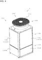
- Fig. 3 is a diagram of a front face and left side face of the outdoor unit according to Embodiment 1 of the present invention as viewed obliquely
- Fig. 4 is a diagram of a rear face and right side face of the outdoor unit shown in Fig. 3 as viewed obliquely
- Fig. 5 is a diagram schematically showing a cross section of a heat exchange chamber of the outdoor unit shown in Figs. 3 and 4
- Fig. 6 is a diagram schematically showing a cross section of that part of the outdoor unit shown in Figs. 3 and 4 in which a fan unit is housed
- Fig. 7 is a diagram describing how a mounting member shown in Fig. 6 is attached to a body casing
- Fig. 8 is an enlarged view of a fan motor and the mounting member shown in Fig. 7 .
- a specific structure of the outdoor unit 1 according to the present embodiment will be described with reference to Figs. 3 to 8 .
- the outdoor unit 1 includes a body casing 101, which houses a compressor 12, a flow path selector 14, a decompressor 16, a heat exchanger 18, an accumulator 26, and other components inside.
- the body casing 101 has, for example, a cuboid shape, in which intake portions 104 configured to suck air are formed in lateral sides and a blowout portion 109 is formed in a top to blow out air. That is, the outdoor unit 1 according to the present embodiment sucks air from the lateral sides and blows out the sucked air through the top.
- a lower part of the body casing 101 is covered with an open/close panel 102A, a left lower panel 102B, a rear lower panel 102C, and a right lower panel 102D, forming a machine chamber 103 in which, for example, the compressor 12 is housed.
- the open/close panel 102A, left lower panel 102B, rear lower panel 102C, and right lower panel 102D are substantially flat-plate members, making up an outer shell of a lower part of the outdoor unit 1.
- the open/close panel 102A is disposed in a lower part of the front face of the outdoor unit 1, the left lower panel 102B is disposed in a lower part of the left side face of the outdoor unit 1, the rear lower panel 102C is disposed in a lower part of the rear face of the outdoor unit 1, and the right lower panel 102D is disposed in a lower part of the right side face of the outdoor unit 1.
- the open/close panel 102A shown in Fig. 3 is attached openably/closably to the body casing 101. By opening the open/close panel 102A, it is possible to perform maintenance and the like of the compressor 12, electrical component box (not illustrated), and the like disposed inside the body casing 101. Note that in the outdoor unit 1 in the example of the present embodiment, all or part of the open/close panel 102A, left lower panel 102B, rear lower panel 102C, and right lower panel 102D may be omitted.
- a heat exchange chamber 105 housing the heat exchanger 18 is formed on top of the machine chamber 103 of the body casing 101.
- the intake portions 104 configured to suck air are provided all around the body casing 101. That is, the body casing 101 includes a front intake portion 104A configured to suck air through a front face, a left intake portion 104B configured to suck air through a left side face, a rear intake portion 104C configured to suck air through a rear face, and a right intake portion 104D configured to suck air through a right face.
- a panel in which plural air inlets configured to pass air is formed on each of the front intake portion 104A, left intake portion 104B, rear intake portion 104C, and right intake portion 104D.
- the outdoor unit 1 may be a frame-type outdoor unit in which panels are omitted.
- an upper part of the heat exchange chamber 105 of the body casing 101 forms a bell-mouth unit 106.
- the bell-mouth unit 106 has a cylindrical shape, with the blowout portion 109 formed in a top to blow out air.
- a fan 22 is housed inside the bell-mouth unit 106.
- a fan guard portion 110 configured to cover a top of the fan 22 is mounted on the bell-mouth unit 106.
- An outer periphery of the fan guard portion 110 is fixed to the bell-mouth unit 106.
- the heat exchanger 18 of the example of the present embodiment includes four heat exchange units configured to exchange heat with the air sucked through the intake portions 104 formed in four side faces. That is, the air taken in through the front intake portion 104A is heat-exchanged by passing through that part of a first heat exchanger 18A that faces the front intake portion 104A. The air taken in through the left intake portion 104B is heat-exchanged by passing through that part of a second heat exchanger 18B that faces the left intake portion 104B. The air taken in through the rear intake portion 104C is heat-exchanged by passing through that part of the second heat exchanger 18B that faces the rear intake portion 104C.
- the air taken in through the right intake portion 104D is heat-exchanged by passing through that part of the first heat exchanger 18A that faces the right intake portion 104D. Then, the air heat-exchanged by passing through the heat exchanger 18 is blown out through the blowout portion 109 shown in Figs. 3 and 4 .
- aerodynamic performance has been improved since air is sucked uniformly from all around the outdoor unit 1 including the front face, both side faces, and rear face of the outdoor unit 1.
- the outdoor unit 1 in the example of the present embodiment since the aerodynamic performance has been improved, electric power used to drive the fan is reduced, and noise produced when the fan is driven is reduced as well.
- the fan unit 24 includes the fan 22 and a fan motor 23.
- the fan unit 24 is mounted on the body casing 101 using a mounting member 90.
- the mounting member 90 includes fixture portions 92 fixed to the body casing 101 and a fan-unit holding portion 94 holding the fan motor 23 of the fan unit 24.
- the fixture portions 92 are formed on opposite sides of the fan-unit holding portion 94 and fixed to the body casing 101. That is, the fixture portions 92 are fixed to a front-side frame 86 in upper front part of the body casing 101 and to a rear-side frame 87 in upper rear part of the body casing 101.
- the fixture portions 92 may be fixed to a frame on a left side face of the body casing 101 and a frame on a right side face of the body casing 101.
- the fixture portions 92 and fan-unit holding portion 94 are connected together by connecting portions 93 and the fan-unit holding portion 94 retreats downward from the fixture portions 92.
- the mounting member 90 is shaped such that the fan-unit holding portion 94 projects downward from the fixture portions 92.
- the mounting member 90 is formed by bending or another process, and the fixture portions 92, the connecting portions 93, and the fan-unit holding portion 94 are formed integrally.
- the fan motor 23 is fixed to the fan-unit holding portion 94 retreating downward from the fixture portions 92.
- the fan motor 23 includes a drive shaft 23A protruding upward. As shown in Fig. 6 , the fan 22 is mounted on the drive shaft 23A of the fan motor 23.
- the fan 22 includes a boss 22A in a center and blades 22B formed around the boss 22A. An upper part of the boss 22A retreats below tops of the blades 22B, reducing the risk of contact between the fan guard portion 110 and the fan 22. This is because an outer periphery of the fan guard portion 110 is fixed to the bell-mouth unit 106. Therefore, as indicated by an imaginary line 110A, when a force is applied to the fan guard portion 110, a central portion of the fan guard portion 110 is most prone to flexure. In the example of the present embodiment, since the boss 22A in the center of the fan 22 retreats downward from the blades 22B, the risk of contact between the fan guard portion 110 and the fan 22 is curbed.
- Fig. 9 is a diagram describing a relationship between radial position of the fan and intake rate of the fan.
- a suction rate decreases on that side of the blades 22B that is closer to the boss 22A and increases on that side of the blades 22B that is farther from the boss 22A. Therefore, on an outer side of the blades 22B, by providing a large distance between the blades 22B and the mounting member 90, it is possible to reduce intake loss of the fan 22.
- Fig. 9 is a diagram describing a relationship between radial position of the fan and intake rate of the fan.
- a connection position between the fixture portion 92 and the connecting portion 93 is located outward of an intermediate position of a straight line joining a connecting portion between the boss 22A and each blade 22B to an end portion of the blade 22B. That is, the mounting member 90 is shaped to start bending down from the fixture portion 92 at a position outward of an intermediate position of the blade 22B.
- the connecting portion 93 is shaped to bend down vertically from the fixture portion 92, but may be shaped to bend down obliquely from the fixture portion 92.
- a distance between a lower part of the blade 22B and the mounting member 90 is equal to a length between the lower part of the blade 22B and the fan-unit holding portion 94, making it possible to reduce intake loss of the fan 22.
- the intake loss of the fan 22 can be reduced by placing the connecting position between the fixture portion 92 and the connecting portion 93 outward of the intermediate position of the straight line joining the connecting portion between the boss 22A and each blade 22B to the end portion of the blade 22B, more preferably the intake loss of the fan 22 can be reduced by placing the connecting position between the fixture portion 92 and the connecting portion 93 outward of the end portion of the blade 22B.
- Fig. 10 is a diagram of Comparative Example 1, which is a comparative example to Fig. 5
- Fig. 11 is a diagram of Comparative Example 2, which is a comparative example to Fig. 6
- Fig. 12 is a diagram comparing the outdoor unit of Embodiment 1, Comparative Example 1, and Comparative Example 2 with one another in terms of intake/exhaust losses of the outdoor unit.
- A represents intake loss of the fan itself
- B represents intake loss of the fan caused by a mounting member
- C represents intake loss caused by placement of a heat exchanger
- D represents exhaust loss caused during exhaust.
- a heat exchanger 180 placed in a heat exchange chamber 150 has a double-bend shape.
- Comparative Example 1 is configured such that the air sucked through three side faces--namely, a side face 140A, a side face 140B, and a side face 140C--will pass through the heat exchanger 180.
- air is not sucked uniformly in a circumferential direction of the heat exchange chamber 150, resulting in poor intake balance and thereby increasing the intake loss C due to the placement of the heat exchanger as shown in Fig. 12 .
- a fan unit 240 including a fan 220 and a fan motor 230 is mounted on a body casing via a linear mounting member 190.
- a boss 220A in a central portion of the fan 220 is located above blades 220B and closest to a fan guard portion 111.
- the fan guard portion 111 is most prone to flexure in a central portion as indicated by an imaginary line 111A. Therefore, in Comparative Example 2, there is increased risk of contact between the fan guard portion 111 and the boss 220A.
- the boss 22A retreats downward from the blades 22B as shown in Fig. 6 , the risk of contact between the fan guard portion 110 and the fan 22 is reduced.
- the outdoor unit 1 according to the present embodiment does not need to make the lower parts of the blades 22B protrude greatly downward to obtain aerodynamic characteristics. Therefore, the outdoor unit 1 according to the present embodiment allows a greater distance between the lower parts of the blades 22B and the mounting member 90, reducing the intake loss B of the fan caused by the mounting member as shown in Fig. 12 .
- the fan unit 24 is mounted on the body casing 101 via the mounting member 90.
- the mounting member 90 includes the fixture portion 92 fixed to the body casing and the fan-unit holding portion 94 holding the fan unit 24, where the fan-unit holding portion 94 retreats from the fixture portion 92.
- the outdoor unit 1 is downsized in a height direction. Also, since the fan unit 24 is held in the fan-unit holding portion 94 retreating downward from the fixture portion 92, a center of gravity of the outdoor unit 1 can be lowered.
- the boss 22A in the center of the fan 22 retreats downward from the tops of the blades 22B. Since the outer periphery of the fan guard portion 110 covering the top of the fan 22 is fixed to the bell-mouth unit 106 of the body casing 101, the fan guard portion 110 is prone to flexure in the central portion. In the outdoor unit 1 according to the present embodiment, since the boss 22A in the center of the fan 22 retreats, the risk of contact between the fan 22 and the fan guard portion 110 is curbed, improving safety.
- the boss 22A of the fan 22 retreats downward from the tops of the blades 22B, and the blades 22B partially protrude above the boss 22A. Therefore, in the present embodiment, the lower parts of the blades 22B can be placed at a higher level, allowing a greater distance between the lower parts of the blade 22B and the mounting member 90. Thus, the present embodiment reduces the intake loss of the fan 22 caused by the mounting member 90 and thereby reduces noise as well.
- the present invention is not limited to the above embodiment, and various changes can be made without departing from the scope of the present invention. That is, the configurations of the above embodiment may be improved as appropriate and at least part of the configurations may be substituted with another configuration. Furthermore, components whose arrangement is not limited specifically are not limited to the arrangement disclosed in the embodiment and may be placed at positions where the functions of the components can be achieved.
Landscapes
- Engineering & Computer Science (AREA)
- Chemical & Material Sciences (AREA)
- Combustion & Propulsion (AREA)
- Mechanical Engineering (AREA)
- General Engineering & Computer Science (AREA)
- Other Air-Conditioning Systems (AREA)
Abstract
Description
- The present invention relates to an outdoor unit configured to suck air from a lateral side and blow out the sucked air upward.
- Conventionally, outdoor units that suck air from a lateral side and blow out the sucked air upward are known (see, for example, Patent Literature 1).
- Patent Literature 1: Japanese Patent No.
5398283 - However, with conventional outdoor units such as that described in
Patent Literature 1, a fan unit is mounted on a linear mounting member attached to a body casing, upsizing the outdoor unit. - The present invention has been made in view of the above problem and has an object to provide a downsized outdoor unit.
- An outdoor unit according to one embodiment of the present invention comprises: a body casing including an intake portion that is formed in a lateral side of the body casing and through which air is sucked, a blowout portion formed in a top of the body casing, the blowout portion being configured to blow out the air sucked through the intake portion, and an air path formed between the intake portion and the blowout portion; a heat exchanger disposed in the air path; a fan unit disposed in the air path above the heat exchanger; and a mounting member mounting the fan unit on the body casing, wherein the mounting member includes a fixture portion fixed to the body casing and a fan-unit holding portion holding the fan unit, and the fan-unit holding portion retreats downward from the fixture portion.
- Since the fan unit is held in the fan-unit holding portion retreating downward from the fixture portion the present invention provides a downsized outdoor unit.
-
- Fig. 1
- is a diagram showing an example of a configuration of an outdoor unit according to
Embodiment 1 of the present invention. - Fig. 2
- is a diagram showing an example of a configuration of an indoor unit connected to the outdoor unit shown in
Fig. 1 . - Fig. 3
- is a diagram of a front face and left side face of the outdoor unit according to
Embodiment 1 of the present invention as viewed obliquely. - Fig. 4
- is a diagram of a rear face and right side face of the outdoor unit shown in
Fig. 3 as viewed obliquely. - Fig. 5
- is a diagram schematically showing a cross section of a heat exchange chamber of the outdoor unit shown in
Figs. 3 and4 . - Fig. 6
- is a diagram schematically showing a cross section of that part of the outdoor unit shown in
Figs. 3 and4 in which a fan unit is housed. - Fig. 7
- is a diagram describing how a mounting member shown in
Fig. 6 is attached to a body casing. - Fig. 8
- is an enlarged view of a fan motor and the mounting member shown in
Fig. 7 . - Fig. 9
- is a diagram describing a relationship between radial position of a fan and intake rate of the fan.
- Fig. 10
- is a diagram of Comparative Example 1, which is a comparative example to
Fig. 5 . - Fig. 11
- is a diagram of Comparative Example 2, which is a comparative example to
Fig. 6 . - Fig. 12
- is a diagram comparing the outdoor unit of
Embodiment 1, Comparative Example 1, and Comparative Example 2 with one another in terms of intake/exhaust losses of the outdoor unit. - Embodiments of the present invention will be described below with reference to the drawings. Note that in each drawing, the same or equivalent components are denoted by the same reference numerals, and description thereof will be omitted or simplified as appropriate. Also, shapes, sizes, arrangement, and the like of the components described in each drawing can be changed as appropriate within the scope of the present invention.
-
Fig. 1 is a diagram showing an example of a configuration of an outdoor unit according toEmbodiment 1 of the present invention andFig. 2 is a diagram showing an example of a configuration of an indoor unit connected to the outdoor unit shown inFig. 1 . Theoutdoor unit 1 shown inFig. 1 and theindoor unit 200 shown inFig. 2 are connected with each other via refrigerant pipes, thereby making up a non-illustrated refrigeration cycle apparatus. The non-illustrated refrigeration cycle apparatus is applied, for example, to air-conditioning devices configured to air-condition buildings, commercial facilities, or the like. As theoutdoor unit 1 andindoor unit 200 are interconnected via the refrigerant pipes at least a compressor 12, aflow path selector 14, a useside heat exchanger 202, anexpansion device 204, and aheat exchanger 18 are interconnected via the refrigerant pipes, forming a refrigerant circuit in which refrigerant circulates. - The
indoor unit 200 shown inFig. 2 is installed in a room or the like to be air-conditioned and equipped, for example, with the useside heat exchanger 202 andexpansion device 204. The useside heat exchanger 202 is designed to exchange heat, for example, between refrigerant and air, and is configured to include, for example, a heat transfer tube through which the refrigerant flows, and plural fins attached to the heat transfer tube. An indoor fan (not illustrated) configured to send air to the useside heat exchanger 202 is installed in a neighborhood of the useside heat exchanger 202. Theexpansion device 204 is designed to expand refrigerant and is, for example, an LEV (linear electronic expansion valve) whose opening degree can be adjusted, but may be a capillary tube or the like whose opening degree cannot be adjusted. - The
outdoor unit 1 shown inFig. 1 is installed outdoors outside the room and functions as a heat source apparatus configured to discharge or supply heat produced by air-conditioning. Theoutdoor unit 1 includes a compressor 12, a firstflow path selector 14A, a second flow path selector 14B, afirst decompressor 16A, a second decompressor 16B, afirst heat exchanger 18A, a second heat exchanger 18B, and anaccumulator 26. Note that in the following description, for ease of understanding of the present embodiment, the firstflow path selector 14A and second flow path selector 14B may be referred to simply as aflow path selector 14, thefirst decompressor 16A and second decompressor 16B may be referred to simply as adecompressor 16, and thefirst heat exchanger 18A and second heat exchanger 18B may be referred to simply as aheat exchanger 18. - The compressor 12 is designed to suck and compress refrigerant, and then discharge the refrigerant in a high-temperature, high-pressure state. The compressor 12 is, for example, a capacity-controllable inverter compressor, but may be a constant velocity type. The
flow path selector 14 is designed to switch between heating flow path and cooling flow path according to operation mode, which is switched between cooling operation and heating operation, and is made up, for example, of a four-way valve. Theflow path selector 14 may be configured by combining plural two-way valves or the like. - The
decompressor 16 is designed to decompress the refrigerant caused to flow into theheat exchanger 18 and is, for example, a motor-operated valve whose opening degree can be adjusted, but may be a capillary tube or the like whose opening degree cannot be adjusted. Theheat exchanger 18 is designed to exchange heat between refrigerant and air, and is configured to include, for example, a heat transfer tube through which the refrigerant flows, and plural fins attached to the heat transfer tube. The heat transfer tube has, for example, a circular or flat shape. The fins are disposed in a direction parallel to a direction in which air flows. Theaccumulator 26 is designed to accumulate the refrigerant and is connected to a suction side of the compressor 12. Of the refrigerant accumulated in theaccumulator 26, the compressor 12 sucks gas refrigerant. - Next, an operation example of the
outdoor unit 1 and theindoor unit 200 will be described. - First, an operation example of the
outdoor unit 1 and theindoor unit 200 during cooling operation will be described. When cooling operation is performed, each of the firstflow path selector 14A and second flow path selector 14B shown inFig. 1 is interconnecting flow paths as indicated by dashed lines. That is, the firstflow path selector 14A and second flow path selector 14B are connecting a discharge side of the compressor 12 to thefirst heat exchanger 18A and second heat exchanger 18B while connecting the suction side of the compressor 12 to the useside heat exchanger 202 of theindoor unit 200 shown inFig. 2 via theaccumulator 26. The refrigerant compressed by the compressor 12 shown inFig. 1 flows through thefirst heat exchanger 18A and second heat exchanger 18B via the firstflow path selector 14A and second flow path selector 14B. The refrigerant condensed by flowing through thefirst heat exchanger 18A and second heat exchanger 18B flows out of theoutdoor unit 1 and flows into theindoor unit 200 shown inFig. 2 . The refrigerant flowing into theindoor unit 200 is expanded in theexpansion device 204 and flows through the useside heat exchanger 202. The refrigerant evaporated while flowing through the useside heat exchanger 202 flows out of theindoor unit 200 and flows into theoutdoor unit 1 shown inFig. 1 . The refrigerant flowing into theoutdoor unit 1 is accumulated in theaccumulator 26 via the firstflow path selector 14A. The refrigerant accumulated in theaccumulator 26 is sucked into the compressor 12 and compressed again. - Next, an operation example of the
outdoor unit 1 and theindoor unit 200 during heating operation will be described. When heating operation is performed, each of the firstflow path selector 14A and second flow path selector 14B shown inFig. 1 is interconnecting flow paths as indicated by solid lines. That is, the firstflow path selector 14A and second flow path selector 14B are connecting the discharge side of the compressor 12 to the useside heat exchanger 202 of theindoor unit 200 shown inFig. 2 while connecting the suction side of the compressor 12 shown inFig. 1 to thefirst heat exchanger 18A and second heat exchanger 18B via theaccumulator 26. The refrigerant compressed by the compressor 12 flows out of theoutdoor unit 1 via the firstflow path selector 14A and flows into theindoor unit 200 shown inFig. 2 . The refrigerant flowing into theindoor unit 200 flows to the useside heat exchanger 202, condensed, and expanded in theexpansion device 204. The refrigerant expanded in theexpansion device 204 flows out of theindoor unit 200 and flows into theoutdoor unit 1 shown inFig. 1 . The refrigerant flowing into theoutdoor unit 1 is decompressed in thefirst decompressor 16A and second decompressor 16B and flows through thefirst heat exchanger 18A and second heat exchanger 18B. The refrigerant evaporated while flowing through thefirst heat exchanger 18A and second heat exchanger 18B is accumulated in theaccumulator 26 via the firstflow path selector 14A and second flow path selector 14B. The refrigerant accumulated in theaccumulator 26 is sucked into the compressor 12 and compressed again. -
Fig. 3 is a diagram of a front face and left side face of the outdoor unit according toEmbodiment 1 of the present invention as viewed obliquely,Fig. 4 is a diagram of a rear face and right side face of the outdoor unit shown inFig. 3 as viewed obliquely,Fig. 5 is a diagram schematically showing a cross section of a heat exchange chamber of the outdoor unit shown inFigs. 3 and4 ,Fig. 6 is a diagram schematically showing a cross section of that part of the outdoor unit shown inFigs. 3 and4 in which a fan unit is housed,Fig. 7 is a diagram describing how a mounting member shown inFig. 6 is attached to a body casing, andFig. 8 is an enlarged view of a fan motor and the mounting member shown inFig. 7 . A specific structure of theoutdoor unit 1 according to the present embodiment will be described with reference toFigs. 3 to 8 . - As shown in
Figs. 3 and4 , theoutdoor unit 1 according to the present embodiment includes abody casing 101, which houses a compressor 12, aflow path selector 14, adecompressor 16, aheat exchanger 18, anaccumulator 26, and other components inside. Thebody casing 101 has, for example, a cuboid shape, in whichintake portions 104 configured to suck air are formed in lateral sides and ablowout portion 109 is formed in a top to blow out air. That is, theoutdoor unit 1 according to the present embodiment sucks air from the lateral sides and blows out the sucked air through the top. - A lower part of the
body casing 101 is covered with an open/close panel 102A, a left lower panel 102B, a rear lower panel 102C, and a right lower panel 102D, forming amachine chamber 103 in which, for example, the compressor 12 is housed. The open/close panel 102A, left lower panel 102B, rear lower panel 102C, and right lower panel 102D are substantially flat-plate members, making up an outer shell of a lower part of theoutdoor unit 1. The open/close panel 102A is disposed in a lower part of the front face of theoutdoor unit 1, the left lower panel 102B is disposed in a lower part of the left side face of theoutdoor unit 1, the rear lower panel 102C is disposed in a lower part of the rear face of theoutdoor unit 1, and the right lower panel 102D is disposed in a lower part of the right side face of theoutdoor unit 1. The open/close panel 102A shown inFig. 3 is attached openably/closably to thebody casing 101. By opening the open/close panel 102A, it is possible to perform maintenance and the like of the compressor 12, electrical component box (not illustrated), and the like disposed inside thebody casing 101. Note that in theoutdoor unit 1 in the example of the present embodiment, all or part of the open/close panel 102A, left lower panel 102B, rear lower panel 102C, and right lower panel 102D may be omitted. - As shown in
Figs. 3 to 5 , aheat exchange chamber 105 housing theheat exchanger 18 is formed on top of themachine chamber 103 of thebody casing 101. In the example of the present embodiment, theintake portions 104 configured to suck air are provided all around thebody casing 101. That is, thebody casing 101 includes afront intake portion 104A configured to suck air through a front face, a left intake portion 104B configured to suck air through a left side face, arear intake portion 104C configured to suck air through a rear face, and a right intake portion 104D configured to suck air through a right face. For example, a panel in which plural air inlets configured to pass air is formed on each of thefront intake portion 104A, left intake portion 104B,rear intake portion 104C, and right intake portion 104D. Note that theoutdoor unit 1 according to the present embodiment may be a frame-type outdoor unit in which panels are omitted. - As shown in
Figs. 3 and4 , an upper part of theheat exchange chamber 105 of the body casing 101 forms a bell-mouth unit 106. The bell-mouth unit 106 has a cylindrical shape, with theblowout portion 109 formed in a top to blow out air. As shown inFig. 6 , afan 22 is housed inside the bell-mouth unit 106. Afan guard portion 110 configured to cover a top of thefan 22 is mounted on the bell-mouth unit 106. An outer periphery of thefan guard portion 110 is fixed to the bell-mouth unit 106. - As the
fan 22 operates, air is sucked through thefront intake portion 104A, left intake portion 104B,rear intake portion 104C, and right intake portion 104D shown inFigs. 3 to 5 . The sucked air is heat-exchanged by passing through theheat exchanger 18, and is then discharged through theblowout portion 109 shown inFigs. 3 and4 . - As shown in
Fig. 5 , theheat exchanger 18 of the example of the present embodiment includes four heat exchange units configured to exchange heat with the air sucked through theintake portions 104 formed in four side faces. That is, the air taken in through thefront intake portion 104A is heat-exchanged by passing through that part of afirst heat exchanger 18A that faces thefront intake portion 104A. The air taken in through the left intake portion 104B is heat-exchanged by passing through that part of a second heat exchanger 18B that faces the left intake portion 104B. The air taken in through therear intake portion 104C is heat-exchanged by passing through that part of the second heat exchanger 18B that faces therear intake portion 104C. The air taken in through the right intake portion 104D is heat-exchanged by passing through that part of thefirst heat exchanger 18A that faces the right intake portion 104D. Then, the air heat-exchanged by passing through theheat exchanger 18 is blown out through theblowout portion 109 shown inFigs. 3 and4 . In the example of the present embodiment, aerodynamic performance has been improved since air is sucked uniformly from all around theoutdoor unit 1 including the front face, both side faces, and rear face of theoutdoor unit 1. With theoutdoor unit 1 in the example of the present embodiment, since the aerodynamic performance has been improved, electric power used to drive the fan is reduced, and noise produced when the fan is driven is reduced as well. - As shown in
Fig. 6 , thefan unit 24 includes thefan 22 and afan motor 23. Thefan unit 24 is mounted on thebody casing 101 using a mountingmember 90. As shown inFigs. 6 and7 , the mountingmember 90 includesfixture portions 92 fixed to thebody casing 101 and a fan-unit holding portion 94 holding thefan motor 23 of thefan unit 24. Thefixture portions 92 are formed on opposite sides of the fan-unit holding portion 94 and fixed to thebody casing 101. That is, thefixture portions 92 are fixed to a front-side frame 86 in upper front part of thebody casing 101 and to a rear-side frame 87 in upper rear part of thebody casing 101. Note that thefixture portions 92 may be fixed to a frame on a left side face of thebody casing 101 and a frame on a right side face of thebody casing 101. As shown inFigs. 7 and 8 , thefixture portions 92 and fan-unit holding portion 94 are connected together by connecting portions 93 and the fan-unit holding portion 94 retreats downward from thefixture portions 92. That is, the mountingmember 90 is shaped such that the fan-unit holding portion 94 projects downward from thefixture portions 92. For example, the mountingmember 90 is formed by bending or another process, and thefixture portions 92, the connecting portions 93, and the fan-unit holding portion 94 are formed integrally. Thefan motor 23 is fixed to the fan-unit holding portion 94 retreating downward from thefixture portions 92. - The
fan motor 23 includes a drive shaft 23A protruding upward. As shown inFig. 6 , thefan 22 is mounted on the drive shaft 23A of thefan motor 23. Thefan 22 includes a boss 22A in a center and blades 22B formed around the boss 22A. An upper part of the boss 22A retreats below tops of the blades 22B, reducing the risk of contact between thefan guard portion 110 and thefan 22. This is because an outer periphery of thefan guard portion 110 is fixed to the bell-mouth unit 106. Therefore, as indicated by an imaginary line 110A, when a force is applied to thefan guard portion 110, a central portion of thefan guard portion 110 is most prone to flexure. In the example of the present embodiment, since the boss 22A in the center of thefan 22 retreats downward from the blades 22B, the risk of contact between thefan guard portion 110 and thefan 22 is curbed. -
Fig. 9 is a diagram describing a relationship between radial position of the fan and intake rate of the fan. As shown inFig. 9 , on a suction side of thefan 22, a suction rate decreases on that side of the blades 22B that is closer to the boss 22A and increases on that side of the blades 22B that is farther from the boss 22A. Therefore, on an outer side of the blades 22B, by providing a large distance between the blades 22B and the mountingmember 90, it is possible to reduce intake loss of thefan 22. As shown inFig. 6 , in the example of the present embodiment, a connection position between thefixture portion 92 and the connecting portion 93 is located outward of an intermediate position of a straight line joining a connecting portion between the boss 22A and each blade 22B to an end portion of the blade 22B. That is, the mountingmember 90 is shaped to start bending down from thefixture portion 92 at a position outward of an intermediate position of the blade 22B. For example, the connecting portion 93 is shaped to bend down vertically from thefixture portion 92, but may be shaped to bend down obliquely from thefixture portion 92. In the example of the present embodiment, on an outer side of the blade 22B, a distance between a lower part of the blade 22B and the mountingmember 90 is equal to a length between the lower part of the blade 22B and the fan-unit holding portion 94, making it possible to reduce intake loss of thefan 22. Note that whereas the intake loss of thefan 22 can be reduced by placing the connecting position between thefixture portion 92 and the connecting portion 93 outward of the intermediate position of the straight line joining the connecting portion between the boss 22A and each blade 22B to the end portion of the blade 22B, more preferably the intake loss of thefan 22 can be reduced by placing the connecting position between thefixture portion 92 and the connecting portion 93 outward of the end portion of the blade 22B. -
Fig. 10 is a diagram of Comparative Example 1, which is a comparative example toFig. 5 ,Fig. 11 is a diagram of Comparative Example 2, which is a comparative example toFig. 6 , andFig. 12 is a diagram comparing the outdoor unit ofEmbodiment 1, Comparative Example 1, and Comparative Example 2 with one another in terms of intake/exhaust losses of the outdoor unit. Note that inFig. 12 , A represents intake loss of the fan itself, B represents intake loss of the fan caused by a mounting member, C represents intake loss caused by placement of a heat exchanger, and D represents exhaust loss caused during exhaust. - As shown in
Fig. 10 , in Comparative Example 1, aheat exchanger 180 placed in aheat exchange chamber 150 has a double-bend shape. Comparative Example 1 is configured such that the air sucked through three side faces--namely, a side face 140A, a side face 140B, and a side face 140C--will pass through theheat exchanger 180. In Comparative Example 1, air is not sucked uniformly in a circumferential direction of theheat exchange chamber 150, resulting in poor intake balance and thereby increasing the intake loss C due to the placement of the heat exchanger as shown inFig. 12 . Compared to Comparative Example 1, since theoutdoor unit 1 according to the present embodiment is configured such that air will be sucked uniformly from all around theoutdoor unit 1 including the front face, both side faces, and rear face as shown inFig. 5 , the intake loss C due to the placement of the heat exchanger is improved. - As shown in
Fig. 11 , in Comparative Example 2, afan unit 240 including afan 220 and afan motor 230 is mounted on a body casing via a linear mountingmember 190. In Comparative Example 2, a boss 220A in a central portion of thefan 220 is located aboveblades 220B and closest to a fan guard portion 111. The fan guard portion 111 is most prone to flexure in a central portion as indicated by an imaginary line 111A. Therefore, in Comparative Example 2, there is increased risk of contact between the fan guard portion 111 and the boss 220A. Compared to Comparative Example 2, in theoutdoor unit 1 according to the present embodiment, since the boss 22A retreats downward from the blades 22B as shown inFig. 6 , the risk of contact between thefan guard portion 110 and thefan 22 is reduced. - Also, as shown in
Fig. 11 , in Comparative Example 2, since the boss 220A of thefan 220 is located above theblades 220B, to obtain aerodynamic characteristics, lower parts of theblades 220B protrude greatly downward, coming close to the mountingmember 190. In Comparative Example 2, since the lower parts of theblades 220B and the mountingmember 190 are located close to each other, preventing air intake of thefan 220, the intake loss B of the fan caused by the mounting member is increased as shown inFig. 12 . Compared to Comparative Example 2, in theoutdoor unit 1 according to the present embodiment, as shown inFig. 6 , the boss 22A retreats downward from an upper part of the blades 22B and the blades 22B partially protrude above the boss 22A. Unlike Comparative Example 2, theoutdoor unit 1 according to the present embodiment does not need to make the lower parts of the blades 22B protrude greatly downward to obtain aerodynamic characteristics. Therefore, theoutdoor unit 1 according to the present embodiment allows a greater distance between the lower parts of the blades 22B and the mountingmember 90, reducing the intake loss B of the fan caused by the mounting member as shown inFig. 12 . - Note that an outdoor unit in which air is not sucked uniformly from all around the
heat exchange chamber 150 as with Comparative Example 1 shown inFig. 10 incurs great intake loss C due to the placement of the heat exchanger and the intake loss B of the fan caused by the mounting member is diminished in a relative sense, as shown inFig. 12 . Therefore, with an outdoor unit such as Comparative Example 1, an effect obtained by improving the intake loss B of the fan caused by the mounting member is insignificant. However, with the outdoor unit in which air is sucked uniformly from all around the outdoor unit including the front face, both side faces, and rear face as shown inFig. 5 , since the intake loss B of the fan caused by the mounting member has an increased impact as shown inFig. 12 , an effect of reducing the intake loss B of the fan caused by the mounting member is remarkable. - As described above, in the
outdoor unit 1 according to the present embodiment, thefan unit 24 is mounted on thebody casing 101 via the mountingmember 90. The mountingmember 90 includes thefixture portion 92 fixed to the body casing and the fan-unit holding portion 94 holding thefan unit 24, where the fan-unit holding portion 94 retreats from thefixture portion 92. In the present embodiment, since thefan unit 24 is held in the fan-unit holding portion 94 depressed downward from thefixture portion 92, theoutdoor unit 1 is downsized in a height direction. Also, since thefan unit 24 is held in the fan-unit holding portion 94 retreating downward from thefixture portion 92, a center of gravity of theoutdoor unit 1 can be lowered. - Also, in the
outdoor unit 1 according to the present embodiment, the boss 22A in the center of thefan 22 retreats downward from the tops of the blades 22B. Since the outer periphery of thefan guard portion 110 covering the top of thefan 22 is fixed to the bell-mouth unit 106 of thebody casing 101, thefan guard portion 110 is prone to flexure in the central portion. In theoutdoor unit 1 according to the present embodiment, since the boss 22A in the center of thefan 22 retreats, the risk of contact between thefan 22 and thefan guard portion 110 is curbed, improving safety. - Also, in the
outdoor unit 1 according to the present embodiment, the boss 22A of thefan 22 retreats downward from the tops of the blades 22B, and the blades 22B partially protrude above the boss 22A. Therefore, in the present embodiment, the lower parts of the blades 22B can be placed at a higher level, allowing a greater distance between the lower parts of the blade 22B and the mountingmember 90. Thus, the present embodiment reduces the intake loss of thefan 22 caused by the mountingmember 90 and thereby reduces noise as well. - The present invention is not limited to the above embodiment, and various changes can be made without departing from the scope of the present invention. That is, the configurations of the above embodiment may be improved as appropriate and at least part of the configurations may be substituted with another configuration. Furthermore, components whose arrangement is not limited specifically are not limited to the arrangement disclosed in the embodiment and may be placed at positions where the functions of the components can be achieved.
-
- 1
- outdoor unit
- 12
- compressor
- 14
- flow path selector
- 14A
- first flow path selector
- 14B
- second flow path selector
- 16
- decompressor
- 16A
- first decompressor
- 16B
- second decompressor
- 18
- heat exchanger
- 18A
- first heat exchanger
- 18B
- second heat exchanger
- 22
- fan
- 22A
- boss
- 22B
- blade
- 23
- fan motor
- 24
- fan unit
- 26
- accumulator
- 86
- front-side frame
- 87
- rear-side frame
- 90
- mounting member
- 92
- fixture portion
- 93
- connecting portion
- 94
- fan-unit holding portion
- 101
- body casing
- 102A
- open/close panel
- 102B
- left lower panel
- 102C
- rear lower panel
- 102D
- right lower panel
- 103
- machine chamber
- 104
- intake portion
- 104A
- front intake portion
- 104B
- left intake portion
- 104C
- rear intake portion
- 104D
- right intake portion
- 105
- heat exchange chamber
- 106
- bell-mouth unit
- 109
- air outlet
- 110
- fan guard portion
- 110
- imaginary line
- 111
- fan guard portion
- 111A
- imaginary line
- 140A
- side face
- 140B
- side face
- 140C
- side face
- 150
- heat exchange chamber
- 180
- heat exchanger
- 190
- mounting member
- 200
- indoor unit
- 202
- use side heat exchanger
- 204
- expansion device
- 220
- fan
- 220A
- boss
- 220B
- blade
- 230
- fan motor
- 240
- fan unit
Claims (6)
- An outdoor unit comprising:a body casing includingan intake portion that is formed in a lateral side of the body casing and through which air is sucked,a blowout portion formed in a top of the body casing, the blowout portion being configured to blow out the air sucked through the intake portion, andan air path formed between the intake portion and the blowout portion;a heat exchanger disposed in the air path;a fan unit disposed in the air path above the heat exchanger; anda mounting member mounting the fan unit on the body casing,wherein the mounting member includes a fixture portion fixed to the body casing and a fan-unit holding portion holding the fan unit, andthe fan-unit holding portion retreats downward from the fixture portion.
- The outdoor unit of claim 1, wherein
the fan unit includes a fan motor provided with a drive shaft protruding upward and a fan mounted on the drive shaft,
the fan includes a boss in a center and blades formed around the boss, and
an upper part of the boss retreats downward from tops of the blades. - The outdoor unit of claim 2, further comprising a fan guard portion configured to cover a top of the fan, wherein
an outer periphery of the fan guard portion is fixed to the body casing. - The outdoor unit of claim 2 or 3, wherein the mounting member is shaped to be bent down from the fixture portion at a position outward of an intermediate position of a straight line joining a connecting portion between the boss and each of the blades to an end portion of the blade.
- The outdoor unit of any one of claims 1 to 4, wherein
the body casing is shaped to include four side faces on lateral sides, and
the mounting member is fixed to the body casing on both sides of the side faces facing each other. - The outdoor unit of claim 5, wherein
the intake portion is formed in each of the four side faces, and
the heat exchanger includes four heat exchange units each facing each of the intake portions and configured to exchange heat with the air sucked through each of the intake portions.
Applications Claiming Priority (1)
| Application Number | Priority Date | Filing Date | Title |
|---|---|---|---|
| PCT/JP2015/083553 WO2017094056A1 (en) | 2015-11-30 | 2015-11-30 | Outdoor unit |
Publications (3)
| Publication Number | Publication Date |
|---|---|
| EP3385627A1 true EP3385627A1 (en) | 2018-10-10 |
| EP3385627A4 EP3385627A4 (en) | 2018-12-05 |
| EP3385627B1 EP3385627B1 (en) | 2023-04-12 |
Family
ID=58796506
Family Applications (1)
| Application Number | Title | Priority Date | Filing Date |
|---|---|---|---|
| EP15909686.6A Active EP3385627B1 (en) | 2015-11-30 | 2015-11-30 | Outdoor unit |
Country Status (5)
| Country | Link |
|---|---|
| US (1) | US20180274800A1 (en) |
| EP (1) | EP3385627B1 (en) |
| JP (1) | JP6482679B2 (en) |
| CN (1) | CN108431509A (en) |
| WO (1) | WO2017094056A1 (en) |
Families Citing this family (2)
| Publication number | Priority date | Publication date | Assignee | Title |
|---|---|---|---|---|
| JP6879458B2 (en) * | 2017-03-15 | 2021-06-02 | 株式会社富士通ゼネラル | Outdoor unit of air conditioner |
| US10684054B2 (en) * | 2017-05-22 | 2020-06-16 | Trane International Inc. | Tension support system for motorized fan |
Family Cites Families (15)
| Publication number | Priority date | Publication date | Assignee | Title |
|---|---|---|---|---|
| US4307778A (en) * | 1980-04-11 | 1981-12-29 | Carrier Corporation | Heat exchange unit having an internal support |
| JPH0623862Y2 (en) * | 1988-09-06 | 1994-06-22 | ダイキン工業株式会社 | Outdoor unit fan motor base mounting structure |
| AU2548601A (en) * | 2000-01-14 | 2001-07-24 | Toshiba Carrier Corporation | Outdoor unit of air conditioner |
| JP3913441B2 (en) * | 2000-04-24 | 2007-05-09 | 三洋電機株式会社 | Air conditioner outdoor unit |
| JP2001349580A (en) * | 2000-06-05 | 2001-12-21 | Sanyo Electric Co Ltd | Outdoor machine of air conditioner |
| JP3847567B2 (en) * | 2001-02-20 | 2006-11-22 | 三菱電機株式会社 | Air conditioner outdoor unit |
| KR101075231B1 (en) * | 2003-12-19 | 2011-10-19 | 삼성전자주식회사 | air conditioner |
| KR100954358B1 (en) * | 2006-01-25 | 2010-04-27 | 엘지전자 주식회사 | Control box of air conditioner outdoor unit |
| KR20090043715A (en) * | 2007-10-30 | 2009-05-07 | 삼성전자주식회사 | Fan guard and outdoor unit of air conditioner having same |
| JP5127854B2 (en) * | 2010-03-11 | 2013-01-23 | 三菱電機株式会社 | Blower and heat pump device |
| JP2012072937A (en) * | 2010-09-28 | 2012-04-12 | Sanyo Electric Co Ltd | Air conditioner |
| JP2012242028A (en) * | 2011-05-20 | 2012-12-10 | Daikin Industries Ltd | Outdoor unit of refrigeration device |
| JP5924715B2 (en) * | 2013-01-16 | 2016-05-25 | 三菱電機株式会社 | Outdoor unit |
| JP5980180B2 (en) * | 2013-08-08 | 2016-08-31 | 三菱電機株式会社 | Axial flow fan and air conditioner having the axial flow fan |
| JP6718134B2 (en) * | 2016-02-29 | 2020-07-08 | 株式会社富士通ゼネラル | Air conditioner outdoor unit |
-
2015
- 2015-11-30 JP JP2017553486A patent/JP6482679B2/en active Active
- 2015-11-30 CN CN201580085121.3A patent/CN108431509A/en active Pending
- 2015-11-30 EP EP15909686.6A patent/EP3385627B1/en active Active
- 2015-11-30 US US15/764,111 patent/US20180274800A1/en not_active Abandoned
- 2015-11-30 WO PCT/JP2015/083553 patent/WO2017094056A1/en not_active Ceased
Also Published As
| Publication number | Publication date |
|---|---|
| JPWO2017094056A1 (en) | 2018-04-19 |
| JP6482679B2 (en) | 2019-03-13 |
| EP3385627A4 (en) | 2018-12-05 |
| EP3385627B1 (en) | 2023-04-12 |
| US20180274800A1 (en) | 2018-09-27 |
| WO2017094056A1 (en) | 2017-06-08 |
| CN108431509A (en) | 2018-08-21 |
Similar Documents
| Publication | Publication Date | Title |
|---|---|---|
| CN105008809B (en) | Indoor unit of air conditioner | |
| EP3379156B1 (en) | Air conditioner | |
| CN102141271B (en) | Outdoor unit for air conditioner | |
| EP2993423B1 (en) | Decorative panel and air-conditioner in-room unit provided with same | |
| EP3059509B1 (en) | Outdoor unit | |
| CN105987457A (en) | Outdoor unit of air conditioner | |
| EP3260785B1 (en) | Outdoor unit | |
| CN111486516A (en) | An air conditioner outdoor unit | |
| JP3714264B2 (en) | Air conditioner outdoor unit | |
| EP3392573B1 (en) | Outdoor machine for freezing cycle apparatus | |
| CN202792283U (en) | Outdoor unit of refrigeration device | |
| EP3385627B1 (en) | Outdoor unit | |
| US7191616B2 (en) | Front suction/discharge type outdoor unit for air-conditioner and outdoor unit installation system using it | |
| CN108027153B (en) | Outdoor machine | |
| WO2018193520A1 (en) | Outdoor unit, air conditioner, and method for manufacturing outdoor unit | |
| CN111412541A (en) | Multifunctional integrated air conditioner | |
| KR100441101B1 (en) | The lead mounting of an air-conditioner | |
| CN217952506U (en) | Air condensing units and air conditioner | |
| KR100573067B1 (en) | Wall-mounted outdoor unit for split type air conditioner and outdoor unit for split type air conditioner | |
| CN209013355U (en) | An air conditioner and an air conditioner | |
| CN100513917C (en) | Air conditioner | |
| CN206281233U (en) | A kind of top-exhausted air-conditioner compressor and top-exhausted air-conditioner | |
| US12566003B2 (en) | Outdoor unit of air conditioner | |
| CN219913258U (en) | window air conditioner | |
| CN209960633U (en) | Integrated air duct machine |
Legal Events
| Date | Code | Title | Description |
|---|---|---|---|
| STAA | Information on the status of an ep patent application or granted ep patent |
Free format text: STATUS: THE INTERNATIONAL PUBLICATION HAS BEEN MADE |
|
| PUAI | Public reference made under article 153(3) epc to a published international application that has entered the european phase |
Free format text: ORIGINAL CODE: 0009012 |
|
| STAA | Information on the status of an ep patent application or granted ep patent |
Free format text: STATUS: REQUEST FOR EXAMINATION WAS MADE |
|
| 17P | Request for examination filed |
Effective date: 20180425 |
|
| AK | Designated contracting states |
Kind code of ref document: A1 Designated state(s): AL AT BE BG CH CY CZ DE DK EE ES FI FR GB GR HR HU IE IS IT LI LT LU LV MC MK MT NL NO PL PT RO RS SE SI SK SM TR |
|
| AX | Request for extension of the european patent |
Extension state: BA ME |
|
| A4 | Supplementary search report drawn up and despatched |
Effective date: 20181106 |
|
| RIC1 | Information provided on ipc code assigned before grant |
Ipc: F24F 1/38 20110101AFI20181030BHEP Ipc: F24F 1/50 20110101ALI20181030BHEP |
|
| DAV | Request for validation of the european patent (deleted) | ||
| DAX | Request for extension of the european patent (deleted) | ||
| STAA | Information on the status of an ep patent application or granted ep patent |
Free format text: STATUS: EXAMINATION IS IN PROGRESS |
|
| 17Q | First examination report despatched |
Effective date: 20200728 |
|
| GRAP | Despatch of communication of intention to grant a patent |
Free format text: ORIGINAL CODE: EPIDOSNIGR1 |
|
| STAA | Information on the status of an ep patent application or granted ep patent |
Free format text: STATUS: GRANT OF PATENT IS INTENDED |
|
| INTG | Intention to grant announced |
Effective date: 20221020 |
|
| GRAS | Grant fee paid |
Free format text: ORIGINAL CODE: EPIDOSNIGR3 |
|
| GRAA | (expected) grant |
Free format text: ORIGINAL CODE: 0009210 |
|
| STAA | Information on the status of an ep patent application or granted ep patent |
Free format text: STATUS: THE PATENT HAS BEEN GRANTED |
|
| AK | Designated contracting states |
Kind code of ref document: B1 Designated state(s): AL AT BE BG CH CY CZ DE DK EE ES FI FR GB GR HR HU IE IS IT LI LT LU LV MC MK MT NL NO PL PT RO RS SE SI SK SM TR |
|
| REG | Reference to a national code |
Ref country code: GB Ref legal event code: FG4D |
|
| REG | Reference to a national code |
Ref country code: CH Ref legal event code: EP |
|
| REG | Reference to a national code |
Ref country code: DE Ref legal event code: R096 Ref document number: 602015083183 Country of ref document: DE |
|
| REG | Reference to a national code |
Ref country code: IE Ref legal event code: FG4D |
|
| REG | Reference to a national code |
Ref country code: AT Ref legal event code: REF Ref document number: 1559984 Country of ref document: AT Kind code of ref document: T Effective date: 20230515 |
|
| REG | Reference to a national code |
Ref country code: LT Ref legal event code: MG9D |
|
| P01 | Opt-out of the competence of the unified patent court (upc) registered |
Effective date: 20230711 |
|
| REG | Reference to a national code |
Ref country code: NL Ref legal event code: MP Effective date: 20230412 |
|
| REG | Reference to a national code |
Ref country code: AT Ref legal event code: MK05 Ref document number: 1559984 Country of ref document: AT Kind code of ref document: T Effective date: 20230412 |
|
| PG25 | Lapsed in a contracting state [announced via postgrant information from national office to epo] |
Ref country code: NL Free format text: LAPSE BECAUSE OF FAILURE TO SUBMIT A TRANSLATION OF THE DESCRIPTION OR TO PAY THE FEE WITHIN THE PRESCRIBED TIME-LIMIT Effective date: 20230412 |
|
| PG25 | Lapsed in a contracting state [announced via postgrant information from national office to epo] |
Ref country code: SE Free format text: LAPSE BECAUSE OF FAILURE TO SUBMIT A TRANSLATION OF THE DESCRIPTION OR TO PAY THE FEE WITHIN THE PRESCRIBED TIME-LIMIT Effective date: 20230412 Ref country code: PT Free format text: LAPSE BECAUSE OF FAILURE TO SUBMIT A TRANSLATION OF THE DESCRIPTION OR TO PAY THE FEE WITHIN THE PRESCRIBED TIME-LIMIT Effective date: 20230814 Ref country code: NO Free format text: LAPSE BECAUSE OF FAILURE TO SUBMIT A TRANSLATION OF THE DESCRIPTION OR TO PAY THE FEE WITHIN THE PRESCRIBED TIME-LIMIT Effective date: 20230712 Ref country code: ES Free format text: LAPSE BECAUSE OF FAILURE TO SUBMIT A TRANSLATION OF THE DESCRIPTION OR TO PAY THE FEE WITHIN THE PRESCRIBED TIME-LIMIT Effective date: 20230412 Ref country code: AT Free format text: LAPSE BECAUSE OF FAILURE TO SUBMIT A TRANSLATION OF THE DESCRIPTION OR TO PAY THE FEE WITHIN THE PRESCRIBED TIME-LIMIT Effective date: 20230412 |
|
| PG25 | Lapsed in a contracting state [announced via postgrant information from national office to epo] |
Ref country code: RS Free format text: LAPSE BECAUSE OF FAILURE TO SUBMIT A TRANSLATION OF THE DESCRIPTION OR TO PAY THE FEE WITHIN THE PRESCRIBED TIME-LIMIT Effective date: 20230412 Ref country code: PL Free format text: LAPSE BECAUSE OF FAILURE TO SUBMIT A TRANSLATION OF THE DESCRIPTION OR TO PAY THE FEE WITHIN THE PRESCRIBED TIME-LIMIT Effective date: 20230412 Ref country code: LV Free format text: LAPSE BECAUSE OF FAILURE TO SUBMIT A TRANSLATION OF THE DESCRIPTION OR TO PAY THE FEE WITHIN THE PRESCRIBED TIME-LIMIT Effective date: 20230412 Ref country code: LT Free format text: LAPSE BECAUSE OF FAILURE TO SUBMIT A TRANSLATION OF THE DESCRIPTION OR TO PAY THE FEE WITHIN THE PRESCRIBED TIME-LIMIT Effective date: 20230412 Ref country code: IS Free format text: LAPSE BECAUSE OF FAILURE TO SUBMIT A TRANSLATION OF THE DESCRIPTION OR TO PAY THE FEE WITHIN THE PRESCRIBED TIME-LIMIT Effective date: 20230812 Ref country code: HR Free format text: LAPSE BECAUSE OF FAILURE TO SUBMIT A TRANSLATION OF THE DESCRIPTION OR TO PAY THE FEE WITHIN THE PRESCRIBED TIME-LIMIT Effective date: 20230412 Ref country code: GR Free format text: LAPSE BECAUSE OF FAILURE TO SUBMIT A TRANSLATION OF THE DESCRIPTION OR TO PAY THE FEE WITHIN THE PRESCRIBED TIME-LIMIT Effective date: 20230713 Ref country code: AL Free format text: LAPSE BECAUSE OF FAILURE TO SUBMIT A TRANSLATION OF THE DESCRIPTION OR TO PAY THE FEE WITHIN THE PRESCRIBED TIME-LIMIT Effective date: 20230412 |
|
| PG25 | Lapsed in a contracting state [announced via postgrant information from national office to epo] |
Ref country code: FI Free format text: LAPSE BECAUSE OF FAILURE TO SUBMIT A TRANSLATION OF THE DESCRIPTION OR TO PAY THE FEE WITHIN THE PRESCRIBED TIME-LIMIT Effective date: 20230412 |
|
| REG | Reference to a national code |
Ref country code: DE Ref legal event code: R097 Ref document number: 602015083183 Country of ref document: DE |
|
| PG25 | Lapsed in a contracting state [announced via postgrant information from national office to epo] |
Ref country code: SK Free format text: LAPSE BECAUSE OF FAILURE TO SUBMIT A TRANSLATION OF THE DESCRIPTION OR TO PAY THE FEE WITHIN THE PRESCRIBED TIME-LIMIT Effective date: 20230412 |
|
| PG25 | Lapsed in a contracting state [announced via postgrant information from national office to epo] |
Ref country code: SM Free format text: LAPSE BECAUSE OF FAILURE TO SUBMIT A TRANSLATION OF THE DESCRIPTION OR TO PAY THE FEE WITHIN THE PRESCRIBED TIME-LIMIT Effective date: 20230412 Ref country code: SK Free format text: LAPSE BECAUSE OF FAILURE TO SUBMIT A TRANSLATION OF THE DESCRIPTION OR TO PAY THE FEE WITHIN THE PRESCRIBED TIME-LIMIT Effective date: 20230412 Ref country code: RO Free format text: LAPSE BECAUSE OF FAILURE TO SUBMIT A TRANSLATION OF THE DESCRIPTION OR TO PAY THE FEE WITHIN THE PRESCRIBED TIME-LIMIT Effective date: 20230412 Ref country code: EE Free format text: LAPSE BECAUSE OF FAILURE TO SUBMIT A TRANSLATION OF THE DESCRIPTION OR TO PAY THE FEE WITHIN THE PRESCRIBED TIME-LIMIT Effective date: 20230412 Ref country code: DK Free format text: LAPSE BECAUSE OF FAILURE TO SUBMIT A TRANSLATION OF THE DESCRIPTION OR TO PAY THE FEE WITHIN THE PRESCRIBED TIME-LIMIT Effective date: 20230412 Ref country code: CZ Free format text: LAPSE BECAUSE OF FAILURE TO SUBMIT A TRANSLATION OF THE DESCRIPTION OR TO PAY THE FEE WITHIN THE PRESCRIBED TIME-LIMIT Effective date: 20230412 |
|
| PLBE | No opposition filed within time limit |
Free format text: ORIGINAL CODE: 0009261 |
|
| STAA | Information on the status of an ep patent application or granted ep patent |
Free format text: STATUS: NO OPPOSITION FILED WITHIN TIME LIMIT |
|
| 26N | No opposition filed |
Effective date: 20240115 |
|
| PG25 | Lapsed in a contracting state [announced via postgrant information from national office to epo] |
Ref country code: SI Free format text: LAPSE BECAUSE OF FAILURE TO SUBMIT A TRANSLATION OF THE DESCRIPTION OR TO PAY THE FEE WITHIN THE PRESCRIBED TIME-LIMIT Effective date: 20230412 |
|
| PG25 | Lapsed in a contracting state [announced via postgrant information from national office to epo] |
Ref country code: SI Free format text: LAPSE BECAUSE OF FAILURE TO SUBMIT A TRANSLATION OF THE DESCRIPTION OR TO PAY THE FEE WITHIN THE PRESCRIBED TIME-LIMIT Effective date: 20230412 Ref country code: IT Free format text: LAPSE BECAUSE OF FAILURE TO SUBMIT A TRANSLATION OF THE DESCRIPTION OR TO PAY THE FEE WITHIN THE PRESCRIBED TIME-LIMIT Effective date: 20230412 |
|
| REG | Reference to a national code |
Ref country code: CH Ref legal event code: PL |
|
| PG25 | Lapsed in a contracting state [announced via postgrant information from national office to epo] |
Ref country code: MC Free format text: LAPSE BECAUSE OF FAILURE TO SUBMIT A TRANSLATION OF THE DESCRIPTION OR TO PAY THE FEE WITHIN THE PRESCRIBED TIME-LIMIT Effective date: 20230412 |
|
| PG25 | Lapsed in a contracting state [announced via postgrant information from national office to epo] |
Ref country code: LU Free format text: LAPSE BECAUSE OF NON-PAYMENT OF DUE FEES Effective date: 20231130 |
|
| PG25 | Lapsed in a contracting state [announced via postgrant information from national office to epo] |
Ref country code: CH Free format text: LAPSE BECAUSE OF NON-PAYMENT OF DUE FEES Effective date: 20231130 |
|
| PG25 | Lapsed in a contracting state [announced via postgrant information from national office to epo] |
Ref country code: MC Free format text: LAPSE BECAUSE OF FAILURE TO SUBMIT A TRANSLATION OF THE DESCRIPTION OR TO PAY THE FEE WITHIN THE PRESCRIBED TIME-LIMIT Effective date: 20230412 Ref country code: LU Free format text: LAPSE BECAUSE OF NON-PAYMENT OF DUE FEES Effective date: 20231130 Ref country code: CH Free format text: LAPSE BECAUSE OF NON-PAYMENT OF DUE FEES Effective date: 20231130 |
|
| REG | Reference to a national code |
Ref country code: BE Ref legal event code: MM Effective date: 20231130 |
|
| REG | Reference to a national code |
Ref country code: IE Ref legal event code: MM4A |
|
| PG25 | Lapsed in a contracting state [announced via postgrant information from national office to epo] |
Ref country code: IE Free format text: LAPSE BECAUSE OF NON-PAYMENT OF DUE FEES Effective date: 20231130 |
|
| PG25 | Lapsed in a contracting state [announced via postgrant information from national office to epo] |
Ref country code: BE Free format text: LAPSE BECAUSE OF NON-PAYMENT OF DUE FEES Effective date: 20231130 |
|
| PG25 | Lapsed in a contracting state [announced via postgrant information from national office to epo] |
Ref country code: FR Free format text: LAPSE BECAUSE OF NON-PAYMENT OF DUE FEES Effective date: 20231130 |
|
| PG25 | Lapsed in a contracting state [announced via postgrant information from national office to epo] |
Ref country code: IE Free format text: LAPSE BECAUSE OF NON-PAYMENT OF DUE FEES Effective date: 20231130 Ref country code: FR Free format text: LAPSE BECAUSE OF NON-PAYMENT OF DUE FEES Effective date: 20231130 Ref country code: BE Free format text: LAPSE BECAUSE OF NON-PAYMENT OF DUE FEES Effective date: 20231130 |
|
| PG25 | Lapsed in a contracting state [announced via postgrant information from national office to epo] |
Ref country code: BG Free format text: LAPSE BECAUSE OF FAILURE TO SUBMIT A TRANSLATION OF THE DESCRIPTION OR TO PAY THE FEE WITHIN THE PRESCRIBED TIME-LIMIT Effective date: 20230412 |
|
| PG25 | Lapsed in a contracting state [announced via postgrant information from national office to epo] |
Ref country code: BG Free format text: LAPSE BECAUSE OF FAILURE TO SUBMIT A TRANSLATION OF THE DESCRIPTION OR TO PAY THE FEE WITHIN THE PRESCRIBED TIME-LIMIT Effective date: 20230412 |
|
| REG | Reference to a national code |
Ref country code: DE Ref legal event code: R084 Ref document number: 602015083183 Country of ref document: DE |
|
| PG25 | Lapsed in a contracting state [announced via postgrant information from national office to epo] |
Ref country code: CY Free format text: LAPSE BECAUSE OF FAILURE TO SUBMIT A TRANSLATION OF THE DESCRIPTION OR TO PAY THE FEE WITHIN THE PRESCRIBED TIME-LIMIT; INVALID AB INITIO Effective date: 20151130 |
|
| PG25 | Lapsed in a contracting state [announced via postgrant information from national office to epo] |
Ref country code: HU Free format text: LAPSE BECAUSE OF FAILURE TO SUBMIT A TRANSLATION OF THE DESCRIPTION OR TO PAY THE FEE WITHIN THE PRESCRIBED TIME-LIMIT; INVALID AB INITIO Effective date: 20151130 |
|
| REG | Reference to a national code |
Ref country code: GB Ref legal event code: 746 Effective date: 20250730 |
|
| PG25 | Lapsed in a contracting state [announced via postgrant information from national office to epo] |
Ref country code: TR Free format text: LAPSE BECAUSE OF FAILURE TO SUBMIT A TRANSLATION OF THE DESCRIPTION OR TO PAY THE FEE WITHIN THE PRESCRIBED TIME-LIMIT Effective date: 20230412 |
|
| PGFP | Annual fee paid to national office [announced via postgrant information from national office to epo] |
Ref country code: DE Payment date: 20250930 Year of fee payment: 11 |
|
| PGFP | Annual fee paid to national office [announced via postgrant information from national office to epo] |
Ref country code: GB Payment date: 20251001 Year of fee payment: 11 |