EP3385576A1 - A gasket assembly - Google Patents
A gasket assembly Download PDFInfo
- Publication number
- EP3385576A1 EP3385576A1 EP18154515.3A EP18154515A EP3385576A1 EP 3385576 A1 EP3385576 A1 EP 3385576A1 EP 18154515 A EP18154515 A EP 18154515A EP 3385576 A1 EP3385576 A1 EP 3385576A1
- Authority
- EP
- European Patent Office
- Prior art keywords
- assembly
- seal
- component
- retaining element
- vehicle
- Prior art date
- Legal status (The legal status is an assumption and is not a legal conclusion. Google has not performed a legal analysis and makes no representation as to the accuracy of the status listed.)
- Granted
Links
Images


Classifications
-
- F—MECHANICAL ENGINEERING; LIGHTING; HEATING; WEAPONS; BLASTING
- F16—ENGINEERING ELEMENTS AND UNITS; GENERAL MEASURES FOR PRODUCING AND MAINTAINING EFFECTIVE FUNCTIONING OF MACHINES OR INSTALLATIONS; THERMAL INSULATION IN GENERAL
- F16B—DEVICES FOR FASTENING OR SECURING CONSTRUCTIONAL ELEMENTS OR MACHINE PARTS TOGETHER, e.g. NAILS, BOLTS, CIRCLIPS, CLAMPS, CLIPS OR WEDGES; JOINTS OR JOINTING
- F16B33/00—Features common to bolt and nut
- F16B33/004—Sealing; Insulation
-
- F—MECHANICAL ENGINEERING; LIGHTING; HEATING; WEAPONS; BLASTING
- F16—ENGINEERING ELEMENTS AND UNITS; GENERAL MEASURES FOR PRODUCING AND MAINTAINING EFFECTIVE FUNCTIONING OF MACHINES OR INSTALLATIONS; THERMAL INSULATION IN GENERAL
- F16J—PISTONS; CYLINDERS; SEALINGS
- F16J15/00—Sealings
- F16J15/02—Sealings between relatively-stationary surfaces
- F16J15/06—Sealings between relatively-stationary surfaces with solid packing compressed between sealing surfaces
- F16J15/061—Sealings between relatively-stationary surfaces with solid packing compressed between sealing surfaces with positioning means
-
- F—MECHANICAL ENGINEERING; LIGHTING; HEATING; WEAPONS; BLASTING
- F16—ENGINEERING ELEMENTS AND UNITS; GENERAL MEASURES FOR PRODUCING AND MAINTAINING EFFECTIVE FUNCTIONING OF MACHINES OR INSTALLATIONS; THERMAL INSULATION IN GENERAL
- F16J—PISTONS; CYLINDERS; SEALINGS
- F16J15/00—Sealings
- F16J15/02—Sealings between relatively-stationary surfaces
- F16J15/021—Sealings between relatively-stationary surfaces with elastic packing
- F16J15/022—Sealings between relatively-stationary surfaces with elastic packing characterised by structure or material
-
- F—MECHANICAL ENGINEERING; LIGHTING; HEATING; WEAPONS; BLASTING
- F16—ENGINEERING ELEMENTS AND UNITS; GENERAL MEASURES FOR PRODUCING AND MAINTAINING EFFECTIVE FUNCTIONING OF MACHINES OR INSTALLATIONS; THERMAL INSULATION IN GENERAL
- F16J—PISTONS; CYLINDERS; SEALINGS
- F16J15/00—Sealings
- F16J15/02—Sealings between relatively-stationary surfaces
- F16J15/021—Sealings between relatively-stationary surfaces with elastic packing
- F16J15/028—Sealings between relatively-stationary surfaces with elastic packing the packing being mechanically expanded against the sealing surface
-
- F—MECHANICAL ENGINEERING; LIGHTING; HEATING; WEAPONS; BLASTING
- F16—ENGINEERING ELEMENTS AND UNITS; GENERAL MEASURES FOR PRODUCING AND MAINTAINING EFFECTIVE FUNCTIONING OF MACHINES OR INSTALLATIONS; THERMAL INSULATION IN GENERAL
- F16J—PISTONS; CYLINDERS; SEALINGS
- F16J15/00—Sealings
- F16J15/02—Sealings between relatively-stationary surfaces
- F16J15/06—Sealings between relatively-stationary surfaces with solid packing compressed between sealing surfaces
- F16J15/062—Sealings between relatively-stationary surfaces with solid packing compressed between sealing surfaces characterised by the geometry of the seat
-
- F—MECHANICAL ENGINEERING; LIGHTING; HEATING; WEAPONS; BLASTING
- F16—ENGINEERING ELEMENTS AND UNITS; GENERAL MEASURES FOR PRODUCING AND MAINTAINING EFFECTIVE FUNCTIONING OF MACHINES OR INSTALLATIONS; THERMAL INSULATION IN GENERAL
- F16J—PISTONS; CYLINDERS; SEALINGS
- F16J15/00—Sealings
- F16J15/02—Sealings between relatively-stationary surfaces
- F16J15/06—Sealings between relatively-stationary surfaces with solid packing compressed between sealing surfaces
- F16J15/068—Sealings between relatively-stationary surfaces with solid packing compressed between sealing surfaces the packing swelling under working conditions
-
- F—MECHANICAL ENGINEERING; LIGHTING; HEATING; WEAPONS; BLASTING
- F16—ENGINEERING ELEMENTS AND UNITS; GENERAL MEASURES FOR PRODUCING AND MAINTAINING EFFECTIVE FUNCTIONING OF MACHINES OR INSTALLATIONS; THERMAL INSULATION IN GENERAL
- F16J—PISTONS; CYLINDERS; SEALINGS
- F16J15/00—Sealings
- F16J15/02—Sealings between relatively-stationary surfaces
- F16J15/06—Sealings between relatively-stationary surfaces with solid packing compressed between sealing surfaces
- F16J15/08—Sealings between relatively-stationary surfaces with solid packing compressed between sealing surfaces with exclusively metal packing
- F16J15/0818—Flat gaskets
-
- F—MECHANICAL ENGINEERING; LIGHTING; HEATING; WEAPONS; BLASTING
- F16—ENGINEERING ELEMENTS AND UNITS; GENERAL MEASURES FOR PRODUCING AND MAINTAINING EFFECTIVE FUNCTIONING OF MACHINES OR INSTALLATIONS; THERMAL INSULATION IN GENERAL
- F16J—PISTONS; CYLINDERS; SEALINGS
- F16J15/00—Sealings
- F16J15/02—Sealings between relatively-stationary surfaces
- F16J15/06—Sealings between relatively-stationary surfaces with solid packing compressed between sealing surfaces
- F16J15/10—Sealings between relatively-stationary surfaces with solid packing compressed between sealing surfaces with non-metallic packing
- F16J15/104—Sealings between relatively-stationary surfaces with solid packing compressed between sealing surfaces with non-metallic packing characterised by structure
-
- F—MECHANICAL ENGINEERING; LIGHTING; HEATING; WEAPONS; BLASTING
- F16—ENGINEERING ELEMENTS AND UNITS; GENERAL MEASURES FOR PRODUCING AND MAINTAINING EFFECTIVE FUNCTIONING OF MACHINES OR INSTALLATIONS; THERMAL INSULATION IN GENERAL
- F16B—DEVICES FOR FASTENING OR SECURING CONSTRUCTIONAL ELEMENTS OR MACHINE PARTS TOGETHER, e.g. NAILS, BOLTS, CIRCLIPS, CLAMPS, CLIPS OR WEDGES; JOINTS OR JOINTING
- F16B43/00—Washers or equivalent devices; Other devices for supporting bolt-heads or nuts
- F16B43/001—Washers or equivalent devices; Other devices for supporting bolt-heads or nuts for sealing or insulation
-
- F—MECHANICAL ENGINEERING; LIGHTING; HEATING; WEAPONS; BLASTING
- F16—ENGINEERING ELEMENTS AND UNITS; GENERAL MEASURES FOR PRODUCING AND MAINTAINING EFFECTIVE FUNCTIONING OF MACHINES OR INSTALLATIONS; THERMAL INSULATION IN GENERAL
- F16J—PISTONS; CYLINDERS; SEALINGS
- F16J15/00—Sealings
- F16J15/02—Sealings between relatively-stationary surfaces
- F16J15/021—Sealings between relatively-stationary surfaces with elastic packing
- F16J15/022—Sealings between relatively-stationary surfaces with elastic packing characterised by structure or material
- F16J15/024—Sealings between relatively-stationary surfaces with elastic packing characterised by structure or material the packing being locally weakened in order to increase elasticity
- F16J15/025—Sealings between relatively-stationary surfaces with elastic packing characterised by structure or material the packing being locally weakened in order to increase elasticity and with at least one flexible lip
Definitions
- the present disclosure relates to a gasket assembly for a vehicle and is particularly, although not exclusively, concerned with a gasket assembly configured to improve maintenance of a vehicle assembly comprising a gasket.
- Many assemblies within a motor vehicle comprise gaskets that are provided to improve sealing between components of the assembly.
- the gasket may be provided in order to reduce or prevent oil leakage between the components of the assembly.
- Providing a gasket within the assembly increases the number of components within the vehicle and may increase the number of separate components that must be stored and assembled on the vehicle production line.
- the gasket may be coupled to a component of the vehicle assembly away from the main vehicle production line.
- a subassembly comprising the vehicle component and the gasket may be transported to the vehicle production line for assembly onto the vehicle.
- the gasket may comprise a retaining feature configured to couple the gasket to the component of the vehicle assembly.
- a seal assembly such as a gasket assembly, for an assembly of a vehicle
- the seal assembly comprising: a seal, e.g. a gasket, configured to create a seal between first and second components of the vehicle assembly; and a retaining element configured to couple the seal to the first component prior to assembly of the vehicle assembly, wherein at least a portion of the retaining element is deformable, e.g. permanently deformable, and is configured to deform from a first state to a second state during installation or intended use of the seal assembly, such that after said deformation the retaining element no longer couples the seal to the first component.
- a seal e.g. a gasket
- deforming may include, melting, subliming, breaking, e.g. fracturing or shattering, decomposing, e.g. thermally decomposing, oxidising, plastically deforming and/or any other form of deformation.
- the retaining element or portion thereof may be configured to deform from the first state to the second state due to the operating environment, e.g. temperature, of the seal assembly, e.g. when the temperature reaches a threshold value, for example, the intended operating temperature of the seal assembly.
- the operating environment e.g. temperature
- a threshold value for example, the intended operating temperature of the seal assembly.
- the retaining element or portion thereof may be configured to at least partially melt under the operating conditions of the seal assembly.
- the retaining element of portion thereof may have a melting point less than or equal an intended operating temperature of the seal assembly.
- the retaining element of portion thereof may have a melting temperature lower than 250 degrees Celsius or lower than 70 degrees Celsius or lower than 60 degrees Celsius.
- the retaining element of portion thereof may be made from a polymer material or a wax material.
- the retaining element or portion thereof may be frangible and may be configured to break when the seal assembly is installed into the vehicle assembly.
- the retaining element or portion thereof may break as the seal is created by the seal, e.g. when it is clamped together by first and second components to create the seal.
- the retaining element or portion thereof may break due to an operating condition of the seal assembly, e.g. a force or vibration experience by the seal assembly during operation.
- the retaining element may be configured to be at least partially received within a bore formed in the first component.
- the retaining element may be configured to extend through the bore defined in the first component, e.g. from a first side to a second side of the first component.
- the seal may define a seal aperture configured to receive a fastener for coupling the first component to the second component.
- the retaining element may extend through the seal aperture.
- the retaining element may define a retainer aperture configured to receive a fastener, e.g. the fastener for coupling the first component to the second component.
- the retainer aperture may be aligned with the seal aperture.
- the retaining element may further comprise a grip member.
- the grip member may be configured to couple to the fastener received within the retainer aperture.
- the grip member may provide resistance against the removal of the fastener from the retainer aperture.
- the grip member may comprise one or more resilient grip elements configured to deform in order to allow the fastener to be inserted through the aperture.
- the resilient grip members may be configured to grip the fastener to couple the fastener to the grip member.
- At least a portion of the grip member may be configured to deform, e.g. permanently deform, between a first state and a second state by virtue of the operating condition of the seal assembly such that the fastener may be removed from the retainer aperture when the further grip member or portion thereof is in the second state.
- the grip member or portion thereof may be configured to deform under substantially the same conditions as the retaining element of portion thereof.
- the grip member may be configured to deform under difference conditions to the retaining member.
- the retaining element may be integral with or may be separate from the seal.
- the retaining element may comprise a first flange, a second flange and a body portion extending between the first and second flanges.
- the body portion of the retaining element may be configured to extend through a bore of the first component such that the first flange is arranged on a first side of the bore, and the second flange is arranged on a second side of the bore.
- the body portion may extend through the seal body.
- the first flange may be arranged to a first side of the seal body and the second flange may be arranged to a second side of the seal body.
- the first flange and/or the body portion may be flexible, e.g. in order to permit the first flange and body portion to be inserted into the bore of the first component.
- the first flange and/or the body portion may comprise a plurality of slits configured to allow the diameter of the first flange be reduced, e.g. in order to assemble the retaining element into the opening or through the bore of the first component.
- a seal assembly for an assembly of a vehicle, the seal assembly comprising: a seal configured to create a seal between first and second components of the vehicle assembly; and a retaining element configured to couple the seal to the first component prior to assembly of the vehicle assembly, wherein the retaining element comprises a deformable portion configured to deform from a first state to a second state by virtue of the operating environment of the seal assembly, such that the seal is no longer coupled to the first component when the deformable portion is in the second state.
- the retaining element may consist of the deformable portion. In other words, the whole of the retaining element may be deformable or a portion of the retaining element may be deformable.
- a vehicle assembly comprising: a first component; and a seal assembly according to any of the preceding claims.
- the first component may comprise a counter-bore.
- the first flange of the retaining element may be at least partially received within the counter-bore.
- the first flange may be substantially completely received within the counter-bore of the first component.
- the seal may be arranged between the second flange of the retaining element and the first component.
- the first component may be arranged between the seal and the first flange.
- the vehicle assembly may further comprise a fastener configured to couple the first component to a second component of the vehicle assembly.
- a head of the fastener may have a larger diameter than the first flange of the retaining element, e.g. such that the head of the fastener extends over the counter-bore of the first component.
- the first flange and the counter-bore may be configured so as not to affect the operation of the fastener.
- the fastener may comprise a shank having a mid portion and a distal portion.
- the mid portion may have a smaller diameter than the distal portion.
- the mid portion and the distal portion may be separated by a shoulder.
- the retaining member e.g. the grip member, may act against the shoulder in order to provide resistance against the removal of the fastener.
- the first component may comprise a drain channel configured to allow a melted portion of the retaining element to drain away from the seal.
- the first component may comprise a chamber.
- the chamber may be configured such a melted portion of the retaining element may be received within the chamber.
- the drain channel may extend through the first component to allow the melted portion of the retaining element to drain out of the first component.
- the first component may comprise a bore configured to receive a fastener to couple the first component to a second component of the vehicle assembly.
- the retaining element may be at least partially received within the bore.
- the grip member may be couplable to the fastener by inserting a shank of the fastener through the bore such that the grip member engages the shoulder of the fastener shank.
- the grip member may comprise one or more resilient grip elements configured to deform in order to allow the fastener to be inserted through the aperture, the resilient grip members configured spring back and grip the fastener to couple the fastener to the grip member.
- the vehicle assembly may further comprises the second component.
- the second component may comprise a bore configured to receive a fastener to couple the first component to the second component.
- the second component may comprise a counter-bore configured to receive a portion of the retaining element, e.g. the second flange of the retaining element may be at least partially received within the counter-bore of the second component.
- the second component may comprise a drain channel configured to allow a melted portion of the retaining element to drain away from the seal.
- a seal such as a gasket for an assembly of a vehicle, wherein the vehicle assembly comprises a first component, a second component and a seal assembly, the seal assembly comprising:
- the method may further comprise replacing the seal assembly with a replacement seal, wherein the replacement seal does not comprise a retaining element.
- a method for a seal for an assembly of a vehicle, wherein the vehicle assembly comprises a first component, a second component and a seal assembly, e.g. a gasket assembly, the seal assembly comprising: the seal configured to create a seal between the first component and the second component of the vehicle assembly; and a retaining element configured to couple the seal to the first component prior to assembly of the vehicle assembly, wherein at least a portion of the retaining element is deformable and is configured to deform from a first state to a second state by virtue of the operating environment of the seal assembly, such that after said deformation the seal is no longer coupled to the first component, wherein the method comprises: operating the vehicle assembly such that the seal assembly reaches a predetermined operating condition and the retaining element is deformed from the first state to the second state.
- a method for manufacturing a seal assembly for an assembly of a vehicle, wherein the seal assembly comprises a seal, e.g. a gasket, configured to create a seal between first and second components of the vehicle assembly; and a retaining element configured to couple the seal to the first component prior to assembly of the vehicle assembly, wherein the method comprises: determining an intended operating condition of the seal assembly, manufacturing the retaining element such that at least a portion of the retaining element is configured to deform from a first state to a second state by virtue of the intended operating condition of the seal assembly, such that after said deformation the retaining element no longer couples the seal to the first component
- an assembly 2 for a vehicle comprises a first component 10, a second component 20 and a seal assembly, such as gasket assembly 30, configured to create a seal between the first and second components 10, 20.
- the gasket assembly 30 comprises a gasket body 32, configured to be clamped between the first and second components 10, 20 to create the seal, and a retaining element 34.
- the retaining element is configured to couple the gasket body 32 to the first component 10 of the vehicle assembly such that the gasket assembly 30 remains connected to the first component 10 prior to assembly of the vehicle assembly, e.g. on the vehicle production line.
- the retaining element 34 may comprise a first flange 34a, a second flange 34b and a body portion 34c extending between the first and second flanges.
- the body portion is substantially tubular and the first and second flanges extend radially outward from an outer surface of the body portion 34c around the perimeter of the body portion 34c.
- the first and/or second flanges may extend from the outer surface of the body portion 34c in a direction with a component in the direction of a central axis of the body portion 34c.
- the body portion 34c may be cylindrical, but other shapes are also envisaged.
- the body portion 34c may extend through a gasket aperture 32c defined in the gasket body 32.
- the retaining element 34 may be arranged such that the first flange 34a faces a first side 32a of the gasket body 32 and the second flange 34b faces, e.g. abuts a second side 32b of the gasket body.
- the first component 10 comprises a bore 12. As depicted in Figure 1a , the bore 12 extends from a first side 10a of the first component to a second side 10b of the first component.
- the body portion 34b extends through the bore 12.
- the first flange 34a is thereby arranged on, e.g. faces, a first side 10a of the first component and the second flange 34b is arranged on, e.g. faces, a second side 10b of the first component.
- the gasket body 32 is retained between the second flange 34b and the first component 10.
- the bore 12 may be a blind bore, the body portion 34c and/or the first flange 34a may be received within the bore.
- the retaining element 34 may couple to the first component 10 at the bore.
- friction between the body portion 34c and/or the first flange 34a may prevent the retaining element 34 from being removed from the bore.
- the first flange 34a may be omitted.
- the bore 12 may comprise a shoulder formed within the bore and the first flange 34a may be configured to abut the shoulder of the first component 10 such that removal of the retaining element 34 from the bore is restricted.
- the first flange 34a and/or the body portion 34c may be flexible. This may allow the diameter of the first flange and optionally the body portion 34c to be reduced in order for the first flange and body portion to be inserted into the bore 12 formed in the first component 10. Additionally or alternatively, as depicted in Figure 2 , the first flange 34a and/or the body portion 34c may comprise a plurality of slits 38. When the first flange 34a and the body portion 34c are inserted into the opening or bore 12, the slits 38 may be compressed in order to reduce the diameter of the first flange 34a and/or body portion 34c.
- the gasket assembly 30 may comprise a plurality of retaining elements 34 configured to couple the gasket assembly 30 to the first component 10.
- the gasket assembly 30 may comprise two, three or more than three retaining elements 34.
- Each of the retaining elements may be received within an opening or bore of the first component.
- the bore 12 may be configured to receive a fastener 40 to couple together the first and second components 10, 20.
- the fastener 40 may comprise a head 42 and a shank 44.
- the gasket aperture 32c may be configured to align with the bore 12, such that the fastener shank 44 passes through the gasket aperture 32c.
- the seal created by the gasket assembly 30 may extend around the fastener 40.
- the body portion 34c may define a retainer bore 34d.
- the retainer bore 34d may be aligned with the bore 12 defined in the first component and with the gasket aperture 32c. When the first component is coupled to the second component, the fastener shank 44 may be passed through the retainer bore 34d.
- a counter-bore 12a may be provided at the bore 12 on the first side 10a of the first component to accommodate the first flange 34a.
- the counter-bore 12a may define a shoulder and the first flange 34a may be arranged to abut the shoulder such that removal of the retaining element 34 from the bore is prevented.
- the bottom of the counter-bore may be flat, e.g. in a plane perpendicular to a central axis of the bore. However, it is equally envisaged that the bottom of the counter-bore may not be flat.
- the bottom of the counter-bore may be angled or curved.
- the first flange 34a may be at least partially received within the counter-bore 12a. As shown in Figure 1a , the first flange 34a may be completely received within the counter-bore 12a such that the first flange does not protrude out of the counter-bore 12a, e.g. beyond a surface of the first component 10 on its first side. For example, a thickness of the first flange 34a may be less than or equal to a depth of the counter-bore 12. When the fastener 40 is installed, the head 42 of the fastener may abut the first component 10 at the first side 10a.
- the first flange 34a may not interfere with the installation of the fastener 40. Additionally, by configuring the first flange 34a and/or the counter-bore 12a in this way, the fastener may not apply a load to the retaining element 34 when the first component 10 is coupled to the second component 12.
- the second component 20 may comprise a bore 22 configured to receive the fastener 40. At least a portion of the bore 22 may be threaded. A distal end of the fastener shank 44 may be received in the bore 22 and may be threaded into the threaded portion in order to couple the first component 10 to the second component 20.
- the bore 22 may be aligned with the bore 12 of the first component, the gasket bore 32c and the retainer bore 36d.
- the second component 20 may further comprise a counter-bore 24 provided at an opening of the bore 22.
- the second flange 32b may be at least partially received within the counter-bore.
- the counter-bore 24 and the second flange 32b are configured such that a thickness of the second flange 32b is less than or equal to a depth of the counter-bore 24.
- the retaining element 34 is deformable.
- the retaining element 34 may comprise a deformable portion.
- the deformable portion may be configured to deform, e.g. permanently deform.
- the deformable portion may be configured to deform from a first state, as depicted in Figure 1a , to a second state, as depicted in Figure 1b .
- the retaining member 34 In the first state, the retaining member 34 is configured to couple the gasket body 32 to the first component 10 as described above. In the second state, the retaining element 34 may not couple the gasket assembly 30 to the first component 10.
- the deformable portion may comprise the second flange 34b. Additionally or alternatively, the deformable portion may comprise at least a portion of the body portion 34c and/or the first flange 34a. For example, the deformable portion may comprise a portion of the body portion 34c adjacent to the first and/or second flange, such that when the deformable portion deforms the first and/or second flanges become disconnected from the body portion 34c.
- the retaining element 34 or the deformable portion of the retaining element 34 may be configured to deform from the first state to the second state by virtue of on operating condition of the gasket assembly 30.
- the deformable portion may deform due to the operating temperature of the gasket assembly 30, e.g. the operating temperature of the vehicle assembly 2 in which the gasket assembly 30 is installed.
- the deformable portion may melt, sublime, evaporate, oxidise and/or decompose, e.g. thermally decompose, due to the operating temperature of the gasket assembly 2.
- the retaining element 34 or deformable portion of the retaining element 34 may be manufactured from a material having a melting, sublimation, evaporation, oxidation and/or decomposition temperature that is less that the operating temperature of the gasket assembly.
- the retaining member 34, or deformable portion may be manufactured from a polymer material, such as Nylon or polycaprolacone, a wax material, or any other suitable material.
- the first component may comprise a drain channel 10c and/or a chamber 10d.
- the drain channel 10c may be configured to allow the melted deformable portion to drain away from the gasket assembly 30.
- the first component 10 further comprises a chamber 10d configured to receive the melted deformable portion, such that the deformable portion may be retained by the first component 10. The melted deformable portion may flow through the drain channel and into the chamber 10d.
- the chamber 10d may be omitted and the drain channel 10c may extend through the first component 10 such that the deformable portion is able to drain away out of the first component 10.
- the drain channel 10c may be omitted and the deformable portion may drain directly into the chamber 10d.
- the retaining element 34 or the deformable portion of the retaining element 34 may be frangible, e.g. breakable, and may be configured to fracture or shatter during operation of the vehicle assembly 2, such that the retaining element 34 no longer couples the gasket assembly 30 to the first component 10 following operation of the vehicle assembly 2.
- the deformable portion may be configured to break due to vibrations of the gasket assembly 30 during operation of the vehicle assembly 2.
- the deformable portion may be configured to deform during assembly of the vehicle assembly 2, such that the retaining element 34 no longer couples the gasket assembly 30 to the first component 10 following assembly.
- the retaining member 34 may be configured such that a length of the body portion 34c of the retaining member may be greater than the distance between the counter bore 12 and the counter bore 24, e.g. between an opening of the counter-bore 24 and a bottom of the counter-bore 12.
- the length of the body portion 34c may be greater than a thickness of the gasket body 32 and the length of the bore 12 together.
- the first flange 34a may protrude out of the counter bore 12.
- the retaining element 34 is configured in this way, tightening the fastener 40 may cause the deformable portion to deform, e.g. buckle and/or fracture, from the first state to the second state as the first component 10 is coupled to the second component 12.
- the first flange 34a may be received within the counter-bore 12, e.g. such that the first flange 34a does not protrude outside of the counter-bore 12.
- the retaining member may no longer couple the gasket assembly to the first component.
- the body portion 34c of the retaining element may fracture during assembly of the vehicle assembly 2.
- the first flange 34a and/or the second flange 34b may fracture and/or may break away from the body portion 34c.
- the retaining element 34 may optionally comprise one or more grip members 36.
- the grip members 36 may extend radially inwards from the body portion 34c of the retaining element 34 into the retainer bore 34d. As shown in Figure 3 , the grip members 34 may extend in a direction comprising a component in a direction of a central axis of the retainer bore 34d, e.g. towards the second flange 34b.
- Grip surfaces 36a may be provided at distal ends of each of the grip members 36.
- the grip surfaces 36a may at least partially define an opening 36b configured to receive the fastener shank 44.
- the grip members 36 may be configured to couple to the fastener 40, when the fastener shank is received within the retainer bore.
- the retaining element 34 may comprise a plurality of grip members 36.
- the grip members 36 may be arranged circumferentially about the body portion 34c and may protrude into the retainer bore 34d.
- the grip members 36 may be separated by circumferentially extending gaps between the grip members 36.
- sidewalls 36c of the grip members may extend in a substantially radial direction of the retaining element 34.
- the grip members 36 may be resilient. When the shank 44 of the fastener is inserted into the opening 36b, the grip members 36 may be deflected in order to allow the fastener 40 to be received within the opening 36b.
- the grip members 12b may grip the fastener 40, e.g. at the grip surfaces 36a, to provide a resistance against its removal.
- the resistance may be at least partially due to friction between the grip surfaces 36a and the shank 44.
- a single grip member 36 is provided.
- the single grip member extends around, e.g. completely around, the circumference of the body portion 34c.
- the grip member 36 forms a resilient ring that may be deformed in order to allow the shank 44 to be inserted into the retainer bore 34d.
- a central portion 44a of the shank may have a smaller diameter than a distal portion 44b of the shank.
- the central and distal portions 44a, 44b of the shank may be separated by a shoulder or lip 44c.
- the grip members 36 may be deformed in order to allow the shank 44 to be received within the opening 36b. Once the distal portion 44b of the shank has been received within the opening 36b, e.g. such that the grip members 36 are aligned with the central portion 44a of the shank, the grip members 36a may spring back inwardly, due to their resilient nature, and the grip surfaces 36a may contact the central portion 44a of the shank.
- the grip members 36 may be positioned to act against the shoulder 44c to resist the removal of the fastener 40 from the retainer bore 34d.
- the fastener 40 may otherwise be movable, e.g. axially movable, relative to the retaining member 34, e.g. such that the grip members 36 remain aligned with the central portion 44a of the shank.
- the grip members 36 may comprise, or consist of, a deformable portion.
- the deformable portion may be configured to deform from a first state, depicted in Figure 3 , to a second state, e.g. as depicted in Figure 5 , during operation of the vehicle assembly, e.g. due to the operating condition of the gasket assembly.
- the fastener shank 44 may be readily removed from the retainer bore 34d.
- the grip members may provide substantially no resistance to the removal of the fastener 40 from the vehicle assembly 2.
- the grip member deformable portion may deform due to the operating temperature of the gasket assembly, e.g. the operating temperature of the vehicle assembly in which the gasket assembly is installed.
- the deformable portion may melt, sublime, evaporate, oxidise and/or decompose, e.g. thermally decompose due to the operating temperature of the gasket assembly.
- the grip member 36, or deformable portion may be manufactured from a material having a melting, sublimation, evaporation, oxidation and or decomposition temperature that is less that the operating temperature of the gasket assembly.
- the grip member, or deformable portion may be manufactured from a polymer material, such as Nylon or polycaprolacone, a wax material, or any other suitable material.
- the grip member deformable portion may be frangible, e.g. breakable, and may be configured to fracture or shatter during operation of the vehicle assembly, such that the grip member no longer couples to the fastener following operation of the vehicle assembly.
- the deformable portion may be configured to break due to vibrations of the gasket assembly during operation of the vehicle assembly.
- the deformable portion of the grip member may have a natural frequency of vibration that is substantially equal to a frequency at which the vehicle assembly vibrates during operation.
- the deformable portion of the grip member 36 may be configured to deform under substantially the same conditions as the deformable portion of the retaining element 34.
- the retaining element 34 when the retaining element 34 comprises the grip members 36, the retaining element 34 may be prevented from decoupling from the first component 10 due to the coupling between the grip members 36 and the fastener 40. Hence, when the retaining element 34 comprises the grip members 36, the first flange 34a may be omitted from the retaining element 34.
- the method 700 may be performed when maintaining the vehicle assembly 2 or any other vehicle assembly comprising the gasket assembly 30.
- the method comprises a first step 702, in which the vehicle assembly 2 is operated such that the gasket assembly 30 reaches a predetermined operating condition.
- the predetermined operating condition may be a standard operating condition that the gasket assembly 30 has been designed to operate at within the vehicle assembly 2. Due to operating at the predetermined operating condition, a deformable portion of the retaining element 34 of the gasket assembly 30 may be deformed from the first state to the second state. Hence, the gasket assembly 30 may no longer remain coupled to the first component 10 when the vehicle assembly 2 is disassembled.
- the gasket assembly 30 may be replaced with a replacement gasket.
- the replacement gasket may not comprise a retaining element.
- the fastener 40 may be a single use fastener.
- the method may comprise a third step 706, in which the fastener is replaced with a replacement fastener.
- the original fastener may be re-used.
Landscapes
- Engineering & Computer Science (AREA)
- General Engineering & Computer Science (AREA)
- Mechanical Engineering (AREA)
- Physics & Mathematics (AREA)
- Geometry (AREA)
- Gasket Seals (AREA)
- Connection Of Plates (AREA)
- Insertion Pins And Rivets (AREA)
Abstract

Description
- The present disclosure relates to a gasket assembly for a vehicle and is particularly, although not exclusively, concerned with a gasket assembly configured to improve maintenance of a vehicle assembly comprising a gasket.
- Many assemblies within a motor vehicle comprise gaskets that are provided to improve sealing between components of the assembly. For example, the gasket may be provided in order to reduce or prevent oil leakage between the components of the assembly. Providing a gasket within the assembly increases the number of components within the vehicle and may increase the number of separate components that must be stored and assembled on the vehicle production line.
- In order to improve the process of assembling an assembly for a vehicle comprising a gasket, the gasket may be coupled to a component of the vehicle assembly away from the main vehicle production line. A subassembly comprising the vehicle component and the gasket may be transported to the vehicle production line for assembly onto the vehicle.
- In order to prevent the gasket from becoming separated from the vehicle component during transport, the gasket may comprise a retaining feature configured to couple the gasket to the component of the vehicle assembly.
- When maintenance is performed on the assembly comprising the gasket, it is often desirable to replace the gasket. However, when the gasket comprises the retaining feature, the process of removing and replacing the gasket may be challenging. In some cases, it may be necessary to replace the component of the vehicle assembly in order to replace the gasket.
- According to an aspect of the present disclosure, there is provided a seal assembly, such as a gasket assembly, for an assembly of a vehicle, the seal assembly comprising: a seal, e.g. a gasket, configured to create a seal between first and second components of the vehicle assembly; and a retaining element configured to couple the seal to the first component prior to assembly of the vehicle assembly, wherein at least a portion of the retaining element is deformable, e.g. permanently deformable, and is configured to deform from a first state to a second state during installation or intended use of the seal assembly, such that after said deformation the retaining element no longer couples the seal to the first component.
- The terms deform and deformable used within the specification are intended to encompass any process by which the retaining member or a portion of the retaining member changes its shape or form. For example, deforming may include, melting, subliming, breaking, e.g. fracturing or shattering, decomposing, e.g. thermally decomposing, oxidising, plastically deforming and/or any other form of deformation.
- The retaining element or portion thereof may be configured to deform from the first state to the second state due to the operating environment, e.g. temperature, of the seal assembly, e.g. when the temperature reaches a threshold value, for example, the intended operating temperature of the seal assembly.
- The retaining element or portion thereof may be configured to at least partially melt under the operating conditions of the seal assembly. The retaining element of portion thereof may have a melting point less than or equal an intended operating temperature of the seal assembly. For example, the retaining element of portion thereof may have a melting temperature lower than 250 degrees Celsius or lower than 70 degrees Celsius or lower than 60 degrees Celsius. The retaining element of portion thereof may be made from a polymer material or a wax material.
- Additionally or alternatively, the retaining element or portion thereof may be frangible and may be configured to break when the seal assembly is installed into the vehicle assembly. For example, the retaining element or portion thereof may break as the seal is created by the seal, e.g. when it is clamped together by first and second components to create the seal. Alternatively, the retaining element or portion thereof may break due to an operating condition of the seal assembly, e.g. a force or vibration experience by the seal assembly during operation.
- The retaining element may be configured to be at least partially received within a bore formed in the first component. The retaining element may be configured to extend through the bore defined in the first component, e.g. from a first side to a second side of the first component.
- The seal may define a seal aperture configured to receive a fastener for coupling the first component to the second component. The retaining element may extend through the seal aperture.
- The retaining element may define a retainer aperture configured to receive a fastener, e.g. the fastener for coupling the first component to the second component. The retainer aperture may be aligned with the seal aperture.
- The retaining element may further comprise a grip member. The grip member may be configured to couple to the fastener received within the retainer aperture. The grip member may provide resistance against the removal of the fastener from the retainer aperture. The grip member may comprise one or more resilient grip elements configured to deform in order to allow the fastener to be inserted through the aperture. The resilient grip members may be configured to grip the fastener to couple the fastener to the grip member.
- At least a portion of the grip member may be configured to deform, e.g. permanently deform, between a first state and a second state by virtue of the operating condition of the seal assembly such that the fastener may be removed from the retainer aperture when the further grip member or portion thereof is in the second state. The grip member or portion thereof may be configured to deform under substantially the same conditions as the retaining element of portion thereof. Alternatively, the grip member may be configured to deform under difference conditions to the retaining member.
- The retaining element may be integral with or may be separate from the seal. The retaining element may comprise a first flange, a second flange and a body portion extending between the first and second flanges. The body portion of the retaining element may be configured to extend through a bore of the first component such that the first flange is arranged on a first side of the bore, and the second flange is arranged on a second side of the bore. The body portion may extend through the seal body. In other words, the first flange may be arranged to a first side of the seal body and the second flange may be arranged to a second side of the seal body.
- The first flange and/or the body portion may be flexible, e.g. in order to permit the first flange and body portion to be inserted into the bore of the first component. The first flange and/or the body portion may comprise a plurality of slits configured to allow the diameter of the first flange be reduced, e.g. in order to assemble the retaining element into the opening or through the bore of the first component.
- According to another aspect of the present disclosure, there is provided a seal assembly for an assembly of a vehicle, the seal assembly comprising: a seal configured to create a seal between first and second components of the vehicle assembly; and a retaining element configured to couple the seal to the first component prior to assembly of the vehicle assembly, wherein the retaining element comprises a deformable portion configured to deform from a first state to a second state by virtue of the operating environment of the seal assembly, such that the seal is no longer coupled to the first component when the deformable portion is in the second state.
- The retaining element may consist of the deformable portion. In other words, the whole of the retaining element may be deformable or a portion of the retaining element may be deformable.
- According to another aspect of the present disclosure, there is provided a vehicle assembly comprising: a first component; and a seal assembly according to any of the preceding claims.
- The first component may comprise a counter-bore. The first flange of the retaining element may be at least partially received within the counter-bore. The first flange may be substantially completely received within the counter-bore of the first component.
- The seal may be arranged between the second flange of the retaining element and the first component. The first component may be arranged between the seal and the first flange.
- The vehicle assembly may further comprise a fastener configured to couple the first component to a second component of the vehicle assembly. A head of the fastener may have a larger diameter than the first flange of the retaining element, e.g. such that the head of the fastener extends over the counter-bore of the first component. In other words, the first flange and the counter-bore may be configured so as not to affect the operation of the fastener.
- The fastener may comprise a shank having a mid portion and a distal portion. The mid portion may have a smaller diameter than the distal portion. The mid portion and the distal portion may be separated by a shoulder. The retaining member, e.g. the grip member, may act against the shoulder in order to provide resistance against the removal of the fastener.
- The first component may comprise a drain channel configured to allow a melted portion of the retaining element to drain away from the seal. The first component may comprise a chamber. The chamber may be configured such a melted portion of the retaining element may be received within the chamber. Alternatively, the drain channel may extend through the first component to allow the melted portion of the retaining element to drain out of the first component.
- The first component may comprise a bore configured to receive a fastener to couple the first component to a second component of the vehicle assembly. The retaining element may be at least partially received within the bore.
- The grip member may be couplable to the fastener by inserting a shank of the fastener through the bore such that the grip member engages the shoulder of the fastener shank. For example, the grip member may comprise one or more resilient grip elements configured to deform in order to allow the fastener to be inserted through the aperture, the resilient grip members configured spring back and grip the fastener to couple the fastener to the grip member.
- The vehicle assembly may further comprises the second component. The second component may comprise a bore configured to receive a fastener to couple the first component to the second component. The second component may comprise a counter-bore configured to receive a portion of the retaining element, e.g. the second flange of the retaining element may be at least partially received within the counter-bore of the second component.
- The second component may comprise a drain channel configured to allow a melted portion of the retaining element to drain away from the seal.
- According to another aspect of the present disclosure, there is provided a method for a seal, such as a gasket for an assembly of a vehicle, wherein the vehicle assembly comprises a first component, a second component and a seal assembly, the seal assembly comprising:
- the seal configured to create a seal between the first component and the second component of the vehicle assembly; and
- a retaining element configured to couple the seal to the first component prior to assembly of the vehicle assembly, wherein at least a portion of the retaining element is deformable and is configured to deform from a first state to a second state during installation or use of the seal assembly, such that after said deformation the seal is no longer coupled to the first component, wherein the method comprises:
- installing or using the seal within the vehicle assembly such that the retaining element or portion thereof deforms from the first state to the second state.
- The method may further comprise replacing the seal assembly with a replacement seal, wherein the replacement seal does not comprise a retaining element.
- According to another aspect of the present disclosure, there is provided a method for a seal, such as a gasket, for an assembly of a vehicle, wherein the vehicle assembly comprises a first component, a second component and a seal assembly, e.g. a gasket assembly, the seal assembly comprising: the seal configured to create a seal between the first component and the second component of the vehicle assembly; and a retaining element configured to couple the seal to the first component prior to assembly of the vehicle assembly, wherein at least a portion of the retaining element is deformable and is configured to deform from a first state to a second state by virtue of the operating environment of the seal assembly, such that after said deformation the seal is no longer coupled to the first component, wherein the method comprises: operating the vehicle assembly such that the seal assembly reaches a predetermined operating condition and the retaining element is deformed from the first state to the second state.
- According to another aspect of the present disclosure, there is provided a method for manufacturing a seal assembly, such as a gasket assembly, for an assembly of a vehicle, wherein the seal assembly comprises a seal, e.g. a gasket, configured to create a seal between first and second components of the vehicle assembly; and a retaining element configured to couple the seal to the first component prior to assembly of the vehicle assembly, wherein the method comprises: determining an intended operating condition of the seal assembly, manufacturing the retaining element such that at least a portion of the retaining element is configured to deform from a first state to a second state by virtue of the intended operating condition of the seal assembly, such that after said deformation the retaining element no longer couples the seal to the first component
- To avoid unnecessary duplication of effort and repetition of text in the specification, certain features are described in relation to only one or several aspects or embodiments of the invention. However, it is to be understood that, where it is technically possible, features described in relation to any aspect or embodiment of the invention may also be used with any other aspect or embodiment of the invention.
- For a better understanding of the present disclosure, and to show more clearly how it may be carried into effect, reference will now be made, by way of example, to the accompanying drawings, in which:
-
Figures 1a, 1b and1c are a partial cross-sectional views of a vehicle assembly, according to arrangements of the present disclosure; -
Figure 2 is a perspective view of a gasket assembly for a vehicle assembly, according to arrangements of the present disclosure -
Figure 3 is a cross-sectional view of a vehicle assembly, according to another arrangement of the present disclosure; -
Figures 4a and4b are end views of retaining elements according to arrangements of the present disclosure; -
Figure 5 is a cross-sectional view of a vehicle assembly, according to arrangements of the present disclosure; -
Figure 6 is a cross-sectional view of a vehicle assembly, according to arrangements of the present disclosure; and -
Figure 7 shows a method of replacing a gasket of a vehicle assembly, according to arrangements of the present disclosure. - With reference to
Figure 1a , anassembly 2 for a vehicle, such as a motor vehicle, comprises afirst component 10, asecond component 20 and a seal assembly, such asgasket assembly 30, configured to create a seal between the first andsecond components - The
gasket assembly 30 comprises agasket body 32, configured to be clamped between the first andsecond components element 34. The retaining element is configured to couple thegasket body 32 to thefirst component 10 of the vehicle assembly such that thegasket assembly 30 remains connected to thefirst component 10 prior to assembly of the vehicle assembly, e.g. on the vehicle production line. - With reference to
Figures 1a to 1c and2 , the retainingelement 34 may comprise afirst flange 34a, asecond flange 34b and abody portion 34c extending between the first and second flanges. In the arrangement shown, the body portion is substantially tubular and the first and second flanges extend radially outward from an outer surface of thebody portion 34c around the perimeter of thebody portion 34c. In other arrangements, the first and/or second flanges may extend from the outer surface of thebody portion 34c in a direction with a component in the direction of a central axis of thebody portion 34c. In the arrangement shown, thebody portion 34c may be cylindrical, but other shapes are also envisaged. - The
body portion 34c may extend through agasket aperture 32c defined in thegasket body 32. The retainingelement 34 may be arranged such that thefirst flange 34a faces afirst side 32a of thegasket body 32 and thesecond flange 34b faces, e.g. abuts asecond side 32b of the gasket body. - The
first component 10 comprises abore 12. As depicted inFigure 1a , thebore 12 extends from afirst side 10a of the first component to asecond side 10b of the first component. Thebody portion 34b extends through thebore 12. Thefirst flange 34a is thereby arranged on, e.g. faces, afirst side 10a of the first component and thesecond flange 34b is arranged on, e.g. faces, asecond side 10b of the first component. Thegasket body 32 is retained between thesecond flange 34b and thefirst component 10. - In other arrangements of the disclosure, the
bore 12 may be a blind bore, thebody portion 34c and/or thefirst flange 34a may be received within the bore. The retainingelement 34 may couple to thefirst component 10 at the bore. For example, friction between thebody portion 34c and/or thefirst flange 34a may prevent the retainingelement 34 from being removed from the bore. In some arrangements, thefirst flange 34a may be omitted. Additionally or alternatively, thebore 12 may comprise a shoulder formed within the bore and thefirst flange 34a may be configured to abut the shoulder of thefirst component 10 such that removal of the retainingelement 34 from the bore is restricted. - The
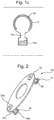
first flange 34a and/or thebody portion 34c may be flexible. This may allow the diameter of the first flange and optionally thebody portion 34c to be reduced in order for the first flange and body portion to be inserted into thebore 12 formed in thefirst component 10. Additionally or alternatively, as depicted inFigure 2 , thefirst flange 34a and/or thebody portion 34c may comprise a plurality ofslits 38. When thefirst flange 34a and thebody portion 34c are inserted into the opening or bore 12, theslits 38 may be compressed in order to reduce the diameter of thefirst flange 34a and/orbody portion 34c. - As shown in
Figure 2 , thegasket assembly 30 may comprise a plurality of retainingelements 34 configured to couple thegasket assembly 30 to thefirst component 10. For example, thegasket assembly 30 may comprise two, three or more than three retainingelements 34. Each of the retaining elements may be received within an opening or bore of the first component. - With reference to
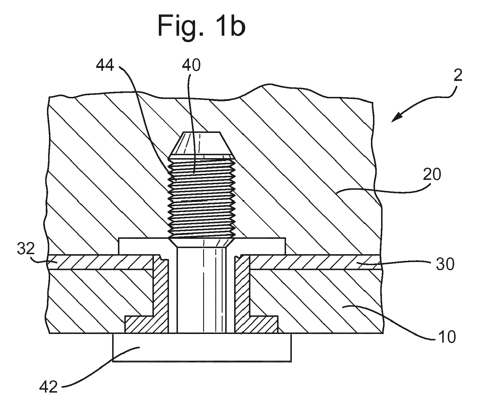
Figures 1b and1c , thebore 12 may be configured to receive afastener 40 to couple together the first andsecond components fastener 40 may comprise ahead 42 and ashank 44. Thegasket aperture 32c may be configured to align with thebore 12, such that thefastener shank 44 passes through thegasket aperture 32c. Hence, the seal created by thegasket assembly 30 may extend around thefastener 40. Thebody portion 34c may define aretainer bore 34d. Theretainer bore 34d may be aligned with thebore 12 defined in the first component and with thegasket aperture 32c. When the first component is coupled to the second component, thefastener shank 44 may be passed through theretainer bore 34d. - As depicted in
Figure 1a , a counter-bore 12a may be provided at thebore 12 on thefirst side 10a of the first component to accommodate thefirst flange 34a. The counter-bore 12a may define a shoulder and thefirst flange 34a may be arranged to abut the shoulder such that removal of the retainingelement 34 from the bore is prevented. As shown inFigure 1a , the bottom of the counter-bore may be flat, e.g. in a plane perpendicular to a central axis of the bore. However, it is equally envisaged that the bottom of the counter-bore may not be flat. For example, the bottom of the counter-bore may be angled or curved. - The
first flange 34a may be at least partially received within the counter-bore 12a. As shown inFigure 1a , thefirst flange 34a may be completely received within the counter-bore 12a such that the first flange does not protrude out of the counter-bore 12a, e.g. beyond a surface of thefirst component 10 on its first side. For example, a thickness of thefirst flange 34a may be less than or equal to a depth of the counter-bore 12. When thefastener 40 is installed, thehead 42 of the fastener may abut thefirst component 10 at thefirst side 10a. By configuring thefirst flange 34a and/or the counter-bore 12a such that the first flange does not protrude out of the counter-bore 12a, thefirst flange 34a may not interfere with the installation of thefastener 40. Additionally, by configuring thefirst flange 34a and/or the counter-bore 12a in this way, the fastener may not apply a load to the retainingelement 34 when thefirst component 10 is coupled to thesecond component 12. - The
second component 20 may comprise abore 22 configured to receive thefastener 40. At least a portion of thebore 22 may be threaded. A distal end of thefastener shank 44 may be received in thebore 22 and may be threaded into the threaded portion in order to couple thefirst component 10 to thesecond component 20. When thevehicle assembly 2 is assembled, thebore 22 may be aligned with thebore 12 of the first component, the gasket bore 32c and the retainer bore 36d. - The
second component 20 may further comprise a counter-bore 24 provided at an opening of thebore 22. Thesecond flange 32b may be at least partially received within the counter-bore. In the arrangement shown inFigure 1a , the counter-bore 24 and thesecond flange 32b are configured such that a thickness of thesecond flange 32b is less than or equal to a depth of the counter-bore 24. Hence, when thevehicle assembly 2 is assembled, and thegasket body 32 is clamped between the first andsecond components second flange 32b may be completely received within the counter-bore 24 and thesecond flange 32b may not interfere with thesecond component 20 or thegasket body 32. - At least a portion of the retaining
element 34 is deformable. For example, the retainingelement 34 may comprise a deformable portion. The deformable portion may be configured to deform, e.g. permanently deform. In particular, the deformable portion may be configured to deform from a first state, as depicted inFigure 1a , to a second state, as depicted inFigure 1b . In the first state, the retainingmember 34 is configured to couple thegasket body 32 to thefirst component 10 as described above. In the second state, the retainingelement 34 may not couple thegasket assembly 30 to thefirst component 10. - As depicted in
Figure 1b , the deformable portion may comprise thesecond flange 34b. Additionally or alternatively, the deformable portion may comprise at least a portion of thebody portion 34c and/or thefirst flange 34a. For example, the deformable portion may comprise a portion of thebody portion 34c adjacent to the first and/or second flange, such that when the deformable portion deforms the first and/or second flanges become disconnected from thebody portion 34c. - In some arrangements, the retaining
element 34 or the deformable portion of the retainingelement 34 may be configured to deform from the first state to the second state by virtue of on operating condition of thegasket assembly 30. The deformable portion may deform due to the operating temperature of thegasket assembly 30, e.g. the operating temperature of thevehicle assembly 2 in which thegasket assembly 30 is installed. For example, the deformable portion may melt, sublime, evaporate, oxidise and/or decompose, e.g. thermally decompose, due to the operating temperature of thegasket assembly 2. - The retaining
element 34 or deformable portion of the retainingelement 34 may be manufactured from a material having a melting, sublimation, evaporation, oxidation and/or decomposition temperature that is less that the operating temperature of the gasket assembly. For example, the retainingmember 34, or deformable portion may be manufactured from a polymer material, such as Nylon or polycaprolacone, a wax material, or any other suitable material. - With reference to
Figure 1c , the first component may comprise adrain channel 10c and/or achamber 10d. Thedrain channel 10c may be configured to allow the melted deformable portion to drain away from thegasket assembly 30. As depicted inFigure 1c , thefirst component 10 further comprises achamber 10d configured to receive the melted deformable portion, such that the deformable portion may be retained by thefirst component 10. The melted deformable portion may flow through the drain channel and into thechamber 10d. In alternative arrangements, thechamber 10d may be omitted and thedrain channel 10c may extend through thefirst component 10 such that the deformable portion is able to drain away out of thefirst component 10. In another alternative arrangement, thedrain channel 10c may be omitted and the deformable portion may drain directly into thechamber 10d. - In an alternative arrangement, the retaining
element 34 or the deformable portion of the retainingelement 34 may be frangible, e.g. breakable, and may be configured to fracture or shatter during operation of thevehicle assembly 2, such that the retainingelement 34 no longer couples thegasket assembly 30 to thefirst component 10 following operation of thevehicle assembly 2. For example, the deformable portion may be configured to break due to vibrations of thegasket assembly 30 during operation of thevehicle assembly 2. - In other arrangements, the deformable portion may be configured to deform during assembly of the
vehicle assembly 2, such that the retainingelement 34 no longer couples thegasket assembly 30 to thefirst component 10 following assembly. For example, the retainingmember 34 may be configured such that a length of thebody portion 34c of the retaining member may be greater than the distance between the counter bore 12 and the counter bore 24, e.g. between an opening of the counter-bore 24 and a bottom of the counter-bore 12. For example, the length of thebody portion 34c may be greater than a thickness of thegasket body 32 and the length of thebore 12 together. Hence, when the vehicle assembly is assembled, such that no gaps are present between the first component, thegasket body 32 and the second component, thefirst flange 34a may protrude out of the counter bore 12. When the retainingelement 34 is configured in this way, tightening thefastener 40 may cause the deformable portion to deform, e.g. buckle and/or fracture, from the first state to the second state as thefirst component 10 is coupled to thesecond component 12. In the second state, thefirst flange 34a may be received within the counter-bore 12, e.g. such that thefirst flange 34a does not protrude outside of the counter-bore 12. Furthermore, when the deformable portion is in the second state, the retaining member may no longer couple the gasket assembly to the first component. For example, thebody portion 34c of the retaining element may fracture during assembly of thevehicle assembly 2. Alternatively, thefirst flange 34a and/or thesecond flange 34b may fracture and/or may break away from thebody portion 34c. - With reference to
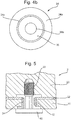
Figure 3 , the retainingelement 34 may optionally comprise one ormore grip members 36. Thegrip members 36 may extend radially inwards from thebody portion 34c of the retainingelement 34 into theretainer bore 34d. As shown inFigure 3 , thegrip members 34 may extend in a direction comprising a component in a direction of a central axis of theretainer bore 34d, e.g. towards thesecond flange 34b.Grip surfaces 36a may be provided at distal ends of each of thegrip members 36. The grip surfaces 36a may at least partially define anopening 36b configured to receive thefastener shank 44. Thegrip members 36 may be configured to couple to thefastener 40, when the fastener shank is received within the retainer bore. - As depicted in
Figure 4a , the retainingelement 34 may comprise a plurality ofgrip members 36. As shown inFigure 4a , thegrip members 36 may be arranged circumferentially about thebody portion 34c and may protrude into theretainer bore 34d. Thegrip members 36 may be separated by circumferentially extending gaps between thegrip members 36. As shown inFigure 3b , sidewalls 36c of the grip members may extend in a substantially radial direction of the retainingelement 34. - The
grip members 36 may be resilient. When theshank 44 of the fastener is inserted into theopening 36b, thegrip members 36 may be deflected in order to allow thefastener 40 to be received within theopening 36b. - Following installation of the
shank 44 into theopening 36b, the grip members 12b may grip thefastener 40, e.g. at the grip surfaces 36a, to provide a resistance against its removal. The resistance may be at least partially due to friction between the grip surfaces 36a and theshank 44. - In the alternative arrangement shown in
Figure 4b , asingle grip member 36 is provided. The single grip member extends around, e.g. completely around, the circumference of thebody portion 34c. Thegrip member 36 forms a resilient ring that may be deformed in order to allow theshank 44 to be inserted into theretainer bore 34d. - With reference to
Figure 3 , a central portion 44a of the shank may have a smaller diameter than adistal portion 44b of the shank. The central anddistal portions 44a, 44b of the shank may be separated by a shoulder orlip 44c. As described above, thegrip members 36 may be deformed in order to allow theshank 44 to be received within theopening 36b. Once thedistal portion 44b of the shank has been received within theopening 36b, e.g. such that thegrip members 36 are aligned with the central portion 44a of the shank, thegrip members 36a may spring back inwardly, due to their resilient nature, and the grip surfaces 36a may contact the central portion 44a of the shank. Thegrip members 36 may be positioned to act against theshoulder 44c to resist the removal of thefastener 40 from theretainer bore 34d. Thefastener 40 may otherwise be movable, e.g. axially movable, relative to the retainingmember 34, e.g. such that thegrip members 36 remain aligned with the central portion 44a of the shank. - With reference to
Figure 3 and5 , thegrip members 36 may comprise, or consist of, a deformable portion. The deformable portion may be configured to deform from a first state, depicted inFigure 3 , to a second state, e.g. as depicted inFigure 5 , during operation of the vehicle assembly, e.g. due to the operating condition of the gasket assembly. When the deformable portion is in the second state, thefastener shank 44 may be readily removed from theretainer bore 34d. When in the second state, the grip members may provide substantially no resistance to the removal of thefastener 40 from thevehicle assembly 2. - The grip member deformable portion may deform due to the operating temperature of the gasket assembly, e.g. the operating temperature of the vehicle assembly in which the gasket assembly is installed. For example, the deformable portion may melt, sublime, evaporate, oxidise and/or decompose, e.g. thermally decompose due to the operating temperature of the gasket assembly.
- The
grip member 36, or deformable portion may be manufactured from a material having a melting, sublimation, evaporation, oxidation and or decomposition temperature that is less that the operating temperature of the gasket assembly. For example, the grip member, or deformable portion may be manufactured from a polymer material, such as Nylon or polycaprolacone, a wax material, or any other suitable material. - In an alternative arrangement, the grip member deformable portion may be frangible, e.g. breakable, and may be configured to fracture or shatter during operation of the vehicle assembly, such that the grip member no longer couples to the fastener following operation of the vehicle assembly. For example, the deformable portion may be configured to break due to vibrations of the gasket assembly during operation of the vehicle assembly. The deformable portion of the grip member may have a natural frequency of vibration that is substantially equal to a frequency at which the vehicle assembly vibrates during operation.
- The deformable portion of the
grip member 36 may be configured to deform under substantially the same conditions as the deformable portion of the retainingelement 34. - With reference to
Figure 6 , when the retainingelement 34 comprises thegrip members 36, the retainingelement 34 may be prevented from decoupling from thefirst component 10 due to the coupling between thegrip members 36 and thefastener 40. Hence, when the retainingelement 34 comprises thegrip members 36, thefirst flange 34a may be omitted from the retainingelement 34. - With reference to
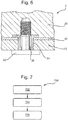
Figure 7 , amethod 700 of replacing a replacing a gasket of a vehicle assembly, according to arrangements of the present disclosure, will now be described. Themethod 700 may be performed when maintaining thevehicle assembly 2 or any other vehicle assembly comprising thegasket assembly 30. - The method comprises a
first step 702, in which thevehicle assembly 2 is operated such that thegasket assembly 30 reaches a predetermined operating condition. The predetermined operating condition may be a standard operating condition that thegasket assembly 30 has been designed to operate at within thevehicle assembly 2. Due to operating at the predetermined operating condition, a deformable portion of the retainingelement 34 of thegasket assembly 30 may be deformed from the first state to the second state. Hence, thegasket assembly 30 may no longer remain coupled to thefirst component 10 when thevehicle assembly 2 is disassembled. - In a
second step 704 of themethod 700, thegasket assembly 30 may be replaced with a replacement gasket. The replacement gasket may not comprise a retaining element. - In some arrangements, the
fastener 40 may be a single use fastener. The method may comprise athird step 706, in which the fastener is replaced with a replacement fastener. Alternatively, the original fastener may be re-used. - The following additional numbered statements of invention are included within this specification and form part of the present disclosure.
- Statement 1. A seal assembly for an assembly of a vehicle, the seal assembly comprising:
- a seal configured to create a seal between first and second components of the vehicle assembly; and
- a retaining element configured to couple the seal to the first component prior to assembly of the vehicle assembly, wherein at least a portion of the retaining element is deformable and is configured to deform from a first state to a second state during installation or use of the seal assembly, such that after said deformation the retaining element no longer couples the seal to the first component.
-
Statement 2. The seal assembly of statement 1, wherein the retaining element or portion thereof is configured to deform from the first state to the second state due to the operating temperature of the seal assembly. - Statement 3. The seal assembly of
statement 1 or 2, wherein the retaining element or portion thereof is frangible and is configured to break when the seal assembly is installed into the vehicle assembly. - Statement 4. The seal assembly of any of the preceding statements, wherein the retaining element is configured to be at least partially received within a bore formed in the first component.
- Statement 5. The seal assembly of any of the preceding statements, wherein the retaining element is configured to extend through a bore defined in the first component.
- Statement 6. The seal assembly of any of the preceding statements, wherein the seal defines a seal aperture configured to receive a fastener for coupling the first component to the second component, wherein the retaining element extends through the seal aperture.
- Statement 7. The seal assembly of any of the preceding statements, wherein the retaining element defines a retainer aperture configured to receive a fastener.
- Statement 8. The seal assembly of statement 6 and 7, wherein the retainer aperture is aligned with the seal aperture.
- Statement 9. The seal assembly of any of statements 7 or 8, wherein the retaining element further comprises a grip member, wherein the grip member is configured to couple to the fastener received within the retainer aperture and provide resistance against the removal of the fastener from the retainer aperture.
-
Statement 10. The seal assembly of statement 9, wherein at least a portion of the grip member is configured to deform between a first state and a second state by virtue of the operating condition of the seal assembly such that the fastener may be removed from the retainer aperture when the further grip member or portion thereof is in the second state. - Statement 11. The seal assembly of
statement 10, wherein the grip member or portion thereof is configured to deform under substantially the same conditions as the retaining element of portion thereof. -
Statement 12. The seal assembly of any of the preceding statements, wherein the retaining element is integral with the seal. - Statement 13. The seal assembly of any of the preceding statements, wherein the retaining element comprises a first flange, a second flange and a body portion extending between the first and second flanges.
- Statement 14. The seal assembly of statement 13, wherein the body portion of the retaining element is configured to extend through a bore of the first component such that the first flange is arranged on a first side of the bore, and the second flange is arranged on a second side of the bore.
- Statement 15. The seal assembly of statement 13 or 14, wherein the first flange and/or the body portion is flexible.
- Statement 16. The seal assembly according to any of statements 13 to 15, wherein the first flange and/or the body portion comprise a plurality of slits configured to allow the diameter of the first flange be reduced.
- Statement 17. An assembly for a vehicle comprising:
- a seal assembly according to any of the preceding statements; and
- the first component.
- Statement 18. The assembly of statement 17 when dependent on any of statements 13 to 16, wherein the first component comprises a counter-bore, and wherein the first flange of the retaining element is at least partially received within the counter-bore.
- Statement 19. The assembly of statement 17 or 18 when dependent on any of statements 13 to 16, wherein the seal is arranged between the second flange of the retaining element and the first component.
-
Statement 20. The assembly of any of statements 17 to 19 further comprising a fastener configured to couple the first component to the second component of the vehicle assembly. - Statement 21. The assembly of
statement 20 when depending on any of statements 13 to 16, wherein a head of the fastener has a larger diameter than the first flange of the retaining element. -
Statement 22. The assembly ofstatement 20 or 21, wherein the fastener comprises a shank having a mid portion and a distal portion, the mid portion having a smaller diameter than the distal portion, the mid portion and the distal portion being separated by a shoulder; wherein the retaining member acts against the shoulder in order to provide resistance against the removal of the fastener. - Statement 23. The assembly of any of statements 17 to 22, wherein the first component comprises a drain channel configured to allow a melted portion of the retaining element to drain away from the seal.
-
Statement 24. The assembly of any of statements 17 to 23, wherein the first component comprises a chamber, the chamber being configured such that a melted portion of the retaining element is received within the chamber. - Statement 25. The assembly of any of statements 17 to 24, wherein the first component comprises a bore configured to receive a fastener to couple the first component to a second component of the vehicle assembly, wherein the retaining element is at least partially received within the bore.
- Statement 26. The assembly of any of statements 17 to 25, wherein the vehicle assembly further comprises a second component.
- Statement 27. The assembly of statement 26, wherein the second component comprises a bore configured to receive a fastener to couple the first component to the second component.
- Statement 28. The assembly of statement 26 or 27, wherein the second component comprises a counter-bore configured to receive a portion of the retaining element.
- Statement 29. The assembly of any of statements 26 to 28, wherein the second component comprises a drain channel configured to allow a melted portion of the retaining element to drain away from the seal.
-
Statement 30. A method for a seal for an assembly of a vehicle, wherein the vehicle assembly comprises a first component, a second component and a seal assembly, the seal assembly comprising:- the seal configured to create a seal between the first component and the second component of the vehicle assembly; and
- a retaining element configured to couple the seal to the first component prior to assembly of the vehicle assembly, wherein at least a portion of the retaining element is deformable and is configured to deform from a first state to a second state during installation or use of the seal assembly, such that after said deformation the seal is no longer coupled to the first component, wherein the method comprises:
- installing or using the seal within the vehicle assembly such that the retaining element or portion thereof deforms from the first state to the second state.
- Statement 31. The method of
statement 30, wherein the method further comprises:- replacing the seal assembly with a replacement seal, wherein the replacement seal does not comprise a retaining element.
- It will be appreciated by those skilled in the art that although the invention has been described by way of example, with reference to one or more examples, it is not limited to the disclosed examples and alternative examples may be constructed without departing from the scope of the invention as defined by the appended claims.
Claims (15)
- A seal assembly for an assembly of a vehicle, the seal assembly comprising:a seal configured to create a seal between first and second components of the vehicle assembly; anda retaining element configured to couple the seal to the first component prior to assembly of the vehicle assembly, wherein at least a portion of the retaining element is deformable and is configured to deform from a first state to a second state during installation or use of the seal assembly, such that after said deformation the retaining element no longer couples the seal to the first component.
- The seal assembly of claim 1, wherein the retaining element or portion thereof is configured to deform from the first state to the second state due to the operating temperature of the seal assembly.
- The seal assembly of claim 1 or 2, wherein the retaining element or portion thereof is frangible and is configured to break when the seal assembly is installed into the vehicle assembly.
- The seal assembly of any of the preceding claims, wherein the seal defines a seal aperture configured to receive a fastener for coupling the first component to the second component, wherein the retaining element extends through the seal aperture and, wherein the retaining element defines a retainer aperture configured to receive a fastener.
- The seal assembly of claim 4, wherein the retaining element further comprises a grip member, wherein the grip member is configured to couple to the fastener received within the retainer aperture and provide resistance against the removal of the fastener from the retainer aperture.
- The seal assembly of claim 5, wherein at least a portion of the grip member is configured to deform between a first state and a second state by virtue of the operating condition of the seal assembly such that the fastener may be removed from the retainer aperture when the further grip member or portion thereof is in the second state.
- The seal assembly of any of the preceding claims, wherein the retaining element is integral with the seal.
- An assembly for a vehicle comprising:a seal assembly according to any of the preceding claims; andthe first component.
- The assembly of claim 8, wherein the first component comprises a drain channel configured to allow a melted portion of the retaining element to drain away from the seal.
- The assembly of claim 8 or 9, wherein the first component comprises a chamber, the chamber being configured such that a melted portion of the retaining element is received within the chamber.
- The assembly of any of claims 8 to 10, wherein the first component comprises a bore configured to receive a fastener to couple the first component to a second component of the vehicle assembly, wherein the retaining element is at least partially received within the bore.
- The assembly of any of claims 8 to 11, wherein the vehicle assembly further comprises the second component
- The assembly of claim 12, wherein the second component comprises a drain channel configured to allow a melted portion of the retaining element to drain away from the seal.
- A method for a seal for an assembly of a vehicle, wherein the vehicle assembly comprises a first component, a second component and a seal assembly, the seal assembly comprising:the seal configured to create a seal between the first component and the second component of the vehicle assembly; anda retaining element configured to couple the seal to the first component prior to assembly of the vehicle assembly, wherein at least a portion of the retaining element is deformable and is configured to deform from a first state to a second state during installation or use of the seal assembly, such that after said deformation the seal is no longer coupled to the first component, wherein the method comprises:installing or using the seal within the vehicle assembly such that the retaining element or portion thereof deforms from the first state to the second state.
- The method of claim 14, wherein the method further comprises:replacing the seal assembly with a replacement seal, wherein the replacement seal does not comprise a retaining element.
Applications Claiming Priority (1)
| Application Number | Priority Date | Filing Date | Title |
|---|---|---|---|
| GB1705614.4A GB2561233B (en) | 2017-04-07 | 2017-04-07 | A Gasket Assembly |
Publications (2)
| Publication Number | Publication Date |
|---|---|
| EP3385576A1 true EP3385576A1 (en) | 2018-10-10 |
| EP3385576B1 EP3385576B1 (en) | 2020-04-01 |
Family
ID=58744680
Family Applications (1)
| Application Number | Title | Priority Date | Filing Date |
|---|---|---|---|
| EP18154515.3A Not-in-force EP3385576B1 (en) | 2017-04-07 | 2018-01-31 | A gasket assembly |
Country Status (5)
| Country | Link |
|---|---|
| US (1) | US10641312B2 (en) |
| EP (1) | EP3385576B1 (en) |
| CN (1) | CN108691880B (en) |
| GB (1) | GB2561233B (en) |
| RU (1) | RU2018111526A (en) |
Families Citing this family (7)
| Publication number | Priority date | Publication date | Assignee | Title |
|---|---|---|---|---|
| US20200147768A1 (en) * | 2018-11-13 | 2020-05-14 | Katerra Inc. | Captive fastener |
| GB201820718D0 (en) * | 2018-12-19 | 2019-01-30 | Agco Int Gmbh | Sealing device |
| US11462854B2 (en) * | 2019-11-12 | 2022-10-04 | Aptiv Technologies Limited | Electrical connector with a mounting flange and method of assembling same |
| JP7657830B2 (en) * | 2020-05-12 | 2025-04-07 | アイコール・システムズ・インク | Seal retainer for component assembly and method for attaching components to flow control device |
| US12589474B2 (en) * | 2020-05-12 | 2026-03-31 | Ichor Systems, Inc. | Seal insertion tool for a fluid delivery module and method of installing a seal into a fluid delivery module |
| DE102020207094A1 (en) * | 2020-06-05 | 2021-12-09 | Volkswagen Aktiengesellschaft | Arrangement of two sealing partners |
| US11850810B2 (en) * | 2021-05-18 | 2023-12-26 | The Boeing Company | Skin-bonded threaded inserts, sandwich panels including the same, and related methods |
Citations (4)
| Publication number | Priority date | Publication date | Assignee | Title |
|---|---|---|---|---|
| US20030133793A1 (en) * | 2002-01-17 | 2003-07-17 | Srikanth Vedantam | Cloth seal for an inner compressor discharge case and methods of locating the seal in situ |
| AU2007201648A1 (en) * | 2007-04-16 | 2008-11-06 | Kevin Brett Duck | Apparatus for gasket installation |
| WO2011023425A1 (en) * | 2009-08-31 | 2011-03-03 | Federal-Mogul Sealing Systems Gmbh | Cover mounting unit |
| DE102012107539A1 (en) * | 2012-08-16 | 2014-02-20 | Elringklinger Ag | Single-layer metallic gasket for installation between seal surfaces of flanges in e.g. exhaust gas manifold of internal combustion engine, has layer region releasing screw hole, back-folded on seal layer and bent at line spaced from recess |
Family Cites Families (12)
| Publication number | Priority date | Publication date | Assignee | Title |
|---|---|---|---|---|
| US4784396A (en) | 1987-06-01 | 1988-11-15 | Ford Motor Company | Retaining clip and gasket for engine subassembly |
| US5505466A (en) | 1992-12-18 | 1996-04-09 | Dana Corporation | Cylinder head gasket with retaining ring and spring seal |
| US5681064A (en) | 1995-07-07 | 1997-10-28 | Ewal Manufacturing Co., Inc. | Gasket retainer |
| JP3122386B2 (en) | 1996-07-16 | 2001-01-09 | シーケーディ株式会社 | Gasket holder |
| US5890719A (en) | 1996-08-27 | 1999-04-06 | Parker-Hannifin Corporation | Combination metal and elastomer cylinder head gasket |
| US5735533A (en) * | 1997-01-03 | 1998-04-07 | Eg&G Pressure Science, Inc. | Cavity depth increasing retainer |
| JP2000097223A (en) * | 1998-09-21 | 2000-04-04 | Nitto Seiko Co Ltd | Washer and washer built-in support structure |
| WO2000071922A1 (en) | 1999-05-13 | 2000-11-30 | General Components, Inc. | Gasket retainer clip |
| US8632073B2 (en) * | 2007-06-08 | 2014-01-21 | Raytheon Company | Methods and apparatus for a seal |
| CN201916323U (en) * | 2011-01-11 | 2011-08-03 | 中国重汽集团济南动力有限公司 | Anti-dropping shock-absorption bolt assembly |
| CN102606732A (en) * | 2011-01-20 | 2012-07-25 | 昆达电脑科技(昆山)有限公司 | Anti-shedding waterproof washer |
| GB2536471A (en) * | 2015-03-18 | 2016-09-21 | Airbus Operations Ltd | Self-sealing fixing element |
-
2017
- 2017-04-07 GB GB1705614.4A patent/GB2561233B/en not_active Expired - Fee Related
-
2018
- 2018-01-31 EP EP18154515.3A patent/EP3385576B1/en not_active Not-in-force
- 2018-03-09 US US15/917,228 patent/US10641312B2/en not_active Expired - Fee Related
- 2018-03-30 RU RU2018111526A patent/RU2018111526A/en not_active Application Discontinuation
- 2018-04-04 CN CN201810301391.9A patent/CN108691880B/en not_active Expired - Fee Related
Patent Citations (4)
| Publication number | Priority date | Publication date | Assignee | Title |
|---|---|---|---|---|
| US20030133793A1 (en) * | 2002-01-17 | 2003-07-17 | Srikanth Vedantam | Cloth seal for an inner compressor discharge case and methods of locating the seal in situ |
| AU2007201648A1 (en) * | 2007-04-16 | 2008-11-06 | Kevin Brett Duck | Apparatus for gasket installation |
| WO2011023425A1 (en) * | 2009-08-31 | 2011-03-03 | Federal-Mogul Sealing Systems Gmbh | Cover mounting unit |
| DE102012107539A1 (en) * | 2012-08-16 | 2014-02-20 | Elringklinger Ag | Single-layer metallic gasket for installation between seal surfaces of flanges in e.g. exhaust gas manifold of internal combustion engine, has layer region releasing screw hole, back-folded on seal layer and bent at line spaced from recess |
Also Published As
| Publication number | Publication date |
|---|---|
| GB201705614D0 (en) | 2017-05-24 |
| CN108691880B (en) | 2021-09-10 |
| CN108691880A (en) | 2018-10-23 |
| RU2018111526A (en) | 2019-10-03 |
| EP3385576B1 (en) | 2020-04-01 |
| GB2561233A (en) | 2018-10-10 |
| US20180291946A1 (en) | 2018-10-11 |
| US10641312B2 (en) | 2020-05-05 |
| GB2561233B (en) | 2020-01-15 |
Similar Documents
| Publication | Publication Date | Title |
|---|---|---|
| EP3385576B1 (en) | A gasket assembly | |
| US7893572B2 (en) | Motor attachment assembly for plastic post isolation system | |
| CN107781270B (en) | Screw with washer | |
| EP1956274A1 (en) | Installation structure of bore plug | |
| US10221879B2 (en) | Panel mount fastener having an outer sleeve with a collapsible end portion | |
| CN112145687B (en) | Assembly plug | |
| EP3330555A2 (en) | Locking boot for ball joint | |
| WO2015107971A1 (en) | Device for affixing lower-level member and fluid control device provided with same | |
| EP3109554B1 (en) | Fuel supply nozzle unit having sealing structure | |
| US9708933B2 (en) | Plug assembly with retaining element | |
| CN105074269B (en) | Torque rod | |
| US20080145180A1 (en) | Combination of a screw member and a sleeve and also a method of producing such a combination | |
| US11686338B2 (en) | Blind rivet insert, a component with an installed blind rivet insert and method for installing such a blind rivet insert in a component opening | |
| EP1950472B1 (en) | Sealing device | |
| JP5133155B2 (en) | Shaft removal prevention structure | |
| MXPA05001560A (en) | Spark plug tube seal. | |
| EP3623669B1 (en) | Mechanical seal | |
| US6840865B2 (en) | Slip seal retainer and stop | |
| CN107477062B (en) | Fastener assembly | |
| CN104685231B (en) | For moving the terminal of transmission remotely control component | |
| CN110088429B (en) | Method for installing a camshaft in a bearing shell and a camshaft | |
| EP1950473B1 (en) | Carbon dioxide gas sealing enclosed device | |
| US20100172713A1 (en) | Self locking floating fastener | |
| US11752454B2 (en) | Filter device | |
| US20150037117A1 (en) | Prevailing torque locknut |
Legal Events
| Date | Code | Title | Description |
|---|---|---|---|
| PUAI | Public reference made under article 153(3) epc to a published international application that has entered the european phase |
Free format text: ORIGINAL CODE: 0009012 |
|
| STAA | Information on the status of an ep patent application or granted ep patent |
Free format text: STATUS: THE APPLICATION HAS BEEN PUBLISHED |
|
| AK | Designated contracting states |
Kind code of ref document: A1 Designated state(s): AL AT BE BG CH CY CZ DE DK EE ES FI FR GB GR HR HU IE IS IT LI LT LU LV MC MK MT NL NO PL PT RO RS SE SI SK SM TR |
|
| AX | Request for extension of the european patent |
Extension state: BA ME |
|
| STAA | Information on the status of an ep patent application or granted ep patent |
Free format text: STATUS: REQUEST FOR EXAMINATION WAS MADE |
|
| 17P | Request for examination filed |
Effective date: 20181010 |
|
| RBV | Designated contracting states (corrected) |
Designated state(s): AL AT BE BG CH CY CZ DE DK EE ES FI FR GB GR HR HU IE IS IT LI LT LU LV MC MK MT NL NO PL PT RO RS SE SI SK SM TR |
|
| GRAP | Despatch of communication of intention to grant a patent |
Free format text: ORIGINAL CODE: EPIDOSNIGR1 |
|
| STAA | Information on the status of an ep patent application or granted ep patent |
Free format text: STATUS: GRANT OF PATENT IS INTENDED |
|
| INTG | Intention to grant announced |
Effective date: 20191017 |
|
| GRAS | Grant fee paid |
Free format text: ORIGINAL CODE: EPIDOSNIGR3 |
|
| GRAA | (expected) grant |
Free format text: ORIGINAL CODE: 0009210 |
|
| STAA | Information on the status of an ep patent application or granted ep patent |
Free format text: STATUS: THE PATENT HAS BEEN GRANTED |
|
| AK | Designated contracting states |
Kind code of ref document: B1 Designated state(s): AL AT BE BG CH CY CZ DE DK EE ES FI FR GB GR HR HU IE IS IT LI LT LU LV MC MK MT NL NO PL PT RO RS SE SI SK SM TR |
|
| REG | Reference to a national code |
Ref country code: GB Ref legal event code: FG4D |
|
| REG | Reference to a national code |
Ref country code: AT Ref legal event code: REF Ref document number: 1251764 Country of ref document: AT Kind code of ref document: T Effective date: 20200415 Ref country code: CH Ref legal event code: EP |
|
| REG | Reference to a national code |
Ref country code: DE Ref legal event code: R096 Ref document number: 602018003313 Country of ref document: DE |
|
| REG | Reference to a national code |
Ref country code: IE Ref legal event code: FG4D |
|
| PG25 | Lapsed in a contracting state [announced via postgrant information from national office to epo] |
Ref country code: BG Free format text: LAPSE BECAUSE OF FAILURE TO SUBMIT A TRANSLATION OF THE DESCRIPTION OR TO PAY THE FEE WITHIN THE PRESCRIBED TIME-LIMIT Effective date: 20200701 |
|
| REG | Reference to a national code |
Ref country code: NL Ref legal event code: MP Effective date: 20200401 |
|
| REG | Reference to a national code |
Ref country code: LT Ref legal event code: MG4D |
|
| PG25 | Lapsed in a contracting state [announced via postgrant information from national office to epo] |
Ref country code: NO Free format text: LAPSE BECAUSE OF FAILURE TO SUBMIT A TRANSLATION OF THE DESCRIPTION OR TO PAY THE FEE WITHIN THE PRESCRIBED TIME-LIMIT Effective date: 20200701 Ref country code: GR Free format text: LAPSE BECAUSE OF FAILURE TO SUBMIT A TRANSLATION OF THE DESCRIPTION OR TO PAY THE FEE WITHIN THE PRESCRIBED TIME-LIMIT Effective date: 20200702 Ref country code: IS Free format text: LAPSE BECAUSE OF FAILURE TO SUBMIT A TRANSLATION OF THE DESCRIPTION OR TO PAY THE FEE WITHIN THE PRESCRIBED TIME-LIMIT Effective date: 20200801 Ref country code: CZ Free format text: LAPSE BECAUSE OF FAILURE TO SUBMIT A TRANSLATION OF THE DESCRIPTION OR TO PAY THE FEE WITHIN THE PRESCRIBED TIME-LIMIT Effective date: 20200401 Ref country code: FI Free format text: LAPSE BECAUSE OF FAILURE TO SUBMIT A TRANSLATION OF THE DESCRIPTION OR TO PAY THE FEE WITHIN THE PRESCRIBED TIME-LIMIT Effective date: 20200401 Ref country code: SE Free format text: LAPSE BECAUSE OF FAILURE TO SUBMIT A TRANSLATION OF THE DESCRIPTION OR TO PAY THE FEE WITHIN THE PRESCRIBED TIME-LIMIT Effective date: 20200401 Ref country code: PT Free format text: LAPSE BECAUSE OF FAILURE TO SUBMIT A TRANSLATION OF THE DESCRIPTION OR TO PAY THE FEE WITHIN THE PRESCRIBED TIME-LIMIT Effective date: 20200817 Ref country code: LT Free format text: LAPSE BECAUSE OF FAILURE TO SUBMIT A TRANSLATION OF THE DESCRIPTION OR TO PAY THE FEE WITHIN THE PRESCRIBED TIME-LIMIT Effective date: 20200401 Ref country code: NL Free format text: LAPSE BECAUSE OF FAILURE TO SUBMIT A TRANSLATION OF THE DESCRIPTION OR TO PAY THE FEE WITHIN THE PRESCRIBED TIME-LIMIT Effective date: 20200401 |
|
| REG | Reference to a national code |
Ref country code: AT Ref legal event code: MK05 Ref document number: 1251764 Country of ref document: AT Kind code of ref document: T Effective date: 20200401 |
|
| PG25 | Lapsed in a contracting state [announced via postgrant information from national office to epo] |
Ref country code: HR Free format text: LAPSE BECAUSE OF FAILURE TO SUBMIT A TRANSLATION OF THE DESCRIPTION OR TO PAY THE FEE WITHIN THE PRESCRIBED TIME-LIMIT Effective date: 20200401 Ref country code: RS Free format text: LAPSE BECAUSE OF FAILURE TO SUBMIT A TRANSLATION OF THE DESCRIPTION OR TO PAY THE FEE WITHIN THE PRESCRIBED TIME-LIMIT Effective date: 20200401 Ref country code: LV Free format text: LAPSE BECAUSE OF FAILURE TO SUBMIT A TRANSLATION OF THE DESCRIPTION OR TO PAY THE FEE WITHIN THE PRESCRIBED TIME-LIMIT Effective date: 20200401 |
|
| PG25 | Lapsed in a contracting state [announced via postgrant information from national office to epo] |
Ref country code: AL Free format text: LAPSE BECAUSE OF FAILURE TO SUBMIT A TRANSLATION OF THE DESCRIPTION OR TO PAY THE FEE WITHIN THE PRESCRIBED TIME-LIMIT Effective date: 20200401 |
|
| REG | Reference to a national code |
Ref country code: DE Ref legal event code: R097 Ref document number: 602018003313 Country of ref document: DE Ref country code: DE Ref legal event code: R082 Ref document number: 602018003313 Country of ref document: DE Representative=s name: HL KEMPNER PATENTANWALT, RECHTSANWALT, SOLICIT, DE Ref country code: DE Ref legal event code: R082 Ref document number: 602018003313 Country of ref document: DE Representative=s name: HL KEMPNER PATENTANWAELTE, SOLICITORS (ENGLAND, DE Ref country code: DE Ref legal event code: R082 Ref document number: 602018003313 Country of ref document: DE Representative=s name: HL KEMPNER PARTG MBB, DE |
|
| PG25 | Lapsed in a contracting state [announced via postgrant information from national office to epo] |
Ref country code: IT Free format text: LAPSE BECAUSE OF FAILURE TO SUBMIT A TRANSLATION OF THE DESCRIPTION OR TO PAY THE FEE WITHIN THE PRESCRIBED TIME-LIMIT Effective date: 20200401 Ref country code: RO Free format text: LAPSE BECAUSE OF FAILURE TO SUBMIT A TRANSLATION OF THE DESCRIPTION OR TO PAY THE FEE WITHIN THE PRESCRIBED TIME-LIMIT Effective date: 20200401 Ref country code: ES Free format text: LAPSE BECAUSE OF FAILURE TO SUBMIT A TRANSLATION OF THE DESCRIPTION OR TO PAY THE FEE WITHIN THE PRESCRIBED TIME-LIMIT Effective date: 20200401 Ref country code: DK Free format text: LAPSE BECAUSE OF FAILURE TO SUBMIT A TRANSLATION OF THE DESCRIPTION OR TO PAY THE FEE WITHIN THE PRESCRIBED TIME-LIMIT Effective date: 20200401 Ref country code: SM Free format text: LAPSE BECAUSE OF FAILURE TO SUBMIT A TRANSLATION OF THE DESCRIPTION OR TO PAY THE FEE WITHIN THE PRESCRIBED TIME-LIMIT Effective date: 20200401 Ref country code: EE Free format text: LAPSE BECAUSE OF FAILURE TO SUBMIT A TRANSLATION OF THE DESCRIPTION OR TO PAY THE FEE WITHIN THE PRESCRIBED TIME-LIMIT Effective date: 20200401 Ref country code: AT Free format text: LAPSE BECAUSE OF FAILURE TO SUBMIT A TRANSLATION OF THE DESCRIPTION OR TO PAY THE FEE WITHIN THE PRESCRIBED TIME-LIMIT Effective date: 20200401 |
|
| PLBE | No opposition filed within time limit |
Free format text: ORIGINAL CODE: 0009261 |
|
| STAA | Information on the status of an ep patent application or granted ep patent |
Free format text: STATUS: NO OPPOSITION FILED WITHIN TIME LIMIT |
|
| PG25 | Lapsed in a contracting state [announced via postgrant information from national office to epo] |
Ref country code: SK Free format text: LAPSE BECAUSE OF FAILURE TO SUBMIT A TRANSLATION OF THE DESCRIPTION OR TO PAY THE FEE WITHIN THE PRESCRIBED TIME-LIMIT Effective date: 20200401 Ref country code: PL Free format text: LAPSE BECAUSE OF FAILURE TO SUBMIT A TRANSLATION OF THE DESCRIPTION OR TO PAY THE FEE WITHIN THE PRESCRIBED TIME-LIMIT Effective date: 20200401 |
|
| 26N | No opposition filed |
Effective date: 20210112 |
|
| PG25 | Lapsed in a contracting state [announced via postgrant information from national office to epo] |
Ref country code: SI Free format text: LAPSE BECAUSE OF FAILURE TO SUBMIT A TRANSLATION OF THE DESCRIPTION OR TO PAY THE FEE WITHIN THE PRESCRIBED TIME-LIMIT Effective date: 20200401 |
|
| PG25 | Lapsed in a contracting state [announced via postgrant information from national office to epo] |
Ref country code: MC Free format text: LAPSE BECAUSE OF FAILURE TO SUBMIT A TRANSLATION OF THE DESCRIPTION OR TO PAY THE FEE WITHIN THE PRESCRIBED TIME-LIMIT Effective date: 20200401 |
|
| REG | Reference to a national code |
Ref country code: CH Ref legal event code: PL |
|
| PG25 | Lapsed in a contracting state [announced via postgrant information from national office to epo] |
Ref country code: LU Free format text: LAPSE BECAUSE OF NON-PAYMENT OF DUE FEES Effective date: 20210131 |
|
| REG | Reference to a national code |
Ref country code: BE Ref legal event code: MM Effective date: 20210131 |
|
| PG25 | Lapsed in a contracting state [announced via postgrant information from national office to epo] |
Ref country code: FR Free format text: LAPSE BECAUSE OF NON-PAYMENT OF DUE FEES Effective date: 20210131 |
|
| PG25 | Lapsed in a contracting state [announced via postgrant information from national office to epo] |
Ref country code: LI Free format text: LAPSE BECAUSE OF NON-PAYMENT OF DUE FEES Effective date: 20210131 Ref country code: CH Free format text: LAPSE BECAUSE OF NON-PAYMENT OF DUE FEES Effective date: 20210131 |
|
| PG25 | Lapsed in a contracting state [announced via postgrant information from national office to epo] |
Ref country code: IE Free format text: LAPSE BECAUSE OF NON-PAYMENT OF DUE FEES Effective date: 20210131 |
|
| PG25 | Lapsed in a contracting state [announced via postgrant information from national office to epo] |
Ref country code: BE Free format text: LAPSE BECAUSE OF NON-PAYMENT OF DUE FEES Effective date: 20210131 |
|
| PG25 | Lapsed in a contracting state [announced via postgrant information from national office to epo] |
Ref country code: CY Free format text: LAPSE BECAUSE OF FAILURE TO SUBMIT A TRANSLATION OF THE DESCRIPTION OR TO PAY THE FEE WITHIN THE PRESCRIBED TIME-LIMIT Effective date: 20200401 |
|
| P01 | Opt-out of the competence of the unified patent court (upc) registered |
Effective date: 20230620 |
|
| PG25 | Lapsed in a contracting state [announced via postgrant information from national office to epo] |
Ref country code: HU Free format text: LAPSE BECAUSE OF FAILURE TO SUBMIT A TRANSLATION OF THE DESCRIPTION OR TO PAY THE FEE WITHIN THE PRESCRIBED TIME-LIMIT; INVALID AB INITIO Effective date: 20180131 |
|
| PGFP | Annual fee paid to national office [announced via postgrant information from national office to epo] |
Ref country code: GB Payment date: 20231218 Year of fee payment: 7 |
|
| PG25 | Lapsed in a contracting state [announced via postgrant information from national office to epo] |
Ref country code: MK Free format text: LAPSE BECAUSE OF FAILURE TO SUBMIT A TRANSLATION OF THE DESCRIPTION OR TO PAY THE FEE WITHIN THE PRESCRIBED TIME-LIMIT Effective date: 20200401 |
|
| PGFP | Annual fee paid to national office [announced via postgrant information from national office to epo] |
Ref country code: DE Payment date: 20231215 Year of fee payment: 7 |
|
| PG25 | Lapsed in a contracting state [announced via postgrant information from national office to epo] |
Ref country code: MT Free format text: LAPSE BECAUSE OF FAILURE TO SUBMIT A TRANSLATION OF THE DESCRIPTION OR TO PAY THE FEE WITHIN THE PRESCRIBED TIME-LIMIT Effective date: 20200401 |
|
| REG | Reference to a national code |
Ref country code: DE Ref legal event code: R119 Ref document number: 602018003313 Country of ref document: DE |
|
| GBPC | Gb: european patent ceased through non-payment of renewal fee |
Effective date: 20250131 |
|
| PG25 | Lapsed in a contracting state [announced via postgrant information from national office to epo] |
Ref country code: DE Free format text: LAPSE BECAUSE OF NON-PAYMENT OF DUE FEES Effective date: 20250801 |
|
| PG25 | Lapsed in a contracting state [announced via postgrant information from national office to epo] |
Ref country code: GB Free format text: LAPSE BECAUSE OF NON-PAYMENT OF DUE FEES Effective date: 20250131 |
|
| PG25 | Lapsed in a contracting state [announced via postgrant information from national office to epo] |
Ref country code: TR Free format text: LAPSE BECAUSE OF FAILURE TO SUBMIT A TRANSLATION OF THE DESCRIPTION OR TO PAY THE FEE WITHIN THE PRESCRIBED TIME-LIMIT Effective date: 20200401 |