EP3385571A1 - Two-degree-of-freedom drive mechanism - Google Patents
Two-degree-of-freedom drive mechanism Download PDFInfo
- Publication number
- EP3385571A1 EP3385571A1 EP16870856.8A EP16870856A EP3385571A1 EP 3385571 A1 EP3385571 A1 EP 3385571A1 EP 16870856 A EP16870856 A EP 16870856A EP 3385571 A1 EP3385571 A1 EP 3385571A1
- Authority
- EP
- European Patent Office
- Prior art keywords
- rotational axis
- link member
- drive mechanism
- end portion
- driven body
- Prior art date
- Legal status (The legal status is an assumption and is not a legal conclusion. Google has not performed a legal analysis and makes no representation as to the accuracy of the status listed.)
- Granted
Links
Images




Classifications
-
- B—PERFORMING OPERATIONS; TRANSPORTING
- B25—HAND TOOLS; PORTABLE POWER-DRIVEN TOOLS; MANIPULATORS
- B25J—MANIPULATORS; CHAMBERS PROVIDED WITH MANIPULATION DEVICES
- B25J17/00—Joints
- B25J17/02—Wrist joints
- B25J17/0258—Two-dimensional joints
- B25J17/0275—Universal joints, e.g. Hooke, Cardan, ball joints
-
- F—MECHANICAL ENGINEERING; LIGHTING; HEATING; WEAPONS; BLASTING
- F16—ENGINEERING ELEMENTS AND UNITS; GENERAL MEASURES FOR PRODUCING AND MAINTAINING EFFECTIVE FUNCTIONING OF MACHINES OR INSTALLATIONS; THERMAL INSULATION IN GENERAL
- F16H—GEARING
- F16H21/00—Gearings comprising primarily only links or levers, with or without slides
- F16H21/02—Gearings comprising primarily only links or levers, with or without slides the movements of two or more independently-moving members being combined into a single movement
-
- B—PERFORMING OPERATIONS; TRANSPORTING
- B25—HAND TOOLS; PORTABLE POWER-DRIVEN TOOLS; MANIPULATORS
- B25J—MANIPULATORS; CHAMBERS PROVIDED WITH MANIPULATION DEVICES
- B25J17/00—Joints
-
- B—PERFORMING OPERATIONS; TRANSPORTING
- B25—HAND TOOLS; PORTABLE POWER-DRIVEN TOOLS; MANIPULATORS
- B25J—MANIPULATORS; CHAMBERS PROVIDED WITH MANIPULATION DEVICES
- B25J17/00—Joints
- B25J17/02—Wrist joints
- B25J17/0258—Two-dimensional joints
- B25J17/0266—Two-dimensional joints comprising more than two actuating or connecting rods
-
- B—PERFORMING OPERATIONS; TRANSPORTING
- B25—HAND TOOLS; PORTABLE POWER-DRIVEN TOOLS; MANIPULATORS
- B25J—MANIPULATORS; CHAMBERS PROVIDED WITH MANIPULATION DEVICES
- B25J9/00—Program-controlled manipulators
- B25J9/10—Program-controlled manipulators characterised by positioning means for manipulator elements
- B25J9/106—Program-controlled manipulators characterised by positioning means for manipulator elements with articulated links
-
- B—PERFORMING OPERATIONS; TRANSPORTING
- B25—HAND TOOLS; PORTABLE POWER-DRIVEN TOOLS; MANIPULATORS
- B25J—MANIPULATORS; CHAMBERS PROVIDED WITH MANIPULATION DEVICES
- B25J9/00—Program-controlled manipulators
- B25J9/10—Program-controlled manipulators characterised by positioning means for manipulator elements
- B25J9/12—Program-controlled manipulators characterised by positioning means for manipulator elements electric
- B25J9/123—Linear actuators
-
- F—MECHANICAL ENGINEERING; LIGHTING; HEATING; WEAPONS; BLASTING
- F16—ENGINEERING ELEMENTS AND UNITS; GENERAL MEASURES FOR PRODUCING AND MAINTAINING EFFECTIVE FUNCTIONING OF MACHINES OR INSTALLATIONS; THERMAL INSULATION IN GENERAL
- F16C—SHAFTS; FLEXIBLE SHAFTS; ELEMENTS OR CRANKSHAFT MECHANISMS; ROTARY BODIES OTHER THAN GEARING ELEMENTS; BEARINGS
- F16C11/00—Pivots; Pivotal connections
- F16C11/04—Pivotal connections
- F16C11/06—Ball-joints; Other joints having more than one degree of angular freedom, i.e. universal joints
-
- F—MECHANICAL ENGINEERING; LIGHTING; HEATING; WEAPONS; BLASTING
- F16—ENGINEERING ELEMENTS AND UNITS; GENERAL MEASURES FOR PRODUCING AND MAINTAINING EFFECTIVE FUNCTIONING OF MACHINES OR INSTALLATIONS; THERMAL INSULATION IN GENERAL
- F16H—GEARING
- F16H21/00—Gearings comprising primarily only links or levers, with or without slides
- F16H21/46—Gearings comprising primarily only links or levers, with or without slides with movements in three dimensions [3D]
-
- B—PERFORMING OPERATIONS; TRANSPORTING
- B62—LAND VEHICLES FOR TRAVELLING OTHERWISE THAN ON RAILS
- B62D—MOTOR VEHICLES; TRAILERS
- B62D57/00—Vehicles characterised by having other propulsion or other ground- engaging means than wheels or endless track, alone or in addition to wheels or endless track
- B62D57/02—Vehicles characterised by having other propulsion or other ground- engaging means than wheels or endless track, alone or in addition to wheels or endless track with ground-engaging propulsion means, e.g. walking members
- B62D57/032—Vehicles characterised by having other propulsion or other ground- engaging means than wheels or endless track, alone or in addition to wheels or endless track with ground-engaging propulsion means, e.g. walking members with alternately or sequentially lifted supporting base and legs; with alternately or sequentially lifted feet or skid
Definitions
- the present invention relates to a drive mechanism for transmitting power to a driven body to drive the same with operation of two degrees of freedom, and particularly to a drive mechanism applicable to a joint structure of a robot.
- a drive mechanism for operating a joint portion such as an ankle joint
- the joint portion of the humanoid robot needs to realize both a tilt operation about a rotational axis extending in the cross direction (roll operation) and a tilt operation about a rotational axis extending in the lateral direction (pitch operation).
- the present invention is made considering the above-mentioned problems of the conventional techniques, and its object is to provide a drive mechanism capable of ensuring a desired operation angle range of two degrees of freedom in a driven body with a compact configuration while suppressing deflection of a structure to which the driven body is mounted.
- a first aspect of the present invention is a drive mechanism for transmitting power to a driven body to drive the driven body with an operation of two degrees of freedom, comprising: a base portion having a center axis; a universal joint for tiltably connecting the driven body to the base portion; and a power transmission unit for transmitting the power to the driven body, wherein the universal joint has a first rotational axis orthogonal to the center axis and a second rotational axis orthogonal to the first rotational axis and tiltable about the first rotational axis, wherein the driven body is provided to the universal joint so as to be rotated about the second rotational axis, wherein the power transmission unit has a pair of link mechanisms arranged on both sides with respect to a first imaginary plane including the center axis and the first rotational axis, and wherein each of the pair of link mechanisms has a first link member having a base end portion provided to the base portion so as to be rotated about a third rotational axis
- a second aspect of the present invention is that, in the first aspect, the distal end portion of the first link member and the base end portion of the second link member are connected by a spherical joint.
- a third aspect of the present invention is that, in the first or second aspect, the distal end portion of the second link member and the third link member are connected by a spherical joint.
- a forth aspect of the present invention further comprises, in any one of the first to third aspects, a power generation unit for generating the power, the power generation unit has a pair of drive sources arranged on both sides with respect to the first imaginary plane.
- a fifth aspect of the present invention is that, in the fourth aspect, the pair of drive sources has a pair of cylinders, wherein a distal end of each rod of the pair of cylinders is connected to the first link member.
- a sixth aspect of the present invention is that, in the fifth aspect, the pair of cylinders are provided to the base portion so as to be rotated about a seventh rotational axis perpendicular to the first imaginary plane.
- a seventh aspect of the present invention is that, in the fifth or sixth aspect, the cylinder is an electric cylinder having a screw shaft and a nut screwed to the screw shaft, wherein the power generation unit is configured so that the screw shaft is rotationally driven thereby driving the nut forward and backward to generate the power.
- An eighth aspect of the present invention is that, in any one of the first to seventh aspects, a distance between the third rotational axis and the fourth rotational axis is different from a distance between the second rotational axis and the sixth rotational axis when it is parallel to the second rotational axis.
- a drive mechanism capable of ensuring a desired operation angle range of two degrees of freedom in a driven body with a compact configuration while suppressing deflection of a structure to which the driven body is mounted.
- the drive mechanism according to this embodiment is particularly suitable for a drive mechanism in a joint portion (for example, ankle joint) of a humanoid robot.
- the drive mechanism according to the present invention is not limited to application to the joint portion of the humanoid robot and can be broadly applied to a drive mechanism in a driven body requiring operation of at least two degrees of freedom.
- the drive mechanism 1 according to this embodiment illustrated in FIG. 1 is for realizing the operation of two degrees of freedom in a driven body 2.
- the driven body 2 is for example a component of an ankle joint of the humanoid robot, and performs operation of at least two degrees of freedom upon walking.
- the drive mechanism 1 comprises an elongated frame member (base portion) 3 having a center axis A0 in the longitudinal direction.
- a universal joint 4 is provided at a lower end portion of the frame member 3, and a driven body 2 is tiltably connected to the frame member 3 by the universal joint 4.
- the universal joint 4 has a first rotational axis A1 orthogonal to the center axis A0 and a second rotational axis A2 orthogonal to the first rotational axis A1 and tiltable about the first rotational axis A1.
- the universal joint 4 comprises a first axis member 5 extending along the first rotational axis A1 and a second axis member 6 extending along the second rotational axis A2.
- the first axis member 5 is supported by a mounting member 7 provided in front of and behind the lower end portion of the frame member 3.
- the second axis member 6 is supported by a block piece 8 provided at the center of the first axis member 5.
- the driven body 2 has a pair of left and right flange portions 9, and the flange portions 9 are supported by the second axis member 6 of the universal joint 4 such that the driven body 2 can be rotated about the second rotational axis A2.
- the driven body 2 can perform a tilt operation about the first rotational axis A1 (roll operation) and the tilt operation about the second rotational axis A2 (pitch operation).
- the drive mechanism 1 further comprises a pair of link mechanisms 10 as a power transmission unit for transmitting power to the driven body 2.
- the pair of link mechanisms 10 are arranged on both sides with respect to a first imaginary plane including the center axis A0 and the first rotational axis A1.
- Each of the pair of link mechanisms 10 has a first link member 11, a second link member 12, and a third link member 13.
- the first link member 11 has a base end portion provided to the left and right side surfaces of the frame member 3 so as to rotate about a third rotational axis A3 perpendicular to the first imaginary plane.
- a second link member 12 has a base end portion connected to a distal end portion of the first link member 11 so as to rotate about the fourth rotational axis A4 parallel to the third rotational axis A3.
- a third link member 13 is provided to the flange portion 9 of the driven body 2 so as to rotate about a fifth rotational axis A5 in a second imaginary plane perpendicular to the second rotational axis A2.
- a distal end portion of the second link member 12 is connected to the third link member 13 so as to rotate about a sixth rotational axis A6 orthogonal to the fifth rotational axis A5.
- the distal end portion of the first link member 11 and the base end portion of the second link member 12 are connected by a spherical joint. Further, the distal end portion of the second link member 12 and the third link member 13 are connected by a spherical joint.
- a pair of electric cylinders (drive sources) 14 as a power generation unit are provided to the both left and right sides of the frame member 3 of the drive mechanism 1 symmetrically with respect to the first imaginary plane.
- the base end portion of the electric cylinder 14 is connected to a block member 15 provided to the frame member 13 so as to rotate about a seventh rotational axis A7 parallel to the second rotational axis A2.
- each rod 16 of the pair of electric cylinders 14 is connected to the distal end portion of the first link member 11 so as to rotate about the fourth rotational axis A4.
- Each of the pair of electric cylinders 14 is provided with a servo motor 17 which can be driven independently from each other.
- the electric cylinder 14 has a ball screw mechanism therein, and power of the servo motor 17 is transmitted to the ball screw mechanism via a belt 18.
- the rod of the electric cylinder 14 is configured by a plurality of elongated members, while the other structure is the same as the drive mechanism 1 illustrated in FIG. 1 . Note that, in FIG. 3 , FIG. 5 , and FIG. 6 , part of the cylinder body is cut out so that the internal structure of the electric cylinder 14 can be seen.
- a screw shaft 19 of the electric cylinder 14 is rotationally driven so that a nut 20 screwed to the screw shaft 19 is driven forward and backward along the screw shaft 19.
- a base end portion of the rod 16 is connected to the nut 20, and the rod 16 is driven forward and backward integrally with the nut 20.
- the mechanical efficiency is increased, compared to the case that the nut is rotationally driven to drive the screw shaft forward and backward.
- a structure to be driven can be formed more easily compared to the case when the nut is rotationally driven to drive the screw shaft forward and backward.
- the screw shaft goes in and out via the nut forward and backward, thus a dead space is formed and the space factor is deteriorated.
- the distance between the third rotational axis A3 and the fourth rotational axis A4 is set to be longer than the distance between the second rotational axis A2 and the sixth rotational axis A6 when it is parallel to the second rotational axis A2.
- FIG. 8 and FIG. 9 illustrate a drive mechanism 100 as a comparative example.
- the first link member 11 and the second link member 12 are omitted and the rod 16 of the electric cylinder 14 is directly connected to the third link member 13.
- part of the cylinder body is cut out so that the internal structure of the electric cylinder 14 can be seen.
- this drive mechanism 100 As seen from the FIG. 8 and FIG. 9 , in this drive mechanism 100 as a comparative example, when the rod 16 of the electric cylinder 14 is extended/contracted for performing the tilt operation (roll operation and pitch operation) in the driven body 2, the entire electric cylinder 14 swings in the lateral direction accordingly.
- components of the robot cannot be arranged in the range of the swing operation in the lateral direction of the electric cylinder 14, and it is difficult to arrange members for increasing strength of the robot and cover members for covering the internal structure, for example.
- the electric cylinder 14 does not swing in the lateral direction and swings only in a direction parallel to the first imaginary plane including the center axis A0 of the frame member 3 and the first rotational axis A1, as illustrated in FIG. 1 to FIG. 7 .
- the degree of freedom of arrangement of members for increasing the strength of the robot and cover members for covering the internal structure is significantly improved. Additionally, the electric cylinder 14 can be shortened as described above, thereby enhancing the degree of freedom of arrangement of the robot's components.
- ball bearings are provided at the both ends of second link member 12 for expanding the tiltable range of the driven body 2 in the above-described embodiment, while the ball bearing may be provided at only one end of the second link member 12.
- the drive source (power generating unit) in the drive mechanism according to the present invention is not limited to this and any drive source may be employed as long as it can control the rotation angle of the first link member 11 about the third rotational axis A3.
Landscapes
- Engineering & Computer Science (AREA)
- Mechanical Engineering (AREA)
- General Engineering & Computer Science (AREA)
- Robotics (AREA)
- Manipulator (AREA)
- Transmission Devices (AREA)
Abstract
Description
- The present invention relates to a drive mechanism for transmitting power to a driven body to drive the same with operation of two degrees of freedom, and particularly to a drive mechanism applicable to a joint structure of a robot.
- Conventionally, in a robot having a joint structure, various drive mechanisms are adopted for operating a joint portion in a desired angle range.
- For example, in a humanoid robot, a drive mechanism for operating a joint portion such as an ankle joint is provided. Here, the joint portion of the humanoid robot needs to realize both a tilt operation about a rotational axis extending in the cross direction (roll operation) and a tilt operation about a rotational axis extending in the lateral direction (pitch operation).
- Additionally, in order to realize bipedal walking of the robot, it is needed to move the joint portion in a relatively large angle range. To realize this, a planetary gear speed increasing mechanism and the like have been attempted to be applied thereto.
- However, when trying to ensure the large operation angle range in the joint portion at two degrees of freedom, particularly a deflection in the pitch direction increases and a large gear is needed to ensure a required joint torque.
- Note that, in not only the drive mechanism of the humanoid robot but also other types of robot drive mechanisms and a drive mechanism of other than the robot, there are cases that the operation of two degrees of freedom in the driven body needs to be realized in a relatively large angular range.
- The present invention is made considering the above-mentioned problems of the conventional techniques, and its object is to provide a drive mechanism capable of ensuring a desired operation angle range of two degrees of freedom in a driven body with a compact configuration while suppressing deflection of a structure to which the driven body is mounted.
- In order to achieve the objects above, a first aspect of the present invention is a drive mechanism for transmitting power to a driven body to drive the driven body with an operation of two degrees of freedom, comprising: a base portion having a center axis; a universal joint for tiltably connecting the driven body to the base portion; and a power transmission unit for transmitting the power to the driven body, wherein the universal joint has a first rotational axis orthogonal to the center axis and a second rotational axis orthogonal to the first rotational axis and tiltable about the first rotational axis, wherein the driven body is provided to the universal joint so as to be rotated about the second rotational axis, wherein the power transmission unit has a pair of link mechanisms arranged on both sides with respect to a first imaginary plane including the center axis and the first rotational axis, and wherein each of the pair of link mechanisms has a first link member having a base end portion provided to the base portion so as to be rotated about a third rotational axis perpendicular to the first imaginary plane, a second link member having a base end portion connected to a distal end portion of the first link member so as to be rotated about a fourth rotational axis parallel to the third rotational axis, and a third link member which is provided to the driven body so as to be rotated about a fifth rotational axis in a second imaginary plane perpendicular to the second rotational axis and to which a distal end portion of the second link member is provided so as to be rotated about a sixth rotational axis orthogonal to the fifth rotational axis.
- A second aspect of the present invention is that, in the first aspect, the distal end portion of the first link member and the base end portion of the second link member are connected by a spherical joint.
- A third aspect of the present invention is that, in the first or second aspect, the distal end portion of the second link member and the third link member are connected by a spherical joint.
- A forth aspect of the present invention further comprises, in any one of the first to third aspects, a power generation unit for generating the power, the power generation unit has a pair of drive sources arranged on both sides with respect to the first imaginary plane.
- A fifth aspect of the present invention is that, in the fourth aspect, the pair of drive sources has a pair of cylinders, wherein a distal end of each rod of the pair of cylinders is connected to the first link member.
- A sixth aspect of the present invention is that, in the fifth aspect, the pair of cylinders are provided to the base portion so as to be rotated about a seventh rotational axis perpendicular to the first imaginary plane.
- A seventh aspect of the present invention is that, in the fifth or sixth aspect, the cylinder is an electric cylinder having a screw shaft and a nut screwed to the screw shaft, wherein the power generation unit is configured so that the screw shaft is rotationally driven thereby driving the nut forward and backward to generate the power.
- An eighth aspect of the present invention is that, in any one of the first to seventh aspects, a distance between the third rotational axis and the fourth rotational axis is different from a distance between the second rotational axis and the sixth rotational axis when it is parallel to the second rotational axis.
- According to the present invention, there can be provided a drive mechanism capable of ensuring a desired operation angle range of two degrees of freedom in a driven body with a compact configuration while suppressing deflection of a structure to which the driven body is mounted.
-
-
FIG. 1 is a perspective view illustrating a drive mechanism according to one embodiment of the present invention. -
FIG. 2 is another perspective view illustrating the drive mechanism inFIG.1 . -
FIG. 3 is another perspective view illustrating the drive mechanism inFIG.1 . -
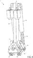
FIG. 4 is another perspective view illustrating the drive mechanism inFIG.1 . -
FIG. 5 is another perspective view illustrating the drive mechanism inFIG.1 . -
FIG. 6 is another perspective view illustrating the drive mechanism inFIG.1 . -
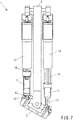
FIG. 7 is another perspective view illustrating the drive mechanism inFIG.1 . -
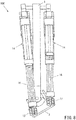
FIG. 8 is a perspective view illustrating a comparative example of the drive mechanism. -
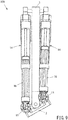
FIG. 9 is another perspective view illustrating the drive mechanism inFIG.8 . - Hereunder, a drive mechanism according to one embodiment of the present invention will be described referring to the drawings. Note that the drive mechanism according to this embodiment is particularly suitable for a drive mechanism in a joint portion (for example, ankle joint) of a humanoid robot.
- Note that the drive mechanism according to the present invention is not limited to application to the joint portion of the humanoid robot and can be broadly applied to a drive mechanism in a driven body requiring operation of at least two degrees of freedom.
- The
drive mechanism 1 according to this embodiment illustrated inFIG. 1 is for realizing the operation of two degrees of freedom in a drivenbody 2. The drivenbody 2 is for example a component of an ankle joint of the humanoid robot, and performs operation of at least two degrees of freedom upon walking. - The
drive mechanism 1 comprises an elongated frame member (base portion) 3 having a center axis A0 in the longitudinal direction. Auniversal joint 4 is provided at a lower end portion of theframe member 3, and a drivenbody 2 is tiltably connected to theframe member 3 by theuniversal joint 4. - The
universal joint 4 has a first rotational axis A1 orthogonal to the center axis A0 and a second rotational axis A2 orthogonal to the first rotational axis A1 and tiltable about the first rotational axis A1. - The
universal joint 4 comprises afirst axis member 5 extending along the first rotational axis A1 and asecond axis member 6 extending along the second rotational axis A2. Thefirst axis member 5 is supported by amounting member 7 provided in front of and behind the lower end portion of theframe member 3. Thesecond axis member 6 is supported by ablock piece 8 provided at the center of thefirst axis member 5. - The driven
body 2 has a pair of left andright flange portions 9, and theflange portions 9 are supported by thesecond axis member 6 of theuniversal joint 4 such that the drivenbody 2 can be rotated about the second rotational axis A2. - As mentioned above, by providing the driven
body 2 at the lower end of theframe member 3 via theuniversal joint 4, the drivenbody 2 can perform a tilt operation about the first rotational axis A1 (roll operation) and the tilt operation about the second rotational axis A2 (pitch operation). - The
drive mechanism 1 according to this embodiment further comprises a pair oflink mechanisms 10 as a power transmission unit for transmitting power to the drivenbody 2. The pair oflink mechanisms 10 are arranged on both sides with respect to a first imaginary plane including the center axis A0 and the first rotational axis A1. Each of the pair oflink mechanisms 10 has afirst link member 11, asecond link member 12, and athird link member 13. - The
first link member 11 has a base end portion provided to the left and right side surfaces of theframe member 3 so as to rotate about a third rotational axis A3 perpendicular to the first imaginary plane. - A
second link member 12 has a base end portion connected to a distal end portion of thefirst link member 11 so as to rotate about the fourth rotational axis A4 parallel to the third rotational axis A3. - A
third link member 13 is provided to theflange portion 9 of the drivenbody 2 so as to rotate about a fifth rotational axis A5 in a second imaginary plane perpendicular to the second rotational axis A2. A distal end portion of thesecond link member 12 is connected to thethird link member 13 so as to rotate about a sixth rotational axis A6 orthogonal to the fifth rotational axis A5. - The distal end portion of the
first link member 11 and the base end portion of thesecond link member 12 are connected by a spherical joint. Further, the distal end portion of thesecond link member 12 and thethird link member 13 are connected by a spherical joint. - A pair of electric cylinders (drive sources) 14 as a power generation unit are provided to the both left and right sides of the
frame member 3 of thedrive mechanism 1 symmetrically with respect to the first imaginary plane. The base end portion of theelectric cylinder 14 is connected to ablock member 15 provided to theframe member 13 so as to rotate about a seventh rotational axis A7 parallel to the second rotational axis A2. - A distal end of each
rod 16 of the pair ofelectric cylinders 14 is connected to the distal end portion of thefirst link member 11 so as to rotate about the fourth rotational axis A4. - Each of the pair of
electric cylinders 14 is provided with aservo motor 17 which can be driven independently from each other. Theelectric cylinder 14 has a ball screw mechanism therein, and power of theservo motor 17 is transmitted to the ball screw mechanism via abelt 18. - In the
drive mechanism 1 illustrated inFIG. 2 to FIG. 7 , the rod of theelectric cylinder 14 is configured by a plurality of elongated members, while the other structure is the same as thedrive mechanism 1 illustrated inFIG. 1 . Note that, inFIG. 3 ,FIG. 5 , andFIG. 6 , part of the cylinder body is cut out so that the internal structure of theelectric cylinder 14 can be seen. - As illustrated in
FIG. 3 ,FIG. 5 , andFIG. 6 , in thedrive mechanism 1 according to this embodiment, ascrew shaft 19 of theelectric cylinder 14 is rotationally driven so that anut 20 screwed to thescrew shaft 19 is driven forward and backward along thescrew shaft 19. Note that a base end portion of therod 16 is connected to thenut 20, and therod 16 is driven forward and backward integrally with thenut 20. - Thus, by the configuration that the
screw shaft 19 is rotationally driven to drive thenut 20 forward and backward, various merits as described below will be obtained, comparing to the configuration that the nut is rotationally driven to drive the screw shaft forward and backward. - First, the mechanical efficiency is increased, compared to the case that the nut is rotationally driven to drive the screw shaft forward and backward. Secondly, a structure to be driven can be formed more easily compared to the case when the nut is rotationally driven to drive the screw shaft forward and backward. Thirdly, when the nut is rotationally driven, the screw shaft goes in and out via the nut forward and backward, thus a dead space is formed and the space factor is deteriorated.
- As illustrated in
FIG. 1 andFIG. 2 toFIG. 7 , by changing the extension/contraction amount of therods 16 of the left and rightelectric cylinders 14 independently from each other, the roll operation and pitch operation can be performed in the drivenbody 2. - As described above, in the
drive mechanism 1 according to this embodiment, power of the pair ofelectric cylinders 14 mounted to theframe member 3 is transmitted to the drivenbody 2 via the pair oflink mechanisms 10 without using a planetary gear speed increasing mechanism. Therefore, it is possible to secure a desired operation angle range in the drivenbody 2 without causing a large deflection as in the case of using the planetary gear speed increasing mechanism. - Additionally, in the
drive mechanism 1, the distance between the third rotational axis A3 and the fourth rotational axis A4 is set to be longer than the distance between the second rotational axis A2 and the sixth rotational axis A6 when it is parallel to the second rotational axis A2. Thereby, it is possible to secure a speed increasing ratio when driving therod 16 of theelectric cylinder 14 so as to be extended/contracted to cause the drivenbody 2 to perform the tilt operation. As a result, the stroke required in theelectric cylinder 14 becomes shorter and theelectric cylinder 14 can be shortened. -
FIG. 8 andFIG. 9 illustrate adrive mechanism 100 as a comparative example. In this example, thefirst link member 11 and thesecond link member 12 are omitted and therod 16 of theelectric cylinder 14 is directly connected to thethird link member 13. Note that, inFIG. 8 andFIG. 9 , part of the cylinder body is cut out so that the internal structure of theelectric cylinder 14 can be seen. - As seen from the
FIG. 8 andFIG. 9 , in thisdrive mechanism 100 as a comparative example, when therod 16 of theelectric cylinder 14 is extended/contracted for performing the tilt operation (roll operation and pitch operation) in the drivenbody 2, the entireelectric cylinder 14 swings in the lateral direction accordingly. - Therefore, components of the robot cannot be arranged in the range of the swing operation in the lateral direction of the
electric cylinder 14, and it is difficult to arrange members for increasing strength of the robot and cover members for covering the internal structure, for example. - In contrast, in the
drive mechanism 1 according to this embodiment, even when therod 16 of theelectric cylinder 14 is extended/contracted for performing the tilt operation (roll operation and pitch operation) in the drivenbody 2, theelectric cylinder 14 does not swing in the lateral direction and swings only in a direction parallel to the first imaginary plane including the center axis A0 of theframe member 3 and the first rotational axis A1, as illustrated inFIG. 1 to FIG. 7 . - Accordingly, the degree of freedom of arrangement of members for increasing the strength of the robot and cover members for covering the internal structure is significantly improved. Additionally, the
electric cylinder 14 can be shortened as described above, thereby enhancing the degree of freedom of arrangement of the robot's components. - Note that, ball bearings are provided at the both ends of
second link member 12 for expanding the tiltable range of the drivenbody 2 in the above-described embodiment, while the ball bearing may be provided at only one end of thesecond link member 12. - Additionally, although the
electric cylinder 14 driven by theservo motor 17 is used as a drive source in the above-described embodiment, the drive source (power generating unit) in the drive mechanism according to the present invention is not limited to this and any drive source may be employed as long as it can control the rotation angle of thefirst link member 11 about the third rotational axis A3. -
- 1
- drive mechanism
- 2
- driven body
- 3
- frame member (base portion)
- 4
- universal joint
- 5
- first axis member
- 6
- second axis member
- 7
- mounting member
- 8
- block piece
- 9
- flange portion
- 10
- link mechanism (power transmission unit)
- 11
- first link member
- 12
- second link member
- 13
- third link member
- 14
- electric cylinder
- 15
- block member
- 16
- rod of electric cylinder
- 17
- servo motor
- 18
- belt
- 19
- screw shaft of electric cylinder
- 20
- nut of electric cylinder
- A0
- center axis of base portion
- A1
- first rotational axis
- A2
- second rotational axis
- A3
- third rotational axis
- A4
- forth rotational axis
- A5
- fifth rotational axis
- A6
- sixth rotational axis
- A7
- seventh rotational axis
Claims (8)
- A drive mechanism for transmitting power to a driven body so as to drive the driven body at an operation of two degrees of freedom, comprising:a base portion having a center axis;a universal joint for tiltably connecting the driven body to the base portion; anda power transmission unit for transmitting the power to the driven body,wherein the universal joint has a first rotational axis orthogonal to the center axis and a second rotational axis orthogonal to the first rotational axis and tiltable about the first rotational axis,wherein the driven body is provided to the universal joint so as to be rotated about the second rotational axis,wherein the power transmission unit has a pair of link mechanisms which are arranged on both sides with respect to a first imaginary plane including the center axis and the first rotational axis, andwherein each of the pair of link mechanisms has a first link member having a base end portion provided to the base portion so as to be rotated about a third rotational axis perpendicular to the first imaginary plane, a second link member having a base end portion connected to a distal end portion of the first link member so as to be rotated about a fourth rotational axis parallel to the third rotational axis, and a third link member which is provided to the driven body so as to be rotated about a fifth rotational axis in a second imaginary plane perpendicular to the second rotational axis and to which a distal end portion of the second link member is provided so as to be rotated about a sixth rotational axis orthogonal to the fifth rotational axis.
- The drive mechanism according to claim 1,
wherein the distal end portion of the first link member and the base end portion of the second link member are connected by a spherical joint. - The drive mechanism according to claim 1 or 2,
wherein the distal end portion of the second link member and the third link member are connected by a spherical joint. - The drive mechanism according to any one of claims 1 to 3, further comprising a power generation unit for generating the power,
wherein the power generation unit has a pair of drive sources which are arranged on both sides with respect to the first imaginary plane. - The drive mechanism according to claim 4,
wherein the pair of drive sources has a pair of cylinders, and
wherein a distal end of each rod of the pair of cylinders is connected to the first link member. - The drive mechanism according to claim 5,
wherein the pair of cylinders are provided to the base portion so as to be rotated about a seventh rotational axis perpendicular to the first imaginary plane. - The drive mechanism according to claim 5 or 6,
wherein the cylinder is an electric cylinder having a screw shaft and a nut screwed to the screw shaft, and
wherein the power generation unit is configured such that the screw shaft is rotationally driven thereby driving the nut forward and backward to generate the power. - The drive mechanism according to any one of claims 1 to 7,
wherein a distance between the third rotational axis and the fourth rotational axis is different from a distance between the second rotational axis and the sixth rotational axis when the sixth rotational axis is parallel to the second rotational axis.
Applications Claiming Priority (2)
| Application Number | Priority Date | Filing Date | Title |
|---|---|---|---|
| JP2015236635 | 2015-12-03 | ||
| PCT/JP2016/086123 WO2017094922A1 (en) | 2015-12-03 | 2016-12-05 | Two-degree-of-freedom drive mechanism |
Publications (3)
| Publication Number | Publication Date |
|---|---|
| EP3385571A1 true EP3385571A1 (en) | 2018-10-10 |
| EP3385571A4 EP3385571A4 (en) | 2019-08-07 |
| EP3385571B1 EP3385571B1 (en) | 2024-03-13 |
Family
ID=58797400
Family Applications (1)
| Application Number | Title | Priority Date | Filing Date |
|---|---|---|---|
| EP16870856.8A Active EP3385571B1 (en) | 2015-12-03 | 2016-12-05 | Two-degree-of-freedom drive mechanism |
Country Status (7)
| Country | Link |
|---|---|
| US (1) | US10828787B2 (en) |
| EP (1) | EP3385571B1 (en) |
| JP (1) | JP6803338B2 (en) |
| KR (2) | KR102458112B1 (en) |
| CN (3) | CN122040828A (en) |
| ES (1) | ES2978184T3 (en) |
| WO (1) | WO2017094922A1 (en) |
Cited By (3)
| Publication number | Priority date | Publication date | Assignee | Title |
|---|---|---|---|---|
| WO2020123833A1 (en) * | 2018-12-14 | 2020-06-18 | Moog Inc. | Humanoid lower body robot electro hydrostatic actuating ankle |
| WO2021162851A1 (en) * | 2020-02-13 | 2021-08-19 | Boston Dynamics, Inc. | Non-planar linear actuator |
| EP4026669A4 (en) * | 2019-09-02 | 2023-11-01 | Kawasaki Jukogyo Kabushiki Kaisha | SPHERICAL JOINT AND ROBOT JOINT STRUCTURE INCLUDING SAME |
Families Citing this family (17)
| Publication number | Priority date | Publication date | Assignee | Title |
|---|---|---|---|---|
| EP3450115B1 (en) * | 2016-06-08 | 2021-03-31 | Nintendo Co., Ltd. | Passive walking device and passive walking module |
| JP6799445B2 (en) * | 2016-11-24 | 2020-12-16 | 川崎重工業株式会社 | Robot joint structure |
| US10814478B2 (en) * | 2017-12-15 | 2020-10-27 | National Cheng Kung University | Joint module and multi-joint modular robot arm |
| CN111867522B (en) | 2018-03-13 | 2024-04-05 | 深圳健行仿生技术有限公司 | Auxiliary device and control method thereof |
| US12103160B2 (en) * | 2018-04-25 | 2024-10-01 | Mitsubishi Electric Corporation | Rotation connecting mechanism, robot, robot arm, and robot hand |
| WO2020031772A1 (en) * | 2018-08-08 | 2020-02-13 | ソニー株式会社 | Link structure |
| KR102748174B1 (en) * | 2018-12-12 | 2024-12-31 | 삼성전자주식회사 | Link assembly and motion assist apparatus comprising the same |
| JP7149208B2 (en) * | 2019-03-14 | 2022-10-06 | 川崎重工業株式会社 | robot joint structure |
| CN110082501B (en) * | 2019-04-29 | 2021-05-28 | 中南大学 | Geological Core Spatial Attitude Restoration Device |
| US20210331310A1 (en) * | 2020-04-28 | 2021-10-28 | Ubtech Robotics Corp Ltd | Neck mechanism for robot |
| CN111730583A (en) * | 2020-06-28 | 2020-10-02 | 中国科学院苏州生物医学工程技术研究所 | Two-degree-of-freedom asymmetric parallel rotating mechanism |
| CN113558928B (en) * | 2021-06-21 | 2023-12-22 | 浙江工业大学 | An ankle joint motion rehabilitation robot |
| WO2023287393A1 (en) * | 2021-07-12 | 2023-01-19 | Google Llc | Robot appendage actuation |
| JP2024094898A (en) * | 2022-12-28 | 2024-07-10 | 川崎重工業株式会社 | Robot joint structure and robot |
| CN116673991A (en) * | 2023-04-14 | 2023-09-01 | 上海清宝引擎机器人有限公司 | Parallel double-degree-of-freedom simulation robot wrist structure |
| CN121180326A (en) * | 2024-06-14 | 2025-12-23 | 北京有竹居网络技术有限公司 | Robot limb structure and robots |
| KR102908120B1 (en) * | 2024-09-25 | 2026-01-07 | 감기백 | Walking robot for painting and its control method |
Family Cites Families (11)
| Publication number | Priority date | Publication date | Assignee | Title |
|---|---|---|---|---|
| JP4255663B2 (en) * | 2002-08-28 | 2009-04-15 | 本田技研工業株式会社 | Legged mobile robot |
| KR100541433B1 (en) * | 2002-12-23 | 2006-01-11 | 삼성전자주식회사 | 2-footed walking robot |
| JP4299583B2 (en) * | 2003-05-20 | 2009-07-22 | 本田技研工業株式会社 | Legged mobile robot |
| WO2006025446A1 (en) * | 2004-09-01 | 2006-03-09 | Matsushita Electric Industrial Co., Ltd. | Joint driving device |
| JP4589712B2 (en) | 2004-12-14 | 2010-12-01 | 本田技研工業株式会社 | Robot joint structure |
| CN100588512C (en) | 2006-02-01 | 2010-02-10 | 本田技研工业株式会社 | Automatic mechanical joint structure |
| JP5602057B2 (en) | 2010-03-29 | 2014-10-08 | 本田技研工業株式会社 | Legged mobile robot and swing structure |
| JP5468973B2 (en) * | 2010-04-22 | 2014-04-09 | 本田技研工業株式会社 | Legged mobile robot |
| CN101934525B (en) * | 2010-09-15 | 2012-07-25 | 北京航空航天大学 | Variable-rigidity flexible joint design of humanoid robot |
| JP5722747B2 (en) * | 2011-10-24 | 2015-05-27 | Thk株式会社 | Robot joint structure and robot incorporating this joint structure |
| CN104308262B (en) * | 2014-10-11 | 2017-04-19 | 浙江创龙机器人制造有限公司 | Manipulator device for disc saw blade |
-
2016
- 2016-12-05 CN CN202610262638.5A patent/CN122040828A/en active Pending
- 2016-12-05 WO PCT/JP2016/086123 patent/WO2017094922A1/en not_active Ceased
- 2016-12-05 KR KR1020217029181A patent/KR102458112B1/en active Active
- 2016-12-05 CN CN201680070544.2A patent/CN108291618A/en active Pending
- 2016-12-05 KR KR1020187018680A patent/KR20180088448A/en not_active Ceased
- 2016-12-05 CN CN202511715348.3A patent/CN121649973A/en active Pending
- 2016-12-05 US US15/781,465 patent/US10828787B2/en active Active
- 2016-12-05 EP EP16870856.8A patent/EP3385571B1/en active Active
- 2016-12-05 JP JP2017554218A patent/JP6803338B2/en active Active
- 2016-12-05 ES ES16870856T patent/ES2978184T3/en active Active
Cited By (6)
| Publication number | Priority date | Publication date | Assignee | Title |
|---|---|---|---|---|
| WO2020123833A1 (en) * | 2018-12-14 | 2020-06-18 | Moog Inc. | Humanoid lower body robot electro hydrostatic actuating ankle |
| EP4026669A4 (en) * | 2019-09-02 | 2023-11-01 | Kawasaki Jukogyo Kabushiki Kaisha | SPHERICAL JOINT AND ROBOT JOINT STRUCTURE INCLUDING SAME |
| US12343863B2 (en) | 2019-09-02 | 2025-07-01 | Kawasaki Jukogyo Kabushiki Kaisha | Spherical joint and joint structure for robot having the same |
| WO2021162851A1 (en) * | 2020-02-13 | 2021-08-19 | Boston Dynamics, Inc. | Non-planar linear actuator |
| US11752645B2 (en) | 2020-02-13 | 2023-09-12 | Boston Dynamics, Inc. | Non-planar linear actuator |
| US12122044B2 (en) | 2020-02-13 | 2024-10-22 | Boston Dynamics, Inc. | Non-planar linear actuator |
Also Published As
| Publication number | Publication date |
|---|---|
| CN121649973A (en) | 2026-03-13 |
| KR20210116692A (en) | 2021-09-27 |
| WO2017094922A1 (en) | 2017-06-08 |
| US20190168400A1 (en) | 2019-06-06 |
| CN122040828A (en) | 2026-05-15 |
| US10828787B2 (en) | 2020-11-10 |
| ES2978184T3 (en) | 2024-09-06 |
| JP6803338B2 (en) | 2020-12-23 |
| CN108291618A (en) | 2018-07-17 |
| EP3385571A4 (en) | 2019-08-07 |
| JPWO2017094922A1 (en) | 2018-09-20 |
| KR20180088448A (en) | 2018-08-03 |
| KR102458112B1 (en) | 2022-10-24 |
| EP3385571B1 (en) | 2024-03-13 |
Similar Documents
| Publication | Publication Date | Title |
|---|---|---|
| US10828787B2 (en) | Drive mechanism of two degrees of freedom | |
| US20210197909A1 (en) | Leg mechanism and humanoid robot | |
| KR102010612B1 (en) | Parallel link robot | |
| TWI573657B (en) | A parallel-kinematical machine with gimbal holders | |
| JP2012240158A (en) | Rotational wave motion mechanism | |
| US9897148B2 (en) | Reducer of electric power-assisted steering apparatus | |
| CN105666471B (en) | A kind of SPS+UPU+ (2RPS+R) type four-freedom-degree parallel-connection robot | |
| US10378639B2 (en) | Reducer of electric power steering apparatus | |
| US20160089776A1 (en) | Compact Parallel Kinematics Robot | |
| US11014251B2 (en) | Joint structure for robot | |
| WO2019109330A1 (en) | Robot of scara type and method for manufacturing the robot | |
| JP2014061571A (en) | Universal joint and parallel link robot having the same | |
| CN1678434A (en) | walking mobile robot | |
| WO2016133105A1 (en) | Industrial robot | |
| US11130245B2 (en) | Parallel integrated drive mechanism | |
| CN110524518B (en) | Two-shift one-rotation less-branch-chain redundant drive fully-symmetrical parallel mechanism | |
| CN102240911A (en) | Incompletely-symmetrical four-freedom-degree space in-parallel mechanism with two-dimensional rotation and two-dimensional movement | |
| US11338453B2 (en) | Joint structure for robot | |
| CN219969848U (en) | Lower limb components of bipedal robots | |
| CN106974461B (en) | Multi freedom VR seat drive arrangement and VR seat | |
| KR20230008856A (en) | steering column device | |
| KR102196484B1 (en) | Joint actuating control module for robot | |
| US11040442B2 (en) | Robot | |
| RU154785U1 (en) | SPATIAL MECHANISM | |
| WO2020115247A1 (en) | A movement simulator |
Legal Events
| Date | Code | Title | Description |
|---|---|---|---|
| STAA | Information on the status of an ep patent application or granted ep patent |
Free format text: STATUS: THE INTERNATIONAL PUBLICATION HAS BEEN MADE |
|
| PUAI | Public reference made under article 153(3) epc to a published international application that has entered the european phase |
Free format text: ORIGINAL CODE: 0009012 |
|
| STAA | Information on the status of an ep patent application or granted ep patent |
Free format text: STATUS: REQUEST FOR EXAMINATION WAS MADE |
|
| 17P | Request for examination filed |
Effective date: 20180621 |
|
| AK | Designated contracting states |
Kind code of ref document: A1 Designated state(s): AL AT BE BG CH CY CZ DE DK EE ES FI FR GB GR HR HU IE IS IT LI LT LU LV MC MK MT NL NO PL PT RO RS SE SI SK SM TR |
|
| AX | Request for extension of the european patent |
Extension state: BA ME |
|
| DAV | Request for validation of the european patent (deleted) | ||
| DAX | Request for extension of the european patent (deleted) | ||
| A4 | Supplementary search report drawn up and despatched |
Effective date: 20190708 |
|
| RIC1 | Information provided on ipc code assigned before grant |
Ipc: F16H 21/02 20060101AFI20190702BHEP Ipc: B25J 9/12 20060101ALI20190702BHEP Ipc: B25J 9/10 20060101ALI20190702BHEP Ipc: B62D 57/032 20060101ALN20190702BHEP Ipc: F16H 21/46 20060101ALI20190702BHEP Ipc: F16C 11/06 20060101ALI20190702BHEP Ipc: B25J 17/02 20060101ALI20190702BHEP Ipc: B25J 17/00 20060101ALI20190702BHEP |
|
| STAA | Information on the status of an ep patent application or granted ep patent |
Free format text: STATUS: EXAMINATION IS IN PROGRESS |
|
| 17Q | First examination report despatched |
Effective date: 20221005 |
|
| GRAP | Despatch of communication of intention to grant a patent |
Free format text: ORIGINAL CODE: EPIDOSNIGR1 |
|
| STAA | Information on the status of an ep patent application or granted ep patent |
Free format text: STATUS: GRANT OF PATENT IS INTENDED |
|
| RIC1 | Information provided on ipc code assigned before grant |
Ipc: B62D 57/032 20060101ALN20230915BHEP Ipc: B25J 17/02 20060101ALI20230915BHEP Ipc: F16C 11/06 20060101ALI20230915BHEP Ipc: B25J 9/12 20060101ALI20230915BHEP Ipc: B25J 9/10 20060101ALI20230915BHEP Ipc: F16H 21/46 20060101ALI20230915BHEP Ipc: B25J 17/00 20060101ALI20230915BHEP Ipc: F16H 21/02 20060101AFI20230915BHEP |
|
| INTG | Intention to grant announced |
Effective date: 20231002 |
|
| GRAS | Grant fee paid |
Free format text: ORIGINAL CODE: EPIDOSNIGR3 |
|
| GRAA | (expected) grant |
Free format text: ORIGINAL CODE: 0009210 |
|
| STAA | Information on the status of an ep patent application or granted ep patent |
Free format text: STATUS: THE PATENT HAS BEEN GRANTED |
|
| AK | Designated contracting states |
Kind code of ref document: B1 Designated state(s): AL AT BE BG CH CY CZ DE DK EE ES FI FR GB GR HR HU IE IS IT LI LT LU LV MC MK MT NL NO PL PT RO RS SE SI SK SM TR |
|
| REG | Reference to a national code |
Ref country code: GB Ref legal event code: FG4D |
|
| REG | Reference to a national code |
Ref country code: CH Ref legal event code: EP |
|
| REG | Reference to a national code |
Ref country code: DE Ref legal event code: R096 Ref document number: 602016086340 Country of ref document: DE |
|
| REG | Reference to a national code |
Ref country code: IE Ref legal event code: FG4D |
|
| PG25 | Lapsed in a contracting state [announced via postgrant information from national office to epo] |
Ref country code: LT Free format text: LAPSE BECAUSE OF FAILURE TO SUBMIT A TRANSLATION OF THE DESCRIPTION OR TO PAY THE FEE WITHIN THE PRESCRIBED TIME-LIMIT Effective date: 20240313 |
|
| REG | Reference to a national code |
Ref country code: LT Ref legal event code: MG9D |
|
| PG25 | Lapsed in a contracting state [announced via postgrant information from national office to epo] |
Ref country code: GR Free format text: LAPSE BECAUSE OF FAILURE TO SUBMIT A TRANSLATION OF THE DESCRIPTION OR TO PAY THE FEE WITHIN THE PRESCRIBED TIME-LIMIT Effective date: 20240614 |
|
| REG | Reference to a national code |
Ref country code: NL Ref legal event code: MP Effective date: 20240313 |
|
| PG25 | Lapsed in a contracting state [announced via postgrant information from national office to epo] |
Ref country code: RS Free format text: LAPSE BECAUSE OF FAILURE TO SUBMIT A TRANSLATION OF THE DESCRIPTION OR TO PAY THE FEE WITHIN THE PRESCRIBED TIME-LIMIT Effective date: 20240613 Ref country code: HR Free format text: LAPSE BECAUSE OF FAILURE TO SUBMIT A TRANSLATION OF THE DESCRIPTION OR TO PAY THE FEE WITHIN THE PRESCRIBED TIME-LIMIT Effective date: 20240313 |
|
| PG25 | Lapsed in a contracting state [announced via postgrant information from national office to epo] |
Ref country code: RS Free format text: LAPSE BECAUSE OF FAILURE TO SUBMIT A TRANSLATION OF THE DESCRIPTION OR TO PAY THE FEE WITHIN THE PRESCRIBED TIME-LIMIT Effective date: 20240613 Ref country code: NO Free format text: LAPSE BECAUSE OF FAILURE TO SUBMIT A TRANSLATION OF THE DESCRIPTION OR TO PAY THE FEE WITHIN THE PRESCRIBED TIME-LIMIT Effective date: 20240613 Ref country code: LT Free format text: LAPSE BECAUSE OF FAILURE TO SUBMIT A TRANSLATION OF THE DESCRIPTION OR TO PAY THE FEE WITHIN THE PRESCRIBED TIME-LIMIT Effective date: 20240313 Ref country code: HR Free format text: LAPSE BECAUSE OF FAILURE TO SUBMIT A TRANSLATION OF THE DESCRIPTION OR TO PAY THE FEE WITHIN THE PRESCRIBED TIME-LIMIT Effective date: 20240313 Ref country code: GR Free format text: LAPSE BECAUSE OF FAILURE TO SUBMIT A TRANSLATION OF THE DESCRIPTION OR TO PAY THE FEE WITHIN THE PRESCRIBED TIME-LIMIT Effective date: 20240614 Ref country code: FI Free format text: LAPSE BECAUSE OF FAILURE TO SUBMIT A TRANSLATION OF THE DESCRIPTION OR TO PAY THE FEE WITHIN THE PRESCRIBED TIME-LIMIT Effective date: 20240313 Ref country code: BG Free format text: LAPSE BECAUSE OF FAILURE TO SUBMIT A TRANSLATION OF THE DESCRIPTION OR TO PAY THE FEE WITHIN THE PRESCRIBED TIME-LIMIT Effective date: 20240313 |
|
| REG | Reference to a national code |
Ref country code: AT Ref legal event code: MK05 Ref document number: 1666023 Country of ref document: AT Kind code of ref document: T Effective date: 20240313 |
|
| PG25 | Lapsed in a contracting state [announced via postgrant information from national office to epo] |
Ref country code: SE Free format text: LAPSE BECAUSE OF FAILURE TO SUBMIT A TRANSLATION OF THE DESCRIPTION OR TO PAY THE FEE WITHIN THE PRESCRIBED TIME-LIMIT Effective date: 20240313 Ref country code: LV Free format text: LAPSE BECAUSE OF FAILURE TO SUBMIT A TRANSLATION OF THE DESCRIPTION OR TO PAY THE FEE WITHIN THE PRESCRIBED TIME-LIMIT Effective date: 20240313 |
|
| PG25 | Lapsed in a contracting state [announced via postgrant information from national office to epo] |
Ref country code: NL Free format text: LAPSE BECAUSE OF FAILURE TO SUBMIT A TRANSLATION OF THE DESCRIPTION OR TO PAY THE FEE WITHIN THE PRESCRIBED TIME-LIMIT Effective date: 20240313 |
|
| REG | Reference to a national code |
Ref country code: ES Ref legal event code: FG2A Ref document number: 2978184 Country of ref document: ES Kind code of ref document: T3 Effective date: 20240906 |
|
| PG25 | Lapsed in a contracting state [announced via postgrant information from national office to epo] |
Ref country code: NL Free format text: LAPSE BECAUSE OF FAILURE TO SUBMIT A TRANSLATION OF THE DESCRIPTION OR TO PAY THE FEE WITHIN THE PRESCRIBED TIME-LIMIT Effective date: 20240313 |
|
| PG25 | Lapsed in a contracting state [announced via postgrant information from national office to epo] |
Ref country code: IS Free format text: LAPSE BECAUSE OF FAILURE TO SUBMIT A TRANSLATION OF THE DESCRIPTION OR TO PAY THE FEE WITHIN THE PRESCRIBED TIME-LIMIT Effective date: 20240713 |
|
| PG25 | Lapsed in a contracting state [announced via postgrant information from national office to epo] |
Ref country code: SM Free format text: LAPSE BECAUSE OF FAILURE TO SUBMIT A TRANSLATION OF THE DESCRIPTION OR TO PAY THE FEE WITHIN THE PRESCRIBED TIME-LIMIT Effective date: 20240313 Ref country code: PT Free format text: LAPSE BECAUSE OF FAILURE TO SUBMIT A TRANSLATION OF THE DESCRIPTION OR TO PAY THE FEE WITHIN THE PRESCRIBED TIME-LIMIT Effective date: 20240715 |
|
| PG25 | Lapsed in a contracting state [announced via postgrant information from national office to epo] |
Ref country code: CZ Free format text: LAPSE BECAUSE OF FAILURE TO SUBMIT A TRANSLATION OF THE DESCRIPTION OR TO PAY THE FEE WITHIN THE PRESCRIBED TIME-LIMIT Effective date: 20240313 Ref country code: EE Free format text: LAPSE BECAUSE OF FAILURE TO SUBMIT A TRANSLATION OF THE DESCRIPTION OR TO PAY THE FEE WITHIN THE PRESCRIBED TIME-LIMIT Effective date: 20240313 |
|
| PG25 | Lapsed in a contracting state [announced via postgrant information from national office to epo] |
Ref country code: AT Free format text: LAPSE BECAUSE OF FAILURE TO SUBMIT A TRANSLATION OF THE DESCRIPTION OR TO PAY THE FEE WITHIN THE PRESCRIBED TIME-LIMIT Effective date: 20240313 |
|
| PG25 | Lapsed in a contracting state [announced via postgrant information from national office to epo] |
Ref country code: PL Free format text: LAPSE BECAUSE OF FAILURE TO SUBMIT A TRANSLATION OF THE DESCRIPTION OR TO PAY THE FEE WITHIN THE PRESCRIBED TIME-LIMIT Effective date: 20240313 |
|
| PG25 | Lapsed in a contracting state [announced via postgrant information from national office to epo] |
Ref country code: SK Free format text: LAPSE BECAUSE OF FAILURE TO SUBMIT A TRANSLATION OF THE DESCRIPTION OR TO PAY THE FEE WITHIN THE PRESCRIBED TIME-LIMIT Effective date: 20240313 |
|
| PG25 | Lapsed in a contracting state [announced via postgrant information from national office to epo] |
Ref country code: SM Free format text: LAPSE BECAUSE OF FAILURE TO SUBMIT A TRANSLATION OF THE DESCRIPTION OR TO PAY THE FEE WITHIN THE PRESCRIBED TIME-LIMIT Effective date: 20240313 Ref country code: SK Free format text: LAPSE BECAUSE OF FAILURE TO SUBMIT A TRANSLATION OF THE DESCRIPTION OR TO PAY THE FEE WITHIN THE PRESCRIBED TIME-LIMIT Effective date: 20240313 Ref country code: RO Free format text: LAPSE BECAUSE OF FAILURE TO SUBMIT A TRANSLATION OF THE DESCRIPTION OR TO PAY THE FEE WITHIN THE PRESCRIBED TIME-LIMIT Effective date: 20240313 Ref country code: PT Free format text: LAPSE BECAUSE OF FAILURE TO SUBMIT A TRANSLATION OF THE DESCRIPTION OR TO PAY THE FEE WITHIN THE PRESCRIBED TIME-LIMIT Effective date: 20240715 Ref country code: PL Free format text: LAPSE BECAUSE OF FAILURE TO SUBMIT A TRANSLATION OF THE DESCRIPTION OR TO PAY THE FEE WITHIN THE PRESCRIBED TIME-LIMIT Effective date: 20240313 Ref country code: IS Free format text: LAPSE BECAUSE OF FAILURE TO SUBMIT A TRANSLATION OF THE DESCRIPTION OR TO PAY THE FEE WITHIN THE PRESCRIBED TIME-LIMIT Effective date: 20240713 Ref country code: EE Free format text: LAPSE BECAUSE OF FAILURE TO SUBMIT A TRANSLATION OF THE DESCRIPTION OR TO PAY THE FEE WITHIN THE PRESCRIBED TIME-LIMIT Effective date: 20240313 Ref country code: CZ Free format text: LAPSE BECAUSE OF FAILURE TO SUBMIT A TRANSLATION OF THE DESCRIPTION OR TO PAY THE FEE WITHIN THE PRESCRIBED TIME-LIMIT Effective date: 20240313 Ref country code: AT Free format text: LAPSE BECAUSE OF FAILURE TO SUBMIT A TRANSLATION OF THE DESCRIPTION OR TO PAY THE FEE WITHIN THE PRESCRIBED TIME-LIMIT Effective date: 20240313 |
|
| REG | Reference to a national code |
Ref country code: DE Ref legal event code: R097 Ref document number: 602016086340 Country of ref document: DE |
|
| PG25 | Lapsed in a contracting state [announced via postgrant information from national office to epo] |
Ref country code: DK Free format text: LAPSE BECAUSE OF FAILURE TO SUBMIT A TRANSLATION OF THE DESCRIPTION OR TO PAY THE FEE WITHIN THE PRESCRIBED TIME-LIMIT Effective date: 20240313 |
|
| PLBE | No opposition filed within time limit |
Free format text: ORIGINAL CODE: 0009261 |
|
| STAA | Information on the status of an ep patent application or granted ep patent |
Free format text: STATUS: NO OPPOSITION FILED WITHIN TIME LIMIT |
|
| PG25 | Lapsed in a contracting state [announced via postgrant information from national office to epo] |
Ref country code: DK Free format text: LAPSE BECAUSE OF FAILURE TO SUBMIT A TRANSLATION OF THE DESCRIPTION OR TO PAY THE FEE WITHIN THE PRESCRIBED TIME-LIMIT Effective date: 20240313 |
|
| 26N | No opposition filed |
Effective date: 20241216 |
|
| PG25 | Lapsed in a contracting state [announced via postgrant information from national office to epo] |
Ref country code: SI Free format text: LAPSE BECAUSE OF FAILURE TO SUBMIT A TRANSLATION OF THE DESCRIPTION OR TO PAY THE FEE WITHIN THE PRESCRIBED TIME-LIMIT Effective date: 20240313 |
|
| PG25 | Lapsed in a contracting state [announced via postgrant information from national office to epo] |
Ref country code: MC Free format text: LAPSE BECAUSE OF FAILURE TO SUBMIT A TRANSLATION OF THE DESCRIPTION OR TO PAY THE FEE WITHIN THE PRESCRIBED TIME-LIMIT Effective date: 20240313 |
|
| REG | Reference to a national code |
Ref country code: CH Ref legal event code: PL |
|
| PG25 | Lapsed in a contracting state [announced via postgrant information from national office to epo] |
Ref country code: LU Free format text: LAPSE BECAUSE OF NON-PAYMENT OF DUE FEES Effective date: 20241205 |
|
| GBPC | Gb: european patent ceased through non-payment of renewal fee |
Effective date: 20241205 |
|
| REG | Reference to a national code |
Ref country code: BE Ref legal event code: MM Effective date: 20241231 |
|
| PG25 | Lapsed in a contracting state [announced via postgrant information from national office to epo] |
Ref country code: GB Free format text: LAPSE BECAUSE OF NON-PAYMENT OF DUE FEES Effective date: 20241205 Ref country code: BE Free format text: LAPSE BECAUSE OF NON-PAYMENT OF DUE FEES Effective date: 20241231 |
|
| PG25 | Lapsed in a contracting state [announced via postgrant information from national office to epo] |
Ref country code: CH Free format text: LAPSE BECAUSE OF NON-PAYMENT OF DUE FEES Effective date: 20241231 |
|
| PG25 | Lapsed in a contracting state [announced via postgrant information from national office to epo] |
Ref country code: IE Free format text: LAPSE BECAUSE OF NON-PAYMENT OF DUE FEES Effective date: 20241205 |
|
| PGFP | Annual fee paid to national office [announced via postgrant information from national office to epo] |
Ref country code: DE Payment date: 20251028 Year of fee payment: 10 |
|
| PGFP | Annual fee paid to national office [announced via postgrant information from national office to epo] |
Ref country code: IT Payment date: 20251121 Year of fee payment: 10 |
|
| PGFP | Annual fee paid to national office [announced via postgrant information from national office to epo] |
Ref country code: FR Payment date: 20251110 Year of fee payment: 10 |
|
| PG25 | Lapsed in a contracting state [announced via postgrant information from national office to epo] |
Ref country code: CY Free format text: LAPSE BECAUSE OF FAILURE TO SUBMIT A TRANSLATION OF THE DESCRIPTION OR TO PAY THE FEE WITHIN THE PRESCRIBED TIME-LIMIT; INVALID AB INITIO Effective date: 20161205 |
|
| PGFP | Annual fee paid to national office [announced via postgrant information from national office to epo] |
Ref country code: ES Payment date: 20260108 Year of fee payment: 10 |
|
| PG25 | Lapsed in a contracting state [announced via postgrant information from national office to epo] |
Ref country code: TR Free format text: LAPSE BECAUSE OF FAILURE TO SUBMIT A TRANSLATION OF THE DESCRIPTION OR TO PAY THE FEE WITHIN THE PRESCRIBED TIME-LIMIT Effective date: 20240313 |
|
| PG25 | Lapsed in a contracting state [announced via postgrant information from national office to epo] |
Ref country code: HU Free format text: LAPSE BECAUSE OF FAILURE TO SUBMIT A TRANSLATION OF THE DESCRIPTION OR TO PAY THE FEE WITHIN THE PRESCRIBED TIME-LIMIT; INVALID AB INITIO Effective date: 20161205 |