EP3385503A1 - Particle removal device for gas turbine and gas turbine including the same - Google Patents
Particle removal device for gas turbine and gas turbine including the same Download PDFInfo
- Publication number
- EP3385503A1 EP3385503A1 EP17206875.1A EP17206875A EP3385503A1 EP 3385503 A1 EP3385503 A1 EP 3385503A1 EP 17206875 A EP17206875 A EP 17206875A EP 3385503 A1 EP3385503 A1 EP 3385503A1
- Authority
- EP
- European Patent Office
- Prior art keywords
- gas turbine
- flow path
- vane
- particle
- compressed air
- Prior art date
- Legal status (The legal status is an assumption and is not a legal conclusion. Google has not performed a legal analysis and makes no representation as to the accuracy of the status listed.)
- Granted
Links
Images



Classifications
-
- F—MECHANICAL ENGINEERING; LIGHTING; HEATING; WEAPONS; BLASTING
- F02—COMBUSTION ENGINES; HOT-GAS OR COMBUSTION-PRODUCT ENGINE PLANTS
- F02C—GAS-TURBINE PLANTS; AIR INTAKES FOR JET-PROPULSION PLANTS; CONTROLLING FUEL SUPPLY IN AIR-BREATHING JET-PROPULSION PLANTS
- F02C7/00—Features, components parts, details or accessories, not provided for in, or of interest apart form groups F02C1/00 - F02C6/00; Air intakes for jet-propulsion plants
- F02C7/04—Air intakes for gas-turbine plants or jet-propulsion plants
- F02C7/05—Air intakes for gas-turbine plants or jet-propulsion plants having provisions for obviating the penetration of damaging objects or particles
-
- F—MECHANICAL ENGINEERING; LIGHTING; HEATING; WEAPONS; BLASTING
- F02—COMBUSTION ENGINES; HOT-GAS OR COMBUSTION-PRODUCT ENGINE PLANTS
- F02C—GAS-TURBINE PLANTS; AIR INTAKES FOR JET-PROPULSION PLANTS; CONTROLLING FUEL SUPPLY IN AIR-BREATHING JET-PROPULSION PLANTS
- F02C7/00—Features, components parts, details or accessories, not provided for in, or of interest apart form groups F02C1/00 - F02C6/00; Air intakes for jet-propulsion plants
- F02C7/04—Air intakes for gas-turbine plants or jet-propulsion plants
- F02C7/05—Air intakes for gas-turbine plants or jet-propulsion plants having provisions for obviating the penetration of damaging objects or particles
- F02C7/052—Air intakes for gas-turbine plants or jet-propulsion plants having provisions for obviating the penetration of damaging objects or particles with dust-separation devices
-
- F—MECHANICAL ENGINEERING; LIGHTING; HEATING; WEAPONS; BLASTING
- F01—MACHINES OR ENGINES IN GENERAL; ENGINE PLANTS IN GENERAL; STEAM ENGINES
- F01D—NON-POSITIVE DISPLACEMENT MACHINES OR ENGINES, e.g. STEAM TURBINES
- F01D5/00—Blades; Blade-carrying members; Heating, heat-insulating, cooling or antivibration means on the blades or the members
- F01D5/02—Blade-carrying members, e.g. rotors
- F01D5/08—Heating, heat-insulating or cooling means
- F01D5/081—Cooling fluid being directed on the side of the rotor disc or at the roots of the blades
-
- B—PERFORMING OPERATIONS; TRANSPORTING
- B01—PHYSICAL OR CHEMICAL PROCESSES OR APPARATUS IN GENERAL
- B01D—SEPARATION
- B01D45/00—Separating dispersed particles from gases or vapours by gravity, inertia, or centrifugal forces
- B01D45/12—Separating dispersed particles from gases or vapours by gravity, inertia, or centrifugal forces by centrifugal forces
- B01D45/16—Separating dispersed particles from gases or vapours by gravity, inertia, or centrifugal forces by centrifugal forces generated by the winding course of the gas stream, the centrifugal forces being generated solely or partly by mechanical means, e.g. fixed swirl vanes
-
- F—MECHANICAL ENGINEERING; LIGHTING; HEATING; WEAPONS; BLASTING
- F01—MACHINES OR ENGINES IN GENERAL; ENGINE PLANTS IN GENERAL; STEAM ENGINES
- F01D—NON-POSITIVE DISPLACEMENT MACHINES OR ENGINES, e.g. STEAM TURBINES
- F01D25/00—Component parts, details, or accessories, not provided for in, or of interest apart from, other groups
- F01D25/08—Cooling; Heating; Heat-insulation
- F01D25/12—Cooling
-
- F—MECHANICAL ENGINEERING; LIGHTING; HEATING; WEAPONS; BLASTING
- F01—MACHINES OR ENGINES IN GENERAL; ENGINE PLANTS IN GENERAL; STEAM ENGINES
- F01D—NON-POSITIVE DISPLACEMENT MACHINES OR ENGINES, e.g. STEAM TURBINES
- F01D9/00—Stators
- F01D9/02—Nozzles; Nozzle boxes; Stator blades; Guide conduits, e.g. individual nozzles
-
- F—MECHANICAL ENGINEERING; LIGHTING; HEATING; WEAPONS; BLASTING
- F02—COMBUSTION ENGINES; HOT-GAS OR COMBUSTION-PRODUCT ENGINE PLANTS
- F02C—GAS-TURBINE PLANTS; AIR INTAKES FOR JET-PROPULSION PLANTS; CONTROLLING FUEL SUPPLY IN AIR-BREATHING JET-PROPULSION PLANTS
- F02C7/00—Features, components parts, details or accessories, not provided for in, or of interest apart form groups F02C1/00 - F02C6/00; Air intakes for jet-propulsion plants
- F02C7/12—Cooling of plants
- F02C7/16—Cooling of plants characterised by cooling medium
- F02C7/18—Cooling of plants characterised by cooling medium the medium being gaseous, e.g. air
-
- F—MECHANICAL ENGINEERING; LIGHTING; HEATING; WEAPONS; BLASTING
- F02—COMBUSTION ENGINES; HOT-GAS OR COMBUSTION-PRODUCT ENGINE PLANTS
- F02C—GAS-TURBINE PLANTS; AIR INTAKES FOR JET-PROPULSION PLANTS; CONTROLLING FUEL SUPPLY IN AIR-BREATHING JET-PROPULSION PLANTS
- F02C9/00—Controlling gas-turbine plants; Controlling fuel supply in air- breathing jet-propulsion plants
- F02C9/16—Control of working fluid flow
- F02C9/18—Control of working fluid flow by bleeding, bypassing or acting on variable working fluid interconnections between turbines or compressors or their stages
-
- F—MECHANICAL ENGINEERING; LIGHTING; HEATING; WEAPONS; BLASTING
- F04—POSITIVE - DISPLACEMENT MACHINES FOR LIQUIDS; PUMPS FOR LIQUIDS OR ELASTIC FLUIDS
- F04D—NON-POSITIVE-DISPLACEMENT PUMPS
- F04D29/00—Details, component parts, or accessories
- F04D29/40—Casings; Connections of working fluid
- F04D29/52—Casings; Connections of working fluid for axial pumps
- F04D29/54—Fluid-guiding means, e.g. diffusers
- F04D29/541—Specially adapted for elastic fluid pumps
- F04D29/542—Bladed diffusers
-
- F—MECHANICAL ENGINEERING; LIGHTING; HEATING; WEAPONS; BLASTING
- F02—COMBUSTION ENGINES; HOT-GAS OR COMBUSTION-PRODUCT ENGINE PLANTS
- F02C—GAS-TURBINE PLANTS; AIR INTAKES FOR JET-PROPULSION PLANTS; CONTROLLING FUEL SUPPLY IN AIR-BREATHING JET-PROPULSION PLANTS
- F02C3/00—Gas-turbine plants characterised by the use of combustion products as the working fluid
- F02C3/04—Gas-turbine plants characterised by the use of combustion products as the working fluid having a turbine driving a compressor
-
- F—MECHANICAL ENGINEERING; LIGHTING; HEATING; WEAPONS; BLASTING
- F05—INDEXING SCHEMES RELATING TO ENGINES OR PUMPS IN VARIOUS SUBCLASSES OF CLASSES F01-F04
- F05D—INDEXING SCHEME FOR ASPECTS RELATING TO NON-POSITIVE-DISPLACEMENT MACHINES OR ENGINES, GAS-TURBINES OR JET-PROPULSION PLANTS
- F05D2220/00—Application
- F05D2220/30—Application in turbines
- F05D2220/32—Application in turbines in gas turbines
-
- F—MECHANICAL ENGINEERING; LIGHTING; HEATING; WEAPONS; BLASTING
- F05—INDEXING SCHEMES RELATING TO ENGINES OR PUMPS IN VARIOUS SUBCLASSES OF CLASSES F01-F04
- F05D—INDEXING SCHEME FOR ASPECTS RELATING TO NON-POSITIVE-DISPLACEMENT MACHINES OR ENGINES, GAS-TURBINES OR JET-PROPULSION PLANTS
- F05D2220/00—Application
- F05D2220/30—Application in turbines
- F05D2220/32—Application in turbines in gas turbines
- F05D2220/321—Application in turbines in gas turbines for a special turbine stage
- F05D2220/3212—Application in turbines in gas turbines for a special turbine stage the first stage of a turbine
-
- F—MECHANICAL ENGINEERING; LIGHTING; HEATING; WEAPONS; BLASTING
- F05—INDEXING SCHEMES RELATING TO ENGINES OR PUMPS IN VARIOUS SUBCLASSES OF CLASSES F01-F04
- F05D—INDEXING SCHEME FOR ASPECTS RELATING TO NON-POSITIVE-DISPLACEMENT MACHINES OR ENGINES, GAS-TURBINES OR JET-PROPULSION PLANTS
- F05D2240/00—Components
- F05D2240/10—Stators
- F05D2240/12—Fluid guiding means, e.g. vanes
-
- F—MECHANICAL ENGINEERING; LIGHTING; HEATING; WEAPONS; BLASTING
- F05—INDEXING SCHEMES RELATING TO ENGINES OR PUMPS IN VARIOUS SUBCLASSES OF CLASSES F01-F04
- F05D—INDEXING SCHEME FOR ASPECTS RELATING TO NON-POSITIVE-DISPLACEMENT MACHINES OR ENGINES, GAS-TURBINES OR JET-PROPULSION PLANTS
- F05D2240/00—Components
- F05D2240/35—Combustors or associated equipment
-
- F—MECHANICAL ENGINEERING; LIGHTING; HEATING; WEAPONS; BLASTING
- F05—INDEXING SCHEMES RELATING TO ENGINES OR PUMPS IN VARIOUS SUBCLASSES OF CLASSES F01-F04
- F05D—INDEXING SCHEME FOR ASPECTS RELATING TO NON-POSITIVE-DISPLACEMENT MACHINES OR ENGINES, GAS-TURBINES OR JET-PROPULSION PLANTS
- F05D2260/00—Function
- F05D2260/60—Fluid transfer
- F05D2260/607—Preventing clogging or obstruction of flow paths by dirt, dust, or foreign particles
-
- Y—GENERAL TAGGING OF NEW TECHNOLOGICAL DEVELOPMENTS; GENERAL TAGGING OF CROSS-SECTIONAL TECHNOLOGIES SPANNING OVER SEVERAL SECTIONS OF THE IPC; TECHNICAL SUBJECTS COVERED BY FORMER USPC CROSS-REFERENCE ART COLLECTIONS [XRACs] AND DIGESTS
- Y02—TECHNOLOGIES OR APPLICATIONS FOR MITIGATION OR ADAPTATION AGAINST CLIMATE CHANGE
- Y02T—CLIMATE CHANGE MITIGATION TECHNOLOGIES RELATED TO TRANSPORTATION
- Y02T50/00—Aeronautics or air transport
- Y02T50/60—Efficient propulsion technologies, e.g. for aircraft
Definitions
- the present invention relates to a particle removal device for a gas turbine and a gas turbine including the same.
- a gas turbine includes a compressor, a combustor and a turbine.
- the compressor compresses external air introduced from the outside and transfers the compressed air to the combustor.
- the air compressed in the compressor becomes high-pressure and high-temperature air.
- the combustor mixes the compressed air, introduced from the compressor, with fuel, and combusts the mixed air.
- the combusted gas resulting from the combustion is discharged to the turbine.
- the turbine is rotated by the combusted gas, thereby generating power.
- the generated power is used in various fields such as for the generation of electricity and to drive machinery.
- the gas turbine is a power engine, which is configured to mix air, compressed in a compressor, with fuel, combust the mixed air, and rotate a turbine using the high temperature generated by the combustion.
- the gas turbine is used to drive a generator, an aircraft, a locomotive and the like.
- Some of the compressed air discharged from the compressor is supplied to a combustor, and the remaining compressed air is supplied to a first vane close to the combustor so as to cool the first vane.
- the compressed air supplied to the first vane contains various kinds of particles, such as dust and foreign substances, there is a problem whereby a flow path is clogged due to the particles such as dust.
- the present invention has been made in view of the above problems, and it is an object of the present invention to provide a particle removal device for a gas turbine and a gas turbine including the same, which are able to collect and remove particles, such as foreign substances, contained in compressed air supplied to a first vane, thereby preventing clogging of a flow path.
- a particle removal device for a gas turbine including a suction inlet formed in one side of a region below a first vane so as to introduce compressed air discharged from a compressor, combusted gas generated in a combustor flowing through the first vane, an acceleration flow path for accelerating the compressed air introduced through the suction inlet so as to separate particles from the compressed air by centrifugal force, a particle collector provided at one end of the acceleration flow path so as to collect the separated particles, and a particle discharger communicating with the particle collector so as to discharge the collected particles to an outside.
- the acceleration flow path may include an inclined surface adapted not only to enable compressed air, which is introduced in a direction parallel to an axial direction of the gas turbine, to be introduced into the first vane in a direction perpendicular to the axial direction of the gas turbine but also to accelerate the compressed air.
- the particle collector may be formed in a first support member supporting a platform of the first vane, and the first support member may be provided at an end of the acceleration flow path and may have a size larger than the width of a lower end of the platform of the first vane.
- the particle discharger may be formed in a lower portion of the first support member so as to have a pipe shape.
- the particle removal device may further include a first guide member projecting from a second support member supporting a platform of the first vane, in a downward direction or in a direction perpendicular to an inclined surface of the acceleration flow path.
- the particle removal device may further include a second guide member projecting from a side surface of a first support member supporting a platform of the first vane, in a horizontal direction.
- the particle removal device may further include a third guide member projecting from a side end of the acceleration flow path in a horizontal direction.
- the particle removal device may further include a subsidiary particle collector formed in a portion of an inclined surface of the acceleration flow path.
- the subsidiary particle collector may include a connecting passage communicating with the particle collector.
- the particle removal device may further include a first guide member, projecting from a second support member supporting a platform of the first vane in a downward direction or in a direction perpendicular to an inclined surface of the acceleration flow path, a second guide member, projecting from a side surface of a first support member supporting the platform of the first vane in a horizontal direction, a third guide member projecting from a side end of the acceleration flow path in a horizontal direction, and a subsidiary particle collector formed in a portion of the inclined surface of the acceleration flow path.
- a gas turbine including a compressor for compressing air, a combustor for mixing compressed air, introduced from the compressor, with fuel, a turbine adapted to be rotated by the combusted gas supplied from the combustor so as to generate power, and a particle removal device including a suction inlet formed in one side of a region below a first vane so as to introduce compressed air discharged from a compressor, combusted gas generated in a combustor flowing through the first vane, an acceleration flow path for accelerating the compressed air introduced through the suction inlet so as to separate particles from the compressed air by centrifugal force, a particle collector provided at one end of the acceleration flow path so as to collect the separated particles, and a particle discharger communicating with the particle collector so as to discharge the collected particles to an outside.
- the acceleration flow path may include an inclined surface adapted not only to enable compressed air, which is introduced in a direction parallel to an axial direction of the gas turbine, to be introduced into the first vane in a direction perpendicular to the axial direction of the gas turbine but also to accelerate the compressed air.
- the particle collector may be formed in a first support member supporting a platform of the first vane, and the first support member may be provided at an end of the acceleration flow path and may have a size larger than the width of a lower end of the platform of the first vane.
- the particle discharger may be formed in a lower portion of the first support member so as to have a pipe shape.
- the gas turbine may further include a first guide member projecting from a second support member supporting a platform of the first vane, in a downward direction or in a direction perpendicular to an inclined surface of the acceleration flow path.
- the gas turbine may further include a second guide member projecting from a side surface of a first support member supporting a platform of the first vane, in a horizontal direction.
- the gas turbine may further include a third guide member projecting from a side end of the acceleration flow path in a horizontal direction.
- the gas turbine may further include a subsidiary particle collector formed in a portion of an inclined surface of the acceleration flow path.
- the subsidiary particle collector may include a connecting passage communicating with the particle collector.
- the gas turbine may further include a first guide member, projecting from a second support member supporting a platform of the first vane in a downward direction or in a direction perpendicular to an inclined surface of the acceleration flow path, a second guide member, projecting from a side surface of a first support member supporting the platform of the first vane in a horizontal direction, a third guide member, projecting from a side end of the acceleration flow path in a horizontal direction, and a subsidiary particle collector formed in a portion of the inclined surface of the acceleration flow path.
- FIG. 1 is a view illustrating the internal structure of a gas turbine according to an embodiment of the present invention
- FIG. 2 is a view illustrating a combustor of the gas turbine.
- the gas turbine 1000 includes a compressor 1100, a combustor 1200 and a turbine 1300.
- the compressor 1100 includes a plurality of blades 1110, which are arranged in a radial fashion.
- the compressor 1100 rotates the plurality of blades 1110, and air is thus moved while being compressed due to the rotation of the blades 1110.
- the size and mounting angle of the blades 1110 may be varied depending on the mounting position.
- the compressor 1100 may be directly or indirectly connected to the turbine 1300 so as to receive some of the power generated by the turbine 1300, which is in turn used to rotate the blades 1110.
- the air compressed in the compressor 1100 is moved to the combustor 1200.
- the combustor 1200 includes a plurality of combustion chambers 1210 and a plurality of fuel nozzle modules 1220, which are arranged in a circular pattern.
- Each of the plurality of combustion chambers 1210 includes a sleeve 1211, a combustion liner 1212, a fuel nozzle base 1213 and a combustion zone 1214.
- the sleeve 1211 defines the external wall of the combustion chamber 1210, and extends in one direction.
- the sleeve 1211 may be configured to have a cylindrical shape.
- the combustion liner 1212 is spaced apart from the sleeve 1211 by a predetermined distance such that an annular flow space 1215 is defined between the sleeve 1211 and the combustion liner 1212.
- the fuel nozzle base 1213 is fitted into the end of the sleeve 1211 so as to hermetically seal the sleeve 1211.
- the fuel nozzle base 1213 may be coupled to a manifold for supplying fuel to fuel nozzles 1221, the associated valves and the like.
- the combustion zone 1214 is the space, in which combustion actually occurs, and is defined by part of the combustion liner 1212.
- the fuel nozzle module 1220 is mounted in the combustion chamber 1210.
- the fuel nozzle module 1220 includes a plurality of fuel nozzle assemblies. The number of fuel nozzle assemblies may be varied depending on the capacity of the gas turbine 1000.
- Each of the plurality of fuel nozzle assemblies includes a fuel nozzle 1221 and a shroud 1222.
- a single combustion chamber 1210 may be provided therein with a plurality of fuel nozzle assemblies. Fuel required for combustion is injected through the fuel nozzles 1221.
- the fuel nozzle 1221 is supported at one end thereof by the fuel nozzle base 1213.
- the shroud 1222 is configured to surround the fuel nozzle 1221 in a state of being spaced apart from the fuel nozzle 1221.
- the shroud 1222 may be configured to have a pipe shape, preferably a circular pipe shape.
- the fuel nozzle 1221 may be provided with a swirling vane (not shown), which is inwardly located at a predetermined distance from the inlet of the shroud 1222.
- the combustion liner 1212 is provided at the rear end thereof with a transition piece 1217 for supplying combusted gas to the turbine 1300.
- the transition piece 1217 may be provided with a flow path for the acceleration of gas.
- a plurality of transition pieces 1217 may be arranged in a circular pattern at the connection region of the turbine 1300.
- the air compressed in the compressor 1100 is introduced through cooling holes 1216 formed in the sleeve 1211, and flows along the flowing space 1215 while cooling the combustion liner 1212.
- the compressed air which flows along the flowing space 1215, reaches the fuel nozzle base 1213 positioned at the end of the sleeve 1211.
- the compressed air is turned in direction at the fuel nozzle base 1213, and is introduced into the inlet of the shroud 1222 of the fuel nozzle assembly 1220.
- the compressed air, which is introduced into the shroud 1222 is moved to the combustion zone 1214 while being mixed with fuel injected through the fuel nozzles 1221.
- the compressed air is ignited in the combustion zone 1214 by means of a spark plug (not shown). Subsequently, the combusted gas is discharged to the turbine 1300 so as to rotate the turbine 1300.
- FIG. 3 is a view illustrating a portion of the turbine according to the embodiment of the present invention
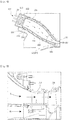
- FIG. 4 is an enlarged view of portion "A" of FIG. 3 , which shows a particle removal device according to a first embodiment of the present invention.
- the turbine 1300 may be constructed such that turbine vanes 1310 and turbine blades 1320 are alternately arranged in the axial direction of the gas turbine.
- Combusted gas HG having a high temperature rotates the turbine blades 1320 while passing through the turbine vanes 1310 and the turbine blades 1320 in the axial direction.
- Some of the compressed air discharged from the compressor 110 is supplied to the turbine vanes 1310 so as to cool the turbine vanes 1310.
- the one among the plurality of turbine vanes that is first cooled by the compressed air discharged from the compressor 1100 is the first vane.
- the present invention proposes the particle removal device, which is provided below the first vane 1310 so as to remove particles contained in the compressed air introduced into the first vane 1310.
- the particle removal device includes a suction inlet 2100, an acceleration flow path 2200, a particle collector 2300 and a particle discharger 2400.
- the suction inlet 210 is formed in the front side of a region below the first vane 1301 (the side close to the compressor), through which the combusted gas generated in the combustor 1200 flows, so as introduce the compressed air discharged from the compressor 1100.
- the shape and the size of the suction inlet 2100 may be varied depending on size and mounting position of the first vane 1310.
- the suction inlet 210 may be composed of a plurality of suction inlets.
- the acceleration flow path 2200 accelerates the compressed air, which is introduced through the suction inlet 2100, so as to separate particles from the compressed air by centrifugal force.
- the acceleration flow path 2200 is configured to be inclined with respect to the axial direction at a predetermined angle. Particles having a relatively large mass, such as dust and foreign substances, flow along a trajectory having a radius larger than that of the compressed air having a relatively low mass while the compressed air introduced through the suction inlet 2100 passes through the acceleration flow path 2200. Consequently, the particles are separated from the compressed air by centrifugal force (inertial force).
- the separated particles are collected in the particle collector 2300 formed in the end of the acceleration flow path 2200.
- the particle collector 2300 may be formed in a first support member 1312 supporting a platform 1311 of the first vane 1310 so as to have a pocket shape.
- the first support member 1312 is provided at the end of the acceleration flow path 2200, and has a width larger than the width of the lower end of the platform 1311 of the first vane 1301.
- the particle collector 2300 may be formed by depressing an upstream region of a lower portion of the first support member 1312. Therefore, the particle collector 2300 may be formed merely changing the shape of the support member 1312, even without providing an existing gas turbine with an additional space.
- the particles, such as dust, collected in the particle collector 2300 are discharged to the outside through the particle discharger 2400.
- the particle discharger 2400 communicates with the particle collector 2300.
- the particle discharger 2400 may be formed in the lower portion of the first support member 1312 so as to have a pipe shape.
- the particle removal device is able to collect and remove particles, such as foreign substances, contained in compressed air supplied to the first vane 1301, thereby preventing the flow path from being clogged.
- FIG. 5 is a view illustrating a particle removal device according to a second embodiment of the present invention.
- the particle removal device according to the second embodiment of the present further includes a first guide member 2500, in addition to the suction inlet 2100, the acceleration flow path 2200, the particle collector 2300 and the particle discharger 2400.
- the first guide member 2500 may be configured to project from a second support member 1313, which supports the platform 1311 of the first vane 1310 in a downward direction or in a direction perpendicular to the inclined surface of the acceleration flow path 2200.
- the first guide member 2500 is able to reduce the cross-sectional area of the acceleration flow path 2200 and thus increase the accelerative force of the compressed air introduced through the suction inlet 2100, thereby improving the ability to separate particles from the compressed air by centrifugal force.
- FIG. 6 is a view illustrating a particle removal device according to a third embodiment of the present invention.
- the particle removal device according to the third embodiment of the present invention further includes a second guide member 2600, in addition to the suction inlet 2100, the acceleration flow path 2200, the particle collector 2300 and the particle discharger 2400.
- the second guide member 2600 may be configured to project in a horizontal direction from the side surface of the first support member 1312 that supports the platform 1311 of the first vane 1310.
- the second guide member 2600 serves to guide fine particles, which have a relatively low mass and are thus subjected to a lower centrifugal force, among the particles contained in the compressed air introduced through the suction inlet 2100, into the particle collector 2300.
- the fine particles, which are subjected to a lower centrifugal force may be collected in the particle collector 2300 due to collision with the second guide member 2600.
- FIG. 7 is a view illustrating a particle removal device according to a fourth embodiment of the present invention.
- the particle removal device according to the fourth embodiment of the present further includes a third guide member 2700, in addition to the suction inlet 2100, the acceleration flow path 2200, the particle collector 2300 and the particle discharger 2400.
- the third guide member 2700 may be configured to project in a horizontal direction from the downstream end of the acceleration flow path 2200.
- the third guide member 2700 is able not only to guide particles collected in the particle collector 2300 such that the particles are easily introduced into the particle discharger 2400 but also to prevent the particles collected in the particle collector 2300 from flowing back.
- FIG. 8 is a view illustrating a particle removal device according to a fifth embodiment of the present invention.
- the particle removal device according to the fifth embodiment of the present invention further includes a subsidiary particle collector 2800, in addition to the suction inlet 2100, the acceleration flow path 2200, the particle collector 2300 and the particle discharger 2400.
- the subsidiary particle collector 2800 is formed by depression of a portion of the inclined surface of the acceleration flow path 2200, and is provided with a connecting passage 2810 communicating with the particle collector 2300.
- the subsidiary particle collector 2800 is able to collect particles that have a relatively high mass and are thus subjected to a high centrifugal force, among the particles contained in the compressed air introduced through the suction inlet 2100.
- the particles which are subjected to a high centrifugal force, come into contact with an upstream surface of the inclined surface of the acceleration flow path 2200, which is close to the compressor.
- the particles, which come into contact with the upstream surface flow into the particle collector 2300 by virtue of the stream of compressed air, there is the concern of the particles adhering to the inclined surface of the acceleration flow path 2200 and of additional particles continuing to accumulate on the adhered particles upon operation for a prolonged period. Consequently, there is the concern that the accumulated particles will not be introduced into the particle collector 2300 but will instead be introduced into the first vane 1310 by the stream of the compressed air.
- the particle removal device includes the subsidiary particle collector 2800, which is provided at the inclined surface of the acceleration flow path 2200, in order to collect particles having a high mass.
- the particles introduced into the subsidiary particle collector 2800 are introduced into the particle collector 2300 through the connecting passage 2810, and are then discharged to the outside through the particle discharger 2400.
- FIG. 9 is a view illustrating a particle removal device according to a sixth embodiment of the present invention.
- the particle removal device according to the sixth embodiment of the present invention includes all of the suction inlet 2100, the acceleration flow path 2200, the particle collector 2300, the particle discharger 2400, the first guide member 2500, the second guide member 2600, the third guide member 2700 and the subsidiary particle collector 2800.
- the first guide member 2500 serves to reduce the cross-sectional area of the acceleration flow path 2200 and thus increase the accelerative force of the compressed air introduced through the suction inlet 2100, thereby improving the ability to separate particles from the compressed air by centrifugal force.
- the second guide member 2600 serves to guide fine particles, which have a relatively low mass and are thus subjected to a lower centrifugal force, among particles contained in the compressed air introduced through the suction inlet 2100, into the particle collector 2300.
- the third guide member 2700 serves not only to guide particles collected in the particle collector 2300 such that the particles are easily introduced into the particles discharger 2400 but also to prevent the particles collected in the particle collector 2300 from flowing back.
- the subsidiary particle collector 2800 serves to collect particles, which have a relatively high mass and are thus subjected to a high centrifugal force, among the particles contained in the compressed air introduced through the suction inlet 2100.
Landscapes
- Engineering & Computer Science (AREA)
- Chemical & Material Sciences (AREA)
- Combustion & Propulsion (AREA)
- Mechanical Engineering (AREA)
- General Engineering & Computer Science (AREA)
- Chemical Kinetics & Catalysis (AREA)
- Physics & Mathematics (AREA)
- Fluid Mechanics (AREA)
- Separating Particles In Gases By Inertia (AREA)
- Structures Of Non-Positive Displacement Pumps (AREA)
- Turbine Rotor Nozzle Sealing (AREA)
Abstract
Description
- The present invention relates to a particle removal device for a gas turbine and a gas turbine including the same.
- Generally, a gas turbine includes a compressor, a combustor and a turbine. The compressor compresses external air introduced from the outside and transfers the compressed air to the combustor. The air compressed in the compressor becomes high-pressure and high-temperature air. The combustor mixes the compressed air, introduced from the compressor, with fuel, and combusts the mixed air. The combusted gas resulting from the combustion is discharged to the turbine. The turbine is rotated by the combusted gas, thereby generating power. The generated power is used in various fields such as for the generation of electricity and to drive machinery.
- The gas turbine is a power engine, which is configured to mix air, compressed in a compressor, with fuel, combust the mixed air, and rotate a turbine using the high temperature generated by the combustion. The gas turbine is used to drive a generator, an aircraft, a locomotive and the like.
- Some of the compressed air discharged from the compressor is supplied to a combustor, and the remaining compressed air is supplied to a first vane close to the combustor so as to cool the first vane. At this point, because the compressed air supplied to the first vane contains various kinds of particles, such as dust and foreign substances, there is a problem whereby a flow path is clogged due to the particles such as dust.
- Korean Patent Registration No.
10-0013120 - Therefore, the present invention has been made in view of the above problems, and it is an object of the present invention to provide a particle removal device for a gas turbine and a gas turbine including the same, which are able to collect and remove particles, such as foreign substances, contained in compressed air supplied to a first vane, thereby preventing clogging of a flow path.
- In accordance with an aspect of the present invention, the above and other objects can be accomplished by the provision of a particle removal device for a gas turbine, including a suction inlet formed in one side of a region below a first vane so as to introduce compressed air discharged from a compressor, combusted gas generated in a combustor flowing through the first vane, an acceleration flow path for accelerating the compressed air introduced through the suction inlet so as to separate particles from the compressed air by centrifugal force, a particle collector provided at one end of the acceleration flow path so as to collect the separated particles, and a particle discharger communicating with the particle collector so as to discharge the collected particles to an outside.
- In an aspect of the present invention, the acceleration flow path may include an inclined surface adapted not only to enable compressed air, which is introduced in a direction parallel to an axial direction of the gas turbine, to be introduced into the first vane in a direction perpendicular to the axial direction of the gas turbine but also to accelerate the compressed air.
- In an aspect of the present invention, the particle collector may be formed in a first support member supporting a platform of the first vane, and the first support member may be provided at an end of the acceleration flow path and may have a size larger than the width of a lower end of the platform of the first vane.
- In an aspect of the present invention, the particle discharger may be formed in a lower portion of the first support member so as to have a pipe shape.
- In an aspect of the present invention, the particle removal device may further include a first guide member projecting from a second support member supporting a platform of the first vane, in a downward direction or in a direction perpendicular to an inclined surface of the acceleration flow path.
- In an aspect of the present invention, the particle removal device may further include a second guide member projecting from a side surface of a first support member supporting a platform of the first vane, in a horizontal direction.
- In an aspect of the present invention, the particle removal device may further include a third guide member projecting from a side end of the acceleration flow path in a horizontal direction.
- In an aspect of the present invention, the particle removal device may further include a subsidiary particle collector formed in a portion of an inclined surface of the acceleration flow path.
- In an aspect of the present invention, the subsidiary particle collector may include a connecting passage communicating with the particle collector.
- In an aspect of the present invention, the particle removal device may further include a first guide member, projecting from a second support member supporting a platform of the first vane in a downward direction or in a direction perpendicular to an inclined surface of the acceleration flow path, a second guide member, projecting from a side surface of a first support member supporting the platform of the first vane in a horizontal direction, a third guide member projecting from a side end of the acceleration flow path in a horizontal direction, and a subsidiary particle collector formed in a portion of the inclined surface of the acceleration flow path.
- In accordance with another aspect of the present invention, the above and other objects can be accomplished by the provision of a gas turbine including a compressor for compressing air, a combustor for mixing compressed air, introduced from the compressor, with fuel, a turbine adapted to be rotated by the combusted gas supplied from the combustor so as to generate power, and a particle removal device including a suction inlet formed in one side of a region below a first vane so as to introduce compressed air discharged from a compressor, combusted gas generated in a combustor flowing through the first vane, an acceleration flow path for accelerating the compressed air introduced through the suction inlet so as to separate particles from the compressed air by centrifugal force, a particle collector provided at one end of the acceleration flow path so as to collect the separated particles, and a particle discharger communicating with the particle collector so as to discharge the collected particles to an outside.
- In an aspect of the present invention, the acceleration flow path may include an inclined surface adapted not only to enable compressed air, which is introduced in a direction parallel to an axial direction of the gas turbine, to be introduced into the first vane in a direction perpendicular to the axial direction of the gas turbine but also to accelerate the compressed air.
- In an aspect of the present invention, the particle collector may be formed in a first support member supporting a platform of the first vane, and the first support member may be provided at an end of the acceleration flow path and may have a size larger than the width of a lower end of the platform of the first vane.
- In an aspect of the present invention, the particle discharger may be formed in a lower portion of the first support member so as to have a pipe shape.
- In an aspect of the present invention, the gas turbine may further include a first guide member projecting from a second support member supporting a platform of the first vane, in a downward direction or in a direction perpendicular to an inclined surface of the acceleration flow path.
- In an aspect of the present invention, the gas turbine may further include a second guide member projecting from a side surface of a first support member supporting a platform of the first vane, in a horizontal direction.
- In an aspect of the present invention, the gas turbine may further include a third guide member projecting from a side end of the acceleration flow path in a horizontal direction.
- In an aspect of the present invention, the gas turbine may further include a subsidiary particle collector formed in a portion of an inclined surface of the acceleration flow path.
- In an aspect of the present invention, the subsidiary particle collector may include a connecting passage communicating with the particle collector.
- In the aspect of the present invention, the gas turbine may further include a first guide member, projecting from a second support member supporting a platform of the first vane in a downward direction or in a direction perpendicular to an inclined surface of the acceleration flow path, a second guide member, projecting from a side surface of a first support member supporting the platform of the first vane in a horizontal direction, a third guide member, projecting from a side end of the acceleration flow path in a horizontal direction, and a subsidiary particle collector formed in a portion of the inclined surface of the acceleration flow path.
- The above and other objects, features and other advantages of the present invention will be more clearly understood from the following detailed description taken in conjunction with the accompanying drawings, in which:
-
FIG. 1 is a view illustrating a gas turbine according to an embodiment of the present invention; -
FIG. 2 is a cross-sectional view illustrating a combustor of the gas turbine; -
FIG. 3 is a view illustrating a portion of a turbine according to the embodiment of the present invention; -
FIG. 4 is an enlarged view of portion "A" ofFIG. 3 , which shows a particle removal device according to a first embodiment of the present invention; -
FIG. 5 is a view illustrating a particle removal device according to a second embodiment of the present invention; -
FIG. 6 is a view illustrating a particle removal device according to a third embodiment of the present invention; -
FIG. 7 is a view illustrating a particle removal device according to a fourth embodiment of the present invention; -
FIG. 8 is a view illustrating a particle removal device according to a fifth embodiment of the present invention; and -
FIG. 9 is a view illustrating a particle removal device according to a sixth embodiment of the present invention. - Since embodiments of the present invention can be variously modified in many different forms, reference will now be made in detail to specific embodiments of the present invention. It is to be understood that the present description is not intended to limit the present invention to those specific embodiment and that the present invention is intended to cover not only the specific embodiments but also various alternatives, modifications, equivalents and other embodiments that may be included within the spirit and scope of the present invention as defined by the appended claims.
- The terminology used herein is for the purpose of describing particular embodiments only and is not intended to be limiting. As used herein, the singular forms "a," "an" and "the" are intended to include the plural forms as well, unless the context clearly indicates otherwise. It will be further understood that the terms "comprise", "include", "have", etc. when used in this specification, specify the presence of stated features, integers, steps, operations, elements, components, and/or combinations thereof, but do not preclude the presence or addition of one or more other features, integers, steps, operations, elements, components, and/or combinations thereof.
- Preferred embodiments of the present invention will be described more fully hereinafter with reference to the accompanying drawings. In the accompanying drawings, it should be noted that the same components are described using the same reference numerals as far as possible. In the following description of the present invention, detailed descriptions of known functions and components incorporated herein will be omitted when the same may make the subject matter of the present invention unclear. For the same reason, some components in the drawings may be exaggerated, omitted or diagrammatically illustrated.
-
FIG. 1 is a view illustrating the internal structure of a gas turbine according to an embodiment of the present invention, andFIG. 2 is a view illustrating a combustor of the gas turbine. - As illustrated in
FIGS. 1 and2 , thegas turbine 1000 according to the embodiment of the present includes acompressor 1100, acombustor 1200 and aturbine 1300. Thecompressor 1100 includes a plurality ofblades 1110, which are arranged in a radial fashion. Thecompressor 1100 rotates the plurality ofblades 1110, and air is thus moved while being compressed due to the rotation of theblades 1110. The size and mounting angle of theblades 1110 may be varied depending on the mounting position. In an embodiment, thecompressor 1100 may be directly or indirectly connected to theturbine 1300 so as to receive some of the power generated by theturbine 1300, which is in turn used to rotate theblades 1110. - The air compressed in the
compressor 1100 is moved to thecombustor 1200. Thecombustor 1200 includes a plurality ofcombustion chambers 1210 and a plurality offuel nozzle modules 1220, which are arranged in a circular pattern. - Each of the plurality of
combustion chambers 1210 includes asleeve 1211, acombustion liner 1212, afuel nozzle base 1213 and acombustion zone 1214. Thesleeve 1211 defines the external wall of thecombustion chamber 1210, and extends in one direction. Thesleeve 1211 may be configured to have a cylindrical shape. Thecombustion liner 1212 is spaced apart from thesleeve 1211 by a predetermined distance such that anannular flow space 1215 is defined between thesleeve 1211 and thecombustion liner 1212. Thefuel nozzle base 1213 is fitted into the end of thesleeve 1211 so as to hermetically seal thesleeve 1211. Thefuel nozzle base 1213 may be coupled to a manifold for supplying fuel tofuel nozzles 1221, the associated valves and the like. Thecombustion zone 1214 is the space, in which combustion actually occurs, and is defined by part of thecombustion liner 1212. - The
fuel nozzle module 1220 is mounted in thecombustion chamber 1210. Thefuel nozzle module 1220 includes a plurality of fuel nozzle assemblies. The number of fuel nozzle assemblies may be varied depending on the capacity of thegas turbine 1000. - Each of the plurality of fuel nozzle assemblies includes a
fuel nozzle 1221 and ashroud 1222. Asingle combustion chamber 1210 may be provided therein with a plurality of fuel nozzle assemblies. Fuel required for combustion is injected through thefuel nozzles 1221. Thefuel nozzle 1221 is supported at one end thereof by thefuel nozzle base 1213. Theshroud 1222 is configured to surround thefuel nozzle 1221 in a state of being spaced apart from thefuel nozzle 1221. Theshroud 1222 may be configured to have a pipe shape, preferably a circular pipe shape. Thefuel nozzle 1221 may be provided with a swirling vane (not shown), which is inwardly located at a predetermined distance from the inlet of theshroud 1222. - The
combustion liner 1212 is provided at the rear end thereof with atransition piece 1217 for supplying combusted gas to theturbine 1300. Thetransition piece 1217 may be provided with a flow path for the acceleration of gas. Like thecombustion liners 1212, a plurality oftransition pieces 1217 may be arranged in a circular pattern at the connection region of theturbine 1300. - The air compressed in the
compressor 1100 is introduced throughcooling holes 1216 formed in thesleeve 1211, and flows along the flowingspace 1215 while cooling thecombustion liner 1212. The compressed air, which flows along the flowingspace 1215, reaches thefuel nozzle base 1213 positioned at the end of thesleeve 1211. The compressed air is turned in direction at thefuel nozzle base 1213, and is introduced into the inlet of theshroud 1222 of thefuel nozzle assembly 1220. The compressed air, which is introduced into theshroud 1222, is moved to thecombustion zone 1214 while being mixed with fuel injected through thefuel nozzles 1221. The compressed air is ignited in thecombustion zone 1214 by means of a spark plug (not shown). Subsequently, the combusted gas is discharged to theturbine 1300 so as to rotate theturbine 1300. -
FIG. 3 is a view illustrating a portion of the turbine according to the embodiment of the present invention, andFIG. 4 is an enlarged view of portion "A" ofFIG. 3 , which shows a particle removal device according to a first embodiment of the present invention. - As illustrated in
FIG. 3 , theturbine 1300 may be constructed such thatturbine vanes 1310 andturbine blades 1320 are alternately arranged in the axial direction of the gas turbine. Combusted gas HG having a high temperature rotates theturbine blades 1320 while passing through theturbine vanes 1310 and theturbine blades 1320 in the axial direction. - Some of the compressed air discharged from the compressor 110 is supplied to the
turbine vanes 1310 so as to cool theturbine vanes 1310. The one among the plurality of turbine vanes that is first cooled by the compressed air discharged from thecompressor 1100 is the first vane. - Although a filter (not shown), which is adapted to remove particles such as dust contained in the compressed air, is disposed in front of the first vane 1301 so as to be close to the compressor, the compressed air passed through the filter still contains fine particles, which may cause the flow path for compressed air defined by the first vane to be clogged. Accordingly, the present invention proposes the particle removal device, which is provided below the
first vane 1310 so as to remove particles contained in the compressed air introduced into thefirst vane 1310. - The particle removal device according to the first embodiment of the present invention includes a
suction inlet 2100, anacceleration flow path 2200, aparticle collector 2300 and aparticle discharger 2400. - The suction inlet 210 is formed in the front side of a region below the first vane 1301 (the side close to the compressor), through which the combusted gas generated in the
combustor 1200 flows, so as introduce the compressed air discharged from thecompressor 1100. The shape and the size of thesuction inlet 2100 may be varied depending on size and mounting position of thefirst vane 1310. In order to improve suction efficiency, the suction inlet 210 may be composed of a plurality of suction inlets. - The
acceleration flow path 2200 accelerates the compressed air, which is introduced through thesuction inlet 2100, so as to separate particles from the compressed air by centrifugal force. In order to accelerate the compressed air while allowing the compressed air, which is introduced in the axial direction, to be introduced into thefirst vane 1310 in a direction perpendicular to the axial direction, theacceleration flow path 2200 is configured to be inclined with respect to the axial direction at a predetermined angle. Particles having a relatively large mass, such as dust and foreign substances, flow along a trajectory having a radius larger than that of the compressed air having a relatively low mass while the compressed air introduced through thesuction inlet 2100 passes through theacceleration flow path 2200. Consequently, the particles are separated from the compressed air by centrifugal force (inertial force). - The separated particles are collected in the
particle collector 2300 formed in the end of theacceleration flow path 2200. Theparticle collector 2300 may be formed in afirst support member 1312 supporting aplatform 1311 of thefirst vane 1310 so as to have a pocket shape. Thefirst support member 1312 is provided at the end of theacceleration flow path 2200, and has a width larger than the width of the lower end of theplatform 1311 of the first vane 1301. Theparticle collector 2300 may be formed by depressing an upstream region of a lower portion of thefirst support member 1312. Therefore, theparticle collector 2300 may be formed merely changing the shape of thesupport member 1312, even without providing an existing gas turbine with an additional space. - The particles, such as dust, collected in the
particle collector 2300 are discharged to the outside through theparticle discharger 2400. Theparticle discharger 2400 communicates with theparticle collector 2300. Theparticle discharger 2400 may be formed in the lower portion of thefirst support member 1312 so as to have a pipe shape. - The particle removal device according to the embodiment of the present invention is able to collect and remove particles, such as foreign substances, contained in compressed air supplied to the first vane 1301, thereby preventing the flow path from being clogged.
- Next, particle removal devices according to second to sixth embodiments of the present invention will be described. In the following description, since the
suction inlet 2100, theacceleration flow path 2200, theparticle collector 2300 and theparticle discharger 2400 are substantially identical to those of the first embodiment, a description thereof is omitted. -
FIG. 5 is a view illustrating a particle removal device according to a second embodiment of the present invention. As illustrated inFIG. 5 , the particle removal device according to the second embodiment of the present further includes afirst guide member 2500, in addition to thesuction inlet 2100, theacceleration flow path 2200, theparticle collector 2300 and theparticle discharger 2400. - The
first guide member 2500 may be configured to project from asecond support member 1313, which supports theplatform 1311 of thefirst vane 1310 in a downward direction or in a direction perpendicular to the inclined surface of theacceleration flow path 2200. Thefirst guide member 2500 is able to reduce the cross-sectional area of theacceleration flow path 2200 and thus increase the accelerative force of the compressed air introduced through thesuction inlet 2100, thereby improving the ability to separate particles from the compressed air by centrifugal force. -
FIG. 6 is a view illustrating a particle removal device according to a third embodiment of the present invention. As illustrated inFIG. 6 , the particle removal device according to the third embodiment of the present invention further includes asecond guide member 2600, in addition to thesuction inlet 2100, theacceleration flow path 2200, theparticle collector 2300 and theparticle discharger 2400. - The
second guide member 2600 may be configured to project in a horizontal direction from the side surface of thefirst support member 1312 that supports theplatform 1311 of thefirst vane 1310. Thesecond guide member 2600 serves to guide fine particles, which have a relatively low mass and are thus subjected to a lower centrifugal force, among the particles contained in the compressed air introduced through thesuction inlet 2100, into theparticle collector 2300. The fine particles, which are subjected to a lower centrifugal force, may be collected in theparticle collector 2300 due to collision with thesecond guide member 2600. -
FIG. 7 is a view illustrating a particle removal device according to a fourth embodiment of the present invention. As illustrated inFIG. 7 , the particle removal device according to the fourth embodiment of the present further includes athird guide member 2700, in addition to thesuction inlet 2100, theacceleration flow path 2200, theparticle collector 2300 and theparticle discharger 2400. - The
third guide member 2700 may be configured to project in a horizontal direction from the downstream end of theacceleration flow path 2200. Thethird guide member 2700 is able not only to guide particles collected in theparticle collector 2300 such that the particles are easily introduced into theparticle discharger 2400 but also to prevent the particles collected in theparticle collector 2300 from flowing back. -
FIG. 8 is a view illustrating a particle removal device according to a fifth embodiment of the present invention. As illustrated inFIG. 8 , the particle removal device according to the fifth embodiment of the present invention further includes asubsidiary particle collector 2800, in addition to thesuction inlet 2100, theacceleration flow path 2200, theparticle collector 2300 and theparticle discharger 2400. - The
subsidiary particle collector 2800 is formed by depression of a portion of the inclined surface of theacceleration flow path 2200, and is provided with a connectingpassage 2810 communicating with theparticle collector 2300. Thesubsidiary particle collector 2800 is able to collect particles that have a relatively high mass and are thus subjected to a high centrifugal force, among the particles contained in the compressed air introduced through thesuction inlet 2100. - The particles, which are subjected to a high centrifugal force, come into contact with an upstream surface of the inclined surface of the
acceleration flow path 2200, which is close to the compressor. Although the particles, which come into contact with the upstream surface, flow into theparticle collector 2300 by virtue of the stream of compressed air, there is the concern of the particles adhering to the inclined surface of theacceleration flow path 2200 and of additional particles continuing to accumulate on the adhered particles upon operation for a prolonged period. Consequently, there is the concern that the accumulated particles will not be introduced into theparticle collector 2300 but will instead be introduced into thefirst vane 1310 by the stream of the compressed air. - In order to prevent such accumulation of particles, the particle removal device according to the fifth embodiment of the present invention includes the
subsidiary particle collector 2800, which is provided at the inclined surface of theacceleration flow path 2200, in order to collect particles having a high mass. The particles introduced into thesubsidiary particle collector 2800 are introduced into theparticle collector 2300 through the connectingpassage 2810, and are then discharged to the outside through theparticle discharger 2400. -
FIG. 9 is a view illustrating a particle removal device according to a sixth embodiment of the present invention. As illustrated inFIG. 9 , the particle removal device according to the sixth embodiment of the present invention includes all of thesuction inlet 2100, theacceleration flow path 2200, theparticle collector 2300, theparticle discharger 2400, thefirst guide member 2500, thesecond guide member 2600, thethird guide member 2700 and thesubsidiary particle collector 2800. - The
first guide member 2500 serves to reduce the cross-sectional area of theacceleration flow path 2200 and thus increase the accelerative force of the compressed air introduced through thesuction inlet 2100, thereby improving the ability to separate particles from the compressed air by centrifugal force. - The
second guide member 2600 serves to guide fine particles, which have a relatively low mass and are thus subjected to a lower centrifugal force, among particles contained in the compressed air introduced through thesuction inlet 2100, into theparticle collector 2300. - The
third guide member 2700 serves not only to guide particles collected in theparticle collector 2300 such that the particles are easily introduced into the particles discharger 2400 but also to prevent the particles collected in theparticle collector 2300 from flowing back. - The
subsidiary particle collector 2800 serves to collect particles, which have a relatively high mass and are thus subjected to a high centrifugal force, among the particles contained in the compressed air introduced through thesuction inlet 2100. - As is apparent from the above description, according to the above embodiments of the present invention, it is possible to collect and remove particles, such as foreign substances, contained in the compressed air supplied to the first vane, thereby preventing clogging of the flow path.
- Although the preferred embodiments of the present invention have been disclosed for illustrative purposes, those skilled in the art will appreciate that various modifications, additions and substitutions are possible, without departing from the scope and spirit of the invention as disclosed in the accompanying claims.
Claims (15)
- A particle removal device for a gas turbine, comprising:a suction inlet formed in one side of a region below a first vane so as to introduce compressed air discharged from a compressor, combusted gas generated in a combustor flowing through the first vane;an acceleration flow path for accelerating the compressed air introduced through the suction inlet so as to separate particles from the compressed air by centrifugal force;a particle collector provided at one end of the acceleration flow path so as to collect the separated particles; anda particle discharger communicating with the particle collector so as to discharge the collected particles to an outside.
- The particle removal device for a gas turbine according to claim 1, wherein the acceleration flow path includes an inclined surface adapted not only to enable compressed air, which is introduced in a direction parallel to an axial direction of the gas turbine, to be introduced into the first vane in a direction perpendicular to the axial direction of the gas turbine but also to accelerate the compressed air.
- The particle removal device for a gas turbine according to claim 1 or claim 2, wherein the particle collector is formed in a first support member supporting a platform of the first vane, and the first support member is provided at an end of the acceleration flow path and has a size larger than a width of a lower end of the platform of the first vane.
- The particle removal device for a gas turbine according to any one of claims 1 to 3, further comprising a first guide member, projecting from a second support member supporting a platform of the first vane in a downward direction or in a direction perpendicular to an inclined surface of the acceleration flow path.
- The particle removal device for a gas turbine according to any one of claims 1 to 4, further comprising a second guide member, projecting from a side surface of a first support member supporting a platform of the first vane in a horizontal direction.
- The particle removal device for a gas turbine according to any one of claims 1 to 5, further comprising a third guide member projecting from a side end of the acceleration flow path in a horizontal direction.
- The particle removal device for a gas turbine according to any one of claims 1 to 6, further comprising a subsidiary particle collector formed in a portion of an inclined surface of the acceleration flow path.
- The particle removal device for a gas turbine according to claim 7, wherein the subsidiary particle collector includes a connecting passage communicating with the particle collector.
- A gas turbine comprising:a compressor for compressing air;a combustor for mixing compressed air, introduced from the compressor, with fuel;a turbine adapted to be rotated by combusted gas supplied from the combustor so as to generate power; anda particle removal device including a suction inlet formed in one side of a region below a first vane so as to introduce compressed air discharged from a compressor, combusted gas generated in a combustor flowing through the first vane, an acceleration flow path for accelerating the compressed air introduced through the suction inlet so as to separate particles from the compressed air by centrifugal force, a particle collector provided at one end of the acceleration flow path so as to collect the separated particles, and a particle discharger communicating with the particle collector so as to discharge the collected particles to an outside.
- The gas turbine according to claim 9, wherein the acceleration flow path includes an inclined surface adapted not only to enable compressed air, which is introduced in a direction parallel to an axial direction of the gas turbine, to be introduced into the first vane in a direction perpendicular to the axial direction of the gas turbine but also to accelerate the compressed air.
- The gas turbine according to claim 9 or claim 10, wherein the particle collector is formed in a first support member supporting a platform of the first vane, and the first support member is provided at an end of the acceleration flow path and has a size larger than a width of a lower end of the platform of the first vane.
- The gas turbine according to any one of claims 9 to 11, further comprising a first guide member projecting from a second support member supporting a platform of the first vane in a downward direction or in a direction perpendicular to an inclined surface of the acceleration flow path.
- The gas turbine according to any one of claims 9 to 12, further comprising a second guide member projecting from a side surface of a first support member supporting a platform of the first vane in a horizontal direction.
- The gas turbine according to any one of claims 9 to 13, further comprising a third guide member projecting from a side end of the acceleration flow path in a horizontal direction.
- The gas turbine according to any one of claims 9 to 14, further comprising a subsidiary particle collector formed in a portion of an inclined surface of the acceleration flow path, and including a connecting passage communicating with the particle collector.
Applications Claiming Priority (1)
| Application Number | Priority Date | Filing Date | Title |
|---|---|---|---|
| KR1020170044983A KR101887806B1 (en) | 2017-04-06 | 2017-04-06 | a particle separator of gas turbine and a gas turbine comprising it |
Publications (2)
| Publication Number | Publication Date |
|---|---|
| EP3385503A1 true EP3385503A1 (en) | 2018-10-10 |
| EP3385503B1 EP3385503B1 (en) | 2019-08-28 |
Family
ID=60673486
Family Applications (1)
| Application Number | Title | Priority Date | Filing Date |
|---|---|---|---|
| EP17206875.1A Active EP3385503B1 (en) | 2017-04-06 | 2017-12-13 | Gas turbine including a particle removal device |
Country Status (4)
| Country | Link |
|---|---|
| US (1) | US10774743B2 (en) |
| EP (1) | EP3385503B1 (en) |
| JP (1) | JP6483793B2 (en) |
| KR (1) | KR101887806B1 (en) |
Families Citing this family (4)
| Publication number | Priority date | Publication date | Assignee | Title |
|---|---|---|---|---|
| KR101887806B1 (en) * | 2017-04-06 | 2018-08-10 | 두산중공업 주식회사 | a particle separator of gas turbine and a gas turbine comprising it |
| US10724437B2 (en) * | 2017-06-28 | 2020-07-28 | General Electric Company | Systems and methods for particle separator in a gas turbine engine |
| US11473464B2 (en) * | 2019-08-15 | 2022-10-18 | Pratt & Whitney Canada Corp. | Removal of contaminants from air for use in aircraft engines |
| CN116045312B (en) * | 2023-02-28 | 2025-02-28 | 保定市玄云涡喷动力设备研发有限公司 | Combustion chamber of a micro turbojet engine |
Citations (4)
| Publication number | Priority date | Publication date | Assignee | Title |
|---|---|---|---|---|
| US20080310951A1 (en) * | 2007-06-18 | 2008-12-18 | Honeywell International, Inc. | Turbine cooling air centrifugal particle separator |
| US20110247347A1 (en) * | 2010-04-12 | 2011-10-13 | Todd Ebert | Particle separator in a gas turbine engine |
| WO2014149353A1 (en) * | 2013-03-15 | 2014-09-25 | General Electric Company | Cyclonic dirt separating turbine accelerator |
| KR101647261B1 (en) * | 2015-10-05 | 2016-08-09 | 두산중공업 주식회사 | Debris removal device of a gas turbine |
Family Cites Families (18)
| Publication number | Priority date | Publication date | Assignee | Title |
|---|---|---|---|---|
| KR820001469B1 (en) | 1978-01-21 | 1982-08-21 | 찰스 에이치. 위버 | Combustion apparatus for a gas turbine |
| US4820123A (en) * | 1988-04-25 | 1989-04-11 | United Technologies Corporation | Dirt removal means for air cooled blades |
| DE68906594T2 (en) * | 1988-04-25 | 1993-08-26 | United Technologies Corp | DUST SEPARATOR FOR AN AIR COOLED SHOVEL. |
| KR960016461U (en) | 1994-11-29 | 1996-06-17 | Dust trap device | |
| JP3160484B2 (en) | 1994-12-22 | 2001-04-25 | 三菱重工業株式会社 | Gas turbine blade cooling system |
| US6134874A (en) | 1998-06-02 | 2000-10-24 | Pratt & Whitney Canada Corp. | Integral inertial particle separator for radial inlet gas turbine engine |
| US6413044B1 (en) * | 2000-06-30 | 2002-07-02 | Alstom Power N.V. | Blade cooling in gas turbine |
| US6499285B1 (en) | 2001-08-01 | 2002-12-31 | Rolls-Royce Corporation | Particle separator for a gas turbine engine |
| DE10330471A1 (en) * | 2003-07-05 | 2005-02-03 | Alstom Technology Ltd | Device for separating foreign particles from the cooling air that can be fed to the moving blades of a turbine |
| SE527104C2 (en) * | 2004-05-21 | 2005-12-20 | Alstom Technology Ltd | Method and apparatus for separating dust particles |
| GB0524735D0 (en) * | 2005-12-03 | 2006-01-11 | Rolls Royce Plc | Turbine blade |
| US8262356B2 (en) * | 2009-01-30 | 2012-09-11 | General Electric Company | Rotor chamber cover member having aperture for dirt separation and related turbine |
| US8677766B2 (en) * | 2010-04-12 | 2014-03-25 | Siemens Energy, Inc. | Radial pre-swirl assembly and cooling fluid metering structure for a gas turbine engine |
| JP5917329B2 (en) * | 2012-08-02 | 2016-05-11 | 株式会社東芝 | Steam turbine seal structure |
| US20140119903A1 (en) | 2012-10-29 | 2014-05-01 | United Technologies Corporation | Gas Turbine Engine With Inlet Particle Separator and Thermal Management |
| US9915176B2 (en) * | 2014-05-29 | 2018-03-13 | General Electric Company | Shroud assembly for turbine engine |
| US10450960B2 (en) * | 2015-09-21 | 2019-10-22 | United Technologies Corporation | Tangential on-board injectors for gas turbine engines |
| KR101887806B1 (en) * | 2017-04-06 | 2018-08-10 | 두산중공업 주식회사 | a particle separator of gas turbine and a gas turbine comprising it |
-
2017
- 2017-04-06 KR KR1020170044983A patent/KR101887806B1/en active Active
- 2017-12-07 JP JP2017234937A patent/JP6483793B2/en active Active
- 2017-12-13 EP EP17206875.1A patent/EP3385503B1/en active Active
- 2017-12-14 US US15/842,514 patent/US10774743B2/en active Active
Patent Citations (4)
| Publication number | Priority date | Publication date | Assignee | Title |
|---|---|---|---|---|
| US20080310951A1 (en) * | 2007-06-18 | 2008-12-18 | Honeywell International, Inc. | Turbine cooling air centrifugal particle separator |
| US20110247347A1 (en) * | 2010-04-12 | 2011-10-13 | Todd Ebert | Particle separator in a gas turbine engine |
| WO2014149353A1 (en) * | 2013-03-15 | 2014-09-25 | General Electric Company | Cyclonic dirt separating turbine accelerator |
| KR101647261B1 (en) * | 2015-10-05 | 2016-08-09 | 두산중공업 주식회사 | Debris removal device of a gas turbine |
Also Published As
| Publication number | Publication date |
|---|---|
| KR101887806B1 (en) | 2018-08-10 |
| US10774743B2 (en) | 2020-09-15 |
| JP2018178991A (en) | 2018-11-15 |
| US20180291809A1 (en) | 2018-10-11 |
| EP3385503B1 (en) | 2019-08-28 |
| JP6483793B2 (en) | 2019-03-13 |
Similar Documents
| Publication | Publication Date | Title |
|---|---|---|
| US10450951B2 (en) | Cyclonic separator for a turbine engine | |
| EP3385503B1 (en) | Gas turbine including a particle removal device | |
| CA2671718C (en) | Particle separator and separating method for gas turbine engine | |
| US10167725B2 (en) | Engine component for a turbine engine | |
| US7500364B2 (en) | System for coupling flow from a centrifugal compressor to an axial combustor for gas turbines | |
| EP3225818B1 (en) | Turbine engine designs for improved fine particle separation efficiency | |
| RU2715129C1 (en) | Swirler, combustion chamber unit and gas turbine with improved fuel/air mixing | |
| JP5638301B2 (en) | System and method for a gas turbine combustor | |
| EP1818511A2 (en) | Leaned deswirl vanes behind a centrifugal compressor in a gas turbine engine | |
| US11199111B2 (en) | Assembly for particle removal | |
| CN106988886A (en) | Inlet particle separators for turbogenerator | |
| US20090304502A1 (en) | Pre-diffuser for centrifugal compressor | |
| JP2002242699A (en) | Gas turbine engine with foreign matter removal structure | |
| EP1847779A2 (en) | Optimized configuration of a reverse flow combustion system for a gas turbine engine | |
| US10400670B2 (en) | Inlet particle separator for a turbine engine | |
| US10724437B2 (en) | Systems and methods for particle separator in a gas turbine engine | |
| JP2017166810A (en) | Fuel-air multistage injector in a gas turbine combustion system | |
| EP2806217A2 (en) | Gas turbine engines with fuel injector assemblies | |
| US10393021B2 (en) | Particle separator | |
| US10794402B2 (en) | Ejector and a turbo-machine having an ejector | |
| CN107850308A (en) | Combustor for a gas | |
| CN103134080A (en) | Swirler assembly with compressor discharge injection to vane surface | |
| RU2520785C1 (en) | Gas turbine stage with opening to tap dust concentrate from cooling system |
Legal Events
| Date | Code | Title | Description |
|---|---|---|---|
| PUAI | Public reference made under article 153(3) epc to a published international application that has entered the european phase |
Free format text: ORIGINAL CODE: 0009012 |
|
| STAA | Information on the status of an ep patent application or granted ep patent |
Free format text: STATUS: REQUEST FOR EXAMINATION WAS MADE |
|
| 17P | Request for examination filed |
Effective date: 20180223 |
|
| AK | Designated contracting states |
Kind code of ref document: A1 Designated state(s): AL AT BE BG CH CY CZ DE DK EE ES FI FR GB GR HR HU IE IS IT LI LT LU LV MC MK MT NL NO PL PT RO RS SE SI SK SM TR |
|
| AX | Request for extension of the european patent |
Extension state: BA ME |
|
| GRAP | Despatch of communication of intention to grant a patent |
Free format text: ORIGINAL CODE: EPIDOSNIGR1 |
|
| STAA | Information on the status of an ep patent application or granted ep patent |
Free format text: STATUS: GRANT OF PATENT IS INTENDED |
|
| INTG | Intention to grant announced |
Effective date: 20190102 |
|
| GRAS | Grant fee paid |
Free format text: ORIGINAL CODE: EPIDOSNIGR3 |
|
| GRAA | (expected) grant |
Free format text: ORIGINAL CODE: 0009210 |
|
| STAA | Information on the status of an ep patent application or granted ep patent |
Free format text: STATUS: THE PATENT HAS BEEN GRANTED |
|
| AK | Designated contracting states |
Kind code of ref document: B1 Designated state(s): AL AT BE BG CH CY CZ DE DK EE ES FI FR GB GR HR HU IE IS IT LI LT LU LV MC MK MT NL NO PL PT RO RS SE SI SK SM TR |
|
| REG | Reference to a national code |
Ref country code: GB Ref legal event code: FG4D |
|
| REG | Reference to a national code |
Ref country code: CH Ref legal event code: EP |
|
| REG | Reference to a national code |
Ref country code: DE Ref legal event code: R096 Ref document number: 602017006552 Country of ref document: DE |
|
| REG | Reference to a national code |
Ref country code: AT Ref legal event code: REF Ref document number: 1172653 Country of ref document: AT Kind code of ref document: T Effective date: 20190915 |
|
| REG | Reference to a national code |
Ref country code: IE Ref legal event code: FG4D |
|
| REG | Reference to a national code |
Ref country code: NL Ref legal event code: MP Effective date: 20190828 |
|
| REG | Reference to a national code |
Ref country code: LT Ref legal event code: MG4D |
|
| PG25 | Lapsed in a contracting state [announced via postgrant information from national office to epo] |
Ref country code: PT Free format text: LAPSE BECAUSE OF FAILURE TO SUBMIT A TRANSLATION OF THE DESCRIPTION OR TO PAY THE FEE WITHIN THE PRESCRIBED TIME-LIMIT Effective date: 20191230 Ref country code: HR Free format text: LAPSE BECAUSE OF FAILURE TO SUBMIT A TRANSLATION OF THE DESCRIPTION OR TO PAY THE FEE WITHIN THE PRESCRIBED TIME-LIMIT Effective date: 20190828 Ref country code: LT Free format text: LAPSE BECAUSE OF FAILURE TO SUBMIT A TRANSLATION OF THE DESCRIPTION OR TO PAY THE FEE WITHIN THE PRESCRIBED TIME-LIMIT Effective date: 20190828 Ref country code: FI Free format text: LAPSE BECAUSE OF FAILURE TO SUBMIT A TRANSLATION OF THE DESCRIPTION OR TO PAY THE FEE WITHIN THE PRESCRIBED TIME-LIMIT Effective date: 20190828 Ref country code: SE Free format text: LAPSE BECAUSE OF FAILURE TO SUBMIT A TRANSLATION OF THE DESCRIPTION OR TO PAY THE FEE WITHIN THE PRESCRIBED TIME-LIMIT Effective date: 20190828 Ref country code: NO Free format text: LAPSE BECAUSE OF FAILURE TO SUBMIT A TRANSLATION OF THE DESCRIPTION OR TO PAY THE FEE WITHIN THE PRESCRIBED TIME-LIMIT Effective date: 20191128 Ref country code: NL Free format text: LAPSE BECAUSE OF FAILURE TO SUBMIT A TRANSLATION OF THE DESCRIPTION OR TO PAY THE FEE WITHIN THE PRESCRIBED TIME-LIMIT Effective date: 20190828 Ref country code: BG Free format text: LAPSE BECAUSE OF FAILURE TO SUBMIT A TRANSLATION OF THE DESCRIPTION OR TO PAY THE FEE WITHIN THE PRESCRIBED TIME-LIMIT Effective date: 20191128 |
|
| PG25 | Lapsed in a contracting state [announced via postgrant information from national office to epo] |
Ref country code: RS Free format text: LAPSE BECAUSE OF FAILURE TO SUBMIT A TRANSLATION OF THE DESCRIPTION OR TO PAY THE FEE WITHIN THE PRESCRIBED TIME-LIMIT Effective date: 20190828 Ref country code: IS Free format text: LAPSE BECAUSE OF FAILURE TO SUBMIT A TRANSLATION OF THE DESCRIPTION OR TO PAY THE FEE WITHIN THE PRESCRIBED TIME-LIMIT Effective date: 20191228 Ref country code: ES Free format text: LAPSE BECAUSE OF FAILURE TO SUBMIT A TRANSLATION OF THE DESCRIPTION OR TO PAY THE FEE WITHIN THE PRESCRIBED TIME-LIMIT Effective date: 20190828 Ref country code: LV Free format text: LAPSE BECAUSE OF FAILURE TO SUBMIT A TRANSLATION OF THE DESCRIPTION OR TO PAY THE FEE WITHIN THE PRESCRIBED TIME-LIMIT Effective date: 20190828 Ref country code: AL Free format text: LAPSE BECAUSE OF FAILURE TO SUBMIT A TRANSLATION OF THE DESCRIPTION OR TO PAY THE FEE WITHIN THE PRESCRIBED TIME-LIMIT Effective date: 20190828 Ref country code: GR Free format text: LAPSE BECAUSE OF FAILURE TO SUBMIT A TRANSLATION OF THE DESCRIPTION OR TO PAY THE FEE WITHIN THE PRESCRIBED TIME-LIMIT Effective date: 20191129 |
|
| REG | Reference to a national code |
Ref country code: AT Ref legal event code: MK05 Ref document number: 1172653 Country of ref document: AT Kind code of ref document: T Effective date: 20190828 |
|
| PG25 | Lapsed in a contracting state [announced via postgrant information from national office to epo] |
Ref country code: TR Free format text: LAPSE BECAUSE OF FAILURE TO SUBMIT A TRANSLATION OF THE DESCRIPTION OR TO PAY THE FEE WITHIN THE PRESCRIBED TIME-LIMIT Effective date: 20190828 |
|
| PG25 | Lapsed in a contracting state [announced via postgrant information from national office to epo] |
Ref country code: AT Free format text: LAPSE BECAUSE OF FAILURE TO SUBMIT A TRANSLATION OF THE DESCRIPTION OR TO PAY THE FEE WITHIN THE PRESCRIBED TIME-LIMIT Effective date: 20190828 Ref country code: PL Free format text: LAPSE BECAUSE OF FAILURE TO SUBMIT A TRANSLATION OF THE DESCRIPTION OR TO PAY THE FEE WITHIN THE PRESCRIBED TIME-LIMIT Effective date: 20190828 Ref country code: IT Free format text: LAPSE BECAUSE OF FAILURE TO SUBMIT A TRANSLATION OF THE DESCRIPTION OR TO PAY THE FEE WITHIN THE PRESCRIBED TIME-LIMIT Effective date: 20190828 Ref country code: RO Free format text: LAPSE BECAUSE OF FAILURE TO SUBMIT A TRANSLATION OF THE DESCRIPTION OR TO PAY THE FEE WITHIN THE PRESCRIBED TIME-LIMIT Effective date: 20190828 Ref country code: EE Free format text: LAPSE BECAUSE OF FAILURE TO SUBMIT A TRANSLATION OF THE DESCRIPTION OR TO PAY THE FEE WITHIN THE PRESCRIBED TIME-LIMIT Effective date: 20190828 Ref country code: DK Free format text: LAPSE BECAUSE OF FAILURE TO SUBMIT A TRANSLATION OF THE DESCRIPTION OR TO PAY THE FEE WITHIN THE PRESCRIBED TIME-LIMIT Effective date: 20190828 |
|
| PG25 | Lapsed in a contracting state [announced via postgrant information from national office to epo] |
Ref country code: IS Free format text: LAPSE BECAUSE OF FAILURE TO SUBMIT A TRANSLATION OF THE DESCRIPTION OR TO PAY THE FEE WITHIN THE PRESCRIBED TIME-LIMIT Effective date: 20200224 Ref country code: SM Free format text: LAPSE BECAUSE OF FAILURE TO SUBMIT A TRANSLATION OF THE DESCRIPTION OR TO PAY THE FEE WITHIN THE PRESCRIBED TIME-LIMIT Effective date: 20190828 Ref country code: CZ Free format text: LAPSE BECAUSE OF FAILURE TO SUBMIT A TRANSLATION OF THE DESCRIPTION OR TO PAY THE FEE WITHIN THE PRESCRIBED TIME-LIMIT Effective date: 20190828 Ref country code: SK Free format text: LAPSE BECAUSE OF FAILURE TO SUBMIT A TRANSLATION OF THE DESCRIPTION OR TO PAY THE FEE WITHIN THE PRESCRIBED TIME-LIMIT Effective date: 20190828 |
|
| REG | Reference to a national code |
Ref country code: DE Ref legal event code: R097 Ref document number: 602017006552 Country of ref document: DE |
|
| PLBE | No opposition filed within time limit |
Free format text: ORIGINAL CODE: 0009261 |
|
| STAA | Information on the status of an ep patent application or granted ep patent |
Free format text: STATUS: NO OPPOSITION FILED WITHIN TIME LIMIT |
|
| PG2D | Information on lapse in contracting state deleted |
Ref country code: IS |
|
| 26N | No opposition filed |
Effective date: 20200603 |
|
| REG | Reference to a national code |
Ref country code: BE Ref legal event code: MM Effective date: 20191231 |
|
| PG25 | Lapsed in a contracting state [announced via postgrant information from national office to epo] |
Ref country code: MC Free format text: LAPSE BECAUSE OF FAILURE TO SUBMIT A TRANSLATION OF THE DESCRIPTION OR TO PAY THE FEE WITHIN THE PRESCRIBED TIME-LIMIT Effective date: 20190828 Ref country code: SI Free format text: LAPSE BECAUSE OF FAILURE TO SUBMIT A TRANSLATION OF THE DESCRIPTION OR TO PAY THE FEE WITHIN THE PRESCRIBED TIME-LIMIT Effective date: 20190828 |
|
| PG25 | Lapsed in a contracting state [announced via postgrant information from national office to epo] |
Ref country code: IE Free format text: LAPSE BECAUSE OF NON-PAYMENT OF DUE FEES Effective date: 20191213 Ref country code: FR Free format text: LAPSE BECAUSE OF NON-PAYMENT OF DUE FEES Effective date: 20191231 Ref country code: LU Free format text: LAPSE BECAUSE OF NON-PAYMENT OF DUE FEES Effective date: 20191213 |
|
| PG25 | Lapsed in a contracting state [announced via postgrant information from national office to epo] |
Ref country code: BE Free format text: LAPSE BECAUSE OF NON-PAYMENT OF DUE FEES Effective date: 20191231 |
|
| PG25 | Lapsed in a contracting state [announced via postgrant information from national office to epo] |
Ref country code: CY Free format text: LAPSE BECAUSE OF FAILURE TO SUBMIT A TRANSLATION OF THE DESCRIPTION OR TO PAY THE FEE WITHIN THE PRESCRIBED TIME-LIMIT Effective date: 20190828 |
|
| PG25 | Lapsed in a contracting state [announced via postgrant information from national office to epo] |
Ref country code: MT Free format text: LAPSE BECAUSE OF FAILURE TO SUBMIT A TRANSLATION OF THE DESCRIPTION OR TO PAY THE FEE WITHIN THE PRESCRIBED TIME-LIMIT Effective date: 20190828 Ref country code: HU Free format text: LAPSE BECAUSE OF FAILURE TO SUBMIT A TRANSLATION OF THE DESCRIPTION OR TO PAY THE FEE WITHIN THE PRESCRIBED TIME-LIMIT; INVALID AB INITIO Effective date: 20171213 |
|
| REG | Reference to a national code |
Ref country code: CH Ref legal event code: PL |
|
| PG25 | Lapsed in a contracting state [announced via postgrant information from national office to epo] |
Ref country code: CH Free format text: LAPSE BECAUSE OF NON-PAYMENT OF DUE FEES Effective date: 20201231 Ref country code: LI Free format text: LAPSE BECAUSE OF NON-PAYMENT OF DUE FEES Effective date: 20201231 |
|
| PG25 | Lapsed in a contracting state [announced via postgrant information from national office to epo] |
Ref country code: MK Free format text: LAPSE BECAUSE OF FAILURE TO SUBMIT A TRANSLATION OF THE DESCRIPTION OR TO PAY THE FEE WITHIN THE PRESCRIBED TIME-LIMIT Effective date: 20190828 |
|
| GBPC | Gb: european patent ceased through non-payment of renewal fee |
Effective date: 20211213 |
|
| PG25 | Lapsed in a contracting state [announced via postgrant information from national office to epo] |
Ref country code: GB Free format text: LAPSE BECAUSE OF NON-PAYMENT OF DUE FEES Effective date: 20211213 |
|
| PGFP | Annual fee paid to national office [announced via postgrant information from national office to epo] |
Ref country code: DE Payment date: 20250930 Year of fee payment: 9 |