EP3385484B1 - Hinge device for opening and closing a vehicle door - Google Patents
Hinge device for opening and closing a vehicle door Download PDFInfo
- Publication number
- EP3385484B1 EP3385484B1 EP17382189.3A EP17382189A EP3385484B1 EP 3385484 B1 EP3385484 B1 EP 3385484B1 EP 17382189 A EP17382189 A EP 17382189A EP 3385484 B1 EP3385484 B1 EP 3385484B1
- Authority
- EP
- European Patent Office
- Prior art keywords
- segment
- arm
- linking means
- pulley
- diverting element
- Prior art date
- Legal status (The legal status is an assumption and is not a legal conclusion. Google has not performed a legal analysis and makes no representation as to the accuracy of the status listed.)
- Active
Links
- 229910000831 Steel Inorganic materials 0.000 description 2
- 239000004760 aramid Substances 0.000 description 2
- 229920003235 aromatic polyamide Polymers 0.000 description 2
- 239000000463 material Substances 0.000 description 2
- 229920002635 polyurethane Polymers 0.000 description 2
- 239000004814 polyurethane Substances 0.000 description 2
- 239000010959 steel Substances 0.000 description 2
- 230000000717 retained effect Effects 0.000 description 1
Images


Classifications
-
- E—FIXED CONSTRUCTIONS
- E05—LOCKS; KEYS; WINDOW OR DOOR FITTINGS; SAFES
- E05D—HINGES OR SUSPENSION DEVICES FOR DOORS, WINDOWS OR WINGS
- E05D3/00—Hinges with pins
- E05D3/06—Hinges with pins with two or more pins
- E05D3/12—Hinges with pins with two or more pins with two parallel pins and one arm
-
- E—FIXED CONSTRUCTIONS
- E05—LOCKS; KEYS; WINDOW OR DOOR FITTINGS; SAFES
- E05D—HINGES OR SUSPENSION DEVICES FOR DOORS, WINDOWS OR WINGS
- E05D15/00—Suspension arrangements for wings
- E05D15/28—Suspension arrangements for wings supported on arms movable in horizontal plane
- E05D15/32—Suspension arrangements for wings supported on arms movable in horizontal plane with two pairs of pivoted arms
- E05D15/34—Suspension arrangements for wings supported on arms movable in horizontal plane with two pairs of pivoted arms with wings opening parallel to themselves
-
- E—FIXED CONSTRUCTIONS
- E05—LOCKS; KEYS; WINDOW OR DOOR FITTINGS; SAFES
- E05D—HINGES OR SUSPENSION DEVICES FOR DOORS, WINDOWS OR WINGS
- E05D1/00—Pinless hinges; Substitutes for hinges
- E05D1/04—Pinless hinges; Substitutes for hinges with guide members shaped as circular arcs
-
- E—FIXED CONSTRUCTIONS
- E05—LOCKS; KEYS; WINDOW OR DOOR FITTINGS; SAFES
- E05D—HINGES OR SUSPENSION DEVICES FOR DOORS, WINDOWS OR WINGS
- E05D13/00—Accessories for sliding or lifting wings, e.g. pulleys, safety catches
-
- E—FIXED CONSTRUCTIONS
- E05—LOCKS; KEYS; WINDOW OR DOOR FITTINGS; SAFES
- E05D—HINGES OR SUSPENSION DEVICES FOR DOORS, WINDOWS OR WINGS
- E05D3/00—Hinges with pins
- E05D3/06—Hinges with pins with two or more pins
- E05D3/12—Hinges with pins with two or more pins with two parallel pins and one arm
- E05D3/125—Hinges with pins with two or more pins with two parallel pins and one arm specially adapted for vehicles
- E05D3/127—Hinges with pins with two or more pins with two parallel pins and one arm specially adapted for vehicles for vehicle doors
-
- E—FIXED CONSTRUCTIONS
- E05—LOCKS; KEYS; WINDOW OR DOOR FITTINGS; SAFES
- E05F—DEVICES FOR MOVING WINGS INTO OPEN OR CLOSED POSITION; CHECKS FOR WINGS; WING FITTINGS NOT OTHERWISE PROVIDED FOR, CONCERNED WITH THE FUNCTIONING OF THE WING
- E05F15/00—Power-operated mechanisms for wings
- E05F15/60—Power-operated mechanisms for wings using electrical actuators
- E05F15/603—Power-operated mechanisms for wings using electrical actuators using rotary electromotors
- E05F15/611—Power-operated mechanisms for wings using electrical actuators using rotary electromotors for swinging wings
- E05F15/627—Power-operated mechanisms for wings using electrical actuators using rotary electromotors for swinging wings operated by flexible elongated pulling elements, e.g. belts, chains or cables
-
- E—FIXED CONSTRUCTIONS
- E05—LOCKS; KEYS; WINDOW OR DOOR FITTINGS; SAFES
- E05F—DEVICES FOR MOVING WINGS INTO OPEN OR CLOSED POSITION; CHECKS FOR WINGS; WING FITTINGS NOT OTHERWISE PROVIDED FOR, CONCERNED WITH THE FUNCTIONING OF THE WING
- E05F15/00—Power-operated mechanisms for wings
- E05F15/60—Power-operated mechanisms for wings using electrical actuators
- E05F15/603—Power-operated mechanisms for wings using electrical actuators using rotary electromotors
- E05F15/611—Power-operated mechanisms for wings using electrical actuators using rotary electromotors for swinging wings
- E05F15/63—Power-operated mechanisms for wings using electrical actuators using rotary electromotors for swinging wings operated by swinging arms
-
- E—FIXED CONSTRUCTIONS
- E05—LOCKS; KEYS; WINDOW OR DOOR FITTINGS; SAFES
- E05Y—INDEXING SCHEME ASSOCIATED WITH SUBCLASSES E05D AND E05F, RELATING TO CONSTRUCTION ELEMENTS, ELECTRIC CONTROL, POWER SUPPLY, POWER SIGNAL OR TRANSMISSION, USER INTERFACES, MOUNTING OR COUPLING, DETAILS, ACCESSORIES, AUXILIARY OPERATIONS NOT OTHERWISE PROVIDED FOR, APPLICATION THEREOF
- E05Y2201/00—Constructional elements; Accessories therefor
- E05Y2201/60—Suspension or transmission members; Accessories therefor
- E05Y2201/606—Accessories therefor
- E05Y2201/62—Synchronisation of suspension or transmission members
-
- E—FIXED CONSTRUCTIONS
- E05—LOCKS; KEYS; WINDOW OR DOOR FITTINGS; SAFES
- E05Y—INDEXING SCHEME ASSOCIATED WITH SUBCLASSES E05D AND E05F, RELATING TO CONSTRUCTION ELEMENTS, ELECTRIC CONTROL, POWER SUPPLY, POWER SIGNAL OR TRANSMISSION, USER INTERFACES, MOUNTING OR COUPLING, DETAILS, ACCESSORIES, AUXILIARY OPERATIONS NOT OTHERWISE PROVIDED FOR, APPLICATION THEREOF
- E05Y2201/00—Constructional elements; Accessories therefor
- E05Y2201/60—Suspension or transmission members; Accessories therefor
- E05Y2201/622—Suspension or transmission members elements
- E05Y2201/644—Flexible elongated pulling elements
- E05Y2201/654—Cables
-
- E—FIXED CONSTRUCTIONS
- E05—LOCKS; KEYS; WINDOW OR DOOR FITTINGS; SAFES
- E05Y—INDEXING SCHEME ASSOCIATED WITH SUBCLASSES E05D AND E05F, RELATING TO CONSTRUCTION ELEMENTS, ELECTRIC CONTROL, POWER SUPPLY, POWER SIGNAL OR TRANSMISSION, USER INTERFACES, MOUNTING OR COUPLING, DETAILS, ACCESSORIES, AUXILIARY OPERATIONS NOT OTHERWISE PROVIDED FOR, APPLICATION THEREOF
- E05Y2900/00—Application of doors, windows, wings or fittings thereof
- E05Y2900/50—Application of doors, windows, wings or fittings thereof for vehicles
Definitions
- the attitude of the door relative to the vehicle body is defined by combination of the rotation angle of the link relative to the axis part of the vehicle body and the rotation angle of the second pulley relative to the link.
- the rotation angle of the link and the rotation angle of the second pulley relative to the link cancel out each other, when opening or closing the door, the attitude of the door is maintained fixed and the door is pivoted around the axis part of the vehicle body while it keeps parallel with the back-and-forth direction of the vehicle body.
- the device of Fig. 2 according to the invention claimed in said document, at least one of the pulleys is not circular.
- the arms have an angled shape, such as in Figs. 4 and 5 .
- the timing belt on the inside of the arm is guided by two rollers at an angle of 90°.
- the two pulleys around which the timing belt loops are elliptical.
- the belts tend to loosen over time and the entire device must be dismounted to reach the right tension for opening and closing the door, which takes time and labor. It is also desirable for the door to remain parallel to the frame of the vehicle at all times during opening and closing operations, without any of its edges protruding at an incline to avoid accidents. Furthermore, it is also preferable that the hinge device is formed by components that are accessible and available on the market, without having to use non-conventional pulleys, which occupies the least amount of space possible and with components that interfere as little as possible with the surroundings, in other words, that they are not an obstacle to the entry and exit of passengers.
- the hinge device of the invention is characterized in that the arm has an angled shape, having two angled sections configured in a general L shape, in that the path of the linking means comprises a first segment and a second segment, the first segment being the one that extends between the first end contact points of the pulley grooves and the second segment being the one that extends between the second end contact points of the pulley grooves, and in that the path of the linking means comprises at least one crossing of segments, wherein the first segment crosses the second segment.
- the arm comprises at least two diverting elements, each one arranged on one of its angled sections, between the bend and one of the pulley bodies, the contour surface of which is convex-curved and has a diameter smaller than the diameter of any of the pulley bodies, each one of the two diverting elements being in contact on one of its sides with the first segment and another one of its sides being in contact with the second segment of the path of the linking means and each diverting element being arranged such that there is a crossing of segments located between each diverting element and the corresponding pulley body located on the same angled section of the arm upon which the diverting element is arranged.
- the two belts of the linking means have the same length, which greatly facilitates mounting of the hinge device.
- the mounting body that may be fixed to the door houses in its interior a motor with a rotation axis that causes the arm to rotate.
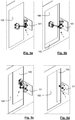
- Fig. 1 shows the hinge device 1 object of the invention, fastened to a frame 101 of a vehicle and a door 100 thereof, in an intermediate position between a closed door and an open door 100.
- Fig. 2 shows the same hinge device 1 but isolated and in a closed door 100 position ( Fig. 2 ).
- the hinge device 1 for performing the opening and closing of the door 100 fastened to the frame 101 is configured so that the door 100 does not change orientation during said operation, as observed in figures 5a to 5d , which sequentially show the positions of the components of the hinge device 1 from the closed door 100 position to the open door 100 position.
- the path of the linking means 7 comprises a first segment 71 and a second segment 72.
- the first segment 71 extends between the first end contact points 51 and 61 of the pulley grooves 5 and 6, while the second segment 72 extends between the second end contact points 52 and 62 of the pulley grooves 5 and 6.
- the path of the linking means 7 comprises at least one crossing of segments wherein the first segment 71 crosses the second segment 72.
- the path comprises two crossings P1 and P2, as shown in Fig. 3 .
- the arm 2 comprises, in addition to the two diverting elements 8, a central diverting element 9 arranged on the bend of the arm 2, the contour surface of which is convex-curved, having a diameter smaller than the diameter of any of the pulley bodies 5 and 6.
- Fig. 4 clearly shows that one side of the contour surface of the central diverting element 9 is in contact with both the first segment 71 and the second segment 72 of the path of the linking means. In other words, a crossing of segments as such does not occur on the central diverting element 9.
- first segment 71 and the second segment 72 of the path of the linking means 7 run at different heights at least between a diverting element 8 and the central diverting element 9, such that the contact section of the part of the linking means 7 that follow the first segment 71 with the convex-curved contour surface of the central diverting element 9 is located vertically above or below the contact section of the part of the linking means 7 that follow the second segment 71 with the convex-curved contour surface of the central diverting element 9.
- the vertical direction is a direction parallel to that of the rotation axes with respect to which the ends of the arm 2 pivot. This vertical arrangement of the segments 71 and 72 can be seen in Figs. 4 and 6a-6d .
- crossings P1 and P2 between the first segment 71 and the second segment 72 occur at different heights, one segment being located at a height that is different from that of the other, and being considered a height measured according to a direction parallel to that of the rotation axes with respect to which the ends of the arm 2 pivot.
- each belt is made up of a casing or sheath 75 that contains a plurality of cords 70 arranged in parallel and formed by filiform elements, preferably intertwined.
- the filiform elements are preferably made from steel or aramid.
- the sheath 75 is a polymeric material, preferably of polyurethane.
- Each filiform element 73 and 74 has a first end and a second end that are fixed in a removable way and respectively to the pulley grooves of the first pulley 5 and the second pulley 6.
- the first end 73a of the filiform element 73 is shown in Fig. 8 .
- the groove of the first pulley 5 is arranged on a plate or sheet configured to clip and keep said end retained.
Landscapes
- Engineering & Computer Science (AREA)
- Mechanical Engineering (AREA)
- Power-Operated Mechanisms For Wings (AREA)
- Hinges (AREA)
- Devices For Conveying Motion By Means Of Endless Flexible Members (AREA)
- Closing And Opening Devices For Wings, And Checks For Wings (AREA)
- Hinge Accessories (AREA)
Description
- The present invention relates to a hinge device for opening and closing a door of a vehicle such as a bus, configured so that the door remains parallel to the side of the vehicle that it is attached to at all times.
- In public transportation vehicles, such as buses, it is increasingly common for doors to be mounted on the frame or body of the vehicle by means of hinges designed to open and close the door, such that said door does not change orientation and remains parallel to the frame. A hinge device such that said door does not change orientation and remains parallel to the frame is known from
US5289615 . - The publication of European patent application
EP2333216-A1 , in its section on the description of the state of the art, refers to the Figs. 15 and 16 thereof, which pertain to a hinge for buses that opens and closes the door, keeping the door parallel at all times. - As explained in this section, the link of said Fig. 15 is connected to a vehicle body of a bus and its door. The end of the link is connected to an axis part of the vehicle body rotatably and the other end of the link is connected to an axis part of the door rotatably. Besides, a first pulley is connected integrally with the axis part of the vehicle body and a second pulley is connected integrally with the axis part of the door. Between the first pulley and the second pulley, a timing belt is placed thereover. In the explanation of the operation of the hinge device during opening and closing, it is indicated that the attitude of the door relative to the vehicle body is defined by combination of the rotation angle of the link relative to the axis part of the vehicle body and the rotation angle of the second pulley relative to the link. As the rotation angle of the link and the rotation angle of the second pulley relative to the link cancel out each other, when opening or closing the door, the attitude of the door is maintained fixed and the door is pivoted around the axis part of the vehicle body while it keeps parallel with the back-and-forth direction of the vehicle body.
- It also indicates that the axis part of the vehicle is fixed to the inner surface of the vehicle body and the axis part of the door is fixed to the back surface of the door. Therefore, if the open angle of the door is to be increased, the link interferes with the inner surface of the vehicle body and the open angle of the door cannot be increased. In order to increase the open angle of the door, as illustrated in Fig. 16, the link and the timing belt are bent into an L shape at their midpoint so as to prevent interference of the link and the timing belt with the inner surface of the vehicle body.
- In
EP2333216-A1 , the Japanese patent applicationJP2007-523278 ES2296135-T3 ES2296135-T3 Figs. 1 and 2 of this patent, whereinFig. 1 does not belong to the invention claimed inES2296135-T3 - The difference between the hinge devices of
Figs. 1 and 2 ofES2296135-T3 Fig. 1 , the two pulleys are circular and have the same diameter, such that, upon movement from a closed position between the posts to an open position, the door always maintains the same orientation. On the other hand, in the device ofFig. 2 , according to the invention claimed in said document, at least one of the pulleys is not circular. Other embodiments are also described in which the arms have an angled shape, such as inFigs. 4 and5 . The timing belt on the inside of the arm is guided by two rollers at an angle of 90°. The two pulleys around which the timing belt loops are elliptical. - The invention object of the document
EP2333216-A1 and of the patentUS 8,365,359 consists of a hinge device for opening and closing a second member (such as a door) relative to a first member (such as the frame of a vehicle). The device comprises a first mounting element mounted on the first member and having an axis part; a second mounting element mounted on the second member and having an axis part; a first pulley fixed to the axis part of the first mounting element; a second pulley fixed to the axis part of the second mounting element; a looping member that runs between the first pulley and the second pulley; a connecting member that is connected to the part of the first mounting element to be rotatable with respect to the first mounting element and connected to the axis part of the second mounting element to be rotatable with respect to the second mounting element; and an abutting part that abuts to the outside of the looping member in such a manner that a width between one side of the looping element and the opposite side thereof becomes smaller than the diameter of at least one of the pulleys. - The figures of
EP2333216-A1 andUS 8,365,359 show that the connecting member is a straight, not angled, element, and the looping member is a closed belt with ends that loop around the two pulleys. The abutting part has several elements that make the belt narrower at the outlet of each of the two pulleys. - Another document is the United States patent application
US2007084016-A1 , which refers to a hinge device comprising a lever that is provided with two end parts, which are used for assembling the lever to a door or hood or a frame and are pivotable about pins located at the ends of the lever, respectively. The invention particularly relates to a hinge device for a rotatable and pivotable door that can pivot open in a parallel fashion, as a pantograph-type door. ItsFigs. 3 and 4 show a special embodiment of the device in which the lever has an angled shape with its articulated ends. Along the inside of the angled lever is a toothed belt (see traction ropes) arranged wrapped around disks and the shape thereof is maintained by the arrangement of deflection rollers. - One of the disadvantages of the types of hinges like those described is that the belts tend to loosen over time and the entire device must be dismounted to reach the right tension for opening and closing the door, which takes time and labor. It is also desirable for the door to remain parallel to the frame of the vehicle at all times during opening and closing operations, without any of its edges protruding at an incline to avoid accidents. Furthermore, it is also preferable that the hinge device is formed by components that are accessible and available on the market, without having to use non-conventional pulleys, which occupies the least amount of space possible and with components that interfere as little as possible with the surroundings, in other words, that they are not an obstacle to the entry and exit of passengers.
- For the purpose of providing an alternative solution, a hinge device for operating the opening and closing of a door fastened to the frame of a vehicle, configured so that the door does not change orientation during said operation, is made known. The hinge device comprises an arm provided with two ends attached in a pivotable way, around parallel rotation axes, to respective mounting bodies, one being fixable to the door and the other to the frame of the vehicle. Each mounting body comprises, coinciding with each associated end of the arm, a concentric pulley body with a respective rotation axis and fixed to a respective mounting body. The hinge device further comprises linking means that extend along the arm and rest on the pulley grooves, being partially rolled up, and two end contact points being determined on the linking means for each of the pulley grooves.
- Essentially, the hinge device of the invention is characterized in that the arm has an angled shape, having two angled sections configured in a general L shape, in that the path of the linking means comprises a first segment and a second segment, the first segment being the one that extends between the first end contact points of the pulley grooves and the second segment being the one that extends between the second end contact points of the pulley grooves, and in that the path of the linking means comprises at least one crossing of segments, wherein the first segment crosses the second segment. The arm comprises at least one diverting element arranged on one of its angled sections, between the bend of the arm and one of the pulley bodies, the contour surface of which is convex-curved, having a diameter smaller than the diameter of any of the pulley bodies, and where one of its sides is in contact with the first segment and another one of its sides is in contact with the second segment of the path of the linking means, the arm at least one diverting element being arranged such that the crossing of segments is located between the diverting element and the pulley body located on the same section of the arm upon which the diverting element is arranged. In addition to the at least one diverting element, the arm comprises a central diverting element arranged on the bend of the arm, the contour surface of which is convex-curved, having a diameter smaller than the diameter of any of the pulley bodies, and where one of its sides is in contact with both the first segment and the second segment of the path of the linking means.
- According to another characteristic of the invention, the arm comprises at least two diverting elements, each one arranged on one of its angled sections, between the bend of the arm and one of the pulley bodies, the contour surface of which is convex-curved and having a diameter smaller than the diameter of any of the pulley bodies. Each one of the two diverting elements is in contact on one of its sides with the first segment and another one of its sides is in contact with the second segment of the path of the linking means, each diverting element being arranged such that there is a crossing of segments located between each diverting element and the corresponding pulley body located on the same angled section of the arm upon which the diverting element is arranged.
- According to another characteristic of the invention, the first segment and the second segment of the path of the linking means run at different heights at least between a diverting element and the central diverting element, such that the contact section of the part of the linking means that follow the first segment with the convex-curved contour surface of the central diverting element is located vertically above or below the contact section of the part of the linking means that follow the second segment with the convex-curved contour surface of the central diverting element, the vertical direction being a direction parallel to that of the rotation axes with respect to which the ends of the arm pivot.
- According to another characteristic of the invention, at least one crossing between the first segment and the second segment of the path of the linking means occurs at a different height, one segment being located at a height that is different than that of the other, and being considered a height measured according to a direction parallel to that of the rotation axes with respect to which the ends of the arm pivot.
- According to another characteristic of the invention, the convex-curved contour surfaces of the central diverting element and of the diverting element or elements are provided with perimeter slots for guiding the contact of the linking means with said surfaces.
- According to another characteristic of the invention, the arm comprises, in addition to the at least one diverting element, a central diverting element arranged on the bend of the arm, the contour surface of which is convex-curved, having a diameter smaller than the diameter of any of the pulley bodies, and where one of its sides is in contact with both the first segment and the second segment of the path of the linking means.
- According to a preferred embodiment of the invention, the arm comprises at least two diverting elements, each one arranged on one of its angled sections, between the bend and one of the pulley bodies, the contour surface of which is convex-curved and has a diameter smaller than the diameter of any of the pulley bodies, each one of the two diverting elements being in contact on one of its sides with the first segment and another one of its sides being in contact with the second segment of the path of the linking means and each diverting element being arranged such that there is a crossing of segments located between each diverting element and the corresponding pulley body located on the same angled section of the arm upon which the diverting element is arranged.
- According to another characteristic of the invention, the first segment and the second segment of the path of the linking means run at different heights at least between a diverting element and the central diverting element, such that the contact section of the part of the linking means that follow the first segment with the convex-curved contour surface of the central diverting element is vertically located above or below the contact section of the part of the linking means that follow the second segment with the convex-curved contour surface of the central diverting element, the vertical direction being a direction parallel to that of the rotation axes with respect to which the ends of the arm pivot.
- According to another characteristic of the invention, the at least one crossing between the first segment and the second segment of the path of the linking means occurs at a different height, one segment being located at a height that is different than that of the other, and being considered a height measured according to a direction parallel to that of the rotation axes with respect to which the ends of the arm pivot.
- Preferably, the convex-curved contour surfaces of the central diverting element and of the diverting element or elements are provided with perimeter slots for guiding the contact of the linking means with said surfaces.
- Also preferably, the pulley grooves comprise two perimeter portions located at different heights around the respective pulley body, or they are configured according to a helical path around the respective pulley body for guiding the contact of the linking means with the pulley grooves.
- According to another characteristic of the invention, the central diverting element is formed by a prismatic body with an elliptical base, with the ability to rotate around an axis parallel to the rotation axes with respect to which the ends of the arm pivot, said axis of the central diverting element being firmly attached to the arm, and being locked in a specific rotation position wherein the linking means adopt a state of tension upon contact with the central diverting element.
- The linking means can be formed by at least a belt, a cable, a filiform element or a chain. According to a preferred embodiment of the invention, the linking means comprise at least a flat belt made up of a sheath that contains a plurality of cords arranged in parallel and formed by filiform elements, preferably intertwined. The filiform elements can be made from steel or aramid. The sheath is a polymeric material, preferably of polyurethane.
- According to the preferred embodiment, the linking means in particular comprise two flat belts as described previously, wherein one belt follows the path of the first segment and the other belt follows the path of the second segment.
- According to another characteristic of this preferred embodiment, the first ends and the second ends of each belt are fixed in a removable way and respectively to the pulley grooves of the first pulley and the second pulley.
- Advantageously, according to another characteristic of this preferred embodiment, the two belts of the linking means have the same length, which greatly facilitates mounting of the hinge device.
- According to another characteristic of the invention, the mounting body that may be fixed to the door houses in its interior a motor with a rotation axis that causes the arm to rotate.
- The accompanying drawings illustrate by way of non-limiting example, a preferred embodiment of the hinge device object of the invention. In said drawings:
-
Fig. 1 is a perspective view of the hinge device object of the invention, fastened to a frame of a vehicle and to a door thereof, in an intermediate position between a closed door and an open door; -
Fig. 2 is a perspective view of the hinge device object of the invention, in a closed door position; -
Fig. 3 is a plan view of the inside of the hinge device ofFig. 2 ; -
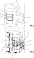
Fig. 4 is a perspective view of the hinge device ofFig. 2 , however some outer parts of the arm are not shown in order to show the arrangement of the central diverting element and the diverting element that comes in contact with the first segment of the path of the linking means; -
Figs. 5a, 5b, 5c and 5d are perspective views of the hinge device object of the invention fastened to the frame of a vehicle and the door thereof at different positions that range from a closed door position to an open door position, respectively, wherein the device is shown without the outer part of the arm in order to show the elements arranged therein; -
Figures 6a, 6b ,6c and 6d are enlarged views of the hinge device shown inFigs. 5a, 5b, 5c and 5d , respectively; -
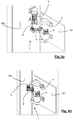
Fig. 7 is a detailed view of the end of the arm attached to the mounting body fixed to the door, partially uncovered to show the first pulley grooves; -
Fig. 8 shows another detailed view of the arm attached to the mounting body fixed to the door, partially uncovered to show grooves of the first pulley and the perimeter slots of the closest diverting body; and -
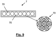
Fig. 9 is a detailed view of the transverse cross section of one of the two flat belts that make up the linking means according to the preferred embodiment of the invention. -
Fig. 1 shows thehinge device 1 object of the invention, fastened to aframe 101 of a vehicle and adoor 100 thereof, in an intermediate position between a closed door and anopen door 100.Fig. 2 shows thesame hinge device 1 but isolated and in aclosed door 100 position (Fig. 2 ). Thehinge device 1 for performing the opening and closing of thedoor 100 fastened to theframe 101 is configured so that thedoor 100 does not change orientation during said operation, as observed infigures 5a to 5d , which sequentially show the positions of the components of thehinge device 1 from theclosed door 100 position to theopen door 100 position. -
Figures 1 and 2 show that thehinge device 1 comprises anarm 2 provided with two ends attached in a pivotable way, around parallel rotation axes, to respective mountingbodies first mounting body 3 can be fixed to thedoor 100 by a bolt joint plate or by any other form of conventional fastening (seeFig. 8 ), while the second mountingbody 4 can be fixed in a similar way to theframe 101 of the vehicle, at a short distance from theopening 102 of theframe 101 where thedoor 100 fits, as shown inFig. 1 . The mountingbody 3 that may be fixed to thedoor 100 houses in its interior a motor with a rotation axis that causes thearm 2 to rotate to open and close the door 100 (seefigures 5a to 5d ). - Each mounting
body arm 2, aconcentric pulley body body Fig. 3 , wherein thepulley body 5 forms part of the first mountingbody 3 and thepulley body 6 forms part of the second mountingbody 4. -
Fig. 3 also shows that thehinge body 1 further comprises linking means 7 that extend along thearm 2 and rest on thepulley grooves pulley grooves first pulley second pulley 6. - On the
hinge device 1, it is worth noting that thearm 2 has an angled shape, such that twoangled sections Figs. 1 to 3 show the angled shape of thearm 2, since the other figures do not show part of thearm 2 in order to show the linking means 7 that run along its interior and other components that will be explained further on. - In
Figs. 1-4 and6a-6d it is easy to see that the path of the linking means 7 comprises afirst segment 71 and asecond segment 72. Thefirst segment 71 extends between the first end contact points 51 and 61 of thepulley grooves second segment 72 extends between the second end contact points 52 and 62 of thepulley grooves first segment 71 crosses thesecond segment 72. In fact, in thehinge device 1 shown in the drawings, the path comprises two crossings P1 and P2, as shown inFig. 3 . - Furthermore,
Fig. 3 shows that thearm 2 comprises two divertingelements 8, each one arranged on one of itsangled sections arm 2 and acorresponding pulley body pulley bodies elements 8 is in contact on one of its sides with thefirst segment 71 and another one of its sides is in contact with thesecond segment 72 of the path of the linking means 7. Each divertingelement 8 is arranged such that there is a crossing P1, P2 of segments located between each divertingelement 8 and thecorresponding pulley body angled section arm 2 upon which the divertingelement 8 is arranged. - The
arm 2 comprises, in addition to the two divertingelements 8, a central divertingelement 9 arranged on the bend of thearm 2, the contour surface of which is convex-curved, having a diameter smaller than the diameter of any of thepulley bodies Fig. 4 clearly shows that one side of the contour surface of the central divertingelement 9 is in contact with both thefirst segment 71 and thesecond segment 72 of the path of the linking means. In other words, a crossing of segments as such does not occur on the central divertingelement 9. - In fact, the
first segment 71 and thesecond segment 72 of the path of the linking means 7 run at different heights at least between a divertingelement 8 and the central divertingelement 9, such that the contact section of the part of the linking means 7 that follow thefirst segment 71 with the convex-curved contour surface of the central divertingelement 9 is located vertically above or below the contact section of the part of the linking means 7 that follow thesecond segment 71 with the convex-curved contour surface of the central divertingelement 9. In light of the above, it is considered that the vertical direction is a direction parallel to that of the rotation axes with respect to which the ends of thearm 2 pivot. This vertical arrangement of thesegments Figs. 4 and6a-6d . - Furthermore, the crossings P1 and P2 between the
first segment 71 and thesecond segment 72 occur at different heights, one segment being located at a height that is different from that of the other, and being considered a height measured according to a direction parallel to that of the rotation axes with respect to which the ends of thearm 2 pivot. - To favor the vertical arrangement of the
first segment 71 with respect to thesecond segment 72, the convex-curved contour surface of the central divertingelement 9 and of the divertingelements 8 are provided with perimeter slots for guiding the contact of the linking means 7 with said surfaces (seeFig. 8 ). - For the same purpose, the
pulley grooves respective pulley body respective pulley body pulley grooves Figs. 6d ,7 and 8 . - The central diverting
element 9 is formed by a prismatic body with an elliptical base, with the ability to rotate around an axis parallel to the rotation axes with respect to which the ends of thearm 2 pivot. The axis of the central divertingelement 9 is firmly attached to thearm 2. Advantageously, the central divertingelement 9 is able to be locked in a specific rotation position wherein the linking means 7 adopt a state of tension upon contact with the central divertingelement 9. Thus, thanks to the configuration of its elliptical base, when it rotates vertically, the distance from its rotation center to its contact surface with thesegments - Although the linking means can be formed by a single element, preferably a flat belt that follows the path indicated, with variations in height depending on the segment, the linking means 7 preferably comprise two elements in the form of flat straps or
belts 73 and 74 (seeFig. 7 ), wherein abelt 73 follows the path of thefirst segment 71 and theother belt 74 follows the path of thesecond segment 72. The twoflat belts hinge device 1, since it is not necessary to distinguish one from the other. - Preferably, as shown in
Fig. 9 , corresponding to the section according to a transverse cross section of one of theflat belts cords 70 arranged in parallel and formed by filiform elements, preferably intertwined. The filiform elements are preferably made from steel or aramid. The sheath 75 is a polymeric material, preferably of polyurethane. - Each
filiform element first pulley 5 and thesecond pulley 6. Thefirst end 73a of thefiliform element 73 is shown inFig. 8 . In order to fix thefirst end 73a, the groove of thefirst pulley 5 is arranged on a plate or sheet configured to clip and keep said end retained.
Claims (13)
- A hinge device (1) for operating the opening and closing of a door (100) fastened to a frame (101) of a vehicle, configured so that the door (100) does not change orientation during said operation, wherein the hinge device (1) comprises an arm (2) provided with two ends attached in a pivotable way, around parallel rotation axes, to respective mounting bodies (3, 4), one being fixable to the door (100) and the other to the frame (101) of the vehicle, wherein each mounting body (3, 4) comprises, coinciding with each associated end of the arm (2), a concentric pulley body (5, 6) with a respective rotation axis and fixed to a respective mounting body (3, 4), and the hinge device (1) further comprising linking means (7) that extend along the arm (2) and rest on the pulley grooves (5, 6), being partially rolled up determining two end contact points (51, 52; 61, 62) on the linking means (7) with each of the pulley grooves (5, 6), wherein the arm (2) has an angled shape, having two angled sections (21, 22) configured in a general L shape, in that the path of the linking means (7) comprises a first segment (71) and a second segment (72), the first segment (71) being the one that extends between the first end contact points (51, 61) of the pulley grooves (5, 6) and the second segment (72) being the one that extends between the second end contact points (52, 62) of the pulley grooves (5, 6), and wherein the arm (2) comprises a central diverting element (9) arranged on the bend of the arm (2), the contour surface of which is convex-curved, and where one of its sides is in contact with both the first segment (71) and the second segment (72) of the path of the linking means (7), characterized in that the path of the linking means (7) comprises at least one crossing (P1, P2) of segments, wherein the first segment (71) crosses the second segment (72), in that the arm (2) comprises, in addition to the central diverting element (9), at least one diverting element (8) arranged on one of its angled sections (21, 22), between the bend of the arm and one of the pulley bodies (5, 6), the contour surface of which is convex-curved, having a diameter smaller than the diameter of any of the pulley bodies (5, 6), and where one of its sides is in contact with the first segment (71) and another one of its sides is in contact with the second segment (72) of the path of the linking means (7), the at least one diverting element (8) being arranged such that the crossing (P1, P2) of segments is located between the diverting element (8) and the pulley body (5, 6) located on the same section (21, 22) of the arm (2) upon which the diverting element is arranged (8), and in that the central diverting element (9) arranged on the bend of the arm (2), has a diameter smaller than the diameter of any of the pulley bodies (5, 6).
- The hinge device (1) according to claim 1, wherein the arm (2) comprises at least two diverting elements (8), each one arranged on one of its angled sections (21, 22), between the bend of the arm and one of the pulley bodies (5, 6), the contour surface of which is convex-curved and has a diameter smaller than the diameter of any of the pulley bodies (5, 6), each one of the two diverting elements (8) being in contact on one of its sides with the first segment (71) and another one of its sides being in contact with the second segment (72) of the path of the linking means (7), and each diverting element (8) is arranged such that there is a crossing (P1, P2) of segments located between each diverting element (8) and the corresponding pulley body (5, 6) located on the same angled section (21, 22) of the arm (2) upon which the diverting element (8) is arranged.
- The hinge device (1) according to claim 1 or 2, wherein the first segment (71) and the second segment (72) of the path of the linking means (7) run at different heights at least between a diverting element (8) and the central diverting element (9), such that the contact section of the part of the linking means (7) that follow the first segment (71) with the convex-curved contour surface of the central diverting element (9) is located vertically above or below the contact section of the part of the linking means (7) that follow the second segment (71) with the convex-curved contour surface of the central diverting element (9), the vertical direction being a direction parallel to that of the rotation axes with respect to which the ends of the arm (2) pivot.
- The hinge device (1) according to any one of the preceding claims, wherein the at least one crossing (P1, P2) between the first segment (71) and the second segment (72) of the path of the linking means (7) occurs at a different height, one segment being located at a height that is different than that of the other, being considered a height measured according to a direction parallel to that of the rotation axes with respect to which the ends of the arm (2) pivot.
- The hinge device (1) according to claims 3 and 4, wherein the convex-curved contour surfaces of the central diverting element (9) and of the diverting element or elements (8) are provided with perimeter slots for guiding the contact of the linking means (7) with said surfaces.
- The hinge device (1) according to claim 5, wherein the pulley grooves (5, 6) comprise two perimeter portions located at different heights around the respective pulley body (5, 6), or they are configured according to a helical path around the respective pulley body (5, 6) for guiding the contact of the linking means (7) with the pulley grooves (5, 6).
- The hinge device (1) according to any one of the claims 2 to 6, wherein the central diverting element (9) is formed by a prismatic body with an elliptical base, with the ability to rotate around an axis parallel to the rotation axes with respect to which the ends of the arm (2) pivot, said axis of the central diverting element (9) being firmly attached to the arm (2), and being locked in a specific rotation position wherein the linking means (7) adopt a state of tension upon contact with the central diverting element (9).
- The hinge device (1) according to any one of the preceding claims, wherein the linking means (7) comprise at least one belt (73, 74) or at least one filiform element.
- The hinge device (1) according to claim 8, wherein the linking means (7) comprise two belts (73, 74) and wherein one belt (73) follows the path of the first segment (71) and the other belt (74) follows the path of the second segment (72).
- The hinge device (1) according to claim 9, wherein the first ends and the second ends of each belt (73, 74) are fixed in a removable way and respectively to the pulley grooves of the first pulley (5) and the second pulley (6).
- The hinge device (1) according to claim 9 or 10, wherein the two belts (73, 74) of the linking means have the same length.
- The hinge device (1) according to any one of the claims 8 to 11, wherein the or each belt (73, 74) of the linking means (7) is flat and is made up of a sheath (75) that contains a plurality of cords (70) arranged in parallel and formed by intertwined filiform elements.
- The hinge device (1) according to any one of the preceding claims, wherein the mounting body (3) that may be fixed to the door (100) houses in its interior a motor with a rotation axis that causes the arm (2) to rotate.
Priority Applications (13)
| Application Number | Priority Date | Filing Date | Title |
|---|---|---|---|
| ES17382189T ES2858510T3 (en) | 2017-04-06 | 2017-04-06 | Hinge device for opening and closing a vehicle door |
| EP17382189.3A EP3385484B1 (en) | 2017-04-06 | 2017-04-06 | Hinge device for opening and closing a vehicle door |
| PT173821893T PT3385484T (en) | 2017-04-06 | 2017-04-06 | Hinge device for opening and closing a vehicle door |
| PL17382189T PL3385484T3 (en) | 2017-04-06 | 2017-04-06 | Hinge device for opening and closing a vehicle door |
| US16/500,978 US11560744B2 (en) | 2017-04-06 | 2018-04-05 | Hinge device for opening and closing a vehicle door |
| CN201880023645.3A CN110494622B (en) | 2017-04-06 | 2018-04-05 | Hinge device for opening and closing vehicle door |
| CA3056734A CA3056734A1 (en) | 2017-04-06 | 2018-04-05 | Hinge device for opening and closing a vehicle door |
| SG11201908801T SG11201908801TA (en) | 2017-04-06 | 2018-04-05 | Hinge device for opening and closing a vehicle door |
| BR112019020792-9A BR112019020792B1 (en) | 2017-04-06 | 2018-04-05 | HINGE DEVICE FOR OPENING AND CLOSING A VEHICLE DOOR |
| MYPI2019005456A MY202032A (en) | 2017-04-06 | 2018-04-05 | Hinge device for opening and closing a vehicle door |
| PCT/ES2018/070300 WO2018185358A2 (en) | 2017-04-06 | 2018-04-05 | Hinge device for opening and closing a vehicle door |
| MX2019011960A MX2019011960A (en) | 2017-04-06 | 2018-04-05 | Hinge device for opening and closing a vehicle door. |
| CONC2019/0010932A CO2019010932A2 (en) | 2017-04-06 | 2019-10-02 | Hinge device for opening and closing a vehicle door |
Applications Claiming Priority (1)
| Application Number | Priority Date | Filing Date | Title |
|---|---|---|---|
| EP17382189.3A EP3385484B1 (en) | 2017-04-06 | 2017-04-06 | Hinge device for opening and closing a vehicle door |
Publications (2)
| Publication Number | Publication Date |
|---|---|
| EP3385484A1 EP3385484A1 (en) | 2018-10-10 |
| EP3385484B1 true EP3385484B1 (en) | 2020-12-09 |
Family
ID=58578920
Family Applications (1)
| Application Number | Title | Priority Date | Filing Date |
|---|---|---|---|
| EP17382189.3A Active EP3385484B1 (en) | 2017-04-06 | 2017-04-06 | Hinge device for opening and closing a vehicle door |
Country Status (13)
| Country | Link |
|---|---|
| US (1) | US11560744B2 (en) |
| EP (1) | EP3385484B1 (en) |
| CN (1) | CN110494622B (en) |
| BR (1) | BR112019020792B1 (en) |
| CA (1) | CA3056734A1 (en) |
| CO (1) | CO2019010932A2 (en) |
| ES (1) | ES2858510T3 (en) |
| MX (1) | MX2019011960A (en) |
| MY (1) | MY202032A (en) |
| PL (1) | PL3385484T3 (en) |
| PT (1) | PT3385484T (en) |
| SG (1) | SG11201908801TA (en) |
| WO (1) | WO2018185358A2 (en) |
Families Citing this family (2)
| Publication number | Priority date | Publication date | Assignee | Title |
|---|---|---|---|---|
| JP6796613B2 (en) * | 2018-03-28 | 2020-12-09 | 三井金属アクト株式会社 | Switchgear and switchgear |
| US12006753B2 (en) * | 2022-01-31 | 2024-06-11 | Nissan North America, Inc. | Rear door assembly |
Family Cites Families (10)
| Publication number | Priority date | Publication date | Assignee | Title |
|---|---|---|---|---|
| GB504661A (en) * | 1938-01-08 | 1939-04-28 | Oscar Lyon Whittle | Improvements in and relating to cables, ropes, power transmitting belts and the like |
| US5289615A (en) * | 1991-11-08 | 1994-03-01 | The Boeing Company | Aircraft door hinge mechanism |
| EP0791710A1 (en) * | 1996-02-26 | 1997-08-27 | Julius Blum Gesellschaft m.b.H. | Wide-angle hinge |
| CN1218109C (en) * | 2000-07-06 | 2005-09-07 | 马尔提马蒂克公司 | Automatic open/close system for slide door |
| DE10325232B4 (en) | 2003-06-04 | 2005-05-25 | Adam Opel Ag | hinge device |
| DE102004008069B4 (en) | 2004-02-19 | 2006-04-27 | Adam Opel Ag | hinge device |
| ITVI20050254A1 (en) * | 2005-10-04 | 2007-04-05 | Besenzoni Spa | SAFETY MECHANISM, IN PARTICULAR FOR HANDLING DEVICES USED ON BOATS |
| EP2333216A4 (en) | 2008-09-12 | 2014-01-22 | Sugatsune Kogyo | Hinge device |
| EP2363560B1 (en) * | 2010-03-05 | 2013-01-02 | Parosha Holding B.V. | Door assembly |
| FR3029958B1 (en) * | 2014-12-12 | 2018-03-16 | Softica | DEVICE FOR DRIVING A SLIDING VANTAIL IN A DORMANT. |
-
2017
- 2017-04-06 PT PT173821893T patent/PT3385484T/en unknown
- 2017-04-06 PL PL17382189T patent/PL3385484T3/en unknown
- 2017-04-06 ES ES17382189T patent/ES2858510T3/en active Active
- 2017-04-06 EP EP17382189.3A patent/EP3385484B1/en active Active
-
2018
- 2018-04-05 WO PCT/ES2018/070300 patent/WO2018185358A2/en active Application Filing
- 2018-04-05 CA CA3056734A patent/CA3056734A1/en active Pending
- 2018-04-05 CN CN201880023645.3A patent/CN110494622B/en active Active
- 2018-04-05 MY MYPI2019005456A patent/MY202032A/en unknown
- 2018-04-05 US US16/500,978 patent/US11560744B2/en active Active
- 2018-04-05 MX MX2019011960A patent/MX2019011960A/en unknown
- 2018-04-05 SG SG11201908801T patent/SG11201908801TA/en unknown
- 2018-04-05 BR BR112019020792-9A patent/BR112019020792B1/en active IP Right Grant
-
2019
- 2019-10-02 CO CONC2019/0010932A patent/CO2019010932A2/en unknown
Non-Patent Citations (1)
| Title |
|---|
| None * |
Also Published As
| Publication number | Publication date |
|---|---|
| ES2858510T3 (en) | 2021-09-30 |
| PT3385484T (en) | 2021-01-13 |
| CA3056734A1 (en) | 2018-10-11 |
| MX2019011960A (en) | 2019-11-07 |
| SG11201908801TA (en) | 2019-10-30 |
| CN110494622B (en) | 2021-04-02 |
| MY202032A (en) | 2024-03-29 |
| BR112019020792B1 (en) | 2023-10-10 |
| PL3385484T3 (en) | 2021-06-14 |
| WO2018185358A3 (en) | 2018-11-29 |
| CO2019010932A2 (en) | 2019-10-21 |
| WO2018185358A2 (en) | 2018-10-11 |
| BR112019020792A2 (en) | 2020-04-28 |
| EP3385484A1 (en) | 2018-10-10 |
| US11560744B2 (en) | 2023-01-24 |
| CN110494622A (en) | 2019-11-22 |
| US20200032568A1 (en) | 2020-01-30 |
Similar Documents
| Publication | Publication Date | Title |
|---|---|---|
| US11560744B2 (en) | Hinge device for opening and closing a vehicle door | |
| JP3606894B2 (en) | Door opening and closing device for vehicle sliding door | |
| US6584731B2 (en) | Vehicle window lifter with cable tensioning device | |
| CA2516139A1 (en) | Automotive fuel door assembly | |
| US20070096503A1 (en) | Hinge device | |
| US7441749B2 (en) | Chain guide and drive mechanism including the same | |
| KR20010043312A (en) | Energy guiding chain | |
| WO1999035063A1 (en) | Conveyor device | |
| US20240058633A1 (en) | Horizontal lifeline shuttle apparatus | |
| CZ300096A3 (en) | Motor vehicle door fastener being structurally coupled with door hinge | |
| US9670709B2 (en) | Main door for the control of the access opening to a compartment, particularly a garage compartment | |
| US6935071B2 (en) | Powered sliding device for vehicle slide door | |
| US8789816B2 (en) | Hand protection safety apparatus for use with sheaves and pulleys | |
| EP1715126A2 (en) | Door closer device | |
| US5519920A (en) | Hinge | |
| EP0420907A1 (en) | Belt conveyor. | |
| US7806012B2 (en) | Attachment assembly and drive unit having same | |
| US3584414A (en) | Door control mechanism | |
| US9523231B2 (en) | Attachment assembly and drive unit having same | |
| EP0119224A1 (en) | Mechanical door opening and closing device | |
| US20060112776A1 (en) | Actuating device | |
| CH674397A5 (en) | ||
| US20180245392A1 (en) | Cable guide arrangement for a power-operated vehicle sliding door | |
| KR101459217B1 (en) | Door Closer | |
| DE10134592A1 (en) | Boot lid hinged to motor vehicle body via hinge arm has spiral displacement unit with two flexible traction elements fastened to it, to increase force of lid opening spring |
Legal Events
| Date | Code | Title | Description |
|---|---|---|---|
| PUAI | Public reference made under article 153(3) epc to a published international application that has entered the european phase |
Free format text: ORIGINAL CODE: 0009012 |
|
| STAA | Information on the status of an ep patent application or granted ep patent |
Free format text: STATUS: THE APPLICATION HAS BEEN PUBLISHED |
|
| AK | Designated contracting states |
Kind code of ref document: A1 Designated state(s): AL AT BE BG CH CY CZ DE DK EE ES FI FR GB GR HR HU IE IS IT LI LT LU LV MC MK MT NL NO PL PT RO RS SE SI SK SM TR |
|
| AX | Request for extension of the european patent |
Extension state: BA ME |
|
| STAA | Information on the status of an ep patent application or granted ep patent |
Free format text: STATUS: REQUEST FOR EXAMINATION WAS MADE |
|
| 17P | Request for examination filed |
Effective date: 20190220 |
|
| RBV | Designated contracting states (corrected) |
Designated state(s): AL AT BE BG CH CY CZ DE DK EE ES FI FR GB GR HR HU IE IS IT LI LT LU LV MC MK MT NL NO PL PT RO RS SE SI SK SM TR |
|
| GRAP | Despatch of communication of intention to grant a patent |
Free format text: ORIGINAL CODE: EPIDOSNIGR1 |
|
| STAA | Information on the status of an ep patent application or granted ep patent |
Free format text: STATUS: GRANT OF PATENT IS INTENDED |
|
| INTG | Intention to grant announced |
Effective date: 20200714 |
|
| GRAS | Grant fee paid |
Free format text: ORIGINAL CODE: EPIDOSNIGR3 |
|
| GRAA | (expected) grant |
Free format text: ORIGINAL CODE: 0009210 |
|
| STAA | Information on the status of an ep patent application or granted ep patent |
Free format text: STATUS: THE PATENT HAS BEEN GRANTED |
|
| AK | Designated contracting states |
Kind code of ref document: B1 Designated state(s): AL AT BE BG CH CY CZ DE DK EE ES FI FR GB GR HR HU IE IS IT LI LT LU LV MC MK MT NL NO PL PT RO RS SE SI SK SM TR |
|
| REG | Reference to a national code |
Ref country code: GB Ref legal event code: FG4D |
|
| REG | Reference to a national code |
Ref country code: AT Ref legal event code: REF Ref document number: 1343623 Country of ref document: AT Kind code of ref document: T Effective date: 20201215 Ref country code: CH Ref legal event code: EP |
|
| REG | Reference to a national code |
Ref country code: DE Ref legal event code: R096 Ref document number: 602017029187 Country of ref document: DE |
|
| REG | Reference to a national code |
Ref country code: IE Ref legal event code: FG4D |
|
| REG | Reference to a national code |
Ref country code: PT Ref legal event code: SC4A Ref document number: 3385484 Country of ref document: PT Date of ref document: 20210113 Kind code of ref document: T Free format text: AVAILABILITY OF NATIONAL TRANSLATION Effective date: 20210106 |
|
| REG | Reference to a national code |
Ref country code: FI Ref legal event code: FGE |
|
| REG | Reference to a national code |
Ref country code: NL Ref legal event code: FP |
|
| PG25 | Lapsed in a contracting state [announced via postgrant information from national office to epo] |
Ref country code: RS Free format text: LAPSE BECAUSE OF FAILURE TO SUBMIT A TRANSLATION OF THE DESCRIPTION OR TO PAY THE FEE WITHIN THE PRESCRIBED TIME-LIMIT Effective date: 20201209 Ref country code: NO Free format text: LAPSE BECAUSE OF FAILURE TO SUBMIT A TRANSLATION OF THE DESCRIPTION OR TO PAY THE FEE WITHIN THE PRESCRIBED TIME-LIMIT Effective date: 20210309 Ref country code: GR Free format text: LAPSE BECAUSE OF FAILURE TO SUBMIT A TRANSLATION OF THE DESCRIPTION OR TO PAY THE FEE WITHIN THE PRESCRIBED TIME-LIMIT Effective date: 20210310 |
|
| REG | Reference to a national code |
Ref country code: AT Ref legal event code: MK05 Ref document number: 1343623 Country of ref document: AT Kind code of ref document: T Effective date: 20201209 |
|
| PG25 | Lapsed in a contracting state [announced via postgrant information from national office to epo] |
Ref country code: BG Free format text: LAPSE BECAUSE OF FAILURE TO SUBMIT A TRANSLATION OF THE DESCRIPTION OR TO PAY THE FEE WITHIN THE PRESCRIBED TIME-LIMIT Effective date: 20210309 Ref country code: LV Free format text: LAPSE BECAUSE OF FAILURE TO SUBMIT A TRANSLATION OF THE DESCRIPTION OR TO PAY THE FEE WITHIN THE PRESCRIBED TIME-LIMIT Effective date: 20201209 Ref country code: SE Free format text: LAPSE BECAUSE OF FAILURE TO SUBMIT A TRANSLATION OF THE DESCRIPTION OR TO PAY THE FEE WITHIN THE PRESCRIBED TIME-LIMIT Effective date: 20201209 |
|
| PG25 | Lapsed in a contracting state [announced via postgrant information from national office to epo] |
Ref country code: HR Free format text: LAPSE BECAUSE OF FAILURE TO SUBMIT A TRANSLATION OF THE DESCRIPTION OR TO PAY THE FEE WITHIN THE PRESCRIBED TIME-LIMIT Effective date: 20201209 |
|
| REG | Reference to a national code |
Ref country code: LT Ref legal event code: MG9D |
|
| PG25 | Lapsed in a contracting state [announced via postgrant information from national office to epo] |
Ref country code: SK Free format text: LAPSE BECAUSE OF FAILURE TO SUBMIT A TRANSLATION OF THE DESCRIPTION OR TO PAY THE FEE WITHIN THE PRESCRIBED TIME-LIMIT Effective date: 20201209 Ref country code: RO Free format text: LAPSE BECAUSE OF FAILURE TO SUBMIT A TRANSLATION OF THE DESCRIPTION OR TO PAY THE FEE WITHIN THE PRESCRIBED TIME-LIMIT Effective date: 20201209 Ref country code: SM Free format text: LAPSE BECAUSE OF FAILURE TO SUBMIT A TRANSLATION OF THE DESCRIPTION OR TO PAY THE FEE WITHIN THE PRESCRIBED TIME-LIMIT Effective date: 20201209 Ref country code: EE Free format text: LAPSE BECAUSE OF FAILURE TO SUBMIT A TRANSLATION OF THE DESCRIPTION OR TO PAY THE FEE WITHIN THE PRESCRIBED TIME-LIMIT Effective date: 20201209 Ref country code: LT Free format text: LAPSE BECAUSE OF FAILURE TO SUBMIT A TRANSLATION OF THE DESCRIPTION OR TO PAY THE FEE WITHIN THE PRESCRIBED TIME-LIMIT Effective date: 20201209 |
|
| PG25 | Lapsed in a contracting state [announced via postgrant information from national office to epo] |
Ref country code: AT Free format text: LAPSE BECAUSE OF FAILURE TO SUBMIT A TRANSLATION OF THE DESCRIPTION OR TO PAY THE FEE WITHIN THE PRESCRIBED TIME-LIMIT Effective date: 20201209 |
|
| REG | Reference to a national code |
Ref country code: DE Ref legal event code: R097 Ref document number: 602017029187 Country of ref document: DE |
|
| PG25 | Lapsed in a contracting state [announced via postgrant information from national office to epo] |
Ref country code: IS Free format text: LAPSE BECAUSE OF FAILURE TO SUBMIT A TRANSLATION OF THE DESCRIPTION OR TO PAY THE FEE WITHIN THE PRESCRIBED TIME-LIMIT Effective date: 20210409 |
|
| REG | Reference to a national code |
Ref country code: ES Ref legal event code: FG2A Ref document number: 2858510 Country of ref document: ES Kind code of ref document: T3 Effective date: 20210930 |
|
| PLBE | No opposition filed within time limit |
Free format text: ORIGINAL CODE: 0009261 |
|
| STAA | Information on the status of an ep patent application or granted ep patent |
Free format text: STATUS: NO OPPOSITION FILED WITHIN TIME LIMIT |
|
| PG25 | Lapsed in a contracting state [announced via postgrant information from national office to epo] |
Ref country code: AL Free format text: LAPSE BECAUSE OF FAILURE TO SUBMIT A TRANSLATION OF THE DESCRIPTION OR TO PAY THE FEE WITHIN THE PRESCRIBED TIME-LIMIT Effective date: 20201209 |
|
| 26N | No opposition filed |
Effective date: 20210910 |
|
| PG25 | Lapsed in a contracting state [announced via postgrant information from national office to epo] |
Ref country code: SI Free format text: LAPSE BECAUSE OF FAILURE TO SUBMIT A TRANSLATION OF THE DESCRIPTION OR TO PAY THE FEE WITHIN THE PRESCRIBED TIME-LIMIT Effective date: 20201209 Ref country code: DK Free format text: LAPSE BECAUSE OF FAILURE TO SUBMIT A TRANSLATION OF THE DESCRIPTION OR TO PAY THE FEE WITHIN THE PRESCRIBED TIME-LIMIT Effective date: 20201209 Ref country code: MC Free format text: LAPSE BECAUSE OF FAILURE TO SUBMIT A TRANSLATION OF THE DESCRIPTION OR TO PAY THE FEE WITHIN THE PRESCRIBED TIME-LIMIT Effective date: 20201209 |
|
| PG25 | Lapsed in a contracting state [announced via postgrant information from national office to epo] |
Ref country code: LU Free format text: LAPSE BECAUSE OF NON-PAYMENT OF DUE FEES Effective date: 20210406 |
|
| PG25 | Lapsed in a contracting state [announced via postgrant information from national office to epo] |
Ref country code: LI Free format text: LAPSE BECAUSE OF NON-PAYMENT OF DUE FEES Effective date: 20210430 Ref country code: CH Free format text: LAPSE BECAUSE OF NON-PAYMENT OF DUE FEES Effective date: 20210430 |
|
| PG25 | Lapsed in a contracting state [announced via postgrant information from national office to epo] |
Ref country code: IE Free format text: LAPSE BECAUSE OF NON-PAYMENT OF DUE FEES Effective date: 20210406 |
|
| PG25 | Lapsed in a contracting state [announced via postgrant information from national office to epo] |
Ref country code: IS Free format text: LAPSE BECAUSE OF FAILURE TO SUBMIT A TRANSLATION OF THE DESCRIPTION OR TO PAY THE FEE WITHIN THE PRESCRIBED TIME-LIMIT Effective date: 20210409 |
|
| PG25 | Lapsed in a contracting state [announced via postgrant information from national office to epo] |
Ref country code: CY Free format text: LAPSE BECAUSE OF FAILURE TO SUBMIT A TRANSLATION OF THE DESCRIPTION OR TO PAY THE FEE WITHIN THE PRESCRIBED TIME-LIMIT Effective date: 20201209 |
|
| P01 | Opt-out of the competence of the unified patent court (upc) registered |
Effective date: 20230527 |
|
| PG25 | Lapsed in a contracting state [announced via postgrant information from national office to epo] |
Ref country code: HU Free format text: LAPSE BECAUSE OF FAILURE TO SUBMIT A TRANSLATION OF THE DESCRIPTION OR TO PAY THE FEE WITHIN THE PRESCRIBED TIME-LIMIT; INVALID AB INITIO Effective date: 20170406 |
|
| PG25 | Lapsed in a contracting state [announced via postgrant information from national office to epo] |
Ref country code: MK Free format text: LAPSE BECAUSE OF FAILURE TO SUBMIT A TRANSLATION OF THE DESCRIPTION OR TO PAY THE FEE WITHIN THE PRESCRIBED TIME-LIMIT Effective date: 20201209 |
|
| PGFP | Annual fee paid to national office [announced via postgrant information from national office to epo] |
Ref country code: CZ Payment date: 20240326 Year of fee payment: 8 Ref country code: PT Payment date: 20240325 Year of fee payment: 8 |
|
| PGFP | Annual fee paid to national office [announced via postgrant information from national office to epo] |
Ref country code: NL Payment date: 20240423 Year of fee payment: 8 |
|
| PGFP | Annual fee paid to national office [announced via postgrant information from national office to epo] |
Ref country code: TR Payment date: 20240327 Year of fee payment: 8 Ref country code: IT Payment date: 20240325 Year of fee payment: 8 Ref country code: BE Payment date: 20240329 Year of fee payment: 8 |
|
| PGFP | Annual fee paid to national office [announced via postgrant information from national office to epo] |
Ref country code: GB Payment date: 20240416 Year of fee payment: 8 |
|
| PGFP | Annual fee paid to national office [announced via postgrant information from national office to epo] |
Ref country code: DE Payment date: 20240418 Year of fee payment: 8 |
|
| PGFP | Annual fee paid to national office [announced via postgrant information from national office to epo] |
Ref country code: ES Payment date: 20240514 Year of fee payment: 8 |
|
| PGFP | Annual fee paid to national office [announced via postgrant information from national office to epo] |
Ref country code: FR Payment date: 20240425 Year of fee payment: 8 Ref country code: FI Payment date: 20240417 Year of fee payment: 8 |
|
| PGFP | Annual fee paid to national office [announced via postgrant information from national office to epo] |
Ref country code: PL Payment date: 20240402 Year of fee payment: 8 |
|
| PG25 | Lapsed in a contracting state [announced via postgrant information from national office to epo] |
Ref country code: MT Free format text: LAPSE BECAUSE OF FAILURE TO SUBMIT A TRANSLATION OF THE DESCRIPTION OR TO PAY THE FEE WITHIN THE PRESCRIBED TIME-LIMIT Effective date: 20201209 |