EP3385095A1 - Ultra super single tire for heavy duty - Google Patents
Ultra super single tire for heavy duty Download PDFInfo
- Publication number
- EP3385095A1 EP3385095A1 EP18163145.8A EP18163145A EP3385095A1 EP 3385095 A1 EP3385095 A1 EP 3385095A1 EP 18163145 A EP18163145 A EP 18163145A EP 3385095 A1 EP3385095 A1 EP 3385095A1
- Authority
- EP
- European Patent Office
- Prior art keywords
- belt
- edge
- spiral coil
- layer
- tread
- Prior art date
- Legal status (The legal status is an assumption and is not a legal conclusion. Google has not performed a legal analysis and makes no representation as to the accuracy of the status listed.)
- Granted
Links
Images



Classifications
-
- B—PERFORMING OPERATIONS; TRANSPORTING
- B60—VEHICLES IN GENERAL
- B60C—VEHICLE TYRES; TYRE INFLATION; TYRE CHANGING; CONNECTING VALVES TO INFLATABLE ELASTIC BODIES IN GENERAL; DEVICES OR ARRANGEMENTS RELATED TO TYRES
- B60C9/00—Reinforcements or ply arrangement of pneumatic tyres
- B60C9/18—Structure or arrangement of belts or breakers, crown-reinforcing or cushioning layers
-
- B—PERFORMING OPERATIONS; TRANSPORTING
- B60—VEHICLES IN GENERAL
- B60C—VEHICLE TYRES; TYRE INFLATION; TYRE CHANGING; CONNECTING VALVES TO INFLATABLE ELASTIC BODIES IN GENERAL; DEVICES OR ARRANGEMENTS RELATED TO TYRES
- B60C9/00—Reinforcements or ply arrangement of pneumatic tyres
- B60C9/18—Structure or arrangement of belts or breakers, crown-reinforcing or cushioning layers
- B60C9/20—Structure or arrangement of belts or breakers, crown-reinforcing or cushioning layers built-up from rubberised plies each having all cords arranged substantially parallel
-
- B—PERFORMING OPERATIONS; TRANSPORTING
- B60—VEHICLES IN GENERAL
- B60C—VEHICLE TYRES; TYRE INFLATION; TYRE CHANGING; CONNECTING VALVES TO INFLATABLE ELASTIC BODIES IN GENERAL; DEVICES OR ARRANGEMENTS RELATED TO TYRES
- B60C9/00—Reinforcements or ply arrangement of pneumatic tyres
- B60C9/18—Structure or arrangement of belts or breakers, crown-reinforcing or cushioning layers
- B60C9/20—Structure or arrangement of belts or breakers, crown-reinforcing or cushioning layers built-up from rubberised plies each having all cords arranged substantially parallel
- B60C9/22—Structure or arrangement of belts or breakers, crown-reinforcing or cushioning layers built-up from rubberised plies each having all cords arranged substantially parallel the plies being arranged with all cords disposed along the circumference of the tyre
-
- B—PERFORMING OPERATIONS; TRANSPORTING
- B60—VEHICLES IN GENERAL
- B60C—VEHICLE TYRES; TYRE INFLATION; TYRE CHANGING; CONNECTING VALVES TO INFLATABLE ELASTIC BODIES IN GENERAL; DEVICES OR ARRANGEMENTS RELATED TO TYRES
- B60C9/00—Reinforcements or ply arrangement of pneumatic tyres
- B60C9/02—Carcasses
- B60C9/16—Carcasses built-up with metallic reinforcing inlays
-
- B—PERFORMING OPERATIONS; TRANSPORTING
- B60—VEHICLES IN GENERAL
- B60C—VEHICLE TYRES; TYRE INFLATION; TYRE CHANGING; CONNECTING VALVES TO INFLATABLE ELASTIC BODIES IN GENERAL; DEVICES OR ARRANGEMENTS RELATED TO TYRES
- B60C9/00—Reinforcements or ply arrangement of pneumatic tyres
- B60C9/18—Structure or arrangement of belts or breakers, crown-reinforcing or cushioning layers
- B60C9/28—Structure or arrangement of belts or breakers, crown-reinforcing or cushioning layers characterised by the belt or breaker dimensions or curvature relative to carcass
-
- B—PERFORMING OPERATIONS; TRANSPORTING
- B60—VEHICLES IN GENERAL
- B60C—VEHICLE TYRES; TYRE INFLATION; TYRE CHANGING; CONNECTING VALVES TO INFLATABLE ELASTIC BODIES IN GENERAL; DEVICES OR ARRANGEMENTS RELATED TO TYRES
- B60C9/00—Reinforcements or ply arrangement of pneumatic tyres
- B60C9/18—Structure or arrangement of belts or breakers, crown-reinforcing or cushioning layers
- B60C9/20—Structure or arrangement of belts or breakers, crown-reinforcing or cushioning layers built-up from rubberised plies each having all cords arranged substantially parallel
- B60C2009/2012—Structure or arrangement of belts or breakers, crown-reinforcing or cushioning layers built-up from rubberised plies each having all cords arranged substantially parallel with particular configuration of the belt cords in the respective belt layers
- B60C2009/2016—Structure or arrangement of belts or breakers, crown-reinforcing or cushioning layers built-up from rubberised plies each having all cords arranged substantially parallel with particular configuration of the belt cords in the respective belt layers comprising cords at an angle of 10 to 30 degrees to the circumferential direction
-
- B—PERFORMING OPERATIONS; TRANSPORTING
- B60—VEHICLES IN GENERAL
- B60C—VEHICLE TYRES; TYRE INFLATION; TYRE CHANGING; CONNECTING VALVES TO INFLATABLE ELASTIC BODIES IN GENERAL; DEVICES OR ARRANGEMENTS RELATED TO TYRES
- B60C9/00—Reinforcements or ply arrangement of pneumatic tyres
- B60C9/18—Structure or arrangement of belts or breakers, crown-reinforcing or cushioning layers
- B60C9/20—Structure or arrangement of belts or breakers, crown-reinforcing or cushioning layers built-up from rubberised plies each having all cords arranged substantially parallel
- B60C2009/2012—Structure or arrangement of belts or breakers, crown-reinforcing or cushioning layers built-up from rubberised plies each having all cords arranged substantially parallel with particular configuration of the belt cords in the respective belt layers
- B60C2009/2019—Structure or arrangement of belts or breakers, crown-reinforcing or cushioning layers built-up from rubberised plies each having all cords arranged substantially parallel with particular configuration of the belt cords in the respective belt layers comprising cords at an angle of 30 to 60 degrees to the circumferential direction
-
- B—PERFORMING OPERATIONS; TRANSPORTING
- B60—VEHICLES IN GENERAL
- B60C—VEHICLE TYRES; TYRE INFLATION; TYRE CHANGING; CONNECTING VALVES TO INFLATABLE ELASTIC BODIES IN GENERAL; DEVICES OR ARRANGEMENTS RELATED TO TYRES
- B60C9/00—Reinforcements or ply arrangement of pneumatic tyres
- B60C9/18—Structure or arrangement of belts or breakers, crown-reinforcing or cushioning layers
- B60C9/20—Structure or arrangement of belts or breakers, crown-reinforcing or cushioning layers built-up from rubberised plies each having all cords arranged substantially parallel
- B60C2009/2012—Structure or arrangement of belts or breakers, crown-reinforcing or cushioning layers built-up from rubberised plies each having all cords arranged substantially parallel with particular configuration of the belt cords in the respective belt layers
- B60C2009/2032—Structure or arrangement of belts or breakers, crown-reinforcing or cushioning layers built-up from rubberised plies each having all cords arranged substantially parallel with particular configuration of the belt cords in the respective belt layers characterised by the course of the belt cords, e.g. undulated or sinusoidal
-
- B—PERFORMING OPERATIONS; TRANSPORTING
- B60—VEHICLES IN GENERAL
- B60C—VEHICLE TYRES; TYRE INFLATION; TYRE CHANGING; CONNECTING VALVES TO INFLATABLE ELASTIC BODIES IN GENERAL; DEVICES OR ARRANGEMENTS RELATED TO TYRES
- B60C9/00—Reinforcements or ply arrangement of pneumatic tyres
- B60C9/18—Structure or arrangement of belts or breakers, crown-reinforcing or cushioning layers
- B60C9/20—Structure or arrangement of belts or breakers, crown-reinforcing or cushioning layers built-up from rubberised plies each having all cords arranged substantially parallel
- B60C2009/2038—Structure or arrangement of belts or breakers, crown-reinforcing or cushioning layers built-up from rubberised plies each having all cords arranged substantially parallel using lateral belt strips at belt edges, e.g. edge bands
-
- B—PERFORMING OPERATIONS; TRANSPORTING
- B60—VEHICLES IN GENERAL
- B60C—VEHICLE TYRES; TYRE INFLATION; TYRE CHANGING; CONNECTING VALVES TO INFLATABLE ELASTIC BODIES IN GENERAL; DEVICES OR ARRANGEMENTS RELATED TO TYRES
- B60C9/00—Reinforcements or ply arrangement of pneumatic tyres
- B60C9/18—Structure or arrangement of belts or breakers, crown-reinforcing or cushioning layers
- B60C9/20—Structure or arrangement of belts or breakers, crown-reinforcing or cushioning layers built-up from rubberised plies each having all cords arranged substantially parallel
- B60C2009/2041—Structure or arrangement of belts or breakers, crown-reinforcing or cushioning layers built-up from rubberised plies each having all cords arranged substantially parallel with an interrupted belt ply, e.g. using two or more portions of the same ply
-
- B—PERFORMING OPERATIONS; TRANSPORTING
- B60—VEHICLES IN GENERAL
- B60C—VEHICLE TYRES; TYRE INFLATION; TYRE CHANGING; CONNECTING VALVES TO INFLATABLE ELASTIC BODIES IN GENERAL; DEVICES OR ARRANGEMENTS RELATED TO TYRES
- B60C2200/00—Tyres specially adapted for particular applications
- B60C2200/06—Tyres specially adapted for particular applications for heavy duty vehicles
-
- B—PERFORMING OPERATIONS; TRANSPORTING
- B60—VEHICLES IN GENERAL
- B60C—VEHICLE TYRES; TYRE INFLATION; TYRE CHANGING; CONNECTING VALVES TO INFLATABLE ELASTIC BODIES IN GENERAL; DEVICES OR ARRANGEMENTS RELATED TO TYRES
- B60C2200/00—Tyres specially adapted for particular applications
- B60C2200/06—Tyres specially adapted for particular applications for heavy duty vehicles
- B60C2200/065—Tyres specially adapted for particular applications for heavy duty vehicles for construction vehicles
Definitions
- the present invention relates to an ultra super single tire for heavy duty, and more particularly, the invention relates to an ultra super single tire for heavy duty, which has an increased ground contact length at the ground contacting center and has enhanced durability at the edges of the belt layer.
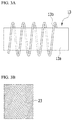
- a spiral coil belt (13) is a belt having a structure in which a single wire (13b) is continuously wound around a belt drum (13a) as illustrated in FIG. 3A , and this spiral coil belt is distinguished from a sheet type belt (23) that has been processed into a sheet form such as illustrated in FIG. 3B and contains cut wires.
- the technology of inserting a rubber sheet into the tread center portion has a problem that the tire weight is excessively increased, excessive heat generation occurs, durability of the tire is decreased, and the insertion effects are negligible.
- the technology of increasing the rubber thickness at the tread center has a problem that the tire weight is increased, and the effects are negligible.
- the technology of inserting a helical coil into the tire tread portion has a problem that the insertion effects are negligible.
- the belt durability and the footprint shape have been improved; however, there is a problem that as the air pressure allotment ratio increases, durability of the belt portion is decreased.
- the structure including a spiral coil belt of FIG. 2 is a five-layer belt structure; however, in the case of the belt edges, there is no substantial difference between the five-layer belt structure and a four-layer belt structure, and therefore, there is problem that the extent of risk has been rather increased.
- the technology of attaching a waved belt to the belt layer of the tire has a problem that the waved belt moves unnecessarily during driving, and durability of the tire is deteriorated.
- the present invention was contrived in order to solve problems such as described above, and an object of the invention is to provide an ultra super single tire for heavy duty, which has a four-layer belt structure while the order of lamination of the helical coil has been changed, the ground contact length of the ground contacting center has been further increased by means of a wide spiral coil belt having an increased width and an extender belt, and durability at the edges of the belt layer has been further enhanced.
- the ultra super single tire for heavy duty includes a tread that contacts the road surfaces; a carcass that constitutes the skeleton of the tire; and a belt layer that is disposed between the tread and the carcass, in which the belt layer is composed of a first belt to a fourth belt laminated sequentially from the carcass toward the tread, the first belt includes an extender belt, and the second belt is a wide spiral coil belt.
- the level difference between an edge of the third belt and an edge of the wide spiral coil belt (second belt) is designated as S1
- the level difference between an edge of the wide spiral coil belt (second belt) and an edge of the extender belt is designated as S2
- the width of the extender belt is designated as EBw
- the angle of inclination at an edge of a first main belt of the first belt is in the range of 50° ⁇ 5°
- the angle of inclination at an edge of the wide spiral coil belt (second belt) is 0°
- the angle of inclination at an edge of the third belt and the angle of inclination at an edge of the fourth belt is in the range of 18° ⁇ 5°.
- the angle of inclination of the extender belt is different from the angle of inclination at an edge of the first main belt of the first belt.
- the angle of inclination of the extender belt is in the range of 10° ⁇ 5°.
- FIG. 4 is a diagram schematically illustrating a tire having a belt structure including the wide spiral coil belt and the extender belt according to an embodiment of the present invention
- FIG. 5 is a diagram showing a cross-section of the tread for explaining the belt laminated structure of FIG. 4 .
- the ultra super single tire for heavy duty (100) includes a tread (110) that contacts the road surface, a carcass (120) that constitutes the skeleton of the tire, and a belt layer (130) that is disposed between the tread (110) and the carcass (120).
- the tread (110) is a part that contacts the ground surface (road surface) and is formed from a rubber material.
- the carcass (120) is formed by stacking several sheets of cord plies formed from high-strength synthetic fibers, and forms the skeleton of the tire.
- the belt layer (130) is disposed between the tread (110) and the carcass (120), and is composed of a first belt (131), a second belt (132), a third belt (133), and a fourth belt (134) disposed sequentially from the carcass (120) toward the tread (110).
- the first belt (131) is composed of a first main belt (131a) and an extender belt (131b), and the second belt (132) is formed from a wide spiral coil belt (WSC).
- the extender belt (131b) is a belt made of a material that is identical or similar to that of the first main belt (131a), and is a belt extending from the first main belt (131a) only in the length in the width direction.
- the wide spiral coil belt (WSC) needs a level difference because in a case in which the belt is produced from spiral coils as illustrated in FIG. 6 (see FIG. 3A ), the belt layer of the lower layer (#1 belt) should support the spiral coil of the upper layer.
- a belt having a wider width than the belt layer of the lower layer (#1 belt) is the wide spiral coil belt (WSC), and the portion having an increased width in the belt layer of the lower layer in order to support the spiral coil of the upper layer is referred to as extender belt.
- S1 represents the level difference between an edge of the third belt (133) and an edge of the wide spiral coil belt (second belt, 132)
- S2 represents the level difference between an edge of the wide spiral coil belt (second belt, 132) and an edge of the extender belt (131b)
- EBw represents the width of the extender belt (131b).
- Their dimensional ranges are ranges satisfying the following relations: 7.5 mm ⁇ S1 ⁇ 15 mm, 20 mm ⁇ S2, and 20 mm ⁇ EBw.
- TW/2 represents the half tread width.
- the angle of inclination at an edge of the first main belt (131a) of the first belt (131) is in the range of 50° ⁇ 5°
- the angle of inclination at an edge of the wide spiral coil belt (second belt, 132) is 0°
- the angle of inclination at an edge of the third belt (133) and the angle of inclination at an edge of the fourth belt are respectively in the range of 18° ⁇ 5°.
- the angle of inclination of the extender belt (131b) is different from the angle of inclination at an edge of the first main belt (131a) of the first belt (131), and the angle of inclination of the extender belt (131b) is in the range of 10° ⁇ 5°.
- FIG. 7 is a table of comparison showing a comparison based on a computational analysis of the shear strain distributions for the belt structure of FIG. 2 (conventional) and a deformed belt structure in which the position of the spiral coil belt has been changed.
- FIG. 7 shows the shear strains generated at an edge of a belt layer at the time of compression and at the time of loading.
- Deformation 1 shows a five-layer belt (four belts + S belt) structure including a spiral coil belt (13) as a first layer on the carcass (CS);
- Deformation 2 shows a five-layer belt (four belts + S belt) structure including a spiral coil belt (13) as a second layer on the carcass (CS);
- Deformation 3 shows a five-layer belt (four belts + S belt) structure including a spiral coil belt (13) s a fourth layer on the carcass (CS); and
- Deformation 4 shows a five-layer belt (four belts + S belt) structure including a spiral coil belt (13) as a fifth layer on the carcass (CS).
- ISS interlaminar shear strain
- FIG. 8 is a table of comparison showing a comparison based on a computational analysis of the shear strain distributions between the belt layers in the belt structure of FIG. 2 (conventional) and the belt structure of FIG. 4 (present invention)
- FIG. 9 is a table of comparison showing a comparison based on a computational analysis of the footprints of the belt structure of FIG. 2 (conventional) and the belt structure of FIG. 4 (present invention).
- FIG. 8 it can be seen that in the structure of an Example of the present invention ( FIG. 4 ), the shear strain occurring at the belt edges was decreased by about 77% compared to the structure of a conventional example ( FIG. 2 ). As shown in FIG. 7 as such, it is understood that the shear strain that conventionally occurs at belt edges does not occur in the Example of the present invention.
- the ground contact length on the shoulder side is decreased in the Example of the present invention.
- the ground contact length on the shoulder side can be minimized when the structure of the present invention, which is accompanied by a phenomenon in which the ground contact length increases significantly compared to a computational analysis, is applied.
Landscapes
- Engineering & Computer Science (AREA)
- Mechanical Engineering (AREA)
- Tires In General (AREA)
Abstract
Description
- The present invention relates to an ultra super single tire for heavy duty, and more particularly, the invention relates to an ultra super single tire for heavy duty, which has an increased ground contact length at the ground contacting center and has enhanced durability at the edges of the belt layer.
- Regarding tires for heavy duty, ultra super single (USS) tires that replace dual wheel tires with single wheel tires have been used. As more of wide-base tires are used, there is a problem that the footprint shape becomes unstable, and the performance of tires is deteriorated. That is, tires for heavy duty have a problem that, as shown in
FIG. 1 , a phenomenon in which the ground contacting center (C) of the tread(S) is depressed occurs, and the shoulder side footprint length (SFL) is increased so that deterioration of the stability of steering and belt durability, as well as abnormal wear occur. Particularly, a heaving phenomenon caused by decreased rigidity at the ground contacting center occurs, and belt failures caused by an increase in the air distribution ratio at the tread have emerged as a critical problem. - In order to solve the problems such as described above, a technology of increasing the ground contact length at the tread center and decreasing the ground contact length on the shoulder sides has been developed. That is, there have been suggested a technology of inserting a rubber sheet into the tread center portion as disclosed in Korean Unexamined Patent Application No.
10-2011-0049422 (date of publication: May 12, 2011 - Furthermore, as illustrated in
FIG. 2 , a five-layer belt (four belts + S belt) (10) structure in which a spiral coil belt (13) is included as a third layer on the carcass (CS) has been conventionally disclosed. A spiral coil belt (13) is a belt having a structure in which a single wire (13b) is continuously wound around a belt drum (13a) as illustrated inFIG. 3A , and this spiral coil belt is distinguished from a sheet type belt (23) that has been processed into a sheet form such as illustrated inFIG. 3B and contains cut wires. - However, the technology of inserting a rubber sheet into the tread center portion has a problem that the tire weight is excessively increased, excessive heat generation occurs, durability of the tire is decreased, and the insertion effects are negligible. The technology of increasing the rubber thickness at the tread center has a problem that the tire weight is increased, and the effects are negligible.
- Furthermore, the technology of inserting a helical coil into the tire tread portion has a problem that the insertion effects are negligible. In the structure including a spiral coil belt as shown in
FIG. 2 , the belt durability and the footprint shape have been improved; however, there is a problem that as the air pressure allotment ratio increases, durability of the belt portion is decreased. The structure including a spiral coil belt ofFIG. 2 is a five-layer belt structure; however, in the case of the belt edges, there is no substantial difference between the five-layer belt structure and a four-layer belt structure, and therefore, there is problem that the extent of risk has been rather increased. - Furthermore, the technology of attaching a waved belt to the belt layer of the tire has a problem that the waved belt moves unnecessarily during driving, and durability of the tire is deteriorated.
- The present invention was contrived in order to solve problems such as described above, and an object of the invention is to provide an ultra super single tire for heavy duty, which has a four-layer belt structure while the order of lamination of the helical coil has been changed, the ground contact length of the ground contacting center has been further increased by means of a wide spiral coil belt having an increased width and an extender belt, and durability at the edges of the belt layer has been further enhanced.
- In order to solve the problems described above, the ultra super single tire for heavy duty according to an embodiment the present invention includes a tread that contacts the road surfaces; a carcass that constitutes the skeleton of the tire; and a belt layer that is disposed between the tread and the carcass, in which the belt layer is composed of a first belt to a fourth belt laminated sequentially from the carcass toward the tread, the first belt includes an extender belt, and the second belt is a wide spiral coil belt.
- When the level difference between an edge of the third belt and an edge of the wide spiral coil belt (second belt) is designated as S1, the level difference between an edge of the wide spiral coil belt (second belt) and an edge of the extender belt is designated as S2, and the width of the extender belt is designated as EBw, the following relations are satisfied: 7.5 mm < S1 < 15 mm, 20 mm < S2, and 20 mm < EBw.
- The angle of inclination at an edge of a first main belt of the first belt is in the range of 50° ± 5°, the angle of inclination at an edge of the wide spiral coil belt (second belt) is 0°, and the angle of inclination at an edge of the third belt and the angle of inclination at an edge of the fourth belt is in the range of 18° ± 5°.
- The angle of inclination of the extender belt is different from the angle of inclination at an edge of the first main belt of the first belt. The angle of inclination of the extender belt is in the range of 10° ± 5°.
- When the ultra super single tire for heavy duty according to the present invention such as described above is used, effects of preventing excessive increase of the weight, preventing the occurrence of excessive heat generation, preventing deterioration of durability, further increasing the ground contact length of the ground contacting center, and further enhancing the durability of edges of belt layers, are obtained by means of a wide spiral coil belt having a four-layer belt structure, in which the order of lamination of the helical coil has been changed and the width has been increased, and by means of an extender belt.
-
-
FIG. 1 is a diagram showing the footprint shape and the bend shape resulting from widening of a conventional tire fir heavy duty. -
FIG. 2 is a diagram schematically illustrating a tire having a five-layer belt (four belts + S belt) structure including a conventional spiral coil belt as a third layer. -
FIG. 3A is a schematic diagram illustrating the spiral coil belt ofFIG. 2 , andFIG. 3B is a schematic diagram illustrating a conventional sheet type belt. -
FIG. 4 is a diagram schematically illustrating a tire having a belt structure including the wide spiral coil belt and the extender belt according to an embodiment of the present invention. -
FIG. 5 is a diagram showing a cross-section of the tread in order to explain the belt laminate structure ofFIG. 4 . -
FIG. 6 is an explanatory diagram for explaining the wide spiral coil belt ofFIG. 5 . -
FIG. 7 is a table of comparison showing a comparison of the shear strain distributions for the belt structure ofFIG. 2 (conventional) and a deformed belt structure in which the position of the spiral coil belt has been changed. -
FIG. 8 is a table of comparison showing a comparison of the shear strain distributions between belt layers in the belt structure ofFIG. 2 (conventional) and the belt structure ofFIG. 4 (present invention). -
FIG. 9 is a table of comparison showing a comparison of the footprint shapes of the belt structure ofFIG. 2 (conventional) and the belt structure ofFIG. 4 (present invention). - Hereinafter, preferred embodiments of the present invention will be described in detail with reference to the attached drawings. However, this explanation is intended to describe the present invention in detail to the extent that those ordinarily skilled in the art to which the present invention is pertained can easily carry out the present invention, and it does not mean that the technical idea and scope of the present invention will be limited by the preferred embodiments.
-
FIG. 4 is a diagram schematically illustrating a tire having a belt structure including the wide spiral coil belt and the extender belt according to an embodiment of the present invention, andFIG. 5 is a diagram showing a cross-section of the tread for explaining the belt laminated structure ofFIG. 4 . - According to
FIG. 4 and FIG. 5 , the ultra super single tire for heavy duty (100) according to an embodiment of the present invention includes a tread (110) that contacts the road surface, a carcass (120) that constitutes the skeleton of the tire, and a belt layer (130) that is disposed between the tread (110) and the carcass (120). - The tread (110) is a part that contacts the ground surface (road surface) and is formed from a rubber material.
- The carcass (120) is formed by stacking several sheets of cord plies formed from high-strength synthetic fibers, and forms the skeleton of the tire.
- The belt layer (130) is disposed between the tread (110) and the carcass (120), and is composed of a first belt (131), a second belt (132), a third belt (133), and a fourth belt (134) disposed sequentially from the carcass (120) toward the tread (110). The first belt (131) is composed of a first main belt (131a) and an extender belt (131b), and the second belt (132) is formed from a wide spiral coil belt (WSC).
- The extender belt (131b) is a belt made of a material that is identical or similar to that of the first main belt (131a), and is a belt extending from the first main belt (131a) only in the length in the width direction. The wide spiral coil belt (WSC) needs a level difference because in a case in which the belt is produced from spiral coils as illustrated in
FIG. 6 (seeFIG. 3A ), the belt layer of the lower layer (#1 belt) should support the spiral coil of the upper layer. As such, a belt having a wider width than the belt layer of the lower layer (#1 belt) is the wide spiral coil belt (WSC), and the portion having an increased width in the belt layer of the lower layer in order to support the spiral coil of the upper layer is referred to as extender belt. - In
FIG. 5 , S1 represents the level difference between an edge of the third belt (133) and an edge of the wide spiral coil belt (second belt, 132), S2 represents the level difference between an edge of the wide spiral coil belt (second belt, 132) and an edge of the extender belt (131b), and EBw represents the width of the extender belt (131b). Their dimensional ranges are ranges satisfying the following relations: 7.5 mm < S1 < 15 mm, 20 mm < S2, and 20 mm < EBw. TW/2 represents the half tread width. - The angle of inclination at an edge of the first main belt (131a) of the first belt (131) is in the range of 50° ± 5°, the angle of inclination at an edge of the wide spiral coil belt (second belt, 132) is 0°, and the angle of inclination at an edge of the third belt (133) and the angle of inclination at an edge of the fourth belt are respectively in the range of 18° ± 5°.
- The angle of inclination of the extender belt (131b) is different from the angle of inclination at an edge of the first main belt (131a) of the first belt (131), and the angle of inclination of the extender belt (131b) is in the range of 10° ± 5°.
-
FIG. 7 is a table of comparison showing a comparison based on a computational analysis of the shear strain distributions for the belt structure ofFIG. 2 (conventional) and a deformed belt structure in which the position of the spiral coil belt has been changed.FIG. 7 shows the shear strains generated at an edge of a belt layer at the time of compression and at the time of loading. -
Deformation 1 shows a five-layer belt (four belts + S belt) structure including a spiral coil belt (13) as a first layer on the carcass (CS);Deformation 2 shows a five-layer belt (four belts + S belt) structure including a spiral coil belt (13) as a second layer on the carcass (CS);Deformation 3 shows a five-layer belt (four belts + S belt) structure including a spiral coil belt (13) s a fourth layer on the carcass (CS); andDeformation 4 shows a five-layer belt (four belts + S belt) structure including a spiral coil belt (13) as a fifth layer on the carcass (CS). As shown in the table, it can be seen that the interlaminar shear strain (ISS) occurring at the edges of the belt layers does not vary significantly with the order of lamination. -
FIG. 8 is a table of comparison showing a comparison based on a computational analysis of the shear strain distributions between the belt layers in the belt structure ofFIG. 2 (conventional) and the belt structure ofFIG. 4 (present invention), andFIG. 9 is a table of comparison showing a comparison based on a computational analysis of the footprints of the belt structure ofFIG. 2 (conventional) and the belt structure ofFIG. 4 (present invention). The invention example disclosed inFIG. 8 and FIG. 9 are results obtained by performing an experiment with a belt structure in which S1 was 10 mm, S2 was 10 mm, EBw was 10 mm, the angle of inclination at an edge of the first main belt (131a) of the first belt (131) was 50°, the angle of inclination at an edge of the wide spiral coil belt (second belt, 132) was 0°, the angle of inclination at an edge of the third belt (133) and the angle of inclination at an edge of the fourth belt (134) were respectively 18°, and the angle of inclination of the extender belt (131b) was 10° (seeFIG. 5 ). - As shown in
FIG. 8 , it can be seen that in the structure of an Example of the present invention (FIG. 4 ), the shear strain occurring at the belt edges was decreased by about 77% compared to the structure of a conventional example (FIG. 2 ). As shown inFIG. 7 as such, it is understood that the shear strain that conventionally occurs at belt edges does not occur in the Example of the present invention. - Furthermore, it can be seen that compared to the conventional example such as shown in
FIG. 9 , the ground contact length on the shoulder side is decreased in the Example of the present invention. Meanwhile, in a case in which an actual ultra super single tire is produced and experiments are performed with the tire, the ground contact length on the shoulder side can be minimized when the structure of the present invention, which is accompanied by a phenomenon in which the ground contact length increases significantly compared to a computational analysis, is applied. - The present invention has been explained with reference to the embodiments depicted in the diagrams; however, the embodiments are only for illustrative purpose, and a person having ordinary skill in the art to which the present invention is pertained will be able to understand that various modifications and other equivalent embodiments can be included in the present invention. Therefore, the true technical scope of the present invention to be protected should be defined by the technical idea of the attached claims.
-
- 100: Ultra super single tire for heavy duty
- 110: Tread
- 120: Carcass
- 130: Belt layer
- 131: First belt
- 131a: First main belt
- 131b: Extender belt
- 132: Wide spiral coil belt (second belt)
- 133: Third belt
- 134: Fourth belt
- S1: Level difference between edge of third belt and edge of wide spiral coil belt
- S2: Level difference between edge of wide spiral coil belt and edge of extender belt
- EBw: Width of extender belt
- TW/2: Half tread width
Claims (5)
- An ultra super single tire for heavy duty, the ultra super single tire comprising:a tread that contacts the road surface;a carcass that constitutes the skeleton of the tire; anda belt layer that is disposed between the tread and the carcass,wherein the belt layer includes a first belt, a second belt, a third belt, and a fourth belt, which are laminated sequentially from the carcass toward the tread side,the first belt includes an extender belt, andthe second belt is a wide spiral coil belt.
- The ultra super single tire for heavy duty according to claim 1, wherein when the level difference between an edge of the third belt and an edge of the wide spiral coil belt (second belt) is designated as S1, the level difference between an edge of the wide spiral coil belt (second belt) and an edge of the extender belt is designated as S2, and the width of the extender belt is designated as EBw,
the following relations are satisfied: 7.5 mm < S1 < 15 mm, 20 mm < S2, and 20 mm < EBw. - The ultra super single tire for heavy duty according to claim 2, wherein the angle of inclination at an edge of a first main belt of the first belt is in the range of 50° ± 5°,
the angle of inclination at an edge of the wide spiral coil belt (second belt) is 0°, and
the angle of inclination at an edge of the third belt and the angle of inclination at an edge of the fourth belt are respectively in the range of 18° ± 5°. - The ultra super single tire for heavy duty according to claim 2, wherein the angle of inclination of the extender belt is different from the angle of inclination at an edge of the first main belt of the first belt.
- The ultra super single tire for heavy duty according to claim 4, wherein the angle of inclination of the extender belt is in the range of 10° ± 5°.
Applications Claiming Priority (1)
| Application Number | Priority Date | Filing Date | Title |
|---|---|---|---|
| KR1020170043868A KR101885027B1 (en) | 2017-04-04 | 2017-04-04 | Ultra Super Single Tire for heavy duty |
Publications (2)
| Publication Number | Publication Date |
|---|---|
| EP3385095A1 true EP3385095A1 (en) | 2018-10-10 |
| EP3385095B1 EP3385095B1 (en) | 2021-07-14 |
Family
ID=61749941
Family Applications (1)
| Application Number | Title | Priority Date | Filing Date |
|---|---|---|---|
| EP18163145.8A Active EP3385095B1 (en) | 2017-04-04 | 2018-03-21 | Ultra super single tire for heavy duty |
Country Status (5)
| Country | Link |
|---|---|
| US (1) | US20180281522A1 (en) |
| EP (1) | EP3385095B1 (en) |
| JP (1) | JP6619044B2 (en) |
| KR (1) | KR101885027B1 (en) |
| CN (1) | CN108790609A (en) |
Families Citing this family (1)
| Publication number | Priority date | Publication date | Assignee | Title |
|---|---|---|---|---|
| CN113103827B (en) * | 2021-04-15 | 2023-03-31 | 安徽佳通乘用子午线轮胎有限公司 | All-steel tire with high-durability crown |
Citations (4)
| Publication number | Priority date | Publication date | Assignee | Title |
|---|---|---|---|---|
| US6959746B2 (en) * | 2001-03-16 | 2005-11-01 | Bridgestone Corporation | Pneumatic tire |
| KR20110049422A (en) | 2009-11-05 | 2011-05-12 | 한국타이어 주식회사 | Heavy-duty vehicle tires with improved turning capacity |
| EP2623336A1 (en) * | 2010-09-28 | 2013-08-07 | Bridgestone Corporation | Pneumatic tyre |
| CN104960389A (en) * | 2015-07-24 | 2015-10-07 | 山东玲珑轮胎股份有限公司 | Tire belt ply structure |
Family Cites Families (6)
| Publication number | Priority date | Publication date | Assignee | Title |
|---|---|---|---|---|
| JP4166308B2 (en) * | 1997-10-06 | 2008-10-15 | 株式会社ブリヂストン | Pneumatic tire |
| JP5552906B2 (en) * | 2010-06-01 | 2014-07-16 | 横浜ゴム株式会社 | Pneumatic tire |
| KR101212228B1 (en) * | 2010-12-06 | 2012-12-13 | 한국타이어월드와이드 주식회사 | Truck and bus radial tire |
| WO2014010352A1 (en) * | 2012-07-13 | 2014-01-16 | 横浜ゴム株式会社 | Pneumatic tire |
| DE102013226442A1 (en) * | 2013-12-18 | 2015-06-18 | Continental Reifen Deutschland Gmbh | Vehicle tires |
| JP6313109B2 (en) * | 2014-04-25 | 2018-04-18 | 株式会社ブリヂストン | Pneumatic tire |
-
2017
- 2017-04-04 KR KR1020170043868A patent/KR101885027B1/en active Active
-
2018
- 2018-03-21 EP EP18163145.8A patent/EP3385095B1/en active Active
- 2018-03-28 CN CN201810263766.7A patent/CN108790609A/en active Pending
- 2018-03-28 US US15/938,199 patent/US20180281522A1/en not_active Abandoned
- 2018-03-30 JP JP2018069246A patent/JP6619044B2/en active Active
Patent Citations (4)
| Publication number | Priority date | Publication date | Assignee | Title |
|---|---|---|---|---|
| US6959746B2 (en) * | 2001-03-16 | 2005-11-01 | Bridgestone Corporation | Pneumatic tire |
| KR20110049422A (en) | 2009-11-05 | 2011-05-12 | 한국타이어 주식회사 | Heavy-duty vehicle tires with improved turning capacity |
| EP2623336A1 (en) * | 2010-09-28 | 2013-08-07 | Bridgestone Corporation | Pneumatic tyre |
| CN104960389A (en) * | 2015-07-24 | 2015-10-07 | 山东玲珑轮胎股份有限公司 | Tire belt ply structure |
Also Published As
| Publication number | Publication date |
|---|---|
| US20180281522A1 (en) | 2018-10-04 |
| KR101885027B1 (en) | 2018-08-02 |
| CN108790609A (en) | 2018-11-13 |
| EP3385095B1 (en) | 2021-07-14 |
| JP2018177210A (en) | 2018-11-15 |
| JP6619044B2 (en) | 2019-12-11 |
Similar Documents
| Publication | Publication Date | Title |
|---|---|---|
| CN104884272B (en) | Pneumatic tire | |
| CN111699097B (en) | Pneumatic tires | |
| WO2014122927A1 (en) | Heavy duty tire | |
| CN104870209B (en) | Pneumatic tire | |
| WO2014125794A1 (en) | Heavy duty tire | |
| WO2015063974A1 (en) | Pneumatic tire | |
| EP3385095A1 (en) | Ultra super single tire for heavy duty | |
| JP5735810B2 (en) | Pneumatic tire and method for forming circumferential belt layer in pneumatic tire | |
| WO2016143571A1 (en) | Heavy duty pneumatic tire | |
| CN104812593B (en) | agricultural tire | |
| JP2000062411A (en) | Pneumatic radial tire | |
| EP3135507A1 (en) | Side-reinforced run-flat radial tire | |
| CN105121182B (en) | Pneumatic tire | |
| JP5278328B2 (en) | Pneumatic tire | |
| JP6555998B2 (en) | Pneumatic tire | |
| JP2007326518A (en) | Pneumatic tire | |
| JP5997421B2 (en) | Pneumatic tire | |
| JP6324740B2 (en) | Run flat tire | |
| JP4592010B2 (en) | Pneumatic tire | |
| JP6654105B2 (en) | Heavy duty pneumatic tires | |
| JP6994297B2 (en) | Pneumatic tires | |
| JP6219754B2 (en) | tire | |
| KR101998968B1 (en) | Tire for heavy duty | |
| JP6362967B2 (en) | Pneumatic tire | |
| JP2006199220A (en) | Pneumatic tire |
Legal Events
| Date | Code | Title | Description |
|---|---|---|---|
| PUAI | Public reference made under article 153(3) epc to a published international application that has entered the european phase |
Free format text: ORIGINAL CODE: 0009012 |
|
| STAA | Information on the status of an ep patent application or granted ep patent |
Free format text: STATUS: THE APPLICATION HAS BEEN PUBLISHED |
|
| AK | Designated contracting states |
Kind code of ref document: A1 Designated state(s): AL AT BE BG CH CY CZ DE DK EE ES FI FR GB GR HR HU IE IS IT LI LT LU LV MC MK MT NL NO PL PT RO RS SE SI SK SM TR |
|
| AX | Request for extension of the european patent |
Extension state: BA ME |
|
| STAA | Information on the status of an ep patent application or granted ep patent |
Free format text: STATUS: REQUEST FOR EXAMINATION WAS MADE |
|
| 17P | Request for examination filed |
Effective date: 20190410 |
|
| RBV | Designated contracting states (corrected) |
Designated state(s): AL AT BE BG CH CY CZ DE DK EE ES FI FR GB GR HR HU IE IS IT LI LT LU LV MC MK MT NL NO PL PT RO RS SE SI SK SM TR |
|
| STAA | Information on the status of an ep patent application or granted ep patent |
Free format text: STATUS: EXAMINATION IS IN PROGRESS |
|
| 17Q | First examination report despatched |
Effective date: 20200421 |
|
| GRAP | Despatch of communication of intention to grant a patent |
Free format text: ORIGINAL CODE: EPIDOSNIGR1 |
|
| STAA | Information on the status of an ep patent application or granted ep patent |
Free format text: STATUS: GRANT OF PATENT IS INTENDED |
|
| INTG | Intention to grant announced |
Effective date: 20210329 |
|
| GRAS | Grant fee paid |
Free format text: ORIGINAL CODE: EPIDOSNIGR3 |
|
| GRAA | (expected) grant |
Free format text: ORIGINAL CODE: 0009210 |
|
| STAA | Information on the status of an ep patent application or granted ep patent |
Free format text: STATUS: THE PATENT HAS BEEN GRANTED |
|
| AK | Designated contracting states |
Kind code of ref document: B1 Designated state(s): AL AT BE BG CH CY CZ DE DK EE ES FI FR GB GR HR HU IE IS IT LI LT LU LV MC MK MT NL NO PL PT RO RS SE SI SK SM TR |
|
| REG | Reference to a national code |
Ref country code: GB Ref legal event code: FG4D |
|
| REG | Reference to a national code |
Ref country code: DE Ref legal event code: R096 Ref document number: 602018019947 Country of ref document: DE |
|
| REG | Reference to a national code |
Ref country code: IE Ref legal event code: FG4D |
|
| REG | Reference to a national code |
Ref country code: AT Ref legal event code: REF Ref document number: 1410345 Country of ref document: AT Kind code of ref document: T Effective date: 20210815 |
|
| REG | Reference to a national code |
Ref country code: LT Ref legal event code: MG9D |
|
| REG | Reference to a national code |
Ref country code: NL Ref legal event code: MP Effective date: 20210714 |
|
| REG | Reference to a national code |
Ref country code: AT Ref legal event code: MK05 Ref document number: 1410345 Country of ref document: AT Kind code of ref document: T Effective date: 20210714 |
|
| PG25 | Lapsed in a contracting state [announced via postgrant information from national office to epo] |
Ref country code: FI Free format text: LAPSE BECAUSE OF FAILURE TO SUBMIT A TRANSLATION OF THE DESCRIPTION OR TO PAY THE FEE WITHIN THE PRESCRIBED TIME-LIMIT Effective date: 20210714 Ref country code: ES Free format text: LAPSE BECAUSE OF FAILURE TO SUBMIT A TRANSLATION OF THE DESCRIPTION OR TO PAY THE FEE WITHIN THE PRESCRIBED TIME-LIMIT Effective date: 20210714 Ref country code: HR Free format text: LAPSE BECAUSE OF FAILURE TO SUBMIT A TRANSLATION OF THE DESCRIPTION OR TO PAY THE FEE WITHIN THE PRESCRIBED TIME-LIMIT Effective date: 20210714 Ref country code: SE Free format text: LAPSE BECAUSE OF FAILURE TO SUBMIT A TRANSLATION OF THE DESCRIPTION OR TO PAY THE FEE WITHIN THE PRESCRIBED TIME-LIMIT Effective date: 20210714 Ref country code: RS Free format text: LAPSE BECAUSE OF FAILURE TO SUBMIT A TRANSLATION OF THE DESCRIPTION OR TO PAY THE FEE WITHIN THE PRESCRIBED TIME-LIMIT Effective date: 20210714 Ref country code: PT Free format text: LAPSE BECAUSE OF FAILURE TO SUBMIT A TRANSLATION OF THE DESCRIPTION OR TO PAY THE FEE WITHIN THE PRESCRIBED TIME-LIMIT Effective date: 20211115 Ref country code: NO Free format text: LAPSE BECAUSE OF FAILURE TO SUBMIT A TRANSLATION OF THE DESCRIPTION OR TO PAY THE FEE WITHIN THE PRESCRIBED TIME-LIMIT Effective date: 20211014 Ref country code: NL Free format text: LAPSE BECAUSE OF FAILURE TO SUBMIT A TRANSLATION OF THE DESCRIPTION OR TO PAY THE FEE WITHIN THE PRESCRIBED TIME-LIMIT Effective date: 20210714 Ref country code: BG Free format text: LAPSE BECAUSE OF FAILURE TO SUBMIT A TRANSLATION OF THE DESCRIPTION OR TO PAY THE FEE WITHIN THE PRESCRIBED TIME-LIMIT Effective date: 20211014 Ref country code: AT Free format text: LAPSE BECAUSE OF FAILURE TO SUBMIT A TRANSLATION OF THE DESCRIPTION OR TO PAY THE FEE WITHIN THE PRESCRIBED TIME-LIMIT Effective date: 20210714 Ref country code: LT Free format text: LAPSE BECAUSE OF FAILURE TO SUBMIT A TRANSLATION OF THE DESCRIPTION OR TO PAY THE FEE WITHIN THE PRESCRIBED TIME-LIMIT Effective date: 20210714 |
|
| PG25 | Lapsed in a contracting state [announced via postgrant information from national office to epo] |
Ref country code: PL Free format text: LAPSE BECAUSE OF FAILURE TO SUBMIT A TRANSLATION OF THE DESCRIPTION OR TO PAY THE FEE WITHIN THE PRESCRIBED TIME-LIMIT Effective date: 20210714 Ref country code: LV Free format text: LAPSE BECAUSE OF FAILURE TO SUBMIT A TRANSLATION OF THE DESCRIPTION OR TO PAY THE FEE WITHIN THE PRESCRIBED TIME-LIMIT Effective date: 20210714 Ref country code: GR Free format text: LAPSE BECAUSE OF FAILURE TO SUBMIT A TRANSLATION OF THE DESCRIPTION OR TO PAY THE FEE WITHIN THE PRESCRIBED TIME-LIMIT Effective date: 20211015 |
|
| REG | Reference to a national code |
Ref country code: DE Ref legal event code: R097 Ref document number: 602018019947 Country of ref document: DE |
|
| PG25 | Lapsed in a contracting state [announced via postgrant information from national office to epo] |
Ref country code: DK Free format text: LAPSE BECAUSE OF FAILURE TO SUBMIT A TRANSLATION OF THE DESCRIPTION OR TO PAY THE FEE WITHIN THE PRESCRIBED TIME-LIMIT Effective date: 20210714 |
|
| PGFP | Annual fee paid to national office [announced via postgrant information from national office to epo] |
Ref country code: DE Payment date: 20220207 Year of fee payment: 5 |
|
| PLBE | No opposition filed within time limit |
Free format text: ORIGINAL CODE: 0009261 |
|
| STAA | Information on the status of an ep patent application or granted ep patent |
Free format text: STATUS: NO OPPOSITION FILED WITHIN TIME LIMIT |
|
| PG25 | Lapsed in a contracting state [announced via postgrant information from national office to epo] |
Ref country code: SM Free format text: LAPSE BECAUSE OF FAILURE TO SUBMIT A TRANSLATION OF THE DESCRIPTION OR TO PAY THE FEE WITHIN THE PRESCRIBED TIME-LIMIT Effective date: 20210714 Ref country code: SK Free format text: LAPSE BECAUSE OF FAILURE TO SUBMIT A TRANSLATION OF THE DESCRIPTION OR TO PAY THE FEE WITHIN THE PRESCRIBED TIME-LIMIT Effective date: 20210714 Ref country code: RO Free format text: LAPSE BECAUSE OF FAILURE TO SUBMIT A TRANSLATION OF THE DESCRIPTION OR TO PAY THE FEE WITHIN THE PRESCRIBED TIME-LIMIT Effective date: 20210714 Ref country code: EE Free format text: LAPSE BECAUSE OF FAILURE TO SUBMIT A TRANSLATION OF THE DESCRIPTION OR TO PAY THE FEE WITHIN THE PRESCRIBED TIME-LIMIT Effective date: 20210714 Ref country code: CZ Free format text: LAPSE BECAUSE OF FAILURE TO SUBMIT A TRANSLATION OF THE DESCRIPTION OR TO PAY THE FEE WITHIN THE PRESCRIBED TIME-LIMIT Effective date: 20210714 Ref country code: AL Free format text: LAPSE BECAUSE OF FAILURE TO SUBMIT A TRANSLATION OF THE DESCRIPTION OR TO PAY THE FEE WITHIN THE PRESCRIBED TIME-LIMIT Effective date: 20210714 |
|
| PGFP | Annual fee paid to national office [announced via postgrant information from national office to epo] |
Ref country code: FR Payment date: 20220216 Year of fee payment: 5 |
|
| 26N | No opposition filed |
Effective date: 20220419 |
|
| PG25 | Lapsed in a contracting state [announced via postgrant information from national office to epo] |
Ref country code: IT Free format text: LAPSE BECAUSE OF FAILURE TO SUBMIT A TRANSLATION OF THE DESCRIPTION OR TO PAY THE FEE WITHIN THE PRESCRIBED TIME-LIMIT Effective date: 20210714 |
|
| PG25 | Lapsed in a contracting state [announced via postgrant information from national office to epo] |
Ref country code: MC Free format text: LAPSE BECAUSE OF FAILURE TO SUBMIT A TRANSLATION OF THE DESCRIPTION OR TO PAY THE FEE WITHIN THE PRESCRIBED TIME-LIMIT Effective date: 20210714 |
|
| REG | Reference to a national code |
Ref country code: CH Ref legal event code: PL |
|
| GBPC | Gb: european patent ceased through non-payment of renewal fee |
Effective date: 20220321 |
|
| REG | Reference to a national code |
Ref country code: BE Ref legal event code: MM Effective date: 20220331 |
|
| PG25 | Lapsed in a contracting state [announced via postgrant information from national office to epo] |
Ref country code: LU Free format text: LAPSE BECAUSE OF NON-PAYMENT OF DUE FEES Effective date: 20220321 Ref country code: LI Free format text: LAPSE BECAUSE OF NON-PAYMENT OF DUE FEES Effective date: 20220331 Ref country code: IE Free format text: LAPSE BECAUSE OF NON-PAYMENT OF DUE FEES Effective date: 20220321 Ref country code: GB Free format text: LAPSE BECAUSE OF NON-PAYMENT OF DUE FEES Effective date: 20220321 Ref country code: CH Free format text: LAPSE BECAUSE OF NON-PAYMENT OF DUE FEES Effective date: 20220331 |
|
| PG25 | Lapsed in a contracting state [announced via postgrant information from national office to epo] |
Ref country code: BE Free format text: LAPSE BECAUSE OF NON-PAYMENT OF DUE FEES Effective date: 20220331 |
|
| REG | Reference to a national code |
Ref country code: DE Ref legal event code: R119 Ref document number: 602018019947 Country of ref document: DE |
|
| PG25 | Lapsed in a contracting state [announced via postgrant information from national office to epo] |
Ref country code: FR Free format text: LAPSE BECAUSE OF NON-PAYMENT OF DUE FEES Effective date: 20230331 Ref country code: DE Free format text: LAPSE BECAUSE OF NON-PAYMENT OF DUE FEES Effective date: 20231003 |
|
| PG25 | Lapsed in a contracting state [announced via postgrant information from national office to epo] |
Ref country code: HU Free format text: LAPSE BECAUSE OF FAILURE TO SUBMIT A TRANSLATION OF THE DESCRIPTION OR TO PAY THE FEE WITHIN THE PRESCRIBED TIME-LIMIT; INVALID AB INITIO Effective date: 20180321 |
|
| PG25 | Lapsed in a contracting state [announced via postgrant information from national office to epo] |
Ref country code: MK Free format text: LAPSE BECAUSE OF FAILURE TO SUBMIT A TRANSLATION OF THE DESCRIPTION OR TO PAY THE FEE WITHIN THE PRESCRIBED TIME-LIMIT Effective date: 20210714 Ref country code: CY Free format text: LAPSE BECAUSE OF FAILURE TO SUBMIT A TRANSLATION OF THE DESCRIPTION OR TO PAY THE FEE WITHIN THE PRESCRIBED TIME-LIMIT Effective date: 20210714 |
|
| PG25 | Lapsed in a contracting state [announced via postgrant information from national office to epo] |
Ref country code: TR Free format text: LAPSE BECAUSE OF FAILURE TO SUBMIT A TRANSLATION OF THE DESCRIPTION OR TO PAY THE FEE WITHIN THE PRESCRIBED TIME-LIMIT Effective date: 20210714 |
|
| PG25 | Lapsed in a contracting state [announced via postgrant information from national office to epo] |
Ref country code: MT Free format text: LAPSE BECAUSE OF FAILURE TO SUBMIT A TRANSLATION OF THE DESCRIPTION OR TO PAY THE FEE WITHIN THE PRESCRIBED TIME-LIMIT Effective date: 20210714 |