EP3385076A1 - Surface geometry for adhesive bonding of polymer components - Google Patents
Surface geometry for adhesive bonding of polymer components Download PDFInfo
- Publication number
- EP3385076A1 EP3385076A1 EP18162516.1A EP18162516A EP3385076A1 EP 3385076 A1 EP3385076 A1 EP 3385076A1 EP 18162516 A EP18162516 A EP 18162516A EP 3385076 A1 EP3385076 A1 EP 3385076A1
- Authority
- EP
- European Patent Office
- Prior art keywords
- mating feature
- polymer component
- polymer
- additively manufacturing
- feature comprises
- Prior art date
- Legal status (The legal status is an assumption and is not a legal conclusion. Google has not performed a legal analysis and makes no representation as to the accuracy of the status listed.)
- Granted
Links
Images



Classifications
-
- B—PERFORMING OPERATIONS; TRANSPORTING
- B32—LAYERED PRODUCTS
- B32B—LAYERED PRODUCTS, i.e. PRODUCTS BUILT-UP OF STRATA OF FLAT OR NON-FLAT, e.g. CELLULAR OR HONEYCOMB, FORM
- B32B3/00—Layered products comprising a layer with external or internal discontinuities or unevennesses, or a layer of non-planar shape; Layered products comprising a layer having particular features of form
- B32B3/26—Layered products comprising a layer with external or internal discontinuities or unevennesses, or a layer of non-planar shape; Layered products comprising a layer having particular features of form characterised by a particular shape of the outline of the cross-section of a continuous layer; characterised by a layer with cavities or internal voids ; characterised by an apertured layer
- B32B3/30—Layered products comprising a layer with external or internal discontinuities or unevennesses, or a layer of non-planar shape; Layered products comprising a layer having particular features of form characterised by a particular shape of the outline of the cross-section of a continuous layer; characterised by a layer with cavities or internal voids ; characterised by an apertured layer characterised by a layer formed with recesses or projections, e.g. hollows, grooves, protuberances, ribs
-
- B—PERFORMING OPERATIONS; TRANSPORTING
- B29—WORKING OF PLASTICS; WORKING OF SUBSTANCES IN A PLASTIC STATE IN GENERAL
- B29C—SHAPING OR JOINING OF PLASTICS; SHAPING OF MATERIAL IN A PLASTIC STATE, NOT OTHERWISE PROVIDED FOR; AFTER-TREATMENT OF THE SHAPED PRODUCTS, e.g. REPAIRING
- B29C65/00—Joining or sealing of preformed parts, e.g. welding of plastics materials; Apparatus therefor
- B29C65/48—Joining or sealing of preformed parts, e.g. welding of plastics materials; Apparatus therefor using adhesives, i.e. using supplementary joining material; solvent bonding
- B29C65/4805—Joining or sealing of preformed parts, e.g. welding of plastics materials; Apparatus therefor using adhesives, i.e. using supplementary joining material; solvent bonding characterised by the type of adhesives
- B29C65/483—Reactive adhesives, e.g. chemically curing adhesives
-
- B—PERFORMING OPERATIONS; TRANSPORTING
- B29—WORKING OF PLASTICS; WORKING OF SUBSTANCES IN A PLASTIC STATE IN GENERAL
- B29C—SHAPING OR JOINING OF PLASTICS; SHAPING OF MATERIAL IN A PLASTIC STATE, NOT OTHERWISE PROVIDED FOR; AFTER-TREATMENT OF THE SHAPED PRODUCTS, e.g. REPAIRING
- B29C65/00—Joining or sealing of preformed parts, e.g. welding of plastics materials; Apparatus therefor
- B29C65/56—Joining or sealing of preformed parts, e.g. welding of plastics materials; Apparatus therefor using mechanical means or mechanical connections, e.g. form-fits
-
- B—PERFORMING OPERATIONS; TRANSPORTING
- B29—WORKING OF PLASTICS; WORKING OF SUBSTANCES IN A PLASTIC STATE IN GENERAL
- B29C—SHAPING OR JOINING OF PLASTICS; SHAPING OF MATERIAL IN A PLASTIC STATE, NOT OTHERWISE PROVIDED FOR; AFTER-TREATMENT OF THE SHAPED PRODUCTS, e.g. REPAIRING
- B29C65/00—Joining or sealing of preformed parts, e.g. welding of plastics materials; Apparatus therefor
- B29C65/72—Joining or sealing of preformed parts, e.g. welding of plastics materials; Apparatus therefor by combined operations or combined techniques, e.g. welding and stitching
-
- B—PERFORMING OPERATIONS; TRANSPORTING
- B29—WORKING OF PLASTICS; WORKING OF SUBSTANCES IN A PLASTIC STATE IN GENERAL
- B29C—SHAPING OR JOINING OF PLASTICS; SHAPING OF MATERIAL IN A PLASTIC STATE, NOT OTHERWISE PROVIDED FOR; AFTER-TREATMENT OF THE SHAPED PRODUCTS, e.g. REPAIRING
- B29C66/00—General aspects of processes or apparatus for joining preformed parts
- B29C66/01—General aspects dealing with the joint area or with the area to be joined
- B29C66/05—Particular design of joint configurations
- B29C66/10—Particular design of joint configurations particular design of the joint cross-sections
- B29C66/11—Joint cross-sections comprising a single joint-segment, i.e. one of the parts to be joined comprising a single joint-segment in the joint cross-section
- B29C66/112—Single lapped joints
- B29C66/1122—Single lap to lap joints, i.e. overlap joints
-
- B—PERFORMING OPERATIONS; TRANSPORTING
- B29—WORKING OF PLASTICS; WORKING OF SUBSTANCES IN A PLASTIC STATE IN GENERAL
- B29C—SHAPING OR JOINING OF PLASTICS; SHAPING OF MATERIAL IN A PLASTIC STATE, NOT OTHERWISE PROVIDED FOR; AFTER-TREATMENT OF THE SHAPED PRODUCTS, e.g. REPAIRING
- B29C66/00—General aspects of processes or apparatus for joining preformed parts
- B29C66/01—General aspects dealing with the joint area or with the area to be joined
- B29C66/05—Particular design of joint configurations
- B29C66/10—Particular design of joint configurations particular design of the joint cross-sections
- B29C66/12—Joint cross-sections combining only two joint-segments; Tongue and groove joints; Tenon and mortise joints; Stepped joint cross-sections
- B29C66/124—Tongue and groove joints
-
- B—PERFORMING OPERATIONS; TRANSPORTING
- B29—WORKING OF PLASTICS; WORKING OF SUBSTANCES IN A PLASTIC STATE IN GENERAL
- B29C—SHAPING OR JOINING OF PLASTICS; SHAPING OF MATERIAL IN A PLASTIC STATE, NOT OTHERWISE PROVIDED FOR; AFTER-TREATMENT OF THE SHAPED PRODUCTS, e.g. REPAIRING
- B29C66/00—General aspects of processes or apparatus for joining preformed parts
- B29C66/01—General aspects dealing with the joint area or with the area to be joined
- B29C66/05—Particular design of joint configurations
- B29C66/10—Particular design of joint configurations particular design of the joint cross-sections
- B29C66/12—Joint cross-sections combining only two joint-segments; Tongue and groove joints; Tenon and mortise joints; Stepped joint cross-sections
- B29C66/126—Tenon and mortise joints
-
- B—PERFORMING OPERATIONS; TRANSPORTING
- B29—WORKING OF PLASTICS; WORKING OF SUBSTANCES IN A PLASTIC STATE IN GENERAL
- B29C—SHAPING OR JOINING OF PLASTICS; SHAPING OF MATERIAL IN A PLASTIC STATE, NOT OTHERWISE PROVIDED FOR; AFTER-TREATMENT OF THE SHAPED PRODUCTS, e.g. REPAIRING
- B29C66/00—General aspects of processes or apparatus for joining preformed parts
- B29C66/01—General aspects dealing with the joint area or with the area to be joined
- B29C66/05—Particular design of joint configurations
- B29C66/20—Particular design of joint configurations particular design of the joint lines, e.g. of the weld lines
- B29C66/21—Particular design of joint configurations particular design of the joint lines, e.g. of the weld lines said joint lines being formed by a single dot or dash or by several dots or dashes, i.e. spot joining or spot welding
-
- B—PERFORMING OPERATIONS; TRANSPORTING
- B29—WORKING OF PLASTICS; WORKING OF SUBSTANCES IN A PLASTIC STATE IN GENERAL
- B29C—SHAPING OR JOINING OF PLASTICS; SHAPING OF MATERIAL IN A PLASTIC STATE, NOT OTHERWISE PROVIDED FOR; AFTER-TREATMENT OF THE SHAPED PRODUCTS, e.g. REPAIRING
- B29C66/00—General aspects of processes or apparatus for joining preformed parts
- B29C66/01—General aspects dealing with the joint area or with the area to be joined
- B29C66/05—Particular design of joint configurations
- B29C66/20—Particular design of joint configurations particular design of the joint lines, e.g. of the weld lines
- B29C66/23—Particular design of joint configurations particular design of the joint lines, e.g. of the weld lines said joint lines being multiple and parallel or being in the form of tessellations
- B29C66/232—Particular design of joint configurations particular design of the joint lines, e.g. of the weld lines said joint lines being multiple and parallel or being in the form of tessellations said joint lines being multiple and parallel, i.e. the joint being formed by several parallel joint lines
-
- B—PERFORMING OPERATIONS; TRANSPORTING
- B29—WORKING OF PLASTICS; WORKING OF SUBSTANCES IN A PLASTIC STATE IN GENERAL
- B29C—SHAPING OR JOINING OF PLASTICS; SHAPING OF MATERIAL IN A PLASTIC STATE, NOT OTHERWISE PROVIDED FOR; AFTER-TREATMENT OF THE SHAPED PRODUCTS, e.g. REPAIRING
- B29C66/00—General aspects of processes or apparatus for joining preformed parts
- B29C66/01—General aspects dealing with the joint area or with the area to be joined
- B29C66/05—Particular design of joint configurations
- B29C66/303—Particular design of joint configurations the joint involving an anchoring effect
- B29C66/3032—Particular design of joint configurations the joint involving an anchoring effect making use of protrusions or cavities belonging to at least one of the parts to be joined
- B29C66/30321—Particular design of joint configurations the joint involving an anchoring effect making use of protrusions or cavities belonging to at least one of the parts to be joined making use of protrusions belonging to at least one of the parts to be joined
-
- B—PERFORMING OPERATIONS; TRANSPORTING
- B29—WORKING OF PLASTICS; WORKING OF SUBSTANCES IN A PLASTIC STATE IN GENERAL
- B29C—SHAPING OR JOINING OF PLASTICS; SHAPING OF MATERIAL IN A PLASTIC STATE, NOT OTHERWISE PROVIDED FOR; AFTER-TREATMENT OF THE SHAPED PRODUCTS, e.g. REPAIRING
- B29C66/00—General aspects of processes or apparatus for joining preformed parts
- B29C66/01—General aspects dealing with the joint area or with the area to be joined
- B29C66/05—Particular design of joint configurations
- B29C66/303—Particular design of joint configurations the joint involving an anchoring effect
- B29C66/3032—Particular design of joint configurations the joint involving an anchoring effect making use of protrusions or cavities belonging to at least one of the parts to be joined
- B29C66/30325—Particular design of joint configurations the joint involving an anchoring effect making use of protrusions or cavities belonging to at least one of the parts to be joined making use of cavities belonging to at least one of the parts to be joined
-
- B—PERFORMING OPERATIONS; TRANSPORTING
- B29—WORKING OF PLASTICS; WORKING OF SUBSTANCES IN A PLASTIC STATE IN GENERAL
- B29C—SHAPING OR JOINING OF PLASTICS; SHAPING OF MATERIAL IN A PLASTIC STATE, NOT OTHERWISE PROVIDED FOR; AFTER-TREATMENT OF THE SHAPED PRODUCTS, e.g. REPAIRING
- B29C66/00—General aspects of processes or apparatus for joining preformed parts
- B29C66/01—General aspects dealing with the joint area or with the area to be joined
- B29C66/32—Measures for keeping the burr form under control; Avoiding burr formation; Shaping the burr
- B29C66/322—Providing cavities in the joined article to collect the burr
-
- B—PERFORMING OPERATIONS; TRANSPORTING
- B29—WORKING OF PLASTICS; WORKING OF SUBSTANCES IN A PLASTIC STATE IN GENERAL
- B29C—SHAPING OR JOINING OF PLASTICS; SHAPING OF MATERIAL IN A PLASTIC STATE, NOT OTHERWISE PROVIDED FOR; AFTER-TREATMENT OF THE SHAPED PRODUCTS, e.g. REPAIRING
- B29C66/00—General aspects of processes or apparatus for joining preformed parts
- B29C66/40—General aspects of joining substantially flat articles, e.g. plates, sheets or web-like materials; Making flat seams in tubular or hollow articles; Joining single elements to substantially flat surfaces
- B29C66/41—Joining substantially flat articles ; Making flat seams in tubular or hollow articles
- B29C66/45—Joining of substantially the whole surface of the articles
-
- B—PERFORMING OPERATIONS; TRANSPORTING
- B29—WORKING OF PLASTICS; WORKING OF SUBSTANCES IN A PLASTIC STATE IN GENERAL
- B29C—SHAPING OR JOINING OF PLASTICS; SHAPING OF MATERIAL IN A PLASTIC STATE, NOT OTHERWISE PROVIDED FOR; AFTER-TREATMENT OF THE SHAPED PRODUCTS, e.g. REPAIRING
- B29C66/00—General aspects of processes or apparatus for joining preformed parts
- B29C66/50—General aspects of joining tubular articles; General aspects of joining long products, i.e. bars or profiled elements; General aspects of joining single elements to tubular articles, hollow articles or bars; General aspects of joining several hollow-preforms to form hollow or tubular articles
-
- B—PERFORMING OPERATIONS; TRANSPORTING
- B32—LAYERED PRODUCTS
- B32B—LAYERED PRODUCTS, i.e. PRODUCTS BUILT-UP OF STRATA OF FLAT OR NON-FLAT, e.g. CELLULAR OR HONEYCOMB, FORM
- B32B27/00—Layered products comprising a layer of synthetic resin
- B32B27/06—Layered products comprising a layer of synthetic resin as the main or only constituent of a layer, which is next to another layer of the same or of a different material
-
- B—PERFORMING OPERATIONS; TRANSPORTING
- B32—LAYERED PRODUCTS
- B32B—LAYERED PRODUCTS, i.e. PRODUCTS BUILT-UP OF STRATA OF FLAT OR NON-FLAT, e.g. CELLULAR OR HONEYCOMB, FORM
- B32B7/00—Layered products characterised by the relation between layers; Layered products characterised by the relative orientation of features between layers, or by the relative values of a measurable parameter between layers, i.e. products comprising layers having different physical, chemical or physicochemical properties; Layered products characterised by the interconnection of layers
- B32B7/04—Interconnection of layers
- B32B7/12—Interconnection of layers using interposed adhesives or interposed materials with bonding properties
-
- B—PERFORMING OPERATIONS; TRANSPORTING
- B29—WORKING OF PLASTICS; WORKING OF SUBSTANCES IN A PLASTIC STATE IN GENERAL
- B29C—SHAPING OR JOINING OF PLASTICS; SHAPING OF MATERIAL IN A PLASTIC STATE, NOT OTHERWISE PROVIDED FOR; AFTER-TREATMENT OF THE SHAPED PRODUCTS, e.g. REPAIRING
- B29C65/00—Joining or sealing of preformed parts, e.g. welding of plastics materials; Apparatus therefor
- B29C65/002—Joining methods not otherwise provided for
- B29C65/006—Diffusion joining
-
- B—PERFORMING OPERATIONS; TRANSPORTING
- B29—WORKING OF PLASTICS; WORKING OF SUBSTANCES IN A PLASTIC STATE IN GENERAL
- B29C—SHAPING OR JOINING OF PLASTICS; SHAPING OF MATERIAL IN A PLASTIC STATE, NOT OTHERWISE PROVIDED FOR; AFTER-TREATMENT OF THE SHAPED PRODUCTS, e.g. REPAIRING
- B29C65/00—Joining or sealing of preformed parts, e.g. welding of plastics materials; Apparatus therefor
- B29C65/02—Joining or sealing of preformed parts, e.g. welding of plastics materials; Apparatus therefor by heating, with or without pressure
- B29C65/08—Joining or sealing of preformed parts, e.g. welding of plastics materials; Apparatus therefor by heating, with or without pressure using ultrasonic vibrations
-
- B—PERFORMING OPERATIONS; TRANSPORTING
- B29—WORKING OF PLASTICS; WORKING OF SUBSTANCES IN A PLASTIC STATE IN GENERAL
- B29C—SHAPING OR JOINING OF PLASTICS; SHAPING OF MATERIAL IN A PLASTIC STATE, NOT OTHERWISE PROVIDED FOR; AFTER-TREATMENT OF THE SHAPED PRODUCTS, e.g. REPAIRING
- B29C65/00—Joining or sealing of preformed parts, e.g. welding of plastics materials; Apparatus therefor
- B29C65/48—Joining or sealing of preformed parts, e.g. welding of plastics materials; Apparatus therefor using adhesives, i.e. using supplementary joining material; solvent bonding
- B29C65/4865—Joining or sealing of preformed parts, e.g. welding of plastics materials; Apparatus therefor using adhesives, i.e. using supplementary joining material; solvent bonding containing additives
-
- B—PERFORMING OPERATIONS; TRANSPORTING
- B29—WORKING OF PLASTICS; WORKING OF SUBSTANCES IN A PLASTIC STATE IN GENERAL
- B29C—SHAPING OR JOINING OF PLASTICS; SHAPING OF MATERIAL IN A PLASTIC STATE, NOT OTHERWISE PROVIDED FOR; AFTER-TREATMENT OF THE SHAPED PRODUCTS, e.g. REPAIRING
- B29C65/00—Joining or sealing of preformed parts, e.g. welding of plastics materials; Apparatus therefor
- B29C65/48—Joining or sealing of preformed parts, e.g. welding of plastics materials; Apparatus therefor using adhesives, i.e. using supplementary joining material; solvent bonding
- B29C65/4895—Solvent bonding, i.e. the surfaces of the parts to be joined being treated with solvents, swelling or softening agents, without adhesives
-
- B—PERFORMING OPERATIONS; TRANSPORTING
- B29—WORKING OF PLASTICS; WORKING OF SUBSTANCES IN A PLASTIC STATE IN GENERAL
- B29C—SHAPING OR JOINING OF PLASTICS; SHAPING OF MATERIAL IN A PLASTIC STATE, NOT OTHERWISE PROVIDED FOR; AFTER-TREATMENT OF THE SHAPED PRODUCTS, e.g. REPAIRING
- B29C65/00—Joining or sealing of preformed parts, e.g. welding of plastics materials; Apparatus therefor
- B29C65/56—Joining or sealing of preformed parts, e.g. welding of plastics materials; Apparatus therefor using mechanical means or mechanical connections, e.g. form-fits
- B29C65/60—Riveting or staking
- B29C65/606—Riveting or staking the rivets being integral with one of the parts to be joined, i.e. staking
-
- B—PERFORMING OPERATIONS; TRANSPORTING
- B29—WORKING OF PLASTICS; WORKING OF SUBSTANCES IN A PLASTIC STATE IN GENERAL
- B29C—SHAPING OR JOINING OF PLASTICS; SHAPING OF MATERIAL IN A PLASTIC STATE, NOT OTHERWISE PROVIDED FOR; AFTER-TREATMENT OF THE SHAPED PRODUCTS, e.g. REPAIRING
- B29C66/00—General aspects of processes or apparatus for joining preformed parts
- B29C66/01—General aspects dealing with the joint area or with the area to be joined
- B29C66/05—Particular design of joint configurations
- B29C66/10—Particular design of joint configurations particular design of the joint cross-sections
- B29C66/12—Joint cross-sections combining only two joint-segments; Tongue and groove joints; Tenon and mortise joints; Stepped joint cross-sections
- B29C66/124—Tongue and groove joints
- B29C66/1242—Tongue and groove joints comprising interlocking undercuts
- B29C66/12425—Other specific interlocking undercuts not provided for in B29C66/12421 - B29C66/12423
-
- B—PERFORMING OPERATIONS; TRANSPORTING
- B29—WORKING OF PLASTICS; WORKING OF SUBSTANCES IN A PLASTIC STATE IN GENERAL
- B29C—SHAPING OR JOINING OF PLASTICS; SHAPING OF MATERIAL IN A PLASTIC STATE, NOT OTHERWISE PROVIDED FOR; AFTER-TREATMENT OF THE SHAPED PRODUCTS, e.g. REPAIRING
- B29C66/00—General aspects of processes or apparatus for joining preformed parts
- B29C66/01—General aspects dealing with the joint area or with the area to be joined
- B29C66/05—Particular design of joint configurations
- B29C66/20—Particular design of joint configurations particular design of the joint lines, e.g. of the weld lines
- B29C66/24—Particular design of joint configurations particular design of the joint lines, e.g. of the weld lines said joint lines being closed or non-straight
- B29C66/242—Particular design of joint configurations particular design of the joint lines, e.g. of the weld lines said joint lines being closed or non-straight said joint lines being closed, i.e. forming closed contours
- B29C66/2422—Particular design of joint configurations particular design of the joint lines, e.g. of the weld lines said joint lines being closed or non-straight said joint lines being closed, i.e. forming closed contours being circular, oval or elliptical
- B29C66/24221—Particular design of joint configurations particular design of the joint lines, e.g. of the weld lines said joint lines being closed or non-straight said joint lines being closed, i.e. forming closed contours being circular, oval or elliptical being circular
-
- B—PERFORMING OPERATIONS; TRANSPORTING
- B29—WORKING OF PLASTICS; WORKING OF SUBSTANCES IN A PLASTIC STATE IN GENERAL
- B29C—SHAPING OR JOINING OF PLASTICS; SHAPING OF MATERIAL IN A PLASTIC STATE, NOT OTHERWISE PROVIDED FOR; AFTER-TREATMENT OF THE SHAPED PRODUCTS, e.g. REPAIRING
- B29C66/00—General aspects of processes or apparatus for joining preformed parts
- B29C66/01—General aspects dealing with the joint area or with the area to be joined
- B29C66/05—Particular design of joint configurations
- B29C66/20—Particular design of joint configurations particular design of the joint lines, e.g. of the weld lines
- B29C66/24—Particular design of joint configurations particular design of the joint lines, e.g. of the weld lines said joint lines being closed or non-straight
- B29C66/242—Particular design of joint configurations particular design of the joint lines, e.g. of the weld lines said joint lines being closed or non-straight said joint lines being closed, i.e. forming closed contours
- B29C66/2424—Particular design of joint configurations particular design of the joint lines, e.g. of the weld lines said joint lines being closed or non-straight said joint lines being closed, i.e. forming closed contours being a closed polygonal chain
- B29C66/24243—Particular design of joint configurations particular design of the joint lines, e.g. of the weld lines said joint lines being closed or non-straight said joint lines being closed, i.e. forming closed contours being a closed polygonal chain forming a quadrilateral
- B29C66/24244—Particular design of joint configurations particular design of the joint lines, e.g. of the weld lines said joint lines being closed or non-straight said joint lines being closed, i.e. forming closed contours being a closed polygonal chain forming a quadrilateral forming a rectangle
-
- B—PERFORMING OPERATIONS; TRANSPORTING
- B29—WORKING OF PLASTICS; WORKING OF SUBSTANCES IN A PLASTIC STATE IN GENERAL
- B29C—SHAPING OR JOINING OF PLASTICS; SHAPING OF MATERIAL IN A PLASTIC STATE, NOT OTHERWISE PROVIDED FOR; AFTER-TREATMENT OF THE SHAPED PRODUCTS, e.g. REPAIRING
- B29C66/00—General aspects of processes or apparatus for joining preformed parts
- B29C66/70—General aspects of processes or apparatus for joining preformed parts characterised by the composition, physical properties or the structure of the material of the parts to be joined; Joining with non-plastics material
- B29C66/71—General aspects of processes or apparatus for joining preformed parts characterised by the composition, physical properties or the structure of the material of the parts to be joined; Joining with non-plastics material characterised by the composition of the plastics material of the parts to be joined
-
- B—PERFORMING OPERATIONS; TRANSPORTING
- B29—WORKING OF PLASTICS; WORKING OF SUBSTANCES IN A PLASTIC STATE IN GENERAL
- B29C—SHAPING OR JOINING OF PLASTICS; SHAPING OF MATERIAL IN A PLASTIC STATE, NOT OTHERWISE PROVIDED FOR; AFTER-TREATMENT OF THE SHAPED PRODUCTS, e.g. REPAIRING
- B29C69/00—Combinations of shaping techniques not provided for in a single one of main groups B29C39/00 - B29C67/00, e.g. associations of moulding and joining techniques; Apparatus therefore
-
- B—PERFORMING OPERATIONS; TRANSPORTING
- B33—ADDITIVE MANUFACTURING TECHNOLOGY
- B33Y—ADDITIVE MANUFACTURING, i.e. MANUFACTURING OF THREE-DIMENSIONAL [3D] OBJECTS BY ADDITIVE DEPOSITION, ADDITIVE AGGLOMERATION OR ADDITIVE LAYERING, e.g. BY 3D PRINTING, STEREOLITHOGRAPHY OR SELECTIVE LASER SINTERING
- B33Y80/00—Products made by additive manufacturing
Definitions
- the disclosure relates generally to additive manufacturing techniques, and specifically to bonding two or more polymer components.
- Adhesive-based bonds between polymer components while inexpensive, have marginal adhesion and are generally low strength bonds. Adhesive-based polymer bonds can be aggravated by surface contaminates such as grease, processing debris, dirt, or oil. Thus, adhesive-based bonds between polymer components are generally weak and can weaken over time.
- Some techniques use surface preparation, such as plasma etching, exposure to an open flame, or acid etching. These surface preparation techniques can help to some degree, but these processes further add cost to the method and will degrade over time, resulting in a weak bond between polymer components. There is no simple, affordable method that creates improved performance of adhesively bonded polymer joints.
- a method of bonding polymer components includes additively manufacturing a first polymer component having a first mating feature, additively manufacturing a second polymer component having a second mating feature, the second mating feature designed to fit with the first mating feature, and joining the first and second polymer components with an adhesive to form a a mechanical lock wherein the mechanical lock comprises the first mating feature, the second mating feature and the adhesive.
- a polymer article includes a first polymer component having a first surface and an edge, the first polymer component comprising a first mating feature on the first surface, a second polymer component having a second surface and an edge, the second polymer component comprising a second mating feature on the second surface, and a mechanical lock between the first polymer component and the second polymer component including.
- the mechanical lock includes the first mating feature fitted to the second mating feature by an adhesive.
- Adhesive-based bonds between polymer components can be strengthened through mechanical locks.
- Appropriately shape features on surfaces of the polymer components can enhance the bond strength and integrity by creating mechanical locks that work in conjunction with an adhesive. These surface shapes can also distribute stressors on edges of polymer components that would normally cause peeling at a bond site.
- FIGS. 1A-1B are schematic drawings of a mechanical lock bond between two polymer components in different embodiments.
- bond 11 connects first polymer component 12 and second polymer component 14.
- Polymer components 12, 14 are made through additive manufacturing or 3-D printing techniques, and have low surface energy. Surface energy determines the strength of adhesive attractions. The higher the surface energy, the stronger the adhesive bond, and the closer a substrate material draws an adhesive to it. The lower the surface energy, the weaker the attractive forces in the adhesive bond.
- Surface free energy for polymers difficult to adhesively bond can range between -0.04 mN/m for polycarbonate to -0.62 mN/m for polyhexylmethacrylate.
- Bond 11 in FIG. 1A is an adhesive bond enhanced by a mechanical lock.
- Bond 11 includes adhesive gap 15 between two mating features: insert feature 16 and protruding feature 18.
- Adhesive gap 15 is filled by adhesive 17.
- Adhesive 17 is an epoxy, olefin, or methacrylate used to fill adhesive gap 15 between first polymer component 12 and second polymer component 14.
- Adhesive 17 can be a neat adhesive (without a filler material) or a reinforced adhesive (such as an epoxy with a filler material to enhance adhesive properties).
- Polymer components 12 and 14 have low surface energy. This makes adhesive bonds between components 12 and 14 problematic and susceptible to weakening.
- Protruding feature 18 and insert feature 16 create a mechanical lock in bond 11 that works in conjunction with adhesive 17 to hold together polymer components 12 and 14.
- Protruding feature 18 and insert feature 16 have undercut features 19 which provide more stability to the mechanical lock.
- Undercut features 19 can have a variety of shapes, such as corrugated walls, dovetail shapes, or helical threads.
- features 16, 18, are nested mating features with undercut walls that create a mechanical lock.
- the use of insert feature 16 allows bond 11 to benefit from a mechanical lock in addition to an adhesive when joining polymer components 12 and 14.
- Features 16 and 18 can be tailored to address tension, shear, torsion, and edge peel present in joints between polymer components 12 and 14.
- FIG. 1B shows bond 11, that is similar to bond 11 in FIG. 1A , but increases the number of grooves in undercut feature 19 on insert feature 16.
- FIGS. 1A-1B The mechanical lock of FIGS. 1A-1B is made through an additive manufacturing or 3-D printing technique. As polymer components such as 12 and 14 are created through normal additive manufacturing processes, undercut features can be directly grown on polymer components.
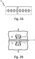
- FIGS. 2A-2B are schematic drawings of recessed undercuts on two polymer components creating a mechanical lock bond.
- recessed feature 26 is present on both first polymer component 22 and second polymer component 24.
- Recessed features 26 create a mechanical lock between polymer components 22, 24, and are both filled with adhesive 27. When adhesive 27 is cured, it creates a mechanical lock in conjunction with features 26.
- Undercuts used to create a mechanical lock, such as undercuts 29 in recessed feature 26 can be linear or curved, and may follow a planar or non-planar surface. Additionally, a radius feature on external edges or internal corners of undercut grooves can be created to further mitigate stress concentrations on adhesive materials and polymer components.
- Mating features creating mechanical locks can include recessed features, such as grooves and void spaces in conjunction with protruding features, such as pins and blades.
- recessed features such as grooves and void spaces in conjunction with protruding features, such as pins and blades.
- protruding features such as pins and blades.
- FIGS. 3-5 Various embodiments of these undercut features are illustrated in FIGS. 3-5 .
- FIGS. 3A-3C are schematic drawings of a mechanical lock in the polymer article 30 bond between first polymer component 32 and second polymer component 34, in a pinhole configuration.
- First polymer component 32 contains a mating feature in the form of void spaces 36.
- Second polymer component 34 contains a different mating feature in the form of protruding pins 38 which are fitted to void spaces 36 on first polymer component 32.
- Void spaces 36 and pins 38 are created through additive manufacturing or 3-D printing.
- Both pins 38 and void spaces 36 contain complex wall undercut structures.
- the complex wall undercut structures can be linear or curved grooves, spiral patterns, corrugated walls, dovetail shaping, or helical threads.
- the array of pins 38 fitted in void spaces 36 creates a mechanical lock between an adhesive and polymer components 32, 34.
- FIGS. 4A-C are schematic drawings of a mechanical lock bond in article 40 between two polymer components in a recessed blades configuration.
- First polymer component 42 contains recessed blades 46.
- Second polymer component 44 contains raised blades 48 which are fitted to recessed blades 46 on first polymer component 42.
- the mating features, recessed blades 46 and raised blades 48, are created through additive manufacturing or 3-D printing.
- Both raised blades 48 and recessed blades 46 contain complex wall undercut structures.
- a concentric pattern on recessed blades 46 on first polymer component 42 creates a mechanical lock with raised blades 48 on second polymer component 44.
- FIGS. 5A-C are schematic drawings of a mechanical lock bond between two polymer components in a ring-blade configuration.
- Article 50 shows a joint between two polymer components.
- First polymer component 52 contains a mating feature of recessed rings 56.
- Second polymer component 54 contains a mating feature of raised rings 58 that fit with recessed rings 56 on first polymer component 52.
- Recessed rings 56 and raised rings 58 are created through additive manufacturing or 3-D printing.
- Both raised rings 58 and recessed rings 56 contain complex wall undercut structures. The extended surface area of the complex wall undercut structures helps an adhesive create a strong bond between both first polymer component 52 and second polymer component 54.
- the combination of an adhesive with mating features 56, 58 and undercuts creates a mechanical lock for polymer components 52, 54.
- the proposed bond creates an enhanced joint between polymer components with both a mechanical lock and adhesive for overall durability and longer lifespan. This allows for significant improvement in strength and reliability of adhesive bond joints between difficult to bond materials, such as low energy polymer components.
- this feature reduces sensitivity of polymer component joints to contamination by reliance on mechanical locking in addition to adhesives.
- mechanical locking in addition to adhesives.
- the mechanical locking undercut features further simplify assembly accuracy, due to the self-locating nature of matching undercut features on polymer component surfaces. This is particularly true when a protruding feature is matched with a recessed feature. Overall, this allows for strong, reliable, large polymer structures comprised of multiple small components.
- FIG. 6 is a schematic drawing of a peel-resistant edge bond between two polymer components.
- Article 60 includes first polymer component 62 and second polymer component 64, joined by bond 61.
- Bond 61 includes adhesive gap 65 filled with adhesive 67, and features 66. Bond 61 mechanically locks, working in conjunction with adhesive 67 to maintain a connection between polymer components 62, 64.
- article 60 contains bumper region 70.
- Bumper region 70 includes edge protective bumper 72, buried taper 74, and tapered edges 76.
- edges of the polymer components "peel" away from each other.
- Bumper region 70 is designed to prevent edge peel.
- Tapered edges 76 prevent some peel by avoiding the use of sharp edges on components 62, 64; and bumper 72 further protects polymer components 62, 64 from peeling away from adhesive gap 65 by providing a physical barrier.
- Buried taper feature 74 reduces stress on bond 61.
- article 60 contains the mechanical lock undercut feature that allows for a strong bond and protected edge.
- the proposed polymer surface geometry allows for mechanical locking of polymer components in conjunction with an adhesive bond. This configuration strengthens bonding between polymer components, increases lifespan of bonds, and allows polymer component joints to withstand tension, shear, torsion or edge peel forces.
- a method of bonding polymer components includes additively manufacturing a first polymer component having a first mating feature, additively manufacturing a second polymer component having a second mating feature, the second mating feature designed to fit with the first mating feature, and joining the first and second polymer components with an adhesive to form a mechanical lock wherein the mechanical lock comprises the first mating feature, the second mating feature and the adhesive.
- the method of the preceding paragraph can optionally include, additionally and/or alternatively, any one or more of the following features, configurations and/or additional components:
- the method includes additively manufacturing an undercut wall structure on the first mating feature.
- the method includes additively manufacturing an undercut wall structure on the second mating feature.
- Additively manufacturing a first polymer component having a first mating feature comprises additively manufacturing a recess into the first polymer component.
- Additively manufacturing a second polymer component having a second mating feature comprises additively manufacturing a protrusion onto the second polymer component, the protrusion configured to mate with the first mating feature.
- Additively manufacturing a second polymer component having a second mating feature comprises additively manufacturing a recess into the second polymer component.
- Additively manufacturing a first polymer component having a first mating feature comprises additively manufacturing a void space; and wherein additively manufacturing a second polymer component having a second mating feature comprises additively manufacturing a projection, the projection complementing the void space.
- Additively manufacturing a first polymer component having a first mating feature comprises additively manufacturing a recessed blade; and wherein additively manufacturing a second polymer component having a second mating feature comprises additively manufacturing a raised blade, the raised blade fitted to the recessed blade.
- Additively manufacturing a first polymer component having a first mating feature comprises additively manufacturing a recessed ring; and wherein additively manufacturing a second polymer component having a second mating feature comprises additively manufacturing a raised ring, the raised ring fitted to the recessed ring.
- a polymer article includes a first polymer component having a first surface and an edge, the first polymer component comprising a first mating feature on the first surface, a second polymer component having a second surface and an edge, the second polymer component comprising a second mating feature on the second surface, and a mechanical lock between the first polymer component and the second polymer component including.
- the mechanical lock includes the first mating feature fitted to the second mating feature by an adhesive.
- the polymer article of the preceding paragraph can optionally include, additionally and/or alternatively, any one or more of the following features, configurations and/or additional components:
- the polymer article includes an undercut wall structure configured to increase the surface area of the first mating feature.
- the first mating feature comprises a recess.
- the second mating feature comprises a protrusion configured to mate with the first mating feature.
- the second mating feature comprises a recess.
- the first mating feature comprises a void space and the second mating feature comprises a protrusion.
- the first mating feature comprises a recessed blade and the second mating feature comprises a raised blade.
- the first mating feature comprises a recessed ring and the second mating feature comprises a raised ring.
- the polymer article includes a bumper connected to the edge of the first polymer component and connected to the edge of the second polymer component.
- the edges of the first and second polymer components are tapered.
- the polymer article includes a first buried taper adjacent to the edge of the first polymer component, and a second buried taper adjacent to the edge of the second polymer component.
Landscapes
- Engineering & Computer Science (AREA)
- Mechanical Engineering (AREA)
- Chemical & Material Sciences (AREA)
- Chemical Kinetics & Catalysis (AREA)
- General Chemical & Material Sciences (AREA)
- Lining Or Joining Of Plastics Or The Like (AREA)
Abstract
Description
- The disclosure relates generally to additive manufacturing techniques, and specifically to bonding two or more polymer components.
- In additive manufacturing processes, creating a strong bond between two polymer components can be problematic due to relatively low surface energies of the polymer components. Industry standards employ methods such as solvents, diffusion techniques, heat staking, cross-linking, and ultrasonic welding. However, these techniques are both expensive and time consuming.
- Instead, many methods employ simple adhesive methods, such as epoxy, olefin, or methacrylate. Adhesive-based bonds between polymer components, while inexpensive, have marginal adhesion and are generally low strength bonds. Adhesive-based polymer bonds can be aggravated by surface contaminates such as grease, processing debris, dirt, or oil. Thus, adhesive-based bonds between polymer components are generally weak and can weaken over time.
- Some techniques use surface preparation, such as plasma etching, exposure to an open flame, or acid etching. These surface preparation techniques can help to some degree, but these processes further add cost to the method and will degrade over time, resulting in a weak bond between polymer components. There is no simple, affordable method that creates improved performance of adhesively bonded polymer joints.
- A method of bonding polymer components includes additively manufacturing a first polymer component having a first mating feature, additively manufacturing a second polymer component having a second mating feature, the second mating feature designed to fit with the first mating feature, and joining the first and second polymer components with an adhesive to form a a mechanical lock wherein the mechanical lock comprises the first mating feature, the second mating feature and the adhesive.
- A polymer article includes a first polymer component having a first surface and an edge, the first polymer component comprising a first mating feature on the first surface, a second polymer component having a second surface and an edge, the second polymer component comprising a second mating feature on the second surface, and a mechanical lock between the first polymer component and the second polymer component including. The mechanical lock includes the first mating feature fitted to the second mating feature by an adhesive.
-
-
FIGS. 1A-1B are schematic drawings of a mechanical lock bond between two polymer components in different embodiments. -
FIGS. 2A-2B are schematic drawings of recessed undercuts on two polymer components creating a mechanical lock bond. -
FIGS. 3A-3C are schematic drawings of a mechanical lock bond between two polymer components in a pinhole configuration. -
FIGS. 4A-C are schematic drawings of a mechanical lock bond between two polymer components in a recessed blades configuration. -
FIGS. 5A-C are schematic drawings of a mechanical lock bond between two polymer components in a ring-blade configuration. -
FIG. 6 is a schematic drawing of a peel-resistant edge bond between two polymer components. - Adhesive-based bonds between polymer components can be strengthened through mechanical locks. Appropriately shape features on surfaces of the polymer components can enhance the bond strength and integrity by creating mechanical locks that work in conjunction with an adhesive. These surface shapes can also distribute stressors on edges of polymer components that would normally cause peeling at a bond site.
-
FIGS. 1A-1B are schematic drawings of a mechanical lock bond between two polymer components in different embodiments. Inarticle 10A ofFIG. 1A ,bond 11 connectsfirst polymer component 12 andsecond polymer component 14.Polymer components -
Bond 11 inFIG. 1A is an adhesive bond enhanced by a mechanical lock.Bond 11 includesadhesive gap 15 between two mating features:insert feature 16 and protrudingfeature 18.Adhesive gap 15 is filled by adhesive 17.Adhesive 17 is an epoxy, olefin, or methacrylate used to filladhesive gap 15 betweenfirst polymer component 12 andsecond polymer component 14.Adhesive 17 can be a neat adhesive (without a filler material) or a reinforced adhesive (such as an epoxy with a filler material to enhance adhesive properties). -
Polymer components components feature 18 andinsert feature 16 create a mechanical lock inbond 11 that works in conjunction with adhesive 17 to hold togetherpolymer components feature 18 andinsert feature 16 have undercutfeatures 19 which provide more stability to the mechanical lock. -
Undercut features 19 can have a variety of shapes, such as corrugated walls, dovetail shapes, or helical threads. InFIGS. 1A-1B , features 16, 18, are nested mating features with undercut walls that create a mechanical lock. The use ofinsert feature 16 allowsbond 11 to benefit from a mechanical lock in addition to an adhesive when joiningpolymer components Features polymer components FIG. 1B shows bond 11, that is similar tobond 11 inFIG. 1A , but increases the number of grooves inundercut feature 19 oninsert feature 16. - When features grown with additive manufacturing, such as
features components components - The mechanical lock of
FIGS. 1A-1B is made through an additive manufacturing or 3-D printing technique. As polymer components such as 12 and 14 are created through normal additive manufacturing processes, undercut features can be directly grown on polymer components. -
FIGS. 2A-2B are schematic drawings of recessed undercuts on two polymer components creating a mechanical lock bond. Inarticle 20 ofFIGS. 2A-2B , recessedfeature 26 is present on bothfirst polymer component 22 andsecond polymer component 24. Recessed features 26 create a mechanical lock betweenpolymer components undercuts 29 in recessedfeature 26, can be linear or curved, and may follow a planar or non-planar surface. Additionally, a radius feature on external edges or internal corners of undercut grooves can be created to further mitigate stress concentrations on adhesive materials and polymer components. - Mating features creating mechanical locks can include recessed features, such as grooves and void spaces in conjunction with protruding features, such as pins and blades. Various embodiments of these undercut features are illustrated in
FIGS. 3-5 . -
FIGS. 3A-3C are schematic drawings of a mechanical lock in thepolymer article 30 bond betweenfirst polymer component 32 andsecond polymer component 34, in a pinhole configuration.First polymer component 32 contains a mating feature in the form ofvoid spaces 36.Second polymer component 34 contains a different mating feature in the form of protrudingpins 38 which are fitted to voidspaces 36 onfirst polymer component 32.Void spaces 36 and pins 38 are created through additive manufacturing or 3-D printing. Both pins 38 andvoid spaces 36, contain complex wall undercut structures. The complex wall undercut structures can be linear or curved grooves, spiral patterns, corrugated walls, dovetail shaping, or helical threads. The array ofpins 38 fitted invoid spaces 36, as shown inFIG. 3C , creates a mechanical lock between an adhesive andpolymer components -
FIGS. 4A-C are schematic drawings of a mechanical lock bond inarticle 40 between two polymer components in a recessed blades configuration.First polymer component 42 contains recessedblades 46.Second polymer component 44 contains raisedblades 48 which are fitted to recessedblades 46 onfirst polymer component 42. The mating features, recessedblades 46 and raisedblades 48, are created through additive manufacturing or 3-D printing. Both raisedblades 48 and recessedblades 46 contain complex wall undercut structures. In this embodiment, a concentric pattern on recessedblades 46 onfirst polymer component 42 creates a mechanical lock with raisedblades 48 onsecond polymer component 44. -
FIGS. 5A-C are schematic drawings of a mechanical lock bond between two polymer components in a ring-blade configuration.Article 50 shows a joint between two polymer components.First polymer component 52 contains a mating feature of recessed rings 56.Second polymer component 54 contains a mating feature of raisedrings 58 that fit with recessedrings 56 onfirst polymer component 52. Recessed rings 56 and raisedrings 58 are created through additive manufacturing or 3-D printing. Both raisedrings 58 and recessedrings 56 contain complex wall undercut structures. The extended surface area of the complex wall undercut structures helps an adhesive create a strong bond between bothfirst polymer component 52 andsecond polymer component 54. The combination of an adhesive with mating features 56, 58 and undercuts creates a mechanical lock forpolymer components - The proposed bond creates an enhanced joint between polymer components with both a mechanical lock and adhesive for overall durability and longer lifespan. This allows for significant improvement in strength and reliability of adhesive bond joints between difficult to bond materials, such as low energy polymer components.
- Additionally, this feature reduces sensitivity of polymer component joints to contamination by reliance on mechanical locking in addition to adhesives. Thus, if an adhesive is degraded through outside contamination such as oil, debris, or dirt, a mechanical lock still holds polymer components in place.
- The mechanical locking undercut features further simplify assembly accuracy, due to the self-locating nature of matching undercut features on polymer component surfaces. This is particularly true when a protruding feature is matched with a recessed feature. Overall, this allows for strong, reliable, large polymer structures comprised of multiple small components.
-
FIG. 6 is a schematic drawing of a peel-resistant edge bond between two polymer components.Article 60 includesfirst polymer component 62 andsecond polymer component 64, joined bybond 61.Bond 61 includesadhesive gap 65 filled with adhesive 67, and features 66.Bond 61 mechanically locks, working in conjunction with adhesive 67 to maintain a connection betweenpolymer components - Additionally,
article 60 containsbumper region 70.Bumper region 70 includes edgeprotective bumper 72, buriedtaper 74, and tapered edges 76. Typically, when two or more polymer components are connected with an adhesive, edges of the polymer components "peel" away from each other.Bumper region 70 is designed to prevent edge peel. Tapered edges 76 prevent some peel by avoiding the use of sharp edges oncomponents bumper 72 further protectspolymer components adhesive gap 65 by providing a physical barrier. Buriedtaper feature 74 reduces stress onbond 61. Overall,article 60 contains the mechanical lock undercut feature that allows for a strong bond and protected edge. - The proposed polymer surface geometry allows for mechanical locking of polymer components in conjunction with an adhesive bond. This configuration strengthens bonding between polymer components, increases lifespan of bonds, and allows polymer component joints to withstand tension, shear, torsion or edge peel forces.
- The following are non-exclusive descriptions of possible embodiments of the present invention.
- A method of bonding polymer components includes additively manufacturing a first polymer component having a first mating feature, additively manufacturing a second polymer component having a second mating feature, the second mating feature designed to fit with the first mating feature, and joining the first and second polymer components with an adhesive to form a mechanical lock wherein the mechanical lock comprises the first mating feature, the second mating feature and the adhesive.
- The method of the preceding paragraph can optionally include, additionally and/or alternatively, any one or more of the following features, configurations and/or additional components:
The method includes additively manufacturing an undercut wall structure on the first mating feature. - The method includes additively manufacturing an undercut wall structure on the second mating feature.
- Additively manufacturing a first polymer component having a first mating feature comprises additively manufacturing a recess into the first polymer component.
- Additively manufacturing a second polymer component having a second mating feature comprises additively manufacturing a protrusion onto the second polymer component, the protrusion configured to mate with the first mating feature.
- Additively manufacturing a second polymer component having a second mating feature comprises additively manufacturing a recess into the second polymer component.
- Additively manufacturing a first polymer component having a first mating feature comprises additively manufacturing a void space; and wherein additively manufacturing a second polymer component having a second mating feature comprises additively manufacturing a projection, the projection complementing the void space.
- Additively manufacturing a first polymer component having a first mating feature comprises additively manufacturing a recessed blade; and wherein additively manufacturing a second polymer component having a second mating feature comprises additively manufacturing a raised blade, the raised blade fitted to the recessed blade.
- Additively manufacturing a first polymer component having a first mating feature comprises additively manufacturing a recessed ring; and wherein additively manufacturing a second polymer component having a second mating feature comprises additively manufacturing a raised ring, the raised ring fitted to the recessed ring.
- A polymer article includes a first polymer component having a first surface and an edge, the first polymer component comprising a first mating feature on the first surface, a second polymer component having a second surface and an edge, the second polymer component comprising a second mating feature on the second surface, and a mechanical lock between the first polymer component and the second polymer component including. The mechanical lock includes the first mating feature fitted to the second mating feature by an adhesive.
- The polymer article of the preceding paragraph can optionally include, additionally and/or alternatively, any one or more of the following features, configurations and/or additional components:
The polymer article includes an undercut wall structure configured to increase the surface area of the first mating feature. - The first mating feature comprises a recess.
- The second mating feature comprises a protrusion configured to mate with the first mating feature.
- The second mating feature comprises a recess.
- The first mating feature comprises a void space and the second mating feature comprises a protrusion.
- The first mating feature comprises a recessed blade and the second mating feature comprises a raised blade.
- The first mating feature comprises a recessed ring and the second mating feature comprises a raised ring.
- The polymer article includes a bumper connected to the edge of the first polymer component and connected to the edge of the second polymer component.
- The edges of the first and second polymer components are tapered.
- The polymer article includes a first buried taper adjacent to the edge of the first polymer component, and a second buried taper adjacent to the edge of the second polymer component.
- While the invention has been described with reference to an exemplary embodiment(s), it will be understood by those skilled in the art that various changes may be made and equivalents may be substituted for elements thereof without departing from the scope of the invention. In addition, many modifications may be made to adapt a particular situation or material to the teachings of the invention without departing from the essential scope thereof. Therefore, it is intended that the invention not be limited to the particular embodiment(s) disclosed, but that the invention will include all embodiments falling within the scope of the appended claims.
Claims (15)
- A method of bonding polymer components comprises:additively manufacturing a first polymer component having a first mating feature;additively manufacturing a second polymer component having a second mating feature, the second mating feature designed to fit with the first mating feature; andjoining the first and second polymer components with an adhesive to form a mechanical lock wherein the mechanical lock comprises the first mating feature, the second mating feature and the adhesive.
- The method of claim 1, further comprising additively manufacturing an undercut wall structure on the first mating feature,
and / or preferably further comprising additively manufacturing an undercut wall structure on the second mating feature. - The method of claim 1 or 2, wherein additively manufacturing a first polymer component having a first mating feature comprises additively manufacturing a recess into the first polymer component.
- The method of claim 3, wherein additively manufacturing a second polymer component having a second mating feature comprises additively manufacturing a protrusion onto the second polymer component, the protrusion configured to mate with the first mating feature,
or wherein additively manufacturing a second polymer component having a second mating feature comprises additively manufacturing a recess into the second polymer component. - The method of claim 1, wherein additively manufacturing a first polymer component having a first mating feature comprises additively manufacturing a void space; and wherein additively manufacturing a second polymer component having a second mating feature comprises additively manufacturing a projection, the projection complementing the void space.
- The method of claim 1, wherein additively manufacturing a first polymer component having a first mating feature comprises additively manufacturing a recessed blade; and wherein additively manufacturing a second polymer component having a second mating feature comprises additively manufacturing a raised blade, the raised blade fitted to the recessed blade.
- The method of claim 1, wherein additively manufacturing a first polymer component having a first mating feature comprises additively manufacturing a recessed ring; and wherein additively manufacturing a second polymer component having a second mating feature comprises additively manufacturing a raised ring, the raised ring fitted to the recessed ring.
- A polymer article comprises:a first polymer component having a first surface and an edge, the first polymer component comprising a first mating feature on the first surface;a second polymer component having a second surface and an edge, the second polymer component comprising a second mating feature on the second surface; anda mechanical lock comprising the first mating feature fitted to the second mating feature by an adhesive.
- The polymer article of claim 8, further comprising an undercut wall structure configured to increase the surface area of the first mating feature.
- The polymer article of claim 8, wherein the first mating feature comprises a recess.
- The polymer article of claim 10, wherein the second mating feature comprises a protrusion configured to mate with the first mating feature,
or wherein the second mating feature comprises a recess. - The polymer article of claim 8, wherein the first mating feature comprises a void space and the second mating feature comprises a protrusion.
- The polymer article of claim 8, wherein the first mating feature comprises a recessed blade and the second mating feature comprises a raised blade, or
wherein the first mating feature comprises a recessed ring and the second mating feature comprises a raised ring. - The polymer article of any of claims 8 to 13, further comprising a bumper connected to the edge of the first polymer component and connected to the edge of the second polymer component.
- The polymer article of any of claims 8 to 14, wherein the edges of the first and second polymer components are tapered, and preferably further comprising a first buried taper adjacent to the edge of the first polymer component, and a second buried taper adjacent to the edge of the second polymer component.
Applications Claiming Priority (1)
| Application Number | Priority Date | Filing Date | Title |
|---|---|---|---|
| US15/479,401 US10639864B2 (en) | 2017-04-05 | 2017-04-05 | Surface geometry for adhesive bonding of polymer components |
Publications (2)
| Publication Number | Publication Date |
|---|---|
| EP3385076A1 true EP3385076A1 (en) | 2018-10-10 |
| EP3385076B1 EP3385076B1 (en) | 2025-01-08 |
Family
ID=61691748
Family Applications (1)
| Application Number | Title | Priority Date | Filing Date |
|---|---|---|---|
| EP18162516.1A Active EP3385076B1 (en) | 2017-04-05 | 2018-03-19 | Method and product with surface geometry for adhesive bonding of polymer components |
Country Status (2)
| Country | Link |
|---|---|
| US (1) | US10639864B2 (en) |
| EP (1) | EP3385076B1 (en) |
Cited By (4)
| Publication number | Priority date | Publication date | Assignee | Title |
|---|---|---|---|---|
| WO2020097420A1 (en) | 2018-11-08 | 2020-05-14 | Divergent Technologies, Inc. | Systems and methods for adhesive-based part retention features in additively manufactured structures |
| WO2022169568A1 (en) * | 2021-02-07 | 2022-08-11 | The Boeing Company | Three-dimensional structured multi-level interlocking structure and preparation method thereof |
| US11806941B2 (en) | 2020-08-21 | 2023-11-07 | Divergent Technologies, Inc. | Mechanical part retention features for additively manufactured structures |
| US11850804B2 (en) | 2020-07-28 | 2023-12-26 | Divergent Technologies, Inc. | Radiation-enabled retention features for fixtureless assembly of node-based structures |
Families Citing this family (3)
| Publication number | Priority date | Publication date | Assignee | Title |
|---|---|---|---|---|
| US12203328B2 (en) * | 2022-01-20 | 2025-01-21 | Joe Fox | Downhole inductive transmission coupler with nonlinear coil |
| US12015001B2 (en) * | 2022-03-15 | 2024-06-18 | Taiwan Semiconductor Manufacturing Company Ltd. | Bonding structure and method thereof |
| FR3140572A1 (en) * | 2022-10-10 | 2024-04-12 | Safran | Process for manufacturing a part by assembling intermediate parts obtained by additive manufacturing by filament deposition |
Citations (3)
| Publication number | Priority date | Publication date | Assignee | Title |
|---|---|---|---|---|
| US20090085257A1 (en) * | 2007-09-28 | 2009-04-02 | Korea Advanced Institute Of Science And Technology | Method for Producing Three-Dimensional Objects Using Segmental Prototyping |
| US20160272295A1 (en) * | 2015-03-19 | 2016-09-22 | Airbus Operations Gmbh | Connection system, connection arrangement and method |
| EP3162470A1 (en) * | 2015-10-20 | 2017-05-03 | General Electric Company | Repair methods utilizing additively manufacturing for rotor blades and components |
Family Cites Families (6)
| Publication number | Priority date | Publication date | Assignee | Title |
|---|---|---|---|---|
| US6406636B1 (en) | 1999-06-02 | 2002-06-18 | Megasense, Inc. | Methods for wafer to wafer bonding using microstructures |
| US6436502B1 (en) * | 2000-10-26 | 2002-08-20 | Xerox Corporation | Belts having overlapping end sections |
| US6543404B2 (en) * | 2001-04-04 | 2003-04-08 | Dow Global Technologies, Inc. | Adhesively bonded engine intake manifold assembly |
| US7341330B2 (en) | 2005-02-28 | 2008-03-11 | Silverbrook Research Pty Ltd | Substrates adapted for adhesive bonding |
| DE102011078149A1 (en) | 2011-06-27 | 2012-12-27 | Airbus Operations Gmbh | METHOD AND DEVICE FOR JOINING SUPPLEMENTS, AND COMPONENT |
| WO2015006428A1 (en) | 2013-07-09 | 2015-01-15 | United Technologies Corporation | Interlocked plated polymers |
-
2017
- 2017-04-05 US US15/479,401 patent/US10639864B2/en active Active
-
2018
- 2018-03-19 EP EP18162516.1A patent/EP3385076B1/en active Active
Patent Citations (3)
| Publication number | Priority date | Publication date | Assignee | Title |
|---|---|---|---|---|
| US20090085257A1 (en) * | 2007-09-28 | 2009-04-02 | Korea Advanced Institute Of Science And Technology | Method for Producing Three-Dimensional Objects Using Segmental Prototyping |
| US20160272295A1 (en) * | 2015-03-19 | 2016-09-22 | Airbus Operations Gmbh | Connection system, connection arrangement and method |
| EP3162470A1 (en) * | 2015-10-20 | 2017-05-03 | General Electric Company | Repair methods utilizing additively manufacturing for rotor blades and components |
Cited By (7)
| Publication number | Priority date | Publication date | Assignee | Title |
|---|---|---|---|---|
| WO2020097420A1 (en) | 2018-11-08 | 2020-05-14 | Divergent Technologies, Inc. | Systems and methods for adhesive-based part retention features in additively manufactured structures |
| EP3877154A4 (en) * | 2018-11-08 | 2022-09-07 | Divergent Technologies, Inc. | Systems and methods for adhesive-based part retention features in additively manufactured structures |
| US12115583B2 (en) | 2018-11-08 | 2024-10-15 | Divergent Technologies, Inc. | Systems and methods for adhesive-based part retention features in additively manufactured structures |
| US11850804B2 (en) | 2020-07-28 | 2023-12-26 | Divergent Technologies, Inc. | Radiation-enabled retention features for fixtureless assembly of node-based structures |
| US12560191B2 (en) | 2020-07-28 | 2026-02-24 | Divergent Technologies, Inc. | Radiation-enabled retention features for fixtureless assembly of node-based structures |
| US11806941B2 (en) | 2020-08-21 | 2023-11-07 | Divergent Technologies, Inc. | Mechanical part retention features for additively manufactured structures |
| WO2022169568A1 (en) * | 2021-02-07 | 2022-08-11 | The Boeing Company | Three-dimensional structured multi-level interlocking structure and preparation method thereof |
Also Published As
| Publication number | Publication date |
|---|---|
| US20180290423A1 (en) | 2018-10-11 |
| US10639864B2 (en) | 2020-05-05 |
| EP3385076B1 (en) | 2025-01-08 |
Similar Documents
| Publication | Publication Date | Title |
|---|---|---|
| US10639864B2 (en) | Surface geometry for adhesive bonding of polymer components | |
| US10288584B2 (en) | Method for locating machining position in repair material, and repairing method | |
| CN100355551C (en) | Interlocking tooth engagement for components of fiber composite laminates | |
| JP2011116127A (en) | Method for joining metal and plastic workpieces | |
| KR20100114919A (en) | Variable grip blind rivet | |
| JP7104641B2 (en) | Synthetic segments, rings and buried structures | |
| WO2015049898A1 (en) | Joint, and aircraft structure | |
| CN106989263A (en) | Systems and processes for robustly joining workpieces using bumps and adhesives | |
| AU2012297304A1 (en) | Armouring element for unbonded flexible pipe | |
| CN107667000A (en) | Composite welding of thermoplastics | |
| JP4714040B2 (en) | FRP junction structure and manufacturing method thereof | |
| US10550871B2 (en) | Method for producing a component connection and component connection | |
| JP5446744B2 (en) | Car body joining structure and assembling method of car body joining structure | |
| KR20190114362A (en) | PHC pile having screw combining type connecting module | |
| CN110341376A (en) | Wheel for vehicle hub | |
| KR101924574B1 (en) | Connecting method of shaft with yoke using magnetic pulse effect and shaft assembly connected by the method | |
| JP4577115B2 (en) | Resin parts and joining method of resin parts | |
| KR200494224Y1 (en) | Lifting lug on Leg of Floating Structure | |
| JP2005319793A (en) | Composite component | |
| JP2019167063A (en) | Vehicle wheel | |
| JP4781088B2 (en) | Beam through hole reinforcement bracket, beam through hole reinforcement structure | |
| KR20160082580A (en) | Adhering structure and method of different kinds of materials | |
| JP6880959B2 (en) | Joined body and joining method | |
| FI125385B (en) | Connecting elements and method for joining wooden structures | |
| KR20150047160A (en) | T-butt welded joint |
Legal Events
| Date | Code | Title | Description |
|---|---|---|---|
| PUAI | Public reference made under article 153(3) epc to a published international application that has entered the european phase |
Free format text: ORIGINAL CODE: 0009012 |
|
| STAA | Information on the status of an ep patent application or granted ep patent |
Free format text: STATUS: THE APPLICATION HAS BEEN PUBLISHED |
|
| AK | Designated contracting states |
Kind code of ref document: A1 Designated state(s): AL AT BE BG CH CY CZ DE DK EE ES FI FR GB GR HR HU IE IS IT LI LT LU LV MC MK MT NL NO PL PT RO RS SE SI SK SM TR |
|
| AX | Request for extension of the european patent |
Extension state: BA ME |
|
| STAA | Information on the status of an ep patent application or granted ep patent |
Free format text: STATUS: REQUEST FOR EXAMINATION WAS MADE |
|
| 17P | Request for examination filed |
Effective date: 20190409 |
|
| RBV | Designated contracting states (corrected) |
Designated state(s): AL AT BE BG CH CY CZ DE DK EE ES FI FR GB GR HR HU IE IS IT LI LT LU LV MC MK MT NL NO PL PT RO RS SE SI SK SM TR |
|
| STAA | Information on the status of an ep patent application or granted ep patent |
Free format text: STATUS: EXAMINATION IS IN PROGRESS |
|
| 17Q | First examination report despatched |
Effective date: 20200827 |
|
| RAP1 | Party data changed (applicant data changed or rights of an application transferred) |
Owner name: RAYTHEON TECHNOLOGIES CORPORATION |
|
| RAP3 | Party data changed (applicant data changed or rights of an application transferred) |
Owner name: RTX CORPORATION |
|
| GRAP | Despatch of communication of intention to grant a patent |
Free format text: ORIGINAL CODE: EPIDOSNIGR1 |
|
| STAA | Information on the status of an ep patent application or granted ep patent |
Free format text: STATUS: GRANT OF PATENT IS INTENDED |
|
| INTG | Intention to grant announced |
Effective date: 20240729 |
|
| GRAS | Grant fee paid |
Free format text: ORIGINAL CODE: EPIDOSNIGR3 |
|
| GRAA | (expected) grant |
Free format text: ORIGINAL CODE: 0009210 |
|
| STAA | Information on the status of an ep patent application or granted ep patent |
Free format text: STATUS: THE PATENT HAS BEEN GRANTED |
|
| AK | Designated contracting states |
Kind code of ref document: B1 Designated state(s): AL AT BE BG CH CY CZ DE DK EE ES FI FR GB GR HR HU IE IS IT LI LT LU LV MC MK MT NL NO PL PT RO RS SE SI SK SM TR |
|
| REG | Reference to a national code |
Ref country code: GB Ref legal event code: FG4D |
|
| RIN1 | Information on inventor provided before grant (corrected) |
Inventor name: TWELVES, WENDELL V., JR. Inventor name: BUTCHER, EVAN |
|
| REG | Reference to a national code |
Ref country code: CH Ref legal event code: EP |
|
| REG | Reference to a national code |
Ref country code: DE Ref legal event code: R096 Ref document number: 602018078302 Country of ref document: DE |
|
| REG | Reference to a national code |
Ref country code: IE Ref legal event code: FG4D |
|
| REG | Reference to a national code |
Ref country code: LT Ref legal event code: MG9D |
|
| REG | Reference to a national code |
Ref country code: NL Ref legal event code: MP Effective date: 20250108 |
|
| REG | Reference to a national code |
Ref country code: AT Ref legal event code: MK05 Ref document number: 1758084 Country of ref document: AT Kind code of ref document: T Effective date: 20250108 |
|
| PG25 | Lapsed in a contracting state [announced via postgrant information from national office to epo] |
Ref country code: NL Free format text: LAPSE BECAUSE OF FAILURE TO SUBMIT A TRANSLATION OF THE DESCRIPTION OR TO PAY THE FEE WITHIN THE PRESCRIBED TIME-LIMIT Effective date: 20250108 |
|
| PG25 | Lapsed in a contracting state [announced via postgrant information from national office to epo] |
Ref country code: RS Free format text: LAPSE BECAUSE OF FAILURE TO SUBMIT A TRANSLATION OF THE DESCRIPTION OR TO PAY THE FEE WITHIN THE PRESCRIBED TIME-LIMIT Effective date: 20250408 |
|
| PG25 | Lapsed in a contracting state [announced via postgrant information from national office to epo] |
Ref country code: FI Free format text: LAPSE BECAUSE OF FAILURE TO SUBMIT A TRANSLATION OF THE DESCRIPTION OR TO PAY THE FEE WITHIN THE PRESCRIBED TIME-LIMIT Effective date: 20250108 |
|
| PG25 | Lapsed in a contracting state [announced via postgrant information from national office to epo] |
Ref country code: PL Free format text: LAPSE BECAUSE OF FAILURE TO SUBMIT A TRANSLATION OF THE DESCRIPTION OR TO PAY THE FEE WITHIN THE PRESCRIBED TIME-LIMIT Effective date: 20250108 |
|
| PG25 | Lapsed in a contracting state [announced via postgrant information from national office to epo] |
Ref country code: ES Free format text: LAPSE BECAUSE OF FAILURE TO SUBMIT A TRANSLATION OF THE DESCRIPTION OR TO PAY THE FEE WITHIN THE PRESCRIBED TIME-LIMIT Effective date: 20250108 |
|
| PG25 | Lapsed in a contracting state [announced via postgrant information from national office to epo] |
Ref country code: NO Free format text: LAPSE BECAUSE OF FAILURE TO SUBMIT A TRANSLATION OF THE DESCRIPTION OR TO PAY THE FEE WITHIN THE PRESCRIBED TIME-LIMIT Effective date: 20250408 Ref country code: IS Free format text: LAPSE BECAUSE OF FAILURE TO SUBMIT A TRANSLATION OF THE DESCRIPTION OR TO PAY THE FEE WITHIN THE PRESCRIBED TIME-LIMIT Effective date: 20250508 |
|
| PG25 | Lapsed in a contracting state [announced via postgrant information from national office to epo] |
Ref country code: HR Free format text: LAPSE BECAUSE OF FAILURE TO SUBMIT A TRANSLATION OF THE DESCRIPTION OR TO PAY THE FEE WITHIN THE PRESCRIBED TIME-LIMIT Effective date: 20250108 |
|
| PG25 | Lapsed in a contracting state [announced via postgrant information from national office to epo] |
Ref country code: LV Free format text: LAPSE BECAUSE OF FAILURE TO SUBMIT A TRANSLATION OF THE DESCRIPTION OR TO PAY THE FEE WITHIN THE PRESCRIBED TIME-LIMIT Effective date: 20250108 Ref country code: PT Free format text: LAPSE BECAUSE OF FAILURE TO SUBMIT A TRANSLATION OF THE DESCRIPTION OR TO PAY THE FEE WITHIN THE PRESCRIBED TIME-LIMIT Effective date: 20250508 |
|
| PG25 | Lapsed in a contracting state [announced via postgrant information from national office to epo] |
Ref country code: BG Free format text: LAPSE BECAUSE OF FAILURE TO SUBMIT A TRANSLATION OF THE DESCRIPTION OR TO PAY THE FEE WITHIN THE PRESCRIBED TIME-LIMIT Effective date: 20250108 Ref country code: GR Free format text: LAPSE BECAUSE OF FAILURE TO SUBMIT A TRANSLATION OF THE DESCRIPTION OR TO PAY THE FEE WITHIN THE PRESCRIBED TIME-LIMIT Effective date: 20250409 |
|
| PG25 | Lapsed in a contracting state [announced via postgrant information from national office to epo] |
Ref country code: AT Free format text: LAPSE BECAUSE OF FAILURE TO SUBMIT A TRANSLATION OF THE DESCRIPTION OR TO PAY THE FEE WITHIN THE PRESCRIBED TIME-LIMIT Effective date: 20250108 |
|
| PG25 | Lapsed in a contracting state [announced via postgrant information from national office to epo] |
Ref country code: SE Free format text: LAPSE BECAUSE OF FAILURE TO SUBMIT A TRANSLATION OF THE DESCRIPTION OR TO PAY THE FEE WITHIN THE PRESCRIBED TIME-LIMIT Effective date: 20250108 |
|
| PG25 | Lapsed in a contracting state [announced via postgrant information from national office to epo] |
Ref country code: SM Free format text: LAPSE BECAUSE OF FAILURE TO SUBMIT A TRANSLATION OF THE DESCRIPTION OR TO PAY THE FEE WITHIN THE PRESCRIBED TIME-LIMIT Effective date: 20250108 |
|
| REG | Reference to a national code |
Ref country code: DE Ref legal event code: R097 Ref document number: 602018078302 Country of ref document: DE |
|
| PG25 | Lapsed in a contracting state [announced via postgrant information from national office to epo] |
Ref country code: DK Free format text: LAPSE BECAUSE OF FAILURE TO SUBMIT A TRANSLATION OF THE DESCRIPTION OR TO PAY THE FEE WITHIN THE PRESCRIBED TIME-LIMIT Effective date: 20250108 |
|
| PG25 | Lapsed in a contracting state [announced via postgrant information from national office to epo] |
Ref country code: MC Free format text: LAPSE BECAUSE OF FAILURE TO SUBMIT A TRANSLATION OF THE DESCRIPTION OR TO PAY THE FEE WITHIN THE PRESCRIBED TIME-LIMIT Effective date: 20250108 |
|
| PG25 | Lapsed in a contracting state [announced via postgrant information from national office to epo] |
Ref country code: CZ Free format text: LAPSE BECAUSE OF FAILURE TO SUBMIT A TRANSLATION OF THE DESCRIPTION OR TO PAY THE FEE WITHIN THE PRESCRIBED TIME-LIMIT Effective date: 20250108 Ref country code: EE Free format text: LAPSE BECAUSE OF FAILURE TO SUBMIT A TRANSLATION OF THE DESCRIPTION OR TO PAY THE FEE WITHIN THE PRESCRIBED TIME-LIMIT Effective date: 20250108 |
|
| REG | Reference to a national code |
Ref country code: CH Ref legal event code: H13 Free format text: ST27 STATUS EVENT CODE: U-0-0-H10-H13 (AS PROVIDED BY THE NATIONAL OFFICE) Effective date: 20251023 |
|
| PG25 | Lapsed in a contracting state [announced via postgrant information from national office to epo] |
Ref country code: RO Free format text: LAPSE BECAUSE OF FAILURE TO SUBMIT A TRANSLATION OF THE DESCRIPTION OR TO PAY THE FEE WITHIN THE PRESCRIBED TIME-LIMIT Effective date: 20250108 |
|
| PG25 | Lapsed in a contracting state [announced via postgrant information from national office to epo] |
Ref country code: SK Free format text: LAPSE BECAUSE OF FAILURE TO SUBMIT A TRANSLATION OF THE DESCRIPTION OR TO PAY THE FEE WITHIN THE PRESCRIBED TIME-LIMIT Effective date: 20250108 |
|
| PLBE | No opposition filed within time limit |
Free format text: ORIGINAL CODE: 0009261 |
|
| STAA | Information on the status of an ep patent application or granted ep patent |
Free format text: STATUS: NO OPPOSITION FILED WITHIN TIME LIMIT |
|
| PG25 | Lapsed in a contracting state [announced via postgrant information from national office to epo] |
Ref country code: LU Free format text: LAPSE BECAUSE OF NON-PAYMENT OF DUE FEES Effective date: 20250319 |
|
| REG | Reference to a national code |
Ref country code: BE Ref legal event code: MM Effective date: 20250331 |
|
| 26N | No opposition filed |
Effective date: 20251009 |
|
| PG25 | Lapsed in a contracting state [announced via postgrant information from national office to epo] |
Ref country code: IT Free format text: LAPSE BECAUSE OF NON-PAYMENT OF DUE FEES Effective date: 20250319 |
|
| PG25 | Lapsed in a contracting state [announced via postgrant information from national office to epo] |
Ref country code: BE Free format text: LAPSE BECAUSE OF NON-PAYMENT OF DUE FEES Effective date: 20250331 |
|
| PG25 | Lapsed in a contracting state [announced via postgrant information from national office to epo] |
Ref country code: CH Free format text: LAPSE BECAUSE OF NON-PAYMENT OF DUE FEES Effective date: 20250331 |
|
| PG25 | Lapsed in a contracting state [announced via postgrant information from national office to epo] |
Ref country code: IE Free format text: LAPSE BECAUSE OF NON-PAYMENT OF DUE FEES Effective date: 20250319 |
|
| PGFP | Annual fee paid to national office [announced via postgrant information from national office to epo] |
Ref country code: GB Payment date: 20260219 Year of fee payment: 9 |
|
| PGFP | Annual fee paid to national office [announced via postgrant information from national office to epo] |
Ref country code: DE Payment date: 20260219 Year of fee payment: 9 |
|
| PGFP | Annual fee paid to national office [announced via postgrant information from national office to epo] |
Ref country code: FR Payment date: 20260219 Year of fee payment: 9 |