EP3385060A1 - Powder material, method for manufacturing three-dimensional modeled object, and three-dimensional-modeling device - Google Patents
Powder material, method for manufacturing three-dimensional modeled object, and three-dimensional-modeling device Download PDFInfo
- Publication number
- EP3385060A1 EP3385060A1 EP16870285.0A EP16870285A EP3385060A1 EP 3385060 A1 EP3385060 A1 EP 3385060A1 EP 16870285 A EP16870285 A EP 16870285A EP 3385060 A1 EP3385060 A1 EP 3385060A1
- Authority
- EP
- European Patent Office
- Prior art keywords
- resin
- temperature
- powder
- thin layer
- powder material
- Prior art date
- Legal status (The legal status is an assumption and is not a legal conclusion. Google has not performed a legal analysis and makes no representation as to the accuracy of the status listed.)
- Granted
Links
Images


Classifications
-
- B—PERFORMING OPERATIONS; TRANSPORTING
- B29—WORKING OF PLASTICS; WORKING OF SUBSTANCES IN A PLASTIC STATE IN GENERAL
- B29C—SHAPING OR JOINING OF PLASTICS; SHAPING OF MATERIAL IN A PLASTIC STATE, NOT OTHERWISE PROVIDED FOR; AFTER-TREATMENT OF THE SHAPED PRODUCTS, e.g. REPAIRING
- B29C64/00—Additive manufacturing, i.e. manufacturing of three-dimensional [3D] objects by additive deposition, additive agglomeration or additive layering, e.g. by 3D printing, stereolithography or selective laser sintering
- B29C64/10—Processes of additive manufacturing
- B29C64/141—Processes of additive manufacturing using only solid materials
- B29C64/153—Processes of additive manufacturing using only solid materials using layers of powder being selectively joined, e.g. by selective laser sintering or melting
-
- B—PERFORMING OPERATIONS; TRANSPORTING
- B29—WORKING OF PLASTICS; WORKING OF SUBSTANCES IN A PLASTIC STATE IN GENERAL
- B29C—SHAPING OR JOINING OF PLASTICS; SHAPING OF MATERIAL IN A PLASTIC STATE, NOT OTHERWISE PROVIDED FOR; AFTER-TREATMENT OF THE SHAPED PRODUCTS, e.g. REPAIRING
- B29C64/00—Additive manufacturing, i.e. manufacturing of three-dimensional [3D] objects by additive deposition, additive agglomeration or additive layering, e.g. by 3D printing, stereolithography or selective laser sintering
- B29C64/30—Auxiliary operations or equipment
- B29C64/386—Data acquisition or data processing for additive manufacturing
- B29C64/393—Data acquisition or data processing for additive manufacturing for controlling or regulating additive manufacturing processes
-
- B—PERFORMING OPERATIONS; TRANSPORTING
- B33—ADDITIVE MANUFACTURING TECHNOLOGY
- B33Y—ADDITIVE MANUFACTURING, i.e. MANUFACTURING OF THREE-DIMENSIONAL [3D] OBJECTS BY ADDITIVE DEPOSITION, ADDITIVE AGGLOMERATION OR ADDITIVE LAYERING, e.g. BY 3D PRINTING, STEREOLITHOGRAPHY OR SELECTIVE LASER SINTERING
- B33Y10/00—Processes of additive manufacturing
-
- B—PERFORMING OPERATIONS; TRANSPORTING
- B33—ADDITIVE MANUFACTURING TECHNOLOGY
- B33Y—ADDITIVE MANUFACTURING, i.e. MANUFACTURING OF THREE-DIMENSIONAL [3D] OBJECTS BY ADDITIVE DEPOSITION, ADDITIVE AGGLOMERATION OR ADDITIVE LAYERING, e.g. BY 3D PRINTING, STEREOLITHOGRAPHY OR SELECTIVE LASER SINTERING
- B33Y30/00—Apparatus for additive manufacturing; Details thereof or accessories therefor
-
- B—PERFORMING OPERATIONS; TRANSPORTING
- B33—ADDITIVE MANUFACTURING TECHNOLOGY
- B33Y—ADDITIVE MANUFACTURING, i.e. MANUFACTURING OF THREE-DIMENSIONAL [3D] OBJECTS BY ADDITIVE DEPOSITION, ADDITIVE AGGLOMERATION OR ADDITIVE LAYERING, e.g. BY 3D PRINTING, STEREOLITHOGRAPHY OR SELECTIVE LASER SINTERING
- B33Y50/00—Data acquisition or data processing for additive manufacturing
- B33Y50/02—Data acquisition or data processing for additive manufacturing for controlling or regulating additive manufacturing processes
-
- B—PERFORMING OPERATIONS; TRANSPORTING
- B33—ADDITIVE MANUFACTURING TECHNOLOGY
- B33Y—ADDITIVE MANUFACTURING, i.e. MANUFACTURING OF THREE-DIMENSIONAL [3D] OBJECTS BY ADDITIVE DEPOSITION, ADDITIVE AGGLOMERATION OR ADDITIVE LAYERING, e.g. BY 3D PRINTING, STEREOLITHOGRAPHY OR SELECTIVE LASER SINTERING
- B33Y70/00—Materials specially adapted for additive manufacturing
-
- C—CHEMISTRY; METALLURGY
- C08—ORGANIC MACROMOLECULAR COMPOUNDS; THEIR PREPARATION OR CHEMICAL WORKING-UP; COMPOSITIONS BASED THEREON
- C08L—COMPOSITIONS OF MACROMOLECULAR COMPOUNDS
- C08L23/00—Compositions of homopolymers or copolymers of unsaturated aliphatic hydrocarbons having only one carbon-to-carbon double bond; Compositions of derivatives of such polymers
- C08L23/02—Compositions of homopolymers or copolymers of unsaturated aliphatic hydrocarbons having only one carbon-to-carbon double bond; Compositions of derivatives of such polymers not modified by chemical after-treatment
- C08L23/04—Homopolymers or copolymers of ethene
- C08L23/06—Polyethylene
-
- C—CHEMISTRY; METALLURGY
- C08—ORGANIC MACROMOLECULAR COMPOUNDS; THEIR PREPARATION OR CHEMICAL WORKING-UP; COMPOSITIONS BASED THEREON
- C08L—COMPOSITIONS OF MACROMOLECULAR COMPOUNDS
- C08L23/00—Compositions of homopolymers or copolymers of unsaturated aliphatic hydrocarbons having only one carbon-to-carbon double bond; Compositions of derivatives of such polymers
- C08L23/02—Compositions of homopolymers or copolymers of unsaturated aliphatic hydrocarbons having only one carbon-to-carbon double bond; Compositions of derivatives of such polymers not modified by chemical after-treatment
- C08L23/10—Homopolymers or copolymers of propene
- C08L23/12—Polypropene
-
- C—CHEMISTRY; METALLURGY
- C08—ORGANIC MACROMOLECULAR COMPOUNDS; THEIR PREPARATION OR CHEMICAL WORKING-UP; COMPOSITIONS BASED THEREON
- C08L—COMPOSITIONS OF MACROMOLECULAR COMPOUNDS
- C08L25/00—Compositions of, homopolymers or copolymers of compounds having one or more unsaturated aliphatic radicals, each having only one carbon-to-carbon double bond, and at least one being terminated by an aromatic carbocyclic ring; Compositions of derivatives of such polymers
- C08L25/02—Homopolymers or copolymers of hydrocarbons
- C08L25/04—Homopolymers or copolymers of styrene
- C08L25/06—Polystyrene
-
- C—CHEMISTRY; METALLURGY
- C08—ORGANIC MACROMOLECULAR COMPOUNDS; THEIR PREPARATION OR CHEMICAL WORKING-UP; COMPOSITIONS BASED THEREON
- C08L—COMPOSITIONS OF MACROMOLECULAR COMPOUNDS
- C08L67/00—Compositions of polyesters obtained by reactions forming a carboxylic ester link in the main chain; Compositions of derivatives of such polymers
- C08L67/02—Polyesters derived from dicarboxylic acids and dihydroxy compounds
-
- C—CHEMISTRY; METALLURGY
- C08—ORGANIC MACROMOLECULAR COMPOUNDS; THEIR PREPARATION OR CHEMICAL WORKING-UP; COMPOSITIONS BASED THEREON
- C08L—COMPOSITIONS OF MACROMOLECULAR COMPOUNDS
- C08L69/00—Compositions of polycarbonates; Compositions of derivatives of polycarbonates
-
- C—CHEMISTRY; METALLURGY
- C08—ORGANIC MACROMOLECULAR COMPOUNDS; THEIR PREPARATION OR CHEMICAL WORKING-UP; COMPOSITIONS BASED THEREON
- C08L—COMPOSITIONS OF MACROMOLECULAR COMPOUNDS
- C08L71/00—Compositions of polyethers obtained by reactions forming an ether link in the main chain; Compositions of derivatives of such polymers
- C08L71/08—Polyethers derived from hydroxy compounds or from their metallic derivatives
- C08L71/10—Polyethers derived from hydroxy compounds or from their metallic derivatives from phenols
- C08L71/12—Polyphenylene oxides
-
- C—CHEMISTRY; METALLURGY
- C08—ORGANIC MACROMOLECULAR COMPOUNDS; THEIR PREPARATION OR CHEMICAL WORKING-UP; COMPOSITIONS BASED THEREON
- C08L—COMPOSITIONS OF MACROMOLECULAR COMPOUNDS
- C08L77/00—Compositions of polyamides obtained by reactions forming a carboxylic amide link in the main chain; Compositions of derivatives of such polymers
- C08L77/02—Polyamides derived from omega-amino carboxylic acids or from lactams thereof
-
- C—CHEMISTRY; METALLURGY
- C08—ORGANIC MACROMOLECULAR COMPOUNDS; THEIR PREPARATION OR CHEMICAL WORKING-UP; COMPOSITIONS BASED THEREON
- C08L—COMPOSITIONS OF MACROMOLECULAR COMPOUNDS
- C08L2207/00—Properties characterising the ingredient of the composition
- C08L2207/53—Core-shell polymer
Definitions
- the present invention relates to a powder material, a method of fabricating a three-dimensional object, and a three-dimensional fabrication apparatus.
- Powder bed fusion features high fabrication accuracy and high interlayer adhesion of laminated layers. Accordingly, powder bed fusion is applicable not only to creation of prototypes for confirming the shape or properties of final products, but also to fabrication of final products.
- one of finely sliced layers in the thickness direction of a three-dimensional object (hereinafter, also simply referred to as "object layer”) is formed by evenly spreading a powder material containing powder particles of a resin material or a metal material to form a thin layer, and irradiating desired positions on the thin layer with a laser to selectively fuse the powder particles.
- object layer On the thus-formed layer, a subsequent object layer is formed by further spreading the powder material, and irradiating the powder material with the laser to selectively fuse the powder particles.
- a three-dimensional object having a desired shape is fabricated. In this process, in some cases, such a powder material is preheated before laser irradiation in order to fuse powder particles by shorter-time laser irradiation.
- Patent Literature 1 to 3 describe examples of powder materials for powder bed fusion that can improve characteristics of three-dimensional objects to be fabricated.
- PTL 1 describes a powder material containing powder particles each including a core particle formed of a material containing a resin, a first coating of a polar material (polyvinylpyrrolidone or an acrylic polymer, for example) covering the core particle, and a second coating of a surfactant further covering the first coating.
- a polar material polyvinylpyrrolidone or an acrylic polymer, for example
- the powder particles are less susceptible to agglomeration due to absorption of water from the air. Therefore, in three-dimensional fabrication using such powder particles, three-dimensional objects are to be less likely to shrink due to agglomeration of powder particles before fabrication.
- PTL 2 describes a powder material containing powder particles each including a core particle of a thermoplastic resin and aggregation inhibitor particles that cover the core particle and have an average particle size of 1 ⁇ m or smaller. According to PTL 2, such powder particles exhibit high flowability, and thus powder particles before laser irradiation can be spread highly densely. Therefore, in three-dimensional fabrication using such powder particles, an object having high mechanical strength can reportedly be fabricated.
- PTL 3 describes a powder material containing main powders and a laser-absorbing coloring material (carbon, for example) that can absorb a laser of a shorter wavelength than a wavelength of a laser that the main powders can absorb.
- the powder material enables three-dimensional fabrication using a laser of a shorter wavelength than that employed in the conventional process. Since a beam diameter of a laser can be decreased, a more highly accurate three-dimensional object can reportedly be fabricated.
- the powder material described in PTL 1 can reportedly fabricate highly accurate three-dimensional objects.
- powder particles can be spread highly densely. Therefore, highly accurate three-dimensional objects are expected to be fabricated since voids are less likely to be formed in the spread powder particles and thus deformation of the powder particles is suppressed.
- a short-wavelength laser beam can be employed by incorporating a laser-absorbing coloring material, such as carbon, instead of a resin as main powders, and thus a highly accurate three-dimensional object is expected to be fabricated.
- the studies by the present inventors found that three-dimensional objects with desired accuracy were difficult to be fabricated using various types of resins even when the powder materials described in PTL 1, 2, and 3 were used.
- one object of the present invention is to provide a powder material containing powder particles formed of a resin for powder bed fusion, which is a powder material that enables fabrication of a further highly accurate three-dimensional object.
- Another object of the present invention is to provide a method of fabricating a three-dimensional object using such a powder material and to provide a three-dimensional fabrication apparatus.
- a first aspect of the present invention relates to the following powder material.
- the present invention provides a powder material containing powder particles formed of a resin for powder bed fusion, which is a powder material that enables fabrication of a further highly accurate three-dimensional object, a method of fabricating a three-dimensional object using such a powder material, and a three-dimensional fabrication apparatus.
- the present inventors performed extensive investigation of and experiments on powder materials for powder bed fusion. As a result, the present inventors found that a further highly accurate three-dimensional object can be fabricated by using a powder material containing powder particles having a core-shell structure, in which a temperature TS (6.5) at which a storage modulus G' of a material for the shell resin becomes 1 ⁇ 10 6.5 Pa is higher than a temperature TC (6.5) at which a storage modulus G' of a material for the core resin becomes 1 ⁇ 10 6.5 Pa, thereby making the present invention.
- Resin particles used for powder bed fusion have the property of softening as the temperature rises. Accordingly, when a preheating temperature is elevated, resin particles soften excessively, and thus resin particles contained in a lower layer are crushed by the weight of resin particles deposited as an upper layer, thereby causing deformation. In this process, deformation of particles particularly in the lamination direction also leads to considerable deformation of an object layer, which is formed through fusing of resin particles, in the lamination direction, thereby lowering accuracy in three-dimensional fabrication. Meanwhile, when a preheating temperature is lowered, a change in specific volume of a resin increases during heating to a fusing temperature of resin particles. Therefore, the volume of resin particles changes significantly during laser irradiation, thereby still causing deformation of resin particles.
- the hardness of viscoelastic materials can be expressed by storage modulus G'.
- Resins have the property of decreasing storage modulus G' as the temperature rises.
- a temperature in preheating closer to a temperature at which a resin starts to soften (storage modulus G' of 1 ⁇ 10 6.5 Pa).
- storage modulus G' of 1 ⁇ 10 6.5 Pa.
- the present inventors found that when resin particles have a core-shell structure and materials are employed so that a resin for the shell (hereinafter, also simply referred to as "shell resin”) has a storage modulus G' of 1 ⁇ 10 6.5 Pa at a higher temperature than a resin for the core (hereinafter, also simply referred to as "core resin”), the shell resin is less susceptible to deformation even when preheated to a temperature TC (6.5) at which a storage modulus G' of the core resin becomes 1 ⁇ 10 6.5 Pa, thereby suppressing deformation of the resin particles.
- TC 6.5
- the powder material of the present invention contains resin particles having the above-described characteristics (hereinafter, also simply referred to as "resin particles of the present invention”).
- resin particles of the present invention are preheated to around a temperature at which a storage modulus G' of a material for the core resin becomes 1 ⁇ 10 6.5 Pa (hereinafter, also simply referred to as "standby temperature”). Since a temperature at which a storage modulus G' of a material for the shell resin becomes 1 ⁇ 10 6.5 Pa is higher, a storage modulus G' of a material for the shell resin is higher than 1 ⁇ 10 6.5 Pa at around the standby temperature.
- resin particles of the present invention maintain hardness by outer films formed of the shell resin during the waiting, particles contained in a lower layer are presumably less susceptible to deformation due to the weight of resin particles deposited as an upper layer. Meanwhile, since resin particles are heated to around a temperature at which a storage modulus G' of a material for the core resin becomes 1 ⁇ 10 6.5 Pa by preheating, resin particles can be heated to a fusing temperature by less-energy irradiation, thereby enabling shorter-time three-dimensional fabrication. In addition, since the core resin is heated to the above-mentioned relatively high temperature, the specific volume of the core resin does not change much even when heated to a fusing temperature of resin particles by laser irradiation. Accordingly, deformation of the resin particles is believed to be less likely to occur due to volume changes during laser irradiation.
- PTL 1 to 3 the above-described issues arising from preheating are not fully considered.
- PTL 1 discloses that when particles are used for 3D laser sintering, a softening temperature of a core should be satisfactorily higher than a softening temperature of an upper layer on the core.
- PTL 2 discloses that particles for improving sliding properties are attached to the surface of base particles in order to enhance filling properties of particles. There is, however, a problem in which softening of the base particles is difficult to be suppressed during preheating. Further, according to PTL 3, absorption of laser is enhanced by addition of carbon, for example. An issue involving preheating, i.e., aggregation of particles, however, cannot be resolved.
- the embodiment relates to a powder material used for fabrication of a three-dimensional object (hereinafter, also simply referred to as "powder material”) by selectively irradiating a thin layer of a powder material containing powder particles with a laser beam to form an object layer through fusing of the powder particles, and laminating the object layer.
- the powder material contains, as the powder particles, resin particles having a core-shell structure of the present invention.
- the powder material may further contain materials other than the resin particles of the present invention, such as a laser absorber and a flow agent unless fusing by laser irradiation is obstructed.
- Resin particles having a core-shell structure include a core resin and a shell resin that covers the core resin.
- a temperature at which a storage modulus G' of a material for the shell resin becomes 1 ⁇ 10 6.5 Pa (hereinafter, this temperature will simply be denoted as TS (6.5) in some cases) is higher than a temperature at which a storage modulus G' of a material for the core resin becomes 1 ⁇ 10 6.5 Pa (hereinafter, this temperature will simply be denoted as TC (6.5) in some cases).
- Materials for the core resin and the shell resin may be any resin provided that such a resin softens and melts by heating.
- the materials for the core resin and the shell resin include crystalline resins, such as polyethylene, polypropylene, a nylon, polyacetal, polyethylene terephthalate (PET), polyphenylene sulfide, a polyether ether ketone (PEEK), and a crystalline polyester; and amorphous resins, such as polystyrene, a polyurethane, polyvinyl chloride, acrylonitrile-butadiene-styrene copolymer (ABS), an acrylic polymer, a polycarbonate, ethylene-vinyl acetate copolymer (EVA), styrene-acrylonitrile copolymer (SAN), a polyarylate, a polyphenylene ether, and polycaprolactone.
- crystalline resins such as polyethylene, polypropylene, a nylon, polyacetal, poly
- Amorphous resins among the above resins, are difficult to enhance fabrication accuracy by conventional methods. According to the resin particles having a core-shell structure of the embodiment, however, fabrication accuracy can be enhanced further.
- a material for the core resin is preferably an amorphous resin.
- a temperature TS (6.5) at which a storage modulus G' of a material for the shell resin becomes 1 ⁇ 10 6.5 Pa is higher than a temperature TC (6.5) at which a storage modulus G' of a material for the core resin becomes 1 ⁇ 10 6.5 Pa.
- Such temperatures at which a storage modulus G' becomes 1 ⁇ 10 6.5 Pa and a temperature at which a storage modulus G' becomes each value mentioned hereinafter may be values obtained/measured according to a commonly known method.
- the above-mentioned storage modulus G' is a value obtained/measured according to the following method using a storage modulus measuring apparatus (from TA Instruments, ARES-G2 rheometer).
- a core resin or a shell resin of resin particles is separated and extracted using a solvent that only dissolves either the core resin or the shell resin, and dried as powders.
- the resulting powders are pressed at ambient temperature and at 30 kN for 1 minute using a press (from NPa System Co., Ltd., NT-100H) to yield a columnar sample with a diameter of about 8 mm and a height of about 2 mm
- the prepared columnar sample is heat-melted and then attached to parallel plates of the press, whose temperatures have been adjusted to 150°C, under load in the vertical direction without exceeding axial force of 10 gw. Under this state, the parallel plates and the columnar sample are heated to a measurement start temperature of 250°C, and viscoelasticity data is measured while the parallel plates and the columnar sample are cooled gradually.
- the measured data is forwarded to a computer on which Windows 7 (from Microsoft Corporation, "Windows” is a registered trade mark of the firm) is installed, and a storage modulus G' (Pa) value at each temperature is read through control, data collection, and analysis software (TRIOS) that operates on the computer.
- Windows 7 from Microsoft Corporation, "Windows” is a registered trade mark of the firm
- TRIOS storage modulus G'
- Measurement frequency 6.28 rad/s Setting of measurement strain: set to initial value of 0.1% and measured in an automatic measurement mode Elongation correction of sample: adjusted in an automatic measurement mode Measurement temperature: gradual cooling from 250°C to 100°C at 5°C/min Measurement interval: viscoelasticity data measured every 1°C
- the powder material containing resin particles having a core-shell structure of the embodiment exhibits higher fabrication accuracy than conventional powder materials when preheated to around a temperature at which a storage modulus G' of a material for the core resin becomes 1 ⁇ 10 6.5 Pa. Since a storage modulus G' of a material for the shell resin is higher than 1 ⁇ 10 6.5 Pa at this moment, outer films of resin particles formed of the shell resin are less likely to soften, and thus the resin particles are less susceptible to deformation. Meanwhile, once a laser is irradiated during fabrication, a material for the shell resin softens, melts, or disappears, thereby fusing the resin particles.
- a difference between a temperature at which a material for the shell resin softens, melts, or disappears and a temperature at which a material for the core resin softens and melts is small. Further, it is also preferable that the difference between the above temperatures is small from a viewpoint of decreasing a volume change due to an increased specific volume of the core resin by heating.
- the difference between the above temperatures is not excessively small.
- the difference between the above temperatures can be estimated from a difference between a temperature TS (6.5) at which a storage modulus G' of a material for the shell resin becomes 1 ⁇ 10 6.5 Pa and a temperature TC (6.5) at which a storage modulus G' of a material for the core resin becomes 1 ⁇ 10 6.5 Pa.
- the difference between TS (6.5) and TC (6.5) is preferably 5°C or more and 70°C or less, more preferably 10°C or more and 70°C or less, further preferably 10°C or more and 60°C or less, still further preferably 30°C or more and 60°C or less.
- the temperature TC (6.5) at which a storage modulus G' of a material for the core resin becomes 1 ⁇ 10 6.5 Pa is preferably within an adjustable temperature range of the core resin through preheating by a commonly known apparatus employed in powder bed fusion.
- TC (6.5) is preferably 50°C or higher and 300°C or lower, more preferably 100°C or higher and 300°C or lower, further preferably 100°C or higher and 250°C or lower, still further preferably 140°C or higher and 250°C or lower, and even still further preferably 140°C or higher and 200°C or lower.
- the temperature TS (6.5) at which a storage modulus G' of a material for the shell resin becomes 1 ⁇ 10 6.5 Pa is preferably within a temperature range that facilitates melting of a core resin by laser irradiation while ensuring freedom in selecting of a core resin.
- TS (6.5) is preferably 100°C or higher and 350°C or lower, more preferably 150°C or higher and 350°C or lower, further preferably 150°C or higher and 330°C or lower, still further preferably 250°C or higher and 330°C or lower, and even still further preferably 250°C or higher and 300°C or lower.
- the core resin preferably solidifies in a shorter time during cooling after laser irradiation.
- a temperature difference between a softening temperature of a material for the core resin (temperature TC (6.5) at which a storage modulus G' becomes 1 ⁇ 10 6.5 Pa) and a temperature at which a material for the core resin becomes hard to an extent without deformation is preferably small.
- ) is preferably 10°C or more and 100°C or less, more preferably 10°C or more and 80°C or less, further preferably 15°C or more and 80°C or less, still further preferably 20°C or more and 80°C or less, and even still further preferably 20°C or more and 50°C or less.
- the resin particles having a core-shell structure in order to measure a temperature at which a storage modulus G' of the core resin becomes a specific numerical value, the resin particles having a core-shell structure may be measured for viscoelasticity characteristics according to above-described procedure without any change.
- the core component in order to measure a temperature at which a storage modulus G' of the shell resin becomes a specific numerical value, the core component may be removed first, for example, by dissolving the resin particles in a solvent that only dissolves the core, and then the remaining shell resin may be measured for viscoelasticity characteristics according to the above-described procedure.
- a core-shell structure herein means that an area ratio of the surface of a core particle, which is basically formed of a core resin, covered by a shell resin is 90% or higher. Practically, cross-sections of many resin particles are imaged using a transmission electron microscope (TEM), a ratio of a core particle surface covered by a shell resin is measured for randomly selected 10 core particles in the obtained image, and the resin particles are considered to have a core-shell structure when their average value is 90% or higher.
- TEM transmission electron microscope
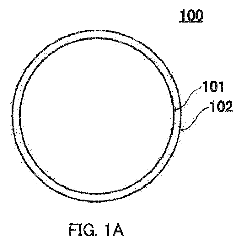
- a resin particle having a core-shell structure may be resin particle 100 composed of core particle 101 covered by sheet-like shell resin 102 as illustrated in FIG. 1A , which is a schematic sectional view of an embodiment of a resin particle having a core-shell structure, or may be resin particle 100 composed of core particle 101 covered by particle-like shell resin 102 as illustrated in FIG. 1B , which is a schematic sectional view of another embodiment.
- An average particle size of the core resin is preferably 1 ⁇ m or larger and 200 ⁇ m or smaller.
- the average particle size is 1 ⁇ m or larger, a powder material is easily handled during three-dimensional fabrication since such a powder material exhibits satisfactory flowability.
- the core resin is easily prepared without increasing manufacturing costs of such a powder material.
- the average particle size is 200 ⁇ m or smaller, fabrication of further highly accurate three-dimensional objects becomes possible.
- the average particle size of the core resin is preferably 2 ⁇ m or larger and 150 ⁇ m or smaller, more preferably 5 ⁇ m or larger and 100 ⁇ m or smaller, further preferably 5 ⁇ m or larger and 70 ⁇ m or smaller, and still further preferably 10 ⁇ m or larger and 60 ⁇ m or smaller.
- cross-sections of many resin particles are imaged using a TEM, the thickness of the shell resin is measured at 10 points for randomly selected 10 resin particles in the obtained image, and their average value is regarded as an average thickness of the shell resin.
- an average thickness of the shell resin is preferably smaller than an average particle size of the core resin, and more preferably equal to or less than the half of an average particle size of the core resin. Specifically, 2 ⁇ m or more and 75 ⁇ m or less is preferable. When the average particle size is 2 ⁇ m or more, aggregation of resin particles during preheating is readily suppressed. Meanwhile, when the average particle size is 75 ⁇ m or less, deformation of an object, such as curving, is readily suppressed.
- the average thickness of the shell resin is preferably 2 ⁇ m or more and 50 ⁇ m or less, more preferably 3 ⁇ m or more and 50 ⁇ m or less, and further preferably 5 ⁇ m or more and 30 ⁇ m or less.
- An average particle size of particles herein refers to a volume-average particle size measured by a dynamic light scattering method.
- the volume-average particle size can be measured using a laser diffraction-type particle size analyzer equipped with a wet disperser (from Sympatec GmbH, HELOS).
- the amounts of a core resin and a shell resin are not limited provided that the above-described resin particles having a core-shell structure are formed.
- the amount of a shell resin is preferably 0.1 part by weight or more and 20 parts by weight or less, more preferably 0.5 part by weight or more and 20 parts by weight or less, further preferably 0.5 part by weight or more and 15 parts by weight or less, still further preferably 1 part by weight or more and 15 parts by weight or less, and even still further preferably 1 part by weight or more and 10 parts by weight or less, relative to 100 parts by weight of a core resin.
- the powder material may further contain a laser absorber from a viewpoint of more efficiently converting light energy of a laser into thermal energy.
- a laser absorber may be any material that absorbs a laser of a wavelength used and generates heat. Examples of such laser absorbers include carbon powders, nylon resin powders, pigments, and dyes. These laser absorbers may be used alone or in combinations of two types.
- the amount of a laser absorber may be set appropriately within a range that facilitates fusing of resin particles having a core-shell structure, and may be more than 0% by mass and less than 3% by mass, based on the total mass of the powder material, for example.
- the powder material may further contain a flow agent.
- the flow agent may be any self-lubricating material with a low friction coefficient. Examples of such flow agents include silicon dioxide and boron nitride.
- the flow agent may be used alone or in combinations of two types.
- the amount of a flow agent may be set appropriately provided that flowability of the powder material is enhanced and resin particles having a core-shell structure are fused satisfactorily, and may be more than 0% by mass and less than 2% by mass, based on the total mass of the powder material, for example.
- the embodiment relates to a manufacturing method for the powder material.
- Resin particles having a core-shell structure can be used as the powder material without additional processing.
- the powder material may be obtained by stirring/mixing powders of the other materials with resin particles having a core-shell structure.
- Resin particles of the present invention can be manufactured according to a commonly known method of manufacturing particles having a core-shell structure using resin materials.
- Examples of such methods include a wet coating process using a coating solution of a shell resin, a dry coating process in which a core resin and a shell resin are stirred/mixed so as to be bonded with each other by mechanical impacting, and combinations thereof.
- the coating solution may be applied on the surface of a core resin by spray coating, or a core resin may be immersed in the coating solution.
- a resin particle composed of a core particle covered by particle-like shell resin is obtained as illustrated in FIG. IB.
- a resin particle composed of a core particle covered by a sheet-like shell resin is obtained as illustrated in FIG. 1A .
- the wet coating process readily forms a shell layer having a uniform thickness, whereas the dry coating process can simplify manufacturing processes by eliminating a drying step.
- a core resin and a shell resin are selected so that a temperature TS (6.5) at which a storage modulus G' of a material for the shell resin becomes 1 ⁇ 10 6.5 Pa is higher than a temperature TC (6.5) at which a storage modulus G' of a material for the core resin becomes 1 ⁇ 10 6.5 Pa.
- a core resin and a shell resin may be commercially available ones, or either or both of the resins may be synthesized using an appropriate monomer and/or a prepolymer, for example.
- Tg polyethylene, polypropylene, or polystyrene, which tends to have a lower Tg, is selected as a core resin, and a polyether ether ketone (PEEK), a polycarbonate, or an acrylic polymer, which tends to have a higher Tg, is selected as a shell resin.
- PEEK polyether ether ketone
- Tg of each commercial resin is reported from respective manufacturers.
- a storage modulus G' of the resin to be manufactured can be controlled within a desired range by changing an average molecular weight of the resin. Specifically, a storage modulus G' of the resin becomes higher as an average molecular weight of the resin to be manufactured becomes larger, whereas a storage modulus G' of the resin becomes lower as an average molecular weight of the resin to be manufactured becomes smaller.
- a relationship between a molecular weight and a temperature at which a storage modulus G' becomes 1 ⁇ 10 6.5 Pa is investigated in advance for each resin to be used, and a molecular weight of the resin to be manufactured may be determined with reference to such a relationship during the subsequent manufacture of the resin.
- the embodiment relates to a method of fabricating a three-dimensional object using the above-described powder materials.
- the method of the embodiment can be performed similarly to common powder bed fusion except for using the above-described powder materials.
- the method of the embodiment includes steps of (1) forming a thin layer of the powder material, (2) preheating the formed thin layer of the powder material, (3) forming an object layer by selectively irradiating the preheated thin layer with a laser beam to fuse resin particles contained in the powder material, and (4) laminating a plurality of the object layers by repeating steps 1 to 3 in this order a plurality of times.
- One of object layers constituting a three-dimensional object is formed in step 3, and a final three-dimensional object is manufactured by further repeating steps 1 to 3 in step 4 so as to laminate subsequent layers of the three-dimensional object.
- Step 1 Step of Forming Thin Layer of Powder Material
- a thin layer of the powder material is formed.
- the powder material supplied from a powder supply section is spread evenly on a build stage by a recoater.
- the thin layer may be formed directly on a build stage, or may be formed on an already spread powder material or on an already formed object layer.
- the thickness of the thin layer is set to be the same as the thickness of an object layer.
- the thickness of the thin layer may optionally be set corresponding to the accuracy of a three-dimensional object to be fabricated, it is typically 0.01 mm or more and 0.30 mm or less.
- By setting the thickness of the thin layer to 0.01 mm or more fusing of resin particles in an underneath layer can be prevented during laser irradiation for forming a subsequent layer.
- resin particles contained in a powder material, which forms the thin layer can be fused satisfactorily over the entire thickness direction by transferring laser energy to a lower portion of the thin layer.
- the thickness of the thin layer is more preferably 0.01 mm or more and 0.10 mm or less. Further, from a viewpoint of satisfactorily fusing resin particles over the entire thickness direction of the thin layer and suppressing cracking between laminated layers, the thickness of the thin layer is preferably set so that a difference between the thickness of the thin layer and a beam spot diameter of a laser described hereinafter becomes 0.10 mm or less.
- step 2 Step of Preheating Formed Thin Layer of Powder Material
- the formed thin layer of the powder material is preheated.
- a difference between a surface temperature of the preheated thin layer and the above-mentioned standby temperature is preferably 5°C or more and 50°C or less, and more preferably 5°C or more and 30°C or less.
- Step 3 Step of Forming Object Layer through Fusing of Resin Particles Having Core-shell Structure (step 3)
- the preheated thin layer in positions where an object layer is to be formed, is selectively irradiated with a laser to fuse resin particles in the irradiated positions.
- Fused resin particles melt together with adjacent powders to form a fused body, thereby forming an object layer.
- resin particles that have received laser energy are fused with a resin material in an already formed layer, and consequently adhesion between adjacent layers also results.
- the wavelength of a laser may be set within a range that is absorbed by a material for the shell resin.
- a difference between the wavelength of a laser and a wavelength at which a material for the shell resin has the highest absorptance is preferably set to be small. Since resins can absorb light in various wavelength regions, however, a laser with a wide wavelength band, such as a CO 2 laser, is preferably used.
- the wavelength of a laser is preferably 0.8 ⁇ m or longer and 12 ⁇ m or shorter.
- Output conditions of a laser may be set so that a storage modulus G' of a material for the core resin becomes 1 ⁇ 10 4.0 Pa or higher and lower than 1 ⁇ 10 8.0 Pa.
- the output power of a laser may be set within a range in which a material for the shell resin is satisfactorily fused at a scanning speed of a laser described hereinafter. Specifically, the output power may be 5.0 W or higher and 60 W or lower. From a viewpoint of lowering laser energy, decreasing fabrication costs, and simplifying the configuration of a fabrication apparatus, the output power of a laser is preferably 30 W or lower, and more preferably 20 W or lower.
- a scanning speed of a laser may be set within a range without increasing fabrication costs or requiring an excessively complex apparatus configuration.
- the scanning speed is preferably 1 mm/s or faster and 100 mm/s or slower, more preferably 1 mm/s or faster and 80 mm/s or slower, further preferably 2 mm/s or faster and 80 mm/s or slower, still further preferably 3 mm/s or faster and 80 mm/s or slower, and even still further preferably 3 mm/s or faster and 50 mm/s or slower.
- the beam diameter of a laser can be set appropriately corresponding to the accuracy of three-dimensional objects to be fabricated.
- At least step 3 is preferably performed under a reduced pressure or an inert gas atmosphere from a viewpoint of preventing lowering in strength of a three-dimensional object due to, for example, oxidation of resin particles during fusing.
- the reduced pressure is preferably 1 ⁇ 10 -2 Pa or lower, and more preferably 1 ⁇ 10 -3 Pa or lower.
- the inert gases that can be used in the embodiment include nitrogen gas and a noble gas. Among these inert gases, nitrogen (N 2 ) gas, helium (He) gas, or argon (Ar) gas is preferable due to its availability. From a viewpoint of simplifying the fabrication processes, all steps 1 to 3 are preferably performed under a reduced pressure or an inert gas atmosphere.
- the embodiment relates to an apparatus for fabricating a three-dimensional object using the above-described powder materials.
- the apparatus of the embodiment can be configured similarly to a commonly known apparatus for fabricating a three-dimensional object by powder bed fusion except for using the above-described powder materials.
- three-dimensional fabrication apparatus 200 of the embodiment includes: as illustrated in FIG.
- FIG. 2 that is a schematic side view of a configuration thereof, build stage 210 located inside an opening; thin layer forming section 220 that forms, on the build stage, a thin layer of a powder material containing resin particles having a core-shell structure; preheating section 230 that preheats the thin layer formed on the build stage; laser irradiation section 240 that irradiates the thin layer with a laser to form an object layer through fusing of the resin particles; stage support section 250 that supports build stage 210 such that a position thereof in the vertical direction is changed; and base 290 that supports each of the above sections.
- three-dimensional fabrication apparatus 200 may include: control section 260 that controls thin layer forming section 220, preheating section 230, laser irradiation section 240, and stage support section 250 such that an object layer is repeatedly formed and laminated; display section 270 for showing various information; operation section 275 including a pointing device and the like for receiving instructions from a user; storage section 280 that stores various information, such as a control program executed by control section 260; and data input section 285 including an interface and the like for transmitting/receiving various information, such as three-dimensional fabrication data, to/from an external apparatus.
- control section 260 controls thin layer forming section 220, preheating section 230, laser irradiation section 240, and stage support section 250 such that an object layer is repeatedly formed and laminated
- display section 270 for showing various information
- operation section 275 including a pointing device and the like for receiving instructions from a user
- storage section 280 that stores various information, such as a control program executed by control section 260
- the three-dimensional fabrication apparatus may further include temperature measuring instrument 235 that measures a temperature in a region where an object layer is to be formed on the surface of the thin layer formed on build stage 210.
- Computer apparatus 300 for creating three-dimensional fabrication data may be connected with three-dimensional fabrication apparatus 200.
- a three-dimensional object is fabricated on build stage 210 by forming a thin layer by thin layer forming section 220, preheating the thin layer by preheating section 230, and irradiating the thin layer with a laser by laser irradiation section 240 to form an object layer, and laminating such object layers.
- Thin layer forming section 220 may include, for example, powder supply section 221 having an opening, whose edge portion is substantially on the same plane in the horizontal direction as the edge portion of an opening where build stage 210 is elevated/lowered, a powder material reservoir section that extends downward in the vertical direction in the opening, and a supply piston that is elevated/lowered inside the opening in the bottom portion of the powder reservoir section; and recoater 222a that spreads supplied powder material evenly on build stage 210 to form a thin layer of the powder material.
- powder supply section 221 may include a powder reservoir section provided above build stage 210 in the vertical direction and a nozzle such that a powder material is discharged onto the same plane in the horizontal direction as the build stage.
- Preheating section 230 may have any configuration that can heat a region where an object layer is to be formed on the surface of the thin layer and maintain its temperature.
- preheating section 230 may include first heater 231 that can heat the surface of a thin layer formed on build stage 210, or further include second heater 232 that heats a powder material before being supplied to the build stage.
- preheating section 230 may be configured to selectively heat a region where the above-mentioned object layer is to be formed, or may be configured to heat inside the whole apparatus in advance and then adjust the surface of the thin layer to a predetermined temperature.
- Temperature measuring instrument 235 may be any instrument that enables noncontact measurement of a surface temperature in a region where the object layer is to be formed, and may be an IR sensor or an optical pyrometer, for example.
- Laser irradiation section 240 includes laser source 241 and galvano mirror 242a. Laser irradiation section 240 may further include laser window 243 that allows transmission of a laser and a lens (not shown) for setting the focal length of the laser on the surface of a thin layer.
- Laser source 241 may be any light source that emits a laser of the above-mentioned wavelength at the above-mentioned output. Examples of laser sources 241 include a YAG laser source, a fiber laser source, and a CO 2 laser source.
- Galvano mirror 242a may be composed of an X mirror and a Y mirror for reflecting a laser emitted from laser source 241 and scanning X and Y directions with the laser, respectively.
- Laser window 243 may be formed of any material that allows transmission of a laser.
- Stage support section 250 supports build stage 210 such that a position thereof in the vertical direction is changed.
- build stage 210 is configured to be moved accurately in the vertical direction by stage support section 250.
- stage support section 250 may be composed of a holding member that holds build stage 210, a guide member that guides the holding member in the vertical direction, and a ball screw that engages with a screw hole provided in the guide member.
- Control section 260 includes a hardware processor, such as a central processing unit, and controls operations of the entire three-dimensional fabrication apparatus 200 during fabrication operations for three-dimensional objects.
- a hardware processor such as a central processing unit
- Control section 260 may be configured, for example, to convert three-dimensional fabrication data acquired by data input section 285 from computer apparatus 300 into a plurality of slice data that is thinly sliced in the lamination direction of object layers.
- the slice data is fabrication data of each object layer for fabricating a three-dimensional object.
- the thickness of the slice data i.e., the thickness of the object layer, agrees with a distance corresponding to the thickness of one object layer (lamination pitch).
- Display section 270 may be a liquid crystal display or monitor, for example.
- Operation section 275 may include a pointing device, such as a keyboard or a mouse, and may be equipped with various operation keys, such as a numerical keypad, an execution key, and a start key.
- a pointing device such as a keyboard or a mouse
- various operation keys such as a numerical keypad, an execution key, and a start key.
- Storage section 280 may include various storage media, such as ROM, RAM, a magnetic disk, a HDD, and a SSD.
- Three-dimensional fabrication apparatus 200 may include a pressure-reducing section (not shown), such as a pressure-reducing pump, that reduces pressure inside the apparatus under control of control section 260, or an inert gas supply section (not shown) that supplies an inert gas inside the apparatus under control of control section 260.
- a pressure-reducing section such as a pressure-reducing pump
- an inert gas supply section (not shown) that supplies an inert gas inside the apparatus under control of control section 260.
- Control section 260 converts three-dimensional fabrication data acquired by data input section 285 from computer apparatus 300 into a plurality of slice data that is thinly sliced in the lamination direction of object layers. Control section 260 then controls the operations below of three-dimensional fabrication apparatus 200.
- Powder supply section 221 drives a motor and a driving mechanism (neither shown) according to supply information, which is output from control section 260, to move a supply piston upward in the vertical direction (arrow direction in FIG. 2 ), and thus push a powder material on the same plane in the horizontal direction as the build stage.
- recoater driving section 222 moves recoater 222a in the horizontal direction (arrow direction in FIG. 2 ) according to thin layer formation information, which is output from control section 260, to transfer the powder material onto build stage 210 while pressing the powder material such that the thickness of its thin layer corresponds to the thickness of one object layer.
- Preheating section 230 heats, according to temperature information output from control section 260, the surface of a thin layer formed or inside the entire apparatus.
- the temperature information may be information for heating the surface of the thin layer to a temperature that is retrieved by control section 260 from storage section 280, based on data (input from data input section 285) on a temperature TC (6.5) at which a storage modulus G' of a material for the core resin becomes 1 ⁇ 10 6.5 Pa, such that a difference from the temperature TC (6.5) is 5°C or more and 50°C or less.
- Preheating section 230 may start heating after a thin layer is formed, or may heat a location corresponding to the surface of a thin layer to be formed or inside the apparatus before a thin layer is formed.
- laser irradiation section 240 emits a laser from laser source 241 to a region of each slice data on a thin layer where a three-dimensional object is to be formed, and drives galvano mirror 242a by galvano mirror driving section 242 to scan with the laser.
- galvano mirror 242a by galvano mirror driving section 242 to scan with the laser.
- stage support section 250 drives a motor and a driving mechanism (neither shown) according to position control information, which is output from control section 260, to move build stage 210 downward in the vertical direction (arrow direction in FIG. 2 ) by a lamination pitch.
- Display section 270 shows, as needed, various information and/or messages to be recognized by a user under control of control section 260.
- Operation section 275 receives various input operations by a user and outputs operation signals corresponding to the input operations to control section 260. For example, a virtual three-dimensional object to be formed may be shown in display section 270 to confirm whether a desired shape is formed, and corrections may be added from operation section 275 if a desired shape is not formed.
- Control section 260 stores data in storage section 280 or retrieves data from storage section 120 as needed.
- Control section 260 may receive, from temperature measuring instrument 235, temperature information on a region where an object layer is to be formed on the surface of a thin layer, and control heating by preheating section 230 such that a difference between a temperature in the region where an object layer is to be formed and the temperature TC (6.5) at which a storage modulus G' of a material for the core resin becomes 1 ⁇ 10 6.5 Pa is 5°C or more and 50°C or less, and preferably 5°C or more and 30°C or less.
- object layers are laminated, thereby fabricating a three-dimensional object.
- Resins shown in Table 1 were prepared as materials for a core resin and a shell resin. Specifically, CALIBRE 301-4 (from Sumika Styron Polycarbonate Limited) was used as No. 1, 2, and 12 polycarbonate, PM 970W (from Sunallomer Ltd.) was used as No. 3 polypropylene, GR-2000 (from Denka Company Limited) was used as No. 4 ABS, Amilan CM 1001 (from Toray Industries, Inc.) was used as No. 5 nylon 6, F 022NH (from Ube-Maruzen Polyethylene Co., Ltd.) was used for No. 6 polyethylene, FMS-783 (from Japan U-Pica Company Ltd.) was used as No.
- the numerical values in the column of "average particle size” each represent the particle size (unit: ⁇ m) of the respective resins
- the numerical values in the column of "TC(65)” each represent a temperature at which a storage modulus G' becomes 1 ⁇ 10 6.5 Pa
- the numerical values in the column of "TC(70)” each represent a temperature at which a storage modulus G' becomes 1 ⁇ 10 7.0 Pa
- the numerical value ranges in the column of "TC(40 - 60)” each represent a temperature range in which a storage modulus G' becomes 1 ⁇ 10 4.0 Pa or higher and 1 ⁇ 10 6.0 Pa or lower.
- TC(65), TC(70), and TC(40 - 60) in Table 1 are values obtained by measuring according to the following method using a storage modulus measuring apparatus (from TA Instruments, ARES-G2 rheometer).
- a powder material was pressed at ambient temperature and at 30 kN for 1 minute using a press (from NPa System Co., Ltd., NT-100H) to yield a columnar sample with a diameter of about 8 mm and a height of about 2 mm.
- the prepared columnar sample was heat-melted, and then attached to parallel plates of the press, whose temperatures had been adjusted to 150°C, under load in the vertical direction without exceeding an axial force of 10 gw. Under such a state, the parallel plates and the columnar sample were heated to a measurement start temperature of 250°C, and viscoelasticity data was measured while the parallel plates and the columnar sample were cooled gradually.
- the measured data was forwarded to a computer in which Windows 7 is installed (from Microsoft Corporation), and a storage modulus G' (Pa) value at each temperature was read through control, data collection, and analysis software (TRIOS) that operates on the computer.
- Windows 7 is installed (from Microsoft Corporation)
- TRIOS storage modulus G'
- Measurement frequency 6.28 rad/s Setting of measurement strain: set to initial value of 0.1% and measured in an automatic measurement mode Elongation correction of sample: adjusted in an automatic measurement mode Measurement temperature: gradual cooling from 250°C to 100°C at 5°C/min Measurement interval: viscoelasticity data measured every 1°C Table 1: Resins No.
- Powder materials 2, 4 to 9, and 11 were obtained in a similar manner to that for powder material 1 except for combining resins as shown in Table 2.
- powder materials 2 and 4 were prepared in a similar procedure to that for powder material 1 except for changing the core resin from resin 1 to resin 2 and 3, respectively, powder material 5 was prepared in a similar procedure to that for powder material 1 except for changing the core resin from resin 1 to resin 3 and the shell resin from resin 8 to resin 10, powder material 6 was prepared in a similar procedure to that for powder material 1 except for changing the core resin from resin 1 to resin 4 and the shell resin from resin 8 to resin 10, powder material 7 was prepared in a similar procedure to that for powder material 1 except for changing the core resin from resin 1 to resin 5 and the shell resin from resin 8 to resin 10, powder material 8 was prepared in a similar procedure to that for powder material 1 except for changing the core resin from resin 1 to resin 6 and the shell resin from resin 8 to resin 11, powder material 9 was prepared in a similar procedure to that for powder material 1 except for changing the core resin from resin 1 to resin 7 and the shell resin from resin
- Polymer dispersion 1 was obtained by dissolving 1 part by weight of resin 9 and 2 parts by weight of an emulsifier (from Sakamoto Yakuhin Kogyo Co., Ltd., CRS-75) in 100 parts by weight of toluene, and further dispersing 10 parts by weight of resin 1.
- Polymer dispersion 1 was fed into a solution of 10 parts by weight of a nonionic surfactant (from Kao Corporation, Emanon C-25 ("Emanon" is a registered trade mark of the firm)) dissolved in 200 parts by weight of water, and ultrasonication was performed for 10 minutes to yield resin dispersion 2.
- Resin dispersion 2 was fed into an evaporator, and toluene was removed under a reduced pressure to yield a resin dispersion. The resulting resin dispersion was then filtered under a reduced pressure to yield powder material 3.
- Resin 1 was used as powder material 10 without further processing.
- Resin particles were dispersed in a photocurable resin (from JEOL Ltd., D-800) and then photocured to form a block. From the block, a 100 to 200 nm-thick thin sample was cut using a microtome equipped with a diamond blade and mounted on a support film-attached grid for transmission electron microscope observation. The grid was placed in a scanning transmission electron microscope (from JEOL Ltd., JSM-7401F), and a bright-field image was taken under the following conditions.
- a photocurable resin from JEOL Ltd., D-800
- Table 2 shows materials used for preparation of powder materials 1 to 11 and their coverages.
- the numerical value ranges in the column of "TC(40-60)” each represent a temperature range in which a storage modulus G' becomes 1 ⁇ 10 4.0 Pa or higher and 1 ⁇ 10 6.0 Pa or lower.
- the numerical values in the column of "TC(70)-TC(65)” are each absolute values obtained by subtracting TC(65) of the core resin from TC(70) of the core resin
- the numerical values in the column of "TS(65)-TC(65)” are each absolute values obtained by subtracting TC(65) of the core resin from TS(65) of the shell resin.
- Table 2 Powder Materials 1 to 11 Powder material No.
- Powder materials 1 to 11 were each spread on a build stage, which was placed inside a large electric furnace, to form a 0.1 mm-thick thin layer, and heated to a preheating temperature shown in Table 3 by adjusting the temperature of the electric furnace. Under the following conditions, a 15 mm ⁇ 20 mm range of the thin layer was irradiated with a laser from a 50 W fiber laser (from SPI Lasers Limited) equipped with a galvanometer scanner for YAG wavelengths to form an object layer. By repeating the above process 10 times, objects 1 to 11 composed of laminated 10 layers were each fabricated.
- Laser output 20 W
- Laser wavelength 1.07 ⁇ m
- Beam diameter 170 ⁇ m on thin layer surface
- Table 3 shows powder materials used for fabrication of objects 1 to 11, fabrication conditions (preheating temperature and heating temperature during laser irradiation), and deviation in fabrication accuracy.
- Table 3 Powder materials, Fabrication conditions, and Results Object No. Powder material No. TC(65) (°C) Fabrication conditions Result Preheating temperature (°C) Heating temperature during laser irradiation (°C) Deviation in fabrication accuracy (mm) 1 1 160 170 250 0.1 2 2 160 170 250 0.2 3 3 160 170 250 0.1 4 4 120 170 250 0.1 5 5 120 230 340 0.1 6 6 120 230 340 0.1 7 7 220 230 340 0.1 8 8 100 230 300 0.1 9 9 130 230 300 0.1 10 10 160 150 250 1.0 11 11 160 150 230 1.0
- Fabrication accuracy was enhanced when an object was fabricated from a powder material (powder material 1 to 9) in which powder particles each including a core resin and a shell resin covering the core resin, and a temperature at which a storage modulus G' of a material for the shell resin becomes 1 ⁇ 10 6.5 Pa is higher than a temperature at which a storage modulus G' of a material for the core resin becomes 1 ⁇ 10 6.5 Pa.
Landscapes
- Chemical & Material Sciences (AREA)
- Engineering & Computer Science (AREA)
- Materials Engineering (AREA)
- Manufacturing & Machinery (AREA)
- Health & Medical Sciences (AREA)
- Chemical Kinetics & Catalysis (AREA)
- Medicinal Chemistry (AREA)
- Polymers & Plastics (AREA)
- Organic Chemistry (AREA)
- Physics & Mathematics (AREA)
- Optics & Photonics (AREA)
- Mechanical Engineering (AREA)
Abstract
Description
- The present invention relates to a powder material, a method of fabricating a three-dimensional object, and a three-dimensional fabrication apparatus.
- Various methods of relatively easily fabricating complex-shaped three-dimensional objects have been developed in recent years. As one of such methods of fabricating three-dimensional objects, powder bed fusion is known. Powder bed fusion features high fabrication accuracy and high interlayer adhesion of laminated layers. Accordingly, powder bed fusion is applicable not only to creation of prototypes for confirming the shape or properties of final products, but also to fabrication of final products.
- In powder bed fusion, one of finely sliced layers in the thickness direction of a three-dimensional object (hereinafter, also simply referred to as "object layer") is formed by evenly spreading a powder material containing powder particles of a resin material or a metal material to form a thin layer, and irradiating desired positions on the thin layer with a laser to selectively fuse the powder particles. On the thus-formed layer, a subsequent object layer is formed by further spreading the powder material, and irradiating the powder material with the laser to selectively fuse the powder particles. By repeating the above procedure while laminating object layers, a three-dimensional object having a desired shape is fabricated. In this process, in some cases, such a powder material is preheated before laser irradiation in order to fuse powder particles by shorter-time laser irradiation.
- Patent Literature (hereinafter, abbreviated as PTL) 1 to 3 describe examples of powder materials for powder bed fusion that can improve characteristics of three-dimensional objects to be fabricated.
-
PTL 1 describes a powder material containing powder particles each including a core particle formed of a material containing a resin, a first coating of a polar material (polyvinylpyrrolidone or an acrylic polymer, for example) covering the core particle, and a second coating of a surfactant further covering the first coating. According toPTL 1, since a nonpolar part of the surfactant faces outward in the second coating, which is the outermost layer, the powder particles are less susceptible to agglomeration due to absorption of water from the air. Therefore, in three-dimensional fabrication using such powder particles, three-dimensional objects are to be less likely to shrink due to agglomeration of powder particles before fabrication. - PTL 2 describes a powder material containing powder particles each including a core particle of a thermoplastic resin and aggregation inhibitor particles that cover the core particle and have an average particle size of 1 µm or smaller. According to PTL 2, such powder particles exhibit high flowability, and thus powder particles before laser irradiation can be spread highly densely. Therefore, in three-dimensional fabrication using such powder particles, an object having high mechanical strength can reportedly be fabricated.
- PTL 3 describes a powder material containing main powders and a laser-absorbing coloring material (carbon, for example) that can absorb a laser of a shorter wavelength than a wavelength of a laser that the main powders can absorb. According to PTL 3, the powder material enables three-dimensional fabrication using a laser of a shorter wavelength than that employed in the conventional process. Since a beam diameter of a laser can be decreased, a more highly accurate three-dimensional object can reportedly be fabricated.
-
-
PTL 1
Japanese Unexamined Patent Application Publication (Translation ofPCT Application) No. 2005-533877 - PTL 2
Japanese Patent Application Laid-Open No.2006-321711 - PTL 3
Japanese Patent Application Laid-Open No.2010-184412 - As three-dimensional objects fabricated by powder bed fusion are applied more widely, there is a need for three-dimensional fabrication using materials different from conventional ones, especially resin materials. Such resin materials, however, have a problem in which the majority of particles tend to deform at a high temperature in the fabrication process, and thus fabrication accuracy is difficult to be enhanced. Accordingly, there is a need for a technique that enables fabrication of highly accurate three-dimensional objects by powder bed fusion using various resin materials.
- The powder material described in
PTL 1 can reportedly fabricate highly accurate three-dimensional objects. According to the powder material described in PTL 2, powder particles can be spread highly densely. Therefore, highly accurate three-dimensional objects are expected to be fabricated since voids are less likely to be formed in the spread powder particles and thus deformation of the powder particles is suppressed. According to the powder material of PTL 3, a short-wavelength laser beam can be employed by incorporating a laser-absorbing coloring material, such as carbon, instead of a resin as main powders, and thus a highly accurate three-dimensional object is expected to be fabricated. The studies by the present inventors, however, found that three-dimensional objects with desired accuracy were difficult to be fabricated using various types of resins even when the powder materials described inPTL 1, 2, and 3 were used. - In view of the above-mentioned problems, one object of the present invention is to provide a powder material containing powder particles formed of a resin for powder bed fusion, which is a powder material that enables fabrication of a further highly accurate three-dimensional object. Another object of the present invention is to provide a method of fabricating a three-dimensional object using such a powder material and to provide a three-dimensional fabrication apparatus.
- A first aspect of the present invention relates to the following powder material.
- [1] A powder material used for fabrication of a three-dimensional object by selectively irradiating a thin layer of a powder material containing powder particles with a laser beam to form an object layer through fusing of the powder particles, and laminating the object layer, in which:
- the powder particles each include a core resin and a shell resin that covers the core resin; and
- a temperature TS(6.5) at which a storage modulus G' of a material for the shell resin becomes 1 × 106.5 Pa is higher than a temperature TC(6.5) at which a storage modulus G' of a material for the core resin becomes 1 × 106.5 Pa.
- [2] The powder material according to [1], in which a difference between the temperature TS(6.5) at which a storage modulus G' of a material for the shell resin becomes 1 × 106.5 Pa and the temperature TC(6.5) at which a storage modulus G' of a material for the core resin becomes 1 × 106.5 Pa is 5°C or more and 70°C or less.
- [3] The powder material according to [1] or [2], in which the temperature TC(6.5) at which a storage modulus G' of a material for the core resin becomes 1 × 106.5 Pa is 50°C or higher and 300°C or lower.
- [4] The powder material according to any one of [1] to [3], in which the temperature TS(6.5) at which a storage modulus G' of a material for the shell resin becomes 1 × 106.5 Pa is 100°C or higher and 350°C or lower.
- [5] The powder material according to any one of [1] to [4], in which the core resin is formed of a material having a difference between a temperature TC(7.0) at which a storage modulus G' becomes 1 × 107.0 Pa and a temperature TC(6.5) at which a storage modulus G' becomes 1 × 106.5 Pa is 10°C or more and 100°C or less.
- [6] The powder material according to any one of [1] to [5], in which an average particle size of the core resin is 1 µm or larger and 200 µm or smaller.
- [7] The powder material according to any one of [1] to [6], in which an amount of the shell resin in the powder particle is 0.1 part by weight or more and 20 parts by weight or less, relative to 100 parts by weight of the core resin.
A second aspect of the present invention relates to the following method of fabricating a three-dimensional object. - [8] A method of fabricating a three-dimensional object, including:
- forming a thin layer of the powder material containing the powder particles according to any one of [1] to [7];
- preheating the formed thin layer of the powder material;
- forming an object layer by selectively irradiating the preheated thin layer with a laser beam to fuse the powder particles contained in the powder material; and
- laminating a plurality of the object layers by repeating the forming of the thin layer, the preheating, and the forming of the object layer in this order a plurality of times.
- [9] The method according to [8], in which in the preheating, the thin layer is heated to a temperature at which a difference between a surface temperature of the thin layer and the temperature TC(6.5) at which a storage modulus G' of a material for the core resin becomes 1 × 106.5 Pa is 5°C or more and 50°C or less.
- [10] The method according to [8] or [9], in which in the forming of the object layer, the thin layer is selectively irradiated with the laser beam such that a storage modulus G' of a material for the core resin becomes 1 × 104.0 Pa or higher and 1 × 106.0 Pa or lower.
A third aspect of the present invention relates to the following three-dimensional fabrication apparatus. - [11] A three-dimensional fabrication apparatus including:
- a build stage;
- a thin layer forming section that forms, on the build stage, a thin layer of the powder material containing the powder particles according to any one of [1] to [7];
- a preheating section that preheats the formed thin layer of the powder material;
- a laser irradiation section that irradiates the thin layer with a laser to form an object layer through fusing of the powder particles;
- a stage support section that supports the build stage such that a position of the build stage in a vertical direction is changed; and
- a control section that controls the thin layer forming section, the laser irradiation section, and the stage support section such that the object layer is repeatedly formed and laminated.
- [12] The three-dimensional fabrication apparatus according to [11], further including a temperature measuring instrument that measures a surface temperature of the formed thin layer of the powder material, in which:
the control section receives temperature information on a region where an object layer is to be formed on a surface of the thin layer, and controls heating by the preheating section such that a difference between a temperature on the surface of the thin layer in the region where an object layer is to be formed and the temperature TC(6.5) at which a storage modulus G' of a material for the core resin becomes 1 × 106.5 Pa is 5°C or more and 50°C or less. - The present invention provides a powder material containing powder particles formed of a resin for powder bed fusion, which is a powder material that enables fabrication of a further highly accurate three-dimensional object, a method of fabricating a three-dimensional object using such a powder material, and a three-dimensional fabrication apparatus.
-
-
FIG. 1A is a schematic sectional view of a resin particle of an embodiment of the present invention; -
FIG. 1B is a schematic sectional view of a resin particle of another embodiment of the present invention; -
FIG. 2 is a schematic side view of the configuration of a three-dimensional fabrication apparatus of the embodiment; and -
FIG. 3 illustrates the main part of a control system of the three-dimensional fabrication apparatus of the embodiment. - To solve the above-mentioned problems, the present inventors performed extensive investigation of and experiments on powder materials for powder bed fusion. As a result, the present inventors found that a further highly accurate three-dimensional object can be fabricated by using a powder material containing powder particles having a core-shell structure, in which a temperature TS(6.5) at which a storage modulus G' of a material for the shell resin becomes 1 × 106.5 Pa is higher than a temperature TC(6.5) at which a storage modulus G' of a material for the core resin becomes 1 × 106.5 Pa, thereby making the present invention.
- According to the findings newly obtained by the present inventors, when three-dimensional fabrication is performed by powder bed fusion using powder particles formed of a resin material (hereinafter, also simply referred to as "resin particles"), accuracy in three-dimensional fabrication lowers, in some cases, due to deformation of resin particles during preheating before laser irradiation.
- Resin particles used for powder bed fusion have the property of softening as the temperature rises. Accordingly, when a preheating temperature is elevated, resin particles soften excessively, and thus resin particles contained in a lower layer are crushed by the weight of resin particles deposited as an upper layer, thereby causing deformation. In this process, deformation of particles particularly in the lamination direction also leads to considerable deformation of an object layer, which is formed through fusing of resin particles, in the lamination direction, thereby lowering accuracy in three-dimensional fabrication. Meanwhile, when a preheating temperature is lowered, a change in specific volume of a resin increases during heating to a fusing temperature of resin particles. Therefore, the volume of resin particles changes significantly during laser irradiation, thereby still causing deformation of resin particles.
- The hardness of viscoelastic materials, such as resins, can be expressed by storage modulus G'. Resins have the property of decreasing storage modulus G' as the temperature rises. In order to suppress deformation of resin particles due to a large change in specific volume at the above-mentioned low temperature and to allow fusion of powder particles by shorter-time laser irradiation, it is preferable to set a temperature in preheating closer to a temperature at which a resin starts to soften (storage modulus G' of 1 × 106.5 Pa). At such a temperature, however, the above-described high temperature-caused deformation of resin particles slightly occurs (deformation due to softening of resin particles), and consequently accuracy in three-dimensional fabrication was unable to be enhanced to a desired level.
- As a result of further investigation based on the above findings, the present inventors found that when resin particles have a core-shell structure and materials are employed so that a resin for the shell (hereinafter, also simply referred to as "shell resin") has a storage modulus G' of 1 × 106.5 Pa at a higher temperature than a resin for the core (hereinafter, also simply referred to as "core resin"), the shell resin is less susceptible to deformation even when preheated to a temperature TC(6.5) at which a storage modulus G' of the core resin becomes 1 × 106.5 Pa, thereby suppressing deformation of the resin particles.
- The powder material of the present invention contains resin particles having the above-described characteristics (hereinafter, also simply referred to as "resin particles of the present invention"). During waiting for laser irradiation, resin particles of the present invention are preheated to around a temperature at which a storage modulus G' of a material for the core resin becomes 1 × 106.5 Pa (hereinafter, also simply referred to as "standby temperature"). Since a temperature at which a storage modulus G' of a material for the shell resin becomes 1 × 106.5 Pa is higher, a storage modulus G' of a material for the shell resin is higher than 1 × 106.5 Pa at around the standby temperature. Since resin particles of the present invention maintain hardness by outer films formed of the shell resin during the waiting, particles contained in a lower layer are presumably less susceptible to deformation due to the weight of resin particles deposited as an upper layer. Meanwhile, since resin particles are heated to around a temperature at which a storage modulus G' of a material for the core resin becomes 1 × 106.5 Pa by preheating, resin particles can be heated to a fusing temperature by less-energy irradiation, thereby enabling shorter-time three-dimensional fabrication. In addition, since the core resin is heated to the above-mentioned relatively high temperature, the specific volume of the core resin does not change much even when heated to a fusing temperature of resin particles by laser irradiation. Accordingly, deformation of the resin particles is believed to be less likely to occur due to volume changes during laser irradiation.
- In
PTL 1 to 3, the above-described issues arising from preheating are not fully considered.PTL 1, for example, discloses that when particles are used for 3D laser sintering, a softening temperature of a core should be satisfactorily higher than a softening temperature of an upper layer on the core. PTL 2 discloses that particles for improving sliding properties are attached to the surface of base particles in order to enhance filling properties of particles. There is, however, a problem in which softening of the base particles is difficult to be suppressed during preheating. Further, according to PTL 3, absorption of laser is enhanced by addition of carbon, for example. An issue involving preheating, i.e., aggregation of particles, however, cannot be resolved. - Hereinafter, representative embodiments of the present invention will be described in detail.
- The embodiment relates to a powder material used for fabrication of a three-dimensional object (hereinafter, also simply referred to as "powder material") by selectively irradiating a thin layer of a powder material containing powder particles with a laser beam to form an object layer through fusing of the powder particles, and laminating the object layer. The powder material contains, as the powder particles, resin particles having a core-shell structure of the present invention. The powder material may further contain materials other than the resin particles of the present invention, such as a laser absorber and a flow agent unless fusing by laser irradiation is obstructed.
- Resin particles having a core-shell structure, as the resin particles of the present invention, include a core resin and a shell resin that covers the core resin. A temperature at which a storage modulus G' of a material for the shell resin becomes 1 × 106.5 Pa (hereinafter, this temperature will simply be denoted as TS(6.5) in some cases) is higher than a temperature at which a storage modulus G' of a material for the core resin becomes 1 × 106.5 Pa (hereinafter, this temperature will simply be denoted as TC(6.5) in some cases).
- Materials for the core resin and the shell resin may be any resin provided that such a resin softens and melts by heating. Examples of the materials for the core resin and the shell resin include crystalline resins, such as polyethylene, polypropylene, a nylon, polyacetal, polyethylene terephthalate (PET), polyphenylene sulfide, a polyether ether ketone (PEEK), and a crystalline polyester; and amorphous resins, such as polystyrene, a polyurethane, polyvinyl chloride, acrylonitrile-butadiene-styrene copolymer (ABS), an acrylic polymer, a polycarbonate, ethylene-vinyl acetate copolymer (EVA), styrene-acrylonitrile copolymer (SAN), a polyarylate, a polyphenylene ether, and polycaprolactone.
- Amorphous resins, among the above resins, are difficult to enhance fabrication accuracy by conventional methods. According to the resin particles having a core-shell structure of the embodiment, however, fabrication accuracy can be enhanced further. In view of the above, a material for the core resin is preferably an amorphous resin.
- A temperature TS(6.5) at which a storage modulus G' of a material for the shell resin becomes 1 × 106.5 Pa is higher than a temperature TC(6.5) at which a storage modulus G' of a material for the core resin becomes 1 × 106.5 Pa. Such temperatures at which a storage modulus G' becomes 1 × 106.5 Pa and a temperature at which a storage modulus G' becomes each value mentioned hereinafter may be values obtained/measured according to a commonly known method. The above-mentioned storage modulus G' is a value obtained/measured according to the following method using a storage modulus measuring apparatus (from TA Instruments, ARES-G2 rheometer).
- A core resin or a shell resin of resin particles is separated and extracted using a solvent that only dissolves either the core resin or the shell resin, and dried as powders. The resulting powders are pressed at ambient temperature and at 30 kN for 1 minute using a press (from NPa System Co., Ltd., NT-100H) to yield a columnar sample with a diameter of about 8 mm and a height of about 2 mm
- The prepared columnar sample is heat-melted and then attached to parallel plates of the press, whose temperatures have been adjusted to 150°C, under load in the vertical direction without exceeding axial force of 10 gw. Under this state, the parallel plates and the columnar sample are heated to a measurement start temperature of 250°C, and viscoelasticity data is measured while the parallel plates and the columnar sample are cooled gradually. The measured data is forwarded to a computer on which Windows 7 (from Microsoft Corporation, "Windows" is a registered trade mark of the firm) is installed, and a storage modulus G' (Pa) value at each temperature is read through control, data collection, and analysis software (TRIOS) that operates on the computer.
- Measurement frequency: 6.28 rad/s
Setting of measurement strain: set to initial value of 0.1% and measured in an automatic measurement mode
Elongation correction of sample: adjusted in an automatic measurement mode
Measurement temperature: gradual cooling from 250°C to 100°C at 5°C/min
Measurement interval: viscoelasticity data measured every 1°C - The powder material containing resin particles having a core-shell structure of the embodiment exhibits higher fabrication accuracy than conventional powder materials when preheated to around a temperature at which a storage modulus G' of a material for the core resin becomes 1 × 106.5 Pa. Since a storage modulus G' of a material for the shell resin is higher than 1 × 106.5 Pa at this moment, outer films of resin particles formed of the shell resin are less likely to soften, and thus the resin particles are less susceptible to deformation. Meanwhile, once a laser is irradiated during fabrication, a material for the shell resin softens, melts, or disappears, thereby fusing the resin particles. From a viewpoint of facilitating softening, disappearing, and melting of the shell resin during laser irradiation, as well as promoting fusing of resin particles having a core-shell structure, and enabling shorter-time three-dimensional fabrication, it is preferable that a difference between a temperature at which a material for the shell resin softens, melts, or disappears and a temperature at which a material for the core resin softens and melts is small. Further, it is also preferable that the difference between the above temperatures is small from a viewpoint of decreasing a volume change due to an increased specific volume of the core resin by heating. Meanwhile, from a viewpoint of suppressing deformation of resin particles due to softening of a material for the shell resin at a standby temperature, it is also preferable that the difference between the above temperatures is not excessively small. The difference between the above temperatures can be estimated from a difference between a temperature TS(6.5) at which a storage modulus G' of a material for the shell resin becomes 1 × 106.5 Pa and a temperature TC(6.5) at which a storage modulus G' of a material for the core resin becomes 1 × 106.5 Pa. In view of the above, the difference between TS(6.5) and TC(6.5) is preferably 5°C or more and 70°C or less, more preferably 10°C or more and 70°C or less, further preferably 10°C or more and 60°C or less, still further preferably 30°C or more and 60°C or less.
- The temperature TC(6.5) at which a storage modulus G' of a material for the core resin becomes 1 × 106.5 Pa is preferably within an adjustable temperature range of the core resin through preheating by a commonly known apparatus employed in powder bed fusion. In view of the above, TC(6.5) is preferably 50°C or higher and 300°C or lower, more preferably 100°C or higher and 300°C or lower, further preferably 100°C or higher and 250°C or lower, still further preferably 140°C or higher and 250°C or lower, and even still further preferably 140°C or higher and 200°C or lower.
- Meanwhile, the temperature TS(6.5) at which a storage modulus G' of a material for the shell resin becomes 1 × 106.5 Pa is preferably within a temperature range that facilitates melting of a core resin by laser irradiation while ensuring freedom in selecting of a core resin. In view of the above, TS(6.5) is preferably 100°C or higher and 350°C or lower, more preferably 150°C or higher and 350°C or lower, further preferably 150°C or higher and 330°C or lower, still further preferably 250°C or higher and 330°C or lower, and even still further preferably 250°C or higher and 300°C or lower.
- From a viewpoint of further suppressing deformation of an object after laser irradiation, the core resin preferably solidifies in a shorter time during cooling after laser irradiation. In view of the above, a temperature difference between a softening temperature of a material for the core resin (temperature TC(6.5) at which a storage modulus G' becomes 1 × 106.5 Pa) and a temperature at which a material for the core resin becomes hard to an extent without deformation (temperature at which a storage modulus G' becomes 1 × 107.0 Pa (hereinafter, also denoted as TC(7.0) in some cases)) is preferably small. Specifically, an absolute difference between TC(7.0) and TC(6.5) (|TC(7.0) - TC(6.5)|) is preferably 10°C or more and 100°C or less, more preferably 10°C or more and 80°C or less, further preferably 15°C or more and 80°C or less, still further preferably 20°C or more and 80°C or less, and even still further preferably 20°C or more and 50°C or less.
- As for resin particles having a core-shell structure, in order to measure a temperature at which a storage modulus G' of the core resin becomes a specific numerical value, the resin particles having a core-shell structure may be measured for viscoelasticity characteristics according to above-described procedure without any change. Meanwhile, as for resin particles having a core-shell structure, in order to measure a temperature at which a storage modulus G' of the shell resin becomes a specific numerical value, the core component may be removed first, for example, by dissolving the resin particles in a solvent that only dissolves the core, and then the remaining shell resin may be measured for viscoelasticity characteristics according to the above-described procedure.
- A core-shell structure herein means that an area ratio of the surface of a core particle, which is basically formed of a core resin, covered by a shell resin is 90% or higher. Practically, cross-sections of many resin particles are imaged using a transmission electron microscope (TEM), a ratio of a core particle surface covered by a shell resin is measured for randomly selected 10 core particles in the obtained image, and the resin particles are considered to have a core-shell structure when their average value is 90% or higher.
- A resin particle having a core-shell structure may be
resin particle 100 composed ofcore particle 101 covered by sheet-like shell resin 102 as illustrated inFIG. 1A , which is a schematic sectional view of an embodiment of a resin particle having a core-shell structure, or may beresin particle 100 composed ofcore particle 101 covered by particle-like shell resin 102 as illustrated inFIG. 1B , which is a schematic sectional view of another embodiment. - An average particle size of the core resin is preferably 1 µm or larger and 200 µm or smaller. When the average particle size is 1 µm or larger, a powder material is easily handled during three-dimensional fabrication since such a powder material exhibits satisfactory flowability. In addition, when the average particle size is 1 µm or larger, the core resin is easily prepared without increasing manufacturing costs of such a powder material. Meanwhile, when the average particle size is 200 µm or smaller, fabrication of further highly accurate three-dimensional objects becomes possible. In view of the above, the average particle size of the core resin is preferably 2 µm or larger and 150 µm or smaller, more preferably 5 µm or larger and 100 µm or smaller, further preferably 5 µm or larger and 70 µm or smaller, and still further preferably 10 µm or larger and 60 µm or smaller. In the present specification, cross-sections of many resin particles are imaged using a TEM, the thickness of the shell resin is measured at 10 points for randomly selected 10 resin particles in the obtained image, and their average value is regarded as an average thickness of the shell resin.
- When a particle-like shell resin covers a core resin, an average thickness of the shell resin is preferably smaller than an average particle size of the core resin, and more preferably equal to or less than the half of an average particle size of the core resin. Specifically, 2 µm or more and 75 µm or less is preferable. When the average particle size is 2 µm or more, aggregation of resin particles during preheating is readily suppressed. Meanwhile, when the average particle size is 75 µm or less, deformation of an object, such as curving, is readily suppressed. The average thickness of the shell resin is preferably 2 µm or more and 50 µm or less, more preferably 3 µm or more and 50 µm or less, and further preferably 5 µm or more and 30 µm or less.
- An average particle size of particles herein refers to a volume-average particle size measured by a dynamic light scattering method. The volume-average particle size can be measured using a laser diffraction-type particle size analyzer equipped with a wet disperser (from Sympatec GmbH, HELOS).
- The amounts of a core resin and a shell resin are not limited provided that the above-described resin particles having a core-shell structure are formed. For example, the amount of a shell resin is preferably 0.1 part by weight or more and 20 parts by weight or less, more preferably 0.5 part by weight or more and 20 parts by weight or less, further preferably 0.5 part by weight or more and 15 parts by weight or less, still further preferably 1 part by weight or more and 15 parts by weight or less, and even still further preferably 1 part by weight or more and 10 parts by weight or less, relative to 100 parts by weight of a core resin.
- The powder material may further contain a laser absorber from a viewpoint of more efficiently converting light energy of a laser into thermal energy. Such a laser absorber may be any material that absorbs a laser of a wavelength used and generates heat. Examples of such laser absorbers include carbon powders, nylon resin powders, pigments, and dyes. These laser absorbers may be used alone or in combinations of two types.
- The amount of a laser absorber may be set appropriately within a range that facilitates fusing of resin particles having a core-shell structure, and may be more than 0% by mass and less than 3% by mass, based on the total mass of the powder material, for example.
- From a viewpoint of enhancing flowability of the powder material and facilitating handling of the powder material during three-dimensional fabrication, the powder material may further contain a flow agent. The flow agent may be any self-lubricating material with a low friction coefficient. Examples of such flow agents include silicon dioxide and boron nitride. The flow agent may be used alone or in combinations of two types.
- The amount of a flow agent may be set appropriately provided that flowability of the powder material is enhanced and resin particles having a core-shell structure are fused satisfactorily, and may be more than 0% by mass and less than 2% by mass, based on the total mass of the powder material, for example.
- The embodiment relates to a manufacturing method for the powder material. Resin particles having a core-shell structure can be used as the powder material without additional processing. When the powder material contains the above-mentioned other materials, the powder material may be obtained by stirring/mixing powders of the other materials with resin particles having a core-shell structure.
- Resin particles of the present invention can be manufactured according to a commonly known method of manufacturing particles having a core-shell structure using resin materials.
- Examples of such methods include a wet coating process using a coating solution of a shell resin, a dry coating process in which a core resin and a shell resin are stirred/mixed so as to be bonded with each other by mechanical impacting, and combinations thereof. When the wet coating process is employed, the coating solution may be applied on the surface of a core resin by spray coating, or a core resin may be immersed in the coating solution. According to the dry coating process, a resin particle composed of a core particle covered by particle-like shell resin is obtained as illustrated in FIG. IB. According to the wet coating process, a resin particle composed of a core particle covered by a sheet-like shell resin is obtained as illustrated in
FIG. 1A . The wet coating process readily forms a shell layer having a uniform thickness, whereas the dry coating process can simplify manufacturing processes by eliminating a drying step. - A core resin and a shell resin are selected so that a temperature TS(6.5) at which a storage modulus G' of a material for the shell resin becomes 1 × 106.5 Pa is higher than a temperature TC(6.5) at which a storage modulus G' of a material for the core resin becomes 1 × 106.5 Pa. Such a core resin and a shell resin may be commercially available ones, or either or both of the resins may be synthesized using an appropriate monomer and/or a prepolymer, for example.
- When commercial resins are used, commercial materials may be combined so that storage moduli G' measured according to the above-described method satisfy the above relationship. The above-described relationship can be predicted to be satisfied when a material having a lower temperature at which a storage modulus G' becomes 1 × 108.0 Pa (glass transition temperature (Tg)) is selected as a core resin, and a material having a higher Tg is selected as a shell resin. For example, the above relationship is satisfied when polyethylene, polypropylene, or polystyrene, which tends to have a lower Tg, is selected as a core resin, and a polyether ether ketone (PEEK), a polycarbonate, or an acrylic polymer, which tends to have a higher Tg, is selected as a shell resin. In many cases, Tg of each commercial resin is reported from respective manufacturers.
- When a resin is manufactured, a storage modulus G' of the resin to be manufactured can be controlled within a desired range by changing an average molecular weight of the resin. Specifically, a storage modulus G' of the resin becomes higher as an average molecular weight of the resin to be manufactured becomes larger, whereas a storage modulus G' of the resin becomes lower as an average molecular weight of the resin to be manufactured becomes smaller. A relationship between a molecular weight and a temperature at which a storage modulus G' becomes 1 × 106.5 Pa is investigated in advance for each resin to be used, and a molecular weight of the resin to be manufactured may be determined with reference to such a relationship during the subsequent manufacture of the resin.
- The embodiment relates to a method of fabricating a three-dimensional object using the above-described powder materials. The method of the embodiment can be performed similarly to common powder bed fusion except for using the above-described powder materials. Specifically, the method of the embodiment includes steps of (1) forming a thin layer of the powder material, (2) preheating the formed thin layer of the powder material, (3) forming an object layer by selectively irradiating the preheated thin layer with a laser beam to fuse resin particles contained in the powder material, and (4) laminating a plurality of the object layers by repeating
steps 1 to 3 in this order a plurality of times. One of object layers constituting a three-dimensional object is formed in step 3, and a final three-dimensional object is manufactured by further repeatingsteps 1 to 3 in step 4 so as to laminate subsequent layers of the three-dimensional object. - In this step, a thin layer of the powder material is formed. For example, the powder material supplied from a powder supply section is spread evenly on a build stage by a recoater. The thin layer may be formed directly on a build stage, or may be formed on an already spread powder material or on an already formed object layer.
- The thickness of the thin layer is set to be the same as the thickness of an object layer. Although the thickness of the thin layer may optionally be set corresponding to the accuracy of a three-dimensional object to be fabricated, it is typically 0.01 mm or more and 0.30 mm or less. By setting the thickness of the thin layer to 0.01 mm or more, fusing of resin particles in an underneath layer can be prevented during laser irradiation for forming a subsequent layer. By setting the thickness of the thin layer to 0.30 mm or less, resin particles contained in a powder material, which forms the thin layer, can be fused satisfactorily over the entire thickness direction by transferring laser energy to a lower portion of the thin layer. In view of the above, the thickness of the thin layer is more preferably 0.01 mm or more and 0.10 mm or less. Further, from a viewpoint of satisfactorily fusing resin particles over the entire thickness direction of the thin layer and suppressing cracking between laminated layers, the thickness of the thin layer is preferably set so that a difference between the thickness of the thin layer and a beam spot diameter of a laser described hereinafter becomes 0.10 mm or less.
- In this step, the formed thin layer of the powder material is preheated. From a viewpoint of decreasing lowering in fabrication accuracy due to distortion of an object layer through re-dissolution thereof by heat of the preheated powder material, a difference between a surface temperature of the preheated thin layer and the above-mentioned standby temperature (temperature at which a storage modulus G' of a material for the core resin becomes 1 × 106.5 Pa) is preferably 5°C or more and 50°C or less, and more preferably 5°C or more and 30°C or less.
- In this step, the preheated thin layer, in positions where an object layer is to be formed, is selectively irradiated with a laser to fuse resin particles in the irradiated positions. Fused resin particles melt together with adjacent powders to form a fused body, thereby forming an object layer. In this step, resin particles that have received laser energy are fused with a resin material in an already formed layer, and consequently adhesion between adjacent layers also results.
- The wavelength of a laser may be set within a range that is absorbed by a material for the shell resin. A difference between the wavelength of a laser and a wavelength at which a material for the shell resin has the highest absorptance is preferably set to be small. Since resins can absorb light in various wavelength regions, however, a laser with a wide wavelength band, such as a CO2 laser, is preferably used. For example, the wavelength of a laser is preferably 0.8 µm or longer and 12 µm or shorter.
- Output conditions of a laser may be set so that a storage modulus G' of a material for the core resin becomes 1 × 104.0 Pa or higher and lower than 1 × 108.0 Pa.
- The output power of a laser may be set within a range in which a material for the shell resin is satisfactorily fused at a scanning speed of a laser described hereinafter. Specifically, the output power may be 5.0 W or higher and 60 W or lower. From a viewpoint of lowering laser energy, decreasing fabrication costs, and simplifying the configuration of a fabrication apparatus, the output power of a laser is preferably 30 W or lower, and more preferably 20 W or lower.
- A scanning speed of a laser may be set within a range without increasing fabrication costs or requiring an excessively complex apparatus configuration. Specifically, the scanning speed is preferably 1 mm/s or faster and 100 mm/s or slower, more preferably 1 mm/s or faster and 80 mm/s or slower, further preferably 2 mm/s or faster and 80 mm/s or slower, still further preferably 3 mm/s or faster and 80 mm/s or slower, and even still further preferably 3 mm/s or faster and 50 mm/s or slower.
- The beam diameter of a laser can be set appropriately corresponding to the accuracy of three-dimensional objects to be fabricated.
- At least step 3 is preferably performed under a reduced pressure or an inert gas atmosphere from a viewpoint of preventing lowering in strength of a three-dimensional object due to, for example, oxidation of resin particles during fusing. The reduced pressure is preferably 1 × 10⁻² Pa or lower, and more preferably 1 × 10⁻³ Pa or lower. Examples of the inert gases that can be used in the embodiment include nitrogen gas and a noble gas. Among these inert gases, nitrogen (N2) gas, helium (He) gas, or argon (Ar) gas is preferable due to its availability. From a viewpoint of simplifying the fabrication processes, all
steps 1 to 3 are preferably performed under a reduced pressure or an inert gas atmosphere. - The embodiment relates to an apparatus for fabricating a three-dimensional object using the above-described powder materials. The apparatus of the embodiment can be configured similarly to a commonly known apparatus for fabricating a three-dimensional object by powder bed fusion except for using the above-described powder materials. Specifically, three-
dimensional fabrication apparatus 200 of the embodiment includes: as illustrated inFIG. 2 that is a schematic side view of a configuration thereof, buildstage 210 located inside an opening; thinlayer forming section 220 that forms, on the build stage, a thin layer of a powder material containing resin particles having a core-shell structure; preheatingsection 230 that preheats the thin layer formed on the build stage;laser irradiation section 240 that irradiates the thin layer with a laser to form an object layer through fusing of the resin particles;stage support section 250 that supportsbuild stage 210 such that a position thereof in the vertical direction is changed; andbase 290 that supports each of the above sections. - As shown in
FIG 3 that illustrates a main part of the control system, three-dimensional fabrication apparatus 200 may include:control section 260 that controls thinlayer forming section 220, preheatingsection 230,laser irradiation section 240, andstage support section 250 such that an object layer is repeatedly formed and laminated;display section 270 for showing various information;operation section 275 including a pointing device and the like for receiving instructions from a user;storage section 280 that stores various information, such as a control program executed bycontrol section 260; anddata input section 285 including an interface and the like for transmitting/receiving various information, such as three-dimensional fabrication data, to/from an external apparatus. The three-dimensional fabrication apparatus may further includetemperature measuring instrument 235 that measures a temperature in a region where an object layer is to be formed on the surface of the thin layer formed onbuild stage 210.Computer apparatus 300 for creating three-dimensional fabrication data may be connected with three-dimensional fabrication apparatus 200. - A three-dimensional object is fabricated on
build stage 210 by forming a thin layer by thinlayer forming section 220, preheating the thin layer by preheatingsection 230, and irradiating the thin layer with a laser bylaser irradiation section 240 to form an object layer, and laminating such object layers. - Thin
layer forming section 220 may include, for example,powder supply section 221 having an opening, whose edge portion is substantially on the same plane in the horizontal direction as the edge portion of an opening wherebuild stage 210 is elevated/lowered, a powder material reservoir section that extends downward in the vertical direction in the opening, and a supply piston that is elevated/lowered inside the opening in the bottom portion of the powder reservoir section; andrecoater 222a that spreads supplied powder material evenly onbuild stage 210 to form a thin layer of the powder material. - Alternatively,
powder supply section 221 may include a powder reservoir section provided abovebuild stage 210 in the vertical direction and a nozzle such that a powder material is discharged onto the same plane in the horizontal direction as the build stage. -
Preheating section 230 may have any configuration that can heat a region where an object layer is to be formed on the surface of the thin layer and maintain its temperature. For example, preheatingsection 230 may includefirst heater 231 that can heat the surface of a thin layer formed onbuild stage 210, or further includesecond heater 232 that heats a powder material before being supplied to the build stage. Further, preheatingsection 230 may be configured to selectively heat a region where the above-mentioned object layer is to be formed, or may be configured to heat inside the whole apparatus in advance and then adjust the surface of the thin layer to a predetermined temperature. -
Temperature measuring instrument 235 may be any instrument that enables noncontact measurement of a surface temperature in a region where the object layer is to be formed, and may be an IR sensor or an optical pyrometer, for example. -
Laser irradiation section 240 includeslaser source 241 andgalvano mirror 242a.Laser irradiation section 240 may further includelaser window 243 that allows transmission of a laser and a lens (not shown) for setting the focal length of the laser on the surface of a thin layer.Laser source 241 may be any light source that emits a laser of the above-mentioned wavelength at the above-mentioned output. Examples oflaser sources 241 include a YAG laser source, a fiber laser source, and a CO2 laser source.Galvano mirror 242a may be composed of an X mirror and a Y mirror for reflecting a laser emitted fromlaser source 241 and scanning X and Y directions with the laser, respectively.Laser window 243 may be formed of any material that allows transmission of a laser. -
Stage support section 250 supportsbuild stage 210 such that a position thereof in the vertical direction is changed. In other words, buildstage 210 is configured to be moved accurately in the vertical direction bystage support section 250. Various configurations ofstage support section 250 may be employed. For example,stage support section 250 may be composed of a holding member that holdsbuild stage 210, a guide member that guides the holding member in the vertical direction, and a ball screw that engages with a screw hole provided in the guide member. -
Control section 260 includes a hardware processor, such as a central processing unit, and controls operations of the entire three-dimensional fabrication apparatus 200 during fabrication operations for three-dimensional objects. -
Control section 260 may be configured, for example, to convert three-dimensional fabrication data acquired bydata input section 285 fromcomputer apparatus 300 into a plurality of slice data that is thinly sliced in the lamination direction of object layers. The slice data is fabrication data of each object layer for fabricating a three-dimensional object. The thickness of the slice data, i.e., the thickness of the object layer, agrees with a distance corresponding to the thickness of one object layer (lamination pitch). -
Display section 270 may be a liquid crystal display or monitor, for example. -
Operation section 275 may include a pointing device, such as a keyboard or a mouse, and may be equipped with various operation keys, such as a numerical keypad, an execution key, and a start key. -
Storage section 280 may include various storage media, such as ROM, RAM, a magnetic disk, a HDD, and a SSD. - Three-
dimensional fabrication apparatus 200 may include a pressure-reducing section (not shown), such as a pressure-reducing pump, that reduces pressure inside the apparatus under control ofcontrol section 260, or an inert gas supply section (not shown) that supplies an inert gas inside the apparatus under control ofcontrol section 260. -
Control section 260 converts three-dimensional fabrication data acquired bydata input section 285 fromcomputer apparatus 300 into a plurality of slice data that is thinly sliced in the lamination direction of object layers.Control section 260 then controls the operations below of three-dimensional fabrication apparatus 200. -
Powder supply section 221 drives a motor and a driving mechanism (neither shown) according to supply information, which is output fromcontrol section 260, to move a supply piston upward in the vertical direction (arrow direction inFIG. 2 ), and thus push a powder material on the same plane in the horizontal direction as the build stage. - Subsequently,
recoater driving section 222 moves recoater 222a in the horizontal direction (arrow direction inFIG. 2 ) according to thin layer formation information, which is output fromcontrol section 260, to transfer the powder material ontobuild stage 210 while pressing the powder material such that the thickness of its thin layer corresponds to the thickness of one object layer. -
Preheating section 230 heats, according to temperature information output fromcontrol section 260, the surface of a thin layer formed or inside the entire apparatus. The temperature information may be information for heating the surface of the thin layer to a temperature that is retrieved bycontrol section 260 fromstorage section 280, based on data (input from data input section 285) on a temperature TC(6.5) at which a storage modulus G' of a material for the core resin becomes 1 × 106.5 Pa, such that a difference from the temperature TC(6.5) is 5°C or more and 50°C or less.Preheating section 230 may start heating after a thin layer is formed, or may heat a location corresponding to the surface of a thin layer to be formed or inside the apparatus before a thin layer is formed. - Subsequently, according to laser irradiation information output from
control section 260,laser irradiation section 240 emits a laser fromlaser source 241 to a region of each slice data on a thin layer where a three-dimensional object is to be formed, and drivesgalvano mirror 242a by galvanomirror driving section 242 to scan with the laser. Through laser irradiation, resin particles contained in the powder material are fused to form an object layer. - Afterwards,
stage support section 250 drives a motor and a driving mechanism (neither shown) according to position control information, which is output fromcontrol section 260, to movebuild stage 210 downward in the vertical direction (arrow direction inFIG. 2 ) by a lamination pitch. -
Display section 270 shows, as needed, various information and/or messages to be recognized by a user under control ofcontrol section 260.Operation section 275 receives various input operations by a user and outputs operation signals corresponding to the input operations to controlsection 260. For example, a virtual three-dimensional object to be formed may be shown indisplay section 270 to confirm whether a desired shape is formed, and corrections may be added fromoperation section 275 if a desired shape is not formed. -
Control section 260 stores data instorage section 280 or retrieves data from storage section 120 as needed. -
Control section 260 may receive, fromtemperature measuring instrument 235, temperature information on a region where an object layer is to be formed on the surface of a thin layer, and control heating by preheatingsection 230 such that a difference between a temperature in the region where an object layer is to be formed and the temperature TC(6.5) at which a storage modulus G' of a material for the core resin becomes 1 × 106.5 Pa is 5°C or more and 50°C or less, and preferably 5°C or more and 30°C or less. - By repeating these operations, object layers are laminated, thereby fabricating a three-dimensional object.
- Hereinafter, specific Examples of the present invention will be described. These Examples, however, shall not be construed as limiting the technical scope of the present invention.
- Resins shown in Table 1 were prepared as materials for a core resin and a shell resin. Specifically, CALIBRE 301-4 (from Sumika Styron Polycarbonate Limited) was used as No. 1, 2, and 12 polycarbonate, PM 970W (from Sunallomer Ltd.) was used as No. 3 polypropylene, GR-2000 (from Denka Company Limited) was used as No. 4 ABS, Amilan CM 1001 (from Toray Industries, Inc.) was used as No. 5 nylon 6, F 022NH (from Ube-Maruzen Polyethylene Co., Ltd.) was used for No. 6 polyethylene, FMS-783 (from Japan U-Pica Company Ltd.) was used as No. 7 crystalline polyester, SD POLYCA 878-20 (from Sumika Styron Polycarbonate Limited) was used as No. 8 polycarbonate, PCZ-200 (from Mitsubishi Gas Chemical Company, Inc.) was used as No. 9 soluble polycarbonate, and Iupiace LN 91 (from Mitsubishi Chemical Corporation) was used as No. 11 polyphenylene ether. As No. 10 resin, a polyarylate synthesized according to the procedure described in Japanese Patent Application Laid-Open No.
9-136946 - In Table 1, the numerical values in the column of "average particle size" each represent the particle size (unit: µm) of the respective resins, the numerical values in the column of "TC(65)" each represent a temperature at which a storage modulus G' becomes 1 × 106.5 Pa, the numerical values in the column of "TC(70)" each represent a temperature at which a storage modulus G' becomes 1 × 107.0 Pa, and the numerical value ranges in the column of "TC(40 - 60)" each represent a temperature range in which a storage modulus G' becomes 1 × 104.0 Pa or higher and 1 × 106.0 Pa or lower.
- TC(65), TC(70), and TC(40 - 60) in Table 1 are values obtained by measuring according to the following method using a storage modulus measuring apparatus (from TA Instruments, ARES-G2 rheometer).
- A powder material was pressed at ambient temperature and at 30 kN for 1 minute using a press (from NPa System Co., Ltd., NT-100H) to yield a columnar sample with a diameter of about 8 mm and a height of about 2 mm.
- The prepared columnar sample was heat-melted, and then attached to parallel plates of the press, whose temperatures had been adjusted to 150°C, under load in the vertical direction without exceeding an axial force of 10 gw. Under such a state, the parallel plates and the columnar sample were heated to a measurement start temperature of 250°C, and viscoelasticity data was measured while the parallel plates and the columnar sample were cooled gradually. The measured data was forwarded to a computer in which Windows 7 is installed (from Microsoft Corporation), and a storage modulus G' (Pa) value at each temperature was read through control, data collection, and analysis software (TRIOS) that operates on the computer.
- Measurement frequency: 6.28 rad/s
Setting of measurement strain: set to initial value of 0.1% and measured in an automatic measurement mode
Elongation correction of sample: adjusted in an automatic measurement mode
Measurement temperature: gradual cooling from 250°C to 100°C at 5°C/min
Measurement interval: viscoelasticity data measured every 1°CTable 1: Resins No. Resin Material Average particle size (µm) TC(65) (°C) TC(70) (°C) TC(40-60) (°C -°C) Manufacturer, Trade name 1 Polycarbonate 50 160 155 140 - 230 Sumika Styron Polycarbonate Limited, CALIBRE 301-4 2 Polycarbonate 150 160 155 140 - 230 Sumika Styron Polycarbonate Limited, CALIBRE 301-4 3 Polypropylene 50 120 100 90 - 140 Sunallomer Ltd., PM 970W 4 ABS 50 120 115 100 - 270 Denka Company Limited, ABS GR-2000 5 Nylon 6 50 220 210 40 - 230 Toray Industries, Inc., Amilan CM 1001 6 Polyethylene 50 100 90 60 - 140 Ube Industries, Ltd., Polyethylene F 022NH 7 Crystalline polyester 50 130 120 90 - 160 Japan U-Pica Company Ltd., FMS-783 8 Polycarbonate 5 180 170 155 - 250 Sumika Styron Polycarbonate Limited, SD POLYCA 878-20 9 Soluble polycarbonate - 180 170 155 - 250 Mitsubishi Gas Chemical Company, Inc., PCZ-200 10 Polyarylate 5 240 230 210 - 340 Synthesized according to procedure described in Japanese Patent Application Laid-Open No. 9-136946 11 Polyphenylene ether 5 240 230 210 - 300 Mitsubishi Chemical Corporation, Iupiace LN 91 12 polycarbonate 5 160 155 140 - 230 Sumika Styron Polycarbonate Limited, CALIBRE 301-4 - Into a hybridizer (Nara Machinery Co., Ltd., Hybridization System (NHS)), 100 parts by weight of
resin 1 mixed with 5 parts by weight of resin 8 was fed, and stirred and mixed at 16,000 rpm for 10 minutes to yieldpowder material 1. - Powder materials 2, 4 to 9, and 11 were obtained in a similar manner to that for
powder material 1 except for combining resins as shown in Table 2. Specifically, powder materials 2 and 4 were prepared in a similar procedure to that for powder material 1 except for changing the core resin from resin 1 to resin 2 and 3, respectively, powder material 5 was prepared in a similar procedure to that for powder material 1 except for changing the core resin from resin 1 to resin 3 and the shell resin from resin 8 to resin 10, powder material 6 was prepared in a similar procedure to that for powder material 1 except for changing the core resin from resin 1 to resin 4 and the shell resin from resin 8 to resin 10, powder material 7 was prepared in a similar procedure to that for powder material 1 except for changing the core resin from resin 1 to resin 5 and the shell resin from resin 8 to resin 10, powder material 8 was prepared in a similar procedure to that for powder material 1 except for changing the core resin from resin 1 to resin 6 and the shell resin from resin 8 to resin 11, powder material 9 was prepared in a similar procedure to that for powder material 1 except for changing the core resin from resin 1 to resin 7 and the shell resin from resin 8 to resin 11, and powder material 11 was prepared in a similar procedure to that for powder material 1 except for changing the shell resin from resin 8 to resin 12. -
Polymer dispersion 1 was obtained by dissolving 1 part by weight of resin 9 and 2 parts by weight of an emulsifier (from Sakamoto Yakuhin Kogyo Co., Ltd., CRS-75) in 100 parts by weight of toluene, and further dispersing 10 parts by weight ofresin 1.Polymer dispersion 1 was fed into a solution of 10 parts by weight of a nonionic surfactant (from Kao Corporation, Emanon C-25 ("Emanon" is a registered trade mark of the firm)) dissolved in 200 parts by weight of water, and ultrasonication was performed for 10 minutes to yield resin dispersion 2. Resin dispersion 2 was fed into an evaporator, and toluene was removed under a reduced pressure to yield a resin dispersion. The resulting resin dispersion was then filtered under a reduced pressure to yield powder material 3. -
Resin 1 was used as powder material 10 without further processing. - Resin particles were dispersed in a photocurable resin (from JEOL Ltd., D-800) and then photocured to form a block. From the block, a 100 to 200 nm-thick thin sample was cut using a microtome equipped with a diamond blade and mounted on a support film-attached grid for transmission electron microscope observation. The grid was placed in a scanning transmission electron microscope (from JEOL Ltd., JSM-7401F), and a bright-field image was taken under the following conditions.
- Accelerating voltage: 30 kV
Magnification: 10,000× - For each powder material, cross-sections of many resin particles were imaged using a TEM, an interface between a core resin and a shell resin was confirmed for randomly selected 10 resin particles in the obtained image, the thickness of the shell resin was measured for each resin particle, and their average value was obtained as an average thickness of the shell resin. In addition, a ratio of a portion covered by the shell resin in the surface of the core resin was measured, and their average was obtained as a coverage of each powder material.
- Table 2 shows materials used for preparation of
powder materials 1 to 11 and their coverages. In Tables 2, the numerical value ranges in the column of "TC(40-60)" each represent a temperature range in which a storage modulus G' becomes 1 × 104.0 Pa or higher and 1 × 106.0 Pa or lower. Further, in Table 2, the numerical values in the column of "TC(70)-TC(65)" are each absolute values obtained by subtracting TC(65) of the core resin from TC(70) of the core resin, and the numerical values in the column of "TS(65)-TC(65)" are each absolute values obtained by subtracting TC(65) of the core resin from TS(65) of the shell resin.Table 2: Powder Materials 1 to 11Powder material No. Core resin Shell resin TS-TC(65) (°C) Coverage (%) Resin No. Average particle size (µm) TC(65) (°C) TC(70) (°C) TC(40-60) (°C) TC(70)-TC(65) (°C) Resin No. Average thickness (µm) TS(65) (°C) 1 1 50 160 155 140 - 230 5 8 5 180 20 97 2 2 150 160 155 140 - 230 5 8 5 180 20 99 3 1 50 160 155 140 - 230 5 9 - 180 20 100 4 3 50 120 100 70 - 140 20 8 5 180 40 98 5 3 50 120 100 70 - 140 20 10 5 240 100 96 6 4 50 120 115 100 - 270 5 10 5 240 120 99 7 5 50 220 210 40 - 230 10 10 5 240 20 94 8 6 50 100 90 60 - 140 10 11 5 240 140 99 9 7 50 130 120 90 - 160 10 11 5 240 110 97 10 1 50 160 155 140 - 230 5 - - - - 0 11 1 50 160 155 140 - 230 5 12 5 160 0 97 -
Powder materials 1 to 11 were each spread on a build stage, which was placed inside a large electric furnace, to form a 0.1 mm-thick thin layer, and heated to a preheating temperature shown in Table 3 by adjusting the temperature of the electric furnace. Under the following conditions, a 15 mm × 20 mm range of the thin layer was irradiated with a laser from a 50 W fiber laser (from SPI Lasers Limited) equipped with a galvanometer scanner for YAG wavelengths to form an object layer. By repeating the above process 10 times, objects 1 to 11 composed of laminated 10 layers were each fabricated. - Laser output: 20 W
Laser wavelength: 1.07 µm
Beam diameter: 170 µm on thin layer surface - Scanning speed: 3.0 mm/s
Scanning interval: 0.2 mm - Temperature: ambient temperature
Gas: argon (Ar) 100% - For each
object 1 to 11, dimensions in the longitudinal direction and transverse direction were measured with a digital caliper (from Mitutoyo Corporation, Super Caliper CD 67-S PS/PM, "Super Caliper" is a registered trade mark of the firm). The differences between the dimensions to be fabricated (15 mm × 20 mm) and the measured longitudinal and transverse dimensions were averaged as deviation in fabrication accuracy. - Table 3 shows powder materials used for fabrication of
objects 1 to 11, fabrication conditions (preheating temperature and heating temperature during laser irradiation), and deviation in fabrication accuracy.Table 3: Powder materials, Fabrication conditions, and Results Object No. Powder material No. TC(65) (°C) Fabrication conditions Result Preheating temperature (°C) Heating temperature during laser irradiation (°C) Deviation in fabrication accuracy (mm) 1 1 160 170 250 0.1 2 2 160 170 250 0.2 3 3 160 170 250 0.1 4 4 120 170 250 0.1 5 5 120 230 340 0.1 6 6 120 230 340 0.1 7 7 220 230 340 0.1 8 8 100 230 300 0.1 9 9 130 230 300 0.1 10 10 160 150 250 1.0 11 11 160 150 230 1.0 - Fabrication accuracy was enhanced when an object was fabricated from a powder material (
powder material 1 to 9) in which powder particles each including a core resin and a shell resin covering the core resin, and a temperature at which a storage modulus G' of a material for the shell resin becomes 1 × 106.5 Pa is higher than a temperature at which a storage modulus G' of a material for the core resin becomes 1 × 106.5 Pa. - In particular, when an object was fabricated from a powder material (
powder material 1, 3 to 9) in which an average particle size of a material for the core resin is 20 µm or larger and 70 µm or smaller, fabrication accuracy was enhanced further. - Meanwhile, when a powder material (powder material 10) formed of powder particles without core-shell structure, or a powder material (powder material 11) in which a temperature at which a storage modulus G' of a material for the shell resin becomes 1 × 106.5 Pa is comparable to a temperature at which a storage modulus G' of a material for the core resin becomes 1 × 106.5 Pa, fabrication accuracy was lowered further.
- This application is entitled to and claims the benefit of Japanese Patent Application No.
2015-233081, filed on November 30, 2015 - According to the method and the apparatus of the present invention, further highly accurate fabrication becomes possible by powder bed fusion. Therefore, the present invention is believed to contribute to further widespread use of powder bed fusion.
-
- 100 Resin particle
- 101 Core particle
- 102 Shell resin
- 200 Three-dimensional fabrication apparatus
- 210 Build stage
- 220 Thin layer forming section
- 221 Powder supply section
- 222 Recoater driving section
- 222a Recoater
- 230 Preheating section
- 231 First heater
- 232 Second heater
- 235 Temperature measuring instrument
- 240 Laser irradiation section
- 241 Laser source
- 242 Galvano mirror driving section
- 242a Galvano mirror
- 243 Laser window
- 250 Stage support section
- 260 Control section
- 270 Display section
- 275 Operation section
- 280 Storage section
- 290 Base
- 285 Data input section
- 300 Computer apparatus
Claims (12)
- A powder material used for fabrication of a three-dimensional object by selectively irradiating a thin layer of a powder material containing powder particles with a laser beam to form an object layer through fusing of the powder particles, and laminating the object layer, wherein:the powder particles each include a core resin and a shell resin that covers the core resin; anda temperature TS(6.5) at which a storage modulus G' of a material for the shell resin becomes 1 × 106.5 Pa is higher than a temperature TC(6.5) at which a storage modulus G' of a material for the core resin becomes 1 × 106.5 Pa.
- The powder material according to claim 1, wherein a difference between the temperature TS (6.5) at which a storage modulus G' of a material for the shell resin becomes 1 × 106.5 Pa and the temperature TC(6.5) at which a storage modulus G' of a material for the core resin becomes 1 × 106.5 Pa is 5°C or more and 70°C or less.
- The powder material according to claim 1 or 2, wherein the temperature TC4. at which a storage modulus G' of a material for the core resin becomes 1 × 106.5 Pa is 50°C or higher and 300°C or lower.
- The powder material according to any one of claims 1 to 3, wherein the temperature TS(6.5) at which a storage modulus G' of a material for the shell resin becomes 1 × 106.5 Pa is 100°C or higher and 350°C or lower.
- The powder material according to any one of claims 1 to 4, wherein the core resin is formed of a material having a difference between a temperature TC(7.0) at which a storage modulus G' becomes 1 × 107.0 Pa and a temperature TC(6.5) at which a storage modulus G' becomes 1 × 106.5 Pa is 10°C or more and 100°C or less.
- The powder material according to any one of claims 1 to 5, wherein an average particle size of the core resin is 1 µm or larger and 200 µm or smaller.
- The powder material according to any one of claims 1 to 6, wherein an amount of the shell resin in the powder particle is 0.1 part by weight or more and 20 parts by weight or less, relative to 100 parts by weight of the core resin.
- A method of fabricating a three-dimensional object, comprising:forming a thin layer of the powder material containing the powder particles according to any one of claims 1 to 7;preheating the formed thin layer of the powder material;forming an object layer by selectively irradiating the preheated thin layer with a laser beam to fuse the powder particles contained in the powder material; andlaminating a plurality of the object layers by repeating the forming of the thin layer, the preheating, and the forming of the object layer in this order a plurality of times.
- The method according to claim 8, wherein in the preheating, the thin layer is heated to a temperature at which a difference between a surface temperature of the thin layer and the temperature TC(6.5) at which a storage modulus G' of a material for the core resin becomes 1 × 106.5 Pa is 5°C or more and 50°C or less.
- The method according to claim 8 or 9, wherein in the forming of the object layer, the thin layer is selectively irradiated with the laser beam such that a storage modulus G' of a material for the core resin becomes 1 × 104.0 Pa or higher and 1 × 106.0 Pa or lower.
- A three-dimensional fabrication apparatus comprising:a build stage;a thin layer forming section that forms, on the build stage, a thin layer of the powder material containing the powder particles according to any one of claims 1 to 7;a preheating section that preheats the formed thin layer of the powder material;a laser irradiation section that irradiates the thin layer with a laser to form an object layer through fusing of the powder particles;a stage support section that supports the build stage such that a position of the build stage in a vertical direction is changed; anda control section that controls the thin layer forming section, the laser irradiation section, and the stage support section such that the object layer is repeatedly formed and laminated.
- The three-dimensional fabrication apparatus according to claim 11, further comprising a temperature measuring instrument that measures a surface temperature of the formed thin layer of the powder material, wherein:the control section receives temperature information on a region where an object layer is to be formed on a surface of the thin layer, and controls heating by the preheating section such that a difference between a temperature on the surface of the thin layer in the region where an object layer is to be formed and the temperature TC(6.5) at which a storage modulus G' of a material for the core resin becomes 1 × 106.5 Pa is 5°C or more and 50°C or less.
Applications Claiming Priority (2)
| Application Number | Priority Date | Filing Date | Title |
|---|---|---|---|
| JP2015233081 | 2015-11-30 | ||
| PCT/JP2016/079384 WO2017094345A1 (en) | 2015-11-30 | 2016-10-04 | Powder material, method for manufacturing three-dimensional modeled object, and three-dimensional-modeling device |
Publications (3)
| Publication Number | Publication Date |
|---|---|
| EP3385060A1 true EP3385060A1 (en) | 2018-10-10 |
| EP3385060A4 EP3385060A4 (en) | 2018-12-26 |
| EP3385060B1 EP3385060B1 (en) | 2020-08-12 |
Family
ID=58796868
Family Applications (1)
| Application Number | Title | Priority Date | Filing Date |
|---|---|---|---|
| EP16870285.0A Active EP3385060B1 (en) | 2015-11-30 | 2016-10-04 | Powder material, method of manufacturing a three-dimensional object, and three-dimensional manufacturing apparatus |
Country Status (5)
| Country | Link |
|---|---|
| US (1) | US11433603B2 (en) |
| EP (1) | EP3385060B1 (en) |
| JP (1) | JP6791165B2 (en) |
| CN (1) | CN108290347B (en) |
| WO (1) | WO2017094345A1 (en) |
Cited By (3)
| Publication number | Priority date | Publication date | Assignee | Title |
|---|---|---|---|---|
| EP3715401A1 (en) * | 2019-03-29 | 2020-09-30 | Xerox Corporation | Surface additive for three-dimensional polymeric printing powders |
| EP3580264A4 (en) * | 2017-02-08 | 2020-11-25 | Jabil Inc. | CORE AND SHELL POLYMERS FOR 3D PRINTING |
| US11981073B2 (en) | 2017-12-13 | 2024-05-14 | Konica Minolta, Inc. | Method for producing three-dimensional molded object, and powder material used therein |
Families Citing this family (12)
| Publication number | Priority date | Publication date | Assignee | Title |
|---|---|---|---|---|
| EP3181615A1 (en) * | 2015-12-14 | 2017-06-21 | Evonik Degussa GmbH | Polymer powder for powder bed fusion method |
| JP6812682B2 (en) * | 2016-07-04 | 2021-01-13 | 株式会社リコー | Method for manufacturing resin composition for three-dimensional modeling and three-dimensional modeling |
| JP6798326B2 (en) * | 2017-01-24 | 2020-12-09 | コニカミノルタ株式会社 | Powder material, manufacturing method of three-dimensional model using this, and three-dimensional modeling device |
| WO2019013069A1 (en) * | 2017-07-10 | 2019-01-17 | コニカミノルタ株式会社 | Powder material and method for producing three-dimensional model |
| US11878346B2 (en) | 2017-07-31 | 2024-01-23 | Hewlett-Packard Development Company, L.P. | Objects having cores with nanoparticle binders |
| JP6958149B2 (en) * | 2017-09-12 | 2021-11-02 | コニカミノルタ株式会社 | Powder material and three-dimensional model obtained from it |
| JP7588949B2 (en) * | 2018-04-03 | 2024-11-25 | キヤノン株式会社 | Ceramic powder, method for producing ceramic powder, and method for producing ceramic structure using ceramic powder |
| US20190300441A1 (en) * | 2018-04-03 | 2019-10-03 | Canon Kabushiki Kaisha | Ceramic powder, method of manufacturing ceramic powder, and method of manufacturing ceramic object using the ceramic powder |
| US11993722B2 (en) | 2019-05-24 | 2024-05-28 | Hexcel Corporation | Twice recycled polymer powder composition for additive manufacturing including PEKK, siloxane and carbon fiber |
| CN110142968B (en) * | 2019-06-06 | 2021-07-06 | 珠海天威飞马打印耗材有限公司 | 3D printing material and preparation method thereof |
| CN112060572A (en) * | 2019-06-11 | 2020-12-11 | 珠海赛纳三维科技有限公司 | Three-dimensional object forming method and forming device |
| JP7757809B2 (en) * | 2022-01-25 | 2025-10-22 | セイコーエプソン株式会社 | Material discharge equipment, three-dimensional printing equipment, injection molding equipment |
Family Cites Families (11)
| Publication number | Priority date | Publication date | Assignee | Title |
|---|---|---|---|---|
| JPH04182665A (en) * | 1990-11-17 | 1992-06-30 | Seiko Epson Corp | Production of toner for electrophotography |
| US7431987B2 (en) | 2002-06-18 | 2008-10-07 | Daimler Ag | Core-shell particles having non-polar outer surface and methods for producing a three-dimensional object from the particles |
| US20050263933A1 (en) * | 2004-05-28 | 2005-12-01 | 3D Systems, Inc. | Single side bi-directional feed for laser sintering |
| JP4846425B2 (en) | 2005-04-20 | 2011-12-28 | トライアル株式会社 | Microsphere used in powder sintering additive manufacturing method, manufacturing method thereof, powder sintering additive manufacturing method, and manufacturing method thereof |
| US7455943B2 (en) * | 2005-10-17 | 2008-11-25 | Xerox Corporation | High gloss emulsion aggregation toner incorporating aluminized silica as a coagulating agent |
| JP4268179B2 (en) * | 2006-09-08 | 2009-05-27 | シャープ株式会社 | Functional particles and method for producing the same |
| JP2010184412A (en) | 2009-02-12 | 2010-08-26 | Aspect Inc | Additive molding resin powder |
| JP5991138B2 (en) * | 2012-10-22 | 2016-09-14 | 富士ゼロックス株式会社 | Toner for developing electrostatic image and method for producing the same, developer for developing electrostatic image, toner cartridge, process cartridge, and image forming method |
| JP2015131439A (en) * | 2014-01-14 | 2015-07-23 | コニカミノルタ株式会社 | Three-dimensional molding device and three-dimensional molding method |
| JP5949812B2 (en) * | 2014-03-04 | 2016-07-13 | コニカミノルタ株式会社 | Image forming method and image forming apparatus |
| JP2015208859A (en) * | 2014-04-23 | 2015-11-24 | セイコーエプソン株式会社 | Method for manufacturing three-dimensional molded article and three-dimensional molded article |
-
2016
- 2016-10-04 JP JP2017553676A patent/JP6791165B2/en active Active
- 2016-10-04 EP EP16870285.0A patent/EP3385060B1/en active Active
- 2016-10-04 CN CN201680069702.2A patent/CN108290347B/en active Active
- 2016-10-04 WO PCT/JP2016/079384 patent/WO2017094345A1/en not_active Ceased
- 2016-10-04 US US15/779,710 patent/US11433603B2/en active Active
Cited By (4)
| Publication number | Priority date | Publication date | Assignee | Title |
|---|---|---|---|---|
| EP3580264A4 (en) * | 2017-02-08 | 2020-11-25 | Jabil Inc. | CORE AND SHELL POLYMERS FOR 3D PRINTING |
| US11981073B2 (en) | 2017-12-13 | 2024-05-14 | Konica Minolta, Inc. | Method for producing three-dimensional molded object, and powder material used therein |
| EP3715401A1 (en) * | 2019-03-29 | 2020-09-30 | Xerox Corporation | Surface additive for three-dimensional polymeric printing powders |
| US11001662B2 (en) | 2019-03-29 | 2021-05-11 | Xerox Corporation | Surface additive for three-dimensional polymeric printing powders |
Also Published As
| Publication number | Publication date |
|---|---|
| CN108290347A (en) | 2018-07-17 |
| JP6791165B2 (en) | 2020-11-25 |
| WO2017094345A1 (en) | 2017-06-08 |
| EP3385060B1 (en) | 2020-08-12 |
| EP3385060A4 (en) | 2018-12-26 |
| JPWO2017094345A1 (en) | 2018-09-13 |
| CN108290347B (en) | 2020-10-09 |
| US11433603B2 (en) | 2022-09-06 |
| US20200298473A1 (en) | 2020-09-24 |
Similar Documents
| Publication | Publication Date | Title |
|---|---|---|
| EP3385060B1 (en) | Powder material, method of manufacturing a three-dimensional object, and three-dimensional manufacturing apparatus | |
| EP3296043A1 (en) | Powder material, method for producing three-dimensional molded article, and three-dimensional molding device | |
| JP5172941B2 (en) | Method for producing PAEK powder used in method for producing layered three-dimensional object, and method for producing layered three-dimensional object | |
| US20150050463A1 (en) | Rapid prototyping model, powder rapid prototyping apparatus and powder rapid prototyping method | |
| US20200032006A1 (en) | Powder material and method for manufacturing coated particles used in same, method for manufacturing three-dimensional shaped object using powder material, and three-dimensional shaping device | |
| JP6680061B2 (en) | Powder material, manufacturing method of powder material, manufacturing method of three-dimensional molded object, and three-dimensional molding apparatus | |
| WO2017217302A1 (en) | Powder material, method for manufacturing powder material, method for manufacturing solid model, and solid modeling apparatus | |
| JP7014174B2 (en) | Manufacturing method of three-dimensional model | |
| US9149989B2 (en) | Particle size influencing layer-by-layer manufacturing method | |
| EP3702120B1 (en) | Method of producing manufactured object | |
| EP3335819A1 (en) | Additive manufacturing apparatus and method of producing three-dimensionally shaped object | |
| WO2017163834A1 (en) | Powder material and method for producing three-dimensional model | |
| CN110421166A (en) | Metal laser cladding prints two-dimensional collimator material and preparation method thereof | |
| JP2018141224A (en) | Three-dimensional structure manufacturing composition, three-dimensional structure manufacturing method, and three-dimensional structure manufacturing apparatus | |
| JP6680114B2 (en) | Powder material, manufacturing method of powder material, manufacturing method of three-dimensional molded object, and three-dimensional molding apparatus | |
| JP2017206738A (en) | Powder material, manufacturing method of powder material, manufacturing method of three-dimensional molding and three-dimensional molding apparatus | |
| JP6806088B2 (en) | Manufacturing method of powder material, 3D model and 3D model | |
| Karuppiah et al. | Vat photopolymerization of tantalum-doped Li 7 La 3 Zr 2 O 12 electrolytes: a new Frontier in solid-state battery design | |
| Laumer et al. | Realization of Multi-material Polymer Parts by Simultaneous Laser Beam Melting. | |
| WO2017114852A1 (en) | 3d printing powder and 3d printing method | |
| WO2019013069A1 (en) | Powder material and method for producing three-dimensional model | |
| Exner et al. | High resolution laser micro sintering/melting using q-switched and high brilliant laser radiation | |
| JP2019111684A (en) | Method for producing molding | |
| Wittmann et al. | Additive manufacturing of polyamide 12 bulk structures using directed energy deposition with a thulium laser: Effect of process conditions on morphology and mechanical performance | |
| Willeke et al. | Performance Comparison of Surface Sensitizers for Diode Laser Powder Bed Fusion of Polyamide 12 |
Legal Events
| Date | Code | Title | Description |
|---|---|---|---|
| STAA | Information on the status of an ep patent application or granted ep patent |
Free format text: STATUS: THE INTERNATIONAL PUBLICATION HAS BEEN MADE |
|
| PUAI | Public reference made under article 153(3) epc to a published international application that has entered the european phase |
Free format text: ORIGINAL CODE: 0009012 |
|
| STAA | Information on the status of an ep patent application or granted ep patent |
Free format text: STATUS: REQUEST FOR EXAMINATION WAS MADE |
|
| 17P | Request for examination filed |
Effective date: 20180502 |
|
| AK | Designated contracting states |
Kind code of ref document: A1 Designated state(s): AL AT BE BG CH CY CZ DE DK EE ES FI FR GB GR HR HU IE IS IT LI LT LU LV MC MK MT NL NO PL PT RO RS SE SI SK SM TR |
|
| AX | Request for extension of the european patent |
Extension state: BA ME |
|
| RIC1 | Information provided on ipc code assigned before grant |
Ipc: B29C 64/153 20170101ALI20181115BHEP Ipc: B33Y 70/00 20150101ALI20181115BHEP Ipc: B29C 67/00 20170101AFI20181115BHEP Ipc: B33Y 10/00 20150101ALI20181115BHEP Ipc: B33Y 30/00 20150101ALI20181115BHEP |
|
| A4 | Supplementary search report drawn up and despatched |
Effective date: 20181122 |
|
| DAV | Request for validation of the european patent (deleted) | ||
| DAX | Request for extension of the european patent (deleted) | ||
| REG | Reference to a national code |
Ref country code: DE Ref legal event code: R079 Ref document number: 602016042054 Country of ref document: DE Free format text: PREVIOUS MAIN CLASS: B29C0067000000 Ipc: B29C0064153000 |
|
| RIC1 | Information provided on ipc code assigned before grant |
Ipc: B33Y 70/00 20200101ALI20200212BHEP Ipc: B29C 64/153 20170101AFI20200212BHEP Ipc: B33Y 30/00 20150101ALI20200212BHEP Ipc: B33Y 10/00 20150101ALI20200212BHEP |
|
| GRAP | Despatch of communication of intention to grant a patent |
Free format text: ORIGINAL CODE: EPIDOSNIGR1 |
|
| STAA | Information on the status of an ep patent application or granted ep patent |
Free format text: STATUS: GRANT OF PATENT IS INTENDED |
|
| INTG | Intention to grant announced |
Effective date: 20200408 |
|
| GRAS | Grant fee paid |
Free format text: ORIGINAL CODE: EPIDOSNIGR3 |
|
| GRAA | (expected) grant |
Free format text: ORIGINAL CODE: 0009210 |
|
| STAA | Information on the status of an ep patent application or granted ep patent |
Free format text: STATUS: THE PATENT HAS BEEN GRANTED |
|
| AK | Designated contracting states |
Kind code of ref document: B1 Designated state(s): AL AT BE BG CH CY CZ DE DK EE ES FI FR GB GR HR HU IE IS IT LI LT LU LV MC MK MT NL NO PL PT RO RS SE SI SK SM TR |
|
| REG | Reference to a national code |
Ref country code: CH Ref legal event code: EP |
|
| REG | Reference to a national code |
Ref country code: DE Ref legal event code: R096 Ref document number: 602016042054 Country of ref document: DE |
|
| REG | Reference to a national code |
Ref country code: IE Ref legal event code: FG4D |
|
| REG | Reference to a national code |
Ref country code: AT Ref legal event code: REF Ref document number: 1301130 Country of ref document: AT Kind code of ref document: T Effective date: 20200915 |
|
| REG | Reference to a national code |
Ref country code: LT Ref legal event code: MG4D |
|
| REG | Reference to a national code |
Ref country code: NL Ref legal event code: MP Effective date: 20200812 |
|
| PG25 | Lapsed in a contracting state [announced via postgrant information from national office to epo] |
Ref country code: NO Free format text: LAPSE BECAUSE OF FAILURE TO SUBMIT A TRANSLATION OF THE DESCRIPTION OR TO PAY THE FEE WITHIN THE PRESCRIBED TIME-LIMIT Effective date: 20201112 Ref country code: GR Free format text: LAPSE BECAUSE OF FAILURE TO SUBMIT A TRANSLATION OF THE DESCRIPTION OR TO PAY THE FEE WITHIN THE PRESCRIBED TIME-LIMIT Effective date: 20201113 Ref country code: BG Free format text: LAPSE BECAUSE OF FAILURE TO SUBMIT A TRANSLATION OF THE DESCRIPTION OR TO PAY THE FEE WITHIN THE PRESCRIBED TIME-LIMIT Effective date: 20201112 Ref country code: FI Free format text: LAPSE BECAUSE OF FAILURE TO SUBMIT A TRANSLATION OF THE DESCRIPTION OR TO PAY THE FEE WITHIN THE PRESCRIBED TIME-LIMIT Effective date: 20200812 Ref country code: LT Free format text: LAPSE BECAUSE OF FAILURE TO SUBMIT A TRANSLATION OF THE DESCRIPTION OR TO PAY THE FEE WITHIN THE PRESCRIBED TIME-LIMIT Effective date: 20200812 Ref country code: HR Free format text: LAPSE BECAUSE OF FAILURE TO SUBMIT A TRANSLATION OF THE DESCRIPTION OR TO PAY THE FEE WITHIN THE PRESCRIBED TIME-LIMIT Effective date: 20200812 Ref country code: SE Free format text: LAPSE BECAUSE OF FAILURE TO SUBMIT A TRANSLATION OF THE DESCRIPTION OR TO PAY THE FEE WITHIN THE PRESCRIBED TIME-LIMIT Effective date: 20200812 |
|
| REG | Reference to a national code |
Ref country code: AT Ref legal event code: MK05 Ref document number: 1301130 Country of ref document: AT Kind code of ref document: T Effective date: 20200812 |
|
| PG25 | Lapsed in a contracting state [announced via postgrant information from national office to epo] |
Ref country code: LV Free format text: LAPSE BECAUSE OF FAILURE TO SUBMIT A TRANSLATION OF THE DESCRIPTION OR TO PAY THE FEE WITHIN THE PRESCRIBED TIME-LIMIT Effective date: 20200812 Ref country code: RS Free format text: LAPSE BECAUSE OF FAILURE TO SUBMIT A TRANSLATION OF THE DESCRIPTION OR TO PAY THE FEE WITHIN THE PRESCRIBED TIME-LIMIT Effective date: 20200812 Ref country code: PL Free format text: LAPSE BECAUSE OF FAILURE TO SUBMIT A TRANSLATION OF THE DESCRIPTION OR TO PAY THE FEE WITHIN THE PRESCRIBED TIME-LIMIT Effective date: 20200812 Ref country code: NL Free format text: LAPSE BECAUSE OF FAILURE TO SUBMIT A TRANSLATION OF THE DESCRIPTION OR TO PAY THE FEE WITHIN THE PRESCRIBED TIME-LIMIT Effective date: 20200812 Ref country code: IS Free format text: LAPSE BECAUSE OF FAILURE TO SUBMIT A TRANSLATION OF THE DESCRIPTION OR TO PAY THE FEE WITHIN THE PRESCRIBED TIME-LIMIT Effective date: 20201212 |
|
| PG25 | Lapsed in a contracting state [announced via postgrant information from national office to epo] |
Ref country code: DK Free format text: LAPSE BECAUSE OF FAILURE TO SUBMIT A TRANSLATION OF THE DESCRIPTION OR TO PAY THE FEE WITHIN THE PRESCRIBED TIME-LIMIT Effective date: 20200812 Ref country code: CZ Free format text: LAPSE BECAUSE OF FAILURE TO SUBMIT A TRANSLATION OF THE DESCRIPTION OR TO PAY THE FEE WITHIN THE PRESCRIBED TIME-LIMIT Effective date: 20200812 Ref country code: RO Free format text: LAPSE BECAUSE OF FAILURE TO SUBMIT A TRANSLATION OF THE DESCRIPTION OR TO PAY THE FEE WITHIN THE PRESCRIBED TIME-LIMIT Effective date: 20200812 Ref country code: SM Free format text: LAPSE BECAUSE OF FAILURE TO SUBMIT A TRANSLATION OF THE DESCRIPTION OR TO PAY THE FEE WITHIN THE PRESCRIBED TIME-LIMIT Effective date: 20200812 Ref country code: EE Free format text: LAPSE BECAUSE OF FAILURE TO SUBMIT A TRANSLATION OF THE DESCRIPTION OR TO PAY THE FEE WITHIN THE PRESCRIBED TIME-LIMIT Effective date: 20200812 |
|
| REG | Reference to a national code |
Ref country code: DE Ref legal event code: R097 Ref document number: 602016042054 Country of ref document: DE |
|
| PG25 | Lapsed in a contracting state [announced via postgrant information from national office to epo] |
Ref country code: ES Free format text: LAPSE BECAUSE OF FAILURE TO SUBMIT A TRANSLATION OF THE DESCRIPTION OR TO PAY THE FEE WITHIN THE PRESCRIBED TIME-LIMIT Effective date: 20200812 Ref country code: AT Free format text: LAPSE BECAUSE OF FAILURE TO SUBMIT A TRANSLATION OF THE DESCRIPTION OR TO PAY THE FEE WITHIN THE PRESCRIBED TIME-LIMIT Effective date: 20200812 Ref country code: AL Free format text: LAPSE BECAUSE OF FAILURE TO SUBMIT A TRANSLATION OF THE DESCRIPTION OR TO PAY THE FEE WITHIN THE PRESCRIBED TIME-LIMIT Effective date: 20200812 |
|
| REG | Reference to a national code |
Ref country code: CH Ref legal event code: PL |
|
| PLBE | No opposition filed within time limit |
Free format text: ORIGINAL CODE: 0009261 |
|
| STAA | Information on the status of an ep patent application or granted ep patent |
Free format text: STATUS: NO OPPOSITION FILED WITHIN TIME LIMIT |
|
| PG25 | Lapsed in a contracting state [announced via postgrant information from national office to epo] |
Ref country code: MC Free format text: LAPSE BECAUSE OF FAILURE TO SUBMIT A TRANSLATION OF THE DESCRIPTION OR TO PAY THE FEE WITHIN THE PRESCRIBED TIME-LIMIT Effective date: 20200812 Ref country code: LU Free format text: LAPSE BECAUSE OF NON-PAYMENT OF DUE FEES Effective date: 20201004 Ref country code: SK Free format text: LAPSE BECAUSE OF FAILURE TO SUBMIT A TRANSLATION OF THE DESCRIPTION OR TO PAY THE FEE WITHIN THE PRESCRIBED TIME-LIMIT Effective date: 20200812 |
|
| REG | Reference to a national code |
Ref country code: BE Ref legal event code: MM Effective date: 20201031 |
|
| 26N | No opposition filed |
Effective date: 20210514 |
|
| GBPC | Gb: european patent ceased through non-payment of renewal fee |
Effective date: 20201112 |
|
| PG25 | Lapsed in a contracting state [announced via postgrant information from national office to epo] |
Ref country code: FR Free format text: LAPSE BECAUSE OF NON-PAYMENT OF DUE FEES Effective date: 20201012 Ref country code: IT Free format text: LAPSE BECAUSE OF FAILURE TO SUBMIT A TRANSLATION OF THE DESCRIPTION OR TO PAY THE FEE WITHIN THE PRESCRIBED TIME-LIMIT Effective date: 20200812 |
|
| PG25 | Lapsed in a contracting state [announced via postgrant information from national office to epo] |
Ref country code: CH Free format text: LAPSE BECAUSE OF NON-PAYMENT OF DUE FEES Effective date: 20201031 Ref country code: BE Free format text: LAPSE BECAUSE OF NON-PAYMENT OF DUE FEES Effective date: 20201031 Ref country code: SI Free format text: LAPSE BECAUSE OF FAILURE TO SUBMIT A TRANSLATION OF THE DESCRIPTION OR TO PAY THE FEE WITHIN THE PRESCRIBED TIME-LIMIT Effective date: 20200812 Ref country code: LI Free format text: LAPSE BECAUSE OF NON-PAYMENT OF DUE FEES Effective date: 20201031 |
|
| PG25 | Lapsed in a contracting state [announced via postgrant information from national office to epo] |
Ref country code: IE Free format text: LAPSE BECAUSE OF NON-PAYMENT OF DUE FEES Effective date: 20201004 |
|
| PG25 | Lapsed in a contracting state [announced via postgrant information from national office to epo] |
Ref country code: GB Free format text: LAPSE BECAUSE OF NON-PAYMENT OF DUE FEES Effective date: 20201112 |
|
| PG25 | Lapsed in a contracting state [announced via postgrant information from national office to epo] |
Ref country code: IS Free format text: LAPSE BECAUSE OF FAILURE TO SUBMIT A TRANSLATION OF THE DESCRIPTION OR TO PAY THE FEE WITHIN THE PRESCRIBED TIME-LIMIT Effective date: 20201212 Ref country code: TR Free format text: LAPSE BECAUSE OF FAILURE TO SUBMIT A TRANSLATION OF THE DESCRIPTION OR TO PAY THE FEE WITHIN THE PRESCRIBED TIME-LIMIT Effective date: 20200812 Ref country code: MT Free format text: LAPSE BECAUSE OF FAILURE TO SUBMIT A TRANSLATION OF THE DESCRIPTION OR TO PAY THE FEE WITHIN THE PRESCRIBED TIME-LIMIT Effective date: 20200812 Ref country code: CY Free format text: LAPSE BECAUSE OF FAILURE TO SUBMIT A TRANSLATION OF THE DESCRIPTION OR TO PAY THE FEE WITHIN THE PRESCRIBED TIME-LIMIT Effective date: 20200812 |
|
| PG25 | Lapsed in a contracting state [announced via postgrant information from national office to epo] |
Ref country code: MK Free format text: LAPSE BECAUSE OF FAILURE TO SUBMIT A TRANSLATION OF THE DESCRIPTION OR TO PAY THE FEE WITHIN THE PRESCRIBED TIME-LIMIT Effective date: 20200812 |
|
| PG25 | Lapsed in a contracting state [announced via postgrant information from national office to epo] |
Ref country code: PT Free format text: LAPSE BECAUSE OF FAILURE TO SUBMIT A TRANSLATION OF THE DESCRIPTION OR TO PAY THE FEE WITHIN THE PRESCRIBED TIME-LIMIT Effective date: 20200812 |
|
| P01 | Opt-out of the competence of the unified patent court (upc) registered |
Effective date: 20230510 |
|
| PGFP | Annual fee paid to national office [announced via postgrant information from national office to epo] |
Ref country code: DE Payment date: 20240904 Year of fee payment: 9 |