EP3385042B1 - Vacuum systems for hair clippers - Google Patents
Vacuum systems for hair clippers Download PDFInfo
- Publication number
- EP3385042B1 EP3385042B1 EP18164221.6A EP18164221A EP3385042B1 EP 3385042 B1 EP3385042 B1 EP 3385042B1 EP 18164221 A EP18164221 A EP 18164221A EP 3385042 B1 EP3385042 B1 EP 3385042B1
- Authority
- EP
- European Patent Office
- Prior art keywords
- air flow
- debris
- housing
- switch
- screen
- Prior art date
- Legal status (The legal status is an assumption and is not a legal conclusion. Google has not performed a legal analysis and makes no representation as to the accuracy of the status listed.)
- Active
Links
Images



Classifications
-
- B—PERFORMING OPERATIONS; TRANSPORTING
- B26—HAND CUTTING TOOLS; CUTTING; SEVERING
- B26B—HAND-HELD CUTTING TOOLS NOT OTHERWISE PROVIDED FOR
- B26B19/00—Clippers or shavers operating with a plurality of cutting edges, e.g. hair clippers, dry shavers
- B26B19/38—Details of, or accessories for, hair clippers, or dry shavers, e.g. housings, casings, grips, guards
- B26B19/44—Suction means for collecting severed hairs or for the skin to be shaved
-
- B—PERFORMING OPERATIONS; TRANSPORTING
- B26—HAND CUTTING TOOLS; CUTTING; SEVERING
- B26B—HAND-HELD CUTTING TOOLS NOT OTHERWISE PROVIDED FOR
- B26B19/00—Clippers or shavers operating with a plurality of cutting edges, e.g. hair clippers, dry shavers
- B26B19/02—Clippers or shavers operating with a plurality of cutting edges, e.g. hair clippers, dry shavers of the reciprocating-cutter type
- B26B19/04—Cutting heads therefor; Cutters therefor; Securing equipment thereof
- B26B19/06—Cutting heads therefor; Cutters therefor; Securing equipment thereof involving co-operating cutting elements both of which have shearing teeth
-
- B—PERFORMING OPERATIONS; TRANSPORTING
- B26—HAND CUTTING TOOLS; CUTTING; SEVERING
- B26B—HAND-HELD CUTTING TOOLS NOT OTHERWISE PROVIDED FOR
- B26B19/00—Clippers or shavers operating with a plurality of cutting edges, e.g. hair clippers, dry shavers
- B26B19/38—Details of, or accessories for, hair clippers, or dry shavers, e.g. housings, casings, grips, guards
- B26B19/3886—Actuating members, e.g. switches or control knobs
Definitions
- This invention relates to a hair clipper with a vacuum system, and more particularly, to debris traps for hair clipper vacuum systems, and adjustable air inlets for hair clipper vacuum systems.
- Hair clippers and trimmers sometime create cut long hair strands. At other times, they create small debris, such as beard stubble.
- Conventional vacuum systems for hair clippers have a fixed air inlet adjacent the cutting blades to catch all of the debris. However, a large air inlet draws large debris well, but small debris can be lost because negative air pressure at the inlet is relatively low.
- a small air inlet creates a strong vacuum, which attracts small hair particles, but longer hair can get stuck in the air inlet, because it is small. Accordingly, there is a need for air inlets for vacuum systems for hair clippers that can be adjusted to collect different types of debris well.
- one object of this invention is to provide a hair clipper with a new and improved vacuum system debris trap for hair clippers that maintain better waste accumulation as the trap fills with debris.
- Another object is to provide hair clippers with vacuum systems that collect different types of debris well.
- US 2006/0230619 A1 discloses a hand-held apparatus for clipping hair including a self-contained vacuum source for collection of hair clippings.
- the apparatus comprises a housing.
- An airway extends within the housing from an inlet to an exhaust.
- a vacuum source is disposed in the airway intermediate the inlet and the exhaust and operates to draw air into the housing through the inlet.
- a cutting assembly comprising at least one cutting blade is disposed exterior of the airway in spaced relationship with the housing inlet such that hair clippings produced by the cutting assembly are drawn through the housing inlet into the airway.
- a filter member is disposed in the airway between the inlet and the vacuum source to inhibit hair clippings that have been drawn into the airway from flowing to the vacuum source.
- a hair clipper has the features of claim 1.
- the total air flow is divided into multiple paths, including at least one primary flow path and at least one separate secondary flow path.
- the housing has at least one air exhaust opening through which the total airflow is released after the air passes the air flow generator.
- a debris trap is located between the air flow generator and the air inlet.
- the debris trap intersects both the primary air flow path and the secondary air flow path.
- the primary flow path has an effective primary opening that is larger than an effective secondary opening in the secondary airflow path, which can be one or more actual paths.
- the primary flow path is preferably in a straight line from the air inlet to the air flow generator, which together with the larger primary opening, allows air flow through the first path to be higher than a secondary air flow through the second path before debris accumulates in the debris trap.
- the primary air flow decreases as debris accumulates in the primary air flow path and the secondary air flow approaches and perhaps exceeds the primary air flow, whereupon some debris accumulates in the secondary airflow path as air is diverted through the secondary airflow path.
- the air inlet adjacent the cutting blades is adjustable to selectively present a small opening for higher air flow and better trapping of small debris, and a larger opening for collecting relatively large debris when needed.
- a hair clipper 10 has a housing 12 that includes a bottom case 11, a top lid 13 and a switch panel 15.
- the hair clipper 10 also has a stationary blade 14 and a reciprocating blade 16. Both blades have complimentary rows of cutting teeth at an end 18.
- the cutting blades 14, 16 are secured to the bottom case 11 of the housing 12 in any suitable manner, such as retaining ribs or screws. The blades are secured outside of the housing.
- the reciprocating blade 16 is driven back and forth by a motor 30 ( Fig. 2 ), which is powered by a battery 32 through an electrical switch 34.
- a charging port 33 can be provided, as well as an LED 41 to indicate the battery state, power status and the like.
- a vacuum system includes another motor 40 having a fan 42 that generates air flow in the housing, as will be described.
- the motor 40 is also powered by the battery 32 through the switch 34.
- the switch 34 is part of a switch assembly that controls power to the motors 30 and 40, and includes an actuator 35.
- the actuator 35 has a yoke 37 inside the housing 12 and a thumb switch 39 that rests outside of the housing 12.
- the yoke 37 and thumb switch 39 are of one piece construction.
- the switch assembly also includes the switch panel 15 that is secured to the bottom case 11 of the housing 12 using screws in screw studs 17 ( Fig. 7 ).
- the vacuum system has a removable debris chamber 50, shown removed and exploded in Fig. 1A .
- the debris chamber 50 has a fixed piece 52 and a hinged portion 54.
- the hinged portion 54 is secured to the fixed piece 52 by a hinge 56.
- the hinged portion 54 When the hinged portion 54 is closed, as in Fig. 2 , the fixed piece 52 and hinged portion 54 form an inlet throat 58 adjacent the cutting blade end 18 for air intake leading into the vacuum system.
- Rotation of the fan 42 by the motor 40 creates air flow into the intake throat 58, through the debris chamber 50.
- the air is released from the hair clipper under pressure created by the fan 42 and motor 40 through exhaust vents 59.
- the debris chamber 50 has a debris trap 60 that accumulates debris in the chamber 50 and prevents the debris from reaching the motor and exhaust.
- the trap 60 has a frame 62 with three sides 64, 66 and 68.
- the side 64 has an edge 71 adjacent the side 66, and an edge 73 adjacent the side 68.
- An opening is provided in each side 64, 66 and 68, with mesh screens 70, 72 and 74, respectively.
- the sides 66 and 68 and their respective screens 72 and 74 are preferably perpendicular to the side 64 and its screen 70, and parallel to each other.
- the debris on chamber 50 has a pair of rails 80 that slide under a corresponding pair of rails on top lid 82 for mating the debris chamber 50 with the housing top lid 13. Bumps 83 pass over raised portions 90 in the top lid 13 to further secure the debris chamber 50. The rails also facilitate removal of the debris chamber 50 for cleaning.
- the walls of the chamber 50 are appropriately flexible for adequate securement and removal without excessive effort.
- the trap 60 is secured in the debris chamber 50 by placing it inside of L-shaped grooves 85 in the chamber 50 and engaging protrusions 84 (in the sides 66, 68) over openings 86 (in the chamber 50). Dash lines 87 indicate how the trap 60 is installed.
- the hinged portion 54 and fixed piece 52 share the hinge 56 on one end, and a set of bumps 94 (on the hinged portion 54) and holes 96 (on the fixed piece) on the other end.
- the throat 58 is generally formed along edges 61, outlined in bold lines in Figs. 3A-3B .
- the size of the throat 58 can be small, as seen in Fig. 3A , by engaging the bumps 94 and holes 96 in the manner shown in Fig. 3B .
- the throat 58 can be made larger ( Fig. 4A ) by lifting the hinged portion 54 and engaging the bumps 94 and holes 96 as shown in Fig. 4B . In this manner, the size of the throat 58 can be adjusted to better capture small debris (in the position shown in Fig. 3A ) or large debris (in the position shown in Fig. 4A ).
- Air flow in the vacuum system will be described primarily in connection with Figs. 5 and 6 .
- the fan 42 creates a vacuum at the end 18 by drawing air into the chamber 50 through the intake throat 58.
- the total air flow into the debris chamber 50 is indicated by arrows 100.
- a primary airflow path (arrows 102) goes through the screen 70, and secondary air flow paths indicated by arrows 104, 105 go through the screens 74, 72 respectively.
- the primary airflow passes through the opening created by the screen 70.
- the secondary air flows pass through the screens 72, 74, and openings 108 between the outside of the chamber 50 and the housing top lid 13.
- the openings 108 restrict the secondary air flows, as will be described.
- the debris 106 decreases the primary air flow 102, which increases the secondary air flow 104, 105. At that point, debris starts to accumulate adjacent the screens 72 and 74. In this manner, the total air flow remains substantially constant, even when debris 106 accumulates adjacent the screen 70.
- the switch panel 15 has an opening 126, seen in Fig. 7 .
- the yoke 37 is inserted through the opening 126 until the thumb switch 39 reaches a switch landing 128 on the switch panel 15.
- the switch panel 15 has a peg 120, a pair of opposed walls 122 and a pair of projecting barbs 124.
- the barbs 124 are flexible, and secure the yoke 37 when it is pushed between the barbs 124.
- a post 125 provides movement limits for the switch actuator 35.
- the yoke 37 surrounds the peg 120 with a first flexible beam130 and a second flexible beam 132.
- the beams 130, 132 are joined to each other at ends 136 and 134.
- the switch actuator 35 has barbs 142 that engage the walls 122 in the switch panel 15 to prevent the switch actuator 35 from falling out.
- the barbs 124 engage the end 136 of the switch actuator 35.
- the switch 34 fits in an opening 145 in the switch actuator 35, and the post 125 fits in an opening 137.
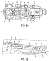
- the switch is shown in the off position in Figs. 8A and 8B , and the on position in Figs. 9A and 9B .
- the yoke 37 When assembled the yoke 37 is inside of the housing 12, and the thumb switch 39 is outside of the housing 12.
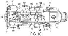
- Fig. 10 shows the yoke passing the peg 120 as the yoke moves between the on and off positions.
- the first and second flexible beams 130, 132 bend outwardly as they pass the post 120. Their flexure insures that the yoke 37 finishes its movement to the desired on position or off position of the switch 34.
Landscapes
- Life Sciences & Earth Sciences (AREA)
- Forests & Forestry (AREA)
- Engineering & Computer Science (AREA)
- Mechanical Engineering (AREA)
- Dry Shavers And Clippers (AREA)
Description
- This invention relates to a hair clipper with a vacuum system, and more particularly, to debris traps for hair clipper vacuum systems, and adjustable air inlets for hair clipper vacuum systems.
- Conventional vacuum systems for hair clippers have a debris trap that catches hair fragments as the hair is cut. However, airflow decreases as debris accumulates in the trap, which reduces airflow and inhibits waste accumulation Thus, there is a need for debris traps that maintain better waste accumulation as the trap fills with debris.
- Hair clippers and trimmers sometime create cut long hair strands. At other times, they create small debris, such as beard stubble. Conventional vacuum systems for hair clippers have a fixed air inlet adjacent the cutting blades to catch all of the debris. However, a large air inlet draws large debris well, but small debris can be lost because negative air pressure at the inlet is relatively low. A small air inlet creates a strong vacuum, which attracts small hair particles, but longer hair can get stuck in the air inlet, because it is small. Accordingly, there is a need for air inlets for vacuum systems for hair clippers that can be adjusted to collect different types of debris well.
- Accordingly, one object of this invention is to provide a hair clipper with a new and improved vacuum system debris trap for hair clippers that maintain better waste accumulation as the trap fills with debris.
- Another object is to provide hair clippers with vacuum systems that collect different types of debris well.
-
US 2006/0230619 A1 discloses a hand-held apparatus for clipping hair including a self-contained vacuum source for collection of hair clippings. The apparatus comprises a housing. An airway extends within the housing from an inlet to an exhaust. A vacuum source is disposed in the airway intermediate the inlet and the exhaust and operates to draw air into the housing through the inlet. A cutting assembly comprising at least one cutting blade is disposed exterior of the airway in spaced relationship with the housing inlet such that hair clippings produced by the cutting assembly are drawn through the housing inlet into the airway. A filter member is disposed in the airway between the inlet and the vacuum source to inhibit hair clippings that have been drawn into the airway from flowing to the vacuum source. - In keeping with this invention, a hair clipper has the features of
claim 1. - Inside the housing, the total air flow is divided into multiple paths, including at least one primary flow path and at least one separate secondary flow path. The housing has at least one air exhaust opening through which the total airflow is released after the air passes the air flow generator.
- A debris trap is located between the air flow generator and the air inlet. The debris trap intersects both the primary air flow path and the secondary air flow path. The primary flow path has an effective primary opening that is larger than an effective secondary opening in the secondary airflow path, which can be one or more actual paths.
- The primary flow path is preferably in a straight line from the air inlet to the air flow generator, which together with the larger primary opening, allows air flow through the first path to be higher than a secondary air flow through the second path before debris accumulates in the debris trap. The primary air flow decreases as debris accumulates in the primary air flow path and the secondary air flow approaches and perhaps exceeds the primary air flow, whereupon some debris accumulates in the secondary airflow path as air is diverted through the secondary airflow path.
- In keeping with the invention, the air inlet adjacent the cutting blades is adjustable to selectively present a small opening for higher air flow and better trapping of small debris, and a larger opening for collecting relatively large debris when needed.
- The above mentioned and other features of this invention and the manner of obtaining them will become more apparent, and the invention itself will be best understood by reference to the following description of an embodiment of the invention taken in conjunction with the accompanying drawings, in which:
-
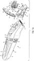
Fig. 1A is an exploded view of an embodiment of a hair clipper according to the present invention; -
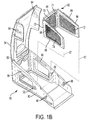
Fig. 1B is another exploded view of part of the hair clipper ofFig. 1A , showing how the debris trap is secured in the debris chamber; -
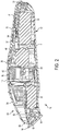
Fig. 2 is an inside view of the hair clipper ofFig. 1 , as assembled; -
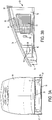
Fig. 3A is a front view of the debris trap in the hair clipper ofFig. 1 , shown with a narrow air inlet; -
Fig. 3B is a side view of the debris trap as shown inFig. 3A ; -
Fig. 4A is front view of the debris trap in the hair clipper ofFig. 1 , shown with a wide air inlet; -
Fig. 4B is a side view of the debris trap as shown inFig. 4A ; -
Fig. 5 is diagram showing air flow in the hair clipper ofFig. 1 when there is no debris in the debris trap; -
Fig. 6 is a diagram showing air flow in the hair clipper ofFig. 1 when some debris has accumulated in the debris trap; -
Fig. 7 is an exploded view of the switch actuator assembly in the hair clipper ofFig. 1 ; -
Fig. 8A is a diagram of a switch actuator assembly in the hair clipper ofFig. 1 , shown in the off position; -
Fig. 8B is a partially cutaway side view of part of the switch actuator assembly ofFig. 8A ; -
Fig. 9A is a diagram of the switch actuator assembly ofFig. 8A in the on position; -
Fig. 9B is a partially cutaway side view of part of the switch actuator assembly ofFig. 8A ; and -
Fig. 10 is a diagram of the switch actuator assembly ofFig. 8A , between the on and off positions. - As seen in
Figs. 1 and2 , ahair clipper 10 has ahousing 12 that includes abottom case 11, atop lid 13 and aswitch panel 15. Thehair clipper 10 also has astationary blade 14 and areciprocating blade 16. Both blades have complimentary rows of cutting teeth at anend 18. Thecutting blades bottom case 11 of thehousing 12 in any suitable manner, such as retaining ribs or screws. The blades are secured outside of the housing. - The
reciprocating blade 16 is driven back and forth by a motor 30 (Fig. 2 ), which is powered by abattery 32 through anelectrical switch 34. A charging port 33 can be provided, as well as anLED 41 to indicate the battery state, power status and the like. - A vacuum system includes another
motor 40 having afan 42 that generates air flow in the housing, as will be described. Themotor 40 is also powered by thebattery 32 through theswitch 34. Theswitch 34 is part of a switch assembly that controls power to themotors actuator 35. Theactuator 35 has ayoke 37 inside thehousing 12 and athumb switch 39 that rests outside of thehousing 12. Theyoke 37 andthumb switch 39 are of one piece construction. The switch assembly also includes theswitch panel 15 that is secured to thebottom case 11 of thehousing 12 using screws in screw studs 17 (Fig. 7 ). - The vacuum system has a
removable debris chamber 50, shown removed and exploded inFig. 1A . Thedebris chamber 50 has a fixedpiece 52 and a hingedportion 54. The hingedportion 54 is secured to the fixedpiece 52 by ahinge 56. When the hingedportion 54 is closed, as inFig. 2 , the fixedpiece 52 and hingedportion 54 form aninlet throat 58 adjacent thecutting blade end 18 for air intake leading into the vacuum system. Rotation of thefan 42 by themotor 40 creates air flow into theintake throat 58, through thedebris chamber 50. The air is released from the hair clipper under pressure created by thefan 42 andmotor 40 through exhaust vents 59. - The
debris chamber 50 has adebris trap 60 that accumulates debris in thechamber 50 and prevents the debris from reaching the motor and exhaust. Thetrap 60 has aframe 62 with threesides side 64 has anedge 71 adjacent theside 66, and anedge 73 adjacent theside 68. An opening is provided in eachside mesh screens sides respective screens side 64 and itsscreen 70, and parallel to each other. - The debris on
chamber 50 has a pair ofrails 80 that slide under a corresponding pair of rails ontop lid 82 for mating thedebris chamber 50 with thehousing top lid 13.Bumps 83 pass over raisedportions 90 in thetop lid 13 to further secure thedebris chamber 50. The rails also facilitate removal of thedebris chamber 50 for cleaning. The walls of thechamber 50 are appropriately flexible for adequate securement and removal without excessive effort. - The
trap 60 is secured in thedebris chamber 50 by placing it inside of L-shapedgrooves 85 in thechamber 50 and engaging protrusions 84 (in thesides 66, 68) over openings 86 (in the chamber 50).Dash lines 87 indicate how thetrap 60 is installed. - The hinged
portion 54 and fixedpiece 52 share thehinge 56 on one end, and a set of bumps 94 (on the hinged portion 54) and holes 96 (on the fixed piece) on the other end. Thethroat 58 is generally formed alongedges 61, outlined in bold lines inFigs. 3A-3B . The size of thethroat 58 can be small, as seen inFig. 3A , by engaging thebumps 94 and holes 96 in the manner shown inFig. 3B . Thethroat 58 can be made larger (Fig. 4A ) by lifting the hingedportion 54 and engaging thebumps 94 and holes 96 as shown inFig. 4B . In this manner, the size of thethroat 58 can be adjusted to better capture small debris (in the position shown inFig. 3A ) or large debris (in the position shown inFig. 4A ). - Air flow in the vacuum system will be described primarily in connection with
Figs. 5 and 6 . Thefan 42 creates a vacuum at theend 18 by drawing air into thechamber 50 through theintake throat 58. The total air flow into thedebris chamber 50 is indicated byarrows 100. A primary airflow path (arrows 102) goes through thescreen 70, and secondary air flow paths indicated byarrows screens screen 70. The secondary air flows pass through thescreens openings 108 between the outside of thechamber 50 and thehousing top lid 13. Theopenings 108 restrict the secondary air flows, as will be described. - In
Fig. 5 , there is no debris in thechamber 50, so the primary air flow is stronger than the secondary air flow and incoming debris tends to accumulate in the primaryair flow path 102. - Referring now to
Fig. 6 , asdebris 106 accumulates, thedebris 106 decreases theprimary air flow 102, which increases thesecondary air flow screens debris 106 accumulates adjacent thescreen 70. - The
switch panel 15 has anopening 126, seen inFig. 7 . To assemble the switch assembly, theyoke 37 is inserted through theopening 126 until thethumb switch 39 reaches a switch landing 128 on theswitch panel 15. - Referring now to
Figs. 8A and 8B , theswitch panel 15 has apeg 120, a pair of opposedwalls 122 and a pair of projectingbarbs 124. Thebarbs 124 are flexible, and secure theyoke 37 when it is pushed between thebarbs 124. Apost 125 provides movement limits for theswitch actuator 35. - The
yoke 37 surrounds thepeg 120 with a first flexible beam130 and a secondflexible beam 132. Thebeams switch actuator 35 hasbarbs 142 that engage thewalls 122 in theswitch panel 15 to prevent theswitch actuator 35 from falling out. Thebarbs 124 engage theend 136 of theswitch actuator 35. Theswitch 34 fits in anopening 145 in theswitch actuator 35, and thepost 125 fits in anopening 137. - The switch is shown in the off position in
Figs. 8A and 8B , and the on position inFigs. 9A and 9B . When assembled theyoke 37 is inside of thehousing 12, and thethumb switch 39 is outside of thehousing 12. -
Fig. 10 shows the yoke passing thepeg 120 as the yoke moves between the on and off positions. The first and secondflexible beams post 120. Their flexure insures that theyoke 37 finishes its movement to the desired on position or off position of theswitch 34. - While the principles of the invention have been described above in connection with specific apparatus and applications, it is to be understood that this description is made only by way of example and not as a limitation on the scope of the invention.
Claims (8)
- A hair clipper (10) having a housing (12), cutting blades (14), (16) secured to the housing (12) outside of the housing (12), and a vacuum system, the vacuum system comprising
an air flow generator (42) in the housing (12),
an air inlet (58) adjacent the cutting blades (14), (16) leading inside the housing (12), the air flow generator (42) creating a total air flow that draws air from the cutting blades (14), (16) into the housing (12),
an air exhaust (59) in the housing (12) that releases the total air flow under pressure created by the air flow generator (42), and
a debris chamber (50) between the air flow generator (42) and the air inlet (58), the debris chamber (50) having a primary air flow path (102) and at least one secondary air flow path (104, 105),
wherein a primary air flow through the primary air flow path (102) is higher than a secondary air flow through the secondary air flow path (104, 105) before debris accumulates in the debris chamber (50), the primary air flow decreasing as debris accumulates in the primary air flow path (102), whereupon some debris accumulates in the secondary air flow path (104, 105) as air is diverted through the secondary air flow path (104, 105), and
wherein the debris chamber (50) has a hinged portion (54) and a fixed piece (52) that share a hinge (56) on one end and form the air inlet (58) on the other end, the hinged portion (54) having a set of bumps (94) on the other end and the fixed piece (52) having a set of corresponding holes (96) on the other end,
whereby the size of the air inlet (58) is adjustable, the size of the air inlet (58) being determined by inserting selected bumps (94) into selected holes (96). - The hair clipper (10) of claim 1 wherein the debris chamber (50) includes a first screen (70) perpendicular to the primary air flow path (102), the primary air flow passing through the first screen (70),
the first screen (70) having a first edge (71) and a second edge (73),
a second screen (72) adjacent the first edge (71) and perpendicular to the first screen (70), and
a third screen (74) adjacent the second edge (73) and perpendicular to the first screen (70),
the secondary air flow being divided between the second and third screens (72), (74) and passing through the second and third screens (72, 74). - The hair clipper (10) of claim 1 or 2, further comprising:a switch assembly for controlling power to the air flow generator (42); the switch assembly havingan electrical switch (34) secured to the housing (12);a switch panel (15) forming part of the housing (12); anda switch actuator (35) that controls the electrical switch (34),the switch actuator (35) having a yoke (37) inside the housing (12) and a thumb switch (39) outside of the housing (12), the yoke (37) and the thumb switch (39) being secured to each other through an opening (126) in the switch panel (15),the switch actuator (35) further having an opening (137) for insertion of the electrical switch (34).
- The hair clipper (10) of any one of the preceding claims, wherein an opening at the air inlet (58) is adjustable.
- The hair clipper (10) of any one of the preceding claims, wherein the housing (12) includes a bottom case (11), a top lid (13) and a switch panel (15).
- The hair clipper (10) of any one of the preceding claims, wherein the debris chamber (50) includes the fixed piece (52) and the hinged portion (54), the hinged portion (54) being secured to the fixed piece (52) by the hinge (56), such that when the hinged portion (54) is closed, the fixed piece (52) and the hinged portion (54) form an inlet throat adjacent the cutting blades (14, 16) for air intake into the vacuum system.
- The hair clipper (10) of any one of the preceding claims, wherein the debris chamber (50) has a debris trap (60) that accumulates debris in the debris chamber (50), the debris trap (60) having a frame (62) with a first side (64) having a first opening and a first screen (70) in the first opening, a second side (66) having a second opening and a second screen (72) in the second opening, and a third side (68) having a third opening and a third screen (74) in the third opening.
- The hair clipper (10) of claim 7, wherein the second and third sides (66, 68) are perpendicular to the first side (64), the second and third sides (66, 68) extend from opposing edges (71, 73) of the first side (64), and the second and third sides (66, 68) are parallel to each other.
Applications Claiming Priority (1)
| Application Number | Priority Date | Filing Date | Title |
|---|---|---|---|
| US15/474,742 US10279493B2 (en) | 2017-03-30 | 2017-03-30 | Vacuum systems for hair clippers |
Publications (2)
| Publication Number | Publication Date |
|---|---|
| EP3385042A1 EP3385042A1 (en) | 2018-10-10 |
| EP3385042B1 true EP3385042B1 (en) | 2019-10-30 |
Family
ID=61827591
Family Applications (1)
| Application Number | Title | Priority Date | Filing Date |
|---|---|---|---|
| EP18164221.6A Active EP3385042B1 (en) | 2017-03-30 | 2018-03-27 | Vacuum systems for hair clippers |
Country Status (4)
| Country | Link |
|---|---|
| US (1) | US10279493B2 (en) |
| EP (1) | EP3385042B1 (en) |
| CN (1) | CN108687806B (en) |
| AU (1) | AU2018201745B2 (en) |
Families Citing this family (10)
| Publication number | Priority date | Publication date | Assignee | Title |
|---|---|---|---|---|
| TR201906686T4 (en) * | 2015-01-28 | 2019-05-21 | Koninklijke Philips Nv | Hair clipper. |
| CN210968984U (en) * | 2018-05-02 | 2020-07-10 | 皇家飞利浦有限公司 | Hair cutting system and hair collector |
| IT201800002787U1 (en) * | 2018-06-18 | 2019-12-18 | Salvatore Morra | HAIR CUTTER |
| EP3666478A1 (en) * | 2018-12-12 | 2020-06-17 | Koninklijke Philips N.V. | Hair collector for a hair cutting appliance having a cutting element |
| IT201900023385A1 (en) * | 2019-12-09 | 2021-06-09 | Massimo Bitocchi | PERFECTED ELECTRIC HAIR CUTTER |
| IT201900023376A1 (en) * | 2019-12-09 | 2021-06-09 | Massimo Bitocchi | PERFECTED ELECTRIC HAIR CUTTER |
| USD992837S1 (en) * | 2020-08-21 | 2023-07-18 | Shenzhen Dogcare Innovation & Technology Co., Ltd. | Animal hair clipper |
| USD976491S1 (en) * | 2021-08-12 | 2023-01-24 | Shenzhen Joyu Appliance Co., Ltd. | Hair clipper |
| CN217891036U (en) * | 2022-08-15 | 2022-11-25 | 武汉神宝宠物用品有限公司 | An electric clipper with hair-absorbing function |
| USD981043S1 (en) | 2022-12-12 | 2023-03-14 | E. Mishan & Sons, Inc. | Shaver |
Family Cites Families (48)
| Publication number | Priority date | Publication date | Assignee | Title |
|---|---|---|---|---|
| US1572644A (en) | 1924-03-24 | 1926-02-09 | William W Farnsworth | Hair cutter |
| US2323046A (en) | 1942-03-16 | 1943-06-29 | Francis R Jenkins | Hair clipper |
| GB714863A (en) | 1951-12-03 | 1954-09-01 | Albin Kenneth Peterson | Mechanical dry shaver |
| US2802260A (en) | 1955-12-30 | 1957-08-13 | Charles S Allen | Dry shaver with rotary cutting blades and suction fan |
| US2916821A (en) | 1958-10-08 | 1959-12-15 | John M Witmer | Rotary dry shaver with waste collecting means |
| US2946123A (en) | 1959-02-27 | 1960-07-26 | Murel B Bray | Combination hair clipper |
| US3035346A (en) | 1959-10-02 | 1962-05-22 | William A Campbell | Tool for hair-cutting and other purposes |
| US3369294A (en) * | 1965-10-23 | 1968-02-20 | Timac Inc | Power driven wet shaver |
| US3604112A (en) | 1969-04-29 | 1971-09-14 | Krishin H Bhavnani | Method and apparatus for hair cutting |
| US3611566A (en) | 1969-07-01 | 1971-10-12 | William J Brennan | Electric shaver with vacuum collector |
| US3699652A (en) | 1971-11-09 | 1972-10-24 | Kenneth D Deverman | Rotary hair clipper |
| IT7854019V0 (en) | 1978-01-04 | 1978-12-29 | Silvano Vacilotto | ION VACUUM MACHINE FOR HAIR CUT |
| US4314405A (en) | 1980-04-24 | 1982-02-09 | Park Du P | Hair cutting device |
| JPS57206477A (en) | 1981-06-15 | 1982-12-17 | Matsushita Electric Works Ltd | Electric razor |
| DE3330741A1 (en) | 1983-08-26 | 1985-03-07 | Reinhard 7500 Karlsruhe Steil | Electric shaver |
| DE3477356D1 (en) | 1983-12-15 | 1989-04-27 | Hitachi Maxell | Electric hair clipper |
| US4622745A (en) | 1984-09-28 | 1986-11-18 | Wahl Clipper Corporation | Hair trimming apparatus |
| USD294407S (en) | 1985-08-19 | 1988-02-23 | Braun Aktiengesellschaft | Hair clipper with cutting cap |
| US5050305A (en) | 1985-09-13 | 1991-09-24 | Remington Products, Inc. | Hair trimmer with comb attachment |
| JPS62114588A (en) | 1985-11-14 | 1987-05-26 | 松下電工株式会社 | Hairclippers |
| JPH035899A (en) | 1989-06-01 | 1991-01-11 | Olympus Optical Co Ltd | Warning issuance recognition supporting device |
| US5075971A (en) | 1990-07-17 | 1991-12-31 | Wahl Clipper Corporation | Methods and apparatus for trimming hair and disposing of hair clippings |
| US5012576A (en) | 1990-07-18 | 1991-05-07 | Johannesson Jimmie R | Personal hair trimmer |
| US5084974A (en) | 1991-01-22 | 1992-02-04 | Andis Company | Clipper with lever actuated adjustable comb |
| JPH0751472A (en) | 1993-08-11 | 1995-02-28 | Toshiomi Suzuki | Electric shaver integrated with dust suction device |
| DE9404125U1 (en) | 1994-03-11 | 1994-05-26 | Hofer, Egbert Otto Dietrich, 87719 Mindelheim | Shaver with a suction device |
| IL109882A0 (en) | 1994-06-02 | 1994-10-07 | Kelman Elliot | Hair cutting apparatus |
| US5724736A (en) | 1996-11-05 | 1998-03-10 | Smith; James E. | Hair cutting device |
| JPH1176646A (en) | 1997-09-10 | 1999-03-23 | Hisakazu Tsuji | Dust sucking type electric razor |
| US5970616A (en) * | 1997-12-22 | 1999-10-26 | Wahl Clipper Corporation | Hair trimmer with lighted rotating head |
| JP2000061174A (en) | 1998-08-19 | 2000-02-29 | Yuji Iso | Electric shaver |
| JP3005899B1 (en) | 1998-10-14 | 2000-02-07 | 清水市農業協同組合 | Beverage production equipment |
| US6261161B1 (en) | 1999-01-06 | 2001-07-17 | Premark Feg L.L.C. | Sharpener assembly for a food slicer and related method |
| GB9916759D0 (en) * | 1999-07-17 | 1999-09-15 | Black & Decker Inc | Improvements in vacuum cleaners |
| USD472674S1 (en) | 2000-12-14 | 2003-04-01 | Wahl Clipper Corporation | Hair trimmer with vacuum |
| US6739053B2 (en) * | 2000-12-14 | 2004-05-25 | Wahl Clipper Corporation | Hair clipping device with internal vacuum |
| US6684511B2 (en) | 2000-12-14 | 2004-02-03 | Wahl Clipper Corporation | Hair clipping device with rotating bladeset having multiple cutting edges |
| US6665938B2 (en) | 2000-12-14 | 2003-12-23 | Wahl Clipper Corporation | Hair clipping device with adjustable deflecting comb assembly |
| US6978547B2 (en) | 2001-02-14 | 2005-12-27 | Degregorio Jr Dennis P | Beard trimmer with internal vacuum |
| KR100437116B1 (en) * | 2002-05-22 | 2004-06-23 | 삼성광주전자 주식회사 | Vacuum cleaner |
| WO2004002690A1 (en) | 2002-06-26 | 2004-01-08 | Koninklijke Philips Electronics N.V. | Hair-cutting apparatus comprising a hair suction device |
| US20060162516A1 (en) | 2002-10-31 | 2006-07-27 | Andis Company | Hair trimmer |
| US20060042036A1 (en) * | 2004-08-31 | 2006-03-02 | Rovcal, Inc. | Electric shaver and cleaning system therefor |
| US20060230619A1 (en) * | 2005-04-18 | 2006-10-19 | Rovcal, Inc. | Hair clipper with vacuum collection system |
| US8484853B1 (en) * | 2005-08-29 | 2013-07-16 | Kim Laube | Hair cutting device with vacuum hair collection system |
| US8857011B2 (en) | 2009-01-16 | 2014-10-14 | Robert W. Casper | Pet vacuum cleaner |
| CN105980115A (en) * | 2014-02-13 | 2016-09-28 | 品谱公司 | Hair trimmer with vacuum collection system |
| CN205380696U (en) * | 2015-12-28 | 2016-07-13 | 东莞市康发特塑胶制品有限公司 | Detachable automatic vacuum electric hair clipper |
-
2017
- 2017-03-30 US US15/474,742 patent/US10279493B2/en active Active
-
2018
- 2018-03-09 AU AU2018201745A patent/AU2018201745B2/en not_active Ceased
- 2018-03-27 EP EP18164221.6A patent/EP3385042B1/en active Active
- 2018-03-29 CN CN201810272149.3A patent/CN108687806B/en active Active
Non-Patent Citations (1)
| Title |
|---|
| None * |
Also Published As
| Publication number | Publication date |
|---|---|
| CN108687806A (en) | 2018-10-23 |
| US10279493B2 (en) | 2019-05-07 |
| EP3385042A1 (en) | 2018-10-10 |
| US20180281214A1 (en) | 2018-10-04 |
| CN108687806B (en) | 2022-03-25 |
| AU2018201745A1 (en) | 2018-10-18 |
| AU2018201745B2 (en) | 2019-08-01 |
Similar Documents
| Publication | Publication Date | Title |
|---|---|---|
| US10279493B2 (en) | Vacuum systems for hair clippers | |
| US6978547B2 (en) | Beard trimmer with internal vacuum | |
| US10458437B2 (en) | Air blower | |
| US6739053B2 (en) | Hair clipping device with internal vacuum | |
| CN100418710C (en) | nose hair knife | |
| CN107206603B (en) | hair clipper device | |
| US20180345510A1 (en) | Trimmer with hair collector | |
| KR101189809B1 (en) | Apparatus for cleaning dust and killing insects | |
| JP5193959B2 (en) | Insect trapping device | |
| US20060179657A1 (en) | Shaver with flushable hair chamber | |
| GB2410457A (en) | Hair trimming mechanism incorporating an airflow system | |
| RU2389601C1 (en) | Machine for hair cutting | |
| JP3979341B2 (en) | Ventilation equipment | |
| US7975385B2 (en) | Hair-cutting apparatus comprising means for preventing cut hair from flying off | |
| KR101127975B1 (en) | Apparatus for Controlling Mosquito | |
| US20240308108A1 (en) | Electrical work apparatus | |
| EP1775078A1 (en) | Hair clipper | |
| EP1491126A2 (en) | Vacuum cleaner | |
| JPWO2018230007A1 (en) | Blower | |
| CN105492836B (en) | Air conditioner | |
| KR102605946B1 (en) | Filter mounting structure for air conditioner | |
| KR200421848Y1 (en) | Air Conditioning Air Filter | |
| KR0175862B1 (en) | In-door machine of airconditioner | |
| KR20150041248A (en) | Insect trap having cleaning unit | |
| WO2023105998A1 (en) | Blower device |
Legal Events
| Date | Code | Title | Description |
|---|---|---|---|
| PUAI | Public reference made under article 153(3) epc to a published international application that has entered the european phase |
Free format text: ORIGINAL CODE: 0009012 |
|
| STAA | Information on the status of an ep patent application or granted ep patent |
Free format text: STATUS: THE APPLICATION HAS BEEN PUBLISHED |
|
| AK | Designated contracting states |
Kind code of ref document: A1 Designated state(s): AL AT BE BG CH CY CZ DE DK EE ES FI FR GB GR HR HU IE IS IT LI LT LU LV MC MK MT NL NO PL PT RO RS SE SI SK SM TR |
|
| AX | Request for extension of the european patent |
Extension state: BA ME |
|
| STAA | Information on the status of an ep patent application or granted ep patent |
Free format text: STATUS: REQUEST FOR EXAMINATION WAS MADE |
|
| 17P | Request for examination filed |
Effective date: 20190213 |
|
| RBV | Designated contracting states (corrected) |
Designated state(s): AL AT BE BG CH CY CZ DE DK EE ES FI FR GB GR HR HU IE IS IT LI LT LU LV MC MK MT NL NO PL PT RO RS SE SI SK SM TR |
|
| GRAP | Despatch of communication of intention to grant a patent |
Free format text: ORIGINAL CODE: EPIDOSNIGR1 |
|
| STAA | Information on the status of an ep patent application or granted ep patent |
Free format text: STATUS: GRANT OF PATENT IS INTENDED |
|
| RIC1 | Information provided on ipc code assigned before grant |
Ipc: B26B 19/44 20060101AFI20190506BHEP |
|
| INTG | Intention to grant announced |
Effective date: 20190612 |
|
| GRAS | Grant fee paid |
Free format text: ORIGINAL CODE: EPIDOSNIGR3 |
|
| GRAA | (expected) grant |
Free format text: ORIGINAL CODE: 0009210 |
|
| STAA | Information on the status of an ep patent application or granted ep patent |
Free format text: STATUS: THE PATENT HAS BEEN GRANTED |
|
| AK | Designated contracting states |
Kind code of ref document: B1 Designated state(s): AL AT BE BG CH CY CZ DE DK EE ES FI FR GB GR HR HU IE IS IT LI LT LU LV MC MK MT NL NO PL PT RO RS SE SI SK SM TR |
|
| REG | Reference to a national code |
Ref country code: GB Ref legal event code: FG4D |
|
| REG | Reference to a national code |
Ref country code: CH Ref legal event code: EP |
|
| REG | Reference to a national code |
Ref country code: AT Ref legal event code: REF Ref document number: 1195636 Country of ref document: AT Kind code of ref document: T Effective date: 20191115 |
|
| REG | Reference to a national code |
Ref country code: DE Ref legal event code: R096 Ref document number: 602018001010 Country of ref document: DE |
|
| REG | Reference to a national code |
Ref country code: IE Ref legal event code: FG4D |
|
| REG | Reference to a national code |
Ref country code: NL Ref legal event code: FP |
|
| REG | Reference to a national code |
Ref country code: LT Ref legal event code: MG4D |
|
| PG25 | Lapsed in a contracting state [announced via postgrant information from national office to epo] |
Ref country code: PT Free format text: LAPSE BECAUSE OF FAILURE TO SUBMIT A TRANSLATION OF THE DESCRIPTION OR TO PAY THE FEE WITHIN THE PRESCRIBED TIME-LIMIT Effective date: 20200302 Ref country code: LT Free format text: LAPSE BECAUSE OF FAILURE TO SUBMIT A TRANSLATION OF THE DESCRIPTION OR TO PAY THE FEE WITHIN THE PRESCRIBED TIME-LIMIT Effective date: 20191030 Ref country code: NO Free format text: LAPSE BECAUSE OF FAILURE TO SUBMIT A TRANSLATION OF THE DESCRIPTION OR TO PAY THE FEE WITHIN THE PRESCRIBED TIME-LIMIT Effective date: 20200130 Ref country code: FI Free format text: LAPSE BECAUSE OF FAILURE TO SUBMIT A TRANSLATION OF THE DESCRIPTION OR TO PAY THE FEE WITHIN THE PRESCRIBED TIME-LIMIT Effective date: 20191030 Ref country code: BG Free format text: LAPSE BECAUSE OF FAILURE TO SUBMIT A TRANSLATION OF THE DESCRIPTION OR TO PAY THE FEE WITHIN THE PRESCRIBED TIME-LIMIT Effective date: 20200130 Ref country code: GR Free format text: LAPSE BECAUSE OF FAILURE TO SUBMIT A TRANSLATION OF THE DESCRIPTION OR TO PAY THE FEE WITHIN THE PRESCRIBED TIME-LIMIT Effective date: 20200131 Ref country code: PL Free format text: LAPSE BECAUSE OF FAILURE TO SUBMIT A TRANSLATION OF THE DESCRIPTION OR TO PAY THE FEE WITHIN THE PRESCRIBED TIME-LIMIT Effective date: 20191030 Ref country code: LV Free format text: LAPSE BECAUSE OF FAILURE TO SUBMIT A TRANSLATION OF THE DESCRIPTION OR TO PAY THE FEE WITHIN THE PRESCRIBED TIME-LIMIT Effective date: 20191030 Ref country code: SE Free format text: LAPSE BECAUSE OF FAILURE TO SUBMIT A TRANSLATION OF THE DESCRIPTION OR TO PAY THE FEE WITHIN THE PRESCRIBED TIME-LIMIT Effective date: 20191030 |
|
| PG25 | Lapsed in a contracting state [announced via postgrant information from national office to epo] |
Ref country code: HR Free format text: LAPSE BECAUSE OF FAILURE TO SUBMIT A TRANSLATION OF THE DESCRIPTION OR TO PAY THE FEE WITHIN THE PRESCRIBED TIME-LIMIT Effective date: 20191030 Ref country code: RS Free format text: LAPSE BECAUSE OF FAILURE TO SUBMIT A TRANSLATION OF THE DESCRIPTION OR TO PAY THE FEE WITHIN THE PRESCRIBED TIME-LIMIT Effective date: 20191030 Ref country code: IS Free format text: LAPSE BECAUSE OF FAILURE TO SUBMIT A TRANSLATION OF THE DESCRIPTION OR TO PAY THE FEE WITHIN THE PRESCRIBED TIME-LIMIT Effective date: 20200229 |
|
| PG25 | Lapsed in a contracting state [announced via postgrant information from national office to epo] |
Ref country code: AL Free format text: LAPSE BECAUSE OF FAILURE TO SUBMIT A TRANSLATION OF THE DESCRIPTION OR TO PAY THE FEE WITHIN THE PRESCRIBED TIME-LIMIT Effective date: 20191030 |
|
| PG25 | Lapsed in a contracting state [announced via postgrant information from national office to epo] |
Ref country code: RO Free format text: LAPSE BECAUSE OF FAILURE TO SUBMIT A TRANSLATION OF THE DESCRIPTION OR TO PAY THE FEE WITHIN THE PRESCRIBED TIME-LIMIT Effective date: 20191030 Ref country code: CZ Free format text: LAPSE BECAUSE OF FAILURE TO SUBMIT A TRANSLATION OF THE DESCRIPTION OR TO PAY THE FEE WITHIN THE PRESCRIBED TIME-LIMIT Effective date: 20191030 Ref country code: DK Free format text: LAPSE BECAUSE OF FAILURE TO SUBMIT A TRANSLATION OF THE DESCRIPTION OR TO PAY THE FEE WITHIN THE PRESCRIBED TIME-LIMIT Effective date: 20191030 Ref country code: ES Free format text: LAPSE BECAUSE OF FAILURE TO SUBMIT A TRANSLATION OF THE DESCRIPTION OR TO PAY THE FEE WITHIN THE PRESCRIBED TIME-LIMIT Effective date: 20191030 Ref country code: EE Free format text: LAPSE BECAUSE OF FAILURE TO SUBMIT A TRANSLATION OF THE DESCRIPTION OR TO PAY THE FEE WITHIN THE PRESCRIBED TIME-LIMIT Effective date: 20191030 |
|
| REG | Reference to a national code |
Ref country code: DE Ref legal event code: R097 Ref document number: 602018001010 Country of ref document: DE |
|
| REG | Reference to a national code |
Ref country code: AT Ref legal event code: MK05 Ref document number: 1195636 Country of ref document: AT Kind code of ref document: T Effective date: 20191030 |
|
| PG25 | Lapsed in a contracting state [announced via postgrant information from national office to epo] |
Ref country code: SK Free format text: LAPSE BECAUSE OF FAILURE TO SUBMIT A TRANSLATION OF THE DESCRIPTION OR TO PAY THE FEE WITHIN THE PRESCRIBED TIME-LIMIT Effective date: 20191030 Ref country code: IT Free format text: LAPSE BECAUSE OF FAILURE TO SUBMIT A TRANSLATION OF THE DESCRIPTION OR TO PAY THE FEE WITHIN THE PRESCRIBED TIME-LIMIT Effective date: 20191030 Ref country code: SM Free format text: LAPSE BECAUSE OF FAILURE TO SUBMIT A TRANSLATION OF THE DESCRIPTION OR TO PAY THE FEE WITHIN THE PRESCRIBED TIME-LIMIT Effective date: 20191030 |
|
| PLBE | No opposition filed within time limit |
Free format text: ORIGINAL CODE: 0009261 |
|
| STAA | Information on the status of an ep patent application or granted ep patent |
Free format text: STATUS: NO OPPOSITION FILED WITHIN TIME LIMIT |
|
| 26N | No opposition filed |
Effective date: 20200731 |
|
| PG25 | Lapsed in a contracting state [announced via postgrant information from national office to epo] |
Ref country code: MC Free format text: LAPSE BECAUSE OF FAILURE TO SUBMIT A TRANSLATION OF THE DESCRIPTION OR TO PAY THE FEE WITHIN THE PRESCRIBED TIME-LIMIT Effective date: 20191030 |
|
| PG25 | Lapsed in a contracting state [announced via postgrant information from national office to epo] |
Ref country code: SI Free format text: LAPSE BECAUSE OF FAILURE TO SUBMIT A TRANSLATION OF THE DESCRIPTION OR TO PAY THE FEE WITHIN THE PRESCRIBED TIME-LIMIT Effective date: 20191030 Ref country code: AT Free format text: LAPSE BECAUSE OF FAILURE TO SUBMIT A TRANSLATION OF THE DESCRIPTION OR TO PAY THE FEE WITHIN THE PRESCRIBED TIME-LIMIT Effective date: 20191030 |
|
| REG | Reference to a national code |
Ref country code: BE Ref legal event code: MM Effective date: 20200331 |
|
| PG25 | Lapsed in a contracting state [announced via postgrant information from national office to epo] |
Ref country code: LU Free format text: LAPSE BECAUSE OF NON-PAYMENT OF DUE FEES Effective date: 20200327 |
|
| PG25 | Lapsed in a contracting state [announced via postgrant information from national office to epo] |
Ref country code: IE Free format text: LAPSE BECAUSE OF NON-PAYMENT OF DUE FEES Effective date: 20200327 Ref country code: FR Free format text: LAPSE BECAUSE OF NON-PAYMENT OF DUE FEES Effective date: 20200331 |
|
| PG25 | Lapsed in a contracting state [announced via postgrant information from national office to epo] |
Ref country code: BE Free format text: LAPSE BECAUSE OF NON-PAYMENT OF DUE FEES Effective date: 20200331 |
|
| REG | Reference to a national code |
Ref country code: CH Ref legal event code: PL |
|
| PG25 | Lapsed in a contracting state [announced via postgrant information from national office to epo] |
Ref country code: CH Free format text: LAPSE BECAUSE OF NON-PAYMENT OF DUE FEES Effective date: 20210331 Ref country code: LI Free format text: LAPSE BECAUSE OF NON-PAYMENT OF DUE FEES Effective date: 20210331 |
|
| PG25 | Lapsed in a contracting state [announced via postgrant information from national office to epo] |
Ref country code: TR Free format text: LAPSE BECAUSE OF FAILURE TO SUBMIT A TRANSLATION OF THE DESCRIPTION OR TO PAY THE FEE WITHIN THE PRESCRIBED TIME-LIMIT Effective date: 20191030 Ref country code: MT Free format text: LAPSE BECAUSE OF FAILURE TO SUBMIT A TRANSLATION OF THE DESCRIPTION OR TO PAY THE FEE WITHIN THE PRESCRIBED TIME-LIMIT Effective date: 20191030 Ref country code: CY Free format text: LAPSE BECAUSE OF FAILURE TO SUBMIT A TRANSLATION OF THE DESCRIPTION OR TO PAY THE FEE WITHIN THE PRESCRIBED TIME-LIMIT Effective date: 20191030 |
|
| PG25 | Lapsed in a contracting state [announced via postgrant information from national office to epo] |
Ref country code: MK Free format text: LAPSE BECAUSE OF FAILURE TO SUBMIT A TRANSLATION OF THE DESCRIPTION OR TO PAY THE FEE WITHIN THE PRESCRIBED TIME-LIMIT Effective date: 20191030 |
|
| PGFP | Annual fee paid to national office [announced via postgrant information from national office to epo] |
Ref country code: NL Payment date: 20240220 Year of fee payment: 7 |
|
| P01 | Opt-out of the competence of the unified patent court (upc) registered |
Free format text: CASE NUMBER: UPC_APP_119251/2023 Effective date: 20230510 |
|
| REG | Reference to a national code |
Ref country code: NL Ref legal event code: MM Effective date: 20250401 |
|
| PG25 | Lapsed in a contracting state [announced via postgrant information from national office to epo] |
Ref country code: NL Free format text: LAPSE BECAUSE OF NON-PAYMENT OF DUE FEES Effective date: 20250401 |
|
| PGFP | Annual fee paid to national office [announced via postgrant information from national office to epo] |
Ref country code: GB Payment date: 20260220 Year of fee payment: 9 |
|
| PGFP | Annual fee paid to national office [announced via postgrant information from national office to epo] |
Ref country code: DE Payment date: 20260219 Year of fee payment: 9 |