EP3384335B1 - Coextruded jacket for flame retardant fiber optic cables - Google Patents
Coextruded jacket for flame retardant fiber optic cables Download PDFInfo
- Publication number
- EP3384335B1 EP3384335B1 EP16790814.4A EP16790814A EP3384335B1 EP 3384335 B1 EP3384335 B1 EP 3384335B1 EP 16790814 A EP16790814 A EP 16790814A EP 3384335 B1 EP3384335 B1 EP 3384335B1
- Authority
- EP
- European Patent Office
- Prior art keywords
- jacket
- outer layer
- fiber optic
- flame retardant
- cable
- Prior art date
- Legal status (The legal status is an assumption and is not a legal conclusion. Google has not performed a legal analysis and makes no representation as to the accuracy of the status listed.)
- Active
Links
- 239000003063 flame retardant Substances 0.000 title claims description 44
- RNFJDJUURJAICM-UHFFFAOYSA-N 2,2,4,4,6,6-hexaphenoxy-1,3,5-triaza-2$l^{5},4$l^{5},6$l^{5}-triphosphacyclohexa-1,3,5-triene Chemical compound N=1P(OC=2C=CC=CC=2)(OC=2C=CC=CC=2)=NP(OC=2C=CC=CC=2)(OC=2C=CC=CC=2)=NP=1(OC=1C=CC=CC=1)OC1=CC=CC=C1 RNFJDJUURJAICM-UHFFFAOYSA-N 0.000 title claims description 41
- 239000000835 fiber Substances 0.000 title claims description 28
- 239000000463 material Substances 0.000 claims description 65
- 239000013307 optical fiber Substances 0.000 claims description 36
- 238000009434 installation Methods 0.000 claims description 14
- 238000004519 manufacturing process Methods 0.000 claims description 12
- 238000000034 method Methods 0.000 claims description 12
- 239000000945 filler Substances 0.000 claims description 8
- 239000000779 smoke Substances 0.000 claims description 8
- 229910052736 halogen Inorganic materials 0.000 claims description 6
- 150000002367 halogens Chemical class 0.000 claims description 5
- WNROFYMDJYEPJX-UHFFFAOYSA-K aluminium hydroxide Chemical compound [OH-].[OH-].[OH-].[Al+3] WNROFYMDJYEPJX-UHFFFAOYSA-K 0.000 claims description 3
- VTHJTEIRLNZDEV-UHFFFAOYSA-L magnesium dihydroxide Chemical compound [OH-].[OH-].[Mg+2] VTHJTEIRLNZDEV-UHFFFAOYSA-L 0.000 claims description 3
- 239000000347 magnesium hydroxide Substances 0.000 claims description 3
- 229910001862 magnesium hydroxide Inorganic materials 0.000 claims description 3
- 239000010409 thin film Substances 0.000 claims 3
- 239000010408 film Substances 0.000 claims 1
- 239000010410 layer Substances 0.000 description 73
- 239000002245 particle Substances 0.000 description 37
- 229920000642 polymer Polymers 0.000 description 25
- 239000000843 powder Substances 0.000 description 19
- 239000011230 binding agent Substances 0.000 description 13
- 239000002250 absorbent Substances 0.000 description 12
- -1 polyethylene Polymers 0.000 description 10
- 239000004698 Polyethylene Substances 0.000 description 9
- 229920000573 polyethylene Polymers 0.000 description 9
- 238000012360 testing method Methods 0.000 description 9
- 238000007664 blowing Methods 0.000 description 8
- 238000001125 extrusion Methods 0.000 description 7
- 150000001875 compounds Chemical class 0.000 description 6
- 238000005336 cracking Methods 0.000 description 6
- XLYOFNOQVPJJNP-UHFFFAOYSA-N water Substances O XLYOFNOQVPJJNP-UHFFFAOYSA-N 0.000 description 5
- 239000004760 aramid Substances 0.000 description 4
- 229920003235 aromatic polyamide Polymers 0.000 description 4
- 230000008901 benefit Effects 0.000 description 4
- 230000000903 blocking effect Effects 0.000 description 4
- 230000008878 coupling Effects 0.000 description 4
- 238000010168 coupling process Methods 0.000 description 4
- 238000005859 coupling reaction Methods 0.000 description 4
- 150000004677 hydrates Chemical class 0.000 description 4
- 239000000203 mixture Substances 0.000 description 4
- 230000008569 process Effects 0.000 description 4
- OKTJSMMVPCPJKN-UHFFFAOYSA-N Carbon Chemical compound [C] OKTJSMMVPCPJKN-UHFFFAOYSA-N 0.000 description 3
- 229910000831 Steel Inorganic materials 0.000 description 3
- 238000005253 cladding Methods 0.000 description 3
- 230000000694 effects Effects 0.000 description 3
- 238000005516 engineering process Methods 0.000 description 3
- 230000009970 fire resistant effect Effects 0.000 description 3
- 239000010439 graphite Substances 0.000 description 3
- 229910002804 graphite Inorganic materials 0.000 description 3
- 239000010959 steel Substances 0.000 description 3
- 239000000126 substance Substances 0.000 description 3
- 239000000654 additive Substances 0.000 description 2
- 230000000996 additive effect Effects 0.000 description 2
- 239000000853 adhesive Substances 0.000 description 2
- 230000001070 adhesive effect Effects 0.000 description 2
- 238000000429 assembly Methods 0.000 description 2
- 230000002902 bimodal effect Effects 0.000 description 2
- 238000000576 coating method Methods 0.000 description 2
- 239000002131 composite material Substances 0.000 description 2
- 229920001577 copolymer Polymers 0.000 description 2
- 239000002355 dual-layer Substances 0.000 description 2
- 239000003517 fume Substances 0.000 description 2
- 239000011521 glass Substances 0.000 description 2
- 238000011900 installation process Methods 0.000 description 2
- 239000011159 matrix material Substances 0.000 description 2
- 230000000979 retarding effect Effects 0.000 description 2
- 238000000926 separation method Methods 0.000 description 2
- 230000035882 stress Effects 0.000 description 2
- 239000002344 surface layer Substances 0.000 description 2
- 229920001169 thermoplastic Polymers 0.000 description 2
- 239000004416 thermosoftening plastic Substances 0.000 description 2
- RYGMFSIKBFXOCR-UHFFFAOYSA-N Copper Chemical compound [Cu] RYGMFSIKBFXOCR-UHFFFAOYSA-N 0.000 description 1
- 229920002785 Croscarmellose sodium Polymers 0.000 description 1
- OAICVXFJPJFONN-UHFFFAOYSA-N Phosphorus Chemical compound [P] OAICVXFJPJFONN-UHFFFAOYSA-N 0.000 description 1
- 239000004743 Polypropylene Substances 0.000 description 1
- 239000004372 Polyvinyl alcohol Substances 0.000 description 1
- 239000004115 Sodium Silicate Substances 0.000 description 1
- 230000006750 UV protection Effects 0.000 description 1
- 239000012963 UV stabilizer Substances 0.000 description 1
- 238000005299 abrasion Methods 0.000 description 1
- 230000002745 absorbent Effects 0.000 description 1
- XAGFODPZIPBFFR-UHFFFAOYSA-N aluminium Chemical compound [Al] XAGFODPZIPBFFR-UHFFFAOYSA-N 0.000 description 1
- 229910052782 aluminium Inorganic materials 0.000 description 1
- 230000004888 barrier function Effects 0.000 description 1
- 238000005452 bending Methods 0.000 description 1
- 230000015572 biosynthetic process Effects 0.000 description 1
- 150000001639 boron compounds Chemical class 0.000 description 1
- 150000001642 boronic acid derivatives Chemical class 0.000 description 1
- CXUJOBCFZQGUGO-UHFFFAOYSA-F calcium trimagnesium tetracarbonate Chemical compound [Mg++].[Mg++].[Mg++].[Ca++].[O-]C([O-])=O.[O-]C([O-])=O.[O-]C([O-])=O.[O-]C([O-])=O CXUJOBCFZQGUGO-UHFFFAOYSA-F 0.000 description 1
- 239000011248 coating agent Substances 0.000 description 1
- 239000003086 colorant Substances 0.000 description 1
- 238000004891 communication Methods 0.000 description 1
- 230000000295 complement effect Effects 0.000 description 1
- 230000006835 compression Effects 0.000 description 1
- 238000007906 compression Methods 0.000 description 1
- 238000010276 construction Methods 0.000 description 1
- 238000001816 cooling Methods 0.000 description 1
- 229910052802 copper Inorganic materials 0.000 description 1
- 239000010949 copper Substances 0.000 description 1
- 229920003020 cross-linked polyethylene Polymers 0.000 description 1
- 239000004703 cross-linked polyethylene Substances 0.000 description 1
- FPAFDBFIGPHWGO-UHFFFAOYSA-N dioxosilane;oxomagnesium;hydrate Chemical compound O.[Mg]=O.[Mg]=O.[Mg]=O.O=[Si]=O.O=[Si]=O.O=[Si]=O.O=[Si]=O FPAFDBFIGPHWGO-UHFFFAOYSA-N 0.000 description 1
- 238000009826 distribution Methods 0.000 description 1
- 230000006353 environmental stress Effects 0.000 description 1
- 229920006379 extruded polypropylene Polymers 0.000 description 1
- 239000007789 gas Substances 0.000 description 1
- 239000004519 grease Substances 0.000 description 1
- 229910000515 huntite Inorganic materials 0.000 description 1
- 230000001939 inductive effect Effects 0.000 description 1
- 229910010272 inorganic material Inorganic materials 0.000 description 1
- 239000011147 inorganic material Substances 0.000 description 1
- 239000012212 insulator Substances 0.000 description 1
- 239000000314 lubricant Substances 0.000 description 1
- ZLNQQNXFFQJAID-UHFFFAOYSA-L magnesium carbonate Chemical compound [Mg+2].[O-]C([O-])=O ZLNQQNXFFQJAID-UHFFFAOYSA-L 0.000 description 1
- 238000002844 melting Methods 0.000 description 1
- 230000008018 melting Effects 0.000 description 1
- 239000012528 membrane Substances 0.000 description 1
- 238000012986 modification Methods 0.000 description 1
- 230000004048 modification Effects 0.000 description 1
- 239000005445 natural material Substances 0.000 description 1
- 230000009972 noncorrosive effect Effects 0.000 description 1
- 230000003287 optical effect Effects 0.000 description 1
- 150000002896 organic halogen compounds Chemical class 0.000 description 1
- 150000002903 organophosphorus compounds Chemical class 0.000 description 1
- 230000035515 penetration Effects 0.000 description 1
- 238000011056 performance test Methods 0.000 description 1
- 239000003208 petroleum Substances 0.000 description 1
- 231100000614 poison Toxicity 0.000 description 1
- 230000007096 poisonous effect Effects 0.000 description 1
- 229920001495 poly(sodium acrylate) polymer Polymers 0.000 description 1
- 229920002401 polyacrylamide Polymers 0.000 description 1
- 229920002239 polyacrylonitrile Polymers 0.000 description 1
- 229920002959 polymer blend Polymers 0.000 description 1
- 229920001155 polypropylene Polymers 0.000 description 1
- 229920002451 polyvinyl alcohol Polymers 0.000 description 1
- 239000004800 polyvinyl chloride Substances 0.000 description 1
- 229920000915 polyvinyl chloride Polymers 0.000 description 1
- 238000012545 processing Methods 0.000 description 1
- 239000011814 protection agent Substances 0.000 description 1
- NNMHYFLPFNGQFZ-UHFFFAOYSA-M sodium polyacrylate Chemical compound [Na+].[O-]C(=O)C=C NNMHYFLPFNGQFZ-UHFFFAOYSA-M 0.000 description 1
- 235000019351 sodium silicates Nutrition 0.000 description 1
- 239000007787 solid Substances 0.000 description 1
- 238000007711 solidification Methods 0.000 description 1
- 230000008023 solidification Effects 0.000 description 1
- 238000005507 spraying Methods 0.000 description 1
- 238000005728 strengthening Methods 0.000 description 1
- 239000000758 substrate Substances 0.000 description 1
- 230000002195 synergetic effect Effects 0.000 description 1
- 239000000454 talc Substances 0.000 description 1
- 235000012222 talc Nutrition 0.000 description 1
- 229910052623 talc Inorganic materials 0.000 description 1
- 239000008399 tap water Substances 0.000 description 1
- 235000020679 tap water Nutrition 0.000 description 1
- 238000012546 transfer Methods 0.000 description 1
Images

Classifications
-
- G—PHYSICS
- G02—OPTICS
- G02B—OPTICAL ELEMENTS, SYSTEMS OR APPARATUS
- G02B6/00—Light guides; Structural details of arrangements comprising light guides and other optical elements, e.g. couplings
- G02B6/44—Mechanical structures for providing tensile strength and external protection for fibres, e.g. optical transmission cables
- G02B6/4401—Optical cables
- G02B6/4429—Means specially adapted for strengthening or protecting the cables
- G02B6/4436—Heat resistant
-
- B—PERFORMING OPERATIONS; TRANSPORTING
- B29—WORKING OF PLASTICS; WORKING OF SUBSTANCES IN A PLASTIC STATE IN GENERAL
- B29D—PRODUCING PARTICULAR ARTICLES FROM PLASTICS OR FROM SUBSTANCES IN A PLASTIC STATE
- B29D11/00—Producing optical elements, e.g. lenses or prisms
- B29D11/00663—Production of light guides
-
- G—PHYSICS
- G02—OPTICS
- G02B—OPTICAL ELEMENTS, SYSTEMS OR APPARATUS
- G02B6/00—Light guides; Structural details of arrangements comprising light guides and other optical elements, e.g. couplings
- G02B6/44—Mechanical structures for providing tensile strength and external protection for fibres, e.g. optical transmission cables
- G02B6/4401—Optical cables
- G02B6/441—Optical cables built up from sub-bundles
-
- G—PHYSICS
- G02—OPTICS
- G02B—OPTICAL ELEMENTS, SYSTEMS OR APPARATUS
- G02B6/00—Light guides; Structural details of arrangements comprising light guides and other optical elements, e.g. couplings
- G02B6/44—Mechanical structures for providing tensile strength and external protection for fibres, e.g. optical transmission cables
- G02B6/4401—Optical cables
- G02B6/4429—Means specially adapted for strengthening or protecting the cables
- G02B6/443—Protective covering
- G02B6/4432—Protective covering with fibre reinforcements
- G02B6/4433—Double reinforcement laying in straight line with optical transmission element
-
- G—PHYSICS
- G02—OPTICS
- G02B—OPTICAL ELEMENTS, SYSTEMS OR APPARATUS
- G02B6/00—Light guides; Structural details of arrangements comprising light guides and other optical elements, e.g. couplings
- G02B6/44—Mechanical structures for providing tensile strength and external protection for fibres, e.g. optical transmission cables
- G02B6/4479—Manufacturing methods of optical cables
- G02B6/4486—Protective covering
-
- G—PHYSICS
- G02—OPTICS
- G02B—OPTICAL ELEMENTS, SYSTEMS OR APPARATUS
- G02B6/00—Light guides; Structural details of arrangements comprising light guides and other optical elements, e.g. couplings
- G02B6/44—Mechanical structures for providing tensile strength and external protection for fibres, e.g. optical transmission cables
- G02B6/4401—Optical cables
- G02B6/4429—Means specially adapted for strengthening or protecting the cables
- G02B6/4434—Central member to take up tensile loads
-
- G—PHYSICS
- G02—OPTICS
- G02B—OPTICAL ELEMENTS, SYSTEMS OR APPARATUS
- G02B6/00—Light guides; Structural details of arrangements comprising light guides and other optical elements, e.g. couplings
- G02B6/44—Mechanical structures for providing tensile strength and external protection for fibres, e.g. optical transmission cables
- G02B6/4401—Optical cables
- G02B6/4429—Means specially adapted for strengthening or protecting the cables
- G02B6/4438—Means specially adapted for strengthening or protecting the cables for facilitating insertion by fluid drag in ducts or capillaries
-
- G—PHYSICS
- G02—OPTICS
- G02B—OPTICAL ELEMENTS, SYSTEMS OR APPARATUS
- G02B6/00—Light guides; Structural details of arrangements comprising light guides and other optical elements, e.g. couplings
- G02B6/46—Processes or apparatus adapted for installing or repairing optical fibres or optical cables
- G02B6/47—Installation in buildings
- G02B6/475—Mechanical aspects of installing cables in ducts or the like for buildings
-
- G—PHYSICS
- G02—OPTICS
- G02B—OPTICAL ELEMENTS, SYSTEMS OR APPARATUS
- G02B6/00—Light guides; Structural details of arrangements comprising light guides and other optical elements, e.g. couplings
- G02B6/46—Processes or apparatus adapted for installing or repairing optical fibres or optical cables
- G02B6/50—Underground or underwater installation; Installation through tubing, conduits or ducts
- G02B6/52—Underground or underwater installation; Installation through tubing, conduits or ducts using fluid, e.g. air
-
- H—ELECTRICITY
- H01—ELECTRIC ELEMENTS
- H01B—CABLES; CONDUCTORS; INSULATORS; SELECTION OF MATERIALS FOR THEIR CONDUCTIVE, INSULATING OR DIELECTRIC PROPERTIES
- H01B7/00—Insulated conductors or cables characterised by their form
- H01B7/17—Protection against damage caused by external factors, e.g. sheaths or armouring
- H01B7/29—Protection against damage caused by extremes of temperature or by flame
- H01B7/295—Protection against damage caused by extremes of temperature or by flame using material resistant to flame
Definitions
- aspects of the present disclosure relate generally to cables, such as fiber optic cables, that may support and carry optical fibers as well as other cable components.
- Fiber optic cable especially those in jurisdictions and applications with strict fire and smoke regulations, are designed to minimize the spread of fire, smoke, poisonous gases, and other hazards related to fire.
- FR flame-retardant
- LSZH Low Smoke Zero Halogen
- a cable jacket is needed that provides the benefits of FR and LSZH materials to pass international burn tests, such as IEC 60332-1-2 (single cable burn test), IEC 61034 (smoke density), and IEC 60332-3-24 (bunch cable burn test), and also have the strength and durability to withstand the stresses of installation, such as compression forces, impact and bending stresses, while providing a low coefficient of friction in order to provide the necessary blowing performance during installation.
- LSZH materials utilize a high percentage of filler particles, such as magnesium hydroxide, aluminum hydroxide and other suitable materials, which result in a very low ultimate elongation of the material, especially at elevated temperatures. This low ultimate elongation of LSZH materials can lead to jacket cracking when cable products are subjected to typical handling and installation loads.
- WO 2015/142604 relates to a fiber optic cable with a core and a jacket surrounding the core.
- the jacket includes a base layer, a surface layer defining an exterior surface of the fiber optic cable, and an interface between the surface and base layers.
- the base layer is formed from a first composition that includes polyethylene.
- the surface layer has a thickness of at least 300 micrometers and is formed from a second composition that differs from the first composition.
- WO 2014/175229 relates to an optical fiber cable which comprises an optical fiber core wire and a cladding that covers the optical fiber core wire.
- the cladding is configured such that the surface thereof is provided with a plurality of projected parts which are formed of an inorganic material.
- the invention relates to a fiber optical cable with the features of claim 1.
- the invention futher relates to a method of manufacturing an optical fiber cable with the features of claim 10.
- Aspects of composite jacket materials are disclosed that provide the necessary FR/LSZH and installation characteristics through the synergy of a multilayer composition. Fire retardancy is provided by using a FR, or in particular a LSZH material, while the strength, increased ultimate elongation and low coefficient of friction is provided by a less flame retardant or non-FR compound such as polyethylene (PE).
- PE polyethylene
- Increased adhesion between these two different type of materials may be accomplished by coextruding a double layer jacket during production of the cable. Coextrusion provides excellent bond strength between the layers of different compounds, reducing or eliminating wrinkling and/or separation of the outer layer during the installation process.
- a fiber optic cable comprises a core subassembly comprising at least one optical fiber and a tube surrounding the optical fiber.
- a multi-layered jacket surrounds the core subassembly, wherein the jacket comprises an inner layer comprising a flame retardant (FR) material and an outer layer comprising a non flame retardant material having a lower coefficient of friction than the flame retardant material.
- FR flame retardant
- a multi-layered cable jacket comprises an inner layer comprising a flame retardant (FR) material and an outer layer comprising a non flame retardant material having a lower coefficient of friction than the flame retardant material.
- FR flame retardant
- a method of manufacturing an optical fiber cable includes providing a core subassembly and co-extruding a multi-layered jacket around the core subassembly, wherein the multi-layered jacket includes an inner layer comprising a flame retardant (FR) material and an outer layer comprising a non flame retardant material having a lower coefficient of friction than the flame retardant material.
- FR flame retardant
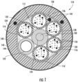
- a cable in the form of a fiber optic cable 110 may be an outside-plant loose tube cable, an indoor cable with fire-resistant/retardant properties, an indoor/outdoor cable, or another type of cable, such as a datacenter interconnect cable with micro-modules or a hybrid fiber optic cable including conductive elements.
- the cable 110 includes a core 112 (e.g., sub-assembly, micro-module), which may be located in the center of the cable 110 or elsewhere and may be the only core of the cable 110 or one of several cores.
- the core 112 of the cable 110 includes core elements 114.
- the core elements 114 include a tube 116, such as a buffer tube surrounding at least one optical fiber 118, a tight-buffer surrounding an optical fiber, or other tube.
- the tube 116 may contain two, four, six, twelve, twenty-four or other numbers of optical fibers 118.
- the core elements 114 additionally or alternatively include a tube 116 in the form of a dielectric insulator surrounding a conductive wire or wires, such as for a hybrid cable.
- the tube 116 further includes a water-blocking element, such as gel (e.g., grease, petroleum-based gel) or an absorbent polymer (e.g., super-absorbent polymer particles or powder).
- a water-blocking element such as gel (e.g., grease, petroleum-based gel) or an absorbent polymer (e.g., super-absorbent polymer particles or powder).
- the tube 116 includes yarn 120 carrying (e.g., impregnated with) super-absorbent polymer, such as at least one water-blocking yarn 120, at least two such yarns, or at least four such yarns per tube 116.
- the tube 116 includes super-absorbent polymer without a separate carrier, such as where the super-absorbent polymer is loose or attached to interior walls of the tube.
- particles of super-absorbent polymer are partially embedded in walls of the tube 116 (interior and/or exterior walls of the tube) or bonded thereto with an adhesive.
- the particles of super-absorbent polymer may be pneumatically sprayed onto the tube 116 walls during extrusion of the tube 116 and embedded in the tube 116 while the tube 116 is tacky, such as from extrusion processes.
- the optical fiber 118 of the tube 116 is a glass optical fiber, having a fiber optic core surrounded by a cladding (shown as a circle surrounding a dot in FIG. 1 ). Some such glass optical fibers may also include one or more polymeric coatings.
- the optical fiber 118 of the tube 116 is a single mode optical fiber in some embodiments, a multi-mode optical fiber in other embodiments, a multi-core optical fiber in still other embodiments.
- the optical fiber 118 may be bend resistant (e.g., bend insensitive optical fiber, such as CLEARCURVE TM optical fiber manufactured by Corning Incorporated of Corning, New York) and/or may have various dimensional characteristics, such as fibers with 200 ⁇ m coating outer diameters, for example.
- the optical fiber 118 may be color-coated and/or tight-buffered.
- the optical fiber 118 may be one of several optical fibers aligned and bound together in a fiber ribbon form.
- the core 112 of the cable 110 includes a plurality of additional core elements (e.g., elongate elements extending lengthwise through the cable 110), in addition to the tube 116, such as at least three additional core elements, at least five additional core elements.
- the plurality of additional core elements includes at least one of a filler rod 122 and/or an additional tube 116'.
- the core elements 114 may also or alternatively include straight or stranded conductive wires (e.g., copper or aluminum wires) or other elements.
- the core elements are all about the same size and cross-sectional shape (see FIG. 1 ), such as all being round and having diameters of within 10% of the diameter of the largest of the core elements 114.
- core elements 114 may vary in size and/or shape.
- the cable 110 may include a film (e.g., membrane, sleeve), shown as a single-layered film 126 in FIG. 1 or a binder 127 (e.g., binder yarns, etc.) in FIG. 2 , exterior to some or all of the core elements 114.
- a film e.g., membrane, sleeve
- binder 127 e.g., binder yarns, etc.
- the film may serve as a binder, where the tube 116 and the plurality of additional core elements 116', 122 are at least partially constrained (i.e., held in place) and directly or indirectly bound to one another by the film 126 or binder 127.
- the film 126 or binder 127 may directly contact the core elements 114 to hold the core elements 114 against a central strength member 124 and/or one another.
- the single-layered film 126 or binder 127 may be formed from a base or substrate polymer, such as polyethylene, polypropylene, etc., and flame-retardant filler material mixed therein (e.g., fire-retardant, fire-resistant, fireproof, flame-resistant, etc. material).
- a base or substrate polymer such as polyethylene, polypropylene, etc.
- flame-retardant filler material mixed therein (e.g., fire-retardant, fire-resistant, fireproof, flame-resistant, etc. material).
- filler material include as aluminum hydroxide (ATH), magnesium hydroxide (MDH), huntite and hydromagnesite, hydrates, red phosphorus, boron compounds such as borates, organohalogen compounds, and organophosphorus compounds.
- the manufacturing process further includes application of a jacket 134 to surround the core 112, thereby improving robustness and/or weather-ability of the cable 110 (see generally FIG. 1 ).
- the cable 110 may further include the central strength member 124, which may be a dielectric strength member, such as an up-jacketed glass-reinforced composite rod.
- the central strength member 124 may be or include a steel rod, stranded steel, tensile yarn or fibers (e.g., bundled aramid), or other strengthening materials.
- the central strength member 124 may include a center rod 128 and is up-jacketed with a polymeric material 130 (e.g., polyethylene with flame-retardant additive, polyvinyl chloride with flame-retardant additive, low-smoke zero-halogen polymer).
- powder particles 132 such as (1) super-absorbent polymer and/or another powder (e.g., talc) or another water-absorbing component (e.g., water-blocking tape, water-blocking yarns), (2) particles of flame-retardant material, such as those flame-retardant materials disclosed herein, (3) solid lubricant powders, such as talcum powder, graphite, etc., and/or (4) particles of intumescent material, such as materials containing at least 10% hydrates by weight, at least 30% hydrates by weight, at least 50% hydrates by weight, sodium silicates, and/or graphite, may be attached to the outer surface of the central strength member 124.
- another powder e.g., talc
- another water-absorbing component e.g., water-blocking tape, water-blocking yarns
- flame-retardant material such as those flame-retardant materials disclosed herein
- solid lubricant powders such as talcum powder, graphite
- Combinations of such powder particles may be used together, such as intumescent and flame-retardant powder. Further, some such powder particles may serve multiple, synergistic purposes, such as graphite serving to form a hard char layer upon exposure to fire and also serving to control coupling (e.g., lower friction) between adjoining surfaces.
- the intumescent particles may be formed from one or more intumescent materials that expands and forms char upon exposure to heat.
- the expansion of the intumescent material provides fire resistance by blocking air flow through cable jacket, such as through interstices formed between components in the core.
- intumescent particles are configured to expand in volume more than 500 times their unexpanded volume in the presence of fire, and in other embodiments are configured to expand in volume more than 1000 times their unexpanded volume in the presence of fire.
- the char formation provides a layer material with low heat transfer characteristics.
- intumescent particles may include intumescent materials that form light char and/or include intumescent materials that form hard char.
- the intumescent material of particles include one or more of the Exolit materials commercially available from Clariant, such as Exolit AP 765 (TP) material, intumescent powders manufactured by CeaseFire, intumescent powders manufactured by Zhejiang Longyou Sihai Chemical Industry Co., Ltd., Qingdao Sungraf Chemical Industry Co., Ltd., Dalian CR Science Development Co., Ltd., Weifang Menjie Chemicals Co., Ltd., or other manufacturers.
- TP Exolit AP 765
- At least some of the powder particles 132 may be partially embedded in the up-jacket 130, and attached thereto by pneumatically spraying the particles 132 against the up-jacket 130 while the up-jacket 130 is in a tacky and/or softened state.
- the powder particles 132 may increase or otherwise affect coupling between the central strength member 124 and the core elements 114 around the central strength member 124.
- the powder particles 132, 136 include super-absorbent polymer particles (e.g., sodium polyacrylate, ethylene maleic anhydride copolymer, polyacrylamide copolymer, polyvinyl alcohol copolymers, cross-linked polyethylene oxide, cross-linked carboxymethylcellulose, and starch-grafted copolymer of polyacrylonitrile) and the amount of super-absorbent polymer particles is less than 100 grams per square meter of surface area (g/m 2 ) of the respective component to which the powder particles are coupled (central strength member 124 or film 126).
- super-absorbent polymer particles e.g., sodium polyacrylate, ethylene maleic anhydride copolymer, polyacrylamide copolymer, polyvinyl alcohol copolymers, cross-linked polyethylene oxide, cross-linked carboxymethylcellulose, and starch-grafted copolymer of polyacrylonitrile
- the amount of super-absorbent polymer particles is less than 100 grams per square meter of surface area
- the amount of super-absorbent polymer particles is between 20 and 60 g/m 2 , such as between 25 and 40 g/m 2 .
- the amount of super-absorbent polymer or other water-blocking elements used in the cable is at least sufficient to block a one-meter pressure head of tap water in a one-meter length of the cable 110, according to industry standard water penetration tests, which may correspond to the above quantities, depending upon other characteristics of the respective cable 110, such as interstitial spacing between core elements 114.
- the particles 132 may be attached to the up-jacket 130 with an adhesive.
- the central strength member 124 includes the rod 128 without an up-jacket, and the particles 132 may be attached to the rod 128.
- a strength member such as a glass-reinforced rod or up-jacketed steel rod, includes particles 132 attached to the outer surface thereof, as disclosed above, without the strength member being a central strength member.
- the core elements 114 are stranded (i.e., wound) about the central strength member 124.
- the core elements 114 may be stranded in a repeating reverse-oscillatory pattern, such as so-called S-Z stranding or other stranding patterns (e.g., helical).
- the core elements 114 may be non-stranded.
- the core elements 114 include micro-modules or tight-buffered optical fibers that are oriented generally in parallel with one another inside the core 112.
- harness cables and/or interconnect cables may include a plurality of micro-modules, each including optical fibers and tensile yarn (e.g., aramid), where the micro-modules are bound together by the film 126 or binder 127.
- the aramid may be between the film 126 or binder 127 and the jacket 134, and/or the aramid may be inside the film 126 or binder 127, such as surrounding the stranded subunits (e.g., buffer tubes, tight-buffered fibers, micro-modules).
- Some such cables may not include a central strength member.
- Some embodiments include multiple cores or sub-assemblies, each bound by a film 126 or binder 127, and jacketed together in the same carrier/distribution cable.
- the multiple cores or sub-assemblies may be bound together with yet another film.
- techniques disclosed herein for rapid cooling/solidification during extrusion and inducing radial tension in the film 126 for coupling to a central strength member 124 may be unnecessary for manufacturing.
- Features of the cable 110 can be mixed and matched in different combinations to form other cables according to the disclosure herein.
- the film 126 of the cable 110 includes powder particles 136, which may be used for providing water blocking, retarding fire, choking off interstices (i.e., reducing the so called “chimney effect"), and/or for controlling coupling (e.g., decoupling) of adjoining surfaces in the cable 110.
- the powder particles 132, 136 may have an average maximum cross-sectional dimension of 500 micrometers ( ⁇ m) or less, such as 250 ⁇ m or less, 100 ⁇ m or less.
- the particles 132, 136 may be embedded in the film 126 or between the film 126 and the core elements 114 or in any of the intersticial spaces in the core, for example. In addition to blocking water, retarding fire, blocking interstices, etc., such placement may mitigate adhesion between certain core elements 114 during manufacturing of the cable 110.
- embedded material discontinuities in the jacket may provide tear paths to facilitate opening the jacket 134.
- ripcords 142 FIG. 1
- the powder particles 136 may further facilitate stripping the jacket 134 from the core 112 by decoupling surfaces adjacent to the powder particles 136. As such, depending upon placement of the powder particles 136, the particles 136 may facilitate decoupling of the jacket 134 from the film 126 or binders 127, such as for the cable 110 shown in FIG.
- jacket 134 and film 126 are adjoining (i.e., particles 136 placed between the jacket 134 and film 126), and/or may facilitate decoupling of the film 126 or binder 127 from the core elements 114 (i.e., particles 136 placed between the film 126 and core elements 114).
- jacket 134 may be a multilayer jacket consisting of one or more highly filled LSZH or FR inner layer(s) 140 and an unfilled or lightly filled outer layer 142, such as polyethylene (PE).
- PE polyethylene
- a bedding compound which consists of a very highly filled polymer blend for maximum fire retardancy, may be the inner layer 140 of the multilayer jacket. Due to the required burn performance of the cable 110, the outer layer 142 is developed as a thinner layer in order to minimize the impact of the outer layer 142 on the fire test results. However, due to strain concentrations in the matrix material of the highly filled inner layer 140, the outer layer 142 must be sufficiently thick to prevent cracking in the outer layer from typical handling and installation loads placed on the cable 110.
- the thickness of the outer layer 142 may be 100 ⁇ m or less, which is sufficient to preclude cracking of the outer layer 142 while providing low surface friction for blowing performance.
- a sufficiently thin outer skin layer 142 (as thin as 100 ⁇ m or less) made with unfilled or lightly filled PE, or other such suitable material, has minimal effect on overall burn performance of the cable while providing low friction for enhanced blowing performance during installation and high ultimate elongation for crack resistance.
- a coextrusion method may be used to manufacture the multiple layer jacket 134 in which the outer layer 142 may be a thinner layer. It is known that FR and LSZH materials provide superior fire properties; however, these materials do not necessarily provide low friction for blowing during installation or sufficient ultimate elongation to prevent cracking from handling and installation loads. The proposed outer layer 142, being made to have a low coefficient of friction improves the blowing performance and crack resistance of the cable. Coextrusion of the inner layer 140 and the outer layer 142 provides for very good adhesion between the jacket layers so that the layers will not separate during installation. Coextrusion also enables production of the jacket 134 in one step rather than a more expensive option of producing the cable using two separate steps.
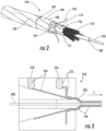
- an extruder 210 (e.g., crosshead) includes a flow path 212 for a first extrudable polymer 214 of the outer layer 242 and a flow path 216 for a second extrudable polymer 218 making up the inner layer 240. Similar extruders may have additional such flow paths for third, fourth, fifth, etc., extrudable polymers.
- an extruder 210 e.g., crosshead
- Similar extruders may have additional such flow paths for third, fourth, fifth, etc., extrudable polymers.
- the first and second extrudable polymers 214, 218 may be co-extrudable with one another, meaning that the first and second extrudable polymers 214, 218 have a sufficiently close melting point (e.g., within 80° C, within 50° C) and corresponding viscosity, among other parameters, that the first and second extrudable polymers 214, 218 are compatible for coextrusion.
- the extrusion paths 212, 216 converge such that the first and second extrudable polymers 214, 218 are co-extruded in the extruder 210.
- the first and second extrudable polymers 214, 216 may be discretely extruded, such as in tandem by separate extruders on a manufacturing line or by multiple passes through the same extruder.
- the first and second extrudable polymers 214, 218 are extruded around the core elements 220 of the cable that pass through the extruder 210 and into the extrusion cone 222 of the first and second extrudable polymers 214, 218.
- the core elements 220 may include optical fibers and/or a tube or tubes surrounding optical fibers, among other elements.
- the multilayer jacket 134 may then be rapidly cooled, such as in a water trough.
- Strain concentrations as great as 28 exist in a matrix material adjacent to filler particles for the filler particle loading shown in FIGS. 4 and 5 .
- Use of an unfilled or lightly filled, high ultimate elongation material for outer layer 142 significantly reduces the strain concentrations in the outer layer 142, thereby making the cable 110 with a dual layer jacket 134 less sensitive to surface cracking.
- Complete decoupling (separation) of the inner layer 140 and the outer layer142 fully decouples the strain concentrations in the inner layer 140 from the outer layer 142 which provides additional resistance to surface cracking in the outer layer 142.
- bonding between the inner layer 140 and the outer layer 142 reduces wrinkling of the thin outer layer 142 during installation.
- An optimal thickness of the outer layer 142 and the bond between the outer layer 142 and the inner layer 140 is necessary to provide sufficient surface crack resistance while maintaining wrinkling resistance.
- the cable 110 shown in FIGS. 1-2 has excellent adhesion at an interface 144 between the inner layer 140 and the outer layer 142, as demonstrated by the abrasion resistance of optical fiber cable sheaths test, Method E2A, acc. IEC 60794-1-2.
- Adhesion allows two layers to act as one jacket while each layer provides complementary properties.
- Inner layer 140 must be fire resistant with a nominal thickness of 1.05mm.
- the outer layer 142 which may also be defined as a skin layer, for example, having a nominal thickness of 100 ⁇ m or less, must be strong enough to withstand the blowing installation process while having a coefficient of friction that is as low as possible to enhance the same blowing process.
- the cable jacket 134 may have an inner layer 140 that includes a flame retardant non-corrosive (FRNC) material and an outer layer 142 that uses a non-FRNC material.
- FRNC flame retardant non-corrosive
- a high density material may be used for the outer layer 142 so that the mechanical properties of the material are superior to other conventional FRNC and non-FRNC materials.
- Coextrusion of the dual layer jacket134 provides strong adhesion between the layers 140 and 142. Moreover, the thinness of the outer layer 142 and the choice of a natural material for the outer layer 142 may make the outer layer 142 virtually invisible to field personnel while providing increased blowing performance.
- By having an outer layer 142 with a nominal thickness of 100 ⁇ m or less even if comprised of a non-FRNC material, the impact of the outer layer 142 on the fire performance of the cable 110 may be reduced. For example, based on the single cable burn test acc. IEC 60332-1-2, it was observed that using very thin non-FRNC material as the outer layer 142 has a neglible impact on the fire performance test results.
- Exemplary materials for use in the inner layer 140 include low smoke and fume FR non-halogen sheathing compounds, such as ECCOH TM 5549/1. These materials provide the cablesin accordance with aspects of the present disclosure a very high fire test performance, and combining excellent flame retardant properties due to high char forming with good processing and enhanced mechanical and thermal characteristics.
- MEGOLON ® S540 is a thermoplastic, halogen free cable sheathing compound which exhibits an excellent level of fire retardancy. This product is specifically aimed at designs of cables requiring a good degree of flexibility and the ability to meet the more stringent fire test specifications.
- LDD UV is a thermoplastic, halogen free, fire retardant, low smoke and fume cable compound, designed to meet premium requirements on fire retardancy enabling cables in accordance with aspects of the present disclosure to meet the more stringent fire specifications as well as maintain a high degree of flexibility.
- the product contains a chemical UV protection agent as well as our Low Died Droll (LDD) package for faster extrusion and low died droll.
- LDD Low Died Droll
- Exemplary materials for use in the outer layer 142 include a natural, UV-stabilized, colorable, bimodal high density (HD) jacketing compound, such as HE6068, which is produced with a bimodal process technology.
- the technology in this type of material allows the manufacturing of polymers outside the traditional MFR and density range making it possible to optimize processability, reduce shrinkage while providing durability and environmental stress crack resistance (ESCR).
- HE6068 contains a well dispersed UV-stabilizer in sufficient amount to provide a measure of weathering resistance.
- HE6068 offers substantially reduced shrinkage of the outer layer 142 which helps to maintain low signal attenuation for optical fiber communication cables and low jacket retraction while providing the mechanical and barrier properties desired.
- cables include multiple layers or levels of core elements stranded around a central strength member 124, where each layer includes a film 126 constraining the respective layer and where film 126 of the outer layer(s) indirectly surrounds the film 126 of the inner layer(s).
- the film 126 is not extruded, but is formed from laser-welded tape and/or a heat shrink material, for example.
- Some elements shown as integrally formed may be constructed of multiple parts or elements, the position of elements may be reversed or otherwise varied, and the nature or number of discrete elements or positions may be altered or varied.
- the film 126 with water-blocking powder may function as an extruded water-blocking element, thereby allowing for continuous cable manufacturing without replacing reels of the water-blocking tape; which, for example, may block water between armor (or other outer layers in a cable) and a core 112, such as a core of stacked fiber optic ribbons or a mono-tube core, or between other components in a cable.
- a core 112 such as a core of stacked fiber optic ribbons or a mono-tube core, or between other components in a cable.
- the order or sequence of any process, logical algorithm, or method steps may be varied or re-sequenced according to alternative embodiments.
Description
- This application claims the benefit of priority under 35 U.S.C. § 119 to
U.S. Provisional Application No. 62/260,843, filed on November 30, 2015 - Aspects of the present disclosure relate generally to cables, such as fiber optic cables, that may support and carry optical fibers as well as other cable components.
- Fiber optic cable, especially those in jurisdictions and applications with strict fire and smoke regulations, are designed to minimize the spread of fire, smoke, poisonous gases, and other hazards related to fire. Often thick jackets of flame-retardant (FR) and Low Smoke Zero Halogen (LSZH) materials are used to meet the demand for these types of fiber optic cables. However, these types of cables are often intended for installation into ducts that depends on an installation method whereby the cable is blown or jetted into the duct. Therefore, a cable jacket is needed that provides the benefits of FR and LSZH materials to pass international burn tests, such as IEC 60332-1-2 (single cable burn test), IEC 61034 (smoke density), and IEC 60332-3-24 (bunch cable burn test), and also have the strength and durability to withstand the stresses of installation, such as compression forces, impact and bending stresses, while providing a low coefficient of friction in order to provide the necessary blowing performance during installation.
- LSZH materials utilize a high percentage of filler particles, such as magnesium hydroxide, aluminum hydroxide and other suitable materials, which result in a very low ultimate elongation of the material, especially at elevated temperatures. This low ultimate elongation of LSZH materials can lead to jacket cracking when cable products are subjected to typical handling and installation loads.
-
WO 2015/142604 relates to a fiber optic cable with a core and a jacket surrounding the core. The jacket includes a base layer, a surface layer defining an exterior surface of the fiber optic cable, and an interface between the surface and base layers. The base layer is formed from a first composition that includes polyethylene. The surface layer has a thickness of at least 300 micrometers and is formed from a second composition that differs from the first composition. -
WO 2014/175229 relates to an optical fiber cable which comprises an optical fiber core wire and a cladding that covers the optical fiber core wire. The cladding is configured such that the surface thereof is provided with a plurality of projected parts which are formed of an inorganic material. - The invention relates to a fiber optical cable with the features of claim 1. The invention futher relates to a method of manufacturing an optical fiber cable with the features of claim 10. Aspects of composite jacket materials are disclosed that provide the necessary FR/LSZH and installation characteristics through the synergy of a multilayer composition. Fire retardancy is provided by using a FR, or in particular a LSZH material, while the strength, increased ultimate elongation and low coefficient of friction is provided by a less flame retardant or non-FR compound such as polyethylene (PE). Increased adhesion between these two different type of materials may be accomplished by coextruding a double layer jacket during production of the cable. Coextrusion provides excellent bond strength between the layers of different compounds, reducing or eliminating wrinkling and/or separation of the outer layer during the installation process.
- In accordance with aspects of the present disclosure, a fiber optic cable comprises a core subassembly comprising at least one optical fiber and a tube surrounding the optical fiber. A multi-layered jacket surrounds the core subassembly, wherein the jacket comprises an inner layer comprising a flame retardant (FR) material and an outer layer comprising a non flame retardant material having a lower coefficient of friction than the flame retardant material.
- In accordance with other aspects of the present disclosure, a multi-layered cable jacket comprises an inner layer comprising a flame retardant (FR) material and an outer layer comprising a non flame retardant material having a lower coefficient of friction than the flame retardant material.
- In accordance with yet other aspects of the present disclosure, a method of manufacturing an optical fiber cable includes providing a core subassembly and co-extruding a multi-layered jacket around the core subassembly, wherein the multi-layered jacket includes an inner layer comprising a flame retardant (FR) material and an outer layer comprising a non flame retardant material having a lower coefficient of friction than the flame retardant material.
- Additional features and advantages are set forth in the Detailed Description that follows, and in part will be readily apparent to those skilled in the art from the description or recognized by practicing the embodiments as described in the written description and claims hereof, as well as the appended drawings. It is to be understood that both the foregoing general description and the following Detailed Description are merely exemplary, and are intended to provide an overview or framework to understand the nature and character of the claims.
- The accompanying Figures are included to provide a further understanding, and are incorporated in and constitute a part of this specification. The drawings illustrate one or more embodiments, and together with the Detailed Description serve to explain principles and operations of the various embodiments. As such, the disclosure will become more fully understood from the following Detailed Description, taken in conjunction with the accompanying Figures, in which:
-
FIG. 1 is a cross-sectional view of a fiber optic cable in accordance with aspects of the present disclosure. -
FIG. 2 is a perspective view of a fiber optic cable in accordance with aspects of the present disclosure. -
FIG. 3 is a side cross-sectional view of a multi-layer extrusion structure in accordance with aspects of the present disclosure. -
FIG.4 is an illustration of a finite element model with 50% particle fill ratio based on volume, in accordance with aspects of the present disclosure. -
FIG. 5 is an illustration of a finite element contour strain plot showing strain concentration effects from fill particles with 0.05 strain applied in an x direction, in accordance with aspects of the present disclosure. - Before turning to the following Detailed Description and Figures, which illustrate exemplary embodiments in detail, it should be understood that the present inventive technology is not limited to the details or methodology set forth in the Detailed Description or illustrated in the Figures. For example, as will be understood by those of ordinary skill in the art, features and attributes associated with embodiments shown in one of the Figures or described in the text relating to one of the embodiments may well be applied to other embodiments shown in another of the Figures and/or described elsewhere in the text.
- Referring to
FIG. 1 , a cable in the form of a fiberoptic cable 110 may be an outside-plant loose tube cable, an indoor cable with fire-resistant/retardant properties, an indoor/outdoor cable, or another type of cable, such as a datacenter interconnect cable with micro-modules or a hybrid fiber optic cable including conductive elements. According to an exemplary embodiment, thecable 110 includes a core 112 (e.g., sub-assembly, micro-module), which may be located in the center of thecable 110 or elsewhere and may be the only core of thecable 110 or one of several cores. According to an exemplary embodiment, thecore 112 of thecable 110 includescore elements 114. - In some embodiments, the
core elements 114 include atube 116, such as a buffer tube surrounding at least oneoptical fiber 118, a tight-buffer surrounding an optical fiber, or other tube. According to an exemplary embodiment, thetube 116 may contain two, four, six, twelve, twenty-four or other numbers ofoptical fibers 118. In contemplated embodiments, thecore elements 114 additionally or alternatively include atube 116 in the form of a dielectric insulator surrounding a conductive wire or wires, such as for a hybrid cable. - In some embodiments, the
tube 116 further includes a water-blocking element, such as gel (e.g., grease, petroleum-based gel) or an absorbent polymer (e.g., super-absorbent polymer particles or powder). In some such embodiments, thetube 116 includesyarn 120 carrying (e.g., impregnated with) super-absorbent polymer, such as at least one water-blockingyarn 120, at least two such yarns, or at least four such yarns pertube 116. In other contemplated embodiments, thetube 116 includes super-absorbent polymer without a separate carrier, such as where the super-absorbent polymer is loose or attached to interior walls of the tube. In some such embodiments, particles of super-absorbent polymer are partially embedded in walls of the tube 116 (interior and/or exterior walls of the tube) or bonded thereto with an adhesive. For example, the particles of super-absorbent polymer may be pneumatically sprayed onto thetube 116 walls during extrusion of thetube 116 and embedded in thetube 116 while thetube 116 is tacky, such as from extrusion processes. - According to an exemplary embodiment, the
optical fiber 118 of thetube 116 is a glass optical fiber, having a fiber optic core surrounded by a cladding (shown as a circle surrounding a dot inFIG. 1 ). Some such glass optical fibers may also include one or more polymeric coatings. Theoptical fiber 118 of thetube 116 is a single mode optical fiber in some embodiments, a multi-mode optical fiber in other embodiments, a multi-core optical fiber in still other embodiments. Theoptical fiber 118 may be bend resistant (e.g., bend insensitive optical fiber, such as CLEARCURVE™ optical fiber manufactured by Corning Incorporated of Corning, New York) and/or may have various dimensional characteristics, such as fibers with 200 µm coating outer diameters, for example. Theoptical fiber 118 may be color-coated and/or tight-buffered. Theoptical fiber 118 may be one of several optical fibers aligned and bound together in a fiber ribbon form. - According to an exemplary embodiment, the
core 112 of thecable 110 includes a plurality of additional core elements (e.g., elongate elements extending lengthwise through the cable 110), in addition to thetube 116, such as at least three additional core elements, at least five additional core elements. According to an exemplary embodiment, the plurality of additional core elements includes at least one of afiller rod 122 and/or an additional tube 116'. In other contemplated embodiments, thecore elements 114 may also or alternatively include straight or stranded conductive wires (e.g., copper or aluminum wires) or other elements. In some embodiments, the core elements are all about the same size and cross-sectional shape (seeFIG. 1 ), such as all being round and having diameters of within 10% of the diameter of the largest of thecore elements 114. In other embodiments,core elements 114 may vary in size and/or shape. - Referring now to
FIGS. 1-2 , thecable 110 may include a film (e.g., membrane, sleeve), shown as a single-layered film 126 inFIG. 1 or a binder 127 (e.g., binder yarns, etc.) inFIG. 2 , exterior to some or all of thecore elements 114. - In some embodiments, the film may serve as a binder, where the
tube 116 and the plurality ofadditional core elements 116', 122 are at least partially constrained (i.e., held in place) and directly or indirectly bound to one another by thefilm 126 orbinder 127. In some embodiments, thefilm 126 orbinder 127 may directly contact thecore elements 114 to hold thecore elements 114 against acentral strength member 124 and/or one another. - In some embodiments, the single-layered
film 126 orbinder 127 may be formed from a base or substrate polymer, such as polyethylene, polypropylene, etc., and flame-retardant filler material mixed therein (e.g., fire-retardant, fire-resistant, fireproof, flame-resistant, etc. material). Examples of such filler material include as aluminum hydroxide (ATH), magnesium hydroxide (MDH), huntite and hydromagnesite, hydrates, red phosphorus, boron compounds such as borates, organohalogen compounds, and organophosphorus compounds. - Subsequent to the application of the
film 126 orbinder 127, for example, the manufacturing process further includes application of ajacket 134 to surround thecore 112, thereby improving robustness and/or weather-ability of the cable 110 (see generallyFIG. 1 ). - As shown in
FIGS. 1 and2 , thecable 110 may further include thecentral strength member 124, which may be a dielectric strength member, such as an up-jacketed glass-reinforced composite rod. In other embodiments, thecentral strength member 124 may be or include a steel rod, stranded steel, tensile yarn or fibers (e.g., bundled aramid), or other strengthening materials. As shown inFIGS. 1 and2 , thecentral strength member 124 may include acenter rod 128 and is up-jacketed with a polymeric material 130 (e.g., polyethylene with flame-retardant additive, polyvinyl chloride with flame-retardant additive, low-smoke zero-halogen polymer). - According to an exemplary embodiment,
powder particles 132, such as (1) super-absorbent polymer and/or another powder (e.g., talc) or another water-absorbing component (e.g., water-blocking tape, water-blocking yarns), (2) particles of flame-retardant material, such as those flame-retardant materials disclosed herein, (3) solid lubricant powders, such as talcum powder, graphite, etc., and/or (4) particles of intumescent material, such as materials containing at least 10% hydrates by weight, at least 30% hydrates by weight, at least 50% hydrates by weight, sodium silicates, and/or graphite, may be attached to the outer surface of thecentral strength member 124. Combinations of such powder particles may be used together, such as intumescent and flame-retardant powder. Further, some such powder particles may serve multiple, synergistic purposes, such as graphite serving to form a hard char layer upon exposure to fire and also serving to control coupling (e.g., lower friction) between adjoining surfaces. - According to an exemplary embodiment, the intumescent particles may be formed from one or more intumescent materials that expands and forms char upon exposure to heat. The expansion of the intumescent material provides fire resistance by blocking air flow through cable jacket, such as through interstices formed between components in the core. In various embodiments, intumescent particles are configured to expand in volume more than 500 times their unexpanded volume in the presence of fire, and in other embodiments are configured to expand in volume more than 1000 times their unexpanded volume in the presence of fire. In addition, the char formation provides a layer material with low heat transfer characteristics. In various embodiments, intumescent particles may include intumescent materials that form light char and/or include intumescent materials that form hard char. In various embodiments, the intumescent material of particles include one or more of the Exolit materials commercially available from Clariant, such as Exolit AP 765 (TP) material, intumescent powders manufactured by CeaseFire, intumescent powders manufactured by Zhejiang Longyou Sihai Chemical Industry Co., Ltd., Qingdao Sungraf Chemical Industry Co., Ltd., Dalian CR Science Development Co., Ltd., Weifang Menjie Chemicals Co., Ltd., or other manufacturers. At least some of the
powder particles 132 may be partially embedded in the up-jacket 130, and attached thereto by pneumatically spraying theparticles 132 against the up-jacket 130 while the up-jacket 130 is in a tacky and/or softened state. Thepowder particles 132 may increase or otherwise affect coupling between thecentral strength member 124 and thecore elements 114 around thecentral strength member 124. - According to an exemplary embodiment, the
powder particles central strength member 124 or film 126). In some such embodiments, the amount of super-absorbent polymer particles is between 20 and 60 g/m2, such as between 25 and 40 g/m2. According to an exemplary embodiment, the amount of super-absorbent polymer or other water-blocking elements used in the cable is at least sufficient to block a one-meter pressure head of tap water in a one-meter length of thecable 110, according to industry standard water penetration tests, which may correspond to the above quantities, depending upon other characteristics of therespective cable 110, such as interstitial spacing betweencore elements 114. - Alternatively or in addition thereto, the
particles 132 may be attached to the up-jacket 130 with an adhesive. In some embodiments, thecentral strength member 124 includes therod 128 without an up-jacket, and theparticles 132 may be attached to therod 128. In contemplated embodiments, a strength member, such as a glass-reinforced rod or up-jacketed steel rod, includesparticles 132 attached to the outer surface thereof, as disclosed above, without the strength member being a central strength member. - In some embodiments, the
core elements 114 are stranded (i.e., wound) about thecentral strength member 124. Thecore elements 114 may be stranded in a repeating reverse-oscillatory pattern, such as so-called S-Z stranding or other stranding patterns (e.g., helical). In other contemplated embodiments, thecore elements 114 may be non-stranded. In some such embodiments, thecore elements 114 include micro-modules or tight-buffered optical fibers that are oriented generally in parallel with one another inside thecore 112. For example, harness cables and/or interconnect cables may include a plurality of micro-modules, each including optical fibers and tensile yarn (e.g., aramid), where the micro-modules are bound together by thefilm 126 orbinder 127. The aramid may be between thefilm 126 orbinder 127 and thejacket 134, and/or the aramid may be inside thefilm 126 orbinder 127, such as surrounding the stranded subunits (e.g., buffer tubes, tight-buffered fibers, micro-modules). Some such cables may not include a central strength member. Some embodiments, include multiple cores or sub-assemblies, each bound by afilm 126 orbinder 127, and jacketed together in the same carrier/distribution cable. The multiple cores or sub-assemblies may be bound together with yet another film. For some such embodiments, techniques disclosed herein for rapid cooling/solidification during extrusion and inducing radial tension in thefilm 126 for coupling to acentral strength member 124 may be unnecessary for manufacturing. Features of thecable 110 can be mixed and matched in different combinations to form other cables according to the disclosure herein. - Referring again to
FIG. 1 , in some embodiments thefilm 126 of thecable 110 includespowder particles 136, which may be used for providing water blocking, retarding fire, choking off interstices (i.e., reducing the so called "chimney effect"), and/or for controlling coupling (e.g., decoupling) of adjoining surfaces in thecable 110. In some embodiments, thepowder particles particles film 126 or between thefilm 126 and thecore elements 114 or in any of the intersticial spaces in the core, for example. In addition to blocking water, retarding fire, blocking interstices, etc., such placement may mitigate adhesion between certaincore elements 114 during manufacturing of thecable 110. - According to an exemplary embodiment, embedded material discontinuities in the jacket (see generally features 142 of
FIG. 1 for placement of such features), such as narrow strips of co-extruded polypropylene embedded in apolyethylene jacket 134, may provide tear paths to facilitate opening thejacket 134. Alternatively, ripcords 142 (FIG. 1 ) in or adjoining thejacket 134 may facilitate opening thejacket 134. Thepowder particles 136 may further facilitate stripping thejacket 134 from thecore 112 by decoupling surfaces adjacent to thepowder particles 136. As such, depending upon placement of thepowder particles 136, theparticles 136 may facilitate decoupling of thejacket 134 from thefilm 126 orbinders 127, such as for thecable 110 shown inFIG. 1 where thejacket 134 andfilm 126 are adjoining (i.e.,particles 136 placed between thejacket 134 and film 126), and/or may facilitate decoupling of thefilm 126 orbinder 127 from the core elements 114 (i.e.,particles 136 placed between thefilm 126 and core elements 114). - As shown in
FIGS. 1 and2 ,jacket 134 may be a multilayer jacket consisting of one or more highly filled LSZH or FR inner layer(s) 140 and an unfilled or lightly filledouter layer 142, such as polyethylene (PE). A bedding compound, which consists of a very highly filled polymer blend for maximum fire retardancy, may be theinner layer 140 of the multilayer jacket. Due to the required burn performance of thecable 110, theouter layer 142 is developed as a thinner layer in order to minimize the impact of theouter layer 142 on the fire test results. However, due to strain concentrations in the matrix material of the highly filledinner layer 140, theouter layer 142 must be sufficiently thick to prevent cracking in the outer layer from typical handling and installation loads placed on thecable 110. In accordance with aspects of the present disclosure, the thickness of theouter layer 142 may be 100µm or less, which is sufficient to preclude cracking of theouter layer 142 while providing low surface friction for blowing performance. A sufficiently thin outer skin layer 142 (as thin as 100µm or less) made with unfilled or lightly filled PE, or other such suitable material, has minimal effect on overall burn performance of the cable while providing low friction for enhanced blowing performance during installation and high ultimate elongation for crack resistance. - A coextrusion method may be used to manufacture the
multiple layer jacket 134 in which theouter layer 142 may be a thinner layer. It is known that FR and LSZH materials provide superior fire properties; however, these materials do not necessarily provide low friction for blowing during installation or sufficient ultimate elongation to prevent cracking from handling and installation loads. The proposedouter layer 142, being made to have a low coefficient of friction improves the blowing performance and crack resistance of the cable. Coextrusion of theinner layer 140 and theouter layer 142 provides for very good adhesion between the jacket layers so that the layers will not separate during installation. Coextrusion also enables production of thejacket 134 in one step rather than a more expensive option of producing the cable using two separate steps. - Referring to
FIG. 3 , an extruder 210 (e.g., crosshead) includes aflow path 212 for afirst extrudable polymer 214 of the outer layer 242 and aflow path 216 for asecond extrudable polymer 218 making up the inner layer 240. Similar extruders may have additional such flow paths for third, fourth, fifth, etc., extrudable polymers. InFIG. 3 , the first andsecond extrudable polymers second extrudable polymers second extrudable polymers extrusion paths second extrudable polymers extruder 210. - In other embodiments, the first and
second extrudable polymers second extrudable polymers core elements 220 of the cable that pass through theextruder 210 and into theextrusion cone 222 of the first andsecond extrudable polymers core elements 220 may include optical fibers and/or a tube or tubes surrounding optical fibers, among other elements. In some embodiments, themultilayer jacket 134 may then be rapidly cooled, such as in a water trough. - Strain concentrations as great as 28 (1.399/0.05=28) exist in a matrix material adjacent to filler particles for the filler particle loading shown in
FIGS. 4 and 5 . Use of an unfilled or lightly filled, high ultimate elongation material forouter layer 142 significantly reduces the strain concentrations in theouter layer 142, thereby making thecable 110 with adual layer jacket 134 less sensitive to surface cracking. Complete decoupling (separation) of theinner layer 140 and the outer layer142 fully decouples the strain concentrations in theinner layer 140 from theouter layer 142 which provides additional resistance to surface cracking in theouter layer 142. In addition, bonding between theinner layer 140 and theouter layer 142 reduces wrinkling of the thinouter layer 142 during installation. An optimal thickness of theouter layer 142 and the bond between theouter layer 142 and theinner layer 140 is necessary to provide sufficient surface crack resistance while maintaining wrinkling resistance. - In accordance with aspects of the present disclosure, the
cable 110 shown inFIGS. 1-2 , has excellent adhesion at aninterface 144 between theinner layer 140 and theouter layer 142, as demonstrated by the abrasion resistance of optical fiber cable sheaths test, Method E2A, acc. IEC 60794-1-2. Adhesion allows two layers to act as one jacket while each layer provides complementary properties.Inner layer 140 must be fire resistant with a nominal thickness of 1.05mm. Theouter layer 142, which may also be defined as a skin layer, for example, having a nominal thickness of 100µm or less, must be strong enough to withstand the blowing installation process while having a coefficient of friction that is as low as possible to enhance the same blowing process. - In accordance with aspects of the present disclosure, the
cable jacket 134 may have aninner layer 140 that includes a flame retardant non-corrosive (FRNC) material and anouter layer 142 that uses a non-FRNC material. A high density material may be used for theouter layer 142 so that the mechanical properties of the material are superior to other conventional FRNC and non-FRNC materials. - Coextrusion of the dual layer jacket134 provides strong adhesion between the
layers outer layer 142 and the choice of a natural material for theouter layer 142 may make theouter layer 142 virtually invisible to field personnel while providing increased blowing performance. By having anouter layer 142 with a nominal thickness of 100µm or less, even if comprised of a non-FRNC material, the impact of theouter layer 142 on the fire performance of thecable 110 may be reduced. For example, based on the single cable burn test acc. IEC 60332-1-2, it was observed that using very thin non-FRNC material as theouter layer 142 has a neglible impact on the fire performance test results. - Exemplary materials for use in the
inner layer 140 include low smoke and fume FR non-halogen sheathing compounds, such as ECCOH™ 5549/1. These materials provide the cablesin accordance with aspects of the present disclosure a very high fire test performance, and combining excellent flame retardant properties due to high char forming with good processing and enhanced mechanical and thermal characteristics. MEGOLON® S540 is a thermoplastic, halogen free cable sheathing compound which exhibits an excellent level of fire retardancy. This product is specifically aimed at designs of cables requiring a good degree of flexibility and the ability to meet the more stringent fire test specifications. CONGuard S 6650 S LDD UV is a thermoplastic, halogen free, fire retardant, low smoke and fume cable compound, designed to meet premium requirements on fire retardancy enabling cables in accordance with aspects of the present disclosure to meet the more stringent fire specifications as well as maintain a high degree of flexibility. The product contains a chemical UV protection agent as well as our Low Died Droll (LDD) package for faster extrusion and low died droll. - Exemplary materials for use in the
outer layer 142 include a natural, UV-stabilized, colorable, bimodal high density (HD) jacketing compound, such as HE6068, which is produced with a bimodal process technology. The technology in this type of material allows the manufacturing of polymers outside the traditional MFR and density range making it possible to optimize processability, reduce shrinkage while providing durability and environmental stress crack resistance (ESCR). HE6068 contains a well dispersed UV-stabilizer in sufficient amount to provide a measure of weathering resistance. HE6068 offers substantially reduced shrinkage of theouter layer 142 which helps to maintain low signal attenuation for optical fiber communication cables and low jacket retraction while providing the mechanical and barrier properties desired. - The construction and arrangements of the cables, as shown in the various exemplary embodiments, are illustrative only. Although only a few embodiments have been described in detail in this disclosure, many modifications are possible (e.g., variations in sizes, dimensions, structures, shapes, and proportions of the various elements, values of parameters, mounting arrangements, use of materials, colors, orientations) without materially departing from the novel teachings and advantages of the subject matter described herein. For example, in some embodiments, cables include multiple layers or levels of core elements stranded around a
central strength member 124, where each layer includes afilm 126 constraining the respective layer and wherefilm 126 of the outer layer(s) indirectly surrounds thefilm 126 of the inner layer(s). In contemplated embodiments, thefilm 126 is not extruded, but is formed from laser-welded tape and/or a heat shrink material, for example. Some elements shown as integrally formed may be constructed of multiple parts or elements, the position of elements may be reversed or otherwise varied, and the nature or number of discrete elements or positions may be altered or varied. In some contemplated embodiments, thefilm 126 with water-blocking powder, as disclosed herein, may function as an extruded water-blocking element, thereby allowing for continuous cable manufacturing without replacing reels of the water-blocking tape; which, for example, may block water between armor (or other outer layers in a cable) and acore 112, such as a core of stacked fiber optic ribbons or a mono-tube core, or between other components in a cable. The order or sequence of any process, logical algorithm, or method steps may be varied or re-sequenced according to alternative embodiments.
Claims (12)
- A fiber optic cable, comprising:(A) a core subassembly (112) comprising at least the following core elements (114):(i) at least one optical fiber (118); and(ii) a tube (116) surrounding the optical fiber (118); and(B) a jacket (134) surrounding the core subassembly (112), wherein the jacket (134) comprises:(i) an inner layer (140) comprising a flame retardant (FR) material; and(ii) an outer layer (142) comprising a non flame retardant material having a lower coefficient of friction than the flame retardant material, characterized in that an average thickness of the outer layer (142) is equal to or less than 100 microns.
- The fiber optic cable of claim 1, wherein the core subassembly (112) further comprises (iii) one or more additional core elements (114) comprising at least one additional tube (116) surrounding another optical fiber (118), the fiber optic cable (110) further comprising a central strength member (124), wherein the core elements (114) are stranded around the central strength member (124) in a pattern of stranding including reversals in lay direction of the core elements (114).
- The fiber optic cable of claim 1 or 2, wherein the flame retardant material of the inner layer (140) is a low smoke zero halogen (LSZH) material comprising a filler material.
- The fiber optic cable of claim 3, wherein the filler material comprises magnesium hydroxide or aluminum hydroxide.
- The fiber optic cable of any of claims 1 to 4, wherein the multi-layered jacket (134) is a co-extruded multilayer jacket (134), the inner layer (140) and the thin outer layer (142) having sufficient bond strength to prevent wrinkling of the outer layer (142) during installation.
- The fiber optic cable of any of claims 1 to 5, wherein the non flame retardant material of the thin outer layer (142) comprises a polyethelene material.
- The fiber optic cable of any of claims 1 to 6, further comprising a thin film structure surrounding the core subassembly (112).
- The fiber optic cable of claim 7, wherein the thin film structure is a multi-layered flame-retardant film structure.
- The fiber optic cable of claim 7, wherein the thin film structure directly contacts the jacket (134).
- A method of manufacturing an optical fiber cable comprising:providing a core subassembly (112); and
co-extruding a multi-layered jacket (134) around the core subassembly (112), wherein the multi-layered jacket (134) includes an inner layer (140) comprising a flame retardant (FR) material andan outer layer (142) comprising a non flame retardant material having a lower coefficient of friction than the flame retardant material, characterized in that a thickness of the thin outer layer (142) is equal to or less than 100 microns. - The method claim 10, wherein the core subassembly (112) comprises at least one optical fiber (118) and a tube (116) surrounding the optical fiber (118).
- The method of claim 10 or 11, wherein the step of co-extruding the inner layer (140) and the outer layer (142) forms a bond of sufficient strength between the inner layer (140) and the outer layer (142) to prevent wrinkling of the outer layer (142) during installation.
Applications Claiming Priority (2)
| Application Number | Priority Date | Filing Date | Title |
|---|---|---|---|
| US201562260843P | 2015-11-30 | 2015-11-30 | |
| PCT/US2016/057611 WO2017095542A1 (en) | 2015-11-30 | 2016-10-19 | Coextruded jacket for flame retardant fiber optic cables |
Publications (2)
| Publication Number | Publication Date |
|---|---|
| EP3384335A1 EP3384335A1 (en) | 2018-10-10 |
| EP3384335B1 true EP3384335B1 (en) | 2023-02-22 |
Family
ID=57227124
Family Applications (1)
| Application Number | Title | Priority Date | Filing Date |
|---|---|---|---|
| EP16790814.4A Active EP3384335B1 (en) | 2015-11-30 | 2016-10-19 | Coextruded jacket for flame retardant fiber optic cables |
Country Status (8)
| Country | Link |
|---|---|
| US (1) | US9784935B2 (en) |
| EP (1) | EP3384335B1 (en) |
| CN (1) | CN108431658A (en) |
| AU (1) | AU2016362901A1 (en) |
| CA (1) | CA3006752A1 (en) |
| ES (1) | ES2945057T3 (en) |
| PL (1) | PL3384335T3 (en) |
| WO (1) | WO2017095542A1 (en) |
Families Citing this family (16)
| Publication number | Priority date | Publication date | Assignee | Title |
|---|---|---|---|---|
| PL3088929T3 (en) * | 2015-04-27 | 2020-10-19 | Corning Optical Communications LLC | Optical fiber cable |
| EP3270201B1 (en) | 2016-07-11 | 2020-08-19 | Corning Optical Communications LLC | Fiber optic cable |
| US10527808B2 (en) * | 2017-05-30 | 2020-01-07 | Sterlite Technologies Limited | Flame retardant optical fiber cable |
| US11287590B2 (en) | 2017-06-12 | 2022-03-29 | Corning Research & Development Corporation | In-road interface protected cable |
| ES2928651T3 (en) * | 2017-10-06 | 2022-11-21 | Prysmian Spa | High Fiber Count Fire Resistant Fiber Optic Cable |
| DE102017129020A1 (en) * | 2017-12-06 | 2019-06-06 | Südkabel GmbH | Cable with fire protection layer |
| EP3540487A1 (en) * | 2018-03-12 | 2019-09-18 | Corning Research & Development Corporation | Optical fiber cable with improved fire protection performance |
| WO2020081411A1 (en) | 2018-10-16 | 2020-04-23 | Corning Research & Development Corporation | Multilayer low attenuation drop cable |
| US11778700B2 (en) | 2018-12-07 | 2023-10-03 | Nvent Services Gmbh | Flammability of heating cable |
| US11322275B2 (en) | 2019-01-18 | 2022-05-03 | Comtran Cable Llc | Flame resistant data cables and related methods |
| US11846370B2 (en) | 2019-03-26 | 2023-12-19 | Titeflex Corporation | Multilayer composite pipe and pipe assemblies including reflective insulation |
| EP3764144B1 (en) | 2019-07-09 | 2023-02-22 | Corning Research & Development Corporation | Flame retardant fiber optic cable with halogen free sheath for blowing applications |
| WO2021080798A1 (en) * | 2019-10-21 | 2021-04-29 | Ofs Fitel, Llc | Outdoor/indoor optical cables with low-friction skin layer |
| EP4248252A1 (en) * | 2020-11-20 | 2023-09-27 | Corning Research & Development Corporation | Optical cable reinforcement with low acidity |
| CN113270229A (en) * | 2021-05-25 | 2021-08-17 | 国网河南省电力公司西峡县供电公司 | Photoelectric composite cable with high stable transmission performance |
| WO2023086290A1 (en) * | 2021-11-09 | 2023-05-19 | Corning Research & Development Corporation | Optical fiber cable having one or more cable components with layer-by-layer flame retardant coating |
Family Cites Families (23)
| Publication number | Priority date | Publication date | Assignee | Title |
|---|---|---|---|---|
| NO153511C (en) * | 1983-08-25 | 1986-04-02 | Standard Tel Kabelfab As | FIRE AND OIL RESISTANT CABLE. |
| GB8815977D0 (en) * | 1988-07-05 | 1988-08-10 | British Telecomm | Transmission line ducts |
| US5173960A (en) * | 1992-03-06 | 1992-12-22 | At&T Bell Laboratories | Cable having superior resistance to flame spread and smoke evolution |
| JP2000066072A (en) * | 1998-08-21 | 2000-03-03 | Furukawa Electric Co Ltd:The | Reinforcing cord |
| US6249628B1 (en) * | 1999-06-10 | 2001-06-19 | Siecor Operations, Llc | Fiber optic cable units |
| US7218821B2 (en) * | 2004-08-20 | 2007-05-15 | Furukawa Electric North America Inc. | Optical fiber cables |
| CN200986605Y (en) | 2006-12-14 | 2007-12-05 | 北京康宁光缆有限公司 | Fire resistant optical cable |
| US20090087148A1 (en) * | 2007-09-28 | 2009-04-02 | Bradley Kelvin B | Optical fiber cables |
| CA2989478C (en) * | 2008-08-15 | 2019-02-26 | Corning Optical Communications LLC | Optical fiber assemblies, and methods and apparatus for the manufacture thereof |
| US8912253B2 (en) * | 2009-04-02 | 2014-12-16 | Conductores Monterrey, S.A. De C.V. | Easy-to-install electrical cable |
| CZ2009707A3 (en) * | 2009-10-27 | 2011-05-04 | Kabelovna Kabex A.S. | Fire-inhibiting protective wiring tube for cables |
| GB2480452B (en) * | 2010-05-18 | 2014-10-08 | Tyco Electronics Ltd Uk | High temperature insulated wire or cable |
| US8639076B2 (en) * | 2010-08-17 | 2014-01-28 | Nexans | Fiber optic cable with improved low temperature and compression resistance |
| EP2740000B8 (en) * | 2011-08-04 | 2020-03-25 | Prysmian Telecom Cables and Systems UK Limited | Low-fire hazard optical fiber drop cable |
| CN104583828B (en) * | 2012-08-08 | 2018-06-01 | 普睿司曼股份公司 | For the fire-retardant cable of air-sweeping type installation |
| US8620124B1 (en) * | 2012-09-26 | 2013-12-31 | Corning Cable Systems Llc | Binder film for a fiber optic cable |
| JP6331260B2 (en) * | 2013-04-25 | 2018-05-30 | 住友電気工業株式会社 | Fiber optic cable |
| US9459423B2 (en) * | 2013-11-12 | 2016-10-04 | Corning Cable Systems Llc | Fire resistant optical communication cable using ceramic-forming fibers |
| US9547147B2 (en) * | 2013-12-20 | 2017-01-17 | Corning Optical Communications LLC | Fiber optic cable with extruded tape |
| CN203910317U (en) | 2013-12-30 | 2014-10-29 | 北京市交泰电缆有限公司 | Fire resistant power cable |
| CN203689958U (en) | 2013-12-30 | 2014-07-02 | 北京市交泰电缆有限公司 | Fire resistant sheath shielding flexible cable |
| CN203746560U (en) | 2014-02-21 | 2014-07-30 | 上海新启电缆科技有限公司 | Cross-linked polyethylene insulated fireproof flame-retardant power cable |
| CN106233180B (en) * | 2014-03-18 | 2019-10-15 | 康宁光电通信有限责任公司 | Sheath for Connectorized fiber optic cabling |
-
2016
- 2016-10-19 AU AU2016362901A patent/AU2016362901A1/en not_active Abandoned
- 2016-10-19 EP EP16790814.4A patent/EP3384335B1/en active Active
- 2016-10-19 PL PL16790814.4T patent/PL3384335T3/en unknown
- 2016-10-19 CA CA3006752A patent/CA3006752A1/en active Pending
- 2016-10-19 ES ES16790814T patent/ES2945057T3/en active Active
- 2016-10-19 CN CN201680077929.1A patent/CN108431658A/en active Pending
- 2016-10-19 WO PCT/US2016/057611 patent/WO2017095542A1/en active Application Filing
- 2016-11-01 US US15/339,993 patent/US9784935B2/en active Active
Also Published As
| Publication number | Publication date |
|---|---|
| US9784935B2 (en) | 2017-10-10 |
| CN108431658A (en) | 2018-08-21 |
| CA3006752A1 (en) | 2017-06-08 |
| WO2017095542A1 (en) | 2017-06-08 |
| PL3384335T3 (en) | 2023-06-12 |
| US20170153405A1 (en) | 2017-06-01 |
| ES2945057T3 (en) | 2023-06-28 |
| EP3384335A1 (en) | 2018-10-10 |
| AU2016362901A1 (en) | 2018-06-28 |
Similar Documents
| Publication | Publication Date | Title |
|---|---|---|
| EP3384335B1 (en) | Coextruded jacket for flame retardant fiber optic cables | |
| US10725257B2 (en) | Fiber optic cable | |
| US9690062B2 (en) | Film for a flame-retardant fiber optic cable | |
| US9690061B2 (en) | Multifiber subunit cable | |
| EP3120176B1 (en) | Jacket for a fiber optic cable | |
| EP3715927B1 (en) | Fire resistant optical fibre cable with high fibre count | |
| EP3475748B1 (en) | Fire retardant optical fiber cable | |
| US20230350146A1 (en) | Flame retardant fiber optic cable with halogen free sheath for blowing applications | |
| CN107430255A (en) | Fiber optic cable beam | |
| EP4027179A1 (en) | Flame retardant fiber optic cable with halogen free sheath for blowing applications | |
| US20220373752A1 (en) | Tight buffered optical fibers that resist shrinkage |
Legal Events
| Date | Code | Title | Description |
|---|---|---|---|
| STAA | Information on the status of an ep patent application or granted ep patent |
Free format text: STATUS: UNKNOWN |
|
| STAA | Information on the status of an ep patent application or granted ep patent |
Free format text: STATUS: THE INTERNATIONAL PUBLICATION HAS BEEN MADE |
|
| PUAI | Public reference made under article 153(3) epc to a published international application that has entered the european phase |
Free format text: ORIGINAL CODE: 0009012 |
|
| STAA | Information on the status of an ep patent application or granted ep patent |
Free format text: STATUS: REQUEST FOR EXAMINATION WAS MADE |
|
| 17P | Request for examination filed |
Effective date: 20180629 |
|
| AK | Designated contracting states |
Kind code of ref document: A1 Designated state(s): AL AT BE BG CH CY CZ DE DK EE ES FI FR GB GR HR HU IE IS IT LI LT LU LV MC MK MT NL NO PL PT RO RS SE SI SK SM TR |
|
| AX | Request for extension of the european patent |
Extension state: BA ME |
|
| RIN1 | Information on inventor provided before grant (corrected) |
Inventor name: SYNOWIEC, KATARZYNA Inventor name: MILLER, ALLEN MICHAEL Inventor name: BRINGUIER, ANNE GERMAINE Inventor name: OLSZEWSKI, SEBASTIAN Inventor name: LIPIEC, ANNA |
|
| DAV | Request for validation of the european patent (deleted) | ||
| DAX | Request for extension of the european patent (deleted) | ||
| RAP1 | Party data changed (applicant data changed or rights of an application transferred) |
Owner name: CORNING OPTICAL COMMUNICATIONS LLC |
|
| STAA | Information on the status of an ep patent application or granted ep patent |
Free format text: STATUS: EXAMINATION IS IN PROGRESS |
|
| STAA | Information on the status of an ep patent application or granted ep patent |
Free format text: STATUS: EXAMINATION IS IN PROGRESS |
|
| 17Q | First examination report despatched |
Effective date: 20211119 |
|
| GRAP | Despatch of communication of intention to grant a patent |
Free format text: ORIGINAL CODE: EPIDOSNIGR1 |
|
| STAA | Information on the status of an ep patent application or granted ep patent |
Free format text: STATUS: GRANT OF PATENT IS INTENDED |
|
| INTG | Intention to grant announced |
Effective date: 20220831 |
|
| GRAS | Grant fee paid |
Free format text: ORIGINAL CODE: EPIDOSNIGR3 |
|
| GRAA | (expected) grant |
Free format text: ORIGINAL CODE: 0009210 |
|
| STAA | Information on the status of an ep patent application or granted ep patent |
Free format text: STATUS: THE PATENT HAS BEEN GRANTED |
|
| AK | Designated contracting states |
Kind code of ref document: B1 Designated state(s): AL AT BE BG CH CY CZ DE DK EE ES FI FR GB GR HR HU IE IS IT LI LT LU LV MC MK MT NL NO PL PT RO RS SE SI SK SM TR |
|
| REG | Reference to a national code |
Ref country code: GB Ref legal event code: FG4D |
|
| REG | Reference to a national code |
Ref country code: CH Ref legal event code: EP |
|
| REG | Reference to a national code |
Ref country code: AT Ref legal event code: REF Ref document number: 1549896 Country of ref document: AT Kind code of ref document: T Effective date: 20230315 Ref country code: IE Ref legal event code: FG4D |
|
| REG | Reference to a national code |
Ref country code: DE Ref legal event code: R096 Ref document number: 602016077957 Country of ref document: DE |
|
| REG | Reference to a national code |
Ref country code: LT Ref legal event code: MG9D |
|
| REG | Reference to a national code |
Ref country code: NL Ref legal event code: MP Effective date: 20230222 Ref country code: ES Ref legal event code: FG2A Ref document number: 2945057 Country of ref document: ES Kind code of ref document: T3 Effective date: 20230628 |
|
| REG | Reference to a national code |
Ref country code: AT Ref legal event code: MK05 Ref document number: 1549896 Country of ref document: AT Kind code of ref document: T Effective date: 20230222 |
|
| PG25 | Lapsed in a contracting state [announced via postgrant information from national office to epo] |
Ref country code: RS Free format text: LAPSE BECAUSE OF FAILURE TO SUBMIT A TRANSLATION OF THE DESCRIPTION OR TO PAY THE FEE WITHIN THE PRESCRIBED TIME-LIMIT Effective date: 20230222 Ref country code: PT Free format text: LAPSE BECAUSE OF FAILURE TO SUBMIT A TRANSLATION OF THE DESCRIPTION OR TO PAY THE FEE WITHIN THE PRESCRIBED TIME-LIMIT Effective date: 20230622 Ref country code: NO Free format text: LAPSE BECAUSE OF FAILURE TO SUBMIT A TRANSLATION OF THE DESCRIPTION OR TO PAY THE FEE WITHIN THE PRESCRIBED TIME-LIMIT Effective date: 20230522 Ref country code: NL Free format text: LAPSE BECAUSE OF FAILURE TO SUBMIT A TRANSLATION OF THE DESCRIPTION OR TO PAY THE FEE WITHIN THE PRESCRIBED TIME-LIMIT Effective date: 20230222 Ref country code: LV Free format text: LAPSE BECAUSE OF FAILURE TO SUBMIT A TRANSLATION OF THE DESCRIPTION OR TO PAY THE FEE WITHIN THE PRESCRIBED TIME-LIMIT Effective date: 20230222 Ref country code: LT Free format text: LAPSE BECAUSE OF FAILURE TO SUBMIT A TRANSLATION OF THE DESCRIPTION OR TO PAY THE FEE WITHIN THE PRESCRIBED TIME-LIMIT Effective date: 20230222 Ref country code: HR Free format text: LAPSE BECAUSE OF FAILURE TO SUBMIT A TRANSLATION OF THE DESCRIPTION OR TO PAY THE FEE WITHIN THE PRESCRIBED TIME-LIMIT Effective date: 20230222 Ref country code: AT Free format text: LAPSE BECAUSE OF FAILURE TO SUBMIT A TRANSLATION OF THE DESCRIPTION OR TO PAY THE FEE WITHIN THE PRESCRIBED TIME-LIMIT Effective date: 20230222 |
|
| PG25 | Lapsed in a contracting state [announced via postgrant information from national office to epo] |
Ref country code: SE Free format text: LAPSE BECAUSE OF FAILURE TO SUBMIT A TRANSLATION OF THE DESCRIPTION OR TO PAY THE FEE WITHIN THE PRESCRIBED TIME-LIMIT Effective date: 20230222 Ref country code: IS Free format text: LAPSE BECAUSE OF FAILURE TO SUBMIT A TRANSLATION OF THE DESCRIPTION OR TO PAY THE FEE WITHIN THE PRESCRIBED TIME-LIMIT Effective date: 20230622 Ref country code: GR Free format text: LAPSE BECAUSE OF FAILURE TO SUBMIT A TRANSLATION OF THE DESCRIPTION OR TO PAY THE FEE WITHIN THE PRESCRIBED TIME-LIMIT Effective date: 20230523 Ref country code: FI Free format text: LAPSE BECAUSE OF FAILURE TO SUBMIT A TRANSLATION OF THE DESCRIPTION OR TO PAY THE FEE WITHIN THE PRESCRIBED TIME-LIMIT Effective date: 20230222 |
|
| PG25 | Lapsed in a contracting state [announced via postgrant information from national office to epo] |
Ref country code: SM Free format text: LAPSE BECAUSE OF FAILURE TO SUBMIT A TRANSLATION OF THE DESCRIPTION OR TO PAY THE FEE WITHIN THE PRESCRIBED TIME-LIMIT Effective date: 20230222 Ref country code: RO Free format text: LAPSE BECAUSE OF FAILURE TO SUBMIT A TRANSLATION OF THE DESCRIPTION OR TO PAY THE FEE WITHIN THE PRESCRIBED TIME-LIMIT Effective date: 20230222 Ref country code: EE Free format text: LAPSE BECAUSE OF FAILURE TO SUBMIT A TRANSLATION OF THE DESCRIPTION OR TO PAY THE FEE WITHIN THE PRESCRIBED TIME-LIMIT Effective date: 20230222 Ref country code: DK Free format text: LAPSE BECAUSE OF FAILURE TO SUBMIT A TRANSLATION OF THE DESCRIPTION OR TO PAY THE FEE WITHIN THE PRESCRIBED TIME-LIMIT Effective date: 20230222 Ref country code: CZ Free format text: LAPSE BECAUSE OF FAILURE TO SUBMIT A TRANSLATION OF THE DESCRIPTION OR TO PAY THE FEE WITHIN THE PRESCRIBED TIME-LIMIT Effective date: 20230222 |
|
| PGFP | Annual fee paid to national office [announced via postgrant information from national office to epo] |
Ref country code: GB Payment date: 20230914 Year of fee payment: 8 |
|
| REG | Reference to a national code |
Ref country code: DE Ref legal event code: R097 Ref document number: 602016077957 Country of ref document: DE |
|
| PG25 | Lapsed in a contracting state [announced via postgrant information from national office to epo] |
Ref country code: SK Free format text: LAPSE BECAUSE OF FAILURE TO SUBMIT A TRANSLATION OF THE DESCRIPTION OR TO PAY THE FEE WITHIN THE PRESCRIBED TIME-LIMIT Effective date: 20230222 |
|
| PGFP | Annual fee paid to national office [announced via postgrant information from national office to epo] |
Ref country code: PL Payment date: 20230929 Year of fee payment: 8 Ref country code: FR Payment date: 20230914 Year of fee payment: 8 |
|
| PLBE | No opposition filed within time limit |
Free format text: ORIGINAL CODE: 0009261 |
|
| STAA | Information on the status of an ep patent application or granted ep patent |
Free format text: STATUS: NO OPPOSITION FILED WITHIN TIME LIMIT |
|
| PGFP | Annual fee paid to national office [announced via postgrant information from national office to epo] |
Ref country code: ES Payment date: 20231106 Year of fee payment: 8 |
|
| 26N | No opposition filed |
Effective date: 20231123 |
|
| PG25 | Lapsed in a contracting state [announced via postgrant information from national office to epo] |
Ref country code: SI Free format text: LAPSE BECAUSE OF FAILURE TO SUBMIT A TRANSLATION OF THE DESCRIPTION OR TO PAY THE FEE WITHIN THE PRESCRIBED TIME-LIMIT Effective date: 20230222 |
|
| PGFP | Annual fee paid to national office [announced via postgrant information from national office to epo] |
Ref country code: IT Payment date: 20231012 Year of fee payment: 8 Ref country code: DE Payment date: 20230915 Year of fee payment: 8 |