EP3383700B1 - Latch mechanism - Google Patents
Latch mechanism Download PDFInfo
- Publication number
- EP3383700B1 EP3383700B1 EP16745926.2A EP16745926A EP3383700B1 EP 3383700 B1 EP3383700 B1 EP 3383700B1 EP 16745926 A EP16745926 A EP 16745926A EP 3383700 B1 EP3383700 B1 EP 3383700B1
- Authority
- EP
- European Patent Office
- Prior art keywords
- eccentric member
- passenger
- latch mechanism
- article
- working surface
- Prior art date
- Legal status (The legal status is an assumption and is not a legal conclusion. Google has not performed a legal analysis and makes no representation as to the accuracy of the status listed.)
- Active
Links
Images





Classifications
-
- B—PERFORMING OPERATIONS; TRANSPORTING
- B60—VEHICLES IN GENERAL
- B60N—SEATS SPECIALLY ADAPTED FOR VEHICLES; VEHICLE PASSENGER ACCOMMODATION NOT OTHERWISE PROVIDED FOR
- B60N3/00—Arrangements or adaptations of other passenger fittings, not otherwise provided for
- B60N3/001—Arrangements or adaptations of other passenger fittings, not otherwise provided for of tables or trays
- B60N3/002—Arrangements or adaptations of other passenger fittings, not otherwise provided for of tables or trays of trays
- B60N3/004—Arrangements or adaptations of other passenger fittings, not otherwise provided for of tables or trays of trays of foldable trays mounted on the back-rest
-
- B—PERFORMING OPERATIONS; TRANSPORTING
- B64—AIRCRAFT; AVIATION; COSMONAUTICS
- B64D—EQUIPMENT FOR FITTING IN OR TO AIRCRAFT; FLIGHT SUITS; PARACHUTES; ARRANGEMENT OR MOUNTING OF POWER PLANTS OR PROPULSION TRANSMISSIONS IN AIRCRAFT
- B64D11/00—Passenger or crew accommodation; Flight-deck installations not otherwise provided for
- B64D11/06—Arrangements of seats, or adaptations or details specially adapted for aircraft seats
- B64D11/0638—Arrangements of seats, or adaptations or details specially adapted for aircraft seats with foldable tables, trays or cup holders
Definitions
- the field of the invention relates to latching mechanisms for securing accessories such as tray tables in passenger seats or facing passenger seats.
- Safety is the paramount design criteria for passenger amenities, particularly in the context of aircraft furnishings. For example, amenities should not contribute to traumatic head and neck injury during a high impact event.
- Related safety standards include the head impact criteria (HIC).
- HIC head impact criteria
- HIC testing it has been found that the tray table facing a passenger seat can contribute to head and neck injuries. If the table creates a lip under the video shroud, the chin of the crash test dummy can catch and cause the head to twist. This is deemed as a failed test.
- Various strategies have been attempted for solving this issue. For example, a spring loaded table that stowed inside of the video shroud was attempted; however, the table could be deployed by the test dummy during HIC testing when the head would drag on the table and pull it out.
- DE102011011657 (RECARO Aircraft Seating GmbH & Co.) relates to a storage surface equipped with a locking unit, in which the locking unit comprises a lifting unit for lifting the storage surface.
- the lifting unit comprises a rotary knob connected with a rod-shaped support body that contacts a torsion tube below the storage surface on rotation of the rotary knob so as to lift the storage surface.
- the general goal is to prevent the head trajectory of a passenger, in the case of crash, from contacting any sharp or protruding edges.
- a mechanism to prevent the protrusion of accessories such as the tray table and any tray table retention features into the head trajectory of passengers, and to prevent inadvertent deployment of said accessories and features.
- Such mechanisms are also a general need for such mechanisms to add minimal weight and to be intuitive to operate.
- a latch mechanism in accordance with claim 1.
- the present invention correspondingly provides a passenger seat assembly comprising such a latch mechanism, in accordance with claim 12. Further optional features of the invention are presented in the dependent claims.
- a latch mechanism is provided that can cause a passenger article to displace relative to a support assembly that supports the passenger article.
- the latch mechanism includes an eccentric member having an axis and a periphery that is rotatably connected with the latch mechanism.
- the periphery has a major working surface and a minor working surface, the major working surface being farther from the axis than the minor working surface.
- a passenger seat assembly includes a passenger seat, a support assembly connected with the passenger seat; a passenger article supported by the support assembly; and a latch mechanism arranged to interact with the passenger article and the support assembly.
- the latch mechanism includes an eccentric member connected either the support assembly or the passenger article. The eccentric member can be rotated in the latch mechanism, and has at least one working surface in contact the other of the support assembly and passenger article. When the eccentric member is rotated, the at least one working surface presses against the support assembly or the passenger article, causing the passenger article to displace relative to the support assembly.
- the latch mechanism is attached with the passenger article, and the at least one working surface of the eccentric member presses against a support surface of the support assembly, so that the latch mechanism moves with the passenger article and presses the passenger article away from the support assembly.
- the passenger seat includes a seatback shroud with a pocket disposed therein that is configured to at least partially receive the passenger article.
- the latch mechanism is actuated by rotating the eccentric member, the passenger article can be received within the pocket of the seatback shroud.
- a method of stowing a passenger article of a passenger seat includes, with the passenger article aligned with a pocket of a seatback shroud of the passenger seat, rotating an eccentric member connected with the passenger article.
- the eccentric member When the eccentric member is rotated, one or more working surfaces of the eccentric member contact a support surface adjacent with the eccentric member, causing the passenger article and eccentric member to displace relative to the support surface.
- the passenger article When the passenger article is displaced away from the support surface it can be at least partially received in the pocket.
- the method can include rotating the eccentric member from an unlocked position to a locked position. For example, when the eccentric member is rotated, a curved working surface of the periphery of the eccentric member can press against the support surface causing an axis of the eccentric member to displace away from the support surface. When the eccentric member comes to rest in the locked position, a major working surface of the eccentric member comes into contact with the support surface, the major working surface being a greater distance from the axis than the minor working surface.
- latch mechanisms for passenger seats. While the latch mechanisms are discussed for use with aircraft seats, they are by no means so limited. Rather, embodiments of the latch mechanisms may be used in passenger seats or other seats of any type or otherwise as desired.
- a passenger seat 100 can include a passenger article 110, which may be a tray table, and a latch mechanism 120 for securing the passenger article in a stowed configuration.
- a passenger article 110 can include such supportive devices as, e.g., a tray table, a drink holder, a platform for passenger electronics or reading materials, a support for stowing or supporting passenger items, or any comparable article.
- the passenger seat 100 includes seat assembly 102, a seat shroud 104 and a pocket 108 in the shroud defined by a lip 106 that overhangs the pocket.
- a support assembly 118 is connected with the seat assembly 102 and is generally able to support the passenger article 110 such that it can rotate outward away from the seat 100.
- the pocket 108 is sized to accommodate part of a passenger article 110.
- the passenger article 110 can have a shaped design configured to interact with the pocket 108.
- the passenger article 110 can have a main portion 112 and a narrow portion 114 defined by a step 116.
- the narrow portion 114 may be sized and positioned such that, when the passenger article 110 is slid upward into the pocket 108, the step 116 and the lip 106 of the pocket are placed proximate to one another.
- Parts herein described such as the seat shroud 104, passenger article 110, support assembly 118, and other parts, may be formed of materials including but not limited to aluminum, stainless steel, aramid fibers, polycarbonate, polypropylene, other metallic materials, composite materials, or other similar materials.
- the passenger article 110 is connected with the passenger seat 100 by a support assembly 118.
- the support assembly 118 allows the passenger article 110 to rotate outward from the seat shroud 104 in order to deploy over the lap of a user.
- the passenger article 110 can be stowed by lifting and rotating the passenger article back up toward the seat shroud 104.
- the support assembly 118 also allows the passenger article 110 to slide at least a short distance outward from the support assembly 118.
- the latch mechanism 120 is connected with the passenger article 110 and interacts with the support assembly 118.
- the narrow portion 114, of the passenger article can fit into the pocket 108 to secure the passenger article in place.
- the passenger article 110 can be secured in the pocket 108 when a user actuates the latch mechanism 120, e.g. by rotating a handle 122 of the latch mechanism.
- the specific means by which the latch mechanism 120 operates to lift the passenger article 110 will be better understood with reference to Figures 2-9 below.
- the latch mechanism 120 can support the passenger article 110 in a raised or locked position partially inserted in the pocket 108.
- the passenger article 110 When the passenger article 110 is stored and locked, the passenger article does not protrude into the head path of a passenger. In particular, a transition from the shroud 104 to the passenger article 110, moving from top to bottom, does not include any horizontal protrusions that could block the motion of a passenger. Further, in either the locked or unlocked configurations, the latch mechanism 120 is generally below a level of the motion of a passenger's head in the event of a sudden deceleration.
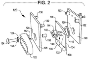
- a latch mechanism 120 can include a handle 122 and an eccentric member 132.
- the handle 122 and eccentric member 132 are fixed relative to one another but rotatable together in the latch mechanism 120.
- the eccentric member 132 is operable like a cam, with the periphery of the eccentric member being defined a major working surface 134 a first long distance 134' from the axis and by minor working surfaces 136 a second shorter distance 136' from the axis 140. Curved working surfaces 138 connect the minor and major working surfaces 136, 134.
- the latch mechanism 120 is illustrated in an unlocked configuration, with the eccentric member 132 pointing sideways.
- the latch mechanism 120 operates by the handle 122 being rotated by a user, and rotating the eccentric member 132 therewith.
- the eccentric member 132 rotates so that the working surfaces 134, 136, 138 alternatingly contact another surface (e.g. support surface 170, see Figures 3 and 4 ).
- the first distance 134' is about 0.635 cm (0.25 inches) greater than the second distance 136', such that the eccentric member 132 causes a displacement of the passenger article of at least 0.635 cm (0.25 inches) when rotated from the unlocked configuration to the locked configuration.
- the first distance 136' may be approximately 1.25" and the second distance 134' may be approximately 1.5".
- the first and second distances 134' and 136' may vary in length depending on the specific geometry of the eccentric member, provided the first distance 134' is longer than the second distance 136'. In some cases, the first distance 134' may be more than 0.635 cm (0.25 inches) longer than the second distance 136". For example, in some specific embodiments, the first distance 134' is at least 1,27 cm (0.5 inches) longer than the second distance 136". In some cases, the eccentric member 226 may be rotated to an unlocked configuration from a locked configuration by rotating the eccentric member in either direction, i.e. an eccentric member can have two minor working surfaces 136 disposed perpendicular to the major working surface 134 to either side.
- the latch mechanism 120 includes the handle 122 and the eccentric member 132 which are connected together by way of a connector 154.
- the handle 122 and eccentric member 132 can be rotatingly fixed together by, e.g., a tooth 142 and slot 144 aligned offset from the handle axis 124 and eccentric member axis 140.
- the handle 122 and eccentric member 132 can be supported between two or more (first and second) supports 126 and 148 with through-holes 128 and 150 therethrough, such that the handle and eccentric member can rotate together relative to the support plates.
- the connector 154 can be a pin, bolt, screw, or any comparable connector.
- the connector 154 can be supported by, e.g., a washer 156 and/or a sleeve 158 for enabling attachment of the handle 122 with the eccentric member 132.
- the latch mechanism 120 can also employ one or more spacers 146, which may include friction-reducing members and/or friction reducing materials, for positioning the eccentric member 132 between the supports 126, 148.
- the supports 126, 148 can be attachable together, e.g. by attachment features 130, 152.
- the supports 126, 148 are also generally attachable with a passenger article such as the passenger article 110 of Figure 1 .
- attachment features 130, 152 can be configured to also attach the supports 126, 148 with the passenger article 110.
- Figures 3 and 4 illustrate the latch mechanism 120 in conjunction with a support assembly 118 in both an unlocked configuration ( Figure 3 ) and a locked configuration ( Figure 4 ), in accordance with certain embodiments.
- Figure 3 shows a support assembly 118 having support elements 160 that are connected by a support member 168.
- the support elements 160 are further connected with rods 166 for connecting the support assembly 118 with, e.g. a passenger article such as passenger article 110.
- the rods 166 may be fixed to the support elements 160, or may be slidingly attached with the support elements via channels 164.
- the support elements 160 have attachment features 162 for, e.g., rotatably attaching the support assembly 118 with a passenger seat such as passenger seat 102.
- the latch mechanism 120 is shown with eccentric member 132 pointing sideways, such that the major working surface 134 is not in contact with a support surface 170 of the support member 168. In this configuration, one of the minor working surfaces 136 will be in contact with the support surface 170.
- the handle 122 is fixed relative to the eccentric member 132, but the handle and eccentric member are rotatable together relative to the latch assembly 120. The handle 122 can be rotated to cause the eccentric member 132 to rotate, so that the minor working surfaces 136 cease to be in contact with the support surface 170, and so that the curved working surface 138 interacts with the support surface to lift the latch assembly 120 relative to the support assembly 118.
- the latch mechanism 120 is shown with eccentric member 132 pointing down, such that the major working surface 134 is in contact with the support surface 170.
- the locked configuration the latch mechanism 120 is raised relative to the support assembly 118.
- the major working surface 134 comes into contact with the support surface 170 when the eccentric member 132 and handle 122 are oriented vertically.
- the major working surface 134 may be flattened compared with the curved working surfaces 138.
- the major working surface 134 resting on the support surface 170 can cause the latch mechanism to resist rotation of the handle 122 and eccentric member 132.
- the latch mechanism 120 shown in Figures 1-4 the latch mechanism is stable when locked or unlocked due to, at least in part, the interaction of the flattened major and minor working surfaces 134, 136 with the support surface 170.
- other means of providing stability are possible, as will be shown with reference to Figures 5-9 , below.
- a passenger article assembly 200 including a second example of a latch mechanism 220 which can include a handle 222 and an eccentric member 226.
- the latch mechanism 220 can be operated in a manner similar to the operation of the latch mechanism 120 shown above in Figures 1-4 .
- the handle 222 and eccentric member 226 are fixed relative to one another and rotatable relative to the latch mechanism 220, such that the eccentric member 226 can be rotated by a user by rotating the handle 222.
- the second exemplary latch mechanism 220 provides for added stability in its locked and unlocked configurations by, e.g., the interaction of a spindle 250 and a support block 240.
- the spindle 250 differs from the connector 154 in that the spindle 250 passes through the eccentric member 226 to interact with the support block 240.
- the latch mechanism 220 includes the handle 222 and eccentric member 226 which are fixed relative to one another.
- the handle 222 and eccentric member 226 may be connected together by way of spindle 250.
- the spindle 250 can pass through an axis 224 of the handle 222 and the eccentric member 226.
- the handle 222 may be connected with the spindle 250 by any suitable connector, such as a first pin 252 which may be inserted through the handle 222 and into a first receiving hole 254 in the spindle 250.
- the eccentric member 226 can have one or more minor surfaces 230 a short distance 230' from the spindle 250, and one or more major surfaces 228 spaced a longer distance 228' from the spindle, and one or more curved working surfaces 232 that connect the minor and major working surfaces.
- the latch mechanism 220 is shown in an unlocked configuration in Figure 5 , with a minor working surface 230 facing down and the major working surface 228 facing to one side.
- the latch mechanism 220 can be actuated by causing the eccentric member 226 to rotate, such that the major working surface 228 moves until it is facing down, and the minor working surface 230 moves until it is facing to one side.
- the latch mechanism 220 can include various features for connecting the handle 222 and eccentric member 226 with a passenger article 110, in accordance with embodiments.
- the spindle 250 may be sized to extend through the eccentric member 226.
- the spindle 250 may further extend through a through-hole 238 in a mounting element 234 which is connectible with an article such as the passenger article 110.
- the mounting element 234 may be attachable via connecting features 236, which may include through-holes for bolts, screws, pins, or any other suitable connector for attaching the mounting element 234 with the passenger article 110.
- a support block 240 may be positioned opposite the mounting element 234.
- the support block 240 may be inserted into, connected with, or partially formed of the mounting element 234 in various embodiments.
- the support block 240 can include a through-hole 246 for receiving the spindle 250, as well as one or more blocking regions 242 and non-blocking regions 244 which may be separated by grooves 248 therebetween.
- the blocking and non-blocking regions 242, 244 are arranged to interact with the spindle 150 by way of, e.g., a second pin 264.
- the second pin 264 may be inserted into a second through-hole 256 of the spindle 250, so that rotating the spindle (e.g.
- the handle 222 causes the second pin 264 to rotate from being in contact with one of the blocking regions 240 across a non-blocking region 242 and into contact with a different one of the blocking regions 240.
- the second pin 264 can be caused to be biased against the support block 240 by mechanical force.
- a spring 260 and washers 258, 262 may be used to impart mechanical force between the second pin 264 and the support block 240.
- any comparable means may be used to bias the support block 240 against the second pin 264.
- any suitable positive feature may be substituted for the second pin 264.
- the operation of the support block 240 and second pin 264 will be discussed further with reference to Figures 8 and 9 .
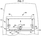
- Figures 6 and 7 illustrate the passenger article assembly 200 in conjunction with a support assembly 118 and seat shroud 104 in both an unlocked configuration ( Figure 6 ) and a locked configuration ( Figure 7 ).
- the passenger article assembly 200 is visible in a front view mounted adjacent to seat shroud 104.
- the seat shroud includes a receiving element such as a pocket 108 defined therein by a lip 106 that overhangs the pocket.
- the passenger article assembly 110 is shown upright, but not locked into the pocket 108; and in Figure 7 , the passenger article assembly is locked into the pocket.
- the latch mechanism 220 is shown in the unlocked configuration.
- the eccentric member 226 In the unlocked configuration, the eccentric member 226 is positioned with a minor working surface 230 positioned abutting the support surface 170 of the support assembly 118 and with the major working surface 228 facing to one side.
- the handle 222 is shown also positioned sideways; however it will be understood that the handle may have any arbitrary orientation with respect to the eccentric member 226 provided they are mechanically linked.
- a cover 202 may be positioned between the handle 222 and eccentric member 226.
- the latch mechanism 220 may be actuated by rotating the handle 222 in order to rotate the eccentric member 226.
- the latch mechanism 220 is shown in the locked configuration.
- the eccentric member 226 is positioned vertically, i.e. with the major working surface 228 abutting the support surface 170.
- the major working surface 228, being farther from the axis 224, causes the latch mechanism 220 to be supported farther from the support surface 170 in the locked configuration than it is in the unlocked configuration (see Figure 6 ).
- the increased separation causes the latch mechanism 220 to press the passenger article assembly 200 upward, pushing the passenger article 110 up into the pocket 108 in the seat shroud 104 and behind the lip 106.
- the passenger article 110 may be slid upward along connecting features such as rods 166 connected with the support elements 160 of the support assembly 118.
- the passenger article 110 may be connected with the support assembly 118 via any other suitable sliding connector such as a rail, slot, or groove; via a swiveling or rotating connector; or other comparable connector.
- the lip 106 prevents the passenger article 110 from falling outward toward a user when the passenger article assembly 200 is stowed and locked.
- Figures 8 and 9 show rear views of the latch mechanism 220 of Figures 5-7 , showing with particularity the interaction of a support block 240 with the second pin 262 of the latch mechanism in an unlocked position, in accordance with some embodiments.
- the unlocked configuration of the latch mechanism 220 in this example is similar to the configuration of the latch mechanism 220 as shown in Figure 6 .
- the support block 240 is mounted to the mounting element 234 such that the support block 240 does not rotate relative to the mounting element. It will be understood that in alternative embodiments, the support block 240 may be integrated with, or formed of, the mounting element 234 without being a separate component.
- the support block 240 includes at least one blocking region 242 which is formed of a protruding section of the support block.
- the support block further includes at least one non-blocking region 244.
- Grooves 248 may be disposed at boundaries of each non-blocking region 244 adjacent to the blocking region(s).
- the grooves 248 are sized and positioned to interact with the spindle 250. For example, the grooves 248 can receive a second pin 264 that protrudes from the spindle 250, or may receive any other suitable element connected with or projecting from the spindle.
- the eccentric member 226 is arranged with the major working surface 228 facing to one side and a minor working surface 230 arranged abutting a support surface 170.
- the spindle 250 protrudes from the support block 240 at a center of the support block and between the blocking and non-blocking regions 242, 244.
- the spindle 250 can have a second pin 264 disposed therein, protruding from one or more sides of the spindle 250.
- a spindle 250 may possess any suitable or comparable positive surface feature.
- the eccentric member 226 is rotated relative to the mounting element 234, e.g. by a user rotating the handle 222, or by other suitable means.
- the spindle 250 also rotates.
- the second pin 248 is at least partly embedded in one of the grooves 248, such that rotating the eccentric member 226 or handle 222 requires overcoming a resisting force caused by the second pin 248 interacting with the grooves 248.
- the second pin 248 will cross over one of the non-blocking regions 244 as the spindle 250 rotates and as the latch mechanism 220 is moved toward the locking configuration.
- the spindle can rotate through only a prescribed arc 266 due to the second pin 262 interacting with the blocking regions 242.
- the prescribed arc 266 is about 90 degrees.
- various configurations of blocking regions and non-blocking regions 242, 244 are possible, which may define prescribed arcs 266 of any suitable range.
- Figure 9 shows a rear view of the latch mechanism 220 of Figures 5-8 , showing with particularity the interaction of a support block 240 with the second pin 262 of the latch mechanism in a locked position.
- the eccentric member 226 is rotated into the locked position (see also Figure 7 )
- the major working surface 228 of the eccentric member 226 is pressed into contact with the support surface 170.
- moving the eccentric member 226 into the locking position will cause the spindle, and concomitantly the mounting element 234 and any attached passenger article to be pressed upward away from the support surface 170.
- the eccentric member 226 can be rotated by a user, e.g. by rotation of the connected handle 222, to alternatingly place the latch mechanism 220 into an unlocked or locked configuration.
- operating the latch mechanism 220 may require that the second pin 264 be unseated from a groove 248, e.g. by pressing on the spindle 250 by way of pressing on the handle 222.
- the grooves 248 are shallow compared to a diameter of the second pin 264, the grooves and second pin may interact to provide some resistance to rotation of the handle 222 without preventing the rotation.
- FIG 10 shows a perspective view of an alternative eccentric member 320 for use with a latch mechanism, such as the latch mechanisms 120 or 220 of Figure 2 or Figure 5 .
- the eccentric member 320 similar to eccentric members 120 or 220 ( Figures 2 or 5 ) has an axis 340 that rotatingly receives a connector such as a spindle, pin, bolt, or other suitable connector.
- the eccentric member 320 has a body 326 and a cam-like periphery 380 defining a major working surface 328 a long, first distance 328' from the axis 340; and a minor working surface 330 a shorter second distance 330' from the axis than the major working surface.
- One or more curved working surfaces 332 connect the major and minor working surfaces 328 and 330 around the periphery 380.
- the eccentric member 320 may be relatively thin, e.g. less than 0.635 cm (0.25 inches) thick, or less than 0.508 cm (0.2 inches), 0.381 cm (0.15 inches), 0.254 cm (0.1 inches), 0.127 cm (0.05 inches), or comparably thin, e.g. when the eccentric member is a stamped sheet metal part or comparable stamped part.
- a total thickness 382 of the eccentric member 320 may be enhanced by the addition of a stack 374 of spacers 376, 378.
- a single spacer 376 may be assembled with the eccentric member 320, but in other cases, a plurality of additional spacers 378 may be further added to the eccentric member 320 to contribute to the total thickness 382.
- the spacer(s) 376, 378 are shaped to match at least a portion of the periphery 380 of the spacer 320 without interfering with the axis 340 or other components.
- the spacer(s) 376, 378 may be connected with the eccentric member body 326 by any suitable connecting method, such as welding, adhesive, bolts, screws, pins, rivets, or comparable methods.
- a rivet 370 has been inserted through a second through-hole 372 in the eccentric member 320 in order to align and connect the spacer(s) 376, 378.
Landscapes
- Engineering & Computer Science (AREA)
- Transportation (AREA)
- Mechanical Engineering (AREA)
- Aviation & Aerospace Engineering (AREA)
- Vehicle Step Arrangements And Article Storage (AREA)
- Seats For Vehicles (AREA)
Description
- The field of the invention relates to latching mechanisms for securing accessories such as tray tables in passenger seats or facing passenger seats.
- Safety is the paramount design criteria for passenger amenities, particularly in the context of aircraft furnishings. For example, amenities should not contribute to traumatic head and neck injury during a high impact event. Related safety standards include the head impact criteria (HIC). During head impact criteria (HIC) testing, it has been found that the tray table facing a passenger seat can contribute to head and neck injuries. If the table creates a lip under the video shroud, the chin of the crash test dummy can catch and cause the head to twist. This is deemed as a failed test. Various strategies have been attempted for solving this issue. For example, a spring loaded table that stowed inside of the video shroud was attempted; however, the table could be deployed by the test dummy during HIC testing when the head would drag on the table and pull it out.
DE102011011657 (RECARO Aircraft Seating GmbH & Co.) relates to a storage surface equipped with a locking unit, in which the locking unit comprises a lifting unit for lifting the storage surface. The lifting unit comprises a rotary knob connected with a rod-shaped support body that contacts a torsion tube below the storage surface on rotation of the rotary knob so as to lift the storage surface. - The general goal is to prevent the head trajectory of a passenger, in the case of crash, from contacting any sharp or protruding edges. As a result, there is a need for a mechanism to prevent the protrusion of accessories such as the tray table and any tray table retention features into the head trajectory of passengers, and to prevent inadvertent deployment of said accessories and features. There is also a general need for such mechanisms to add minimal weight and to be intuitive to operate.
- The terms "invention," "the invention," "this invention" and "the present invention" used in this patent are intended to refer broadly to all of the subject matter of this patent and the patent claims below. Statements containing these terms should be understood not to limit the subject matter described herein or to limit the meaning or scope of the patent claims below. Embodiments of the invention covered by this patent are defined by the claims below, not this summary. This summary is a high-level overview of various aspects of the invention and introduces some of the concepts that are further described in the Detailed Description section below. This summary is not intended to identify key or essential features of the claimed subject matter, nor is it intended to be used in isolation to determine the scope of the claimed subject matter. The subject matter should be understood by reference to appropriate portions of the entire specification of this patent, any or all drawings and each claim.
- The present invention provides a latch mechanism in accordance with claim 1. The present invention correspondingly provides a passenger seat assembly comprising such a latch mechanism, in accordance with claim 12. Further optional features of the invention are presented in the dependent claims. According to certain embodiments of the present disclosure, a latch mechanism is provided that can cause a passenger article to displace relative to a support assembly that supports the passenger article. In embodiments, the latch mechanism includes an eccentric member having an axis and a periphery that is rotatably connected with the latch mechanism. The periphery has a major working surface and a minor working surface, the major working surface being farther from the axis than the minor working surface. When the eccentric member is rotated, the eccentric member can engage with the support assembly such that the eccentric member causes the passenger article to displace relative to the support assembly.
- According to certain embodiments of the present disclosure, a passenger seat assembly is provided that includes a passenger seat, a support assembly connected with the passenger seat; a passenger article supported by the support assembly; and a latch mechanism arranged to interact with the passenger article and the support assembly. The latch mechanism includes an eccentric member connected either the support assembly or the passenger article. The eccentric member can be rotated in the latch mechanism, and has at least one working surface in contact the other of the support assembly and passenger article. When the eccentric member is rotated, the at least one working surface presses against the support assembly or the passenger article, causing the passenger article to displace relative to the support assembly.
- In some embodiments, the latch mechanism is attached with the passenger article, and the at least one working surface of the eccentric member presses against a support surface of the support assembly, so that the latch mechanism moves with the passenger article and presses the passenger article away from the support assembly.
- In some embodiments, the passenger seat includes a seatback shroud with a pocket disposed therein that is configured to at least partially receive the passenger article. Thus, when the passenger article is disposed in an upright position, and the latch mechanism is actuated by rotating the eccentric member, the passenger article can be received within the pocket of the seatback shroud.
- According to certain embodiments of the present disclosure, a method of stowing a passenger article of a passenger seat is provided. The method includes, with the passenger article aligned with a pocket of a seatback shroud of the passenger seat, rotating an eccentric member connected with the passenger article. When the eccentric member is rotated, one or more working surfaces of the eccentric member contact a support surface adjacent with the eccentric member, causing the passenger article and eccentric member to displace relative to the support surface. When the passenger article is displaced away from the support surface it can be at least partially received in the pocket.
- In some embodiments, the method can include rotating the eccentric member from an unlocked position to a locked position. For example, when the eccentric member is rotated, a curved working surface of the periphery of the eccentric member can press against the support surface causing an axis of the eccentric member to displace away from the support surface. When the eccentric member comes to rest in the locked position, a major working surface of the eccentric member comes into contact with the support surface, the major working surface being a greater distance from the axis than the minor working surface.
- Technical descriptions of apparatus, products, and/or methods in the description and/or drawings which are not covered by the claims are presented not as embodiments of the invention but as background art or examples useful for understanding the invention.
-
-
Figure 1 is a perspective view of a latch mechanism for a passenger article mounted to a passenger seat, according to certain embodiments of the present disclosure. -
Figure 2 is an exploded assembly view of a latch mechanism for use with a passenger seat such as the passenger seat shown inFigure 1 . -
Figure 3 is a perspective view of the latch mechanism ofFigure 2 assembled with a passenger article support assembly in an unlocked position. -
Figure 4 is a perspective view of the latch mechanism ofFigures 2 and3 in a locked position. -
Figure 5 is an exploded assembly view of a second latch mechanism for use with a passenger seat such as the passenger seat shown inFigure 1 . -
Figure 6 is a front view of the latch mechanism ofFigure 5 assembled with the aft side of the passenger seat ofFigure 1 in an unlocked position. -
Figure 7 is a front view of the latch mechanism ofFigures 5 and6 assembled with the aft side of the passenger seat ofFigure 1 in a locked position. -
Figure 8 is a back view of the latch mechanism offigures 5-7 in an unlocked position. -
Figure 9 is a back view of the latch mechanism ofFigures 5-8 in a locked position. -
Figure 10 is a perspective view of an alternative eccentric member for use with the latch mechanisms ofFigure 2 orFigure 5 . - The subject matter of embodiments of the present disclosure is described here with specificity to meet statutory requirements, but this description is not necessarily intended to limit the scope of the claims. The claimed subject matter may be embodied in other ways, may include different elements or steps, and may be used in conjunction with other existing or future technologies. This description should not be interpreted as implying any particular order or arrangement among or between various steps or elements except when the order of individual steps or arrangement of elements is explicitly described.
- The described embodiments provide latch mechanisms for passenger seats. While the latch mechanisms are discussed for use with aircraft seats, they are by no means so limited. Rather, embodiments of the latch mechanisms may be used in passenger seats or other seats of any type or otherwise as desired.
- According to certain embodiments, as shown in
Figure 1 , apassenger seat 100 can include apassenger article 110, which may be a tray table, and alatch mechanism 120 for securing the passenger article in a stowed configuration. In various embodiments, apassenger article 110 can include such supportive devices as, e.g., a tray table, a drink holder, a platform for passenger electronics or reading materials, a support for stowing or supporting passenger items, or any comparable article. Thepassenger seat 100 includesseat assembly 102, aseat shroud 104 and apocket 108 in the shroud defined by alip 106 that overhangs the pocket. Asupport assembly 118 is connected with theseat assembly 102 and is generally able to support thepassenger article 110 such that it can rotate outward away from theseat 100. Thepocket 108 is sized to accommodate part of apassenger article 110. In some cases, thepassenger article 110 can have a shaped design configured to interact with thepocket 108. For example, thepassenger article 110 can have amain portion 112 and anarrow portion 114 defined by astep 116. Thenarrow portion 114 may be sized and positioned such that, when thepassenger article 110 is slid upward into thepocket 108, thestep 116 and thelip 106 of the pocket are placed proximate to one another. Parts herein described such as theseat shroud 104,passenger article 110,support assembly 118, and other parts, may be formed of materials including but not limited to aluminum, stainless steel, aramid fibers, polycarbonate, polypropylene, other metallic materials, composite materials, or other similar materials. - The
passenger article 110 is connected with thepassenger seat 100 by asupport assembly 118. Generally, thesupport assembly 118 allows thepassenger article 110 to rotate outward from theseat shroud 104 in order to deploy over the lap of a user. Thepassenger article 110 can be stowed by lifting and rotating the passenger article back up toward theseat shroud 104. Generally, thesupport assembly 118 also allows thepassenger article 110 to slide at least a short distance outward from thesupport assembly 118. Thelatch mechanism 120 is connected with thepassenger article 110 and interacts with thesupport assembly 118. Thus, when thepassenger article 110 is positioned against theseat shroud 104, the passenger article can be slid upward so that at least a portion, e.g. thenarrow portion 114, of the passenger article can fit into thepocket 108 to secure the passenger article in place. In particular, thepassenger article 110 can be secured in thepocket 108 when a user actuates thelatch mechanism 120, e.g. by rotating ahandle 122 of the latch mechanism. The specific means by which thelatch mechanism 120 operates to lift thepassenger article 110 will be better understood with reference toFigures 2-9 below. - The
latch mechanism 120 can support thepassenger article 110 in a raised or locked position partially inserted in thepocket 108. When thepassenger article 110 is stored and locked, the passenger article does not protrude into the head path of a passenger. In particular, a transition from theshroud 104 to thepassenger article 110, moving from top to bottom, does not include any horizontal protrusions that could block the motion of a passenger. Further, in either the locked or unlocked configurations, thelatch mechanism 120 is generally below a level of the motion of a passenger's head in the event of a sudden deceleration. - In some embodiments, as shown in
Figure 2 , alatch mechanism 120 can include ahandle 122 and aneccentric member 132. Thehandle 122 andeccentric member 132 are fixed relative to one another but rotatable together in thelatch mechanism 120. Theeccentric member 132 is operable like a cam, with the periphery of the eccentric member being defined a major working surface 134 a first long distance 134' from the axis and by minor working surfaces 136 a second shorter distance 136' from theaxis 140. Curved workingsurfaces 138 connect the minor and major workingsurfaces latch mechanism 120 is illustrated in an unlocked configuration, with theeccentric member 132 pointing sideways. Thelatch mechanism 120 operates by thehandle 122 being rotated by a user, and rotating theeccentric member 132 therewith. When thelatch mechanism 120 is actuated, theeccentric member 132 rotates so that the workingsurfaces support surface 170, seeFigures 3 and 4 ). In some embodiments, the first distance 134' is about 0.635 cm (0.25 inches) greater than the second distance 136', such that theeccentric member 132 causes a displacement of the passenger article of at least 0.635 cm (0.25 inches) when rotated from the unlocked configuration to the locked configuration. For example, the first distance 136' may be approximately 1.25" and the second distance 134' may be approximately 1.5". The first and second distances 134' and 136' may vary in length depending on the specific geometry of the eccentric member, provided the first distance 134' is longer than the second distance 136'. In some cases, the first distance 134' may be more than 0.635 cm (0.25 inches) longer than thesecond distance 136". For example, in some specific embodiments, the first distance 134' is at least 1,27 cm (0.5 inches) longer than thesecond distance 136". In some cases, theeccentric member 226 may be rotated to an unlocked configuration from a locked configuration by rotating the eccentric member in either direction, i.e. an eccentric member can have two minor workingsurfaces 136 disposed perpendicular to the major workingsurface 134 to either side. - In some specific embodiments, the
latch mechanism 120 includes thehandle 122 and theeccentric member 132 which are connected together by way of aconnector 154. Thehandle 122 andeccentric member 132 can be rotatingly fixed together by, e.g., atooth 142 and slot 144 aligned offset from thehandle axis 124 andeccentric member axis 140. Thehandle 122 andeccentric member 132 can be supported between two or more (first and second) supports 126 and 148 with through-holes connector 154 can be a pin, bolt, screw, or any comparable connector. Theconnector 154 can be supported by, e.g., awasher 156 and/or asleeve 158 for enabling attachment of thehandle 122 with theeccentric member 132. Thelatch mechanism 120 can also employ one ormore spacers 146, which may include friction-reducing members and/or friction reducing materials, for positioning theeccentric member 132 between thesupports supports supports passenger article 110 ofFigure 1 . For example, attachment features 130, 152 can be configured to also attach thesupports passenger article 110. -
Figures 3 and 4 illustrate thelatch mechanism 120 in conjunction with asupport assembly 118 in both an unlocked configuration (Figure 3 ) and a locked configuration (Figure 4 ), in accordance with certain embodiments.Figure 3 shows asupport assembly 118 havingsupport elements 160 that are connected by asupport member 168. Thesupport elements 160 are further connected withrods 166 for connecting thesupport assembly 118 with, e.g. a passenger article such aspassenger article 110. Therods 166 may be fixed to thesupport elements 160, or may be slidingly attached with the support elements viachannels 164. Thesupport elements 160 have attachment features 162 for, e.g., rotatably attaching thesupport assembly 118 with a passenger seat such aspassenger seat 102. - In
Figure 3 , thelatch mechanism 120 is shown witheccentric member 132 pointing sideways, such that the major workingsurface 134 is not in contact with asupport surface 170 of thesupport member 168. In this configuration, one of the minor workingsurfaces 136 will be in contact with thesupport surface 170. Thehandle 122 is fixed relative to theeccentric member 132, but the handle and eccentric member are rotatable together relative to thelatch assembly 120. Thehandle 122 can be rotated to cause theeccentric member 132 to rotate, so that the minor workingsurfaces 136 cease to be in contact with thesupport surface 170, and so that thecurved working surface 138 interacts with the support surface to lift thelatch assembly 120 relative to thesupport assembly 118. - In
Figure 4 , thelatch mechanism 120 is shown witheccentric member 132 pointing down, such that the major workingsurface 134 is in contact with thesupport surface 170. In this configuration, which may be referred to as the locked configuration, thelatch mechanism 120 is raised relative to thesupport assembly 118. The major workingsurface 134 comes into contact with thesupport surface 170 when theeccentric member 132 and handle 122 are oriented vertically. The major workingsurface 134 may be flattened compared with the curved working surfaces 138. When thelatch mechanism 120 is in the locked configuration, the major workingsurface 134 resting on thesupport surface 170 can cause the latch mechanism to resist rotation of thehandle 122 andeccentric member 132. In theexemplary latch mechanism 120 shown inFigures 1-4 , the latch mechanism is stable when locked or unlocked due to, at least in part, the interaction of the flattened major and minor workingsurfaces support surface 170. However, other means of providing stability are possible, as will be shown with reference toFigures 5-9 , below. - In
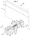
Figure 5 , apassenger article assembly 200 including a second example of alatch mechanism 220 is shown which can include ahandle 222 and aneccentric member 226. Thelatch mechanism 220 can be operated in a manner similar to the operation of thelatch mechanism 120 shown above inFigures 1-4 . For example, thehandle 222 andeccentric member 226 are fixed relative to one another and rotatable relative to thelatch mechanism 220, such that theeccentric member 226 can be rotated by a user by rotating thehandle 222. Unlikelatch mechanism 120, the secondexemplary latch mechanism 220 provides for added stability in its locked and unlocked configurations by, e.g., the interaction of aspindle 250 and asupport block 240. Thespindle 250 differs from theconnector 154 in that thespindle 250 passes through theeccentric member 226 to interact with thesupport block 240. - The
latch mechanism 220 includes thehandle 222 andeccentric member 226 which are fixed relative to one another. In some cases, thehandle 222 andeccentric member 226 may be connected together by way ofspindle 250. Thespindle 250 can pass through anaxis 224 of thehandle 222 and theeccentric member 226. Thehandle 222 may be connected with thespindle 250 by any suitable connector, such as afirst pin 252 which may be inserted through thehandle 222 and into afirst receiving hole 254 in thespindle 250. - Like the
eccentric member 132 discussed above in reference toFigures 1-4 , theeccentric member 226 can have one or more minor surfaces 230 a short distance 230' from thespindle 250, and one or moremajor surfaces 228 spaced a longer distance 228' from the spindle, and one or more curved workingsurfaces 232 that connect the minor and major working surfaces. Thelatch mechanism 220 is shown in an unlocked configuration inFigure 5 , with aminor working surface 230 facing down and the major workingsurface 228 facing to one side. Thelatch mechanism 220 can be actuated by causing theeccentric member 226 to rotate, such that the major workingsurface 228 moves until it is facing down, and theminor working surface 230 moves until it is facing to one side. - The
latch mechanism 220 can include various features for connecting thehandle 222 andeccentric member 226 with apassenger article 110, in accordance with embodiments. For example, and as also shown inFigure 5 , thespindle 250 may be sized to extend through theeccentric member 226. Thespindle 250 may further extend through a through-hole 238 in a mountingelement 234 which is connectible with an article such as thepassenger article 110. The mountingelement 234 may be attachable via connectingfeatures 236, which may include through-holes for bolts, screws, pins, or any other suitable connector for attaching the mountingelement 234 with thepassenger article 110. - A
support block 240 may be positioned opposite the mountingelement 234. Thesupport block 240 may be inserted into, connected with, or partially formed of the mountingelement 234 in various embodiments. Thesupport block 240 can include a through-hole 246 for receiving thespindle 250, as well as one ormore blocking regions 242 andnon-blocking regions 244 which may be separated bygrooves 248 therebetween. The blocking andnon-blocking regions spindle 150 by way of, e.g., asecond pin 264. Thesecond pin 264 may be inserted into a second through-hole 256 of thespindle 250, so that rotating the spindle (e.g. by way of the handle 222) causes thesecond pin 264 to rotate from being in contact with one of the blockingregions 240 across anon-blocking region 242 and into contact with a different one of the blockingregions 240. Thesecond pin 264 can be caused to be biased against thesupport block 240 by mechanical force. For example, aspring 260 andwashers 258, 262 may be used to impart mechanical force between thesecond pin 264 and thesupport block 240. However, it will be understood that any comparable means may be used to bias thesupport block 240 against thesecond pin 264. It will also be understood that any suitable positive feature may be substituted for thesecond pin 264. The operation of thesupport block 240 andsecond pin 264 will be discussed further with reference toFigures 8 and 9 . -
Figures 6 and7 illustrate thepassenger article assembly 200 in conjunction with asupport assembly 118 andseat shroud 104 in both an unlocked configuration (Figure 6 ) and a locked configuration (Figure 7 ). For example, inFigure 6 , thepassenger article assembly 200 is visible in a front view mounted adjacent toseat shroud 104. The seat shroud includes a receiving element such as apocket 108 defined therein by alip 106 that overhangs the pocket. InFigure 6 , thepassenger article assembly 110 is shown upright, but not locked into thepocket 108; and inFigure 7 , the passenger article assembly is locked into the pocket. - In
Figure 6 , thelatch mechanism 220 is shown in the unlocked configuration. In the unlocked configuration, theeccentric member 226 is positioned with aminor working surface 230 positioned abutting thesupport surface 170 of thesupport assembly 118 and with the major workingsurface 228 facing to one side. Thehandle 222 is shown also positioned sideways; however it will be understood that the handle may have any arbitrary orientation with respect to theeccentric member 226 provided they are mechanically linked. In some embodiments, as shown, acover 202 may be positioned between thehandle 222 andeccentric member 226. As discussed above with reference to thelatch mechanism 120 shown inFigures 1-4 , thelatch mechanism 220 may be actuated by rotating thehandle 222 in order to rotate theeccentric member 226. As theeccentric member 226 rotates, one of the curved working surfaces 232 engages thesupport surface 170 of thesupport assembly 118. Thecurved working surface 232, as it engages thesupport surface 170, causes thelatch mechanism 220 to move up and away from thesupport member 168 of thesupport assembly 118, and toward a locked configuration as shown inFigure 7 . - In
Figure 7 , thelatch mechanism 220 is shown in the locked configuration. In the locked configuration, theeccentric member 226 is positioned vertically, i.e. with the major workingsurface 228 abutting thesupport surface 170. The major workingsurface 228, being farther from theaxis 224, causes thelatch mechanism 220 to be supported farther from thesupport surface 170 in the locked configuration than it is in the unlocked configuration (seeFigure 6 ). Thus, the increased separation causes thelatch mechanism 220 to press thepassenger article assembly 200 upward, pushing thepassenger article 110 up into thepocket 108 in theseat shroud 104 and behind thelip 106. Thepassenger article 110 may be slid upward along connecting features such asrods 166 connected with thesupport elements 160 of thesupport assembly 118. In various embodiments, thepassenger article 110 may be connected with thesupport assembly 118 via any other suitable sliding connector such as a rail, slot, or groove; via a swiveling or rotating connector; or other comparable connector. Thelip 106 prevents thepassenger article 110 from falling outward toward a user when thepassenger article assembly 200 is stowed and locked. -
Figures 8 and 9 show rear views of thelatch mechanism 220 ofFigures 5-7 , showing with particularity the interaction of asupport block 240 with thesecond pin 262 of the latch mechanism in an unlocked position, in accordance with some embodiments. The unlocked configuration of thelatch mechanism 220 in this example is similar to the configuration of thelatch mechanism 220 as shown inFigure 6 . - The
support block 240 is mounted to the mountingelement 234 such that thesupport block 240 does not rotate relative to the mounting element. It will be understood that in alternative embodiments, thesupport block 240 may be integrated with, or formed of, the mountingelement 234 without being a separate component. Thesupport block 240 includes at least one blockingregion 242 which is formed of a protruding section of the support block. The support block further includes at least onenon-blocking region 244.Grooves 248 may be disposed at boundaries of eachnon-blocking region 244 adjacent to the blocking region(s). Thegrooves 248 are sized and positioned to interact with thespindle 250. For example, thegrooves 248 can receive asecond pin 264 that protrudes from thespindle 250, or may receive any other suitable element connected with or projecting from the spindle. - As shown in
Figure 8 , theeccentric member 226 is arranged with the major workingsurface 228 facing to one side and aminor working surface 230 arranged abutting asupport surface 170. Thespindle 250 protrudes from thesupport block 240 at a center of the support block and between the blocking andnon-blocking regions spindle 250 can have asecond pin 264 disposed therein, protruding from one or more sides of thespindle 250. In some cases, in lieu of thesecond pin 248, aspindle 250 may possess any suitable or comparable positive surface feature. - In operation, the
eccentric member 226 is rotated relative to the mountingelement 234, e.g. by a user rotating thehandle 222, or by other suitable means. As theeccentric member 226 rotates, thespindle 250 also rotates. In some cases, thesecond pin 248 is at least partly embedded in one of thegrooves 248, such that rotating theeccentric member 226 or handle 222 requires overcoming a resisting force caused by thesecond pin 248 interacting with thegrooves 248. Thesecond pin 248 will cross over one of thenon-blocking regions 244 as thespindle 250 rotates and as thelatch mechanism 220 is moved toward the locking configuration. Thus, the spindle can rotate through only aprescribed arc 266 due to thesecond pin 262 interacting with the blockingregions 242. In some embodiments, theprescribed arc 266 is about 90 degrees. However, various configurations of blocking regions andnon-blocking regions prescribed arcs 266 of any suitable range. -
Figure 9 shows a rear view of thelatch mechanism 220 ofFigures 5-8 , showing with particularity the interaction of asupport block 240 with thesecond pin 262 of the latch mechanism in a locked position. As theeccentric member 226 is rotated into the locked position (see alsoFigure 7 ), the major workingsurface 228 of theeccentric member 226 is pressed into contact with thesupport surface 170. As the major workingsurface 228 is farther from thespindle 250 than the minor workingsurface 230, moving theeccentric member 226 into the locking position will cause the spindle, and concomitantly the mountingelement 234 and any attached passenger article to be pressed upward away from thesupport surface 170. - In operation, the
eccentric member 226 can be rotated by a user, e.g. by rotation of the connectedhandle 222, to alternatingly place thelatch mechanism 220 into an unlocked or locked configuration. In some cases, operating thelatch mechanism 220 may require that thesecond pin 264 be unseated from agroove 248, e.g. by pressing on thespindle 250 by way of pressing on thehandle 222. In some other cases, e.g. if thegrooves 248 are shallow compared to a diameter of thesecond pin 264, the grooves and second pin may interact to provide some resistance to rotation of thehandle 222 without preventing the rotation. -
Figure 10 shows a perspective view of an alternativeeccentric member 320 for use with a latch mechanism, such as thelatch mechanisms Figure 2 orFigure 5 . Theeccentric member 320, similar toeccentric members 120 or 220 (Figures 2 or5 ) has anaxis 340 that rotatingly receives a connector such as a spindle, pin, bolt, or other suitable connector. Theeccentric member 320 has abody 326 and a cam-like periphery 380 defining a major working surface 328 a long, first distance 328' from theaxis 340; and a minor working surface 330 a shorter second distance 330' from the axis than the major working surface. One or more curved workingsurfaces 332 connect the major and minor workingsurfaces periphery 380. - In some cases, the
eccentric member 320 may be relatively thin, e.g. less than 0.635 cm (0.25 inches) thick, or less than 0.508 cm (0.2 inches), 0.381 cm (0.15 inches), 0.254 cm (0.1 inches), 0.127 cm (0.05 inches), or comparably thin, e.g. when the eccentric member is a stamped sheet metal part or comparable stamped part. Thus, atotal thickness 382 of theeccentric member 320 may be enhanced by the addition of astack 374 ofspacers single spacer 376 may be assembled with theeccentric member 320, but in other cases, a plurality ofadditional spacers 378 may be further added to theeccentric member 320 to contribute to thetotal thickness 382. The spacer(s) 376, 378 are shaped to match at least a portion of theperiphery 380 of thespacer 320 without interfering with theaxis 340 or other components. The spacer(s) 376, 378 may be connected with theeccentric member body 326 by any suitable connecting method, such as welding, adhesive, bolts, screws, pins, rivets, or comparable methods. For example, as shown inFigure 10 , arivet 370 has been inserted through a second through-hole 372 in theeccentric member 320 in order to align and connect the spacer(s) 376, 378. - Different arrangements of the components depicted in the drawings or described above, as well as components and steps not shown or described are possible. Similarly, some features and sub-combinations are useful and may be employed without reference to other features and sub-combinations. Embodiments of the invention have been described for illustrative and not restrictive purposes, and alternative embodiments will become apparent to readers of this patent. Accordingly, the present invention is not limited to the embodiments described above or depicted in the drawings, and various embodiments and modifications may be made without departing from the scope of the claims below.
Claims (16)
- A latch mechanism (120, 220), comprising:a support assembly (118) that supports a passenger article (110) and allows the passenger article (110) to move with respect to the support assembly (118); andan eccentric member (132, 226, 320) having an axis (140, 224, 340) and a periphery (380), the periphery (380) comprising a major working surface (134, 228, 328) and a minor working surface (136, 230, 330), the major working surface (134, 228, 328) being farther from the axis (140, 224, 340) than the minor working surface (136, 230, 330); wherein the eccentric member (132, 226, 320) is configured to be rotatingly connected with the passenger article (110) and arranged to engage with the support assembly (118) such that, when the eccentric member (132, 226, 320) is rotated, the eccentric member (132, 226, 320) causes the passenger article (110) to displace relative to the support assembly (118); wherein the latch mechanism (120, 220) further comprises a handle (122, 222) connected to the eccentric member (132, 226, 320) such that, when the handle (122, 222) is rotated, the eccentric member (132, 226, 320) is rotated with the handle (122, 222);characterised in that the handle (122, 222) is connected to the eccentric member (132, 226, 320) by a connector (154, 250) rotatingly received in the eccentric member axis (140, 224, 340).
- The latch mechanism (120, 220) of claim 1, wherein the handle (122, 222) is connected to the eccentric member (132, 226, 320) by any one of a pin, bolt, screw or a spindle (154, 250).
- The latch mechanism (120, 220) of claim 2, wherein the spindle (250) connected with the eccentric member (132, 226, 320) is configured to interact with one or more blocking regions (242) and one or more non-blocking regions (244), such that the spindle (250) can rotate through a prescribed arc (266) defined by the one or more blocking regions (242) and one or more non-blocking regions (244).
- The latch mechanism (120, 220) of claim 3, wherein the spindle (250) further comprises a pin (264) extending laterally from the spindle (250), and wherein the pin (264) is configured to interact with the one or more blocking regions (242) and one or more non-blocking regions (244).
- The latch mechanism (120, 220) of claim 4, further comprising one or more grooves (248) configured to interact with the pin (264), and wherein the latch mechanism (120, 220) further comprises a means (260) for biasing the pin (264) against the one or more grooves (248) such that the grooves (248) resist rotation of the spindle (250) by way of the pin (264) when the pin (264) is in one of the one or more grooves (248).
- The latch mechanism (120, 220) of any of the preceding claims, wherein the passenger article (110) comprises a tray table.
- The latch mechanism (120, 220) of any of the preceding claims, wherein:the eccentric member (132, 226, 320) is rotatingly connected with a bottom of the passenger article (110) when the passenger article (110) is in an upright position;the support assembly (118) comprises a support surface (170) facing the eccentric member (132, 226, 320); andthe eccentric member (132, 226, 320) is in contact with the support surface (170).
- The latch mechanism (120, 220) of any of the preceding claims, comprising an unlocked configuration and a locked configuration, wherein:in the unlocked configuration, the minor working surface (136, 230, 330) of the eccentric member (132, 226, 320) is in contact with the support assembly (118); andin the locked configuration, the major working surface (134, 228, 328) of the eccentric member (132, 226, 320) is in contact with the support assembly (118).
- The latch mechanism (120, 220) of any of the preceding claims, further comprising a mounting element (234) that receives the eccentric member (132, 226, 320), the eccentric member (132, 226, 320) being rotatingly connected with the mounting element (234), and the mounting element (234) being configured to connect with the passenger article (110).
- The latch mechanism (120, 220) of any of the preceding claims, wherein the eccentric member (132, 226, 320) further comprises a curved working surface disposed at a periphery of the eccentric member (132, 226, 320) between the major working surface (134, 228, 328) and the minor working surface (136, 230, 330), the curved working surface being configured to cause the eccentric member (132, 226, 320) to displace relative to the support assembly(118) when the eccentric member (132, 226, 320) is rotated.
- The latch mechanism (120, 220) of any of the preceding claims, wherein the eccentric member (132, 226, 320) comprises a primary structural part (326) having a first thickness, and further comprising:
one or more spacing parts (376, 378) connected with the primary structural part, the one or more spacing parts each having a major working edge and a minor working edge, each major working edge configured to align with the major working surface (134, 228, 328) of the periphery (380) of the eccentric member (132, 226, 320), and each minor working edge configured to align with the minor working surface (136, 230, 330) of the eccentric member (132, 226, 320), such that the combined primary structural part and one or more spacing parts has a combined thickness (382) greater than the first thickness. - A passenger seat assembly, comprising:a passenger seat (100, 102);a support assembly (118) connected with the passenger seat (100, 102);a passenger article (110) supported by the support assembly (118); anda latch mechanism (120, 220) as defined in any of the preceding claims.
- The passenger seat assembly of claim 12, further comprising a seatback shroud (104) connected with the passenger seat (100, 102), where the seatback shroud (104) comprises a pocket (108) configured to at least partially receive the passenger article (110) such that, when the passenger article (110) is moved when the eccentric member (132, 226, 320) is rotated, the passenger article (100) is at least partially received by the pocket (108).
- The passenger seat assembly of claim 12 or 13, wherein the passenger article (110) is rotatable relative to the support assembly (118) when the passenger article (110) is not received by the pocket (108), and wherein the passenger article (110) is secured in an upright position when the passenger article (110) is at least partially received by the pocket (108).
- The passenger seat assembly of any of claims 12 to 14, wherein the passenger article (110) does not protrude into a head path of a passenger when the passenger article (110) is at least partially received by the pocket (108).
- The passenger seat assembly of any of claims 12 to 15, wherein the latch mechanism (120, 220) is positioned below a head path of a passenger.
Applications Claiming Priority (2)
| Application Number | Priority Date | Filing Date | Title |
|---|---|---|---|
| US201562263247P | 2015-12-04 | 2015-12-04 | |
| PCT/US2016/041323 WO2017095477A1 (en) | 2015-12-04 | 2016-07-07 | Latch mechanism |
Publications (2)
| Publication Number | Publication Date |
|---|---|
| EP3383700A1 EP3383700A1 (en) | 2018-10-10 |
| EP3383700B1 true EP3383700B1 (en) | 2021-10-13 |
Family
ID=56561460
Family Applications (1)
| Application Number | Title | Priority Date | Filing Date |
|---|---|---|---|
| EP16745926.2A Active EP3383700B1 (en) | 2015-12-04 | 2016-07-07 | Latch mechanism |
Country Status (3)
| Country | Link |
|---|---|
| US (1) | US10710486B2 (en) |
| EP (1) | EP3383700B1 (en) |
| WO (1) | WO2017095477A1 (en) |
Families Citing this family (5)
| Publication number | Priority date | Publication date | Assignee | Title |
|---|---|---|---|---|
| DE102017117173A1 (en) * | 2017-07-28 | 2019-01-31 | Recaro Aircraft Seating Gmbh & Co. Kg | table device |
| US10562635B2 (en) * | 2018-03-19 | 2020-02-18 | The Boeing Company | Personal device carrier and a passenger seat |
| WO2020068064A1 (en) * | 2018-09-26 | 2020-04-02 | Safran Seats Usa Llc | Multi-latch assembly for selective retention of aircraft passenger tray table and/or other deployable components |
| US11834184B2 (en) * | 2022-04-01 | 2023-12-05 | B/E Aerospace, Inc. | Active NIJ reduction devices |
| JP7889299B2 (en) * | 2023-01-13 | 2026-07-14 | トヨタ紡織株式会社 | Locking device for seat back table |
Family Cites Families (7)
| Publication number | Priority date | Publication date | Assignee | Title |
|---|---|---|---|---|
| DE3110130A1 (en) * | 1981-03-16 | 1982-10-14 | Adam Opel AG, 6090 Rüsselsheim | Lock for pivotable backrests of the rear seats of motor vehicles |
| US6619733B2 (en) * | 2001-11-19 | 2003-09-16 | The Boeing Company | Passenger seat headrest platform |
| US6550861B1 (en) * | 2001-11-21 | 2003-04-22 | B E Aerospace, Inc. | Passenger seat meal tray |
| DE102007001962A1 (en) * | 2007-01-13 | 2008-07-17 | Recaro Aircraft Seating Gmbh & Co. Kg | seat device |
| DE102011011657B4 (en) | 2011-02-18 | 2025-11-27 | Recaro Aircraft Seating Gmbh & Co. Kg | Table device |
| US8826830B2 (en) * | 2011-10-13 | 2014-09-09 | Nick Pajic | Tray table with rotatable inner tray for electronic device docking |
| TW201410509A (en) | 2012-09-14 | 2014-03-16 | Superalloy Ind Co Ltd | Seatback dining table device |
-
2016
- 2016-07-07 US US15/779,917 patent/US10710486B2/en active Active
- 2016-07-07 WO PCT/US2016/041323 patent/WO2017095477A1/en not_active Ceased
- 2016-07-07 EP EP16745926.2A patent/EP3383700B1/en active Active
Non-Patent Citations (1)
| Title |
|---|
| None * |
Also Published As
| Publication number | Publication date |
|---|---|
| EP3383700A1 (en) | 2018-10-10 |
| US10710486B2 (en) | 2020-07-14 |
| US20180319306A1 (en) | 2018-11-08 |
| WO2017095477A1 (en) | 2017-06-08 |
Similar Documents
| Publication | Publication Date | Title |
|---|---|---|
| US10710486B2 (en) | Latch mechanism | |
| US10392114B2 (en) | Aircraft seating assembly | |
| US9145209B2 (en) | Rotatable cabin attendant seat and aircraft monument arrangement with a rotatable cabin attendant seat | |
| US10543921B2 (en) | Lightweight seat | |
| EP3303133B1 (en) | Deployable seatback holder for portable electronic devices | |
| EP2686241B1 (en) | Plinth-mounted seat assembly and mounting sub-assemblies | |
| US9315238B2 (en) | Lounge assembly | |
| US20160167555A1 (en) | Tray table assembly | |
| EP3230162B1 (en) | Retractable device holder for an aircraft seat | |
| KR102428155B1 (en) | deployable table assembly | |
| EP1848632B1 (en) | Aircraft luggage compartment | |
| EP3105122B1 (en) | Easy install tray table | |
| EP3350022B1 (en) | Portable electronic device holder for tray tables | |
| EP2560876B1 (en) | Tray table stop assembly | |
| US20200148081A1 (en) | Seat provided with a system for locking the tray table in the event of an impact | |
| US20230182632A1 (en) | Foldable ped holder | |
| EP3283370B1 (en) | Portable electronic device holder | |
| US10870381B2 (en) | Lock assembly | |
| US20220396215A1 (en) | Tape holder for portable electronic device | |
| EP3310658B1 (en) | One-motion table latch | |
| EP4263351B1 (en) | Aircraft seat design with mountable food tray | |
| US10946967B2 (en) | Aircraft seat deployable bridge table, mounting provisions, and storage provisions | |
| EP3486509B1 (en) | Shaft-support structure for rotary body | |
| EP4261132B1 (en) | Implementations of deployable seatback pockets | |
| US20250361016A1 (en) | Latch assembly with sliding latch and rotating catch |
Legal Events
| Date | Code | Title | Description |
|---|---|---|---|
| STAA | Information on the status of an ep patent application or granted ep patent |
Free format text: STATUS: THE INTERNATIONAL PUBLICATION HAS BEEN MADE |
|
| PUAI | Public reference made under article 153(3) epc to a published international application that has entered the european phase |
Free format text: ORIGINAL CODE: 0009012 |
|
| STAA | Information on the status of an ep patent application or granted ep patent |
Free format text: STATUS: REQUEST FOR EXAMINATION WAS MADE |
|
| 17P | Request for examination filed |
Effective date: 20180702 |
|
| AK | Designated contracting states |
Kind code of ref document: A1 Designated state(s): AL AT BE BG CH CY CZ DE DK EE ES FI FR GB GR HR HU IE IS IT LI LT LU LV MC MK MT NL NO PL PT RO RS SE SI SK SM TR |
|
| AX | Request for extension of the european patent |
Extension state: BA ME |
|
| DAV | Request for validation of the european patent (deleted) | ||
| DAX | Request for extension of the european patent (deleted) | ||
| RAP1 | Party data changed (applicant data changed or rights of an application transferred) |
Owner name: SAFRAN SEATS USA LLC |
|
| STAA | Information on the status of an ep patent application or granted ep patent |
Free format text: STATUS: EXAMINATION IS IN PROGRESS |
|
| 17Q | First examination report despatched |
Effective date: 20200806 |
|
| GRAP | Despatch of communication of intention to grant a patent |
Free format text: ORIGINAL CODE: EPIDOSNIGR1 |
|
| STAA | Information on the status of an ep patent application or granted ep patent |
Free format text: STATUS: GRANT OF PATENT IS INTENDED |
|
| INTG | Intention to grant announced |
Effective date: 20210514 |
|
| GRAS | Grant fee paid |
Free format text: ORIGINAL CODE: EPIDOSNIGR3 |
|
| GRAA | (expected) grant |
Free format text: ORIGINAL CODE: 0009210 |
|
| STAA | Information on the status of an ep patent application or granted ep patent |
Free format text: STATUS: THE PATENT HAS BEEN GRANTED |
|
| AK | Designated contracting states |
Kind code of ref document: B1 Designated state(s): AL AT BE BG CH CY CZ DE DK EE ES FI FR GB GR HR HU IE IS IT LI LT LU LV MC MK MT NL NO PL PT RO RS SE SI SK SM TR |
|
| REG | Reference to a national code |
Ref country code: GB Ref legal event code: FG4D |
|
| REG | Reference to a national code |
Ref country code: CH Ref legal event code: EP |
|
| REG | Reference to a national code |
Ref country code: DE Ref legal event code: R096 Ref document number: 602016064888 Country of ref document: DE |
|
| REG | Reference to a national code |
Ref country code: IE Ref legal event code: FG4D |
|
| REG | Reference to a national code |
Ref country code: AT Ref legal event code: REF Ref document number: 1437959 Country of ref document: AT Kind code of ref document: T Effective date: 20211115 |
|
| REG | Reference to a national code |
Ref country code: LT Ref legal event code: MG9D |
|
| REG | Reference to a national code |
Ref country code: NL Ref legal event code: MP Effective date: 20211013 |
|
| REG | Reference to a national code |
Ref country code: AT Ref legal event code: MK05 Ref document number: 1437959 Country of ref document: AT Kind code of ref document: T Effective date: 20211013 |
|
| PG25 | Lapsed in a contracting state [announced via postgrant information from national office to epo] |
Ref country code: RS Free format text: LAPSE BECAUSE OF FAILURE TO SUBMIT A TRANSLATION OF THE DESCRIPTION OR TO PAY THE FEE WITHIN THE PRESCRIBED TIME-LIMIT Effective date: 20211013 Ref country code: LT Free format text: LAPSE BECAUSE OF FAILURE TO SUBMIT A TRANSLATION OF THE DESCRIPTION OR TO PAY THE FEE WITHIN THE PRESCRIBED TIME-LIMIT Effective date: 20211013 Ref country code: FI Free format text: LAPSE BECAUSE OF FAILURE TO SUBMIT A TRANSLATION OF THE DESCRIPTION OR TO PAY THE FEE WITHIN THE PRESCRIBED TIME-LIMIT Effective date: 20211013 Ref country code: BG Free format text: LAPSE BECAUSE OF FAILURE TO SUBMIT A TRANSLATION OF THE DESCRIPTION OR TO PAY THE FEE WITHIN THE PRESCRIBED TIME-LIMIT Effective date: 20220113 Ref country code: AT Free format text: LAPSE BECAUSE OF FAILURE TO SUBMIT A TRANSLATION OF THE DESCRIPTION OR TO PAY THE FEE WITHIN THE PRESCRIBED TIME-LIMIT Effective date: 20211013 |
|
| PG25 | Lapsed in a contracting state [announced via postgrant information from national office to epo] |
Ref country code: IS Free format text: LAPSE BECAUSE OF FAILURE TO SUBMIT A TRANSLATION OF THE DESCRIPTION OR TO PAY THE FEE WITHIN THE PRESCRIBED TIME-LIMIT Effective date: 20220213 Ref country code: SE Free format text: LAPSE BECAUSE OF FAILURE TO SUBMIT A TRANSLATION OF THE DESCRIPTION OR TO PAY THE FEE WITHIN THE PRESCRIBED TIME-LIMIT Effective date: 20211013 Ref country code: PT Free format text: LAPSE BECAUSE OF FAILURE TO SUBMIT A TRANSLATION OF THE DESCRIPTION OR TO PAY THE FEE WITHIN THE PRESCRIBED TIME-LIMIT Effective date: 20220214 Ref country code: PL Free format text: LAPSE BECAUSE OF FAILURE TO SUBMIT A TRANSLATION OF THE DESCRIPTION OR TO PAY THE FEE WITHIN THE PRESCRIBED TIME-LIMIT Effective date: 20211013 Ref country code: NO Free format text: LAPSE BECAUSE OF FAILURE TO SUBMIT A TRANSLATION OF THE DESCRIPTION OR TO PAY THE FEE WITHIN THE PRESCRIBED TIME-LIMIT Effective date: 20220113 Ref country code: NL Free format text: LAPSE BECAUSE OF FAILURE TO SUBMIT A TRANSLATION OF THE DESCRIPTION OR TO PAY THE FEE WITHIN THE PRESCRIBED TIME-LIMIT Effective date: 20211013 Ref country code: LV Free format text: LAPSE BECAUSE OF FAILURE TO SUBMIT A TRANSLATION OF THE DESCRIPTION OR TO PAY THE FEE WITHIN THE PRESCRIBED TIME-LIMIT Effective date: 20211013 Ref country code: HR Free format text: LAPSE BECAUSE OF FAILURE TO SUBMIT A TRANSLATION OF THE DESCRIPTION OR TO PAY THE FEE WITHIN THE PRESCRIBED TIME-LIMIT Effective date: 20211013 Ref country code: GR Free format text: LAPSE BECAUSE OF FAILURE TO SUBMIT A TRANSLATION OF THE DESCRIPTION OR TO PAY THE FEE WITHIN THE PRESCRIBED TIME-LIMIT Effective date: 20220114 Ref country code: ES Free format text: LAPSE BECAUSE OF FAILURE TO SUBMIT A TRANSLATION OF THE DESCRIPTION OR TO PAY THE FEE WITHIN THE PRESCRIBED TIME-LIMIT Effective date: 20211013 |
|
| REG | Reference to a national code |
Ref country code: DE Ref legal event code: R097 Ref document number: 602016064888 Country of ref document: DE |
|
| PG25 | Lapsed in a contracting state [announced via postgrant information from national office to epo] |
Ref country code: SM Free format text: LAPSE BECAUSE OF FAILURE TO SUBMIT A TRANSLATION OF THE DESCRIPTION OR TO PAY THE FEE WITHIN THE PRESCRIBED TIME-LIMIT Effective date: 20211013 Ref country code: SK Free format text: LAPSE BECAUSE OF FAILURE TO SUBMIT A TRANSLATION OF THE DESCRIPTION OR TO PAY THE FEE WITHIN THE PRESCRIBED TIME-LIMIT Effective date: 20211013 Ref country code: RO Free format text: LAPSE BECAUSE OF FAILURE TO SUBMIT A TRANSLATION OF THE DESCRIPTION OR TO PAY THE FEE WITHIN THE PRESCRIBED TIME-LIMIT Effective date: 20211013 Ref country code: EE Free format text: LAPSE BECAUSE OF FAILURE TO SUBMIT A TRANSLATION OF THE DESCRIPTION OR TO PAY THE FEE WITHIN THE PRESCRIBED TIME-LIMIT Effective date: 20211013 Ref country code: DK Free format text: LAPSE BECAUSE OF FAILURE TO SUBMIT A TRANSLATION OF THE DESCRIPTION OR TO PAY THE FEE WITHIN THE PRESCRIBED TIME-LIMIT Effective date: 20211013 Ref country code: CZ Free format text: LAPSE BECAUSE OF FAILURE TO SUBMIT A TRANSLATION OF THE DESCRIPTION OR TO PAY THE FEE WITHIN THE PRESCRIBED TIME-LIMIT Effective date: 20211013 |
|
| PLBE | No opposition filed within time limit |
Free format text: ORIGINAL CODE: 0009261 |
|
| STAA | Information on the status of an ep patent application or granted ep patent |
Free format text: STATUS: NO OPPOSITION FILED WITHIN TIME LIMIT |
|
| 26N | No opposition filed |
Effective date: 20220714 |
|
| PG25 | Lapsed in a contracting state [announced via postgrant information from national office to epo] |
Ref country code: AL Free format text: LAPSE BECAUSE OF FAILURE TO SUBMIT A TRANSLATION OF THE DESCRIPTION OR TO PAY THE FEE WITHIN THE PRESCRIBED TIME-LIMIT Effective date: 20211013 |
|
| PG25 | Lapsed in a contracting state [announced via postgrant information from national office to epo] |
Ref country code: SI Free format text: LAPSE BECAUSE OF FAILURE TO SUBMIT A TRANSLATION OF THE DESCRIPTION OR TO PAY THE FEE WITHIN THE PRESCRIBED TIME-LIMIT Effective date: 20211013 |
|
| PG25 | Lapsed in a contracting state [announced via postgrant information from national office to epo] |
Ref country code: MC Free format text: LAPSE BECAUSE OF FAILURE TO SUBMIT A TRANSLATION OF THE DESCRIPTION OR TO PAY THE FEE WITHIN THE PRESCRIBED TIME-LIMIT Effective date: 20211013 |
|
| REG | Reference to a national code |
Ref country code: CH Ref legal event code: PL |
|
| REG | Reference to a national code |
Ref country code: BE Ref legal event code: MM Effective date: 20220731 |
|
| PG25 | Lapsed in a contracting state [announced via postgrant information from national office to epo] |
Ref country code: LU Free format text: LAPSE BECAUSE OF NON-PAYMENT OF DUE FEES Effective date: 20220707 Ref country code: LI Free format text: LAPSE BECAUSE OF NON-PAYMENT OF DUE FEES Effective date: 20220731 Ref country code: CH Free format text: LAPSE BECAUSE OF NON-PAYMENT OF DUE FEES Effective date: 20220731 |
|
| PG25 | Lapsed in a contracting state [announced via postgrant information from national office to epo] |
Ref country code: IT Free format text: LAPSE BECAUSE OF FAILURE TO SUBMIT A TRANSLATION OF THE DESCRIPTION OR TO PAY THE FEE WITHIN THE PRESCRIBED TIME-LIMIT Effective date: 20211013 Ref country code: BE Free format text: LAPSE BECAUSE OF NON-PAYMENT OF DUE FEES Effective date: 20220731 |
|
| PG25 | Lapsed in a contracting state [announced via postgrant information from national office to epo] |
Ref country code: IE Free format text: LAPSE BECAUSE OF NON-PAYMENT OF DUE FEES Effective date: 20220707 |
|
| PG25 | Lapsed in a contracting state [announced via postgrant information from national office to epo] |
Ref country code: HU Free format text: LAPSE BECAUSE OF FAILURE TO SUBMIT A TRANSLATION OF THE DESCRIPTION OR TO PAY THE FEE WITHIN THE PRESCRIBED TIME-LIMIT; INVALID AB INITIO Effective date: 20160707 |
|
| PG25 | Lapsed in a contracting state [announced via postgrant information from national office to epo] |
Ref country code: MK Free format text: LAPSE BECAUSE OF FAILURE TO SUBMIT A TRANSLATION OF THE DESCRIPTION OR TO PAY THE FEE WITHIN THE PRESCRIBED TIME-LIMIT Effective date: 20211013 Ref country code: CY Free format text: LAPSE BECAUSE OF FAILURE TO SUBMIT A TRANSLATION OF THE DESCRIPTION OR TO PAY THE FEE WITHIN THE PRESCRIBED TIME-LIMIT Effective date: 20211013 |
|
| PG25 | Lapsed in a contracting state [announced via postgrant information from national office to epo] |
Ref country code: TR Free format text: LAPSE BECAUSE OF FAILURE TO SUBMIT A TRANSLATION OF THE DESCRIPTION OR TO PAY THE FEE WITHIN THE PRESCRIBED TIME-LIMIT Effective date: 20211013 |
|
| PG25 | Lapsed in a contracting state [announced via postgrant information from national office to epo] |
Ref country code: MT Free format text: LAPSE BECAUSE OF FAILURE TO SUBMIT A TRANSLATION OF THE DESCRIPTION OR TO PAY THE FEE WITHIN THE PRESCRIBED TIME-LIMIT Effective date: 20211013 |
|
| PGFP | Annual fee paid to national office [announced via postgrant information from national office to epo] |
Ref country code: DE Payment date: 20250722 Year of fee payment: 10 |
|
| PGFP | Annual fee paid to national office [announced via postgrant information from national office to epo] |
Ref country code: GB Payment date: 20250724 Year of fee payment: 10 |
|
| PGFP | Annual fee paid to national office [announced via postgrant information from national office to epo] |
Ref country code: FR Payment date: 20250722 Year of fee payment: 10 |