EP3383592B1 - Exosquelette pour assistance aux efforts horizontaux - Google Patents
Exosquelette pour assistance aux efforts horizontaux Download PDFInfo
- Publication number
- EP3383592B1 EP3383592B1 EP16813093.8A EP16813093A EP3383592B1 EP 3383592 B1 EP3383592 B1 EP 3383592B1 EP 16813093 A EP16813093 A EP 16813093A EP 3383592 B1 EP3383592 B1 EP 3383592B1
- Authority
- EP
- European Patent Office
- Prior art keywords
- connecting member
- arm
- legs
- user
- axis
- Prior art date
- Legal status (The legal status is an assumption and is not a legal conclusion. Google has not performed a legal analysis and makes no representation as to the accuracy of the status listed.)
- Active
Links
Images


Classifications
-
- B—PERFORMING OPERATIONS; TRANSPORTING
- B25—HAND TOOLS; PORTABLE POWER-DRIVEN TOOLS; MANIPULATORS
- B25J—MANIPULATORS; CHAMBERS PROVIDED WITH MANIPULATION DEVICES
- B25J9/00—Program-controlled manipulators
- B25J9/0006—Exoskeletons, i.e. resembling a human figure
Definitions
- the present invention relates to the field of robotics and more particularly robots capable of collaborating with an operator, commonly designated by the term “cobot” or exoskeleton.
- the invention relates to a device of the exoskeleton type intended to assist the horizontal forces of a valid operator.
- It also relates to a method of using such a device.
- This device of the exoskeleton type comprises two legs arranged to be coupled to the feet of a user, a connecting member between the upper ends of the legs to which it is articulated, as well as a tool-carrying arm connected to the connecting member.
- This device can in particular be used with tools generating great strenuousness, in particular due to the significant horizontal forces to be provided at the level of the tool itself.
- the invention can thus be used advantageously in the construction and public works sectors and in any other type of industry requiring the use of tools and therefore assistance in the work of these tools, such as rakes or else any tool whose handling generates significant horizontal forces, such as perforators for vertical walls.
- the device according to the invention will thus be advantageously used by an operator who, in the context of a road construction site for example, produces coatings in products which require spreading, such as coated materials.
- the realization of the coating requires repetitive gestures over long periods, these gestures causing a torsion of the operator's trunk, as well as a strong stress on the shoulder and back.
- exoskeletons for using tools, to increase the physical capacities of a user.
- Some of them are very sophisticated, including systems actuation of the lower limbs, associated with direction sensors and calculation means.
- the object of the present invention is therefore to provide a device of the exoskeleton type and a method of using such a device making it possible to provide effective assistance to the horizontal efforts of an operator, while being robust and of reasonable cost .
- the invention proposes in particular a device of the exoskeleton type comprising two legs arranged to be coupled to the feet of a user, a connecting member between the upper ends of the legs to which it is articulated and a tool-carrying arm, connected to the liaison body, characterized in that the legs and the connecting member are arranged to substantially form a triangle, an apex of which belongs to the connecting member, so that all of the applied forces converge at the apex of said triangle.
- the device allows these forces to be transferred directly to the ground, without passing through the body of the operator whose weight is simply used to maintain balance.
- the body (back, arm) of the user provides less effort since the device allows actuation of the tool arm and therefore provides mechanical assistance to the user, and facilitates balance.
- the invention also provides a method of using a device of the exoskeleton type according to the invention, comprising two legs, a connecting member between the upper ends of the legs to which it is articulated and a tool-carrying arm connected to the connecting member, the legs and the connecting member being arranged to substantially form a triangle, an apex of which belongs to the connecting member, and said arm being slidably mounted on the and being provided actuation means controlled by means for detecting the intention of the user, such as a force sensor, a method according to which it is detected whether the user intends to exercise a force on the tool-carrying arm, thanks to said means for detecting the intention of the user and, when the detection is positive, said means for actuating the arm are controlled to ensure its movement in rectilinear translation, the direction of movement being identical to that detected by the detection means.
- the invention also relates to the use of the device as described above in parallel with the legs of another exoskeleton.
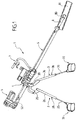
- figures 1 and 2 illustrate a device of the exoskeleton type according to an embodiment of the invention.
- This device 1 comprises two legs 2 and 3 and a connecting member 4 between the upper ends 20 and 30 of the legs, to which it is articulated.
- This triangle structure has the advantage of high rigidity for a given mass and size. It is therefore particularly robust.
- the legs 2 and 3 are connected to soles 22, 32, which comprise an actual sole 23, 33 and a stirrup 24, 34.
- the operator positions his feet on the soles 22 and 32.
- the undersides of the soles proper 23 and 33 are covered with a layer ensuring a good coefficient of adhesion between the sole and the ground. Indeed, this adhesion contributes to the balance of the operator and the device.
- the figures 6 to 8 show that the connecting member 4 is arranged to be positioned under the operator's pelvis, when the latter holds the device by the handles 6 and 7.
- connection means of harness type, between the connection member and the operator can be provided.
- This harness comprises a vest 90 worn by the operator and straps or elastic elements 91 intended to be connected to the connecting member 4.
- Each leg 2, 3 has two rods, a lower rod 25, 35 and an upper rod 26, 36, these two rods being slidably mounted relative to one another.
- the upper rods 26 and 36 have the shape of a tube whose diameter is greater than that of the lower rods 25 and 35, these lower rods being able to slide inside the upper rods 26 and 36.
- Blocking means 28, 38 for example formed by retractable blocking pins integral with one of the rods cooperating with orifices facing each other in the rod, are provided on the upper rods 26, 36 to fix the relative position of the lower rods and the upper rods. They are necessary to ensure the recovery of effort.
- the locking means are, in this embodiment, actuated manually.
- a ball joint 27, 37 connects a lower rod 25, 35 of a leg 2, 3 to a sole 22, 32.
- This ball joint is positioned to ensure the correct balance of the assembly constituted by the device and the operator, by eliminating the tilting effect of the foot and by promoting the support of the operator on a single foot.
- this ball joint can be positioned on the inside of the foot, about half of the heel and in height, for example over 100 mm.
- the device 1 comprises a tool-carrying arm 5 which here has the form of a tube. It is connected to the connecting member 4 so as to be inclined towards the ground, when the device is in use.
- the arm 5 On the side opposite to the handles 6 and 7, the arm 5 comprises a rod 8 which is mounted movable in rotation about the longitudinal axis Y of the arm.
- the rod 8 At one end 80, intended to be close to the ground, when the device is used, the rod 8 comprises a blade-type tool 81.
- the first handle 6 is fixed on the arm 5.
- this first handle is intended for gripping the device by an operator.
- this second handle 7 which is fixed to the connecting member 4 and which is therefore spaced from the first handle 6 by a non-zero distance.
- this second handle is located downstream of the connecting member 4 in the direction of inclination of the arm 5.
- the respective arrangement of the handles 6 and 7 on the arm 5 and on the connecting member 4 allows a user to return to the slotted position which he naturally adopts when handling a rake ( figure 6 ), but by correcting his posture to allow him to keep his back straight. All the applied forces are substantially in the same plane which is that of the triangle structure.
- the second handle 7 is mounted on a part 70, on which the connecting member is articulated, as will be described with reference to figures 3 and 4 .
- the arm 5 passes through this part 70 and is slidably mounted on this part 70 and therefore on the connecting member 4. Therefore, the distance between the two handles 6 and 7 can vary during the use of the device .
- actuation means 71 are controlled by means 72 for detecting the intention of the operator.
- These detection means 72 are for example in the form of a force sensor and they are provided at the level of the handle 6.
- Presence sensors 73 for example of the cell type in infrared beam mode, make it possible to ensure that the intention is voluntarily supplied by the hand of the operator.
- the actuating means 71 in particular supplied with electrical energy 74, thus make it possible to ensure the displacement in rectilinear translation of the arm 5, either in the direction of the ground, or in the direction of the operator, so as to assist the efforts of the operator, thanks to an amplification of its efforts, for example by a factor of 10.
- the force applied by the device to the tool can also be limited to prevent the risk of falling due to the forces which are not taken up by the structure and the operator, i.e. forces which do not belong to the plane defined by the triangle structure.
- This limitation is for example proportional to the weight of the operator or to the angular sweep of the rake around the Z axis.
- the rod 8 can rotate inside the arm 5, around its longitudinal axis Y (cf. figure 4 ). It is therefore movable in rotation relative to the connecting member 4. This rotation is obtained manually by the operator by acting on the first handle 6 through the transmission means 75. It could also be motorized. It makes it possible to make a turn of the rod and / or to adjust the orientation of the blade 81.
- the connecting member 4 makes it possible to ensure several degrees of freedom thanks to a double gimbal structure which is schematically illustrated in the figure 4 .
- This double gimbal comprises a first part 40, shown in the figure 4 in the form of two bent elements 400 and 401. These two elements are, in practice, a single piece.
- This universal joint comprises a second part 41 formed by two bent elements 410 and 411. They are represented in the form of two independent elements on the figure 4 but in practice constitute a unique piece.
- a first end of these elements 400 and 401 is connected to the part 70 in which the arm 5 is slidably mounted.
- Each of the bent elements 400 and 401 of the first part 40 are connected at their other end to a first end of the bent elements 410 and 411.
- the second end of these elements 410 and 411 is, for its part, connected to one end of other bent elements 28 and 38, the other end of which is fixed to one of the legs 2, 3.
- connection between the elements 400, 401 of the first part 40 and the elements 410 and 411 of the second part 41 is carried out by means of an articulation 42 allowing rotation around an axis Z.
- This axis Z passes between the two legs 2 and 3 and it is substantially vertical when the device is in use.
- these articulations 42 allow the arm 5 to rotate about the axis Z in order to achieve an angular scanning of the arm 5 and therefore of the blade 81.
- connection between the bent elements 400 and 401 of the first part 40 and the part 70 is produced by means of two articulations 43.
- joints 43 allow rotation between the elements 400 and 401 and the part 70 around an axis X which is perpendicular both to the axis Z and to the longitudinal axis Y of the arm.
- This rotational movement makes it possible to tilt the arm 5 during the use of the device to adapt this inclination to the work to be carried out.
- this rotation is obtained manually by the operator by acting on the second handle 7 which is connected to the part 70.
- Means could be provided to motorize this rotational movement, in particular in the context of working with a shovel (torque allowing the shovel to be lifted).
- connection between the bent elements 410 and 411 of the second part 41 and the bent parts 28 and 38 connected to legs 2 and 3 is carried out by means of joints 44.
- These joints 44 allow rotation along the axis X between the second part 41 and each of the legs 2 and 3, when the joints are in the rest position illustrated in the figure 4 .
- this rotation takes place around an axis X 'situated in a plane containing the axis X and perpendicular to the axis Z.
- the angle between the axes X and X' is between - 40 ° and + 40 °.
- first and second parts 40 and 41 do not have an imposed position, in the event of rotation alignment of the arm 5 with that of the legs. This remains of no consequence, insofar as the parts 40 and 41 are light and can be replaced without significant effort.
- the device according to the invention therefore comprises many degrees of freedom both in rotation and in translation. They allow the user to reproduce, with the device, the movements that he normally performs with a conventional tool such as a rake.
- FIGS. 6 to 8 respectively illustrate an intermediate working position ( figure 6 ) in which the handle 6 is at the height of the user's hip, an extreme high working position ( figure 7 ) or the tool is close to one foot of the user and an extremely low working position ( figure 8 ) where the tool is furthest from the user.
- this connecting member 4 is a vertex of the triangle-shaped structure which it forms with the legs.
- Means could be provided in order to inform the operator of his position, and thus assist him in the gesture that he must perform.
- this device provides the user with assistance with efforts, in particular horizontal efforts, and allows him to adopt a non-traumatic posture, while retaining his mobility.
- the architecture of the device according to the invention has the advantage of not resting on the user but of exploiting its weight to ensure the balance of the assembly that it forms with the device.
- This architecture promotes balance by positioning the tool holder arm in the plane formed by the ball joints and the operator's center of gravity and by lowering the point of transfer of forces (top of the triangle formed by the tool holder arm and the legs) on the device itself and in particular at the level of its connecting member.
- the arrow F1 represents the force on the tool-carrying arm, the arrow F2, the weight of the operator and the contact forces on the ground, and the arrow F3, the reaction of the ground on the device.
- This arrangement eliminates the risks of pivoting of the assembly formed by the device and the operator relative to the ground and has a significant advantage over known devices.
- the device allows him to work with his back straight and limit the movement of his weight to an oscillation between his two support points on the ground.
- the degrees of freedom of the device are sufficient for the operator to be able to carry out the gestures necessary for the performance of his work.
- the device according to the invention is very compact, which facilitates its use by the operator.
- the device according to the invention is not designed to be anthropomorphic, which considerably reduces its complexity and therefore the cost price.
- the device according to the invention does not have degrees of freedom in bending and extension of man. However, this does not hinder the movement of the operator.
- the rigidity of the structure has been favored in order to increase its robustness.
- the device according to the invention does not allow the operator to move easily during large movements (walking at high speed), it allows him to perform the gestures necessary for the performance of the required work.
- the greater displacements of the user will preferably be carried out without being equipped with the device according to the invention.
- the device which has been described previously could be modified to provide motorizations of the leg slides and which, coupled to the lower limbs of a user would facilitate walking on large displacements.
- Means for actuating the legs articulated as a function of the movements of the user could also be provided, as already described for many devices of the state of the art.
- the device is positioned in front of the operator. Another positioning of the legs is possible, for example at the rear of the operator.
- a variant consists in also fixing the first handle on the connecting member, the arm extending downstream of the connecting member and then being for example of the telescopic type.
- at least a part of the arm is fixedly mounted on the connecting member.
- the present invention is not limited to the embodiments more particularly described. On the contrary, it embraces all variants, and in particular those where the energies used are hydraulic and / or pneumatic rather than electric.
Landscapes
- Engineering & Computer Science (AREA)
- Robotics (AREA)
- Mechanical Engineering (AREA)
- Prostheses (AREA)
- Manipulator (AREA)
- Road Repair (AREA)
Description
- La présente invention concerne le domaine de la robotique et plus particulièrement les robots aptes à collaborer avec un opérateur, couramment désignés sous le terme « cobot » ou exosquelette.
- Il s'agit de systèmes mécatroniques dont les mouvements sont pilotés par ceux d'un opérateur et qui permettent d'amplifier les efforts de ce dernier.
- Ils sont par exemple utilisés pour manipuler des pièces pesantes ou de grandes dimensions ou encore pour assister le geste d'un opérateur en démultipliant ses capacités en termes d'effort, lors d'une tâche pénible et répétitive, nécessitant toutefois de conserver le savoir-faire et la flexibilité de l'homme.
- Ainsi, l'invention concerne un dispositif du type exosquelette destiné à assister les efforts horizontaux d'un opérateur valide.
- Elle concerne également un procédé d'utilisation d'un tel dispositif.
- Ce dispositif du type exosquelette comporte deux jambes agencées pour être couplées aux pieds d'un utilisateur, un organe de liaison entre les extrémités supérieures des jambes auxquelles il est articulé, ainsi qu'un bras porte-outil relié à l'organe de liaison.
- Ce dispositif peut notamment être utilisé avec des outils engendrant une forte pénibilité, notamment du fait des efforts horizontaux importants à fournir au niveau de l'outil lui-même.
- L'invention peut ainsi être utilisée avantageusement dans les secteurs du BTP (Bâtiments et Travaux Publics) et de tout autre type d'industrie nécessitant l'utilisation d'outils et donc l'assistance au travail de ces outils, comme des râteaux ou encore tout outil dont le maniement génère des efforts horizontaux importants, comme des perforateurs pour des murs verticaux.
- Le dispositif selon l'invention sera ainsi avantageusement utilisé par un opérateur qui, dans le cadre d'un chantier routier par exemple, réalise des revêtements en produits qui nécessitent un étalement, comme des enrobés.
- Cet opérateur est communément dénommé « tireur ou râteau ».
- Il réalise le revêtement grâce à un râteau et c'est lui qui fournit la force nécessaire à l'étalement du produit concerné. Cette force peut atteindre jusqu'à 70 kg.
- La réalisation du revêtement nécessite des gestes répétitifs sur de longues périodes, ces gestes entrainant une torsion du tronc de l'opérateur, ainsi qu'une forte sollicitation au niveau de l'épaule et du dos.
- Ceci peut entrainer des troubles musculo-squelettiques et une fatigue importante.
- De nombreux dispositifs ont déjà été proposés, tels que des exosquelettes d'aide à l'utilisation d'outils, pour démultiplier les capacités physiques d'un utilisateur. Certains d'entre eux sont très sophistiqués, comprenant notamment des systèmes d'actionnement des membres inférieurs, associés à des capteurs de direction et des moyens de calcul.
- Ce type de dispositifs, compte tenu de leurs complexité notamment, ne sont pas adaptés à des travaux en extérieur et sur chantier (robustesse).
- On connait aussi (
FR 3 016 821 - La présente invention a donc pour objet de fournir un dispositif du type exosquelette et un procédé d'utilisation d'un tel dispositif permettant d'apporter efficacement une assistance aux efforts horizontaux d'un opérateur, tout en étant robuste et d'un coût raisonnable.
- Dans ce but, l'invention propose notamment un dispositif du type exosquelette comprenant deux jambes agencées pour être couplées aux pieds d'un utilisateur, un organe de liaison entre les extrémités supérieures des jambes auxquelles il est articulé et un bras porte-outil, relié à l'organe de liaison,
caractérisé en ce que les jambes et l'organe de liaison sont agencés pour former sensiblement un triangle dont un sommet appartient à l'organe de liaison, de telle sorte que l'ensemble des forces appliquées convergent au sommet dudit triangle. - Ces forces comprennent l'effort sur le bras porte-outil et les réactions au sol.
- Le dispositif permet de reporter ces forces directement au sol, sans passer par le corps de l'opérateur dont on exploite simplement le poids pour maintenir l'équilibre.
- Ainsi, le corps (dos, bras) de l'utilisateur fournit moins d'efforts puisque le dispositif permet l'actionnement du bras porte-outil et apporte donc une assistance mécanique à l'utilisateur, et facilite l'équilibre.
- Dans des modes de réalisation avantageux, on a par ailleurs et/ou de plus recours à l'une et/ou à l'autre des dispositions suivantes :
- au moins une partie dudit bras est montée coulissante sur ledit organe de liaison et le dispositif comprend des moyens d'actionnement dudit bras, en fonction des mouvements de l'utilisateur, pour assurer son déplacement en translation rectiligne ;
- le dispositif comporte des moyens de détection de l'intention de l'utilisateur, reliés auxdits moyens d'actionnement pour les commander, cette commande étant réalisée en fonction du niveau de l'effort détecté ainsi que de sa direction ; on réalise ainsi une amplification de l'effort de l'opérateur.
- le bras est monté, sur l'organe de liaison, mobile en rotation autour d'un axe Z passant entre les deux jambes et sensiblement vertical lorsque le dispositif est en cours d'utilisation, pour permettre un mouvement de balayage angulaire du bras;
- le bras est monté mobile en rotation sur l'organe de liaison, autour d'un axe X sensiblement perpendiculaire à l'axe longitudinal Y et à l'axe Z, pour permettre l'inclinaison de l'outil ;
- l'organe de liaison est articulé sur chacune des jambes autour d'un axe X sensiblement perpendiculaire à l'axe Z et à l'axe longitudinal Y lorsque le dispositif est au repos, pour assurer l'indépendance entre la portion du bras porte-outil et la position des jambes de l'utilisateur ;
- le bras intègre une tige qui comporte, à une extrémité destinée à être en contact avec le sol, un outil par exemple une lame dans le cas du râteau;
- la tige est montée sur le bras en rotation autour de son axe longitudinal Y, pour permettre à la tige de faire un demi-tour et/ou permettre l'ajustement de l'orientation de la lame;
- chacune des jambes comporte deux tiges montées coulissantes l'une par rapport à l'autre, pour permettre d'ajuster la hauteur de chaque jambe, de manière à faciliter le déplacement ou le franchissement d'obstacle (montée d'une marche par exemple) des moyens de blocage étant alors prévus ;
- le dispositif comporte au moins une première poignée destinée à la préhension du dispositif par un utilisateur et dans laquelle sont prévus les moyens de détection de l'intention de l'utilisateur, ainsi que les éventuels moyens d'actionnement en rotation de la tige ;
- le dispositif comporte une deuxième poignée, écartée de la première d'une distance non nulle et fixée sur l'organe de liaison.
- L'invention propose également un procédé d'utilisation d'un dispositif du type exosquelette selon l'invention, comprenant deux jambes, un organe de liaison entre les extrémités supérieures des jambes auxquelles il est articulé et un bras porte-outil relié à l'organe de liaison, les jambes et l'organe de liaison étant agencés pour former sensiblement un triangle dont un sommet appartient à l'organe de liaison, et ledit bras étant monté coulissant sur l'organe de liaison et étant prévus des moyens d'actionnement commandés par des moyens de détection de l'intention de l'utilisateur, tel qu'un capteur d'effort, procédé selon lequel on détecte si l'utilisateur a l'intention d'exercer un effort sur le bras porte-outil, grâce auxdits moyens de détection de l'intention de l'utilisateur et, lorsque la détection est positive, on commande lesdits moyens d'actionnement du bras pour assurer son déplacement en translation rectiligne, la direction du déplacement étant identique à celle détectée par les moyens de détection.
- L'invention porte aussi sur l'utilisation du dispositif tel que décrit ci-dessus en parallèle avec les jambes d'un autre exosquelette.
- L'invention sera mieux comprise à la lecture de la description qui suit de modes de réalisation donnés ci-après à titre d'exemples non limitatifs et qui sera faite au regard des dessins suivants dans lesquels:
- La
figure 1 est une vue en perspective latérale avant d'un dispositif selon un mode de réalisation de l'invention. - La
figure 2 est une vue en perspective latérale arrière du dispositif selon lafigure 1 . - La
figure 3 est une vue en perspective illustrant de manière agrandie l'organe de liaison du dispositif illustré auxfigures 1 et2 . - La
figure 4 est une vue en perspective illustrant de manière schématique l'organe de liaison de lafigure 3 . - La
figure 5 est une vue en perspective latérale d'une poignée d'un dispositif selon un mode de réalisation de l'invention. - Les
figures 6 à 8 sont des vues en perspective de face d'un dispositif selon un mode de réalisation de l'invention, illustrant son utilisation par un opérateur. - La
figure 9 est un schéma illustrant schématiquement le dispositif et les efforts en jeu. - Dans la suite de la description, on utilisera les mêmes références numériques pour désigner des éléments identiques ou similaires.
- Il est tout d'abord fait référence aux
figures 1 et2 qui illustrent un dispositif du type exosquelette selon un mode de réalisation de l'invention. - Ce dispositif 1 comporte deux jambes 2 et 3 et un organe de liaison 4 entre les extrémités supérieures 20 et 30 des jambes, auxquelles il est articulé.
- Ces figures montrent que les jambes et l'organe de liaison sont agencés pour former sensiblement un triangle dont le sommet est formé par l'organe de liaison.
- Cette structure triangle présente l'avantage d'une rigidité importante pour une masse et un encombrement donnés. Elle est donc particulièrement robuste.
- A leur extrémité inférieure 21, 31, les jambes 2 et 3 sont reliées à des semelles 22, 32, lesquelles comportent une semelle proprement dite 23, 33 et un étrier 24, 34.
- Comme l'illustre la
figure 6 , en cours d'utilisation du dispositif, l'opérateur positionne ses pieds sur les semelles 22 et 32. - De préférence, les faces inférieures des semelles proprement dites 23 et 33 sont recouvertes d'une couche assurant un bon coefficient d'adhérence entre la semelle et le sol. En effet, cette adhérence participe à l'équilibre de l'opérateur et du dispositif.
- Les
figures 6 à 8 montrent que l'organe de liaison 4 est agencé pour être positionné sous le bassin de l'opérateur, lorsque celui-ci tient le dispositif par les poignées 6 et 7. - La
figure 6 montre également qu'un moyen de liaison, de type harnais, entre l'organe de liaison et l'opérateur peut être prévu. Ce harnais comporte un gilet 90 porté par l'opérateur et des sangles ou des éléments élastiques 91 destinés à être reliés à l'organe de liaison 4. - Chaque jambe 2, 3 comporte deux tiges, une tige inférieure 25, 35 et une tige supérieure 26, 36, ces deux tiges étant montées coulissantes l'une par rapport à l'autre.
- En pratique, comme l'illustrent les
figures 1 et2 , les tiges supérieures 26 et 36 présentent la forme d'un tube dont le diamètre est supérieur à celui des tiges inférieures 25 et 35, ces tiges inférieures pouvant ainsi coulisser à l'intérieur des tiges supérieures 26 et 36. - Cette liaison glissière entre les tiges 25 et 26 d'une part et 35 et 36 d'autre part permet d'ajuster la longueur de chaque jambe 2 et 3.
- Cet ajustement permet de tenir compte de la morphologie de l'opérateur mais il a également des conséquences sur les capacités du dispositif, comme cela sera expliqué ultérieurement.
- Des moyens de blocage 28, 38 par exemple formés par des pions de blocage escamotables solidaires d'une des tiges coopérant avec des orifices en vis-à-vis dans l'autre tige, sont prévus sur les tiges supérieures 26, 36 pour fixer la position relative des tiges inférieures et des tiges supérieures. Ils sont nécessaires pour assurer la reprise d'effort.
- Les moyens de blocage sont, dans ce mode de réalisation, actionnés manuellement.
- Par ailleurs, le coulissement entre les tiges inférieures et supérieures peut être assuré manuellement ou assisté à l'aide d'une motorisation. Les efforts nécessaires à l'équilibre pourraient également être fournis par la motorisation.
- De préférence, une rotule 27, 37 relie une tige inférieure 25, 35 d'une jambe 2, 3 à une semelle 22, 32.
- Cette rotule est positionnée pour assurer le bon équilibre de l'ensemble constitué par le dispositif et l'opérateur, en supprimant l'effet de basculement du pied et en favorisant l'appui de l'opérateur sur un pied unique.
- A titre d'exemple, on peut positionner cette rotule sur l'intérieur du pied, à environ la moitié du talon et en hauteur, par exemple sur 100 mm.
- Le dispositif 1 comporte un bras porte-outil 5 qui présente ici la forme d'un tube. Il est relié à l'organe de liaison 4 de façon à être incliné vers le sol, lorsque le dispositif est en cours d'utilisation.
- Du côté opposé aux poignées 6 et 7, le bras 5 comporte une tige 8 qui est montée mobile en rotation autour de l'axe longitudinal Y du bras.
- A une extrémité 80, destinée à être à proximité du sol, lorsque le dispositif est utilisé, la tige 8 comporte un outil du type lame 81.
- A son extrémité opposée 52 du bras 5, destinée à être à proximité du corps de l'utilisateur en cours d'utilisation (
figure 6 ), la première poignée 6 est fixée sur le bras 5. - Comme l'illustrent les
figures 6 à 8 , cette première poignée est destinée à la préhension du dispositif par un opérateur. - Il en est de même pour la deuxième poignée 7 qui est fixée à l'organe de liaison 4 et qui est donc écartée de la première poignée 6 d'une distance non nulle. Dans l'exemple illustré sur les figures, cette deuxième poignée est située en aval de l'organe de liaison 4 dans le sens d'inclinaison du bras 5.
- La disposition respective des poignées 6 et 7 sur le bras 5 et sur l'organe de liaison 4 permet à un utilisateur de retrouver la position en fente qu'il adopte naturellement lorsqu'il manie un râteau (
figure 6 ), mais en corrigeant sa posture pour lui permettant de conserver le dos droit. Toutes les forces appliquées sont sensiblement dans un même plan qui est celui de la structure triangle. - La deuxième poignée 7 est montée sur une pièce 70, sur laquelle s'articule l'organe de liaison, comme cela sera décrit en référence aux
figures 3 et4 . - Le bras 5 passe à travers cette pièce 70 et est monté coulissant sur cette pièce 70 et donc sur l'organe de liaison 4. De ce fait, la distance entre les deux poignées 6 et 7 peut varier au cours de l'utilisation du dispositif.
- A l'intérieur de cette pièce 70, sont prévus des moyens 71 d'actionnement du bras (non représentés de façon détaillée).
- Ces moyens d'actionnement 71 sont commandés grâce à des moyens 72 de détection de l'intention de l'opérateur.
- Ces moyens 72 de détection se présentent par exemple sous la forme d'un capteur d'effort et ils sont prévus au niveau de la poignée 6.
- Ces moyens de détection de l'intention de l'opérateur sont reliés, de façon connue, aux moyens d'actionnement 71 pour les commander, en fonction du niveau de l'effort détecté ainsi que de sa direction. Des capteurs de présence 73, par exemple de type cellule en mode barrage infrarouge, permettent d'assurer que l'intention est volontairement fournie par la main de l'opérateur.
- Les moyens d'actionnement 71, notamment alimenté en énergie électrique 74, permettent ainsi d'assurer le déplacement en translation rectiligne du bras 5, soit en direction du sol, soit en direction de l'opérateur, de façon à assister les efforts de l'opérateur, grâce à une amplification de ses efforts, par exemple d'un facteur 10.
- De plus, l'effort appliqué par le dispositif au niveau de l'outil peut également être limité pour prévenir les risques de chute dus aux efforts qui ne sont pas repris par la structure et l'opérateur, c'est-à-dire les efforts qui n'appartiennent pas au plan défini par la structure triangle. Cette limitation est par exemple proportionnelle au poids de l'opérateur ou au balayage angulaire du râteau autour de l'axe Z.
- Par ailleurs, la tige 8 peut tourner à l'intérieur du bras 5, autour de son axe longitudinal Y (cf.
figure 4 ). Elle est donc mobile en rotation par rapport à l'organe de liaison 4. Cette rotation est obtenue manuellement par l'opérateur en agissant sur la première poignée 6 au travers du moyen de transmission 75. Elle pourrait également être motorisée. Elle permet de faire faire un demi-tour de la tige et/ou d'ajuster l'orientation de la lame 81. - Il va maintenant être fait référence aux
figures 3 et4 pour expliquer le fonctionnement de l'organe de liaison 4, ainsi que les différents mouvements du bras 5 par rapport à l'organe de liaison 4. - L'organe de liaison 4 permet d'assurer plusieurs degrés de liberté grâce à une structure en double cardan qui est schématiquement illustrée à la
figure 4 . - Ce double cardan comporte une première pièce 40, représentée sur la
figure 4 sous la forme de deux éléments coudés 400 et 401. Ces deux éléments sont, en pratique, une pièce unique. - Ce cardan comporte une deuxième pièce 41 formée de deux éléments coudés 410 et 411. Ils sont représentés sous la forme de deux éléments indépendants sur la
figure 4 mais constituent, en pratique, une pièce unique. - Une première extrémité de ces éléments 400 et 401 est reliée à la pièce 70 dans laquelle le bras 5 est monté coulissant.
- Chacun des éléments coudés 400 et 401 de la première pièce 40 sont reliés à leur autre extrémité à une première extrémité des éléments coudés 410 et 411.
- La deuxième extrémité de ces éléments 410 et 411 est, quant à elle, reliée à une extrémité d'autres éléments coudés 28 et 38 dont l'autre extrémité est fixée sur une des jambes 2, 3.
- La liaison entre les éléments 400, 401 de la première pièce 40 et les éléments 410 et 411 de la deuxième pièce 41 est réalisée au moyen d'une articulation 42 permettant une rotation autour d'un axe Z.
- Cet axe Z passe entre les deux jambes 2 et 3 et il est sensiblement vertical lorsque le dispositif est en cours d'utilisation.
- Ainsi, ces articulations 42 permettent la rotation du bras 5 autour de l'axe Z pour réaliser un balayage angulaire du bras 5 et donc de la lame 81.
- Par ailleurs, la liaison entre les éléments coudés 400 et 401 de la première pièce 40 et la pièce 70 est réalisée au moyen de deux articulations 43.
- Ces articulations 43 permettent une rotation entre les éléments 400 et 401 et la pièce 70 autour d'un axe X qui est perpendiculaire à la fois à l'axe Z et à l'axe longitudinal Y du bras.
- Ce mouvement de rotation permet d'incliner le bras 5 au cours de l'utilisation du dispositif pour adapter cette inclinaison aux travaux à réaliser.
- Dans les modes de réalisation illustrés sur les figures, cette rotation est obtenue manuellement par l'opérateur en agissant sur la deuxième poignée 7 qui est reliée à la pièce 70.
- Des moyens pourraient être prévus pour motoriser ce mouvement de rotation, notamment dans le cadre de travail à la pelle (couple permettant de soulever la pelle).
- Il convient ici de souligner que ce mouvement de rotation autour de l'axe X est indépendant du mouvement de translation du bras 5 à l'intérieur de la pièce 70.
- La liaison entre les éléments coudés 410 et 411 de la deuxième pièce 41 et les pièces coudées 28 et 38 reliées aux jambes 2 et 3 est réalisée au moyen d'articulations 44.
- Ces articulations 44 permettent une rotation selon l'axe X entre la deuxième pièce 41 et chacune des jambes 2 et 3, lorsque les articulations sont dans la position de repos illustrée à la
figure 4 . Lorsque le dispositif est en cours d'utilisation, cette rotation s'effectue autour d'un axe X' situé dans un plan contenant l'axe X et perpendiculaire à l'axe Z. L'angle entre les axes X et X' est compris entre - 40° et + 40°. - Ces articulations permettent donc une indépendance entre la position du bras 5 et la position des jambes de l'opérateur, lors de l'utilisation du dispositif.
- Il convient de noter que la première et la deuxième pièce 40 et 41 n'ont pas de position imposée, en cas d'alignement de rotation du bras 5 avec celle des jambes. Ceci reste sans conséquence, dans la mesure où les pièces 40 et 41 sont légères et peuvent se remettre en place sans effort important.
- Le dispositif selon l'invention comporte donc de nombreux degrés de liberté tant en rotation qu'en translation. Ils permettent à l'utilisateur de reproduire, avec le dispositif, les mouvements qu'il effectue normalement avec un outil classique tel qu'un râteau.
- Ceci ressort notamment des
figures 6 à 8 qui illustrent respectivement une position de travail intermédiaire (figure 6 ) dans laquelle la poignée 6 est à la hauteur de la hanche de l'utilisateur, une position de travail extrême haute (figure 7 ) où l'outil est proche d'un pied de l'utilisateur et une position de travail extrême basse (figure 8 ) où l'outil est le plus éloigné de l'utilisateur. - Par ailleurs, toutes les articulations sont situées au niveau de l'organe de liaison 4 qui est également le point de convergence des efforts sur l'outil et des réactions au sol. On rappelle que cet organe de liaison est un sommet de la structure en forme de triangle qu'il forme avec les jambes.
- Des moyens pourraient être prévus afin de renseigner l'opérateur sur sa position, et ainsi l'assister dans le geste qu'il doit réaliser.
- Par ailleurs, ce dispositif apporte à l'utilisateur une assistance aux efforts, en particulier aux efforts horizontaux, et lui permet d'adopter une posture non traumatisante, tout en conservant sa mobilité.
- Concernant l'assistance aux efforts, l'architecture du dispositif selon l'invention présente l'avantage de ne pas prendre appui sur l'utilisateur mais d'exploiter son poids pour assurer l'équilibre de l'ensemble qu'il forme avec le dispositif.
- Cette architecture favorise l'équilibre en positionnant le bras porte-outil dans le plan formé par les rotules et le centre de gravité de l'opérateur et en abaissant le point de report des efforts (sommet du triangle formé par le bras porte outil et les jambes) sur le dispositif lui-même et notamment au niveau de son organe de liaison.
- Ceci est illustré schématiquement par la
figure 9 sur laquelle on retrouve les éléments principaux du dispositif selon l'invention : l'organe de liaison 4, les jambes 2 et 3 et les semelles 22 et 32 pour les pieds de l'utilisateur. - La flèche F1 représente l'effort sur le bras porte-outil, la flèche F2, le poids de l'opérateur et les forces de frottement de contact au sol, et la flèche F3, la réaction du sol sur le dispositif.
- Cet agencement permet de supprimer les risques de pivotement de l'ensemble formé par le dispositif et l'opérateur par rapport au sol et présente un avantage important par rapport aux dispositifs connus.
- Concernant la correction de la posture de l'utilisateur, le dispositif lui permet de travailler avec le dos droit et de limiter le déplacement de son poids à une oscillation entre ses deux points d'appui sur le sol.
- Enfin, les degrés de liberté du dispositif sont suffisants pour que l'opérateur puisse réaliser les gestes nécessaires à l'accomplissement de ses travaux.
- En effet, dans le cas de ratissage ou d'étalement, il s'agit essentiellement de déplacements latéraux et de rotations autour d'un pied.
- Il convient encore de noter que le dispositif selon l'invention est très peu encombrant, ce qui facilite son utilisation par l'opérateur.
- On a pu constater que le dispositif selon l'invention n'est pas conçu pour être anthropomorphique, ce qui en réduit considérablement la complexité et donc le prix de revient.
- Dans le cadre de la description qui précède, le dispositif selon l'invention ne présente pas de degrés de liberté en flexion et extension de l'homme. Cependant cela n'entrave pas le déplacement de l'opérateur. En effet, dans le cadre de ce mode de réalisation, a été favorisée la rigidité de la structure pour en augmenter la robustesse.
- Cependant, si le dispositif selon l'invention ne permet pas à l'opérateur de se déplacer aisément lors de déplacements importants (marche à grande vitesse), il lui permet d'effectuer les gestes nécessaires à l'accomplissement des travaux requis.
- Dans le cadre de ce mode de réalisation, les déplacements plus importants de l'utilisateur seront de préférence réalisés sans qu'il soit équipé du dispositif selon l'invention.
- Cependant, le dispositif qui a été décrit précédemment pourrait être modifié pour prévoir des motorisations des glissières des jambes et qui, couplées aux membres inférieurs d'un utilisateur faciliterait la marche sur des déplacements importants. Des moyens d'actionnement des jambes articulées en fonction des mouvements de l'utilisateur pourraient également être prévus, comme cela est déjà décrit pour de nombreux dispositifs de l'état de la technique.
- Il peut également être envisagé de monter une architecture triangle en parallèle des jambes d'un exosquelette de l'état de l'art, pour rigidifier celui-ci dans le plan transverse et ainsi reprendre plus aisément les efforts horizontaux d'un porte-outil motorisé.
- Dans la description qui précède, le dispositif est positionné à l'avant de l'opérateur. Un autre positionnement des jambes est possible, par exemple à l'arrière de l'opérateur.
- En ce qui concerne les poignées, une variante consiste à fixer également la première poignée sur l'organe de liaison, le bras s'étendant en aval de l'organe de liaison et étant alors par exemple du type télescopique. Dans cette variante, au moins une partie du bras est montée fixe sur l'organe de liaison.
- Comme il va de soi et comme il résulte également de ce qui précède, la présente invention n'est pas limitée aux modes de réalisation plus particulièrement décrits. Elle en embrasse au contraire toutes les variantes et notamment celles où les énergies utilisées sont hydrauliques et/ou pneumatiques plutôt qu'électriques.
Claims (15)
- Dispositif du type exosquelette comprenant deux jambes (2, 3) agencées pour être couplées aux pieds d'un utilisateur, un organe de liaison (4) entre les extrémités supérieures des jambes auxquelles il est articulé et un bras porte-outil (5) relié à l'organe de liaison,
caractérisé en ce que les jambes et l'organe de liaison sont agencés pour former sensiblement un triangle dont un sommet appartient à l'organe de liaison, de telle sorte que l'ensemble des forces appliquées au dispositif convergent au sommet dudit triangle. - Dispositif selon la revendication 1, caractérisé en ce qu'au moins une partie du bras (5) est montée coulissante sur ledit organe de liaison (4) et en ce que le dispositif comprend des moyens d'actionnement (71) dudit bras, en fonction des mouvements de l'utilisateur, pour assurer son déplacement en translation rectiligne.
- Dispositif selon la revendication 2, caractérisé en ce qu'il comporte des moyens de détection de l'intention (72) de l'utilisateur, reliés auxdits moyens d'actionnement (71) pour les commander, cette commande étant réalisée en fonction du niveau de l'effort détecté ainsi que de sa direction.
- Dispositif selon l'une des revendications 1 à 3, caractérisé en ce que le bras (5) est monté, sur l'organe de liaison (4), mobile en rotation autour d'un axe Z sensiblement vertical lorsque le dispositif est en cours d'utilisation.
- Dispositif selon l'une des revendications 1 à 4, caractérisé en ce que le bras (5) est monté mobile en rotation sur l'organe de liaison (4) autour d'un axe X sensiblement perpendiculaire à l'axe longitudinal Y du bras et à l'axe Z.
- Dispositif selon l'une des revendications 1 à 5, caractérisé en ce que l'organe de liaison (4) est articulé sur chacune des jambes (2, 3) autour d'un axe X sensiblement perpendiculaire à l'axe Z et à l'axe longitudinal Y du bras lorsque le dispositif est au repos.
- Dispositif selon l'une des revendications 1 à 6, caractérisé en ce que le bras comporte une tige avec un outil à une extrémité destinée à être en contact avec le sol.
- Dispositif selon la revendication 7, caractérisé en ce que le bras comporte une tige qui est montée mobile en rotation par rapport au bras, autour de son axe longitudinal Y.
- Dispositif selon l'une des revendications 1 à 8, caractérisé en ce que chacune des jambes (2, 3) comporte deux tiges (25, 26 ; 35, 36) montées coulissantes l'une par rapport à l'autre, des moyens de blocage étant prévus.
- Dispositif selon l'une des revendications 1 à 9, caractérisé en ce qu'il comporte au moins une première poignée (6) destinée à la préhension du dispositif par un utilisateur et dans laquelle sont prévus les moyens de détection de l'intention de l'utilisateur.
- Dispositif selon l'une des revendications 1 à 10, caractérisé en ce qu'il comporte une deuxième poignée (7), écartée de la première (6) d'une distance non nulle et fixée sur l'organe de liaison (4) .
- Dispositif selon l'une des revendications 1 à 11, caractérisé en ce que les jambes (2, 3) sont reliées aux semelles (22) et (32) par l'intermédiaire de rotules (27, 37).
- Dispositif selon l'une des revendications 1 à 12, caractérisé en ce que les jambes (2, 3) sont motorisées.
- Procédé d'utilisation d'un dispositif (1) du type exosquelette selon la revendication 3, comprenant deux jambes (2, 3), un organe de liaison (4) entre les extrémités supérieures desdites jambes auxquelles il est articulé et un bras porte-outil (5) relié à l'organe de liaison, les jambes et l'organe de liaison étant agencés pour former sensiblement un triangle dont un sommet appartient à l'organe de liaison, et ledit bras (5) étant monté coulissant sur l'organe de liaison (4) et étant prévus des moyens d'actionnement (71) commandés par des moyens de détection de l'intention de l'utilisateur (72), tel qu'un capteur d'effort, procédé selon lequel on détecte si l'utilisateur a l'intention d'exercer un effort sur le bras porte-outil, grâce auxdits moyens de détection de l'utilisateur et, lorsque la détection est positive, on commande lesdits moyens d'actionnement du bras pour assurer son déplacement en translation rectiligne, la direction du déplacement étant identique à celle détectée par les moyens de détection.
- Utilisation du dispositif selon l'une des revendications 1 à 13 en parallèle avec les jambes d'un autre exosquelette.
Applications Claiming Priority (2)
| Application Number | Priority Date | Filing Date | Title |
|---|---|---|---|
| FR1561585A FR3044252B1 (fr) | 2015-11-30 | 2015-11-30 | Exosquelette pour assistance aux efforts horizontaux |
| PCT/FR2016/053131 WO2017093651A1 (fr) | 2015-11-30 | 2016-11-29 | Exosquelette pour assistance aux efforts horizontaux. |
Publications (2)
| Publication Number | Publication Date |
|---|---|
| EP3383592A1 EP3383592A1 (fr) | 2018-10-10 |
| EP3383592B1 true EP3383592B1 (fr) | 2020-01-29 |
Family
ID=55300594
Family Applications (1)
| Application Number | Title | Priority Date | Filing Date |
|---|---|---|---|
| EP16813093.8A Active EP3383592B1 (fr) | 2015-11-30 | 2016-11-29 | Exosquelette pour assistance aux efforts horizontaux |
Country Status (4)
| Country | Link |
|---|---|
| EP (1) | EP3383592B1 (fr) |
| JP (1) | JP2019500184A (fr) |
| FR (1) | FR3044252B1 (fr) |
| WO (1) | WO2017093651A1 (fr) |
Families Citing this family (1)
| Publication number | Priority date | Publication date | Assignee | Title |
|---|---|---|---|---|
| DE102017123574A1 (de) * | 2017-10-10 | 2019-04-11 | Exoiq Gmbh | System zur muskelkraftunterstützung |
Family Cites Families (6)
| Publication number | Priority date | Publication date | Assignee | Title |
|---|---|---|---|---|
| JP4178185B2 (ja) * | 2004-02-17 | 2008-11-12 | 国立大学法人 筑波大学 | 装着式動作補助装置、及び装着式動作補助装置における駆動源の制御方法、及びプログラム |
| JP2007130234A (ja) * | 2005-11-10 | 2007-05-31 | Matsushita Electric Ind Co Ltd | 人体動作補助装置 |
| JP2012045194A (ja) * | 2010-08-27 | 2012-03-08 | Advanced Telecommunication Research Institute International | 外骨格型ロボット |
| WO2012154580A1 (fr) * | 2011-05-06 | 2012-11-15 | Equipois Inc. | Interface de bras d'exosquelette |
| WO2013106532A1 (fr) * | 2012-01-11 | 2013-07-18 | Brown Garrett W | Exosquelette d'instrument de calibrage résistant aux charges et aux couples |
| FR3016821B1 (fr) * | 2014-01-29 | 2019-08-02 | Robotiques 3 Dimensions | Exosquelette a port frontal et procede d'utilisation d'un tel exosquelette. |
-
2015
- 2015-11-30 FR FR1561585A patent/FR3044252B1/fr not_active Expired - Fee Related
-
2016
- 2016-11-29 WO PCT/FR2016/053131 patent/WO2017093651A1/fr not_active Ceased
- 2016-11-29 JP JP2018546770A patent/JP2019500184A/ja active Pending
- 2016-11-29 EP EP16813093.8A patent/EP3383592B1/fr active Active
Non-Patent Citations (1)
| Title |
|---|
| None * |
Also Published As
| Publication number | Publication date |
|---|---|
| JP2019500184A (ja) | 2019-01-10 |
| WO2017093651A1 (fr) | 2017-06-08 |
| EP3383592A1 (fr) | 2018-10-10 |
| FR3044252A1 (fr) | 2017-06-02 |
| FR3044252B1 (fr) | 2017-12-22 |
Similar Documents
| Publication | Publication Date | Title |
|---|---|---|
| EP3125848B1 (fr) | Exosquelette comprenant une structure de pied | |
| US20210094647A1 (en) | Self-balancing foot platform devices | |
| FR3046744A1 (fr) | Exosquelette avec jambes telescopiques a l’arriere. | |
| FR2716777A1 (fr) | Membre d'interface pied-sol pour assister le travail musculaire d'un être humain. | |
| WO2001053145A1 (fr) | Vehicule pour terrain accidente | |
| WO2019234369A1 (fr) | Châssis de véhicule agricole de largeur réglable et véhicule agricole | |
| EP3383592A1 (fr) | Exosquelette pour assistance aux efforts horizontaux | |
| EP3328593B1 (fr) | Robot collaboratif sur chariot motorise assurant un soutien de l'operateur | |
| FR3063035A1 (fr) | Exosquelette ameliore pour assistance aux efforts horizontaux. | |
| FR2969949A1 (fr) | Structure roulante, pour outil a bras connecte a un bloc aspirateur, incluant un dispositif de basculement | |
| EP2959759B1 (fr) | Machine agricole munie d'un dispositif de centrage | |
| FR3126958A1 (fr) | Véhicule terrestre compact à haute mobilité | |
| EP2836413B1 (fr) | Véhicule de transport ou porte-outil articule avec conduite au sol | |
| WO1997010033A1 (fr) | Patin a roues en ligne | |
| EP3414058B1 (fr) | Robot mobile d'assistance comprenant au moins un systeme d'appui | |
| FR3026335A1 (fr) | Exosquelette avec porte outil et procede d'utilisation d'un tel exosquelette. | |
| EP3518858B1 (fr) | Robot mobile d'assistance comprenant au moins un système d'appui pivotant | |
| EP3784950B1 (fr) | Dispositif de support pour écran tactile | |
| EP2910513A1 (fr) | Engin de levage avec réglage de garde au sol | |
| EP3792144B1 (fr) | Brouette equipee avec un systeme de prehension pivotant | |
| EP3973754B1 (fr) | Charrue réversible semi-portée à chariot ou monoroue | |
| CA1227080A (fr) | Appareil a disques pour le travail du sol | |
| EP4356705A1 (fr) | Machine agricole repliable avec une partie et un composant relies cinematiquement entre eux | |
| WO2024110172A1 (fr) | Robot à une roue sphérique mobile comprenant un tronc articulé | |
| EP4412553A1 (fr) | Stabilisateur pour chariots médicaux |
Legal Events
| Date | Code | Title | Description |
|---|---|---|---|
| STAA | Information on the status of an ep patent application or granted ep patent |
Free format text: STATUS: UNKNOWN |
|
| STAA | Information on the status of an ep patent application or granted ep patent |
Free format text: STATUS: THE INTERNATIONAL PUBLICATION HAS BEEN MADE |
|
| PUAI | Public reference made under article 153(3) epc to a published international application that has entered the european phase |
Free format text: ORIGINAL CODE: 0009012 |
|
| STAA | Information on the status of an ep patent application or granted ep patent |
Free format text: STATUS: REQUEST FOR EXAMINATION WAS MADE |
|
| 17P | Request for examination filed |
Effective date: 20180525 |
|
| AK | Designated contracting states |
Kind code of ref document: A1 Designated state(s): AL AT BE BG CH CY CZ DE DK EE ES FI FR GB GR HR HU IE IS IT LI LT LU LV MC MK MT NL NO PL PT RO RS SE SI SK SM TR |
|
| AX | Request for extension of the european patent |
Extension state: BA ME |
|
| DAV | Request for validation of the european patent (deleted) | ||
| DAX | Request for extension of the european patent (deleted) | ||
| GRAP | Despatch of communication of intention to grant a patent |
Free format text: ORIGINAL CODE: EPIDOSNIGR1 |
|
| STAA | Information on the status of an ep patent application or granted ep patent |
Free format text: STATUS: GRANT OF PATENT IS INTENDED |
|
| INTG | Intention to grant announced |
Effective date: 20190812 |
|
| GRAS | Grant fee paid |
Free format text: ORIGINAL CODE: EPIDOSNIGR3 |
|
| GRAA | (expected) grant |
Free format text: ORIGINAL CODE: 0009210 |
|
| STAA | Information on the status of an ep patent application or granted ep patent |
Free format text: STATUS: THE PATENT HAS BEEN GRANTED |
|
| AK | Designated contracting states |
Kind code of ref document: B1 Designated state(s): AL AT BE BG CH CY CZ DE DK EE ES FI FR GB GR HR HU IE IS IT LI LT LU LV MC MK MT NL NO PL PT RO RS SE SI SK SM TR |
|
| REG | Reference to a national code |
Ref country code: GB Ref legal event code: FG4D Free format text: NOT ENGLISH |
|
| REG | Reference to a national code |
Ref country code: CH Ref legal event code: EP |
|
| REG | Reference to a national code |
Ref country code: AT Ref legal event code: REF Ref document number: 1228146 Country of ref document: AT Kind code of ref document: T Effective date: 20200215 |
|
| REG | Reference to a national code |
Ref country code: IE Ref legal event code: FG4D Free format text: LANGUAGE OF EP DOCUMENT: FRENCH |
|
| REG | Reference to a national code |
Ref country code: DE Ref legal event code: R096 Ref document number: 602016028888 Country of ref document: DE |
|
| REG | Reference to a national code |
Ref country code: NL Ref legal event code: MP Effective date: 20200129 |
|
| PG25 | Lapsed in a contracting state [announced via postgrant information from national office to epo] |
Ref country code: RS Free format text: LAPSE BECAUSE OF FAILURE TO SUBMIT A TRANSLATION OF THE DESCRIPTION OR TO PAY THE FEE WITHIN THE PRESCRIBED TIME-LIMIT Effective date: 20200129 Ref country code: NO Free format text: LAPSE BECAUSE OF FAILURE TO SUBMIT A TRANSLATION OF THE DESCRIPTION OR TO PAY THE FEE WITHIN THE PRESCRIBED TIME-LIMIT Effective date: 20200429 Ref country code: PT Free format text: LAPSE BECAUSE OF FAILURE TO SUBMIT A TRANSLATION OF THE DESCRIPTION OR TO PAY THE FEE WITHIN THE PRESCRIBED TIME-LIMIT Effective date: 20200621 Ref country code: FI Free format text: LAPSE BECAUSE OF FAILURE TO SUBMIT A TRANSLATION OF THE DESCRIPTION OR TO PAY THE FEE WITHIN THE PRESCRIBED TIME-LIMIT Effective date: 20200129 |
|
| REG | Reference to a national code |
Ref country code: LT Ref legal event code: MG4D |
|
| PG25 | Lapsed in a contracting state [announced via postgrant information from national office to epo] |
Ref country code: LV Free format text: LAPSE BECAUSE OF FAILURE TO SUBMIT A TRANSLATION OF THE DESCRIPTION OR TO PAY THE FEE WITHIN THE PRESCRIBED TIME-LIMIT Effective date: 20200129 Ref country code: SE Free format text: LAPSE BECAUSE OF FAILURE TO SUBMIT A TRANSLATION OF THE DESCRIPTION OR TO PAY THE FEE WITHIN THE PRESCRIBED TIME-LIMIT Effective date: 20200129 Ref country code: HR Free format text: LAPSE BECAUSE OF FAILURE TO SUBMIT A TRANSLATION OF THE DESCRIPTION OR TO PAY THE FEE WITHIN THE PRESCRIBED TIME-LIMIT Effective date: 20200129 Ref country code: IS Free format text: LAPSE BECAUSE OF FAILURE TO SUBMIT A TRANSLATION OF THE DESCRIPTION OR TO PAY THE FEE WITHIN THE PRESCRIBED TIME-LIMIT Effective date: 20200529 Ref country code: BG Free format text: LAPSE BECAUSE OF FAILURE TO SUBMIT A TRANSLATION OF THE DESCRIPTION OR TO PAY THE FEE WITHIN THE PRESCRIBED TIME-LIMIT Effective date: 20200429 Ref country code: GR Free format text: LAPSE BECAUSE OF FAILURE TO SUBMIT A TRANSLATION OF THE DESCRIPTION OR TO PAY THE FEE WITHIN THE PRESCRIBED TIME-LIMIT Effective date: 20200430 |
|
| PG25 | Lapsed in a contracting state [announced via postgrant information from national office to epo] |
Ref country code: NL Free format text: LAPSE BECAUSE OF FAILURE TO SUBMIT A TRANSLATION OF THE DESCRIPTION OR TO PAY THE FEE WITHIN THE PRESCRIBED TIME-LIMIT Effective date: 20200129 |
|
| PG25 | Lapsed in a contracting state [announced via postgrant information from national office to epo] |
Ref country code: RO Free format text: LAPSE BECAUSE OF FAILURE TO SUBMIT A TRANSLATION OF THE DESCRIPTION OR TO PAY THE FEE WITHIN THE PRESCRIBED TIME-LIMIT Effective date: 20200129 Ref country code: SK Free format text: LAPSE BECAUSE OF FAILURE TO SUBMIT A TRANSLATION OF THE DESCRIPTION OR TO PAY THE FEE WITHIN THE PRESCRIBED TIME-LIMIT Effective date: 20200129 Ref country code: ES Free format text: LAPSE BECAUSE OF FAILURE TO SUBMIT A TRANSLATION OF THE DESCRIPTION OR TO PAY THE FEE WITHIN THE PRESCRIBED TIME-LIMIT Effective date: 20200129 Ref country code: LT Free format text: LAPSE BECAUSE OF FAILURE TO SUBMIT A TRANSLATION OF THE DESCRIPTION OR TO PAY THE FEE WITHIN THE PRESCRIBED TIME-LIMIT Effective date: 20200129 Ref country code: CZ Free format text: LAPSE BECAUSE OF FAILURE TO SUBMIT A TRANSLATION OF THE DESCRIPTION OR TO PAY THE FEE WITHIN THE PRESCRIBED TIME-LIMIT Effective date: 20200129 Ref country code: DK Free format text: LAPSE BECAUSE OF FAILURE TO SUBMIT A TRANSLATION OF THE DESCRIPTION OR TO PAY THE FEE WITHIN THE PRESCRIBED TIME-LIMIT Effective date: 20200129 Ref country code: EE Free format text: LAPSE BECAUSE OF FAILURE TO SUBMIT A TRANSLATION OF THE DESCRIPTION OR TO PAY THE FEE WITHIN THE PRESCRIBED TIME-LIMIT Effective date: 20200129 Ref country code: SM Free format text: LAPSE BECAUSE OF FAILURE TO SUBMIT A TRANSLATION OF THE DESCRIPTION OR TO PAY THE FEE WITHIN THE PRESCRIBED TIME-LIMIT Effective date: 20200129 |
|
| REG | Reference to a national code |
Ref country code: DE Ref legal event code: R097 Ref document number: 602016028888 Country of ref document: DE |
|
| REG | Reference to a national code |
Ref country code: AT Ref legal event code: MK05 Ref document number: 1228146 Country of ref document: AT Kind code of ref document: T Effective date: 20200129 |
|
| PLBE | No opposition filed within time limit |
Free format text: ORIGINAL CODE: 0009261 |
|
| STAA | Information on the status of an ep patent application or granted ep patent |
Free format text: STATUS: NO OPPOSITION FILED WITHIN TIME LIMIT |
|
| 26N | No opposition filed |
Effective date: 20201030 |
|
| PG25 | Lapsed in a contracting state [announced via postgrant information from national office to epo] |
Ref country code: AT Free format text: LAPSE BECAUSE OF FAILURE TO SUBMIT A TRANSLATION OF THE DESCRIPTION OR TO PAY THE FEE WITHIN THE PRESCRIBED TIME-LIMIT Effective date: 20200129 Ref country code: IT Free format text: LAPSE BECAUSE OF FAILURE TO SUBMIT A TRANSLATION OF THE DESCRIPTION OR TO PAY THE FEE WITHIN THE PRESCRIBED TIME-LIMIT Effective date: 20200129 |
|
| PGFP | Annual fee paid to national office [announced via postgrant information from national office to epo] |
Ref country code: FR Payment date: 20201013 Year of fee payment: 5 |
|
| PG25 | Lapsed in a contracting state [announced via postgrant information from national office to epo] |
Ref country code: PL Free format text: LAPSE BECAUSE OF FAILURE TO SUBMIT A TRANSLATION OF THE DESCRIPTION OR TO PAY THE FEE WITHIN THE PRESCRIBED TIME-LIMIT Effective date: 20200129 Ref country code: SI Free format text: LAPSE BECAUSE OF FAILURE TO SUBMIT A TRANSLATION OF THE DESCRIPTION OR TO PAY THE FEE WITHIN THE PRESCRIBED TIME-LIMIT Effective date: 20200129 |
|
| REG | Reference to a national code |
Ref country code: DE Ref legal event code: R119 Ref document number: 602016028888 Country of ref document: DE |
|
| PG25 | Lapsed in a contracting state [announced via postgrant information from national office to epo] |
Ref country code: MC Free format text: LAPSE BECAUSE OF FAILURE TO SUBMIT A TRANSLATION OF THE DESCRIPTION OR TO PAY THE FEE WITHIN THE PRESCRIBED TIME-LIMIT Effective date: 20200129 |
|
| REG | Reference to a national code |
Ref country code: CH Ref legal event code: PL |
|
| GBPC | Gb: european patent ceased through non-payment of renewal fee |
Effective date: 20201129 |
|
| PG25 | Lapsed in a contracting state [announced via postgrant information from national office to epo] |
Ref country code: LU Free format text: LAPSE BECAUSE OF NON-PAYMENT OF DUE FEES Effective date: 20201129 |
|
| REG | Reference to a national code |
Ref country code: BE Ref legal event code: MM Effective date: 20201130 |
|
| PG25 | Lapsed in a contracting state [announced via postgrant information from national office to epo] |
Ref country code: CH Free format text: LAPSE BECAUSE OF NON-PAYMENT OF DUE FEES Effective date: 20201130 Ref country code: LI Free format text: LAPSE BECAUSE OF NON-PAYMENT OF DUE FEES Effective date: 20201130 |
|
| REG | Reference to a national code |
Ref country code: IE Ref legal event code: MM4A |
|
| PG25 | Lapsed in a contracting state [announced via postgrant information from national office to epo] |
Ref country code: IE Free format text: LAPSE BECAUSE OF NON-PAYMENT OF DUE FEES Effective date: 20201129 |
|
| PG25 | Lapsed in a contracting state [announced via postgrant information from national office to epo] |
Ref country code: GB Free format text: LAPSE BECAUSE OF NON-PAYMENT OF DUE FEES Effective date: 20201129 Ref country code: DE Free format text: LAPSE BECAUSE OF NON-PAYMENT OF DUE FEES Effective date: 20210601 |
|
| PG25 | Lapsed in a contracting state [announced via postgrant information from national office to epo] |
Ref country code: TR Free format text: LAPSE BECAUSE OF FAILURE TO SUBMIT A TRANSLATION OF THE DESCRIPTION OR TO PAY THE FEE WITHIN THE PRESCRIBED TIME-LIMIT Effective date: 20200129 Ref country code: MT Free format text: LAPSE BECAUSE OF FAILURE TO SUBMIT A TRANSLATION OF THE DESCRIPTION OR TO PAY THE FEE WITHIN THE PRESCRIBED TIME-LIMIT Effective date: 20200129 Ref country code: CY Free format text: LAPSE BECAUSE OF FAILURE TO SUBMIT A TRANSLATION OF THE DESCRIPTION OR TO PAY THE FEE WITHIN THE PRESCRIBED TIME-LIMIT Effective date: 20200129 |
|
| PG25 | Lapsed in a contracting state [announced via postgrant information from national office to epo] |
Ref country code: MK Free format text: LAPSE BECAUSE OF FAILURE TO SUBMIT A TRANSLATION OF THE DESCRIPTION OR TO PAY THE FEE WITHIN THE PRESCRIBED TIME-LIMIT Effective date: 20200129 Ref country code: AL Free format text: LAPSE BECAUSE OF FAILURE TO SUBMIT A TRANSLATION OF THE DESCRIPTION OR TO PAY THE FEE WITHIN THE PRESCRIBED TIME-LIMIT Effective date: 20200129 |
|
| PG25 | Lapsed in a contracting state [announced via postgrant information from national office to epo] |
Ref country code: BE Free format text: LAPSE BECAUSE OF NON-PAYMENT OF DUE FEES Effective date: 20201130 |
|
| PG25 | Lapsed in a contracting state [announced via postgrant information from national office to epo] |
Ref country code: FR Free format text: LAPSE BECAUSE OF NON-PAYMENT OF DUE FEES Effective date: 20211130 |