EP3383313B1 - Multi-cannula negative pressure irrigation system - Google Patents
Multi-cannula negative pressure irrigation system Download PDFInfo
- Publication number
- EP3383313B1 EP3383313B1 EP16813319.7A EP16813319A EP3383313B1 EP 3383313 B1 EP3383313 B1 EP 3383313B1 EP 16813319 A EP16813319 A EP 16813319A EP 3383313 B1 EP3383313 B1 EP 3383313B1
- Authority
- EP
- European Patent Office
- Prior art keywords
- needle
- negative pressure
- irrigant
- irrigation system
- suction
- Prior art date
- Legal status (The legal status is an assumption and is not a legal conclusion. Google has not performed a legal analysis and makes no representation as to the accuracy of the status listed.)
- Active
Links
Images


Classifications
-
- A—HUMAN NECESSITIES
- A61—MEDICAL OR VETERINARY SCIENCE; HYGIENE
- A61C—DENTISTRY; APPARATUS OR METHODS FOR ORAL OR DENTAL HYGIENE
- A61C17/00—Devices for cleaning, polishing, rinsing or drying teeth, teeth cavities or prostheses; Saliva removers; Dental appliances for receiving spittle
- A61C17/02—Rinsing or air-blowing devices, e.g. using fluid jets or comprising liquid medication
- A61C17/0208—Rinsing or air-blowing devices, e.g. using fluid jets or comprising liquid medication combined with means providing suction
-
- A—HUMAN NECESSITIES
- A61—MEDICAL OR VETERINARY SCIENCE; HYGIENE
- A61C—DENTISTRY; APPARATUS OR METHODS FOR ORAL OR DENTAL HYGIENE
- A61C5/00—Filling or capping teeth
- A61C5/40—Implements for surgical treatment of the roots or nerves of the teeth; Nerve needles; Methods or instruments for medication of the roots
Definitions
- Root canal treatment devices are known for example from US2008/0138761 and US4276880 .
- NPI negative pressure irrigation
- the first limiting feature is the needle, which includes 12 micro-ports within the first 1mm near the distal end ( see e.g. FIG 1 ).
- the ports frequently clog as dental pulp fragments and cut dentin debris is sucked into the ports during use.
- the EndoVac needle for example, has a size 0.32mm external diameter, is a non-tapered needle with four sets of three laser-cut, laterally positioned offset holes are immediately proximal to its closed distal end (about the first 0.70 mm). Each hole of the set is 100 ⁇ in diameter (0.1 mm, smaller than the internal diameter of the needle) and spaced 100 ⁇ apart.
- the second limiting feature is the time required by the clinician when using the system in multi-canaled teeth because the clinician must actively hold the NPI needle at the end of in a given canal as the solution is evacuated down the root canals and out into the suction system attached to the NPI needle.
- One positive aspect of PPI is that it has a multi-cannular effect, meaning that in teeth with multiple canals, they are all cleaned simultaneously with PPI irrigation.
- NPI systems are limited to a uni-cannular effect, meaning that only a single canal at a time can be actively cleaned with NPI. Because of this, prior art NPI systems actually increase the dentist's workload in multi-cannular teeth.
- PPI 40 minutes
- NPI 5 minutes
- NPI requires five minutes of constant NPI irrigation per canal, that necessity times four equals twenty continuous minutes of attention required by the dentist rather than only ten minutes of the dentist's time spent actively irrigating with PPI.
- the third limiting feature is that NPI currently requires constant attention by the clinician to repeatedly add NaOCl to the access cavity as the solution is drawn to the end of the canal and is evacuated through the NPI needles. Whether the tooth being treated needs five minutes or 20 minutes of constant attention during NPI irrigation, it is much effort expended for a very simple need, replenishment of solution.
- NPI multi-cannular negative pressure irrigation
- the NPI system includes one or more negative pressure irrigation needles each having a closed distal end and two suction inlet ports located opposite one another immediately proximal to the closed distal end.
- the ports may be triangular in shape and, because of their size, are the only ports required along the needle. Preferably, no other suction ports are proximal to these.
- the needles are placed in communication with a dental vacuum system by way of a suction manifold.
- a suction manifold On one side of the suction manifold, there is a single tube arranged for connection to the dental vacuum system.
- a needle tube On another side of the manifold, there are one or more needle tubes, each arranged for connection to a corresponding negative pressure irrigation needle.
- An irrigant inlet tube supplies irrigant from a irrigant container into a pulp chamber or a tooth.
- the irrigant inlet tube may include a tapered end designed to tightly fit into a lateral irrigant supply port previously drilled into the pulp chamber.
- the irrigant inlet tube When in use the irrigant inlet tube is placed into the pulp chamber of the tooth and, along with the negative pressure irrigation needles which are placed in a respective canal of the tooth, is sealed with a light-cure polymer at a cavo surface of an access cavity.
- the NPI needle's suction ports may be formed by cutting a slot into a square-cut tip end of a needle material; bending a remaining sidewall portion of the needle material located on opposing sides of the slot toward one another so a respective tip end of each remaining sidewall portion contacts an opposing respective tip end; joining, welding, or bonding together the two tip ends when in contact with one another to create the closed distal end.
- a preferred embodiment of a negative pressure irrigation (“NPI") system 10 includes a NPI needle or cannula 20 with two suction inlet ports 21 at its tip end 23.
- the ports 21 are preferably non-circular in shape. Unlike the prior art, the ports 21 are the only ports within the first 1 mm from the tip end 23 and, preferably, are sized in a range of greater than 0.1 mm and less than an internal diameter of the needle 20.
- the inlet ports 21 of the needle 20 are preferably made by cutting a slot 25 in the tip end 23 of a needle material such as stainless steel or its equivalent; bending the remaining opposing sidewall portions 27 until their respective ends 29 touch; and joining, welding, or bonding together the now-touching ends 29 together.
- This arrangement provides the needle 20 with a maximum size of inlet ports 21 so the port 21, as well as the needle 20, is less likely to clog with pulp remnants and cut dentin debris.
- the closed tip end 23 prevents periapical tissue fluids from being suctioned up the needles instead of the intended irrigant (e.g. NaOCl) that is coursing down each of the canals alongside the needle or needles 20 that evacuate the canals.
- the intended irrigant e.g. NaOCl
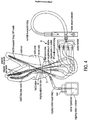
- NPI system 10 includes a tubing system 30 reduced to just a single irrigant supply tubing or line 31 connected to an irrigant container 33, a NPI needle tubing 35 connected to the needle 20 and to one side of a suction manifold 37, and a single evacuator tubing 39 connected on the other side of the suction manifold 37 and to a dental evacuation system 49.
- the irrigant supply line 31 may include an irrigant inlet tube 41 with a tapered end 43 designed to tightly fit into a lateral irrigant supply port 45 previously drilled into a pulp chamber ( see e.g. FIG. 4 ).
- the manifold 37 may have two or more NPI needle tubes 35 each arranged for connection to a corresponding NPI needle 20 for each canal in a given tooth.
- system 10 allows NPI needles 20 to be placed through the access cavity and to the end of each canal of a given tooth, along with an irrigant supply port 45 placed just into the pulp chamber of the tooth, after which a light-cure polymer 51 is syringed around these needles 20 and the irrigant supply port 45 to seal the access cavity so that all canals can be cleaned simultaneously, rendering the time needed for NPI in a four canal molar tooth, for example, to drop from 40 minutes to 10 minutes in total, without additional time required by the treating clinician.
- FIGS. 4 & 5 show two examples of system 10's application.
- the first example is in a tooth with a conventional access cavity cut into the pulp chamber.
- Each of the NPI needles 20 is inserted into the end points of the prepared canals, and an NaOCI inlet supply port 45 is placed, to feed solution into the pulp chamber.
- Each cannula is sealed with a light or chemically cured polymer 51 to create a closed system that automatically draws the NaOCI solution into the tooth through the vacuum delivered by the NPI needles 20 in each canal.
- the second example shows system 10 applied through the crown of a molar tooth that has been entered with a multiplicity of minimally invasive access holes, cut by micro-burs or laser, plus a lateral inlet supply port 45 to feed the NaOCI solution into the pulp chamber alongside the NPI needles 20 in each canal.
- each of these cannulas is sealed with a light or chemically cured polymer 49 that is easily removed after irrigation has been completed.
Description
- This invention is in the field of endodontic instruments and, more specifically, negative pressure irrigation systems for use in cleaning root canals. Root canal treatment devices are known for example from
US2008/0138761 andUS4276880 . - Scientific research and clinical experience shows negative pressure irrigation ("NPI") to be 1) one of the most effective methods of cleaning or debriding root canals, 2) very inexpensive as it uses sodium hypochlorite, the most inexpensive and most universally accepted endodontic irrigating solution and the suction system found in every dental office, and 3) the safest method of applying the highly toxic sodium hypochlorite (NaOCI, common known as bleach) solution into root canals. Despite the exceptional efficacy shown by research and clinical experience., prior art NPI systems such as the EndoVac™ system (Kerr Endodontics) include several design features that have severely limited their use in clinical practice.
- The first limiting feature is the needle, which includes 12 micro-ports within the first 1mm near the distal end (see e.g.
FIG 1 ). The ports frequently clog as dental pulp fragments and cut dentin debris is sucked into the ports during use. The EndoVac needle, for example, has a size 0.32mm external diameter, is a non-tapered needle with four sets of three laser-cut, laterally positioned offset holes are immediately proximal to its closed distal end (about the first 0.70 mm). Each hole of the set is 100 µ in diameter (0.1 mm, smaller than the internal diameter of the needle) and spaced 100 µ apart. - The second limiting feature is the time required by the clinician when using the system in multi-canaled teeth because the clinician must actively hold the NPI needle at the end of in a given canal as the solution is evacuated down the root canals and out into the suction system attached to the NPI needle. One positive aspect of PPI is that it has a multi-cannular effect, meaning that in teeth with multiple canals, they are all cleaned simultaneously with PPI irrigation.
- Current NPI systems are limited to a uni-cannular effect, meaning that only a single canal at a time can be actively cleaned with NPI. Because of this, prior art NPI systems actually increase the dentist's workload in multi-cannular teeth. Currently, using NPI instead of PPI can reduce the time needed to complete cleaning of a root canal with NaOCI from 40 minutes (PPI) to 5 minutes (NPI), however if NPI requires five minutes of constant NPI irrigation per canal, that necessity times four equals twenty continuous minutes of attention required by the dentist rather than only ten minutes of the dentist's time spent actively irrigating with PPI.
- The third limiting feature is that NPI currently requires constant attention by the clinician to repeatedly add NaOCl to the access cavity as the solution is drawn to the end of the canal and is evacuated through the NPI needles. Whether the tooth being treated needs five minutes or 20 minutes of constant attention during NPI irrigation, it is much effort expended for a very simple need, replenishment of solution.
- The preferred embodiments of a multi-cannular negative pressure irrigation ("NPI") system as disclosed here resolves all of the prior art limitations outlined above and offers the safest, least expensive, and most effective method currently known to endodontic treatment.
- In a preferred embodiment, the NPI system includes one or more negative pressure irrigation needles each having a closed distal end and two suction inlet ports located opposite one another immediately proximal to the closed distal end. The ports may be triangular in shape and, because of their size, are the only ports required along the needle. Preferably, no other suction ports are proximal to these.
- The needles are placed in communication with a dental vacuum system by way of a suction manifold. On one side of the suction manifold, there is a single tube arranged for connection to the dental vacuum system. On another side of the manifold, there are one or more needle tubes, each arranged for connection to a corresponding negative pressure irrigation needle.
- An irrigant inlet tube supplies irrigant from a irrigant container into a pulp chamber or a tooth. The irrigant inlet tube may include a tapered end designed to tightly fit into a lateral irrigant supply port previously drilled into the pulp chamber.
- When in use the irrigant inlet tube is placed into the pulp chamber of the tooth and, along with the negative pressure irrigation needles which are placed in a respective canal of the tooth, is sealed with a light-cure polymer at a cavo surface of an access cavity. This creates a negative pressure environment that draws irrigant from the irrigant container through the irrigant inlet tube and into the pulp chamber, after which the irrigant is suctioned down a canal and is evacuated from the canal by the negative pressure irrigation needle, thus maintaining a closed system vacuum.
- The NPI needle's suction ports may be formed by cutting a slot into a square-cut tip end of a needle material; bending a remaining sidewall portion of the needle material located on opposing sides of the slot toward one another so a respective tip end of each remaining sidewall portion contacts an opposing respective tip end; joining, welding, or bonding together the two tip ends when in contact with one another to create the closed distal end.
-
-
FIG. 1 is a prior art negative pressure irrigation ("NPI") needle. -
FIG. 2A is a preferred embodiment of a NPI needle prior to a first step of its fabrication process. -
FIG. 2B is the needle ofFIG. 2A after a slot is cut into the tip end. -
FIG. 2C is the needle ofFIG. 2B after opposing ends of the slot are brought together. -
FIG. 2D is the needed ofFIG. 2C after the ends are welded together, providing two inlet ports, one on each side of the needle, for suction. -
FIG. 3A is a preferred embodiment of a NaOCl inlet tube and a single suction tube connected to a manifold. -
FIG. 3B is a preferred embodiment of the manifold with two suction tubes, each corresponding to a respective NIP needle. -
FIG. 3C is a preferred embodiment of the manifold with three suction tubes. -
FIG. 3D is a preferred embodiment of the manifold with four suction tubes. -
FIG. 4 is an example of a preferred embodiment of the system used in connection with a conventional access cavity cut into the pulp chamber. -
FIG. 5 is another example of the system applied through the crown of a molar tooth that has been entered with a multiplicity of minimally invasive access holes, plus a lateral inlet port hole to feed the NaOCl solution into the pulp chamber. -
- 10
- Negative pressure irrigation system
- 20
- Needle or cannula
- 21
- Suction inlet port
- 23
- Tip or distal end
- 25
- Slot
- 27
- Remaining sidewall adjacent slot
- 29
- End of 27
- 30
- Tubing system
- 31
- Irrigant supply tubing
- 33
- Irrigant container
- 35
- Needle tubing
- 37
- Suction manifold
- 39
- Evacuator tubing
- 41
- Irrigant inlet tube or cannula
- 43
- Tapered end
- 45
- Lateral irrigant supply port
- 49
- Dental vacuum system
- 51
- Light-cure polymer
- Referring to
FIGS. 2A-D , a preferred embodiment of a negative pressure irrigation ("NPI") system 10 includes a NPI needle orcannula 20 with twosuction inlet ports 21 at itstip end 23. Theports 21 are preferably non-circular in shape. Unlike the prior art, theports 21 are the only ports within the first 1 mm from thetip end 23 and, preferably, are sized in a range of greater than 0.1 mm and less than an internal diameter of theneedle 20. - The
inlet ports 21 of theneedle 20 are preferably made by cutting aslot 25 in thetip end 23 of a needle material such as stainless steel or its equivalent; bending the remaining opposingsidewall portions 27 until their respective ends 29 touch; and joining, welding, or bonding together the now-touching ends 29 together. This arrangement provides theneedle 20 with a maximum size ofinlet ports 21 so theport 21, as well as theneedle 20, is less likely to clog with pulp remnants and cut dentin debris. Theclosed tip end 23 prevents periapical tissue fluids from being suctioned up the needles instead of the intended irrigant (e.g. NaOCl) that is coursing down each of the canals alongside the needle or needles 20 that evacuate the canals. - Referring to
FIGS. 3A-D , NPI system 10 includes atubing system 30 reduced to just a single irrigant supply tubing orline 31 connected to anirrigant container 33, aNPI needle tubing 35 connected to theneedle 20 and to one side of asuction manifold 37, and asingle evacuator tubing 39 connected on the other side of thesuction manifold 37 and to adental evacuation system 49. Theirrigant supply line 31 may include anirrigant inlet tube 41 with a tapered end 43 designed to tightly fit into a lateralirrigant supply port 45 previously drilled into a pulp chamber (see e.g.FIG. 4 ). The manifold 37 may have two or moreNPI needle tubes 35 each arranged for connection to acorresponding NPI needle 20 for each canal in a given tooth. - The preferred embodiment of system 10 allows NPI needles 20 to be placed through the access cavity and to the end of each canal of a given tooth, along with an
irrigant supply port 45 placed just into the pulp chamber of the tooth, after which a light-cure polymer 51 is syringed around theseneedles 20 and theirrigant supply port 45 to seal the access cavity so that all canals can be cleaned simultaneously, rendering the time needed for NPI in a four canal molar tooth, for example, to drop from 40 minutes to 10 minutes in total, without additional time required by the treating clinician. -
FIGS. 4 &5 show two examples of system 10's application. The first example is in a tooth with a conventional access cavity cut into the pulp chamber. Each of the NPI needles 20 is inserted into the end points of the prepared canals, and an NaOCIinlet supply port 45 is placed, to feed solution into the pulp chamber. Each cannula is sealed with a light or chemically curedpolymer 51 to create a closed system that automatically draws the NaOCI solution into the tooth through the vacuum delivered by the NPI needles 20 in each canal. - The second example shows system 10 applied through the crown of a molar tooth that has been entered with a multiplicity of minimally invasive access holes, cut by micro-burs or laser, plus a lateral
inlet supply port 45 to feed the NaOCI solution into the pulp chamber alongside the NPI needles 20 in each canal. As in the first example, each of these cannulas is sealed with a light or chemically curedpolymer 49 that is easily removed after irrigation has been completed.
Claims (6)
- An endodontic irrigation system (10) comprising:a negative pressure irrigation needle (20) including a closed distal end (23) and two suction inlet ports (21) located opposite one another immediately proximal to the closed distal end; anda suction manifold (37) including a tube (39) on one side arranged for connection to a dental vacuum system and a tube (35) on another side arranged for connection to the negative pressure irrigation needle; andan irrigant inlet tube (41).
- An endodontic irrigation system according to claim 1 further comprising more than one negative pressure irrigation needle connected to the suction manifold.
- An endodontic irrigation system according to claim 1 further comprising a lateral irrigant supply port (45), the irrigant inlet tube including a tapered end (43) designed to tightly fit into the lateral irrigant supply port (45).
- An endodontic irrigation system according to claim 1 characterised in that the negative pressure irrigation needle inlet ports are triangular in shape.
- An endodontic irrigation system according to claim 1 further comprising the two suction inlet ports being formed by:cutting a slot (25) into a square-cut tip end of a needle material;bending a remaining sidewall portion (27) of the needle material located on opposing sides of the slot toward one another so a respective tip end (29) of each remaining sidewall portion contacts an opposing respective tip end; andjoining together the two tip ends when in contact with one another to create the closed distal end.
- An endodontic irrigation system according to claim 1 wherein no other suction inlet port is proximal to the two suction inlet ports.
Applications Claiming Priority (2)
| Application Number | Priority Date | Filing Date | Title |
|---|---|---|---|
| US201562262897P | 2015-12-03 | 2015-12-03 | |
| PCT/US2016/064978 WO2017096382A1 (en) | 2015-12-03 | 2016-12-05 | Multi-cannula negative pressure irrigation system |
Publications (2)
| Publication Number | Publication Date |
|---|---|
| EP3383313A1 EP3383313A1 (en) | 2018-10-10 |
| EP3383313B1 true EP3383313B1 (en) | 2019-09-25 |
Family
ID=57570645
Family Applications (1)
| Application Number | Title | Priority Date | Filing Date |
|---|---|---|---|
| EP16813319.7A Active EP3383313B1 (en) | 2015-12-03 | 2016-12-05 | Multi-cannula negative pressure irrigation system |
Country Status (7)
| Country | Link |
|---|---|
| US (2) | US10779920B2 (en) |
| EP (1) | EP3383313B1 (en) |
| JP (1) | JP2019509071A (en) |
| BR (1) | BR112018011183A2 (en) |
| CA (1) | CA3005357A1 (en) |
| SG (1) | SG11201804120TA (en) |
| WO (1) | WO2017096382A1 (en) |
Families Citing this family (13)
| Publication number | Priority date | Publication date | Assignee | Title |
|---|---|---|---|---|
| WO2007124038A2 (en) | 2006-04-20 | 2007-11-01 | Dentatek Corporation | Apparatus and methods for treating root canals of teeth |
| US7980854B2 (en) | 2006-08-24 | 2011-07-19 | Medical Dental Advanced Technologies Group, L.L.C. | Dental and medical treatments and procedures |
| EP3878398B1 (en) | 2009-11-13 | 2024-03-06 | Sonendo, Inc. | Dental treatment apparatus |
| CN104470464A (en) | 2012-03-22 | 2015-03-25 | 索南多股份有限公司 | Apparatus and methods for cleanting teeth |
| US10631962B2 (en) | 2012-04-13 | 2020-04-28 | Sonendo, Inc. | Apparatus and methods for cleaning teeth and gingival pockets |
| US10363120B2 (en) | 2012-12-20 | 2019-07-30 | Sonendo, Inc. | Apparatus and methods for cleaning teeth and root canals |
| WO2014100751A1 (en) | 2012-12-20 | 2014-06-26 | Sonendo, Inc. | Apparatus and methods for cleaning teeth and root canals |
| WO2014210220A2 (en) | 2013-06-26 | 2014-12-31 | Sonendo, Inc. | Apparatus and methods for filling teeth and root canals |
| US10779920B2 (en) * | 2015-12-03 | 2020-09-22 | L. Stephen Buchanan | Multi-cannula negative pressure irrigation system |
| JP2022502099A (en) * | 2018-06-25 | 2022-01-11 | アンジェラス インダストリア デ プロデュトス オドントロジコス エスィ/アーAngelus Industria De Produtos Odontologicos S/A | Injection system in the root canal system and how to use it |
| CA3171211A1 (en) | 2020-03-10 | 2021-09-16 | L. Stephen Buchanan | Vacuum drawn irrigation followed by instant obturation of a root canal system using a single staging assembly |
| USD997355S1 (en) | 2020-10-07 | 2023-08-29 | Sonendo, Inc. | Dental treatment instrument |
| US20230363853A1 (en) * | 2022-05-10 | 2023-11-16 | Pac-Dent, Inc. | Ultrasonic negative pressure irrigation and evacuation high-performance polymer micro-capillary cannula |
Family Cites Families (36)
| Publication number | Priority date | Publication date | Assignee | Title |
|---|---|---|---|---|
| US2173637A (en) * | 1936-05-13 | 1939-09-19 | Riedener Franz | Device for the aseptic treatment of the root of a tooth |
| US2862495A (en) * | 1955-05-06 | 1958-12-02 | Baxter Laboratories Inc | Hypodermic needle |
| US3181336A (en) * | 1961-11-15 | 1965-05-04 | Schofield Hubert Percival | Method of producing the pointed end of a hypodermic needle |
| US3871099A (en) * | 1971-09-27 | 1975-03-18 | Kg Company | Method for cleaning cavities with a combined fluid delivering and aspirating instrument |
| BE821274A (en) * | 1974-10-18 | 1975-02-17 | PROCESS FOR CLEANING, DRYING AND FILLING HAIR TUBES OR OTHER CONDUITS CLOSED TO ONE OF THEIR ENDS AND END DIAMETER | |
| US4276880A (en) * | 1978-09-14 | 1981-07-07 | Oscar Malmin | Cannula and process |
| JPH0673530B2 (en) * | 1987-05-07 | 1994-09-21 | 株式会社 ニッショ− | Dental cleaning needle |
| ES2025326B3 (en) * | 1987-07-16 | 1992-03-16 | Meditec Sa | EQUIPMENT FOR THE TREATMENT OF THE ROOTS OF THE TEETH. |
| US5171146A (en) * | 1989-01-16 | 1992-12-15 | Sergio Guerci | Syringe for washing teeth root canals |
| US6079979A (en) * | 1998-01-28 | 2000-06-27 | Ultradent Products, Inc. | Endonontic irrigator tips and kits |
| WO1999042036A1 (en) * | 1998-02-20 | 1999-08-26 | General Surgical Innovations, Inc. | Bendable, reusable medical instruments with improved fatigue life |
| US6537068B2 (en) * | 1998-08-30 | 2003-03-25 | Kazunori Kusano | Dental glue, glue injector, and device for detecting injected glue |
| RU2212206C2 (en) * | 1999-03-12 | 2003-09-20 | Медитекник Инк. | Device for filling pulp cavity in devitalized tooth |
| DE20001584U1 (en) * | 2000-01-29 | 2000-03-23 | Universitaetsklinikum Freiburg | Rinsing cannula for rinsing a root canal of a tooth |
| US7270544B2 (en) * | 2001-03-28 | 2007-09-18 | Curozone Ireland Limited | Endodontic ozone therapy |
| US6997714B1 (en) * | 2003-03-13 | 2006-02-14 | Schoeffel G John | Method and apparatus for evacuation of root canal |
| US7226288B2 (en) * | 2003-03-13 | 2007-06-05 | Discus Dental Impressions, Inc. | Apparatus for evacuation of root canal |
| US6971878B2 (en) * | 2004-02-02 | 2005-12-06 | Pond Gary J | Apparatus and methods for treating tooth root canals |
| FR2871395B1 (en) * | 2004-06-11 | 2006-09-15 | David Weill | SIMPLIFIED CLEANING AND FILLING DEVICE |
| JP2006271651A (en) * | 2005-03-29 | 2006-10-12 | Matsumoto Shika Univ | Needle component for liquid injection, and production method thereof |
| ITMI20052076A1 (en) * | 2005-10-31 | 2007-05-01 | Stel S N C Dell Ing Ermete Riva & C | EQUIPMENT FOR ENDOTONIC TREATMENT BY CIRCULATION OF ENZYMATIC SOLUTIONS IN THE PULPAR CHAMBER AND IN THE ROOT CHANNELS |
| US20070244425A1 (en) * | 2006-03-29 | 2007-10-18 | Pond Gary J | Irrigation and aspiration handpiece device |
| WO2007124038A2 (en) * | 2006-04-20 | 2007-11-01 | Dentatek Corporation | Apparatus and methods for treating root canals of teeth |
| US20080014545A1 (en) * | 2006-05-31 | 2008-01-17 | Doug Schippers | Apical irrigation fluid delivery apparatus |
| US20080138761A1 (en) * | 2006-12-06 | 2008-06-12 | Pond Gary J | Apparatus and methods for treating tooth root canals |
| US20090004621A1 (en) * | 2007-06-27 | 2009-01-01 | Nancy Quan | Endodontic Irrigation System |
| US20100190133A1 (en) * | 2007-10-30 | 2010-07-29 | Martinez Daniel L | Irrigation and aspiration device |
| US9579485B2 (en) * | 2007-11-01 | 2017-02-28 | C. R. Bard, Inc. | Catheter assembly including a multi-lumen configuration |
| US8382722B2 (en) * | 2008-06-30 | 2013-02-26 | Covidien Lp | Blunt tip vial access cannula and method for manufacture |
| US9820834B2 (en) * | 2013-01-24 | 2017-11-21 | Dentsply International Inc. | Ultrasonic tip assembly |
| ES2485065B2 (en) * | 2013-02-11 | 2015-09-21 | Universidade De Santiago De Compostela | ENDODONTIC DEVICE BY ULTRASONIC CONTINUOUS IRRIGATION. |
| EP2986331B1 (en) * | 2013-06-06 | 2018-10-24 | Novartis AG | Transformer irrigation/aspiration device |
| WO2017011507A1 (en) * | 2015-07-13 | 2017-01-19 | Ormco Corporation | Apparatuses for evacuation of a root canal and methods of using same |
| US10779920B2 (en) * | 2015-12-03 | 2020-09-22 | L. Stephen Buchanan | Multi-cannula negative pressure irrigation system |
| CN205339187U (en) | 2016-01-21 | 2016-06-29 | 浙江一益医疗器械有限公司 | Needle is washed to dentistry |
| WO2017205601A1 (en) * | 2016-05-26 | 2017-11-30 | Ormco Corporation | Root canal debridement effectiveness device and method |
-
2016
- 2016-12-05 US US15/750,248 patent/US10779920B2/en active Active
- 2016-12-05 SG SG11201804120TA patent/SG11201804120TA/en unknown
- 2016-12-05 WO PCT/US2016/064978 patent/WO2017096382A1/en active Application Filing
- 2016-12-05 EP EP16813319.7A patent/EP3383313B1/en active Active
- 2016-12-05 JP JP2018528985A patent/JP2019509071A/en active Pending
- 2016-12-05 BR BR112018011183A patent/BR112018011183A2/en not_active Application Discontinuation
- 2016-12-05 CA CA3005357A patent/CA3005357A1/en not_active Abandoned
-
2020
- 2020-09-21 US US17/027,089 patent/US11717388B2/en active Active
Non-Patent Citations (1)
| Title |
|---|
| None * |
Also Published As
| Publication number | Publication date |
|---|---|
| JP2019509071A (en) | 2019-04-04 |
| WO2017096382A4 (en) | 2018-11-29 |
| US11717388B2 (en) | 2023-08-08 |
| SG11201804120TA (en) | 2018-06-28 |
| EP3383313A1 (en) | 2018-10-10 |
| CA3005357A1 (en) | 2017-06-08 |
| US10779920B2 (en) | 2020-09-22 |
| WO2017096382A1 (en) | 2017-06-08 |
| BR112018011183A2 (en) | 2019-01-22 |
| US20180338821A1 (en) | 2018-11-29 |
| US20210059799A1 (en) | 2021-03-04 |
Similar Documents
| Publication | Publication Date | Title |
|---|---|---|
| EP3383313B1 (en) | Multi-cannula negative pressure irrigation system | |
| Tomson et al. | Contemporary cleaning and shaping of the root canal system | |
| CA2570014C (en) | Apparatus for evacuation of root canal | |
| US6638064B1 (en) | Flexible endodontic syringe | |
| US6464498B2 (en) | Irrigation and aspiration handpiece | |
| US20090004621A1 (en) | Endodontic Irrigation System | |
| US6997714B1 (en) | Method and apparatus for evacuation of root canal | |
| JP4077725B2 (en) | Iririgator tip for endodontic treatment with cannula with annealed tip and associated method | |
| EP1998708B1 (en) | Dental apparatus for irrigating root canals of teeth | |
| US20030013064A1 (en) | Rinsing cannula for rinsing a root canal of a tooth | |
| CA3141333A1 (en) | Apparatus for treating teeth | |
| US20100279251A1 (en) | Flexible needle housing | |
| US20190099240A1 (en) | Rotary endodontic file in basket form | |
| CN114945342A (en) | Device for shaping and simultaneously irrigating and aspirating root canals | |
| US20230135573A1 (en) | Vacuum drawn irrigation followed by instant obturation of a root canal system using a single staging assembly | |
| US20110020763A1 (en) | Endodontic Applications of Tissue Liquefaction | |
| Bhondwe et al. | systems: Simple approach to root canal” | |
| US20220401197A1 (en) | Integrated endodontic irrigation and aspiration system | |
| CN215079962U (en) | Dental cavity and root canal suction device | |
| Kurtzman | Positive versus negative pressure irrigation | |
| Rhodes | Preparation of the root canal system |
Legal Events
| Date | Code | Title | Description |
|---|---|---|---|
| STAA | Information on the status of an ep patent application or granted ep patent |
Free format text: STATUS: UNKNOWN |
|
| STAA | Information on the status of an ep patent application or granted ep patent |
Free format text: STATUS: THE INTERNATIONAL PUBLICATION HAS BEEN MADE |
|
| PUAI | Public reference made under article 153(3) epc to a published international application that has entered the european phase |
Free format text: ORIGINAL CODE: 0009012 |
|
| STAA | Information on the status of an ep patent application or granted ep patent |
Free format text: STATUS: REQUEST FOR EXAMINATION WAS MADE |
|
| 17P | Request for examination filed |
Effective date: 20180518 |
|
| AK | Designated contracting states |
Kind code of ref document: A1 Designated state(s): AL AT BE BG CH CY CZ DE DK EE ES FI FR GB GR HR HU IE IS IT LI LT LU LV MC MK MT NL NO PL PT RO RS SE SI SK SM TR |
|
| AX | Request for extension of the european patent |
Extension state: BA ME |
|
| DAV | Request for validation of the european patent (deleted) | ||
| GRAP | Despatch of communication of intention to grant a patent |
Free format text: ORIGINAL CODE: EPIDOSNIGR1 |
|
| STAA | Information on the status of an ep patent application or granted ep patent |
Free format text: STATUS: GRANT OF PATENT IS INTENDED |
|
| INTG | Intention to grant announced |
Effective date: 20190502 |
|
| GRAS | Grant fee paid |
Free format text: ORIGINAL CODE: EPIDOSNIGR3 |
|
| GRAA | (expected) grant |
Free format text: ORIGINAL CODE: 0009210 |
|
| STAA | Information on the status of an ep patent application or granted ep patent |
Free format text: STATUS: THE PATENT HAS BEEN GRANTED |
|
| AK | Designated contracting states |
Kind code of ref document: B1 Designated state(s): AL AT BE BG CH CY CZ DE DK EE ES FI FR GB GR HR HU IE IS IT LI LT LU LV MC MK MT NL NO PL PT RO RS SE SI SK SM TR |
|
| AX | Request for extension of the european patent |
Extension state: BA ME |
|
| REG | Reference to a national code |
Ref country code: GB Ref legal event code: FG4D |
|
| REG | Reference to a national code |
Ref country code: CH Ref legal event code: EP |
|
| REG | Reference to a national code |
Ref country code: DE Ref legal event code: R096 Ref document number: 602016021415 Country of ref document: DE |
|
| REG | Reference to a national code |
Ref country code: CH Ref legal event code: NV Representative=s name: ABREMA AGENCE BREVETS ET MARQUES, GANGUILLET, CH Ref country code: AT Ref legal event code: REF Ref document number: 1183073 Country of ref document: AT Kind code of ref document: T Effective date: 20191015 |
|
| REG | Reference to a national code |
Ref country code: IE Ref legal event code: FG4D |
|
| REG | Reference to a national code |
Ref country code: NL Ref legal event code: FP |
|
| PG25 | Lapsed in a contracting state [announced via postgrant information from national office to epo] |
Ref country code: HR Free format text: LAPSE BECAUSE OF FAILURE TO SUBMIT A TRANSLATION OF THE DESCRIPTION OR TO PAY THE FEE WITHIN THE PRESCRIBED TIME-LIMIT Effective date: 20190925 Ref country code: SE Free format text: LAPSE BECAUSE OF FAILURE TO SUBMIT A TRANSLATION OF THE DESCRIPTION OR TO PAY THE FEE WITHIN THE PRESCRIBED TIME-LIMIT Effective date: 20190925 Ref country code: FI Free format text: LAPSE BECAUSE OF FAILURE TO SUBMIT A TRANSLATION OF THE DESCRIPTION OR TO PAY THE FEE WITHIN THE PRESCRIBED TIME-LIMIT Effective date: 20190925 Ref country code: NO Free format text: LAPSE BECAUSE OF FAILURE TO SUBMIT A TRANSLATION OF THE DESCRIPTION OR TO PAY THE FEE WITHIN THE PRESCRIBED TIME-LIMIT Effective date: 20191225 Ref country code: BG Free format text: LAPSE BECAUSE OF FAILURE TO SUBMIT A TRANSLATION OF THE DESCRIPTION OR TO PAY THE FEE WITHIN THE PRESCRIBED TIME-LIMIT Effective date: 20191225 Ref country code: LT Free format text: LAPSE BECAUSE OF FAILURE TO SUBMIT A TRANSLATION OF THE DESCRIPTION OR TO PAY THE FEE WITHIN THE PRESCRIBED TIME-LIMIT Effective date: 20190925 |
|
| REG | Reference to a national code |
Ref country code: LT Ref legal event code: MG4D |
|
| PG25 | Lapsed in a contracting state [announced via postgrant information from national office to epo] |
Ref country code: RS Free format text: LAPSE BECAUSE OF FAILURE TO SUBMIT A TRANSLATION OF THE DESCRIPTION OR TO PAY THE FEE WITHIN THE PRESCRIBED TIME-LIMIT Effective date: 20190925 Ref country code: LV Free format text: LAPSE BECAUSE OF FAILURE TO SUBMIT A TRANSLATION OF THE DESCRIPTION OR TO PAY THE FEE WITHIN THE PRESCRIBED TIME-LIMIT Effective date: 20190925 Ref country code: GR Free format text: LAPSE BECAUSE OF FAILURE TO SUBMIT A TRANSLATION OF THE DESCRIPTION OR TO PAY THE FEE WITHIN THE PRESCRIBED TIME-LIMIT Effective date: 20191226 |
|
| REG | Reference to a national code |
Ref country code: AT Ref legal event code: MK05 Ref document number: 1183073 Country of ref document: AT Kind code of ref document: T Effective date: 20190925 |
|
| PG25 | Lapsed in a contracting state [announced via postgrant information from national office to epo] |
Ref country code: PL Free format text: LAPSE BECAUSE OF FAILURE TO SUBMIT A TRANSLATION OF THE DESCRIPTION OR TO PAY THE FEE WITHIN THE PRESCRIBED TIME-LIMIT Effective date: 20190925 Ref country code: ES Free format text: LAPSE BECAUSE OF FAILURE TO SUBMIT A TRANSLATION OF THE DESCRIPTION OR TO PAY THE FEE WITHIN THE PRESCRIBED TIME-LIMIT Effective date: 20190925 Ref country code: AL Free format text: LAPSE BECAUSE OF FAILURE TO SUBMIT A TRANSLATION OF THE DESCRIPTION OR TO PAY THE FEE WITHIN THE PRESCRIBED TIME-LIMIT Effective date: 20190925 Ref country code: RO Free format text: LAPSE BECAUSE OF FAILURE TO SUBMIT A TRANSLATION OF THE DESCRIPTION OR TO PAY THE FEE WITHIN THE PRESCRIBED TIME-LIMIT Effective date: 20190925 Ref country code: PT Free format text: LAPSE BECAUSE OF FAILURE TO SUBMIT A TRANSLATION OF THE DESCRIPTION OR TO PAY THE FEE WITHIN THE PRESCRIBED TIME-LIMIT Effective date: 20200127 Ref country code: EE Free format text: LAPSE BECAUSE OF FAILURE TO SUBMIT A TRANSLATION OF THE DESCRIPTION OR TO PAY THE FEE WITHIN THE PRESCRIBED TIME-LIMIT Effective date: 20190925 Ref country code: AT Free format text: LAPSE BECAUSE OF FAILURE TO SUBMIT A TRANSLATION OF THE DESCRIPTION OR TO PAY THE FEE WITHIN THE PRESCRIBED TIME-LIMIT Effective date: 20190925 |
|
| PG25 | Lapsed in a contracting state [announced via postgrant information from national office to epo] |
Ref country code: SM Free format text: LAPSE BECAUSE OF FAILURE TO SUBMIT A TRANSLATION OF THE DESCRIPTION OR TO PAY THE FEE WITHIN THE PRESCRIBED TIME-LIMIT Effective date: 20190925 Ref country code: CZ Free format text: LAPSE BECAUSE OF FAILURE TO SUBMIT A TRANSLATION OF THE DESCRIPTION OR TO PAY THE FEE WITHIN THE PRESCRIBED TIME-LIMIT Effective date: 20190925 Ref country code: IS Free format text: LAPSE BECAUSE OF FAILURE TO SUBMIT A TRANSLATION OF THE DESCRIPTION OR TO PAY THE FEE WITHIN THE PRESCRIBED TIME-LIMIT Effective date: 20200224 Ref country code: SK Free format text: LAPSE BECAUSE OF FAILURE TO SUBMIT A TRANSLATION OF THE DESCRIPTION OR TO PAY THE FEE WITHIN THE PRESCRIBED TIME-LIMIT Effective date: 20190925 |
|
| REG | Reference to a national code |
Ref country code: DE Ref legal event code: R097 Ref document number: 602016021415 Country of ref document: DE |
|
| PG2D | Information on lapse in contracting state deleted |
Ref country code: IS |
|
| PG25 | Lapsed in a contracting state [announced via postgrant information from national office to epo] |
Ref country code: DK Free format text: LAPSE BECAUSE OF FAILURE TO SUBMIT A TRANSLATION OF THE DESCRIPTION OR TO PAY THE FEE WITHIN THE PRESCRIBED TIME-LIMIT Effective date: 20190925 Ref country code: IS Free format text: LAPSE BECAUSE OF FAILURE TO SUBMIT A TRANSLATION OF THE DESCRIPTION OR TO PAY THE FEE WITHIN THE PRESCRIBED TIME-LIMIT Effective date: 20200126 |
|
| PLBE | No opposition filed within time limit |
Free format text: ORIGINAL CODE: 0009261 |
|
| STAA | Information on the status of an ep patent application or granted ep patent |
Free format text: STATUS: NO OPPOSITION FILED WITHIN TIME LIMIT |
|
| REG | Reference to a national code |
Ref country code: BE Ref legal event code: MM Effective date: 20191231 |
|
| PG25 | Lapsed in a contracting state [announced via postgrant information from national office to epo] |
Ref country code: MC Free format text: LAPSE BECAUSE OF FAILURE TO SUBMIT A TRANSLATION OF THE DESCRIPTION OR TO PAY THE FEE WITHIN THE PRESCRIBED TIME-LIMIT Effective date: 20190925 |
|
| 26N | No opposition filed |
Effective date: 20200626 |
|
| REG | Reference to a national code |
Ref country code: CH Ref legal event code: PFUS Owner name: BUCHANAN, L. STEPHEN, US Free format text: FORMER OWNER: BUCHANAN, L. STEPHEN, US |
|
| PG25 | Lapsed in a contracting state [announced via postgrant information from national office to epo] |
Ref country code: LU Free format text: LAPSE BECAUSE OF NON-PAYMENT OF DUE FEES Effective date: 20191205 Ref country code: IE Free format text: LAPSE BECAUSE OF NON-PAYMENT OF DUE FEES Effective date: 20191205 |
|
| PG25 | Lapsed in a contracting state [announced via postgrant information from national office to epo] |
Ref country code: BE Free format text: LAPSE BECAUSE OF NON-PAYMENT OF DUE FEES Effective date: 20191231 Ref country code: SI Free format text: LAPSE BECAUSE OF FAILURE TO SUBMIT A TRANSLATION OF THE DESCRIPTION OR TO PAY THE FEE WITHIN THE PRESCRIBED TIME-LIMIT Effective date: 20190925 |
|
| PG25 | Lapsed in a contracting state [announced via postgrant information from national office to epo] |
Ref country code: CY Free format text: LAPSE BECAUSE OF FAILURE TO SUBMIT A TRANSLATION OF THE DESCRIPTION OR TO PAY THE FEE WITHIN THE PRESCRIBED TIME-LIMIT Effective date: 20190925 |
|
| PG25 | Lapsed in a contracting state [announced via postgrant information from national office to epo] |
Ref country code: MT Free format text: LAPSE BECAUSE OF FAILURE TO SUBMIT A TRANSLATION OF THE DESCRIPTION OR TO PAY THE FEE WITHIN THE PRESCRIBED TIME-LIMIT Effective date: 20190925 Ref country code: HU Free format text: LAPSE BECAUSE OF FAILURE TO SUBMIT A TRANSLATION OF THE DESCRIPTION OR TO PAY THE FEE WITHIN THE PRESCRIBED TIME-LIMIT; INVALID AB INITIO Effective date: 20161205 |
|
| PGFP | Annual fee paid to national office [announced via postgrant information from national office to epo] |
Ref country code: CH Payment date: 20211208 Year of fee payment: 6 |
|
| PGFP | Annual fee paid to national office [announced via postgrant information from national office to epo] |
Ref country code: NL Payment date: 20211208 Year of fee payment: 6 |
|
| PG25 | Lapsed in a contracting state [announced via postgrant information from national office to epo] |
Ref country code: TR Free format text: LAPSE BECAUSE OF FAILURE TO SUBMIT A TRANSLATION OF THE DESCRIPTION OR TO PAY THE FEE WITHIN THE PRESCRIBED TIME-LIMIT Effective date: 20190925 |
|
| PG25 | Lapsed in a contracting state [announced via postgrant information from national office to epo] |
Ref country code: MK Free format text: LAPSE BECAUSE OF FAILURE TO SUBMIT A TRANSLATION OF THE DESCRIPTION OR TO PAY THE FEE WITHIN THE PRESCRIBED TIME-LIMIT Effective date: 20190925 |
|
| PGFP | Annual fee paid to national office [announced via postgrant information from national office to epo] |
Ref country code: IT Payment date: 20221206 Year of fee payment: 7 Ref country code: GB Payment date: 20221124 Year of fee payment: 7 Ref country code: FR Payment date: 20221124 Year of fee payment: 7 Ref country code: DE Payment date: 20221125 Year of fee payment: 7 |
|
| P01 | Opt-out of the competence of the unified patent court (upc) registered |
Effective date: 20230525 |
|
| REG | Reference to a national code |
Ref country code: CH Ref legal event code: PL |
|
| REG | Reference to a national code |
Ref country code: NL Ref legal event code: MM Effective date: 20230101 |
|
| PG25 | Lapsed in a contracting state [announced via postgrant information from national office to epo] |
Ref country code: NL Free format text: LAPSE BECAUSE OF NON-PAYMENT OF DUE FEES Effective date: 20230101 |
|
| PG25 | Lapsed in a contracting state [announced via postgrant information from national office to epo] |
Ref country code: LI Free format text: LAPSE BECAUSE OF NON-PAYMENT OF DUE FEES Effective date: 20221231 Ref country code: CH Free format text: LAPSE BECAUSE OF NON-PAYMENT OF DUE FEES Effective date: 20221231 |