EP3383295B1 - Appareil de fixation osseuse avec mécanisme de fixation d'attaches - Google Patents
Appareil de fixation osseuse avec mécanisme de fixation d'attaches Download PDFInfo
- Publication number
- EP3383295B1 EP3383295B1 EP16871541.5A EP16871541A EP3383295B1 EP 3383295 B1 EP3383295 B1 EP 3383295B1 EP 16871541 A EP16871541 A EP 16871541A EP 3383295 B1 EP3383295 B1 EP 3383295B1
- Authority
- EP
- European Patent Office
- Prior art keywords
- lip
- opening
- attachment portion
- fastener
- spinal implant
- Prior art date
- Legal status (The legal status is an assumption and is not a legal conclusion. Google has not performed a legal analysis and makes no representation as to the accuracy of the status listed.)
- Active
Links
- 230000007246 mechanism Effects 0.000 title description 19
- 239000007943 implant Substances 0.000 claims description 61
- 210000000988 bone and bone Anatomy 0.000 description 85
- 238000000034 method Methods 0.000 description 12
- 230000014759 maintenance of location Effects 0.000 description 11
- 238000003780 insertion Methods 0.000 description 10
- 230000037431 insertion Effects 0.000 description 10
- 230000005489 elastic deformation Effects 0.000 description 6
- 239000000919 ceramic Substances 0.000 description 5
- 239000002184 metal Substances 0.000 description 5
- 229910052751 metal Inorganic materials 0.000 description 5
- 229920000642 polymer Polymers 0.000 description 5
- 239000000560 biocompatible material Substances 0.000 description 4
- 239000002131 composite material Substances 0.000 description 4
- 239000000463 material Substances 0.000 description 4
- 238000001356 surgical procedure Methods 0.000 description 4
- 230000004075 alteration Effects 0.000 description 2
- 238000005452 bending Methods 0.000 description 2
- 230000004927 fusion Effects 0.000 description 2
- 238000002513 implantation Methods 0.000 description 2
- 238000012986 modification Methods 0.000 description 2
- 230000004048 modification Effects 0.000 description 2
- 238000012800 visualization Methods 0.000 description 2
- 230000000712 assembly Effects 0.000 description 1
- 238000000429 assembly Methods 0.000 description 1
- 208000029028 brain injury Diseases 0.000 description 1
- 230000007850 degeneration Effects 0.000 description 1
- 230000001419 dependent effect Effects 0.000 description 1
- 208000014674 injury Diseases 0.000 description 1
- 150000002739 metals Chemical class 0.000 description 1
- 230000000926 neurological effect Effects 0.000 description 1
- 230000007170 pathology Effects 0.000 description 1
- 206010039722 scoliosis Diseases 0.000 description 1
- 230000000087 stabilizing effect Effects 0.000 description 1
- 230000003068 static effect Effects 0.000 description 1
- 230000008733 trauma Effects 0.000 description 1
Images


Classifications
-
- A—HUMAN NECESSITIES
- A61—MEDICAL OR VETERINARY SCIENCE; HYGIENE
- A61B—DIAGNOSIS; SURGERY; IDENTIFICATION
- A61B17/00—Surgical instruments, devices or methods, e.g. tourniquets
- A61B17/56—Surgical instruments or methods for treatment of bones or joints; Devices specially adapted therefor
- A61B17/58—Surgical instruments or methods for treatment of bones or joints; Devices specially adapted therefor for osteosynthesis, e.g. bone plates, screws, setting implements or the like
- A61B17/68—Internal fixation devices, including fasteners and spinal fixators, even if a part thereof projects from the skin
- A61B17/70—Spinal positioners or stabilisers ; Bone stabilisers comprising fluid filler in an implant
- A61B17/7059—Cortical plates
-
- A—HUMAN NECESSITIES
- A61—MEDICAL OR VETERINARY SCIENCE; HYGIENE
- A61B—DIAGNOSIS; SURGERY; IDENTIFICATION
- A61B17/00—Surgical instruments, devices or methods, e.g. tourniquets
- A61B17/56—Surgical instruments or methods for treatment of bones or joints; Devices specially adapted therefor
- A61B17/58—Surgical instruments or methods for treatment of bones or joints; Devices specially adapted therefor for osteosynthesis, e.g. bone plates, screws, setting implements or the like
- A61B17/68—Internal fixation devices, including fasteners and spinal fixators, even if a part thereof projects from the skin
- A61B17/80—Cortical plates, i.e. bone plates; Instruments for holding or positioning cortical plates, or for compressing bones attached to cortical plates
- A61B17/8023—Variable length plates adjustable in both directions
-
- A—HUMAN NECESSITIES
- A61—MEDICAL OR VETERINARY SCIENCE; HYGIENE
- A61B—DIAGNOSIS; SURGERY; IDENTIFICATION
- A61B17/00—Surgical instruments, devices or methods, e.g. tourniquets
- A61B17/56—Surgical instruments or methods for treatment of bones or joints; Devices specially adapted therefor
- A61B17/58—Surgical instruments or methods for treatment of bones or joints; Devices specially adapted therefor for osteosynthesis, e.g. bone plates, screws, setting implements or the like
- A61B17/68—Internal fixation devices, including fasteners and spinal fixators, even if a part thereof projects from the skin
- A61B17/80—Cortical plates, i.e. bone plates; Instruments for holding or positioning cortical plates, or for compressing bones attached to cortical plates
- A61B17/8033—Cortical plates, i.e. bone plates; Instruments for holding or positioning cortical plates, or for compressing bones attached to cortical plates having indirect contact with screw heads, or having contact with screw heads maintained with the aid of additional components, e.g. nuts, wedges or head covers
- A61B17/8042—Cortical plates, i.e. bone plates; Instruments for holding or positioning cortical plates, or for compressing bones attached to cortical plates having indirect contact with screw heads, or having contact with screw heads maintained with the aid of additional components, e.g. nuts, wedges or head covers the additional component being a cover over the screw head
Definitions
- the present invention relates generally to a medical implant for insertion in a space between a patient's vertebrae. More specifically, but not exclusively, the present invention concerns expandable vertebral body replacement devices with anti-backout mechanisms for implantation in a patient's spine between the vertebrae.
- Implants are typically made of metals, polymers, or ceramics, or combinations thereof and may take the form of, but are not limited to: plates, cages, rods, total disc replacements, or combinations thereof. These implants often have apertures to accommodate fasteners. These fasteners most often are screws, but can also take the form of nails, pins, or other forms. Successful fixation requires that the fasteners connectively contact the adjacent bone and do not become disengaged from it.
- the present invention relates a spinal implant as claimed hereafter. Preferred embodiments are set forth in the dependent claims.
- aspects of the present invention provide a bone fixation apparatus with a fastener securement mechanism for implantation in a patient's spine. More specifically, apparatuses for stabilizing one or more adjacent bones using a fixation plate with fasteners are disclosed.
- the apparatus is made of a rigid or elastically deformable body with apertures that facilitate fastener fixation to adjacent bone segments.
- a spinal implant including a body with a first end and a second end, a first attachment portion at the first end, wherein the first attachment portion includes a first opening with at least one lip, a second attachment portion at the second end, wherein the second attachment portion includes a second opening with at least one lip, and an intermediate portion connecting the first attachment portion and the second attachment portion.
- the spinal implant including a body with a first end and a second end, a first attachment portion at the first end, wherein the first attachment portion includes a first opening with at least one lip, a second attachment portion at the second end, wherein the second attachment portion includes a second opening with at least one lip, and an intermediate portion connecting the first attachment portion and the second attachment portion.
- the method may also include aligning the spinal implant over at least two vertebra and inserting a first bone fastener into a first vertebra of a patient through the first opening until the at least one lip engages a top surface of the first bone fastener.
- the method further includes inserting a second bone fastener into a second vertebra of the patient through the second opening until the at least one lip engages a top surface of the second bone fastener.
- a bone fixation device with a fastener securement mechanism. Further, methods of assembling and using the bone fixation device are discussed.
- proximal, distal, anterior, posterior, medial, lateral, superior, inferior, cephalad, and caudal are defined by their standard usage for indicating a particular part of a bone or implant according to the relative disposition of the natural bone or directional terms of reference.
- proximal means the portion of an implant nearest the insertion instrument
- distal indicates the portion of the implant farthest from the insertion instrument.
- anterior is a direction towards the front side of the implant
- posterior means a direction towards the back side of the implant
- medial means towards the midline of the implant
- lateral is a direction towards the sides or away from the midline of the implant
- superior means a direction above
- inferior means a direction below another object or structure
- cephalad means a direction toward the head
- cartiaudal means a direction toward the inferior part of the body.
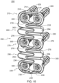
- FIGS. 1-12 depicts a bone fixation apparatus, device, implant, or plate 100.
- the terms “bone fixation system,” “bone fixation apparatus,” “bone fixation device,” “bone fixation implant,” “bone fixation plate,” “dynamic spinal fixation system,” “dynamic spinal fixation apparatus,” “dynamic spinal fixation device,” “dynamic spinal fixation implant,” and “dynamic spinal fixation plate” may be used interchangeably herein to refer to the same mechanism.
- the bone fixation device 100 is a single level system.
- the bone fixation device 100 includes a first end 102 and a second end 104.
- a first attachment portion 110 may be positioned at the first end 102 and a second attachment portion 130 is positioned at the second end 104.
- An intermediate portion 150 connects the first attachment portion 110 and the second attachment portion 130.
- the first attachment portion 110 and the second attachment portion 130 or platform sections may have a generally closed geometry, for example, a circle, ellipse, square, rectangle, or other closed geometry to facilitate placement of bone fasteners, such as bone screws, nails, staples, wires, pins, and the like.
- the first attachment portion 110 includes a first opening, aperture, or slot 112 which is oriented in a transverse direction and further includes a relief 114 or a larger aperture creating a "key hole” slot, as shown in FIGS. 1, 2 , and 5-8 .
- second attachment portion 130 includes a second opening, aperture, or slot 132 which is oriented in a transverse direction and further includes a relief 134 or larger aperture creating a "key hole” slot, as shown in FIGS.
- the reliefs 114, 134 may be centered in the first and second openings 112, 132, respectively. It is also contemplated that the reliefs 114, 134 may be positioned anywhere along the first and second openings 112, 132, respectively.
- the openings 112, 132 could also include additional reliefs allowing for additional bone fasteners to be inserted into the vertebrae before placement of the system 100 onto a patient's spine.
- the openings 112, 132 could also be oriented vertically or in any other direction. Multiple openings or tracks 112, 132 in each attachment portion 110, 130 may also be included in alternative embodiments.
- the first opening 112 includes at least one first lip, brim, retention edge, or rim 116 and at least one second lip, brim, retention edge, or rim 118.
- the lips 116, 118 may be made of various shapes and various geometries.
- the lips 116, 118 are positioned on, for example, one side of the aperture, such as, the superior or inferior side of the slot 112, and extend or overhang into the slot 112.
- the lips 116, 118 may be positioned on, for example, more than one side of the slot 112, such as, both the superior and inferior sides, and extend or overhang into the slot 112.
- the lips 116, 118 are positioned near the anterior side of the implant 100.
- the lips 116, 118 may be an integrated feature on a monolithic implant 100.
- the lips 116, 118 may be made of a suitable biocompatible material, such as, a metal, polymer, ceramic, composite, or another material that allows for some degree of elastic deformation and plastic deformation.
- the first opening 112 also includes a first interior surface 120 and a second interior surface 122, as shown in FIGS. 10 and 12 .
- the interior surfaces 120, 122 extend from under the lips 116, 118 to the posterior surface.
- the interior surfaces 120, 122 may be curved or angled in an anterior to posterior direction to correspond to the bottom surface of a fastener head (not shown).
- the curvature of the interior surfaces 120, 122 enables the fasteners to be inserted into the patient's bone at varying angles.
- the relief 114 is inset into the slot 112 and may include interior surfaces 120, 122 that extend from the anterior surface to the posterior surface of the implant 100.
- the interior surfaces 120, 122 of the relief 114 may be curved or angled in an anterior-posterior direction to correspond to the bottom surface of a fastener head (not shown).
- the second opening 132 includes at least one first lip, brim, retention edge, or rim 136 and at least one second lip, brim, retention edge, or rim 138.
- the lips 136, 138 may be made of various shapes and various geometries. In one embodiment, the lips 136, 138 are positioned on, more than one side of the slot 132, such as, both the superior and inferior sides, and extend or overhang into the slot 132.
- the lips 136, 138 are positioned near the anterior side of the implant 100.
- the lips 136, 138 may be an integrated feature on a monolithic implant 100.
- the lips 136, 138 may be made of a suitable biocompatible material, such as, a metal, polymer, ceramic, composite, or another material that allows for some degree of elastic deformation and plastic deformation.
- the second opening 132 also includes a first interior surface 140 and a second interior surface 142, as shown in FIGS. 9 and 11 .
- the interior surfaces 140, 142 extend from under the lips 136, 138 to the posterior surface.
- the interior surfaces 140, 142 may be curved or angled in an anterior to posterior direction to correspond to the inferior surface of a fastener (not shown).
- the curvature of the interior surfaces 140, 142 enables the fasteners to be inserted into the patient's bone at varying angles.
- the relief 134 is inset into the slot 132 and may include interior surfaces 140, 142 that extend from the anterior surface to the posterior surface of the implant 100.
- the interior surfaces 140, 142 of the relief 134 may be curved or angled in an anterior-posterior direction to correspond to the inferior surface of a fastener (not shown).
- the reliefs 114, 134 allow the first attachment portion 110 and second attachment portion 130 to be placed over the bone fastener heads, such as screw heads, that are already fixed to a vertebral body.
- the bone fasteners could also be pins, wires, nails, or any other method for fixing system 100 to a bone.
- the first and second openings 112, 132 are smaller than the geometry of the head of the bone fastener and the reliefs 114, 134.
- the geometry of the first and second openings 112, 132 respectively, allows the first and second attachment portions 110, 130 to be captured between the bone fastener heads and the underlying vertebra when the system 100 is slid into position between the head of the bone fasteners and the vertebra. Once the system 100 is in a desired position the surgeon may insert additional bone fasteners to secure the system 100 to the patient's spine.
- the intermediate portion 150 may include an elastic mechanism that includes a plurality of straight portions 152 and a plurality of curved portions 154.
- the straight portions 152 and the curved portions 154 of the elastic mechanism provide open areas to allow for easy spine visualization through the system 100.
- the elastic mechanism of the intermediate portion 150 may be curvilinear in shape and allow for elastic deformation in any direction when loaded. The deformation of the elastic mechanism or spring-like element is primarily in the axial direction allowing for flexion and extension.
- the system 100 is designed to be flexible in the superior/inferior direction and more rigid in lateral bending and torsion. Further, the system 100 may be shaped to match the curvature of the spine in the sagittal and transverse planes. As best seen in FIG.
- the system 100 is curved in the coronal plane to correspond to the shape of the vertebrae.
- a side view of system 100 is shown in FIG. 4 .
- the system 100 may also be curved in the sagittal plane to correspond to the shape of the spine.
- the intermediate portion 150 may be made of a non-uniform geometric shape and have a uniform or non-uniform cross-sectional geometry.
- the bone fixation device 200 includes additional attachment portions and either additional or elongated intermediate portions for engaging more than two adjacent vertebrae.
- the implant 200 may be a two level system for the spine.
- the system 200 may be shaped to match the curvature of the spine in the sagittal and coronal planes. As best seen in FIGS. 24-27 , the system 200 is curved in the coronal plane to correspond to the shape of the vertebrae.
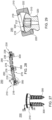
- a side view of system 200 is shown in FIGS. 19-21 and 23 .
- the system 200 may also be curved in the sagittal plane to correspond to the shape of the spine.
- the implant 200 includes a first end 202 and a second end 204.
- the implant 200 includes a first attachment portion 210 positioned at the first end 202 and a second attachment portion 230 positioned at the second end 204.
- the first and second attachment portions 210, 230 may be of the type described above with reference to FIGS. 1-12 , which will not be described again here for brevity sake.
- the implant 200 may also include an intermediate portion 250 connecting the first attachment portion 210 and the second attachment portion 230.
- the intermediate portion 250 may include, for example, a first intermediate member 260, a third attachment portion 270, and a second intermediate member 290.
- the intermediate portion 250 of the plate 200 may include multiple third attachment portions 270 and multiple intermediate members 260, 290 to allow for the plate 200 to be secured to more than two levels of a patient's spine.
- the intermediate members 260, 290 may be, for example, elastic mechanisms.
- the first intermediate member 260 and second intermediate member 290 are of the type described above with reference to intermediate member 150.
- the first intermediate member 260 and the second intermediate member 290 may each include a single elastic component including a plurality of straight portions 262, 292 and a plurality of curved portions 264, 294.
- the straight portions 262, 292 and the curved portions 264, 294 provide open areas that allow for easy visualization through the system 200 to a patient's spine.
- the first intermediate member 260 and the second intermediate member 290 may be curvilinear in shape and allow for elastic deformation in any direction when loaded. The deformation of the elastic mechanism or spring-like element is primarily in the axial direction allowing for flexion and extension.
- the system 200 is designed to be flexible in the superior/inferior direction and more rigid in lateral bending and torsion. Further, the system 200 may be shaped to match the curvature of the spine in the sagittal and coronal planes, as shown in FIGS. 19-21 and 24-27 .
- the first and second intermediate members 260, 290 may be made of a non-uniform geometric shape and have a uniform or non-uniform cross-sectional geometry.
- the third attachment portion 270 or platform sections may have a generally closed geometry, for example, a circle, ellipse, square, rectangle, or other closed geometry to facilitate placement of bone fasteners, such as bone screws, nails, staples, wires, pins, and the like.
- the third attachment portion 270 includes a first opening, aperture, or slot 272 which is oriented in a transverse direction and further includes a relief 274 or a larger aperture creating a "key hole" slot, as shown in FIG. 13 .
- the opening 272 could also include additional reliefs 274 allowing for additional bone fasteners to be inserted into the vertebrae before placement of the system 200 onto a patient's spine.
- the openings 272 could also be oriented vertically or in any other direction. Multiple openings or tracks 272 in the third attachment portion 270 may also be included in alternative embodiments.
- the first opening 272 may include at least one first lip, brim, retention edge, or rim 276 and at least one second lip, brim, retention edge, or rim 278.
- the lips 216, 218, 236, 238, 276, 278 are positioned on more than one side of the slot 212, 232, 272, such as, both the superior and inferior sides, and extend or overhang into the slot 212, 232, 272.
- the lips 216, 218 are positioned on the top, bottom and lateral sides of the slot 212.
- the lips 216, 218, 236, 238, 276, 278 may be made of various shapes and various geometries.
- the lips 116, 118, 136, 138, 216, 218, 236, 238, 276, 278 may have a wedge shape as shown in FIG. 32 , a hemispherical shape as shown in FIG. 33 , a rectangular shape as shown in FIG. 33 , or any other like shape to facilitate deformation upon insertion of a fastener and securement of the fastener once inserted into the plate 100, 200.
- the lips 216, 218, 236, 238, 276, 278 may be positioned near the anterior side of the implant 200.
- the lips 216, 218, 236, 238, 276, 278 may be an integrated feature on a monolithic implant 200.
- the lips 216, 218, 236, 238, 276, 278 may be made of a suitable biocompatible material, such as, a metal, polymer, ceramic, composite, or another material that allows for some degree of elastic deformation and plastic deformation.
- the third opening 272 may also include a first interior surface 280 and a second interior surface 282, as shown in FIGS. 13 and 23 .
- the interior surfaces 280, 282 extend from under the lips 276, 278 to the posterior surface.
- the interior surfaces 280, 282 may be curved or angled in an anterior to posterior direction to correspond to the inferior surface of a fastener 300, as shown in FIGS. 23 , 28 and 29 .
- the relief 274 is inset into the slot 272 and may include interior surfaces 280, 282 that extend from the anterior surface to the posterior surface of the implant 200.
- the interior surfaces 280, 282 of the relief 274 may be curved or angled in an anterior-posterior direction to correspond to the inferior surface of a fastener 300.
- the interior surfaces 280, 282 enable insertion of the fasteners 300 at any angle relative to the plate 200.
- the relief 274 allows the third attachment portion 270 to be placed over the bone fastener heads 310, such as screw heads, that are already fixed to a vertebral body.
- the bone fasteners 300 could also be pins, wires, nails, or any other method for fixing system 200 to a bone.
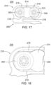
- the opening 272 is smaller than the geometry of the head 310 of the bone fastener 300 and the reliefs 274, as shown in FIGS. 14-18 .
- the geometry of the opening 272 allows the third attachment portion 270 to be captured between the bone fastener heads 310 and the underlying vertebra when the system 200 is slid into position between the head 310 of the bone fasteners 300 and the vertebra. Once the system 200 is in a desired position the surgeon may insert additional bone fasteners 300 to secure the system 200 to the patient's spine.
- a not claimed surgical method for implanting the device 100, 200 may include preparing the patient for surgery and exposing the surgical site. Next, the desired position of the plate 100, 200 may be determined and at least one first fastener 300 may be inserted into the vertebra. In one embodiment, for example, at least one first fastener 300 may be inserted into at least two adjacent bones. Once the first fasteners 300 are inserted into the bones, the reliefs 114, 134, 214, 234, 274 may be slid over the first fasteners and the plate 100, 200 rotated or translated to align with the patient's spine.
- each first fastener is positioned between one set of lips 116, 118, 136, 138, 216, 218, 236, 238, 276, 278 and one set of corresponding interior surfaces 120, 122, 140, 142, 220, 222, 240, 242, 280, 282.
- the first fastener may be slid into position in the slot 112, 132, 212, 232, 272 with the fastener head 310 anterior to the plate 100, 200.
- the fastener 300 may be tightened to secure the plate 100, 200 to the patient's vertebra by positioning the fastener head 310 between the lips 116, 118, 136, 138, 216, 218, 236, 238, 276, 278 and interior surfaces 120, 122, 140, 142, 220, 222, 240, 242, 280, 282.
- At least one second set of fasteners 300 may be inserted through the slots 112, 132, 212, 232, 272.
- the screw shaft 320 passes by the lips 116, 118, 136, 138, 216, 218, 236, 238, 276, 278.
- the head 310 of the fastener is passed by the lips 116, 118, 136, 138, 216, 218, 236, 238, 276, 278 and is positioned into the implant 100 between the lips 116, 118, 136, 138, 216, 218, 236, 238, 276, 278 and the interior surfaces 120, 122, 140, 142, 220, 222, 240, 242, 280, 282.
- the lips 116, 118, 136, 138, 216, 218, 236, 238, 276, 278 extend over the edge of the fasteners 300 to secure the fasteners 300 into the first attachment portion 110, 210, second attachment portion 130, 230, and third attachment portion 270 under normal and extreme physiologic conditions.
- the lips 116, 118, 136, 138, 216, 218, 236, 238, 276, 278 may have a geometry, specific size and shape, to enable the fasteners 300 to pass during insertion and then prevent the fasteners 300 from backing out past the lips 116, 118, 136, 138, 216, 218, 236, 238, 276, 278 during normal and extreme physiologic conditions.
- Another not claimed surgical method for implanting the device 100, 200 may include preparing the patient for surgery and exposing the surgical site. Next, the desired position of the plate 100, 200 may be determined and at least one first fastener 300 may be inserted through the plate 100, 200 and into the vertebra. In one embodiment, for example, at least one first fastener 300 may be inserted into at least two adjacent bones. During insertion of the at least one first set of fasteners 300, the screw shaft 320 passes by the lips 116, 118, 136, 138, 216, 218, 236, 238, 276, 278.
- the head 310 of the fastener is passed by the lips 116, 118, 136, 138, 216, 218, 236, 238, 276, 278 and is positioned into the implant 100 between the lips 116, 118, 136, 138, 216, 218, 236, 238, 276, 278 and the interior surfaces 120, 122, 140, 142, 220, 222, 240, 242, 280, 282.
- the lips 116, 118, 136, 138, 216, 218, 236, 238, 276, 278 extend over the edge of the fasteners 300 to secure the fasteners 300 into the first attachment portion 110, 210, second attachment portion 130, 230, and third attachment portion 270 under normal and extreme physiologic conditions.
- the first fastener may be slid into position in the slot 112, 132, 212, 232, 272 with the fastener head 310 anterior to the plate 100, 200. If the fastener head 310 in positioned anterior to the plate 100, 200, then the fastener 300 may be tightened to secure the plate 100, 200 to the patient's vertebra by positioning the fastener head 310 between the lips 116, 118, 136, 138, 216, 218, 236, 238, 276, 278 and interior surfaces 120, 122, 140, 142, 220, 222, 240, 242, 280, 282.
- At least one second set of fasteners 300 may be inserted through the slots 112, 132, 212, 232, 272 and into the patient's bones to secure the plate 100, 200.
- the screw shaft 320 pass by the lips 116, 118, 136, 138, 216, 218, 236, 238, 276, 278.
- the head 310 of the fastener is passed by the lips 116, 118, 136, 138, 216, 218, 236, 238, 276, 278 and is positioned into the implant 100 between the lips 116, 118, 136, 138, 216, 218, 236, 238, 276, 278 and the interior surfaces 120, 122, 140, 142, 220, 222, 240, 242, 280, 282, as shown in FIGS. 14-18 and 22 .
- the lips 116, 118, 136, 138, 216, 218, 236, 238, 276, 278 extend over the edge of the fasteners 300 to secure the fasteners 300 into the first attachment portion 110, 210, second attachment portion 130, 230, and third attachment portion 270 under normal and extreme physiologic conditions.
- the lips 116, 118, 136, 138, 216, 218, 236, 238, 276, 278 may have a geometry, specific size and shape, to enable the fasteners 300 to pass during insertion and then prevent the fasteners 300 from backing out past the lips 116, 118, 136, 138, 216, 218, 236, 238, 276, 278 during normal and extreme physiologic conditions.
- the fasteners 300 may be inserted through the plate 100, 200 generally perpendicular to the plate 100, 200.
- the fasteners 300 may be inserted through the plate 100, 200 at an angle with respect to the plate 100, 200.
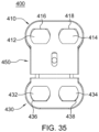
- the plate 400 contains at least two attachment portions 410, 430 or rigid platform-like sections which are used to secure the plate 400 to a patient's vertebrae.
- the attachment portions 410, 430 are generally more rigid than the rest of the plate 400 to facilitate bone fastener fixation to the bony vertebral bodies by allowing bone fasteners (not shown), such as screws, nails, staples, wires, pins, and the like, to pass through the plate 400 at the attachment portion or portions 410, 430.
- the implant 400 allows for adjustment in length of the intermediate portion 450 along the long axis of the implant 400.
- the plate 400 is a multi-component implant.
- the plate 400 includes a first attachment portion 410 including a first opening 412 and a second opening 414, a second attachment portion 430 including a first opening 432 and a second opening 434, and an intermediate portion 450.
- the first opening 412 may include a lip, brim, retention edge, or rim 416 positioned around at least a portion of the opening 412.
- the lip 416 extends into the opening 412.
- the second opening 414 may include a lip, brim, retention edge, or rim 418 positioned around at least a portion of the opening 414.
- the lip 418 extends into the opening 414.
- the first opening 432 may include a lip, brim, retention edge, or rim 436 positioned around at least a portion of the opening 432.
- the lip 436 extends into the opening 432.
- the second opening 434 may include a lip, brim, retention edge, or rim 438 positioned around at least a portion of the opening 434.
- the lip 438 extends into the opening 434.
- the lips 416, 418, 436, 438 may be an integrated feature on the implant 400.
- the lips 416, 418, 436, 438 may be made of a suitable biocompatible material, such as, a metal, polymer, ceramic, composite, or another material that allows for some degree of elastic deformation and plastic deformation.
- the implants 100, 200, 400 may be, for example, an elastic fixation plate, a rigid plate, a dynamic plate, a rod, a spinal fusion cage, or a total disc replacement.
- the plate 100, 200, 400 contains apertures to accommodate screws.
- the apertures may accommodate other forms of fasteners such as nails, pins, etc.
- the lips 116, 118, 136, 138, 216, 218, 236, 238, 276, 278, 416, 418, 436, 438, as described in greater detail above and which will not be described again here for brevity sake, may be monolithic with the apertures of the elastic fixation plates, rigid plates, dynamic plates, rods, spinal fusion cages, total disc replacements, and the like.
- a method or device that "comprises,” “has,” “includes,” or “contains” one or more steps or elements possesses those one or more steps or elements, but is not limited to possessing only those one or more steps or elements.
- a step of a method or an element of a device that "comprises,” “has,” “includes,” or “contains” one or more features possesses those one or more features, but is not limited to possessing only those one or more features.
- a device or structure that is configured in a certain way is configured in at least that way, but may also be configured in ways that are not listed.
Landscapes
- Health & Medical Sciences (AREA)
- Orthopedic Medicine & Surgery (AREA)
- Life Sciences & Earth Sciences (AREA)
- Surgery (AREA)
- Neurology (AREA)
- Heart & Thoracic Surgery (AREA)
- Engineering & Computer Science (AREA)
- Biomedical Technology (AREA)
- Nuclear Medicine, Radiotherapy & Molecular Imaging (AREA)
- Medical Informatics (AREA)
- Molecular Biology (AREA)
- Animal Behavior & Ethology (AREA)
- General Health & Medical Sciences (AREA)
- Public Health (AREA)
- Veterinary Medicine (AREA)
- Prostheses (AREA)
- Surgical Instruments (AREA)
Claims (14)
- Implant vertébral (100, 200) comprenant :un corps avec une première extrémité (102, 202) et une seconde extrémité (104, 204), un côté antérieur, une surface postérieure, un premier côté latéral et un second côté latéral ;une première partie d'attache (110, 210) au niveau de la première extrémité (102, 202), dans lequel la première partie d'attache (110, 210) comprend une première ouverture (112, 212) et dans lequel la première ouverture (112, 212) comprend :
au moins une première lèvre (116, 118, 216, 218), dans lequel la au moins une première lèvre (116, 118, 216, 218) comprend :une première partie de lèvre (116, 216) positionnée sur un premier côté de la première ouverture (112, 212) ; etune deuxième partie de lèvre (118, 218) positionnée sur un second côté de la première ouverture (112, 212) ;dans lequel la au moins une première lèvre (116, 118, 216, 218) s'étend dans la première ouverture (112, 212) à partir du côté antérieur, et dans lequel la au moins une première partie de lèvre (116, 216) de la au moins une première lèvre (116, 118, 216, 218) est espacée par rapport à la deuxième partie de lèvre (118, 218) de la au moins une première lèvre (116, 118, 216, 218) ;une première surface intérieure (120, 220) s'étendant à partir d'une partie de la première partie d'attache (110, 210) positionnée de manière adjacente à la première partie de lèvre (116, 216) de la au moins une première lèvre (116, 118, 216, 218) jusqu'à la surface postérieure du corps, et dans lequel au moins une partie de la au moins une première lèvre (116, 118, 216, 218) s'étend dans la première ouverture (112, 212) à partir d'une partie antérieure de la première surface intérieure (120, 220) ; etune seconde surface intérieure (122, 222) s'étendant à partir d'une partie de la première partie d'attache (110, 210) positionnée de manière adjacente à la deuxième partie de lèvre (118, 218) de la au moins une première lèvre (116, 118, 216, 218) jusqu'à la surface postérieure du corps, et dans lequel au moins une partie de la au moins une première lèvre (116, 118, 216, 218) s'étend dans la première ouverture (112, 212) à partir d'une partie antérieure de la seconde surface intérieure (122, 222) ; etune deuxième partie d'attache (130, 230) au niveau de la seconde extrémité (104, 204), dans lequel la deuxième partie d'attache (130, 230) comprend une deuxième ouverture (132, 232), et dans lequel la deuxième ouverture (132, 232) comprend :
au moins une deuxième lèvre (136, 138, 236, 238), dans lequel la au moins une deuxième lèvre (136, 138, 236, 238) comprend :une première partie de lèvre (136,236) positionnée sur un premier côté de la deuxième ouverture (132, 232) ; etune deuxième partie de lèvre (138, 238) positionnée sur un second côté de la deuxième ouverture (132, 232) ;dans lequel la au moins une deuxième lèvre (136, 138, 236, 238) s'étend dans la deuxième ouverture (132, 232) à partir du côté antérieur, et dans lequel la première partie de lèvre (136, 236) de la au moins une deuxième lèvre (136, 138, 236, 238) est espacée de la deuxième partie de lèvre (138, 238) de la au moins une deuxième lèvre ;une première surface intérieure (140, 240) s'étendant à partir d'une partie de la deuxième partie d'attache (130, 230) positionnée de manière adjacente à la première partie de lèvre (136, 236) de la au moins une deuxième lèvre (136, 138, 236, 238) jusqu'à la surface postérieure du corps, et dans lequel au moins une partie de la au moins une deuxième lèvre (136, 138, 236, 238) s'étend dans la deuxième ouverture (132, 232) à partir d'une partie antérieure de la première surface intérieure (140, 240) ; etune seconde surface intérieure (142, 242) s'étendant à partir d'une partie de la deuxième partie d'attache (130, 230) positionnée de manière adjacente à la deuxième partie de lèvre (138, 238) de la au moins une deuxième lèvre (136, 138, 236, 238) jusqu'à la surface postérieure du corps, et dans lequel au moins une partie de la au moins une deuxième lèvre (136, 138, 236, 238) s'étend dans la deuxième ouverture (132, 232) à partir d'une partie antérieure de la seconde surface intérieure (142, 242) ; etune partie intermédiaire (150, 250) raccordant la première partie d'attache (110, 210) et la deuxième partie d'attache (130, 230). - Implant vertébral (100, 200) selon la revendication 1, dans lequel la première ouverture (112, 212) s'étend entre le premier côté latéral et le second côté latéral, et dans lequel la deuxième ouverture (132, 232) s'étend entre le premier côté latéral et le second côté latéral.
- Implant vertébral (100, 200) selon la revendication 1, dans lequel la au moins une première lèvre (116, 118, 216, 218) comprend en outre :
une troisième partie de lèvre (116, 118, 216, 218) positionnée sur au moins un côté latéral de la première ouverture (112, 212) et raccordant la première partie de lèvre (116, 216) et la deuxième partie de lèvre (118, 218). - Implant vertébral (100, 200) selon la revendication 1, dans lequel la au moins une deuxième lèvre (136, 138, 236, 238) comprend en outre :
une troisième partie de lèvre (136, 138, 236, 238) positionnée sur au moins un côté latéral de la deuxième ouverture (132, 232) et raccordant la première partie de lèvre (136, 236) et la deuxième partie de lèvre (138, 238). - Implant vertébral (100, 200) selon la revendication 1, dans lequel la première surface intérieure (120, 140, 220, 240) est courbe, dans lequel la seconde surface intérieure (122, 142, 222, 242) est courbe.
- Implant vertébral (100, 200) selon la revendication 1, dans lequel la au moins une première lèvre (116, 118, 216, 218) de la première partie d'attache (110, 210) est monolithique avec le corps, et dans lequel la au moins une deuxième lèvre (136, 138, 236, 238) de la deuxième partie d'attache (130, 230) est monolithique avec le corps.
- Implant vertébral (100, 200) selon la revendication 1, dans lequel la première partie d'attache (110, 210) comprend en outre :un premier relief (114, 214) positionné à l'intérieur de la première ouverture (112, 212), dans lequel le premier relief (114, 214) a une hauteur supérieure à une hauteur de la première ouverture (112, 212), et dans lequel le premier relief (114, 214) est positionné dans un centre de la première ouverture (112, 212) entre le premier côté latéral et le second côté latéral ;dans lequel la deuxième partie d'attache (130, 230) comprend en outre :
un second relief (134, 234) positionné à l'intérieur de la deuxième ouverture (132, 232), dans lequel le second relief (134, 234) a une hauteur supérieure à une hauteur de la deuxième ouverture (132, 232) et dans lequel le second relief (134, 234) est positionné dans un centre de la deuxième ouverture (132, 232) entre le premier côté latéral et le second côté latéral. - Implant vertébral (100, 200) selon la revendication 1, dans lequel la partie intermédiaire (150, 250) comprend :une troisième partie d'attache (270) avec au moins une troisième ouverture (272) ;un premier élément intermédiaire (260) raccordant la première partie d'attache (210) et la troisième partie d'attache (270) ; etun second élément intermédiaire (290) raccordant la troisième partie d'attache (270) et la deuxième partie d'attache (230).
- Implant vertébral (100, 200) selon la revendication 8, dans lequel la troisième ouverture (272) comprend :
au moins une troisième lèvre (276, 278), la au moins une troisième lèvre (276, 278) étant monolithique avec le corps, dans lequel la au moins une troisième lèvre (276, 278) comprend :une première partie de lèvre (276) positionnée sur un premier côté de la troisième ouverture (272) ; etune deuxième partie de lèvre (278) positionnée sur un second côté de la troisième ouverture (272). - Implant vertébral (100, 200) selon la revendication 9, dans lequel la au moins une troisième lèvre (276, 278) comprend en outre :
une troisième partie de lèvre (276, 278) positionnée sur au moins un côté latéral de la troisième ouverture (272) et raccordant la première partie de lèvre (276) et la deuxième partie de lèvre (278). - Implant vertébral (100, 200) selon la revendication 1, comprenant en outre :au moins une première fixation (300) avec une tête (310) positionnée au-dessous de la au moins une première lèvre (116, 118, 216, 218) de la première partie d'attache (110, 210) ;au moins une seconde fixation (300) avec une tête (310) positionnée au-dessous de la au moins une deuxième lèvre (136, 138, 236, 238) de la deuxième partie d'attache (130, 230) ; etdans lequel une tige (320) d'au moins l'une parmi la au moins une première fixation (300) et la au moins une seconde fixation (300) est coudée par rapport à un axe long du corps.
- Implant vertébral (100, 200) selon la revendication 1, dans lequel la première ouverture (130, 230) est une première fente orientée dans une direction transversale, et dans lequel la deuxième ouverture (132, 232) est une seconde fente orientée dans une direction transversale.
- Implant vertébral (100, 200) selon la revendication 1, dans lequel la au moins une première lèvre (116, 118, 216, 218) a une forme curviligne et la au moins une deuxième lèvre (136, 138, 236, 238) a une forme curviligne.
- Implant vertébral (100, 200) selon la revendication 1, dans lequel la au moins une première lèvre (116, 118, 216, 218) a une forme de cale, une forme hémisphérique et une forme rectangulaire, et dans lequel la au moins une deuxième lèvre (136, 138, 236, 238) a une forme de cale, une forme hémisphérique et une forme rectangulaire.
Applications Claiming Priority (2)
| Application Number | Priority Date | Filing Date | Title |
|---|---|---|---|
| US201562261842P | 2015-12-01 | 2015-12-01 | |
| PCT/US2016/064505 WO2017096098A1 (fr) | 2015-12-01 | 2016-12-01 | Appareil de fixation osseuse avec mécanisme de fixation d'attaches et procédés d'utilisation |
Publications (4)
| Publication Number | Publication Date |
|---|---|
| EP3383295A1 EP3383295A1 (fr) | 2018-10-10 |
| EP3383295A4 EP3383295A4 (fr) | 2019-08-07 |
| EP3383295B1 true EP3383295B1 (fr) | 2023-04-12 |
| EP3383295B8 EP3383295B8 (fr) | 2023-05-24 |
Family
ID=58797864
Family Applications (1)
| Application Number | Title | Priority Date | Filing Date |
|---|---|---|---|
| EP16871541.5A Active EP3383295B8 (fr) | 2015-12-01 | 2016-12-01 | Appareil de fixation osseuse avec mécanisme de fixation d'attaches |
Country Status (3)
| Country | Link |
|---|---|
| US (1) | US10617451B2 (fr) |
| EP (1) | EP3383295B8 (fr) |
| WO (1) | WO2017096098A1 (fr) |
Family Cites Families (32)
| Publication number | Priority date | Publication date | Assignee | Title |
|---|---|---|---|---|
| EP1255498B1 (fr) * | 2000-01-27 | 2005-11-23 | SYNTHES AG Chur | Plaque pour osteosynthese |
| US6361537B1 (en) * | 2001-05-18 | 2002-03-26 | Cinci M. Anderson | Surgical plate with pawl and process for repair of a broken bone |
| US6406478B1 (en) * | 2001-05-24 | 2002-06-18 | Robert W. H. Kuo | Bone reinforcement plate for use on the spine |
| US20040019353A1 (en) | 2002-02-01 | 2004-01-29 | Freid James M. | Spinal plate system for stabilizing a portion of a spine |
| US7303564B2 (en) | 2002-02-01 | 2007-12-04 | Spinal Concepts, Inc. | Spinal plate extender system and method |
| US7175623B2 (en) | 2002-06-24 | 2007-02-13 | Lanx, Llc | Cervical plate with backout protection |
| US7001389B1 (en) * | 2002-07-05 | 2006-02-21 | Navarro Richard R | Fixed and variable locking fixation assembly |
| JP4427056B2 (ja) * | 2003-03-26 | 2010-03-03 | スイス オーソペディック ソリューションズ ソシエテ アノニム | 骨接合用固定プレート |
| US8821553B2 (en) | 2003-09-30 | 2014-09-02 | X-Spine Systems, Inc. | Spinal fusion system utilizing an implant plate having at least one integral lock |
| US7740649B2 (en) | 2004-02-26 | 2010-06-22 | Pioneer Surgical Technology, Inc. | Bone plate system and methods |
| DE102004050040A1 (de) * | 2004-10-08 | 2006-04-20 | Aesculap Ag & Co. Kg | Knochenschraube |
| US7309304B2 (en) * | 2004-12-06 | 2007-12-18 | Stewart Kenneth G | Adjustable back support device |
| US8512385B2 (en) * | 2006-07-07 | 2013-08-20 | Swiss Pro Orthopedic Sa | Bone plate with complex, adjacent holes joined by a bend relief zone |
| WO2008106101A1 (fr) * | 2007-02-26 | 2008-09-04 | Life Spine, Inc. | Plaque pour la colonne vertébrale configurée avec des orifices de vis à os |
| US20090187218A1 (en) | 2008-01-17 | 2009-07-23 | Amedica Corporation | Bone fixation plate with wire members for resisting back out of bone anchors |
| AU2009223517B2 (en) * | 2008-03-10 | 2015-02-12 | Eduardo Gonzalez-Hernandez | Bone fixation system |
| WO2009148421A1 (fr) | 2008-06-05 | 2009-12-10 | Seaspine, Inc. | Plaque de fixation spinale |
| US8211154B2 (en) | 2009-04-06 | 2012-07-03 | Lanx, Inc. | Bone plate assemblies with backout protection and visual indicator |
| US8801712B2 (en) | 2010-03-08 | 2014-08-12 | Innovasis, Inc. | Radiolucent bone plate with radiopaque marker |
| US8858603B1 (en) | 2010-06-09 | 2014-10-14 | Choice Spine, L.P. | Cervical plate with screw retention clip |
| DE102010025001B4 (de) * | 2010-06-24 | 2016-08-04 | Aap Implantate Ag | Fixationssystem mit Knochenplatte und Knochenschraube |
| JP5629505B2 (ja) * | 2010-06-25 | 2014-11-19 | 山洋電気株式会社 | 遠心ファン |
| US20120277748A1 (en) * | 2011-04-28 | 2012-11-01 | Warsaw Orthopedic, Inc. | Bone plate |
| US8668723B2 (en) | 2011-07-19 | 2014-03-11 | Neurostructures, Inc. | Anterior cervical plate |
| CA2844278C (fr) * | 2011-08-08 | 2018-11-13 | Revivo Medical, Llc | Systeme de fixation vertebral dynamique, procede d'utilisation, et parties d'attachement de systeme de fixation vertebral |
| US9351768B2 (en) | 2011-08-26 | 2016-05-31 | Life Spine, Inc. | Bone screw retention in a spinal implant |
| EP2753255B1 (fr) * | 2011-09-06 | 2016-08-10 | DePuy Synthes Products, LLC | Plaque vissée pour arthrodèse pancarpienne |
| US10751099B2 (en) * | 2011-09-12 | 2020-08-25 | Dietmar Wolter | Bone plate |
| US9107710B1 (en) | 2012-02-02 | 2015-08-18 | Alliance Partners, Llc | Bone fixation assembly |
| US20150245859A1 (en) | 2012-10-19 | 2015-09-03 | Deroyal Industries, Inc. | Cervical Plate With Retaining Clip |
| US9943341B2 (en) | 2013-07-16 | 2018-04-17 | K2M, Llc | Retention plate member for a spinal plate system |
| US10258395B2 (en) | 2014-09-25 | 2019-04-16 | Stryker European Holdings I, Llc | Bone plate locking mechanism |
-
2016
- 2016-12-01 EP EP16871541.5A patent/EP3383295B8/fr active Active
- 2016-12-01 WO PCT/US2016/064505 patent/WO2017096098A1/fr active Application Filing
-
2018
- 2018-06-01 US US15/995,876 patent/US10617451B2/en active Active
Also Published As
| Publication number | Publication date |
|---|---|
| EP3383295B8 (fr) | 2023-05-24 |
| WO2017096098A1 (fr) | 2017-06-08 |
| US20180271564A1 (en) | 2018-09-27 |
| EP3383295A1 (fr) | 2018-10-10 |
| EP3383295A4 (fr) | 2019-08-07 |
| US10617451B2 (en) | 2020-04-14 |
Similar Documents
| Publication | Publication Date | Title |
|---|---|---|
| US11826081B2 (en) | Implantable vertebral frame systems and related methods for spinal repair | |
| US7871441B2 (en) | Cervical fixation device | |
| US8728165B2 (en) | Orthopaedic implants and protheses | |
| US8747474B2 (en) | Orthopedic support locating or centering feature and method | |
| US9039772B2 (en) | Image-based patient-specific medical spinal surgery method and spinal prosthesis | |
| US9820867B2 (en) | Three column spinal fixation implants and associated surgical methods | |
| US20110319943A1 (en) | Surgical Fixation System and Related Methods | |
| JP2016527004A (ja) | 椎体間固定用の装置、システム、及び方法 | |
| US20130190874A1 (en) | Orthopedic implants with flexible screws | |
| US9480510B2 (en) | Devices, systems and methods of attaching same to the spine | |
| US9839449B2 (en) | Translational plate and compressor instrument | |
| EP3747382A1 (fr) | Dispositif de fixation vertébrale | |
| US11464553B2 (en) | Pre-contoured buttress plate for posterior wall acetabular fractures | |
| US8292923B1 (en) | Systems and methods for treating spinal stenosis | |
| EP3383295B1 (fr) | Appareil de fixation osseuse avec mécanisme de fixation d'attaches | |
| US9918750B2 (en) | Method, system, and apparatus for temporary anterior cervical plate fixation | |
| KR102343355B1 (ko) | 척추고정장치 | |
| US20240115398A1 (en) | Patient-matched modular implants and instruments | |
| US10582955B2 (en) | Methods of implanting bone plate assemblies | |
| MXPA06006559A (en) | Instrument for the insertion of an intervertebral articular prosthesis |
Legal Events
| Date | Code | Title | Description |
|---|---|---|---|
| STAA | Information on the status of an ep patent application or granted ep patent |
Free format text: STATUS: THE INTERNATIONAL PUBLICATION HAS BEEN MADE |
|
| PUAI | Public reference made under article 153(3) epc to a published international application that has entered the european phase |
Free format text: ORIGINAL CODE: 0009012 |
|
| STAA | Information on the status of an ep patent application or granted ep patent |
Free format text: STATUS: REQUEST FOR EXAMINATION WAS MADE |
|
| 17P | Request for examination filed |
Effective date: 20180627 |
|
| AK | Designated contracting states |
Kind code of ref document: A1 Designated state(s): AL AT BE BG CH CY CZ DE DK EE ES FI FR GB GR HR HU IE IS IT LI LT LU LV MC MK MT NL NO PL PT RO RS SE SI SK SM TR |
|
| AX | Request for extension of the european patent |
Extension state: BA ME |
|
| DAV | Request for validation of the european patent (deleted) | ||
| DAX | Request for extension of the european patent (deleted) | ||
| A4 | Supplementary search report drawn up and despatched |
Effective date: 20190710 |
|
| RIC1 | Information provided on ipc code assigned before grant |
Ipc: A61B 17/80 20060101ALI20190704BHEP Ipc: A61B 17/70 20060101AFI20190704BHEP |
|
| GRAP | Despatch of communication of intention to grant a patent |
Free format text: ORIGINAL CODE: EPIDOSNIGR1 |
|
| STAA | Information on the status of an ep patent application or granted ep patent |
Free format text: STATUS: GRANT OF PATENT IS INTENDED |
|
| INTG | Intention to grant announced |
Effective date: 20221117 |
|
| GRAS | Grant fee paid |
Free format text: ORIGINAL CODE: EPIDOSNIGR3 |
|
| GRAA | (expected) grant |
Free format text: ORIGINAL CODE: 0009210 |
|
| STAA | Information on the status of an ep patent application or granted ep patent |
Free format text: STATUS: THE PATENT HAS BEEN GRANTED |
|
| AK | Designated contracting states |
Kind code of ref document: B1 Designated state(s): AL AT BE BG CH CY CZ DE DK EE ES FI FR GB GR HR HU IE IS IT LI LT LU LV MC MK MT NL NO PL PT RO RS SE SI SK SM TR |
|
| REG | Reference to a national code |
Ref country code: GB Ref legal event code: FG4D |
|
| REG | Reference to a national code |
Ref country code: CH Ref legal event code: EP |
|
| REG | Reference to a national code |
Ref country code: DE Ref legal event code: R096 Ref document number: 602016078836 Country of ref document: DE |
|
| REG | Reference to a national code |
Ref country code: CH Ref legal event code: PK Free format text: BERICHTIGUNG B8 |
|
| REG | Reference to a national code |
Ref country code: IE Ref legal event code: FG4D |
|
| REG | Reference to a national code |
Ref country code: AT Ref legal event code: REF Ref document number: 1559377 Country of ref document: AT Kind code of ref document: T Effective date: 20230515 |
|
| REG | Reference to a national code |
Ref country code: LT Ref legal event code: MG9D |
|
| P01 | Opt-out of the competence of the unified patent court (upc) registered |
Effective date: 20230711 |
|
| REG | Reference to a national code |
Ref country code: NL Ref legal event code: MP Effective date: 20230412 |
|
| REG | Reference to a national code |
Ref country code: AT Ref legal event code: MK05 Ref document number: 1559377 Country of ref document: AT Kind code of ref document: T Effective date: 20230412 |
|
| PG25 | Lapsed in a contracting state [announced via postgrant information from national office to epo] |
Ref country code: NL Free format text: LAPSE BECAUSE OF FAILURE TO SUBMIT A TRANSLATION OF THE DESCRIPTION OR TO PAY THE FEE WITHIN THE PRESCRIBED TIME-LIMIT Effective date: 20230412 |
|
| PG25 | Lapsed in a contracting state [announced via postgrant information from national office to epo] |
Ref country code: SE Free format text: LAPSE BECAUSE OF FAILURE TO SUBMIT A TRANSLATION OF THE DESCRIPTION OR TO PAY THE FEE WITHIN THE PRESCRIBED TIME-LIMIT Effective date: 20230412 Ref country code: PT Free format text: LAPSE BECAUSE OF FAILURE TO SUBMIT A TRANSLATION OF THE DESCRIPTION OR TO PAY THE FEE WITHIN THE PRESCRIBED TIME-LIMIT Effective date: 20230814 Ref country code: NO Free format text: LAPSE BECAUSE OF FAILURE TO SUBMIT A TRANSLATION OF THE DESCRIPTION OR TO PAY THE FEE WITHIN THE PRESCRIBED TIME-LIMIT Effective date: 20230712 Ref country code: ES Free format text: LAPSE BECAUSE OF FAILURE TO SUBMIT A TRANSLATION OF THE DESCRIPTION OR TO PAY THE FEE WITHIN THE PRESCRIBED TIME-LIMIT Effective date: 20230412 Ref country code: AT Free format text: LAPSE BECAUSE OF FAILURE TO SUBMIT A TRANSLATION OF THE DESCRIPTION OR TO PAY THE FEE WITHIN THE PRESCRIBED TIME-LIMIT Effective date: 20230412 |
|
| PG25 | Lapsed in a contracting state [announced via postgrant information from national office to epo] |
Ref country code: RS Free format text: LAPSE BECAUSE OF FAILURE TO SUBMIT A TRANSLATION OF THE DESCRIPTION OR TO PAY THE FEE WITHIN THE PRESCRIBED TIME-LIMIT Effective date: 20230412 Ref country code: PL Free format text: LAPSE BECAUSE OF FAILURE TO SUBMIT A TRANSLATION OF THE DESCRIPTION OR TO PAY THE FEE WITHIN THE PRESCRIBED TIME-LIMIT Effective date: 20230412 Ref country code: LV Free format text: LAPSE BECAUSE OF FAILURE TO SUBMIT A TRANSLATION OF THE DESCRIPTION OR TO PAY THE FEE WITHIN THE PRESCRIBED TIME-LIMIT Effective date: 20230412 Ref country code: LT Free format text: LAPSE BECAUSE OF FAILURE TO SUBMIT A TRANSLATION OF THE DESCRIPTION OR TO PAY THE FEE WITHIN THE PRESCRIBED TIME-LIMIT Effective date: 20230412 Ref country code: IS Free format text: LAPSE BECAUSE OF FAILURE TO SUBMIT A TRANSLATION OF THE DESCRIPTION OR TO PAY THE FEE WITHIN THE PRESCRIBED TIME-LIMIT Effective date: 20230812 Ref country code: HR Free format text: LAPSE BECAUSE OF FAILURE TO SUBMIT A TRANSLATION OF THE DESCRIPTION OR TO PAY THE FEE WITHIN THE PRESCRIBED TIME-LIMIT Effective date: 20230412 Ref country code: GR Free format text: LAPSE BECAUSE OF FAILURE TO SUBMIT A TRANSLATION OF THE DESCRIPTION OR TO PAY THE FEE WITHIN THE PRESCRIBED TIME-LIMIT Effective date: 20230713 Ref country code: AL Free format text: LAPSE BECAUSE OF FAILURE TO SUBMIT A TRANSLATION OF THE DESCRIPTION OR TO PAY THE FEE WITHIN THE PRESCRIBED TIME-LIMIT Effective date: 20230412 |
|
| PG25 | Lapsed in a contracting state [announced via postgrant information from national office to epo] |
Ref country code: FI Free format text: LAPSE BECAUSE OF FAILURE TO SUBMIT A TRANSLATION OF THE DESCRIPTION OR TO PAY THE FEE WITHIN THE PRESCRIBED TIME-LIMIT Effective date: 20230412 |
|
| REG | Reference to a national code |
Ref country code: DE Ref legal event code: R097 Ref document number: 602016078836 Country of ref document: DE |
|
| PG25 | Lapsed in a contracting state [announced via postgrant information from national office to epo] |
Ref country code: SK Free format text: LAPSE BECAUSE OF FAILURE TO SUBMIT A TRANSLATION OF THE DESCRIPTION OR TO PAY THE FEE WITHIN THE PRESCRIBED TIME-LIMIT Effective date: 20230412 |
|
| PGFP | Annual fee paid to national office [announced via postgrant information from national office to epo] |
Ref country code: GB Payment date: 20231121 Year of fee payment: 8 |
|
| PG25 | Lapsed in a contracting state [announced via postgrant information from national office to epo] |
Ref country code: SM Free format text: LAPSE BECAUSE OF FAILURE TO SUBMIT A TRANSLATION OF THE DESCRIPTION OR TO PAY THE FEE WITHIN THE PRESCRIBED TIME-LIMIT Effective date: 20230412 Ref country code: SK Free format text: LAPSE BECAUSE OF FAILURE TO SUBMIT A TRANSLATION OF THE DESCRIPTION OR TO PAY THE FEE WITHIN THE PRESCRIBED TIME-LIMIT Effective date: 20230412 Ref country code: RO Free format text: LAPSE BECAUSE OF FAILURE TO SUBMIT A TRANSLATION OF THE DESCRIPTION OR TO PAY THE FEE WITHIN THE PRESCRIBED TIME-LIMIT Effective date: 20230412 Ref country code: EE Free format text: LAPSE BECAUSE OF FAILURE TO SUBMIT A TRANSLATION OF THE DESCRIPTION OR TO PAY THE FEE WITHIN THE PRESCRIBED TIME-LIMIT Effective date: 20230412 Ref country code: DK Free format text: LAPSE BECAUSE OF FAILURE TO SUBMIT A TRANSLATION OF THE DESCRIPTION OR TO PAY THE FEE WITHIN THE PRESCRIBED TIME-LIMIT Effective date: 20230412 Ref country code: CZ Free format text: LAPSE BECAUSE OF FAILURE TO SUBMIT A TRANSLATION OF THE DESCRIPTION OR TO PAY THE FEE WITHIN THE PRESCRIBED TIME-LIMIT Effective date: 20230412 |
|
| PGFP | Annual fee paid to national office [announced via postgrant information from national office to epo] |
Ref country code: FR Payment date: 20231122 Year of fee payment: 8 Ref country code: DE Payment date: 20231121 Year of fee payment: 8 |
|
| PLBE | No opposition filed within time limit |
Free format text: ORIGINAL CODE: 0009261 |
|
| STAA | Information on the status of an ep patent application or granted ep patent |
Free format text: STATUS: NO OPPOSITION FILED WITHIN TIME LIMIT |
|
| 26N | No opposition filed |
Effective date: 20240115 |
|
| PG25 | Lapsed in a contracting state [announced via postgrant information from national office to epo] |
Ref country code: SI Free format text: LAPSE BECAUSE OF FAILURE TO SUBMIT A TRANSLATION OF THE DESCRIPTION OR TO PAY THE FEE WITHIN THE PRESCRIBED TIME-LIMIT Effective date: 20230412 |