EP3383258B1 - Device, system and method for determining vital sign information of a subject - Google Patents
Device, system and method for determining vital sign information of a subject Download PDFInfo
- Publication number
- EP3383258B1 EP3383258B1 EP16805781.8A EP16805781A EP3383258B1 EP 3383258 B1 EP3383258 B1 EP 3383258B1 EP 16805781 A EP16805781 A EP 16805781A EP 3383258 B1 EP3383258 B1 EP 3383258B1
- Authority
- EP
- European Patent Office
- Prior art keywords
- vital sign
- detection signals
- signal
- sign signal
- bandwidth
- Prior art date
- Legal status (The legal status is an assumption and is not a legal conclusion. Google has not performed a legal analysis and makes no representation as to the accuracy of the status listed.)
- Active
Links
- MMSJJROIBFTXPB-PNESKVBLSA-N C(CC1CC1)C[C@H]1C(CC2)C2CC1 Chemical compound C(CC1CC1)C[C@H]1C(CC2)C2CC1 MMSJJROIBFTXPB-PNESKVBLSA-N 0.000 description 1
Images
Classifications
-
- A—HUMAN NECESSITIES
- A61—MEDICAL OR VETERINARY SCIENCE; HYGIENE
- A61B—DIAGNOSIS; SURGERY; IDENTIFICATION
- A61B5/00—Measuring for diagnostic purposes; Identification of persons
- A61B5/72—Signal processing specially adapted for physiological signals or for diagnostic purposes
- A61B5/7203—Signal processing specially adapted for physiological signals or for diagnostic purposes for noise prevention, reduction or removal
- A61B5/7207—Signal processing specially adapted for physiological signals or for diagnostic purposes for noise prevention, reduction or removal of noise induced by motion artifacts
- A61B5/7214—Signal processing specially adapted for physiological signals or for diagnostic purposes for noise prevention, reduction or removal of noise induced by motion artifacts using signal cancellation, e.g. based on input of two identical physiological sensors spaced apart, or based on two signals derived from the same sensor, for different optical wavelengths
-
- A—HUMAN NECESSITIES
- A61—MEDICAL OR VETERINARY SCIENCE; HYGIENE
- A61B—DIAGNOSIS; SURGERY; IDENTIFICATION
- A61B5/00—Measuring for diagnostic purposes; Identification of persons
- A61B5/02—Detecting, measuring or recording for evaluating the cardiovascular system, e.g. pulse, heart rate, blood pressure or blood flow
- A61B5/0205—Simultaneously evaluating both cardiovascular conditions and different types of body conditions, e.g. heart and respiratory condition
-
- A—HUMAN NECESSITIES
- A61—MEDICAL OR VETERINARY SCIENCE; HYGIENE
- A61B—DIAGNOSIS; SURGERY; IDENTIFICATION
- A61B5/00—Measuring for diagnostic purposes; Identification of persons
- A61B5/02—Detecting, measuring or recording for evaluating the cardiovascular system, e.g. pulse, heart rate, blood pressure or blood flow
- A61B5/024—Measuring pulse rate or heart rate
- A61B5/02416—Measuring pulse rate or heart rate using photoplethysmograph signals, e.g. generated by infrared radiation
-
- A—HUMAN NECESSITIES
- A61—MEDICAL OR VETERINARY SCIENCE; HYGIENE
- A61B—DIAGNOSIS; SURGERY; IDENTIFICATION
- A61B5/00—Measuring for diagnostic purposes; Identification of persons
- A61B5/02—Detecting, measuring or recording for evaluating the cardiovascular system, e.g. pulse, heart rate, blood pressure or blood flow
- A61B5/021—Measuring pressure in heart or blood vessels
- A61B5/02108—Measuring pressure in heart or blood vessels from analysis of pulse wave characteristics
-
- A—HUMAN NECESSITIES
- A61—MEDICAL OR VETERINARY SCIENCE; HYGIENE
- A61B—DIAGNOSIS; SURGERY; IDENTIFICATION
- A61B5/00—Measuring for diagnostic purposes; Identification of persons
- A61B5/08—Measuring devices for evaluating the respiratory organs
- A61B5/0816—Measuring devices for examining respiratory frequency
Definitions
- the present invention relates to a device, system and method for determining vital sign information, in particular respiration information like the respiration rate or Traube-Hering- Mayer waves, of a subject, such as a person (e.g. a patient, elderly person, baby, etc.) or animal.
- respiration information like the respiration rate or Traube-Hering- Mayer waves
- a subject such as a person (e.g. a patient, elderly person, baby, etc.) or animal.
- Vital signs of a person for example the heart rate (HR), the respiration rate (RR) or the arterial blood oxygen saturation, serve as indicators of the current state of a person and as powerful predictors of serious medical events. For this reason, vital signs are extensively monitored in inpatient and outpatient care settings, at home or in further health, leisure and fitness settings.
- HR heart rate
- RR respiration rate
- RR arterial blood oxygen saturation
- Plethysmography generally refers to the measurement of volume changes of an organ or a body part and in particular to the detection of volume changes due to a cardio-vascular pulse wave traveling through the body of a subject with every heartbeat.
- Photoplethysmography is an optical measurement technique that evaluates a time-variant change of light reflectance or transmission of an area or volume of interest.
- PPG is based on the principle that blood absorbs light more than surrounding tissue, so variations in blood volume with every heart beat affect transmission or reflectance correspondingly.
- a PPG waveform can comprise information attributable to further physiological phenomena such as the respiration.
- a typical pulse oximeter comprises a red LED and an infrared LED as light sources and one photodiode for detecting light that has been transmitted through patient tissue.
- Commercially available pulse oximeters quickly switch between measurements at a red and an infrared wavelength and thereby measure the transmittance of the same area or volume of tissue at two different wavelengths. This is referred to as time-division-multiplexing.
- remote PPG remote PPG
- camera rPPG device also called camera rPPG device herein
- Remote PPG utilizes light sources or, in general radiation sources, disposed remotely from the subject of interest.
- a detector e.g., a camera or a photo detector, can be disposed remotely from the subject of interest. Therefore, remote photoplethysmographic systems and devices are considered unobtrusive and well suited for medical as well as non-medical everyday applications.
- remote PPG devices typically achieve a lower signal-to-noise ratio.
- Verkruysse et al. "Remote plethysmographic imaging using ambient light", Optics Express, 16(26), 22 December 2008, pp. 21434-21445 demonstrates that photoplethysmographic signals can be measured remotely using ambient light and a conventional consumer level video camera, using red, green and blue color channels.
- vital signs can be measured, which are revealed by minute light absorption changes in the skin caused by the pulsating blood volume, i.e. by periodic color changes of the human skin induced by the blood volume pulse.
- SNR signal-to-noise ratio
- pulse-extraction methods profit from the color variations having an orientation in the normalized RGB color space which differs from the orientation of the most common distortions usually induced by motion.
- a known method for robust pulse signal extraction uses the known fixed orientation of the blood volume pulse in the normalized RGB color space to eliminate the distortion signals. Further background is disclosed in G. de Haan and A. van Leest, "Improved motion robustness of remote-PPG by using the blood volume pulse signature", Physiol. Meas. 35 1913, 2014 , which describes that the different absorption spectra of arterial blood and bloodless skin cause the variations to occur along a very specific vector in a normalized RGB-space.
- the exact vector can be determined for a given light-spectrum and transfer-characteristics of the optical filters in the camera. It is shown that this "signature" can be used to design an rPPG algorithm with a much better motion robustness than the recent methods based on blind source separation, and even better than chrominance-based methods published earlier.
- US 2014/0275825 A1 discloses a physiological monitoring system that may select a light signal for determining a physiological parameter.
- the monitoring system may select a received light signal for further processing based on a physiological metric such as blood oxygen saturation value, or based on a system metric such as a signal-to-noise ratio.
- the system may determine a light drive parameter based on a received signal. For example, the system may select a received light signal for further processing in order to determine a physiological parameter.
- FENG LITONG ET AL "Motion-Resistant Remote Imaging Photoplethysmography Based on the Optical Properties of Skin”
- IEEE TRANSACTIONS ON CIRCUITS AND SYSTEMS FOR VIDEO TECHNOLOGY, IEEE SERVICE CENTER, PISCATAWAY, NJ, US, vol. 25, no. 5, 1 May 2015 (2015-05-01), pages 879-891 , XP011580036 discloses an optical Remote imaging photoplethysmography (RIPPG) signal model in which the origins of the RIPPG signal and motion artifacts can be clearly described.
- the region of interest (ROI) of the skin is regarded as a Lambertian radiator and the effect of ROI tracking is analyzed from the perspective of radiometry.
- an adaptive color difference operation between the green and red channels to reduce motion artifacts is proposed.
- an adaptive bandpass filter is proposed to remove residual motion artifacts of RIPPG.
- the detection data comprises wavelength-dependent reflection or transmission information in at least two signal channels representative of respective wavelength portions.
- a signal mixer dynamically mixes the at least two signal channels into at least one mixed signal.
- a processor derives physiological information indicative of at least one vital sign from the at least one mixed signal, and a controller controls the signal mixer to limit the relative contributions of the at least two signal channels mixed into at least one mixed signal and/or the rate-of-change at which said relative contributions are allowed to dynamically change.
- a device for determining vital sign information of a subject comprising:
- a system for determining vital sign information of a subject comprising:
- a computer program which comprises program code means for causing a computer to perform the steps of the method disclosed herein when said computer program is carried out on a computer as well as a non-transitory computer-readable recording medium that stores therein a computer program product, which, when executed by a processor, causes the method disclosed herein to be performed.
- a PPG signal results from variations of the blood volume in the skin.
- the variations give a characteristic pulsatility "signature" when viewed in different spectral components of the reflected/transmitted light.
- This signature is basically resulting as the contrast (difference) of the absorption spectra of the blood and that of the blood-less skin tissue.
- the detector e.g. a camera or sensor, has a discrete number of color channels, each sensing a particular part of the light spectrum, then the relative pulsatilities in these channels can be arranged in a "signature vector”, also referred to as the "normalized blood-volume vector", Pbv. It has been shown in G. de Haan and A.
- predetermined index element having a set orientation indicative of a reference physiological information Details of the P bv method and the use of the normalized blood volume vector (called "predetermined index element having a set orientation indicative of a reference physiological information") have also been described in US 2013/271591 A1 , which details are also herein incorporated by reference.
- a different approach is proposed providing a much improved signal quality of the obtained vital sign information.
- This approach profits from the always available rather periodic color changes caused by cardiac activity to determine color variations that are orthogonal to motion artifacts and use those to detect the possibly irregular vital sign information signal, such as a respiration signal.
- the beating heart mainly causes pulsations in the arterial blood, while the pressure changes due to respiration act on the venous blood as well. Since the venous blood has a lower oxygenation level, with a somewhat higher absorption of red light the pulsation level in red is a bit higher for the respiration signal than it is for the pulse signal (also called first vital sign signal herein). However, it is sufficient to determine the orientation in a (pseudo-) color space that is orthogonal to motion artifacts and possible other distortions, using the pulse signal.
- the weights given to the different detection signals can be seen as a projection onto a line.
- An algorithm may be used to choose this line such that the projected distortions are minimized.
- the pulse and respiration signals will change the color into a different direction than the distortions and hence will not be minimized.
- the present invention is based on the idea to find the linear combination of the color channels (also called wavelength channels or frequency bands; colors are to be understood broadly here and may include wavelength channels in invisible parts of the spectrum), which suppresses the distortions best in a frequency band including the pulse rate, and consequently use this same linear combination to extract the desired vital sign information (e.g. represented by a vital sign information signal such as a respiration signal or Mayer waves) in a lower frequency band.
- a vital sign information signal such as a respiration signal or Mayer waves
- the detector of the proposed system may be configured in different ways, in particular to detect detection signals at different wavelengths, preferably depending on the kind of application and the system configuration. In preferred embodiment it is configured to derive detection signals at wavelengths around 650nm, 810nm and 900nm, or at wavelengths around 760nm, 800nm and 840nm, or at wavelengths around 475nm, 550nm and 650nm, or at wavelengths around 650nm and 800nm, or at wavelengths around 660nm, 760nm, 800nm and 840nm.
- each detection signal comprises wavelength-dependent reflection or transmission information in a different wavelength channel, which means that the different 'wavelength channels' have a different sensitivity for wavelengths. Hence, they can be sensitive for the same wavelengths, but then the relative sensitivities should be different.
- optical filters which may be used for sensing, may be (partially) overlapping, but should be different.
- the at least two signal channels are selected from a wavelength interval between 300nm and 1000nm, in particular represent the wavelength portions corresponding to red, green and blue light.
- This is particularly used when the PPG signals are obtained from image signals acquired by a (e.g. conventional) video camera and when the above mentioned principles of remote PPG are used for deriving one or more vital signs.
- infrared light may also be used in addition or instead of another color channel. For instance, for night-time applications one or more infrared wavelengths may be used in addition or alternatively.
- the wavelengths correspond to spectral regions where the blood absorption is very different, although there may be reasons that prevent the most logical choice here, like preference for invisible light, limitations of the sensor, availability of efficient light sources, etc.
- the interaction of electromagnetic radiation, in particular light, with biological tissue is complex and includes the (optical) processes of (multiple) scattering, backscattering, absorption, transmission and (diffuse) reflection.
- the term "reflect” as used in the context of the present invention is not to be construed as limited to specular reflection but comprises the afore-mentioned types of interaction of electromagnetic radiation, in particular light, with tissue and any combinations thereof.
- a skin pixel area means an area comprising one skin pixel or a group of adjacent skin pixels, i.e. a data signal may be derived for a single pixel or a group of skin pixels.
- the detector for detecting electromagnetic radiation transmitted through or reflected from a skin region of a subject and for deriving detection data from the detected electromagnetic radiation may be implemented in various ways.
- the detector comprises a plethysmography sensor configured for being mounted to a skin portion of the subject for acquiring photoplethysmography signals.
- a sensor may e.g. be an optical plethysmography sensor mounted to a finger or earlobe or a sensor arranged within a wristband or wristwatch.
- the detector may comprise an imaging unit for acquiring a sequence of image frames of the subject over time, from which photoplethysmography signals can be derived using the principle of remote PPG.
- the data stream may thus comprise a sequence of image frames or, more precisely, a series of image frames comprising spectral information. For instance, RGB-images comprising color information can be utilized. However, also frames representing infrared and red information can form the sequence of frames.
- the image frames can represent the observed subject and further elements.
- said first filter unit is configured to let at least the frequency range of a subject's pulse rate pass and suppress a DC component.
- the first filter unit may e.g. be configured, in particular for an adult subject, to let a frequency range pass having a lower limit in the range of 30-120 BPM (beats per minute), in particular 40-100 BPM, and an upper limit in the range of 100-240 BPM, in particular 180-220 BPM or, in particular for an infant or neonate subject, to let a frequency range pass having a lower limit in the range 50-140 BPM, in particular 70-120 BPM, and an upper limit in the range of 180-240 BPM, in particular 200-220 BPM.
- the pulse signal and the desired vital sign information signal e.g. a respiration signal
- the respiration signal varies additionally with the breathing volume and chest/abdominal breathing
- the strength of the pulse signal is used to calibrate the amplitude of the respiration signal, assuming the pulse amplitude to be relatively stable apart from the parameters mentioned above.
- the first filter unit is configured to additionally let the frequency range of a subject's respiration signal and/or Mayer waves pass.
- the first filter unit may e.g. be configured, in particular for an adult subject, to let a frequency range pass having a lower limit in the range of 5-25 BPM, in particular 10-20 BPM, and an upper limit in the range of 100-240 BPM, in particular 180-220 BPM or, for an infant or neonate subject, to let a frequency range pass having a lower limit in the range 5-25 BPM, in particular 10-20 BPM, and an upper limit in the range of 180-240 BPM, in particular 200-220 BPM.
- This allows different ways to calculate the second vital sign signal e.g. avoids the use of a second filter unit, as will be explained below in detail.
- the computation of the second vital sign signal may be performed in different ways.
- the vital sign signal computation unit may be configured to compute the second vital sign signal by a weighted combination of the at least two second bandwidth-limited detection signals using the computed weights.
- the at least two second bandwidth-limited detection signals may be obtained by use of a second filter unit for filtering said at least two detection signals with a second filter.
- the weighting and the second filtering may be done in reversed order.
- said vital sign signal computation unit is configured to compute a first vital sign signal by a weighted combination of said at least two first bandwidth-limited detection signals using the computed weights and wherein the device further comprises a second filter unit for filtering said first vital sign signal with a second filter to obtain said second vital sign signal.
- the weights are computed using signals that include the pulse, and they may be applied to signals that do not include the pulse, or, if the second vital sign signal is in a sub-band of the first vital sign signal, the weights have already been applied to obtain the combined signal so that the second vital sign signal is obtained by re-filtering the first sign signal.
- the order of weighing and the first filtering is, in general, arbitrary. However, since the weights are computed from the first bandwidth limited detection signals it is preferable to first apply the first filter and then determine the weights from the filtered detection signals, rather than applying the weights to the unfiltered detection signals and filter the weighted result thereafter.
- the respiration signal and the pulse signal do not cause exactly the same color variation, since the pulse occurs in the arterial (oxygenated) blood only, while the respiration signal also occurs in the venous blood which has a different absorption.
- the weights can be better optimized to be orthogonal to the motion-induced distortions.
- the second filter unit is preferably configured to let at least the frequency range of a subject's respiration signal and/or Traube-Hering- Mayer waves, i.e. the frequency range of the desired vital sign information, pass and suppress at least the frequency range of a subject's pulse signal.
- the second filter unit is particularly configured to let a frequency range pass having a lower limit in the range of 5-25 BPM, in particular 10-20 BPM, and an upper limit in the range of 25-70 BPM, in particular 30-60 BPM.
- said vital sign signal computation unit is configured to compute a first vital sign signal by a weighted combination of said at least two first bandwidth-limited detection signals using the computed weights
- the device further comprises a characteristics detector for detection of a characteristic of said first vital sign signal, in particular for peak detection in a frequency domain representation and/or amplitude or standard deviation detection in a time domain representation of said first vital sign signal, to obtain a gain and a multiplication unit for multiplying the second vital sign signal with said gain.
- the pulse signal (first vital sign signal) resulting from the weights and first bandwidth-limited detection signals are used to compute a gain of the second vital sign signal.
- the gain essentially stabilizes the amplitude of the pulse signal, i.e.
- the second vital sign signal may be adapted to the amplitude / standard deviation of the first vital sign signal, or to a detected peak height, in particular the RMS-value of a detected peak and a predetermined frequency range around the detected peak in the spectrum of the first vital sign signal.
- the amplitude or RMS-value in a small band around the fundamental frequency of the pulse signal is used to determine the gain of the second vital sign signal.
- the characteristics detector may hereby be configured to limit the characteristics detection to a frequency range of a subject's pulse signal.
- the first vital sign signal may contain still different frequencies. In the frequency domain implementation, it is possible to do a peak detection to find the likely pulse rate and consequently measure the RMS-value (which corresponds to the amplitude in the time domain) of the actual pulse signal.
- the device is configured to compute a number of second vital sign signals, each from a different set of at least two detection signals derived from detected electromagnetic radiation transmitted through or reflected from different skin regions of the subject, and wherein said respiration determination unit is configured to determine the respiration information from a combination of said second vital sign signals.
- said input interface is configured to obtain different sets of at least two detection signals derived from detected electromagnetic radiation transmitted through or reflected from different skin regions of the subject, wherein said weight computation unit is configured to compute weights per set of at least two detection signals, wherein said vital sign signal computation unit is configured to compute, per set of at least two detection signals, a first preliminary vital sign signal by a weighted combination of said at least two first bandwidth-limited detection signals using the computed weights of the respective set of at least two detection signals and to compute said first vital sign signal by combining said first preliminary vital sign signals computed for the different sets of at least two detection signals.
- the device further comprises a second filter unit for filtering said first vital sign signal with a second filter to obtain said second vital sign signal.
- the order of weighing and the first filtering is, in general, arbitrary.
- the first filter may be configured to let frequencies pass including or excluding the frequencies of the desired vital sign information, in particular the frequencies of respiration information.
- said weight computation unit is configured to compute said weights by setting a gain, used in the computation, such that the amplitude of said first vital sign signal or of the standard deviation of said first vital sign signal or of a characteristic, in particular a peak or a RMS-value of a small frequency range (around a peak), in the frequency domain representation of said first vital sign signal is constant over time.
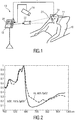
- Fig. 1 shows a schematic diagram of a system 10 according to the present invention including a device 12 for determining a vital sign information (in particular a vital sign information signal) of a subject 14 from detected electromagnetic radiation transmitted through or reflected from a subject.
- the subject 14 in this example a patient, lies in a bed 16, e.g. in a hospital or other healthcare facility, but may also be a neonate or premature infant, e.g. lying in an incubator, or person at home or in a different environment, such as an athlete doing sports.
- the vital sign information to be determined shall be respiration information, such as the respiration rate, which is preferably represented by a respiration signal.
- respiration information may include the waveform, the intervals between exhale and inhale, the amplitude, and/or the variability of the respiratory rate.
- the invention may also be applied for determining Traube-Hering- Mayer waves (also called Mayer waves or THM waves), in which case the bandwidth of signals and/or filters may be different since THM waves are around 6 BMP, which will also be mentioned below.
- a detector for detecting electromagnetic radiation transmitted through or reflected from a subject which may alternatively (which is preferred) or together be used.
- two different embodiments of the detector are shown and will be explained below.
- Both embodiments of the detector are configured for deriving at least two detection signals from the detected electromagnetic radiation, wherein each detection signal comprises wavelength-dependent reflection or transmission information in a different wavelength channel.
- optical filters used are preferably different, but can be overlapping. It is sufficient if their wavelength-dependent transmission is different.
- the detector comprises a camera 18 (also referred to as imaging unit, or as camera-based or remote PPG sensor) including a suitable photosensor for (remotely and unobtrusively) capturing image frames of the subject 14, in particular for acquiring a sequence of image frames of the subject 14 over time, from which photoplethysmography signals can be derived.
- the image frames captured by the camera 18 may particularly correspond to a video sequence captured by means of an analog or digital photosensor, e.g. in a (digital) camera.
- a camera 18 usually includes a photosensor, such as a CMOS or CCD sensor, which may also operate in a specific spectral range (visible, IR) or provide information for different spectral ranges.
- the camera 18 may provide an analog or digital signal.
- the image frames include a plurality of image pixels having associated pixel values. Particularly, the image frames include pixels representing light intensity values captured with different photosensitive elements of a photosensor. These photosensitive elements may be sensitive in a specific spectral range (i.e. representing a specific color).
- the image frames include at least some image pixels being representative of a skin portion of the subject. Thereby, an image pixel may correspond to one photosensitive element of a photodetector and its (analog or digital) output or may be determined based on a combination (e.g. through binning) of a plurality of the photosensitive elements.
- the detector comprises one or more optical photoplethysmography sensor(s) 19 (also referred to as contact PPG sensor(s)) configured for being mounted to a skin portion of the subject 14 for acquiring photoplethysmography signals.
- the PPG sensor(s) 19 may e.g. be designed in the form of a patch attached to a subject's forehead for measuring the blood oxygen saturation or a heart rate sensor for measuring the heart rate, just to name a few of all the possible embodiments.
- the system 10 may further optionally comprise a light source 22 (also called illumination source), such as a lamp, for illuminating a region of interest 24, such as the skin of the patient's face (e.g. part of the cheek or forehead), with light, for instance in a predetermined wavelength range or ranges (e.g. in the red, green and/or infrared wavelength range(s)).
- a region of interest 24 such as the skin of the patient's face (e.g. part of the cheek or forehead), with light, for instance in a predetermined wavelength range or ranges (e.g. in the red, green and/or infrared wavelength range(s)).
- a predetermined wavelength range or ranges e.g. in the red, green and/or infrared wavelength range(s)
- the light reflected from said region of interest 24 in response to said illumination is detected by the camera 18.
- no dedicated light source is provided, but ambient light is used for illumination of the subject 14. From the reflected light only light in a desired wavelength ranges
- the device 12 is further connected to an interface 20 for displaying the determined information and/or for providing medical personnel with an interface to change settings of the device 12, the camera 18, the PPG sensor(s) 19, the light source 22 and/or any other parameter of the system 10.
- an interface 20 may comprise different displays, buttons, touchscreens, keyboards or other human machine interface means.
- a system 10 as illustrated in Fig. 1 may, e.g., be located in a hospital, healthcare facility, elderly care facility or the like. Apart from the monitoring of patients, the present invention may also be applied in other fields such as neonate monitoring, general surveillance applications, security monitoring or so-called live style environments, such as fitness equipment, a wearable, a handheld device like a smartphone, or the like.
- the uni- or bidirectional communication between the device 12, the camera 18, the PPG sensor(s) 19 and the interface 20 may work via a wireless or wired communication interface.
- Other embodiments of the present invention may include a device 12, which is not provided stand-alone, but integrated into the camera 18 or the interface 20.
- the beating of the heart causes pressure variations in the arteries as the heart pumps blood against the resistance of the vascular bed. Since the arteries are elastic, their diameter changes in sync with the pressure variations. These diameter changes occur even in the smaller vessels of the skin, where the blood volume variations cause a changing absorption of the light.
- the unit length normalized blood volume pulse vector (also called signature vector) is defined as P bv , providing the relative PPG-strength in the red, green and blue camera signal.
- P bv The unit length normalized blood volume pulse vector
- the precise blood volume pulse vector depends on the color filters of the camera, the spectrum of the light and the skin-reflectance, as the model shows. In practice the vector turns out to be remarkably stable though given a set of wavelength channels (the vector will be different in the infrared compared to RGB-based vector).
- the relative reflectance of the skin, in the red, green and blue channel under white illumination does not depend much on the skin-type. This is likely because the absorption spectra of the blood-free skin is dominated by the melanin absorption. Although a higher melanin concentration can increase the absolute absorption considerably, the relative absorption in the different wavelengths remains the same. This implies an increase of melanin darkens the skin, but hardly changes the normalized color of the skin. Consequently, also the normalized blood volume pulse P bv is quite stable under white illumination. In the infrared wavelengths the influence of melanin is further reduced as its maximum absorption occurs for short wavelengths (UV-light) and decreases for longer wavelengths.
- the stable character of P bv can be used to distinguish color variations caused by blood volume change from variations due to alternative causes.
- the operator ⁇ corresponds to the mean.
- the noise and the PPG signal may be separated into two independent signals built as a linear combination of two color channels. One combination approximated a clean PPG signal, the other contained noise due to motion. As an optimization criterion the energy in the pulse signal may be minimized.
- a linear combination of the three color channels may be used to obtain the pulse signal.
- the ICA or the PCA may be used to find this linear combination. Since it is a priori unknown which weighted color signal is the pulse signal all of them used the periodic nature of the pulse signal as the selection criterion.
- the P bv method generally obtains the mixing coefficients using the blood volume pulse vector as basically described in US 2013/271591 A1 and the above cited paper of de Haan and van Leest. The best results are obtained if the band-passed filtered versions of R n , G n and B n are used. According to this method the known direction of P bv is used to discriminate between the pulse signal and distortions. This not only removes the assumption (of earlier methods) that the pulse is the only periodic component in the video, but also eliminates assumptions on the orientation of the distortion signals. To this end, it is assumed as before that the pulse signal is built as a linear combination of normalized color signals.
- P bv the characteristic wavelength dependency of the PPG signal, as reflected in the normalized blood volume pulse, P bv , can be used to estimate the pulse signal from the time-sequential RGB pixel data averaged over the skin area. This algorithm is referred to as the P bv method.
- a pulse signal results as a weighted sum of the at least two detection signals C n . Since all detection signals C n contain the pulse and different levels of (common) noise, the weighting (of the detection signals to obtain the pulse signal) can lead to a pure noise-free pulse. This is why ICA and PCA can be used to separate noise and pulse. According to the present invention this is done differently.
- the absorption spectrum of blood depends on the oxygen saturation, particularly in the wavelengths around 650nm. This causes the respiration to induce a slightly stronger absorption change in the red wavelength range. It is clear from Fig. 2 though that the absorption in the green wavelength range (around 550nm) and blue wavelength range (around 450nm) is much higher.
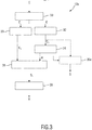
- Fig. 3 shows a schematic illustration of a first embodiment 12a of the device 12 according to the present invention.
- the device 12a comprises an input interface 30 for obtaining at least two detection signals C derived from detected electromagnetic radiation transmitted through or reflected from a skin region of the subject 14.
- the data stream of detection data i.e. the detection signals C, is e.g. provided by the camera 18 and/or one or more PPG sensor(s) 19, wherein each detection signal comprises wavelength-dependent reflection or transmission information in a different wavelength channel.
- a first filter unit 32 filter said at least two detection signals C with a first filter to obtain at least two first bandwidth-limited detection signals C f1 .
- a weight computation unit 34 computes weights w resulting, when applied in a weighted combination of said at least two first bandwidth-limited detection signals C f1 , in a first vital sign signal S 1 having reduced distortions.
- the first vital sign signal S 1 is thereby not necessarily determined, but only the weights w are actually determined.
- the first vital sign signals is only determined in certain embodiments.
- a second filter unit 33 filters said at least two detection signals C with a second filter to obtain at least two second bandwidth-limited detection signals C f2 .
- the second filter is configured such that the second bandwidth-limited detection signals C f2 are differently bandwidth-limited than said first bandwidth-limited detection signals C f1 and particularly include the frequency range of said vital sign information (e.g. of a respiration signal and/or Mayer waves).
- a vital sign signal computation unit 36 computes a second vital sign signal S 2 using the computed weights w and said at least two second bandwidth-limited detection signals C f2 .
- the second vital sign signal S 2 is hereby preferably computed by a weighted combination of the at least two second bandwidth-limited detection signals C f2 using the computed weights w.
- first bandwidth-limited signals may include only the frequency range of pulse frequencies or additionally of respiration frequencies
- second bandwidth-limited signals may include only the frequency range of respiration frequencies
- a vital sign determination unit 38 finally determines vital sign information V from said second vital sign signal S 2 .
- An optional good choice for P bv [0.33, 0.77, 0.53], but other choices (e.g. as described above) are possible as well.
- This first filter is designed to include the range of pulse rates, e.g. 100-180 BPM for a neonate, or 40-220BPM for an adult subject.
- the range also includes the range of respiratory frequencies to make sure that also low frequency distortions are eliminated as much as possible (indicated by the notation C fr + fp ). This may lead to a filter design passing frequencies in a range from 10-200 BPM.
- first vital sign signal S 1 W PBV C fr + fp
- the calculation of the first vital sign signal S 1 is not mandatory, as represented by the schematic diagram shown in Fig. 3 .
- the first vital sign signal S 1 may also be determined by the vital sign signal computation unit, represented in broken lines by the unit 36a is Fig. 3 , as a weighted combination of said at least two first bandwidth-limited detection signals C f1 using the computed weights w.
- the pass-band of this second filter only includes the expected respiratory frequencies, e.g. between 8 and 30 BPM for an adult, or 20-60 BPM for a neonate.
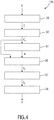
- Fig. 4 shows a schematic illustration of a second embodiment 12b of the device 12 according to the present invention.
- the vital sign signal computation unit 38 is configured to compute the second vital sign signal S 2 using the computed weights w and said first bandwidth-limited detection signals C f1 , which, in this embodiment, preferably include the frequency range of said second vital sign signal in addition to the frequency range of the pulse signal.
- the computation of the second vital sign signal S 2 is particularly performed in two steps.
- the vital sign signal computation unit 36 computes a first vital sign signal S 1 by a weighted combination of said at least two first bandwidth-limited detection signals C f1 using the computed weights w.
- a second filter unit 37 (which may be part of the vital sign signal computation unit 36) filters said first vital sign signal S 1 with a second filter to obtain said second vital sign signal S 2 .
- the second vital sign signal S 2 can be obtained by re-filtering the first vital sign signal S 1 with the second filter.
- the second filter unit 37 is preferably configured to let at least the frequency range of a subject's respiration signal and/or Mayer waves pass and suppress at least the frequency range of a subject's pulse signal, in particular to let a frequency range pass having a lower limit in the range of 5-25 BPM, in particular 10-20 BPM, and an upper limit in the range of 25-70 BPM, in particular 30-60 BPM.
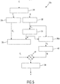
- Fig. 5 shows a schematic illustration of a third embodiment 12c of the device 12 according to the present invention.
- the first vital sign signal S 1 and the second vital sign signal S 2 are computed as illustrated above in the first (or second) embodiment.
- a peak detector 40 is provided for peak detection to determine the amplitude of first vital sign signal S 1 . This may be done in the time domain by computing the amplitude/standard deviation of the first vital sign signal S 1 , possibly after bandpass-filtering it to prevent influence of noise, or in the frequency domain by computing the RMS-value of the frequency bins around the pulse rate.
- the idea hereby is to use the amplitude of the pulse to set the gain G for the second vital sign signal S 2 (e.g. the respiration signal).
- the inverse of this amplitude is used to normalize the amplitude of the second vital sign signal S 2 by multiplication of the second vital sign signal S 2 with the gain G in a multiplication unit 42 to obtain a normalized second vital sign signal S 2 , from which the desired vital sign information V can then be derived.
- the resulting gain should be inversely proportional to the amplitude of the first vital sign signal S 1 .
- the peak detector may be particularly configured to limit the peak detection to a frequency range of a subject's pulse signal. Hence, the strength of the pulse signal is used to determine the gain needed to show the desired vital sign information signal with a substantially constant relative amplitude.
- peak detection may be performed in the Fourier domain of the first vital sign signal, limiting the frequency range, for peak detection, to the pulse frequencies.
- the second vital sign is then obtained as described above, but its amplitude is modified with a gain factor.
- the above described processing uses an overlap-add-process, as described in the above cited paper of G. de Haan and A. van Leest, "Improved motion robustness of remote-PPG by using the blood volume pulse signature", where at least the optimization of equation (1) is performed on short intervals, typically a few seconds, to allow for distortion elimination even with changing statistics of the distortions over time. Also the above described synthesizing of the second vital sign signal from the first vital sign signal is performed on each interval. In case of filtering to obtain the second vital sign signal, this can also be performed after the overlap-add procedure.
- the time-varying (fixed on each overlap-add interval) gain, k, of the output signal, which is included in the weighting vector W PBV can be selected such that the pulse signal in the first vital sign signal has a constant amplitude, e.g. by dividing the signals by the standard deviation of the first signal in the frequency band of the pulse signal.
- third band-width limited detection signals C fp i.e.
- the weights are calculated from the color signals filtered to include at least the pulse signal variations, while the respiration signal is derived from the color signals using the same weights, but a different filtering.
- the gain control can be derived from the standard deviation of the pulse signal, regardless the initial method used to derive the weighing vector.
- said weight computation unit 34 may be configured to compute the weights w such that
- the available skin area is divided into sub-regions and the aforementioned processing is performed per sub-region.
- This process leads to multiple candidate signals, S 1 and S 2 , which can be directly combined into a final respiration signal (when only combining S 2 ), or from which the respiration signal can be derived by filtering (when combining S 1 ).
- the combining process may be a median, or trimmed-mean filtering, rejecting outliers, or can be a weighted average with weights e.g. determined by the variance, in the time domain, of the individual signals (this assumes that a high variance implies a high residual distortion).
- the weight computation unit 34 computes weights w per set of at least two detection signals C acquired from different sub-regions.
- the vital sign signal computation unit 36 then computes, per set of at least two detection signals C, a first preliminary vital sign signal by a weighted combination of said at least two first bandwidth-limited detection signals C f1 using the computed weights w of the respective set of at least two detection signals C and to compute said first vital sign signal S 1 by combining said first preliminary vital sign signal.
- the second filter unit 37 filters said first vital sign signal S 1 with a second filter to obtain said second vital sign signal S 2 .
- the weights to minimize distortions are calculated for both the individual sub-regions and the entire skin area. These weights are consequently used to extract signals from these (sub-) regions including both respiration and pulse information. Selecting the best weights is accomplished by calculating the signal-to-noise ratio (SNR) of each region. By ranking the signals based on their SNRs, the final weights are selected, as either the weights corresponding to the signal with the highest SNR, or a combination of the weights corresponding to the signals (two or more) with the highest SNR. These final weights are then applied to the filtered, normalized traces of the entire skin region, containing only respiration information.
- SNR signal-to-noise ratio
- the present invention can be applied in the field of health care, e.g. unobtrusive remote patient monitoring, general surveillances, security monitoring and so-called lifestyle environments, such as fitness equipment, or the like. Applications may include monitoring of oxygen saturation (pulse oximetry), heart rate, blood pressure, cardiac output, respiration, Mayer waves, changes of blood perfusion, assessment of autonomic functions, and detection of peripheral vascular diseases.
- the present invention can e.g. be used for rapid and reliable respiration monitoring and detection of a critical patient.
- the system can be used for monitoring of vital signs of neonates as well.
- the present invention improves the SNR considerably for near stationary subjects and consequently leads to a more accurate beat-to-beat measurement.
- a computer program may be stored/distributed on a suitable medium, such as an optical storage medium or a solid-state medium supplied together with or as part of other hardware, but may also be distributed in other forms, such as via the Internet or other wired or wireless telecommunication systems.
- a suitable medium such as an optical storage medium or a solid-state medium supplied together with or as part of other hardware, but may also be distributed in other forms, such as via the Internet or other wired or wireless telecommunication systems.
Landscapes
- Health & Medical Sciences (AREA)
- Life Sciences & Earth Sciences (AREA)
- Engineering & Computer Science (AREA)
- Cardiology (AREA)
- Physiology (AREA)
- Surgery (AREA)
- General Health & Medical Sciences (AREA)
- Biophysics (AREA)
- Biomedical Technology (AREA)
- Heart & Thoracic Surgery (AREA)
- Medical Informatics (AREA)
- Molecular Biology (AREA)
- Physics & Mathematics (AREA)
- Animal Behavior & Ethology (AREA)
- Pathology (AREA)
- Public Health (AREA)
- Veterinary Medicine (AREA)
- Signal Processing (AREA)
- Artificial Intelligence (AREA)
- Computer Vision & Pattern Recognition (AREA)
- Psychiatry (AREA)
- Pulmonology (AREA)
- Measuring Pulse, Heart Rate, Blood Pressure Or Blood Flow (AREA)
- Measuring And Recording Apparatus For Diagnosis (AREA)
Applications Claiming Priority (2)
| Application Number | Priority Date | Filing Date | Title |
|---|---|---|---|
| EP15197218 | 2015-12-01 | ||
| PCT/EP2016/079390 WO2017093379A1 (en) | 2015-12-01 | 2016-12-01 | Device, system and method for determining vital sign information of a subject |
Publications (2)
| Publication Number | Publication Date |
|---|---|
| EP3383258A1 EP3383258A1 (en) | 2018-10-10 |
| EP3383258B1 true EP3383258B1 (en) | 2019-06-05 |
Family
ID=54754559
Family Applications (1)
| Application Number | Title | Priority Date | Filing Date |
|---|---|---|---|
| EP16805781.8A Active EP3383258B1 (en) | 2015-12-01 | 2016-12-01 | Device, system and method for determining vital sign information of a subject |
Country Status (5)
| Country | Link |
|---|---|
| US (1) | US20180333102A1 (enExample) |
| EP (1) | EP3383258B1 (enExample) |
| JP (1) | JP6654700B2 (enExample) |
| CN (1) | CN108471962B (enExample) |
| WO (1) | WO2017093379A1 (enExample) |
Families Citing this family (33)
| Publication number | Priority date | Publication date | Assignee | Title |
|---|---|---|---|---|
| US10667723B2 (en) | 2016-02-19 | 2020-06-02 | Covidien Lp | Systems and methods for video-based monitoring of vital signs |
| US10653523B2 (en) | 2017-01-19 | 2020-05-19 | 4C Medical Technologies, Inc. | Systems, methods and devices for delivery systems, methods and devices for implanting prosthetic heart valves |
| US10561495B2 (en) | 2017-01-24 | 2020-02-18 | 4C Medical Technologies, Inc. | Systems, methods and devices for two-step delivery and implantation of prosthetic heart valve |
| US12029647B2 (en) | 2017-03-07 | 2024-07-09 | 4C Medical Technologies, Inc. | Systems, methods and devices for prosthetic heart valve with single valve leaflet |
| EP3440991A1 (en) * | 2017-08-08 | 2019-02-13 | Koninklijke Philips N.V. | Device, system and method for determining a physiological parameter of a subject |
| EP3479754A1 (en) * | 2017-11-01 | 2019-05-08 | Koninklijke Philips N.V. | Device, system and method for determining at least one vital sign of a subject |
| EP3681394A1 (en) | 2017-11-13 | 2020-07-22 | Covidien LP | Systems and methods for video-based monitoring of a patient |
| US11712176B2 (en) | 2018-01-08 | 2023-08-01 | Covidien, LP | Systems and methods for video-based non-contact tidal volume monitoring |
| CN111919236A (zh) * | 2018-02-23 | 2020-11-10 | 艾卢诺斯公司 | 生理参数的监测 |
| WO2019240991A1 (en) | 2018-06-15 | 2019-12-19 | Covidien Lp | Systems and methods for video-based patient monitoring during surgery |
| US11311252B2 (en) | 2018-08-09 | 2022-04-26 | Covidien Lp | Video-based patient monitoring systems and associated methods for detecting and monitoring breathing |
| US11857441B2 (en) | 2018-09-04 | 2024-01-02 | 4C Medical Technologies, Inc. | Stent loading device |
| US11000198B2 (en) * | 2018-12-05 | 2021-05-11 | Viavi Solutions Inc. | Autonomous full spectrum biometric monitoring |
| US11617520B2 (en) | 2018-12-14 | 2023-04-04 | Covidien Lp | Depth sensing visualization modes for non-contact monitoring |
| US11315275B2 (en) | 2019-01-28 | 2022-04-26 | Covidien Lp | Edge handling methods for associated depth sensing camera devices, systems, and methods |
| EP3698704A1 (en) * | 2019-02-20 | 2020-08-26 | Koninklijke Philips N.V. | Device, system and method for determining physiological information |
| US11452628B2 (en) | 2019-04-15 | 2022-09-27 | 4C Medical Technologies, Inc. | Loading systems for collapsible prosthetic heart valve devices and methods thereof |
| CN110558966A (zh) * | 2019-08-12 | 2019-12-13 | 平安科技(深圳)有限公司 | 一种脉搏检测装置 |
| EP4033495B1 (en) * | 2019-09-17 | 2026-01-21 | Cyberdyne Inc. | Behavior task evaluation system and behavior task evaluation method |
| US11931253B2 (en) | 2020-01-31 | 2024-03-19 | 4C Medical Technologies, Inc. | Prosthetic heart valve delivery system: ball-slide attachment |
| US12133797B2 (en) | 2020-01-31 | 2024-11-05 | 4C Medical Technologies, Inc. | Prosthetic heart valve delivery system: paddle attachment feature |
| US12053375B2 (en) | 2020-03-05 | 2024-08-06 | 4C Medical Technologies, Inc. | Prosthetic mitral valve with improved atrial and/or annular apposition and paravalvular leakage mitigation |
| US11992403B2 (en) | 2020-03-06 | 2024-05-28 | 4C Medical Technologies, Inc. | Devices, systems and methods for improving recapture of prosthetic heart valve device with stent frame having valve support with inwardly stent cells |
| IL275524B (en) | 2020-06-18 | 2021-12-01 | Elbit Systems C4I & Cyber Ltd | System and method for measuring parameters without contact |
| US11850026B2 (en) | 2020-06-24 | 2023-12-26 | The Governing Council Of The University Of Toronto | Remote portable vital signs monitoring |
| US12357194B2 (en) | 2020-07-09 | 2025-07-15 | Covidien Lp | Informative display for non-contact patient monitoring |
| US12514468B2 (en) | 2020-12-02 | 2026-01-06 | Covidien Lp | Patient position monitoring methods and systems |
| US12390124B2 (en) | 2021-01-27 | 2025-08-19 | Covidien Lp | Systems and methods for non-contact respiratory monitoring |
| US20230084864A1 (en) * | 2021-09-15 | 2023-03-16 | Anhui Huami Health Technology Co., Ltd. | Method And Device That Generates A Respiration Signal |
| US12490904B2 (en) | 2021-10-08 | 2025-12-09 | Covidien Lp | Enhanced image for non-contact monitoring |
| US12482557B2 (en) | 2021-12-09 | 2025-11-25 | Covidien Lp | Systems and methods for improved non-contact patient monitoring of incubated neonates |
| US12374128B2 (en) * | 2021-12-21 | 2025-07-29 | Covidien Lp | Non-contact depth sensing monitoring in vehicles |
| SE545755C2 (en) * | 2022-02-25 | 2024-01-02 | Detectivio Ab | Non-contact oxygen saturation estimation |
Family Cites Families (20)
| Publication number | Priority date | Publication date | Assignee | Title |
|---|---|---|---|---|
| US4958638A (en) * | 1988-06-30 | 1990-09-25 | Georgia Tech Research Corporation | Non-contact vital signs monitor |
| FR2811214B1 (fr) * | 2000-07-05 | 2003-01-31 | R B I | Procede et dispositif de determination de parametres physiologiques cardio-respiratoires |
| US6702752B2 (en) * | 2002-02-22 | 2004-03-09 | Datex-Ohmeda, Inc. | Monitoring respiration based on plethysmographic heart rate signal |
| FI120619B (fi) * | 2006-11-17 | 2009-12-31 | Suunto Oy | Laite ja menetelmä suorituksen seuraamiseksi |
| US10420476B2 (en) * | 2009-09-15 | 2019-09-24 | Sotera Wireless, Inc. | Body-worn vital sign monitor |
| CN102576458B (zh) * | 2009-10-06 | 2015-08-19 | 皇家飞利浦电子股份有限公司 | 用于获得第一信号进行分析以便表征该第一信号的至少一个周期性分量的方法和系统 |
| US20120029320A1 (en) * | 2010-07-30 | 2012-02-02 | Nellcor Puritan Bennett Llc | Systems and methods for processing multiple physiological signals |
| TWI548397B (zh) * | 2011-01-05 | 2016-09-11 | 皇家飛利浦電子股份有限公司 | 用以自特徵信號擷取資訊之裝置及方法 |
| US9713428B2 (en) * | 2011-01-21 | 2017-07-25 | Worcester Polytechnic Institute | Physiological parameter monitoring with a mobile communication device |
| WO2012140531A1 (en) * | 2011-04-14 | 2012-10-18 | Koninklijke Philips Electronics N.V. | Device and method for extracting information from characteristic signals |
| JP5672144B2 (ja) * | 2011-05-20 | 2015-02-18 | 富士通株式会社 | 心拍数・呼吸数検出装置,方法およびプログラム |
| BR112014004064A2 (pt) * | 2011-08-26 | 2017-03-14 | Koninklijke Philips Nv | dispositivo e método para a extração de informações de sinais característicos detectados e programa de computador |
| WO2013038326A1 (en) * | 2011-09-13 | 2013-03-21 | Koninklijke Philips Electronics N.V. | Distortion reduced signal detection |
| US9675274B2 (en) * | 2011-09-23 | 2017-06-13 | Nellcor Puritan Bennett Ireland | Systems and methods for determining respiration information from a photoplethysmograph |
| WO2014024104A1 (en) * | 2012-08-06 | 2014-02-13 | Koninklijke Philips N.V. | Device and method for extracting physiological information |
| BR112015022002A2 (pt) * | 2013-03-13 | 2017-07-18 | Koninklijke Philips Nv | aparelho para determinar informações de sinais vitais de um indivíduo, e método para determinar informações de sinais vitais de um indivíduo |
| CN105050492B (zh) * | 2013-03-14 | 2019-01-08 | 皇家飞利浦有限公司 | 用于确定对象的生命体征的设备和方法 |
| RU2675036C2 (ru) * | 2013-03-14 | 2018-12-14 | Конинклейке Филипс Н.В. | Устройство и способ получения информации о показателях жизненно важных функций субъекта |
| US20140275825A1 (en) * | 2013-03-15 | 2014-09-18 | Covidien Lp | Methods and systems for light signal control in a physiological monitor |
| RU2015156254A (ru) * | 2014-05-07 | 2017-07-04 | Конинклейке Филипс Н.В. | Устройство, система и способ выделения физиологической информации |
-
2016
- 2016-12-01 CN CN201680077231.XA patent/CN108471962B/zh active Active
- 2016-12-01 WO PCT/EP2016/079390 patent/WO2017093379A1/en not_active Ceased
- 2016-12-01 US US15/777,231 patent/US20180333102A1/en not_active Abandoned
- 2016-12-01 EP EP16805781.8A patent/EP3383258B1/en active Active
- 2016-12-01 JP JP2018527954A patent/JP6654700B2/ja active Active
Non-Patent Citations (1)
| Title |
|---|
| None * |
Also Published As
| Publication number | Publication date |
|---|---|
| CN108471962B (zh) | 2021-04-20 |
| JP2019500932A (ja) | 2019-01-17 |
| US20180333102A1 (en) | 2018-11-22 |
| WO2017093379A1 (en) | 2017-06-08 |
| EP3383258A1 (en) | 2018-10-10 |
| CN108471962A (zh) | 2018-08-31 |
| JP6654700B2 (ja) | 2020-02-26 |
Similar Documents
| Publication | Publication Date | Title |
|---|---|---|
| EP3383258B1 (en) | Device, system and method for determining vital sign information of a subject | |
| US12064269B2 (en) | Device, system and method for generating a photoplethysmographic image carrying vital sign information of a subject | |
| EP2988662B1 (en) | System and method for extracting physiological information | |
| EP3355787B1 (en) | Device, system and method for extracting physiological information | |
| EP3479754A1 (en) | Device, system and method for determining at least one vital sign of a subject | |
| US10478078B2 (en) | Device and method for determining vital signs of a subject | |
| JP7065845B6 (ja) | 被検体のバイタルサインを得るためのデバイス、システム、方法、及びコンピュータプログラム | |
| CN113498326B (zh) | 用于确定生理信息的设备、系统和方法 | |
| EP3422931B1 (en) | Device, system and method for determining a vital sign of a subject | |
| US11712185B2 (en) | Device, system and method for extracting physiological information indicative of at least one vital sign of a subject | |
| EP3517034A1 (en) | Device, system and method for determining at least one vital sign of a subject |
Legal Events
| Date | Code | Title | Description |
|---|---|---|---|
| STAA | Information on the status of an ep patent application or granted ep patent |
Free format text: STATUS: UNKNOWN |
|
| STAA | Information on the status of an ep patent application or granted ep patent |
Free format text: STATUS: THE INTERNATIONAL PUBLICATION HAS BEEN MADE |
|
| PUAI | Public reference made under article 153(3) epc to a published international application that has entered the european phase |
Free format text: ORIGINAL CODE: 0009012 |
|
| STAA | Information on the status of an ep patent application or granted ep patent |
Free format text: STATUS: REQUEST FOR EXAMINATION WAS MADE |
|
| 17P | Request for examination filed |
Effective date: 20180702 |
|
| AK | Designated contracting states |
Kind code of ref document: A1 Designated state(s): AL AT BE BG CH CY CZ DE DK EE ES FI FR GB GR HR HU IE IS IT LI LT LU LV MC MK MT NL NO PL PT RO RS SE SI SK SM TR |
|
| AX | Request for extension of the european patent |
Extension state: BA ME |
|
| GRAP | Despatch of communication of intention to grant a patent |
Free format text: ORIGINAL CODE: EPIDOSNIGR1 |
|
| STAA | Information on the status of an ep patent application or granted ep patent |
Free format text: STATUS: GRANT OF PATENT IS INTENDED |
|
| INTG | Intention to grant announced |
Effective date: 20190108 |
|
| INTG | Intention to grant announced |
Effective date: 20190108 |
|
| DAV | Request for validation of the european patent (deleted) | ||
| DAX | Request for extension of the european patent (deleted) | ||
| GRAS | Grant fee paid |
Free format text: ORIGINAL CODE: EPIDOSNIGR3 |
|
| GRAA | (expected) grant |
Free format text: ORIGINAL CODE: 0009210 |
|
| STAA | Information on the status of an ep patent application or granted ep patent |
Free format text: STATUS: THE PATENT HAS BEEN GRANTED |
|
| AK | Designated contracting states |
Kind code of ref document: B1 Designated state(s): AL AT BE BG CH CY CZ DE DK EE ES FI FR GB GR HR HU IE IS IT LI LT LU LV MC MK MT NL NO PL PT RO RS SE SI SK SM TR |
|
| REG | Reference to a national code |
Ref country code: GB Ref legal event code: FG4D |
|
| REG | Reference to a national code |
Ref country code: CH Ref legal event code: EP |
|
| REG | Reference to a national code |
Ref country code: AT Ref legal event code: REF Ref document number: 1139181 Country of ref document: AT Kind code of ref document: T Effective date: 20190615 |
|
| REG | Reference to a national code |
Ref country code: IE Ref legal event code: FG4D |
|
| REG | Reference to a national code |
Ref country code: DE Ref legal event code: R096 Ref document number: 602016014942 Country of ref document: DE |
|
| REG | Reference to a national code |
Ref country code: NL Ref legal event code: MP Effective date: 20190605 |
|
| REG | Reference to a national code |
Ref country code: LT Ref legal event code: MG4D |
|
| PG25 | Lapsed in a contracting state [announced via postgrant information from national office to epo] |
Ref country code: SE Free format text: LAPSE BECAUSE OF FAILURE TO SUBMIT A TRANSLATION OF THE DESCRIPTION OR TO PAY THE FEE WITHIN THE PRESCRIBED TIME-LIMIT Effective date: 20190605 Ref country code: LT Free format text: LAPSE BECAUSE OF FAILURE TO SUBMIT A TRANSLATION OF THE DESCRIPTION OR TO PAY THE FEE WITHIN THE PRESCRIBED TIME-LIMIT Effective date: 20190605 Ref country code: HR Free format text: LAPSE BECAUSE OF FAILURE TO SUBMIT A TRANSLATION OF THE DESCRIPTION OR TO PAY THE FEE WITHIN THE PRESCRIBED TIME-LIMIT Effective date: 20190605 Ref country code: ES Free format text: LAPSE BECAUSE OF FAILURE TO SUBMIT A TRANSLATION OF THE DESCRIPTION OR TO PAY THE FEE WITHIN THE PRESCRIBED TIME-LIMIT Effective date: 20190605 Ref country code: NO Free format text: LAPSE BECAUSE OF FAILURE TO SUBMIT A TRANSLATION OF THE DESCRIPTION OR TO PAY THE FEE WITHIN THE PRESCRIBED TIME-LIMIT Effective date: 20190905 Ref country code: AL Free format text: LAPSE BECAUSE OF FAILURE TO SUBMIT A TRANSLATION OF THE DESCRIPTION OR TO PAY THE FEE WITHIN THE PRESCRIBED TIME-LIMIT Effective date: 20190605 Ref country code: FI Free format text: LAPSE BECAUSE OF FAILURE TO SUBMIT A TRANSLATION OF THE DESCRIPTION OR TO PAY THE FEE WITHIN THE PRESCRIBED TIME-LIMIT Effective date: 20190605 |
|
| PG25 | Lapsed in a contracting state [announced via postgrant information from national office to epo] |
Ref country code: BG Free format text: LAPSE BECAUSE OF FAILURE TO SUBMIT A TRANSLATION OF THE DESCRIPTION OR TO PAY THE FEE WITHIN THE PRESCRIBED TIME-LIMIT Effective date: 20190905 Ref country code: RS Free format text: LAPSE BECAUSE OF FAILURE TO SUBMIT A TRANSLATION OF THE DESCRIPTION OR TO PAY THE FEE WITHIN THE PRESCRIBED TIME-LIMIT Effective date: 20190605 Ref country code: LV Free format text: LAPSE BECAUSE OF FAILURE TO SUBMIT A TRANSLATION OF THE DESCRIPTION OR TO PAY THE FEE WITHIN THE PRESCRIBED TIME-LIMIT Effective date: 20190605 Ref country code: GR Free format text: LAPSE BECAUSE OF FAILURE TO SUBMIT A TRANSLATION OF THE DESCRIPTION OR TO PAY THE FEE WITHIN THE PRESCRIBED TIME-LIMIT Effective date: 20190906 |
|
| REG | Reference to a national code |
Ref country code: AT Ref legal event code: MK05 Ref document number: 1139181 Country of ref document: AT Kind code of ref document: T Effective date: 20190605 |
|
| PG25 | Lapsed in a contracting state [announced via postgrant information from national office to epo] |
Ref country code: NL Free format text: LAPSE BECAUSE OF FAILURE TO SUBMIT A TRANSLATION OF THE DESCRIPTION OR TO PAY THE FEE WITHIN THE PRESCRIBED TIME-LIMIT Effective date: 20190605 Ref country code: PT Free format text: LAPSE BECAUSE OF FAILURE TO SUBMIT A TRANSLATION OF THE DESCRIPTION OR TO PAY THE FEE WITHIN THE PRESCRIBED TIME-LIMIT Effective date: 20191007 Ref country code: RO Free format text: LAPSE BECAUSE OF FAILURE TO SUBMIT A TRANSLATION OF THE DESCRIPTION OR TO PAY THE FEE WITHIN THE PRESCRIBED TIME-LIMIT Effective date: 20190605 Ref country code: SK Free format text: LAPSE BECAUSE OF FAILURE TO SUBMIT A TRANSLATION OF THE DESCRIPTION OR TO PAY THE FEE WITHIN THE PRESCRIBED TIME-LIMIT Effective date: 20190605 Ref country code: CZ Free format text: LAPSE BECAUSE OF FAILURE TO SUBMIT A TRANSLATION OF THE DESCRIPTION OR TO PAY THE FEE WITHIN THE PRESCRIBED TIME-LIMIT Effective date: 20190605 Ref country code: EE Free format text: LAPSE BECAUSE OF FAILURE TO SUBMIT A TRANSLATION OF THE DESCRIPTION OR TO PAY THE FEE WITHIN THE PRESCRIBED TIME-LIMIT Effective date: 20190605 Ref country code: AT Free format text: LAPSE BECAUSE OF FAILURE TO SUBMIT A TRANSLATION OF THE DESCRIPTION OR TO PAY THE FEE WITHIN THE PRESCRIBED TIME-LIMIT Effective date: 20190605 |
|
| PG25 | Lapsed in a contracting state [announced via postgrant information from national office to epo] |
Ref country code: IS Free format text: LAPSE BECAUSE OF FAILURE TO SUBMIT A TRANSLATION OF THE DESCRIPTION OR TO PAY THE FEE WITHIN THE PRESCRIBED TIME-LIMIT Effective date: 20191005 Ref country code: IT Free format text: LAPSE BECAUSE OF FAILURE TO SUBMIT A TRANSLATION OF THE DESCRIPTION OR TO PAY THE FEE WITHIN THE PRESCRIBED TIME-LIMIT Effective date: 20190605 Ref country code: SM Free format text: LAPSE BECAUSE OF FAILURE TO SUBMIT A TRANSLATION OF THE DESCRIPTION OR TO PAY THE FEE WITHIN THE PRESCRIBED TIME-LIMIT Effective date: 20190605 |
|
| REG | Reference to a national code |
Ref country code: DE Ref legal event code: R097 Ref document number: 602016014942 Country of ref document: DE |
|
| RAP2 | Party data changed (patent owner data changed or rights of a patent transferred) |
Owner name: TECHNISCHE UNIVERSITEIT EINDHOVEN Owner name: KONINKLIJKE PHILIPS N.V. |
|
| PG25 | Lapsed in a contracting state [announced via postgrant information from national office to epo] |
Ref country code: TR Free format text: LAPSE BECAUSE OF FAILURE TO SUBMIT A TRANSLATION OF THE DESCRIPTION OR TO PAY THE FEE WITHIN THE PRESCRIBED TIME-LIMIT Effective date: 20190605 |
|
| PLBE | No opposition filed within time limit |
Free format text: ORIGINAL CODE: 0009261 |
|
| STAA | Information on the status of an ep patent application or granted ep patent |
Free format text: STATUS: NO OPPOSITION FILED WITHIN TIME LIMIT |
|
| PG25 | Lapsed in a contracting state [announced via postgrant information from national office to epo] |
Ref country code: PL Free format text: LAPSE BECAUSE OF FAILURE TO SUBMIT A TRANSLATION OF THE DESCRIPTION OR TO PAY THE FEE WITHIN THE PRESCRIBED TIME-LIMIT Effective date: 20190605 Ref country code: DK Free format text: LAPSE BECAUSE OF FAILURE TO SUBMIT A TRANSLATION OF THE DESCRIPTION OR TO PAY THE FEE WITHIN THE PRESCRIBED TIME-LIMIT Effective date: 20190605 |
|
| 26N | No opposition filed |
Effective date: 20200306 |
|
| REG | Reference to a national code |
Ref country code: CH Ref legal event code: PL |
|
| REG | Reference to a national code |
Ref country code: BE Ref legal event code: MM Effective date: 20191231 |
|
| PG25 | Lapsed in a contracting state [announced via postgrant information from national office to epo] |
Ref country code: MC Free format text: LAPSE BECAUSE OF FAILURE TO SUBMIT A TRANSLATION OF THE DESCRIPTION OR TO PAY THE FEE WITHIN THE PRESCRIBED TIME-LIMIT Effective date: 20190605 |
|
| PG25 | Lapsed in a contracting state [announced via postgrant information from national office to epo] |
Ref country code: LU Free format text: LAPSE BECAUSE OF NON-PAYMENT OF DUE FEES Effective date: 20191201 Ref country code: IE Free format text: LAPSE BECAUSE OF NON-PAYMENT OF DUE FEES Effective date: 20191201 |
|
| PG25 | Lapsed in a contracting state [announced via postgrant information from national office to epo] |
Ref country code: BE Free format text: LAPSE BECAUSE OF NON-PAYMENT OF DUE FEES Effective date: 20191231 Ref country code: LI Free format text: LAPSE BECAUSE OF NON-PAYMENT OF DUE FEES Effective date: 20191231 Ref country code: CH Free format text: LAPSE BECAUSE OF NON-PAYMENT OF DUE FEES Effective date: 20191231 |
|
| PG25 | Lapsed in a contracting state [announced via postgrant information from national office to epo] |
Ref country code: CY Free format text: LAPSE BECAUSE OF FAILURE TO SUBMIT A TRANSLATION OF THE DESCRIPTION OR TO PAY THE FEE WITHIN THE PRESCRIBED TIME-LIMIT Effective date: 20190605 |
|
| PG25 | Lapsed in a contracting state [announced via postgrant information from national office to epo] |
Ref country code: MT Free format text: LAPSE BECAUSE OF FAILURE TO SUBMIT A TRANSLATION OF THE DESCRIPTION OR TO PAY THE FEE WITHIN THE PRESCRIBED TIME-LIMIT Effective date: 20190605 Ref country code: HU Free format text: LAPSE BECAUSE OF FAILURE TO SUBMIT A TRANSLATION OF THE DESCRIPTION OR TO PAY THE FEE WITHIN THE PRESCRIBED TIME-LIMIT; INVALID AB INITIO Effective date: 20161201 |
|
| GBPC | Gb: european patent ceased through non-payment of renewal fee |
Effective date: 20201201 |
|
| PG25 | Lapsed in a contracting state [announced via postgrant information from national office to epo] |
Ref country code: SI Free format text: LAPSE BECAUSE OF FAILURE TO SUBMIT A TRANSLATION OF THE DESCRIPTION OR TO PAY THE FEE WITHIN THE PRESCRIBED TIME-LIMIT Effective date: 20190605 |
|
| PG25 | Lapsed in a contracting state [announced via postgrant information from national office to epo] |
Ref country code: GB Free format text: LAPSE BECAUSE OF NON-PAYMENT OF DUE FEES Effective date: 20201201 |
|
| PG25 | Lapsed in a contracting state [announced via postgrant information from national office to epo] |
Ref country code: MK Free format text: LAPSE BECAUSE OF FAILURE TO SUBMIT A TRANSLATION OF THE DESCRIPTION OR TO PAY THE FEE WITHIN THE PRESCRIBED TIME-LIMIT Effective date: 20190605 |
|
| PGFP | Annual fee paid to national office [announced via postgrant information from national office to epo] |
Ref country code: FR Payment date: 20241227 Year of fee payment: 9 |
|
| PGFP | Annual fee paid to national office [announced via postgrant information from national office to epo] |
Ref country code: DE Payment date: 20241227 Year of fee payment: 9 |