EP3382959B1 - Protokollierung sitzungsbasierter datenverkehrsstatistiken für virtuelle router - Google Patents
Protokollierung sitzungsbasierter datenverkehrsstatistiken für virtuelle router Download PDFInfo
- Publication number
- EP3382959B1 EP3382959B1 EP18154544.3A EP18154544A EP3382959B1 EP 3382959 B1 EP3382959 B1 EP 3382959B1 EP 18154544 A EP18154544 A EP 18154544A EP 3382959 B1 EP3382959 B1 EP 3382959B1
- Authority
- EP
- European Patent Office
- Prior art keywords
- traffic
- session
- network
- ingress
- flow
- Prior art date
- Legal status (The legal status is an assumption and is not a legal conclusion. Google has not performed a legal analysis and makes no representation as to the accuracy of the status listed.)
- Active
Links
Images


Classifications
-
- H—ELECTRICITY
- H04—ELECTRIC COMMUNICATION TECHNIQUE
- H04L—TRANSMISSION OF DIGITAL INFORMATION, e.g. TELEGRAPHIC COMMUNICATION
- H04L43/00—Arrangements for monitoring or testing data switching networks
- H04L43/06—Generation of reports
- H04L43/062—Generation of reports related to network traffic
-
- H—ELECTRICITY
- H04—ELECTRIC COMMUNICATION TECHNIQUE
- H04L—TRANSMISSION OF DIGITAL INFORMATION, e.g. TELEGRAPHIC COMMUNICATION
- H04L43/00—Arrangements for monitoring or testing data switching networks
- H04L43/08—Monitoring or testing based on specific metrics, e.g. QoS, energy consumption or environmental parameters
-
- H—ELECTRICITY
- H04—ELECTRIC COMMUNICATION TECHNIQUE
- H04L—TRANSMISSION OF DIGITAL INFORMATION, e.g. TELEGRAPHIC COMMUNICATION
- H04L12/00—Data switching networks
- H04L12/28—Data switching networks characterised by path configuration, e.g. LAN [Local Area Networks] or WAN [Wide Area Networks]
- H04L12/46—Interconnection of networks
- H04L12/4641—Virtual LANs, VLANs, e.g. virtual private networks [VPN]
-
- H—ELECTRICITY
- H04—ELECTRIC COMMUNICATION TECHNIQUE
- H04L—TRANSMISSION OF DIGITAL INFORMATION, e.g. TELEGRAPHIC COMMUNICATION
- H04L41/00—Arrangements for maintenance, administration or management of data switching networks, e.g. of packet switching networks
- H04L41/04—Network management architectures or arrangements
- H04L41/046—Network management architectures or arrangements comprising network management agents or mobile agents therefor
-
- H—ELECTRICITY
- H04—ELECTRIC COMMUNICATION TECHNIQUE
- H04L—TRANSMISSION OF DIGITAL INFORMATION, e.g. TELEGRAPHIC COMMUNICATION
- H04L41/00—Arrangements for maintenance, administration or management of data switching networks, e.g. of packet switching networks
- H04L41/14—Network analysis or design
- H04L41/142—Network analysis or design using statistical or mathematical methods
-
- H—ELECTRICITY
- H04—ELECTRIC COMMUNICATION TECHNIQUE
- H04L—TRANSMISSION OF DIGITAL INFORMATION, e.g. TELEGRAPHIC COMMUNICATION
- H04L41/00—Arrangements for maintenance, administration or management of data switching networks, e.g. of packet switching networks
- H04L41/40—Arrangements for maintenance, administration or management of data switching networks, e.g. of packet switching networks using virtualisation of network functions or resources, e.g. SDN or NFV entities
-
- H—ELECTRICITY
- H04—ELECTRIC COMMUNICATION TECHNIQUE
- H04L—TRANSMISSION OF DIGITAL INFORMATION, e.g. TELEGRAPHIC COMMUNICATION
- H04L43/00—Arrangements for monitoring or testing data switching networks
- H04L43/20—Arrangements for monitoring or testing data switching networks the monitoring system or the monitored elements being virtualised, abstracted or software-defined entities, e.g. SDN or NFV
-
- H—ELECTRICITY
- H04—ELECTRIC COMMUNICATION TECHNIQUE
- H04L—TRANSMISSION OF DIGITAL INFORMATION, e.g. TELEGRAPHIC COMMUNICATION
- H04L45/00—Routing or path finding of packets in data switching networks
- H04L45/56—Routing software
-
- H—ELECTRICITY
- H04—ELECTRIC COMMUNICATION TECHNIQUE
- H04L—TRANSMISSION OF DIGITAL INFORMATION, e.g. TELEGRAPHIC COMMUNICATION
- H04L47/00—Traffic control in data switching networks
- H04L47/10—Flow control; Congestion control
- H04L47/24—Traffic characterised by specific attributes, e.g. priority or QoS
- H04L47/2441—Traffic characterised by specific attributes, e.g. priority or QoS relying on flow classification, e.g. using integrated services [IntServ]
-
- H—ELECTRICITY
- H04—ELECTRIC COMMUNICATION TECHNIQUE
- H04L—TRANSMISSION OF DIGITAL INFORMATION, e.g. TELEGRAPHIC COMMUNICATION
- H04L47/00—Traffic control in data switching networks
- H04L47/10—Flow control; Congestion control
- H04L47/24—Traffic characterised by specific attributes, e.g. priority or QoS
- H04L47/2483—Traffic characterised by specific attributes, e.g. priority or QoS involving identification of individual flows
-
- H—ELECTRICITY
- H04—ELECTRIC COMMUNICATION TECHNIQUE
- H04L—TRANSMISSION OF DIGITAL INFORMATION, e.g. TELEGRAPHIC COMMUNICATION
- H04L2101/00—Indexing scheme associated with group H04L61/00
- H04L2101/60—Types of network addresses
- H04L2101/668—Internet protocol [IP] address subnets
-
- H—ELECTRICITY
- H04—ELECTRIC COMMUNICATION TECHNIQUE
- H04L—TRANSMISSION OF DIGITAL INFORMATION, e.g. TELEGRAPHIC COMMUNICATION
- H04L43/00—Arrangements for monitoring or testing data switching networks
- H04L43/04—Processing captured monitoring data, e.g. for logfile generation
-
- H—ELECTRICITY
- H04—ELECTRIC COMMUNICATION TECHNIQUE
- H04L—TRANSMISSION OF DIGITAL INFORMATION, e.g. TELEGRAPHIC COMMUNICATION
- H04L43/00—Arrangements for monitoring or testing data switching networks
- H04L43/08—Monitoring or testing based on specific metrics, e.g. QoS, energy consumption or environmental parameters
- H04L43/0876—Network utilisation, e.g. volume of load or congestion level
-
- H—ELECTRICITY
- H04—ELECTRIC COMMUNICATION TECHNIQUE
- H04L—TRANSMISSION OF DIGITAL INFORMATION, e.g. TELEGRAPHIC COMMUNICATION
- H04L43/00—Arrangements for monitoring or testing data switching networks
- H04L43/50—Testing arrangements
-
- H—ELECTRICITY
- H04—ELECTRIC COMMUNICATION TECHNIQUE
- H04L—TRANSMISSION OF DIGITAL INFORMATION, e.g. TELEGRAPHIC COMMUNICATION
- H04L45/00—Routing or path finding of packets in data switching networks
- H04L45/74—Address processing for routing
- H04L45/745—Address table lookup; Address filtering
Definitions
- This disclosure generally relates to computer networks and, in particular, to collecting and logging traffic statistics within computer networks.
- a virtual router of a forwarding component operating within a host of a cloud data center performs routing services for one or more virtual network functions of the cloud data center, such as forwarding network traffic between an originator and a destination for the network traffic.
- the virtual router processes both ingress and egress flows of network traffic forwarded by the virtual router to generate network flow statistics.
- the network flow statistics may include metrics such as bandwidth consumption, traffic routing and pathing, and application use.
- the virtual router communicates the network flow statistics to a virtual routing (VR) agent of a forwarding component executing on the host and associated with the virtual router.
- the VR agent of the forwarding component processes the ingress flows and egress flows to identify pairs of the ingress and egress flows corresponding to a common communication session between the virtual network functions. For each identified pair, the VR agent generates session-based records of traffic statistics for the network traffic forwarded by the virtual router.
- the VR agent uploads the session-based records to a traffic collector of a Software-defined Networking (SDN) controller for the cloud data center.
- SDN Software-defined Networking
- the traffic collector receives session-based records from a plurality of VR agents and stores these session-based records in an analytics database for use by an administrator of the cloud data center. The administrator may use such metrics to assist in detecting and diagnosing network performance issues of the cloud data center.
- Such techniques may be particularly useful in virtual environments where, for example, a virtual router may be deployed on each physical host.
- a system as described herein may require fewer index tables to store the network flow statistics and traffic monitoring information, and thus require fewer write operations to record traffic statistics for each network session than a system that records traffic statistics on a per-flow basis.
- a system for performing session-based monitoring and logging of network flow and traffic statistics may operate more efficiently and quickly than if traffic statistics were performed on a per-flow basis alone.
- this disclosure describes a method including: processing, by a virtual router executing on a processor of a server within a cloud data center, a plurality of traffic flows for one or more virtual machines executing on the server within the cloud data center to generate traffic flow statistics, wherein the plurality of traffic flows include: a plurality of ingress traffic flows originating from the one or more virtual machines and destined for a network of the cloud data center; and a plurality of egress traffic flows originating from the network of the cloud data center and destined for the one or more virtual machines; processing the traffic flow statistics to identify pairs of the plurality of ingress traffic flows and the plurality of egress traffic flows corresponding to a common communication session for the one or more virtual machines; generating, for each of the identified pairs of the plurality of ingress traffic flows and the plurality of egress traffic flows, session records including traffic session statistics for the common communication session corresponding to the respective one of the plurality of ingress traffic flows and the respective one of the plurality of egress traffic flows of the pair; and
- the method may further include: receiving, by a traffic collector for a network of a cloud data center and from a virtual routing agent executing on a processor of a server within the cloud data center, session records including traffic session statistics for pairs of traffic flows that correspond to a common communication session for the one or more virtual machines, and wherein the traffic session statistics for each of the pairs of traffic flows for the session records includes traffic session statistics for an ingress traffic flow originating from one or more virtual machines and destined for a network of the cloud data center, and traffic session statistics for an egress traffic flow originating from the network of the cloud data center and destined for the one or more virtual machines; and storing, by the traffic collector, the session records in an analytics database.
- this disclosure describes a forwarding component executing on a processor of a server within a cloud data center configured to: process, by a virtual router of the forwarding component, a plurality of traffic flows for one or more virtual machines executing on the server within the cloud data center to generate traffic flow statistics, wherein the plurality of traffic flows include: a plurality of ingress traffic flows originating from the one or more virtual machines and destined for a network of the cloud data center; and a plurality of egress traffic flows originating from the network of the cloud data center and destined for the one or more virtual machines; process the traffic flow statistics to identify pairs of the plurality of ingress traffic flows and the plurality of egress traffic flows corresponding to a common communication session for the one or more virtual machines; generate, for each of the identified pairs of the plurality of ingress traffic flows and the plurality of egress traffic flows, session records including traffic session statistics for the respective one of the plurality of ingress traffic flows and the respective one of the plurality of egress traffic flows of the pair; and
- this disclosure describes a traffic collector for a network of a cloud data center configured to: receive, from a forwarding component executing on a processor of a server within the cloud data center, session records including traffic session statistics for pairs of traffic flows that correspond to a common communication session for the one or more virtual machines, and wherein the traffic session statistics for each of the pairs of traffic flows for the session records includes traffic session statistics for an ingress traffic flow originating from one or more virtual machines and destined for a network of the cloud data center, and traffic session statistics for an egress traffic flow originating from the network of the cloud data center and destined for the one or more virtual machines; and store the session records in an analytics database.
- FIG. 1 is a block diagram illustrating an example network 5 having a data center 10 in which examples of the techniques described herein for performing session-based monitoring and logging of network flow and traffic statistics may be implemented.
- data center 10 provides an operating environment for applications and services for customers 4 coupled to the data center 10 by service provider network 6.
- Data center 10 hosts infrastructure equipment, such as networking and storage systems, redundant power supplies, and environmental controls.
- data center 10 includes clusters of storage systems and application servers are interconnected via high-speed switch fabric provided by one or more tiers of physical network switches and routers.
- data center 10 provides infrastructure spread throughout the world with subscriber support equipment located in various physical hosting facilities.
- Service provider network 6 may be coupled to one or more networks administered by other providers, and may thus form part of a large-scale public network infrastructure, e.g., the Internet.
- data center 10 may represent one of many geographically distributed network data centers. As illustrated in the example of FIG. 1 , data center 10 is a facility that provides network services for customers 4. Customers 4 may be collective entities such as enterprises and governments or individuals. For example, a network data center may host web services for several enterprises and end users. Other example services may include data storage, virtual private networks, traffic engineering, file service, data mining, scientific- or supercomputing, and so on. In some examples, data center 10 is an individual network server, a network peer, or otherwise.
- data center 10 includes a set of storage systems and application servers interconnected via high-speed switch fabric 21 provided by one or more tiers of physical network switches and routers.
- Servers 26 function as compute nodes of the data center.
- the terms "compute nodes” and “servers” are used interchangeably herein to refer to servers 26.
- each of servers 26 may provide an operating environment for execution of one or more customer-specific virtual machines ("VMs" in FIG. 1 ).
- Switch fabric 21 is provided by a set of interconnected top-of-rack (TOR) switches 24A-24N (collectively, “TOR switches 24") coupled to a distribution layer of chassis switches 22A-22M (collectively, “chassis switches 22").
- TOR top-of-rack
- data center 10 may also include, for example, one or more non-edge switches, routers, hubs, gateways, security devices such as firewalls, intrusion detection, and/or intrusion prevention devices, servers, computer terminals, laptops, printers, databases, wireless mobile devices such as cellular phones or personal digital assistants, wireless access points, bridges, cable modems, application accelerators, or other network devices.
- security devices such as firewalls, intrusion detection, and/or intrusion prevention devices
- servers computer terminals, laptops, printers, databases
- wireless mobile devices such as cellular phones or personal digital assistants, wireless access points, bridges, cable modems, application accelerators, or other network devices.
- TOR switches 24 and chassis switches 22 provide servers 26 with redundant (multi-homed) connectivity to IP fabric 20.
- Chassis switches 22 aggregate traffic flows and provides high-speed connectivity between TOR switches 24.
- TOR switches 24 are network devices that provide layer two (e.g., MAC) and/or layer 3 (e.g., IP) routing and/or switching functionality.
- TOR switches 24 and chassis switches 22 each include one or more processors and a memory, and that are capable of executing one or more software processes.
- Chassis switches 22 are coupled to IP fabric 20, which performs layer 3 routing to route network traffic between data center 10 and customers 4 by service provider network 6.
- Software-Defined Network (“SDN”) gateway 8 acts to forward and receive packets between IP fabric 20 and service provider network 6.
- SDN Software-Defined Network
- SDN Software Defined Networking
- an SDN platform includes a logically centralized and physically distributed SDN controller, such as SDN controller 32, and a distributed forwarding plane in the form of virtual routers that extend the network from physical routers and switches in the data center switch fabric into a virtual overlay network hosted in virtualized servers.
- SDN controller 32 provides management, control, and analytics functions of a virtualized network and orchestrates the virtual routers.
- SDN controller 32 provides a logically and in some cases physically centralized controller for facilitating operation of one or more virtual networks within data center 10 in accordance with one or more examples of this disclosure.
- the terms SDN controller and Virtual Network Controller (“VNC”) may be used interchangeably throughout this disclosure.
- SDN controller 32 operates in response to configuration input received from orchestration engine 30 via northbound Application Programming Interface (API) 31, which in turn operates in response to configuration input received from administrator 28.
- API Application Programming Interface
- orchestration engine 30 manages functions of data center 10 such as compute, storage, networking, and application resources. For example, orchestration engine 30 may create a virtual network for a tenant within data center 10 or across data centers. Orchestration engine 30 may attach virtual machines (VMs) to a tenant's virtual network. Orchestration engine 30 may connect a tenant's virtual network to some external network, e.g. the Internet or a VPN. Orchestration engine 30 may implement a security policy across a group of VMs or to the boundary of a tenant's network. Orchestration engine 30 may deploy a network service (e.g. a load balancer) in a tenant's virtual network.
- a network service e.g. a load balancer
- the traffic between any two network devices can traverse the physical network using many different paths. For example, there may be several different paths of equal cost between two network devices.
- packets belonging to network traffic from one network device to the other may be distributed among the various possible paths using a routing strategy called multi-path routing at each network switch node.
- IETF Internet Engineering Task Force
- RFC 2992 "Analysis of an Equal-Cost Multi-Path Algorithm” describes a routing technique for routing packets along multiple paths of equal cost.
- the techniques of RFC 2992 analyze one particular multipath routing strategy involving the assignment of flows to bins by hashing packet header fields that sends all packets from a particular network flow over a single deterministic path.
- a "flow” can be defined by the five values used in a header of a packet, or "five-tuple,” i.e., the protocol, Source IP address, Destination IP address, Source port, and Destination port that are used to route packets through the physical network.
- the protocol specifies the communications protocol, such as TCP or UDP, and Source port and Destination port refer to source and destination ports of the connection.
- a set of one or more packet data units (PDUs) that match a particular flow entry represent a flow.
- PDUs packet data units
- Flows may be broadly classified using any parameter of a PDU, such as source and destination data link (e.g., MAC) and network (e.g., IP) addresses, a Virtual Local Area Network (VLAN) tag, transport layer information, a Multiprotocol Label Switching (MPLS) or Generalized MPLS (GMPLS) label, and an ingress port of a network device receiving the flow.
- a flow may be all PDUs transmitted in a Transmission Control Protocol (TCP) connection, all PDUs sourced by a particular MAC address or IP address, all PDUs having the same VLAN tag, or all PDUs received at the same switch port.
- TCP Transmission Control Protocol
- each of servers 26 include a respective forwarding component 49A-49X (hereinafter, "forwarding components 49) that performs data forwarding and traffic statistics functions for virtual machines ("VMs 48" of FIG. 1 ) executing on each server 26.
- each forwarding component is described as including a virtual router ("VR 42A-VR42X" in FIG. 1 ) that executes within a hypervisor of server 26 to perform packet routing and overlay functions, and a VR agent (“VA 36A-36X" in FIG. 1 ) that executes within user space of server 26 to communicate with SDN controller 32 and, in response, configure virtual router 40.
- virtual router 40 performs real-time traffic monitoring and statistics generation based on traffic routed between the virtual machines 48 and the data center switch fabric 21.
- VR agent operates to collect, aggregate and report the statistics to collector 34 of SDN controller.
- FIG. 1 in which each of forwarding components 49 includes a VR agent 36 separate from a virtual router 42, is shown for illustration purposes only. In other examples, some or all of the functionality of VR agent 36 may be integrated within virtual router 40 such that virtual agent 36 is not required.
- each virtual router 42 of forwarding component 49 executes multiple routing instances for corresponding virtual networks within data center 10 and routes the packets to appropriate virtual machines executing within the operating environment provided by the servers.
- Packets received by the virtual router of server 26A, for instance, from the underlying physical network fabric may include an outer header to allow the physical network fabric to tunnel the payload or "inner packet" to a physical network address for a network interface of server 26 that executes the virtual router.
- the outer header may include not only the physical network address of the network interface of the server but also a virtual network identifier such as a VxLAN tag or Multiprotocol Label Switching (MPLS) label that identifies one of the virtual networks as well as the corresponding routing instance executed by the virtual router.
- An inner packet includes an inner header having a destination network address that conform to the virtual network addressing space for the virtual network identified by the virtual network identifier.
- the virtual router buffers and aggregates multiple tunneled packets received from the underlying physical network fabric prior to delivery to the appropriate routing instance for the packets. That is, a virtual router of a forwarding component executing on one of servers 26 may receive inbound tunnel packets of a packet flow from TOR switches 24 and, prior to routing the tunnel packets to a locally executing virtual machine, process the tunnel packets to construct a single, aggregate tunnel packet for forwarding to the virtual machine. That is, the virtual router may buffer multiple inbound tunnel packets and construct the single, tunnel packet in which the payloads of the multiple tunnel packets are combined into a single payload and the outer/overlay headers on the tunnel packets are removed and replaced with a single header virtual network identifier.
- the aggregate tunnel packet can be forwarded by the virtual router to the virtual machine as if a single inbound tunnel packet was received from the virtual network.
- the virtual router may leverage a kernel-based offload engine that seamlessly and automatically directs the aggregation of tunnel packets. Further example techniques by which the virtual routers forward traffic to the customer-specific virtual machines executing on servers 26 are described in U.S. Patent Application 14/228,844 , entitled "PACKET SEGMENTATION OFFLOAD FOR VIRTUAL NETWORKS,”.
- SDN controller 32 learns and distributes routing and other information (such as configuration) to all compute nodes in the data center 10.
- the VR agent 36 of a forwarding component 49 running inside the compute node upon receiving the routing information from SDN controller 32, typically programs the data forwarding element (virtual router 42) with the forwarding information.
- SDN controller 32 sends routing and configuration information to the VR agent 36 using a messaging communications protocol such as XMPP protocol semantics rather than using a more heavy-weight protocol such as a routing protocol like BGP.
- XMPP SDN controllers 32 and agents communicate routes and configuration over the same channel.
- SDN controller 32 acts as a messaging communications protocol client when receiving routes from a VR agent 36, and the VR agent 36 acts as a messaging communications protocol server in that case. Conversely, SDN controller 32 acts as a messaging communications protocol server to the VR agent 36 as the messaging communications protocol client when the SDN controller sends routes to the VR agent 36.
- system 5 performs session-based sampling and logging of network flow and traffic statistics.
- Virtual routers 42 of forwarding components 49 perform routing services for one or more virtual network functions executing on virtual machines 48 of services 26, such as forwarding network traffic between an originator of the network traffic and a destination for the network traffic.
- Virtual routers 42 processes both ingress and egress flows of network traffic forwarded by each virtual router 42 to generate network flow statistics.
- the network flow statistics may include metrics such as bandwidth consumption, traffic routing and pathing, and application use.
- Each virtual router 42 communicates the network flow statistics to a corresponding VR agent 36 of forwarding component 49.
- Each VR agent 42 processes the network flow statistics for the ingress flows and egress flows to identify pairs of the ingress and egress flows corresponding to a common communication session between VMs 48. For each identified pair, VR agent 42 generates session-based records of traffic statistics for the network traffic forwarded by virtual router 42.
- VR agent 42 uploads the session-based records to traffic collector 34 of SDN controller 32 for cloud data center 10.
- Traffic collector 34 receives session-based records from a plurality of VR agents 42 and stores these session-based records in analytics database 35 for use by an administrator 28 of cloud data center 10. The administrator 28 may access such metrics via an interface 61 to assist in detecting and diagnosing network performance issues of the cloud data center.
- a network analyzer analyses session-based records stored within analytics database 25 and presents network analytics to administrator 28 via a dashboard visualization.
- Such techniques may be particularly useful in virtual environments such as the example data center 10 of FIG. 1 , where, for example, at least one virtual router 42 is deployed on each physical host 26.
- a system as described herein may require fewer index tables within analytics database 35 to store the network flow statistics and traffic monitoring information, and thus require fewer write operations to record the information for each network session than a system that records traffic statistics on a per-flow basis.
- a system for performing session-based monitoring and logging of network flow and traffic statistics may operate more efficiently and quickly than if traffic statistics were performed on a per-flow basis alone.
- FIG. 2 is a block diagram illustrating an example implementation of data center 10 of FIG. 1 in further detail.
- data center 10 includes an overlay network that extends switch fabric 21 from physical switches 22, 24 to software or "virtual" switches 42A-42X (collectively, “virtual routers 42") of forwarding components 49A-49X (collectively, “forwarding components 49").
- virtual routers 42 of forwarding components 49 dynamically create and manage one or more virtual networks 46 usable for communication between application instances.
- virtual routers 42 execute the virtual network as an overlay network, which provides the capability to decouple an application's virtual address from a physical address (e.g., IP address) of the one of servers 26A-26X ("servers 26") on which the application is executing.
- a physical address e.g., IP address
- servers 26A-26X servers 26
- Each virtual network may use its own addressing and security scheme and may be viewed as orthogonal from the physical network and its addressing scheme.
- Various techniques may be used to transport packets within and across virtual networks 46 over the physical network.
- Each VM 48 is associated with one of the virtual networks VN0-VN1 and represents tenant VMs running customer applications such as Web servers, database servers, enterprise applications, or hosting virtualized services used to create service chains.
- customer applications such as Web servers, database servers, enterprise applications, or hosting virtualized services used to create service chains.
- any one or more of servers 26 or another computing device hosts customer applications directly, i.e., not as virtual machines.
- Virtual machines as referenced herein, e.g., VMs 48, servers 26, or a separate computing device that hosts a customer application may be referred to alternatively as "hosts.”
- each of VMs 48 may be any type of software application and is assigned a virtual address for use within a corresponding virtual network 46, where each of the virtual networks may be a different virtual subnet provided by virtual router 42A.
- a VM 48 may be assigned its own virtual layer three (L3) IP address, for example, for sending and receiving communications, but is unaware of an IP address of the physical server 26A on which the virtual machine is executing.
- L3 IP address virtual layer three
- a "virtual address" is an address for an application that differs from the logical address for the underlying, physical computer system, e.g., server 26A in the example of FIG. 2 .
- the virtual addresses may also be referred to herein as "virtual interfaces.”
- each forwarding component 49 of servers 26 includes a corresponding VR agent 36 that communicates with SDN controller 32 and, responsive thereto, directs virtual router 42 so as to control the overlay of virtual networks 46 and coordinate the routing of data packets within server 26.
- each VR agent 36 communicates with SDN controller 32, which generates commands to control routing of packets through data center 10.
- Each of VR agents 36 may send messages to SDN controller 32 over XMPP sessions, the messages conveying virtual routes to the virtual interfaces (virtual addresses) of the VMs of servers 26.
- SDN controller 32 receives the messages and stores the virtual routes, and may in turn advertise one or more of the virtual routes from a first VR agent 36 to other VR agents 36.
- any of the virtual routes may include a prefix, a next hop address associated with a server of servers 26, and a label or other data to identify a virtual routing and forwarding instance configured at the next hop server.
- a virtual route may include a Route Distinguisher (RD).
- RD Route Distinguisher
- VR agents 36 execute in user space and operate as a proxy for control plane messages between VMs 48 and SDN controller 32.
- a VM 48 may request to send a message using its virtual address via the VR agent 36A, and VR agent 36A may in turn send the message and request that a response to the message be received for the virtual address of the VM 48 that originated the first message.
- a VM 48 invokes a procedure or function call presented by an application programming interface of VR agent 36A, and the VR agent 36A handles encapsulation of the message as well, including addressing.
- each forwarding component 49 of server 26A further includes an orchestration agent (not shown in FIG. 2 ) that communicates directly with orchestration engine 30.
- the orchestration agent responsive to instructions from orchestration engine 30, the orchestration agent communicates attributes of the particular VMs 46 executing on the respective server 26, and may create or terminate individual VMs.
- network packets e.g., layer three (L3) IP packets or layer two (L2) Ethernet packets generated or consumed by the instances of applications executed by virtual machines 48 within the virtual network domain may be encapsulated in another packet (e.g., another IP or Ethernet packet) that is transported by the physical network.
- the packet transported in a virtual network may be referred to herein as an "inner packet” while the physical network packet may be referred to herein as an "outer packet” or a "tunnel packet.”
- Encapsulation and/or de-capsulation of virtual network packets within physical network packets may be performed within virtual routers 42, e.g., within the hypervisor or the host operating system running on each of servers 26.
- encapsulation and decapsulation functions are performed at the edge of switch fabric 21 at a first-hop top-of-rack (TOR) switch 24 that is one hop removed from the application instance that originated the packet.
- This functionality is referred to herein as tunneling and may be used within data center 10 to create one or more overlay networks.
- IP-in-IP other example tunneling protocols that may be used include IP over GRE, VxLAN, MPLS over GRE, MPLS over UDP, etc.
- SDN controller 32 provides a logically centralized controller for facilitating operation of one or more virtual networks within data center 10.
- SDN controller 32 maintains a routing information base, e.g., one or more routing tables that store routing information for the physical network as well as one or more overlay networks of data center 10.
- chassis switches 22, TOR switches 24 and virtual routers 42 maintain routing information, such as one or more routing and/or forwarding tables.
- virtual router 42A of hypervisor 40 implements a network forwarding table (NFT) 44 for each virtual network 46.
- NFT network forwarding table
- each NFT 44 stores forwarding information for the corresponding virtual network 46 and identifies where data packets are to be forwarded and whether the packets are to be encapsulated in a tunneling protocol, such as with a tunnel header that may include one or more headers for different layers of the virtual network protocol stack.
- virtual machine VM1-48 may send an "inner packet," to virtual router 42A by an internal link.
- Virtual router 42A uses NFT1 to look up a virtual network destination network address for the packet.
- NFT1 specifies an outbound interface for virtual router 42A and encapsulation for the packet.
- Virtual router 30A applies the encapsulation to add a tunnel header to generate an outer packet and outputs the outer packet on the outbound interface, in this case toward TOR switch 24A.
- the routing information for example, maps packet key information (e.g., destination IP information and other select information from packet headers) to one or more specific next hops within the networks provided by virtual routers 42 and switch fabric 21.
- the next hops are chained next hops that specify a set of operations to be performed on each packet when forwarding the packet, such as may be used for flooding next hops and multicast replication.
- each virtual network 46 provides a communication framework for encapsulated packet communications for the overlay network established through switch fabric 21. In this way, network packets associated with any of virtual machines 48 may be transported as encapsulated packet communications via the overlay network.
- virtual router 42A of forwarding component 49A performs session-based monitoring and logging of network flow and traffic statistics.
- virtual router 42A of forwarding component 49A processes forward traffic flows 50A forwarded by virtual router 42A and reverse traffic flows 50B forwarded by virtual router 42A to generate traffic flow statistics for the traffic flows 50A-50B.
- the traffic flow statistics for each flow include a five-tuple (e.g., a protocol, a source address, a source port, a destination address, and a destination port), a count of the packets forwarded for the flow, and/or a count of bytes forwarded for the flow.
- Virtual router 42A periodically communicates the generated traffic flow statistics to VR agent 36A such that VR agent maintains a similar record of the traffic flow statistics for traffic flowing through virtual router 42A.
- VR agent 36A processes the generated traffic flow statistics to identify pairs of ingress traffic flows and egress traffic flows that correspond to a common communication session between one or more VMs 48. In one example, VR agent 36A identifies pairs of ingress traffic flows 50A and egress traffic flows 50B that correspond to a common communication session. In one example, VR agent processes the traffic statistics generated by virtual router 40 to compare a protocol, a source address, a source port, a destination address, and a destination port (e.g., a five-tuple) of each sampled ingress packet flow and each egress packet flow.
- VR agent 36A determines that the first ingress flow 50A and the first egress flow 50B correspond to a common communication session between two devices.
- VR agent 36A determines that the second ingress flow 50A and the second egress flow 50B do not correspond to a common communication session between two devices.
- VR agent 36A For each identified pair of ingress and egress traffic flows, VR agent 36A generates session-based records of traffic statistics for the network traffic forwarded by virtual router 42A. In other words, VR agent 36A generates records of traffic statistics for the network traffic forwarded by virtual router 42A, wherein each record includes traffic statistics that pertain to a common communication session between two devices, and includes traffic statistics for an ingress traffic flow and an egress traffic flow for the common communication session.
- VR agent 36A generates such session-based records of traffic statistics for each traffic flow received by virtual router 42A. In other examples, VR agent 36A generates session-based records of traffic statistics for only a subset of the traffic flows received by virtual router 42A to generate session-based records of traffic statistics for a subset of the traffic flowing through virtual router 42A. In some examples, the subset of the traffic flows is selected at random. In yet further examples, the subset of the traffic flows is selected according to an algorithm to provide a statistically accurate representation of the traffic flows received by virtual router 42A. In some examples, VR agent 36A receives, from controller 32, an indication of one or more traffic flows that comprise the subset for which to generate the session-based records of traffic statistics.
- a single session-based record 52 may include a number of "diff bytes" for both the ingress flow and egress flow associated with the session. Such "diff bytes” describe a number of bytes received for the ingress flow and a number of bytes received for the egress flow during the previous monitoring period (e.g., the difference in bytes between the end of the previous monitoring period and the end of the current monitoring period). Further, the session-based record 52 may include additional network flow and traffic statistics information, such as the total number of bytes forwarded for both the ingress flow and egress flow, an uptime both the ingress flow and egress flow, address, port and forwarding information associated with each of the ingress flow and egress flow, etc.
- VR agent 36A uploads the session-based record 52 to traffic collector 34 which, in this example, is a component of SDN controller 32.
- VR agent 36A periodically uploads a group of session-based records 52 generated during the previous sampling period (e.g., VR agent uploads the group of session-based records 52 to traffic collector 34 approximately once per second, once per minute, or once per day).
- Traffic collector 34 writes session-correlated network flow and traffic statistics information for the session record 52 into analytics database 35.
- a system as described herein requires fewer index tables to describe the traffic statistics information in analytics database 35.
- such a system may reduce the number of writes to analytics database 35 required for each traffic statistics operation.
- such a system may avoid a complex series of index tables that a system that performs flow-based monitoring may require to match a record for a forward flow with a corresponding record of a reverse flow.
- FIG. 2 The architecture of data center 10 illustrated in FIG. 2 is shown for purposes of example only. The techniques as set forth in this disclosure may be implemented in the example data center 10 of FIG. 2 , as well as other types of data centers not described specifically herein. None in this disclosure should be construed to limit the techniques of this disclosure to the example architecture illustrated by FIG. 2 .
- FIG. 3 is a block diagram illustrating an example system for performing session-based monitoring and logging of traffic flowing between virtual routers 48.
- a VM 48A belonging to a first Virtual Network (VN) 60A establishes a network session with a second VM 48B belonging to a second VN 46B for communication of network traffic via network paths established between a first virtual router 42A of a first forwarding component 49A and a second virtual router 42B of a second forwarding component 49B.
- VN Virtual Network
- virtual router 42A of forwarding component 49A performs session-based traffic monitoring and logging of traffic for the session between VM 48A and VM48B by processing forward flows 404A of traffic flowing through virtual router 42A and reverse flows 406A of traffic flowing through virtual router 42A to generate traffic flow statistics for the traffic flowing through virtual router 42A.
- Virtual router 42A communicates the traffic flow statistics for traffic flows 404A-404B to VR agent 36A.
- a first data structure describes information associated with a particular flow.
- a second data structure, SessionData combines two FlowData data structures (e.g., an ingress flow record and an egress flow record) and includes a flag indicating whether forward (e.g., ingress) traffic or reverse (e.g., egress traffic) caused the flow to be established, as described above.
- FlowData data structure for describing data associated with a flow of traffic between one or more virtual routers is described below:
- VR agent 36 sends the collected information for the session to traffic collector 34.
- Traffic collector 34 stores a database entry, such as a JSON entry, in the analytics database 35.
- the database entry includes all fields of the SessionData data structure describing the session-based record.
- Such a system may permit backwards compatibility such that flow-based queries and session-based queries to analytics database 35 return accurate records for both flow information and session information, respectively.
- the destination network may include a customer network accessible through service provider network 6 or a virtual network 46 established by one of virtual routers 46B-46N executing on one of servers 26B-26N.
- the plurality of traffic flows that virtual router 42A processes further include a plurality of egress traffic flows originating from the network of the cloud data center and destined for VMs 48.
- Virtual router 42A communicates the traffic flow statistics to VR agent 46A executing in a user space of server 26A (454).
- VR agent 46A of forwarding component 49A processes the traffic flow statistics to identify pairs of the plurality of ingress traffic flows and the plurality of egress traffic flows corresponding to a common communication session for the VMs 48 (456).
- VR agent 46A compares a 5-tuple of an ingress traffic flow with a 5-tuple of an egress traffic flow to determine whether the ingress and egress traffic flows correspond to the common communication session.
- VR agent 46A generates, for each of the identified pairs of the plurality of ingress traffic flows and the plurality of egress traffic flows, session records comprising traffic session statistics for the respective one of the plurality of ingress traffic flows and the respective one of the plurality of egress traffic flows of the pair (458). Further, VR agent 46A uploads the session records to traffic collector 34 (460).
- Traffic collector 34 stores these session-based records in analytics database 35 for use by an administrator of the cloud data center.
- Such a system as described herein may require fewer index tables to store the network flow statistics and traffic monitoring information, and thus require fewer write operations to record traffic statistics for each network session than a system that records traffic statistics on a per-flow basis.
- Such a system for performing session-based monitoring and logging of network flow and traffic statistics may operate more efficiently and quickly than if traffic statistics were performed on a per-flow basis alone.
- FIG. 5 is a block diagram of an example source index table 500 of analytics database 35 for storing session-based traffic analytics in accordance with the techniques of the disclosure.
- Source index table 500 includes an SVN field 502, a SOURCE IP field 508, a T1 field 512, and a UUID field 514.
- source index table 500 additionally includes a PROTOCOL field 504, a SOURCE PORT field 506, and a VROUTER field 510.
- the schema of source index table 500 is the following:
- FIG. 6 is a block diagram of an example destination index table 600 of analytics database 35 for storing session-based traffic statistics in accordance with the techniques of the disclosure.
- Destination index table 600 includes an DVN field 602, a DESTINATION IP field 608, a T1 field 612, and a UUID field 614.
- destination index table 600 additionally includes a PROTOCOL field 604, a DESTINATION PORT field 606, and a VROUTER field 610.
- the schema of destination index table 600 is the following:
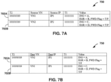
- FIGS. 7A-7B are block diagrams of an example source index table 700 and an example destination index table 750 for analytics database 35 for storing session-based traffic statistics in accordance with the techniques of the disclosure.
- source index table 700 and destination index table 750 permit queries to obtain session information at various points in time without no loss of information with respect to the individual flows described by each session.
- source index table 700 describes a plurality of entries after receiving a first session record 702A and a second session record 702B from a VR agent 36.
- destination index table 700 describes a plurality of entries parallel to that of source index table 700 after receiving the first session record 702A and the second session record 702B.
- FIG. 8 is an example flowchart illustrating an operation for querying analytics database 35 for session-based traffic statistics records.
- FIG. 8 is described with respect to the example system of FIG. 3 and the example source index table 700 and example destination index table 750 of FIGS. 7A-7B .
- source index table 700 and destination index table 750 Upon querying source index table 700 and destination index table 750, the query specifies a direction of traffic (e.g., an ingress or an egress).
- a direction of traffic e.g., an ingress or an egress.
- FIG. 8 illustrates how the querying logic of analytics database 35 operates and provides information on which of source index table 700 and destination index table 750 to query and which field to use while querying. Because the techniques described herein modify the number of flow index tables within analytics database 35, modified lookup queries to analytics database 35 are described.
- analytics database 35 receives a query for session-based traffic statistics, wherein the query includes one of a Source Virtual Network (SVN) or a Destination Virtual Network (DVN), one of a Source IP Address (SIP) and a Destination IP Address (DIP), and one direction of an Ingress and an Egress (802).
- Analytics database 35 determines whether the query specifies an SVN and an Ingress direction (804). If the query specifies an SVN and an Ingress direction (e.g., "YES" block of 804), analytics database 35 applies the query as an ingress key of the source index table 700 (806) and returns the session-based traffic statistics corresponding to the query.
- analytics database 35 determines whether the query specifies an SVN and an Ingress direction (808). If the query specifies an SVN and an Egress direction (e.g., "YES" block of 808), analytics database 35 applies the query as an egress key of the source index table 700 (810) and returns the session-based traffic statistics corresponding to the query.
- analytics database 35 determines whether the query specifies a DVN and an Ingress direction (812). If the query specifies a DVN and an Ingress direction (e.g., "YES" block of 812), the analytics database 35 applies the query as an ingress key of the destination index table 750 (814) and returns the session-based traffic statistics corresponding to the query.
- analytics database 35 swaps the key and applies the query as an egress key of the source index table 700 (816) and returns the session-based traffic statistics corresponding to the query.
- a query may return flow-based traffic statistics information.
- any WHERE query which does not have an OR unit with an SVN or a DVN is handled differently because such a query requires fetching all the SVN or DVN and is not supported by Cassandra Query Language (CQL).
- CQL Cassandra Query Language
- queries in which there are OR units not conditioned on SVN or DVN may require a different path.
- Such queries are referred to herein as '* query processing.' If a query is identified as a '* query', only a single database lookup is necessary. The different conditions specified in the WHERE query are evaluated against the results fetched. This eliminates the repeated reads that otherwise may be involved. Examples of such queries are described below:
- a query may be determined to be a '* query' after a QueryPrepare step.
- the QueryPrepare step checks for syntactic correctness of a query. Changes may be made to the QueryPrepare step to determine whether a query is a '*query'.
- the system Upon identifying the query as a '*query', the system creates a pipeline that performs the query against the source index table or destination index table and stores the results of the query for each chunk.
Landscapes
- Engineering & Computer Science (AREA)
- Computer Networks & Wireless Communication (AREA)
- Signal Processing (AREA)
- Mathematical Physics (AREA)
- Physics & Mathematics (AREA)
- Algebra (AREA)
- General Physics & Mathematics (AREA)
- Mathematical Analysis (AREA)
- Mathematical Optimization (AREA)
- Probability & Statistics with Applications (AREA)
- Pure & Applied Mathematics (AREA)
- Computer Security & Cryptography (AREA)
- Environmental & Geological Engineering (AREA)
- Data Exchanges In Wide-Area Networks (AREA)
Claims (15)
- Verfahren, das Folgendes umfasst:
Verarbeiten, durch einen virtuellen Router (42), der auf einem Prozessor eines Servers (26) innerhalb eines Cloud-Datenzentrums (10) ausgeführt wird, mehrerer Verkehrsflüsse für eine oder mehrere virtuelle Maschinen (48), die auf dem Server innerhalb des Cloud-Datenzentrums ausgeführt werden, um Verkehrsflussstatistiken für die mehreren Verkehrsflüsse zu erzeugen, wobei die mehreren Verkehrsflüsse Folgendes beinhalten:mehrere eingehende Verkehrsflüsse (50A), die von der einen oder den mehreren virtuellen Maschinen stammen und für ein Netz des Cloud-Datenzentrums bestimmt sind; und mehrere ausgehende Verkehrsflüsse (50B), die von dem Netz des Cloud-Datenzentrums stammen und für die eine oder die mehreren virtuellen Maschinen bestimmt sind;Verarbeiten der Verkehrsflussstatistiken, um Paare der mehreren eingehenden Verkehrsflüsse und der mehreren ausgehenden Verkehrsflüsse zu identifizieren, die einer gemeinsamen Kommunikationssitzung entsprechen, für die eine oder die mehreren virtuellen Maschinen;Erzeugen, für jedes der identifizierten Paare der mehreren eingehenden Verkehrsflüsse und der mehreren ausgehenden Verkehrsflüsse, von Sitzungsaufzeichnungen, die Verkehrssitzungsstatistiken für die gemeinsame Kommunikationssitzung umfassen, die dem jeweiligen einen der mehreren eingehenden Verkehrsflüssen und dem jeweiligen einen der mehreren ausgehenden Verkehrsflüssen des Paars entsprechen; undHochladen der Sitzungsaufzeichnungen auf einen Verkehrskollektor (34) für das Netz des Cloud-Datenzentrums. - Verfahren nach Anspruch 1, wobei das Verarbeiten der Verkehrsflussstatistiken, um Paare der mehreren eingehenden Verkehrsflüsse und der mehreren ausgehenden Verkehrsflüsse zu identifizieren, die einer gemeinsamen Kommunikationssitzung entsprechen, für die eine oder die mehreren virtuellen Maschinen Folgendes umfasst:Kommunizieren der Verkehrsflussstatistiken an einen virtuellen Agenten (36), der in einem Benutzerraum des Servers ausgeführt wird; undVerarbeiten der Verkehrsflussstatistiken mit dem virtuellen Agenten.
- Verfahren nach einem der Ansprüche 1-2, wobei das Hochladen der Sitzungsaufzeichnungen auf den Verkehrskollektor für das Netz des Cloud-Datenzentrums Hochladen der Sitzungsaufzeichnungen auf den Verkehrskollektor einer Software-Defined-Networking- bzw. SDN-Steuerung (32) für das Netz des Cloud-Datenzentrums umfasst.
- Verfahren nach einem der Ansprüche 1-3,wobei die Verkehrsflussstatistiken eine Anzahl eingehender Bytes für jeden der mehreren eingehenden Verkehrsflüsse und eine Anzahl ausgehender Bytes für jeden der mehreren ausgehenden Verkehrsflüsse beinhalten, undjede der Verkehrssitzungsstatistiken für die gemeinsame Kommunikationssitzung, die dem jeweiligen einen der mehreren eingehenden Verkehrsflüsse und dem einen der mehreren ausgehenden Verkehrsflüsse des Paars entspricht, die Anzahl eingehender Bytes für den jeweiligen einen der mehreren eingehenden Verkehrsflüsse und die Anzahl ausgehender Bytes für den jeweiligen einen der mehreren ausgehenden Verkehrsflüsse beinhaltet.
- Verfahren nach einem der Ansprüche 1-4,wobei, für jeden der mehreren eingehenden Verkehrsflüsse und mehreren ausgehenden Verkehrsflüsse, die einer gemeinsamen Kommunikationssitzung entsprechen, die Verkehrssitzungsstatistiken ein Protokoll, eine Quellenadresse, eine Zieladresse, einen Quellenport und einen Zielport des Verkehrsflusses beinhalten, undwobei das Verarbeiten der Verkehrsflussstatistiken, um Paare der mehreren eingehenden Verkehrsflüsse und der mehreren ausgehenden Verkehrsflüsse zu identifizieren, die einer gemeinsamen Kommunikationssitzung entsprechen, für die eine oder die mehreren virtuellen Maschinen Vergleichen des Protokolls, der Quellenadresse, der Zieladresse, des Quellenports und des Zielports des jeweiligen einen der mehreren eingehenden Verkehrsflüsse des Paars mit dem Protokoll, der Quellenadresse, der Zieladresse, dem Quellenport und dem Zielport des jeweiligen einen der mehreren ausgehenden Verkehrsflüsse des Paars umfasst.
- Verfahren nach Anspruch 5, wobei das Vergleichen des Protokolls, der Quellenadresse, der Zieladresse, des Quellenports und des Zielports des jeweiligen einen der mehreren eingehenden Verkehrsflüsse des Paars mit dem Protokoll, der Quellenadresse, der Zieladresse, dem Quellenport und dem Zielport des jeweiligen einen der mehreren ausgehenden Verkehrsflüsse des Paars Bestimmen davon umfasst, ob ein eingehender Verkehrsfluss der mehreren eingehenden Verkehrsflüsse und ein ausgehender Verkehrsfluss der mehreren ausgehenden Verkehrsflüsse ein Protokoll teilen, ob eine Quellenadresse und ein Quellenport des eingehenden Flusses gleich einer Zieladresse und einem Zielport des ausgehenden Flusses sind, und ob eine Zieladresse und ein Zielport des eingehenden Flusses gleich einer Quellenadresse und einem Zielport des ausgehenden Flusses sind.
- Verfahren nach Anspruch 1, das ferner Folgendes umfasst:Empfangen, durch den Verkehrskollektor, der Sitzungsaufzeichnungen, die Verkehrssitzungsstatistiken für gemeinsame Kommunikationssitzungen, die den Paaren von Verkehrsflüssen entsprechen, und für die eine oder die mehreren virtuellen Maschinen umfassen; undSpeichern, durch den Verkehrskollektor, der Sitzungsaufzeichnungen in einer Analysedatenbank.
- Verfahren nach Anspruch 7, wobei die Analysedatenbank eine Quellenindextabelle (500) und eine Zielindextabelle (600) umfasst, und wobei das Speichern der Sitzungsaufzeichnungen in der Analysedatenbank für jede der Sitzungsaufzeichnungen Folgendes umfasst:Schreiben, durch den Verkehrskollektor, der Verkehrssitzungsstatistiken für jedes Paar von Verkehrsflüssen in die Quellenindextabelle; undSchreiben, durch den Verkehrskollektor, der Verkehrssitzungsstatistiken für jedes Paar von Verkehrsflüssen in die Zielindextabelle.
- Verfahren nach Anspruch 8, wobei, für jeden eingehenden Verkehrsfluss oder ausgehenden Verkehrsfluss der Sitzungsaufzeichnungen, die Verkehrssitzungsstatistiken ein Protokoll, eine Quellenadresse, eine Zieladresse, einen Quellenport und einen Zielport des Verkehrsflusses beinhalten.
- Verfahren nach Anspruch 9, wobei das Schreiben der Verkehrssitzungsstatistiken für jede gemeinsame Kommunikationssitzung in die Quellenindextabelle Schreiben, für jedes Paar von Verkehrsflüssen, die der gemeinsamen Kommunikationssitzung entsprechen, des Protokolls, der Quellenadresse und des Quellenports für den jeweiligen eingehenden Verkehrsfluss des Paars und des Protokolls, der Quellenadresse und des Quellenports für den jeweiligen ausgehenden Verkehrsfluss des Paars in die Quellenindextabelle umfasst, und
wobei das Schreiben der Verkehrssitzungsstatistiken für jede gemeinsame Kommunikationssitzung in die Zielindextabelle Schreiben, für jedes Paar von Verkehrsflüssen, die der gemeinsamen Kommunikationssitzung entsprechen, des Protokolls, der Zieladresse und des Zielports für den jeweiligen eingehenden Verkehrsfluss des Paars und des Protokolls, der Zieladresse und des Zielports für den jeweiligen ausgehenden Verkehrsfluss des Paars in die Zielindextabelle umfasst. - Verfahren nach einem der Ansprüche 7-10, wobei das Speichern der Sitzungsaufzeichnungen in der Analysedatenbank, für jede der Sitzungsaufzeichnungen, Speichern der Sitzungsaufzeichnungen in der Analysedatenbank in nicht mehr als zwei Schreibvorgängen umfasst.
- Verfahren nach einem der Ansprüche 7 bis 11, das ferner Folgendes umfasst:Empfangen, durch die Analysedatenbank, einer Anfrage nach Verkehrssitzungsstatistiken für ein erstes Paar von Verkehrsflüssen der Paare von Verkehrsflüssen; undBereitstellen, als Reaktion auf die Anfrage, der Verkehrssitzungsstatistiken für das erste Paar von Verkehrsflüssen der Paare von Verkehrsflüssen.
- Verfahren nach Anspruch 12, wobei die Anfrage ein virtuelles Netz, eine IP-Adresse und eine Richtung umfasst und wobei das virtuelle Netz der Anfrage eines von einem virtuellen Quellennetz, SVN (Source Virtual Network), der einen oder mehreren virtuellen Maschinen oder einem virtuellen Zielnetz (DVN: Destination Virtual Network) des Netzes des Cloud-Datenzentrums ist,wobei die IP-Adresse eine einer Quellen-IP-Adresse, SIP (Source IP Address), der einen oder mehreren virtuellen Maschinen oder eine Ziel-IP-Adresse, DIP (Destination IP Address), des Netzes des Cloud-Datenzentrums ist, undwobei die Richtung eine eines Eingangs der einen oder mehreren virtuellen Maschinen oder eines Ausgangs des Netzes des Cloud-Datenzentrums ist.
- Weiterleitungskomponente, die auf einem Prozessor eines Servers innerhalb eines Cloud-Datenzentrums ausgeführt wird, konfiguriert zum Durchführen eines der Verfahren nach Ansprüchen 1-6.
- System, das Folgendes umfasst:eine Weiterleitungskomponente, die auf einem Prozessor eines Servers innerhalb eines Cloud-Datenzentrums ausgeführt wird, konfiguriert zum Durchführen eines der Verfahren nach Ansprüchen 1-6; undeinen Verkehrskollektor für ein Netz des Cloud-Datenzentrums, der zum Durchführen eines der Verfahren nach Ansprüchen 7-13 konfiguriert ist.
Applications Claiming Priority (1)
| Application Number | Priority Date | Filing Date | Title |
|---|---|---|---|
| US15/476,136 US10291497B2 (en) | 2017-03-31 | 2017-03-31 | Session-based traffic statistics logging for virtual routers |
Publications (3)
| Publication Number | Publication Date |
|---|---|
| EP3382959A2 EP3382959A2 (de) | 2018-10-03 |
| EP3382959A3 EP3382959A3 (de) | 2018-10-10 |
| EP3382959B1 true EP3382959B1 (de) | 2025-03-05 |
Family
ID=61132234
Family Applications (1)
| Application Number | Title | Priority Date | Filing Date |
|---|---|---|---|
| EP18154544.3A Active EP3382959B1 (de) | 2017-03-31 | 2018-01-31 | Protokollierung sitzungsbasierter datenverkehrsstatistiken für virtuelle router |
Country Status (3)
| Country | Link |
|---|---|
| US (1) | US10291497B2 (de) |
| EP (1) | EP3382959B1 (de) |
| CN (1) | CN108696402B (de) |
Families Citing this family (44)
| Publication number | Priority date | Publication date | Assignee | Title |
|---|---|---|---|---|
| US10601661B2 (en) | 2015-06-22 | 2020-03-24 | Arista Networks, Inc. | Tracking state of components within a network element |
| US10498810B2 (en) * | 2017-05-04 | 2019-12-03 | Amazon Technologies, Inc. | Coordinating inter-region operations in provider network environments |
| US11336572B2 (en) | 2017-05-12 | 2022-05-17 | Nicira, Inc. | Dynamic chain of service functions for processing network traffic in a virtual computing environment |
| US20180331963A1 (en) * | 2017-05-12 | 2018-11-15 | Guavus, Inc. | Determining data flows to an ingress router with data flows received at an egress router |
| US11102186B2 (en) * | 2018-04-26 | 2021-08-24 | Vmware, Inc. | Packet capture in software-defined networking (SDN) environments |
| US11159389B1 (en) | 2018-06-28 | 2021-10-26 | Juniper Networks, Inc. | Inter-application workload network traffic monitoring and visualization |
| US10999251B2 (en) | 2018-09-28 | 2021-05-04 | Juniper Networks, Inc. | Intent-based policy generation for virtual networks |
| US10757009B2 (en) | 2018-11-20 | 2020-08-25 | Amazon Technologies, Inc. | Global-scale connectivity using scalable virtual traffic hubs |
| US11258661B2 (en) * | 2019-04-26 | 2022-02-22 | Juniper Networks, Inc. | Initializing server configurations in a data center |
| US11153194B2 (en) | 2019-04-26 | 2021-10-19 | Juniper Networks, Inc. | Control plane isolation for software defined network routing services |
| US11997011B2 (en) | 2019-04-26 | 2024-05-28 | Juniper Networks, Inc. | Virtual port group |
| US11095504B2 (en) * | 2019-04-26 | 2021-08-17 | Juniper Networks, Inc. | Initializing network device and server configurations in a data center |
| US11431654B2 (en) * | 2019-06-17 | 2022-08-30 | Cyxtera Data Centers, Inc. | Network service integration into a network fabric of a data center |
| US10996938B2 (en) | 2019-07-15 | 2021-05-04 | Juniper Networks, Inc. | Automated selection of software images for network devices |
| US10924419B1 (en) | 2019-08-15 | 2021-02-16 | Juniper Networks, Inc. | Underlay-overlay correlation |
| US11888738B2 (en) * | 2019-08-15 | 2024-01-30 | Juniper Networks, Inc. | System and method for determining a data flow path in an overlay network |
| US11316738B2 (en) | 2019-08-19 | 2022-04-26 | Juniper Networks, Inc. | Vendor agnostic profile-based modeling of service access endpoints in a multitenant environment |
| US11240144B2 (en) * | 2019-09-30 | 2022-02-01 | Juniper Networks, Inc. | Assisted replication in software defined network |
| US11595393B2 (en) | 2020-03-31 | 2023-02-28 | Juniper Networks, Inc. | Role-based access control policy auto generation |
| EP4136810A1 (de) * | 2020-04-16 | 2023-02-22 | Juniper Networks, Inc. | Mandantenbasierte abbildung für virtuelles routing und weiterleiten |
| KR102322454B1 (ko) * | 2020-04-28 | 2021-11-05 | 고려대학교 산학협력단 | 프로그래밍 가능한 네트워크 가상화에서의 모니터링 방법 및 시스템 |
| CN111698168B (zh) * | 2020-05-20 | 2022-06-28 | 北京吉安金芯信息技术有限公司 | 消息处理方法、装置、存储介质及处理器 |
| US11469998B2 (en) | 2020-05-27 | 2022-10-11 | Juniper Networks, Inc. | Data center tenant network isolation using logical router interconnects for virtual network route leaking |
| US10999142B1 (en) | 2020-06-30 | 2021-05-04 | Juniper Networks, Inc. | Correlation of virtual network traffic across bare metal servers |
| US11444855B2 (en) | 2020-07-07 | 2022-09-13 | Juniper Networks, Inc. | System and method for determining a data flow path in an overlay network |
| US12542739B2 (en) | 2020-07-20 | 2026-02-03 | Juniper Networks, Inc. | Generating route distinguishers for virtual private network addresses based on physical hardware addresses |
| US12160366B2 (en) | 2021-03-30 | 2024-12-03 | Amazon Technologies, Inc. | Multi-tenant offloaded protocol processing for virtual routers |
| US11824773B2 (en) * | 2021-03-30 | 2023-11-21 | Amazon Technologies, Inc. | Dynamic routing for peered virtual routers |
| US11394663B1 (en) | 2021-03-31 | 2022-07-19 | Juniper Networks, Inc. | Selective packet processing including a run-to-completion packet processing data plane |
| CN113595936B (zh) * | 2021-08-03 | 2022-09-20 | 中国电信股份有限公司 | 流量监管方法、网关设备和存储介质 |
| CN113839831B (zh) * | 2021-08-27 | 2023-04-18 | 深圳市风云实业有限公司 | 一种流量采样装置 |
| US12074884B2 (en) | 2021-10-04 | 2024-08-27 | Juniper Networks, Inc. | Role-based access control autogeneration in a cloud native software-defined network architecture |
| CN119906631A (zh) | 2021-10-04 | 2025-04-29 | 瞻博网络公司 | 用于连续部署的网络策略生成 |
| US11870642B2 (en) | 2021-10-04 | 2024-01-09 | Juniper Networks, Inc. | Network policy generation for continuous deployment |
| CN115996183A (zh) * | 2021-10-15 | 2023-04-21 | 中国联合网络通信集团有限公司 | 流量确定方法及设备 |
| US11711279B2 (en) * | 2021-10-26 | 2023-07-25 | Juniper Networks, Inc. | Application records using session information |
| US12218839B1 (en) * | 2021-11-01 | 2025-02-04 | Juniper Networks, Inc. | Service function chaining with session-based routing |
| CA3252710A1 (en) * | 2022-05-09 | 2023-11-16 | Centurylink Intellectual Property Llc | DENIAL OF SERVICE ATTACK MITIGATION SYSTEMS AND METHODS |
| US12483499B2 (en) | 2023-03-27 | 2025-11-25 | Amazon Technologies, Inc. | Custom configuration of cloud-based multi-network-segment gateways |
| US12021743B1 (en) | 2023-03-27 | 2024-06-25 | Amazon Technologies, Inc. | Software-defined multi-network-segment gateways for scalable routing of traffic between customer-premise network segments and cloud-based virtual networks |
| US12489707B1 (en) | 2023-06-21 | 2025-12-02 | Amazon Technologies, Inc. | Modification of routing and forwarding information for cloud network traffic using customer-specified rules |
| CN116708041B (zh) * | 2023-08-07 | 2023-11-03 | 烽台科技(北京)有限公司 | 伪装代理方法、装置、设备及介质 |
| CN119544447A (zh) * | 2024-11-13 | 2025-02-28 | 中国建设银行股份有限公司 | 一种数据处理方法、装置和系统 |
| CN120658527B (zh) * | 2025-08-15 | 2025-10-17 | 北京浩瀚深度信息技术股份有限公司 | 对基于tcp协议的通用境外vpn代理流量识别方法及其系统 |
Citations (3)
| Publication number | Priority date | Publication date | Assignee | Title |
|---|---|---|---|---|
| US20090238088A1 (en) * | 2008-03-19 | 2009-09-24 | Oki Electric Industry Co., Ltd. | Network traffic analyzing device, network traffic analyzing method and network traffic analyzing system |
| US20160359872A1 (en) * | 2015-06-05 | 2016-12-08 | Cisco Technology, Inc. | System for monitoring and managing datacenters |
| EP3113424A2 (de) * | 2012-06-06 | 2017-01-04 | Juniper Networks, Inc. | Bestimmung des physikalischen pfads für paketströme in einem virtuellen netzwerk |
Family Cites Families (14)
| Publication number | Priority date | Publication date | Assignee | Title |
|---|---|---|---|---|
| US7054901B2 (en) * | 2001-05-31 | 2006-05-30 | Juniper Networks, Inc. | Network management interface with selective rendering of output |
| US8331234B1 (en) | 2004-09-08 | 2012-12-11 | Q1 Labs Inc. | Network data flow collection and processing |
| US7508764B2 (en) * | 2005-09-12 | 2009-03-24 | Zeugma Systems Inc. | Packet flow bifurcation and analysis |
| US9634851B2 (en) * | 2009-04-20 | 2017-04-25 | Ca, Inc. | System, method, and computer readable medium for measuring network latency from flow records |
| US9898317B2 (en) * | 2012-06-06 | 2018-02-20 | Juniper Networks, Inc. | Physical path determination for virtual network packet flows |
| US9014034B2 (en) * | 2012-09-21 | 2015-04-21 | Cisco Technology, Inc. | Efficient network traffic analysis using a hierarchical key combination data structure |
| US9438488B2 (en) * | 2012-11-09 | 2016-09-06 | Citrix Systems, Inc. | Systems and methods for appflow for datastream |
| US9569232B1 (en) * | 2013-02-19 | 2017-02-14 | Amazon Technologies, Inc. | Network traffic data in virtualized environments |
| US9755960B2 (en) * | 2013-09-30 | 2017-09-05 | Juniper Networks, Inc. | Session-aware service chaining within computer networks |
| US9413634B2 (en) * | 2014-01-10 | 2016-08-09 | Juniper Networks, Inc. | Dynamic end-to-end network path setup across multiple network layers with network service chaining |
| US9787559B1 (en) * | 2014-03-28 | 2017-10-10 | Juniper Networks, Inc. | End-to-end monitoring of overlay networks providing virtualized network services |
| US10164846B2 (en) * | 2014-03-28 | 2018-12-25 | Fortinet, Inc. | Network flow analysis |
| US9641435B1 (en) | 2014-03-28 | 2017-05-02 | Juniper Neworks, Inc. | Packet segmentation offload for virtual networks |
| US20160050132A1 (en) * | 2014-08-18 | 2016-02-18 | Telefonaktiebolaget L M Ericsson (Publ) | Method and system to dynamically collect statistics of traffic flows in a software-defined networking (sdn) system |
-
2017
- 2017-03-31 US US15/476,136 patent/US10291497B2/en active Active
-
2018
- 2018-01-31 EP EP18154544.3A patent/EP3382959B1/de active Active
- 2018-02-28 CN CN201810167632.5A patent/CN108696402B/zh active Active
Patent Citations (4)
| Publication number | Priority date | Publication date | Assignee | Title |
|---|---|---|---|---|
| US20090238088A1 (en) * | 2008-03-19 | 2009-09-24 | Oki Electric Industry Co., Ltd. | Network traffic analyzing device, network traffic analyzing method and network traffic analyzing system |
| EP3113424A2 (de) * | 2012-06-06 | 2017-01-04 | Juniper Networks, Inc. | Bestimmung des physikalischen pfads für paketströme in einem virtuellen netzwerk |
| US20160359872A1 (en) * | 2015-06-05 | 2016-12-08 | Cisco Technology, Inc. | System for monitoring and managing datacenters |
| US10142353B2 (en) * | 2015-06-05 | 2018-11-27 | Cisco Technology, Inc. | System for monitoring and managing datacenters |
Also Published As
| Publication number | Publication date |
|---|---|
| EP3382959A2 (de) | 2018-10-03 |
| CN108696402A (zh) | 2018-10-23 |
| CN108696402B (zh) | 2022-04-19 |
| EP3382959A3 (de) | 2018-10-10 |
| US10291497B2 (en) | 2019-05-14 |
| US20180287905A1 (en) | 2018-10-04 |
Similar Documents
| Publication | Publication Date | Title |
|---|---|---|
| EP3382959B1 (de) | Protokollierung sitzungsbasierter datenverkehrsstatistiken für virtuelle router | |
| CN111614605B (zh) | 用于配置防火墙的方法、安全管理系统和计算机可读介质 | |
| EP4024787B1 (de) | Gemeinsame nutzung von routen unter verwendung eines in-speicher-datenspeichers in einem verteilten netzwerksystem | |
| US10565001B2 (en) | Distributed virtual network controller | |
| EP2859694B1 (de) | Physikalische pfadbestimmung für paketströme in einem virtuellen netzwerk | |
| US10742607B2 (en) | Application-aware firewall policy enforcement by data center controller | |
| US9596159B2 (en) | Finding latency through a physical network in a virtualized network | |
| US11652727B2 (en) | Service chaining with physical network functions and virtualized network functions | |
| US12289234B1 (en) | Logical fabric overlays |
Legal Events
| Date | Code | Title | Description |
|---|---|---|---|
| PUAI | Public reference made under article 153(3) epc to a published international application that has entered the european phase |
Free format text: ORIGINAL CODE: 0009012 |
|
| STAA | Information on the status of an ep patent application or granted ep patent |
Free format text: STATUS: THE APPLICATION HAS BEEN PUBLISHED |
|
| PUAL | Search report despatched |
Free format text: ORIGINAL CODE: 0009013 |
|
| AK | Designated contracting states |
Kind code of ref document: A2 Designated state(s): AL AT BE BG CH CY CZ DE DK EE ES FI FR GB GR HR HU IE IS IT LI LT LU LV MC MK MT NL NO PL PT RO RS SE SI SK SM TR |
|
| AX | Request for extension of the european patent |
Extension state: BA ME |
|
| AK | Designated contracting states |
Kind code of ref document: A3 Designated state(s): AL AT BE BG CH CY CZ DE DK EE ES FI FR GB GR HR HU IE IS IT LI LT LU LV MC MK MT NL NO PL PT RO RS SE SI SK SM TR |
|
| AX | Request for extension of the european patent |
Extension state: BA ME |
|
| RIC1 | Information provided on ipc code assigned before grant |
Ipc: H04L 12/26 20060101ALI20180906BHEP Ipc: H04L 12/851 20130101AFI20180906BHEP |
|
| STAA | Information on the status of an ep patent application or granted ep patent |
Free format text: STATUS: REQUEST FOR EXAMINATION WAS MADE |
|
| 17P | Request for examination filed |
Effective date: 20190410 |
|
| RBV | Designated contracting states (corrected) |
Designated state(s): AL AT BE BG CH CY CZ DE DK EE ES FI FR GB GR HR HU IE IS IT LI LT LU LV MC MK MT NL NO PL PT RO RS SE SI SK SM TR |
|
| STAA | Information on the status of an ep patent application or granted ep patent |
Free format text: STATUS: EXAMINATION IS IN PROGRESS |
|
| 17Q | First examination report despatched |
Effective date: 20200714 |
|
| REG | Reference to a national code |
Ref country code: DE Ref legal event code: R079 Free format text: PREVIOUS MAIN CLASS: H04L0012851000 Ipc: H04L0047248300 Ref country code: DE Ref legal event code: R079 Ref document number: 602018079757 Country of ref document: DE Free format text: PREVIOUS MAIN CLASS: H04L0012851000 Ipc: H04L0047248300 |
|
| GRAP | Despatch of communication of intention to grant a patent |
Free format text: ORIGINAL CODE: EPIDOSNIGR1 |
|
| STAA | Information on the status of an ep patent application or granted ep patent |
Free format text: STATUS: GRANT OF PATENT IS INTENDED |
|
| RIC1 | Information provided on ipc code assigned before grant |
Ipc: H04L 43/20 20220101ALI20240911BHEP Ipc: H04L 41/40 20220101ALI20240911BHEP Ipc: H04L 45/745 20220101ALI20240911BHEP Ipc: H04L 43/0876 20220101ALI20240911BHEP Ipc: H04L 43/04 20220101ALI20240911BHEP Ipc: H04L 41/142 20220101ALI20240911BHEP Ipc: H04L 41/046 20220101ALI20240911BHEP Ipc: H04L 43/062 20220101ALI20240911BHEP Ipc: H04L 47/2441 20220101ALI20240911BHEP Ipc: H04L 47/2483 20220101AFI20240911BHEP |
|
| INTG | Intention to grant announced |
Effective date: 20240923 |
|
| GRAS | Grant fee paid |
Free format text: ORIGINAL CODE: EPIDOSNIGR3 |
|
| GRAA | (expected) grant |
Free format text: ORIGINAL CODE: 0009210 |
|
| STAA | Information on the status of an ep patent application or granted ep patent |
Free format text: STATUS: THE PATENT HAS BEEN GRANTED |
|
| AK | Designated contracting states |
Kind code of ref document: B1 Designated state(s): AL AT BE BG CH CY CZ DE DK EE ES FI FR GB GR HR HU IE IS IT LI LT LU LV MC MK MT NL NO PL PT RO RS SE SI SK SM TR |
|
| REG | Reference to a national code |
Ref country code: GB Ref legal event code: FG4D |
|
| REG | Reference to a national code |
Ref country code: CH Ref legal event code: EP |
|
| REG | Reference to a national code |
Ref country code: IE Ref legal event code: FG4D |
|
| REG | Reference to a national code |
Ref country code: DE Ref legal event code: R096 Ref document number: 602018079757 Country of ref document: DE |
|
| P01 | Opt-out of the competence of the unified patent court (upc) registered |
Free format text: CASE NUMBER: APP_10295/2025 Effective date: 20250228 |
|
| PG25 | Lapsed in a contracting state [announced via postgrant information from national office to epo] |
Ref country code: RS Free format text: LAPSE BECAUSE OF FAILURE TO SUBMIT A TRANSLATION OF THE DESCRIPTION OR TO PAY THE FEE WITHIN THE PRESCRIBED TIME-LIMIT Effective date: 20250605 |
|
| PG25 | Lapsed in a contracting state [announced via postgrant information from national office to epo] |
Ref country code: FI Free format text: LAPSE BECAUSE OF FAILURE TO SUBMIT A TRANSLATION OF THE DESCRIPTION OR TO PAY THE FEE WITHIN THE PRESCRIBED TIME-LIMIT Effective date: 20250305 |
|
| REG | Reference to a national code |
Ref country code: NL Ref legal event code: MP Effective date: 20250305 |
|
| PG25 | Lapsed in a contracting state [announced via postgrant information from national office to epo] |
Ref country code: ES Free format text: LAPSE BECAUSE OF FAILURE TO SUBMIT A TRANSLATION OF THE DESCRIPTION OR TO PAY THE FEE WITHIN THE PRESCRIBED TIME-LIMIT Effective date: 20250305 |
|
| REG | Reference to a national code |
Ref country code: LT Ref legal event code: MG9D |
|
| PG25 | Lapsed in a contracting state [announced via postgrant information from national office to epo] |
Ref country code: NO Free format text: LAPSE BECAUSE OF FAILURE TO SUBMIT A TRANSLATION OF THE DESCRIPTION OR TO PAY THE FEE WITHIN THE PRESCRIBED TIME-LIMIT Effective date: 20250605 |
|
| PG25 | Lapsed in a contracting state [announced via postgrant information from national office to epo] |
Ref country code: HR Free format text: LAPSE BECAUSE OF FAILURE TO SUBMIT A TRANSLATION OF THE DESCRIPTION OR TO PAY THE FEE WITHIN THE PRESCRIBED TIME-LIMIT Effective date: 20250305 |
|
| PG25 | Lapsed in a contracting state [announced via postgrant information from national office to epo] |
Ref country code: LV Free format text: LAPSE BECAUSE OF FAILURE TO SUBMIT A TRANSLATION OF THE DESCRIPTION OR TO PAY THE FEE WITHIN THE PRESCRIBED TIME-LIMIT Effective date: 20250305 |
|
| PG25 | Lapsed in a contracting state [announced via postgrant information from national office to epo] |
Ref country code: GR Free format text: LAPSE BECAUSE OF FAILURE TO SUBMIT A TRANSLATION OF THE DESCRIPTION OR TO PAY THE FEE WITHIN THE PRESCRIBED TIME-LIMIT Effective date: 20250606 Ref country code: BG Free format text: LAPSE BECAUSE OF FAILURE TO SUBMIT A TRANSLATION OF THE DESCRIPTION OR TO PAY THE FEE WITHIN THE PRESCRIBED TIME-LIMIT Effective date: 20250305 |
|
| REG | Reference to a national code |
Ref country code: AT Ref legal event code: MK05 Ref document number: 1773995 Country of ref document: AT Kind code of ref document: T Effective date: 20250305 |
|
| PG25 | Lapsed in a contracting state [announced via postgrant information from national office to epo] |
Ref country code: NL Free format text: LAPSE BECAUSE OF FAILURE TO SUBMIT A TRANSLATION OF THE DESCRIPTION OR TO PAY THE FEE WITHIN THE PRESCRIBED TIME-LIMIT Effective date: 20250305 |
|
| PG25 | Lapsed in a contracting state [announced via postgrant information from national office to epo] |
Ref country code: SE Free format text: LAPSE BECAUSE OF FAILURE TO SUBMIT A TRANSLATION OF THE DESCRIPTION OR TO PAY THE FEE WITHIN THE PRESCRIBED TIME-LIMIT Effective date: 20250305 |
|
| PG25 | Lapsed in a contracting state [announced via postgrant information from national office to epo] |
Ref country code: SM Free format text: LAPSE BECAUSE OF FAILURE TO SUBMIT A TRANSLATION OF THE DESCRIPTION OR TO PAY THE FEE WITHIN THE PRESCRIBED TIME-LIMIT Effective date: 20250305 |
|
| PG25 | Lapsed in a contracting state [announced via postgrant information from national office to epo] |
Ref country code: PT Free format text: LAPSE BECAUSE OF FAILURE TO SUBMIT A TRANSLATION OF THE DESCRIPTION OR TO PAY THE FEE WITHIN THE PRESCRIBED TIME-LIMIT Effective date: 20250707 |
|
| PG25 | Lapsed in a contracting state [announced via postgrant information from national office to epo] |
Ref country code: IT Free format text: LAPSE BECAUSE OF FAILURE TO SUBMIT A TRANSLATION OF THE DESCRIPTION OR TO PAY THE FEE WITHIN THE PRESCRIBED TIME-LIMIT Effective date: 20250305 Ref country code: PL Free format text: LAPSE BECAUSE OF FAILURE TO SUBMIT A TRANSLATION OF THE DESCRIPTION OR TO PAY THE FEE WITHIN THE PRESCRIBED TIME-LIMIT Effective date: 20250305 |
|
| PG25 | Lapsed in a contracting state [announced via postgrant information from national office to epo] |
Ref country code: AT Free format text: LAPSE BECAUSE OF FAILURE TO SUBMIT A TRANSLATION OF THE DESCRIPTION OR TO PAY THE FEE WITHIN THE PRESCRIBED TIME-LIMIT Effective date: 20250305 |
|
| PG25 | Lapsed in a contracting state [announced via postgrant information from national office to epo] |
Ref country code: CZ Free format text: LAPSE BECAUSE OF FAILURE TO SUBMIT A TRANSLATION OF THE DESCRIPTION OR TO PAY THE FEE WITHIN THE PRESCRIBED TIME-LIMIT Effective date: 20250305 Ref country code: EE Free format text: LAPSE BECAUSE OF FAILURE TO SUBMIT A TRANSLATION OF THE DESCRIPTION OR TO PAY THE FEE WITHIN THE PRESCRIBED TIME-LIMIT Effective date: 20250305 |
|
| PG25 | Lapsed in a contracting state [announced via postgrant information from national office to epo] |
Ref country code: RO Free format text: LAPSE BECAUSE OF FAILURE TO SUBMIT A TRANSLATION OF THE DESCRIPTION OR TO PAY THE FEE WITHIN THE PRESCRIBED TIME-LIMIT Effective date: 20250305 |
|
| PG25 | Lapsed in a contracting state [announced via postgrant information from national office to epo] |
Ref country code: SK Free format text: LAPSE BECAUSE OF FAILURE TO SUBMIT A TRANSLATION OF THE DESCRIPTION OR TO PAY THE FEE WITHIN THE PRESCRIBED TIME-LIMIT Effective date: 20250305 |
|
| PG25 | Lapsed in a contracting state [announced via postgrant information from national office to epo] |
Ref country code: IS Free format text: LAPSE BECAUSE OF FAILURE TO SUBMIT A TRANSLATION OF THE DESCRIPTION OR TO PAY THE FEE WITHIN THE PRESCRIBED TIME-LIMIT Effective date: 20250705 |
|
| REG | Reference to a national code |
Ref country code: DE Ref legal event code: R097 Ref document number: 602018079757 Country of ref document: DE |
|
| PGFP | Annual fee paid to national office [announced via postgrant information from national office to epo] |
Ref country code: GB Payment date: 20251220 Year of fee payment: 9 |
|
| PLBE | No opposition filed within time limit |
Free format text: ORIGINAL CODE: 0009261 |
|
| STAA | Information on the status of an ep patent application or granted ep patent |
Free format text: STATUS: NO OPPOSITION FILED WITHIN TIME LIMIT |
|
| PG25 | Lapsed in a contracting state [announced via postgrant information from national office to epo] |
Ref country code: DK Free format text: LAPSE BECAUSE OF FAILURE TO SUBMIT A TRANSLATION OF THE DESCRIPTION OR TO PAY THE FEE WITHIN THE PRESCRIBED TIME-LIMIT Effective date: 20250305 |
|
| REG | Reference to a national code |
Ref country code: CH Ref legal event code: L10 Free format text: ST27 STATUS EVENT CODE: U-0-0-L10-L00 (AS PROVIDED BY THE NATIONAL OFFICE) Effective date: 20260114 |
|
| PGFP | Annual fee paid to national office [announced via postgrant information from national office to epo] |
Ref country code: FR Payment date: 20251217 Year of fee payment: 9 |
|
| 26N | No opposition filed |
Effective date: 20251208 |