EP3382830A1 - Spark plug - Google Patents
Spark plug Download PDFInfo
- Publication number
- EP3382830A1 EP3382830A1 EP18162849.6A EP18162849A EP3382830A1 EP 3382830 A1 EP3382830 A1 EP 3382830A1 EP 18162849 A EP18162849 A EP 18162849A EP 3382830 A1 EP3382830 A1 EP 3382830A1
- Authority
- EP
- European Patent Office
- Prior art keywords
- insulator
- diameter
- metal shell
- center electrode
- spark plug
- Prior art date
- Legal status (The legal status is an assumption and is not a legal conclusion. Google has not performed a legal analysis and makes no representation as to the accuracy of the status listed.)
- Withdrawn
Links
Images

Classifications
-
- H—ELECTRICITY
- H01—ELECTRIC ELEMENTS
- H01T—SPARK GAPS; OVERVOLTAGE ARRESTERS USING SPARK GAPS; SPARKING PLUGS; CORONA DEVICES; GENERATING IONS TO BE INTRODUCED INTO NON-ENCLOSED GASES
- H01T13/00—Sparking plugs
- H01T13/20—Sparking plugs characterised by features of the electrodes or insulation
-
- H—ELECTRICITY
- H01—ELECTRIC ELEMENTS
- H01T—SPARK GAPS; OVERVOLTAGE ARRESTERS USING SPARK GAPS; SPARKING PLUGS; CORONA DEVICES; GENERATING IONS TO BE INTRODUCED INTO NON-ENCLOSED GASES
- H01T13/00—Sparking plugs
- H01T13/50—Sparking plugs having means for ionisation of gap
-
- H—ELECTRICITY
- H01—ELECTRIC ELEMENTS
- H01T—SPARK GAPS; OVERVOLTAGE ARRESTERS USING SPARK GAPS; SPARKING PLUGS; CORONA DEVICES; GENERATING IONS TO BE INTRODUCED INTO NON-ENCLOSED GASES
- H01T13/00—Sparking plugs
- H01T13/52—Sparking plugs characterised by a discharge along a surface
-
- H—ELECTRICITY
- H05—ELECTRIC TECHNIQUES NOT OTHERWISE PROVIDED FOR
- H05H—PLASMA TECHNIQUE; PRODUCTION OF ACCELERATED ELECTRICALLY-CHARGED PARTICLES OR OF NEUTRONS; PRODUCTION OR ACCELERATION OF NEUTRAL MOLECULAR OR ATOMIC BEAMS
- H05H1/00—Generating plasma; Handling plasma
- H05H1/24—Generating plasma
- H05H1/52—Generating plasma using exploding wires or spark gaps
-
- H—ELECTRICITY
- H01—ELECTRIC ELEMENTS
- H01T—SPARK GAPS; OVERVOLTAGE ARRESTERS USING SPARK GAPS; SPARKING PLUGS; CORONA DEVICES; GENERATING IONS TO BE INTRODUCED INTO NON-ENCLOSED GASES
- H01T13/00—Sparking plugs
- H01T13/20—Sparking plugs characterised by features of the electrodes or insulation
- H01T13/38—Selection of materials for insulation
-
- H—ELECTRICITY
- H01—ELECTRIC ELEMENTS
- H01T—SPARK GAPS; OVERVOLTAGE ARRESTERS USING SPARK GAPS; SPARKING PLUGS; CORONA DEVICES; GENERATING IONS TO BE INTRODUCED INTO NON-ENCLOSED GASES
- H01T19/00—Devices providing for corona discharge
- H01T19/04—Devices providing for corona discharge having pointed electrodes
Definitions
- a spark plug includes: a center electrode extending from a front side to a rear side along an axial line; an insulator having a through hole that surrounds at least a part of the center electrode; and a metal shell that holds the insulator from an outer peripheral side thereof and that is substantially tubular, the metal shell including a shelf portion that projects radially inward, the insulator including an engagement portion that is engaged with the shelf portion from the front side, and a front end portion that is present at the front side with respect to a front end of the metal shell, at least a part of the front end portion having an outer diameter larger than an inner diameter of the metal shell at the front side with respect to the shelf portion.
- the insulator has, in a portion including a front end of the insulator, a diameter-enlarged portion at which a diameter of the through hole increases and which is spaced apart from an outer peripheral surface of the center electrode.
- the insulator includes a first insulator having the engagement portion and a second insulator having the front end portion. Since the second insulator is joined, directly or via another member, to the first insulator at the front side with respect to the engagement portion, in addition to the effect of the first or second aspect, the front end portion can be easily provided to the insulator.
- a part of the second insulator is present inside the metal shell.
- a part of the second insulator can be prevented from being exposed to combustion gas. Since overheating of the second insulator can be suppressed as compared with the case where the entirety of the second insulator is exposed to combustion gas, in addition to the effect of the third aspect, ignition of air-fuel mixture, due to abnormal overheating of the second insulator, can be further suppressed.
- the metal shell has, on an outer peripheral surface of the metal shell, a thread portion screwed into a thread hole of an internal combustion engine. Since at least a part of the second insulator is present inside a portion where the thread portion is present, of the metal shell, heat can be transferred from the second insulator via the thread portion to the internal combustion engine. Thus, since overheating of the second insulator can be suppressed, in addition to the effect of the third or fourth aspect, ignition of air-fuel mixture, due to abnormal overheating of the second insulator, can be further suppressed.
- a trunk portion 21, a projection portion 22, a large-diameter portion 23, and a small-diameter portion 25 are connected in this order from the rear side to the front side along the axial line O, and a first through hole 29, formed along the axial line O, penetrates through the center of the first insulator 20.
- the trunk portion 21 is located to the rear side of the first insulator 20.
- the first insulator 20 has the projection portion 22 projecting in a flange shape radially outward from a boundary between the trunk portion 21 and the large-diameter portion 23.
- the projection portion 22 is formed around the entire circumference of the boundary between the trunk portion 21 and the large-diameter portion 23.
- An inner diameter of the first through hole 29 is made smaller by a step portion 30 (see FIG. 2 ) formed in the large-diameter portion 23, and an axial hole 31 is formed from the large-diameter portion 23 to the small-diameter portion 25.
- the step portion 30 and the axial hole 31 are a part of the first through hole 29.
- the step portion 30 has a diameter that decreases toward the front side in the axial line O direction.
- the internal thread portion 43 is engaged with the external thread portion 28 formed on the outer circumference of the second small-diameter portion 27 of the first insulator 20, and thus directly joins the second insulator 40 to the first insulator 20.
- An outer diameter of the cylindrical portion 41 is substantially equal to the outer diameter of the first small-diameter portion 26 of the first insulator 20.
- a wall thickness of the cylindrical portion 41 in a radial direction is substantially equal to a difference between the outer diameter of the first small-diameter portion 26 and the outer diameter of the second small-diameter portion 27.
- a length of the cylindrical portion 41 in the axial line O direction is substantially equal to a length of the second small-diameter portion 27 in the axial line O direction.
- a second through hole 44 that penetrates the center along the axial line O is formed.
- a hole portion 45, an enlargement portion 46, and a diameter-enlarged portion 47 are connected to each other from the rear side to a front end 48 side.
- An inner diameter of the hole portion 45 is equal to an inner diameter of the axial hole 31 formed in the first insulator 20.
- the enlargement portion 46 is an annular portion that extends in an axial orthogonal direction perpendicular to the axial line O.
- the diameter-enlarged portion 47 is a portion that has an inner diameter larger than the inner diameter of the hole portion 45 and that is formed in a portion including the front end 48 of the insulator 11.
- the portion including the front end 48 of the insulator 11 is a portion which is located at the front side in the axial line O direction of the insulator 11 and in which the center electrode 50 is disposed.
- the diameter-enlarged portion 47 is formed so as to be connected to the front end 48 of the insulator 11.
- the diameter-enlarged portion 47 is formed on the second insulator 40 at which the front side of the center electrode 50 is disposed, and the inner diameter of the diameter-enlarged portion 47 gradually increases toward the front end 48 side of the second insulator 40 up to the front end 48.
- the center electrode 50 is a conductive member that includes an axial portion 51 formed in a rod shape and an engagement portion 52 provided at the rear end of the axial portion 51.
- the engagement portion 52 is a portion that extends, as compared with the axial portion 51, in the axial orthogonal direction orthogonal to the axial line O, and is engaged with the step portion 30 of the first insulator 20.
- the crimping portion 61 and the curved portion 63 are portions for crimping the first insulator 20.
- the tool engagement portion 62 is a portion for engaging a tool such as wrench when the thread portion 66 is coupled with a thread hole 77 of the internal combustion engine 76.
- the seat portion 64 is a portion that is located to the rear side of the trunk portion 65 and that projects radially outward in an annular shape.
- a gasket 75 having an annular shape is disposed between the seat portion 64 and the trunk portion 65. When the metal shell 60 is mounted to the internal combustion engine 76, the gasket 75 seals a gap between the thread portion 66 and the thread hole 77.
- a shelf portion 67 that projects radially inward is provided on the inner circumference of the trunk portion 65.
- the shelf portion 67 has a diameter that decreases toward the front side in the axial line O direction.
- a packing 72 is disposed in the shelf portion 67.
- the packing 72 is an annular plate material formed from a metal material such as a mild metal plate.
- a front end 68 of the trunk portion 65 (the metal shell 60) is in contact with the front end portion 42 of the second insulator 40.
- An outer diameter of the front end portion 42 of the second insulator 40 is larger than the inner diameter (the inner diameter of the front end 68) of the trunk portion 65 on a front end 68 side (the lower side of FIG. 2 ) with respect to the shelf portion 67.
- the cylindrical portion 41 of the second insulator 40 is present inside the trunk portion 65 on the outer circumference of which the thread portion 66 is formed.
- a pair of ring members 73, and powder 74, such as talc, that is interposed between the pair of the ring members 73, are disposed between the inner circumference of the tool engagement portion 62 of the metal shell 60 and the outer circumference of the trunk portion 21 of the first insulator 20.
- the engagement portion 24 of the first insulator 20 is pressed toward the shelf portion 67 of the metal shell 60, via the ring member 73, the powder 74, and the projection portion 22.
- the metal shell 60 is mounted to the first insulator 20 via the packing 72, the ring member 73, and the powder 74.
- the packing 72 airtightly closes a gap between the shelf portion 67 and the engagement portion 24.
- the second through hole 44 has the enlargement portion 46 between the hole portion 45 and the diameter-enlarged portion 47. Since the enlargement portion 46 annularly extends in the axial orthogonal direction perpendicular to the axial line O, a spatial distance between the outer peripheral surface of the center electrode 50 and the diameter-enlarged portion 47 can be increased as compared with the case where the enlargement portion 46 is absent. As a result, the range of the diameter-enlarged portion 47 in which gaseous discharge is present can be extended in the radial direction, and thus ignitability can be improved.
- the diameter-enlarged portion 47 has an inner diameter that gradually increases toward the front end 48 side of the second insulator 40 up to the front end 48, gaseous discharge can be radially expanded to the front end 48 side. Since the range in which gaseous discharge is present can be extended as compared with the case where the inner diameter of the diameter-enlarged portion 47 is the same in the axial line O direction, ignitability can be improved.
- the diameter-enlarged portion 47 is formed in the portion including the front end 48 of the insulator 11 (in the present embodiment, a part of the front end portion 42 of the second insulator 40), short circuit between the center electrode 50 and the metal shell 60 can be suppressed while heat dissipation performance of the center electrode 50 by the insulator 11 is ensured. This is because in a case where the diameter-enlarged portion 47 is formed in the axial hole 31 and the hole portion 45 from the step portion 30 of the insulator 11 to the front end 48 side, a gap (diameter-enlarged portion 47) between the center electrode 50, and the axial hole 31 and the hole portion 45 causes reduction in heat dissipation performance of the center electrode 50 by the insulator 11.
- the outer diameter of the front end portion 42 of the second insulator 40 is larger than an inner diameter of the trunk portion 65 at the front side (the lower side of FIG. 2 ) with respect to the shelf portion 67, a creepage distance of the front end portion 42 from the outer peripheral surface of the trunk portion 65 to the center electrode 50 can be increased as compared with the case where the outer diameter of the front end portion 42 is smaller than the inner diameter of the trunk portion 65 at the front side with respect to the shelf portion 67.
- surface discharge between the center electrode 50 and the metal shell 60 can hardly occur, gaseous discharge can easily occur.
- the insulator 11 includes: the first insulator 20 having the engagement portion 24 supported by the shelf portion 67; and the second insulator 40 having the front end portion 42.
- the insulator 11 is not divided into two members of the first insulator 20 and the second insulator 40, it is difficult to provide, at the front end 68 of the metal shell 60, the front end portion 42 having an outer diameter larger than a minimum inner diameter of the shelf portion 67.
- the second insulator 40 is joined to the first insulator 20 at the front side with respect to the engagement portion 24, the front end portion 42 having an outer diameter larger than an inner diameter of the shelf portion 67 can be easily provided without being restricted by the inner diameter of the shelf portion 67.
- the shelf portion 67 of the metal shell 60 projects, around the entire circumference of the shelf portion 67, inward in the axial orthogonal direction with respect to the engagement portion 24, and supports the engagement portion 24 of the first insulator 20 from the front side.
- the insulator 11 is held on the inner circumference of the metal shell 60.
- the large-diameter portion 23 is provided to the first insulator 20 that covers the axial portion 51, a thickness of the large-diameter portion 23 in the axial orthogonal direction can be increased as compared to the case where the large-diameter portion 23 is provided to the second insulator 40 that covers the outer circumference of the first insulator 20. Thus, mechanical strength of the large-diameter portion 23 can be ensured.
- the cylindrical portion 41 is present inside the metal shell 60. Therefore, the cylindrical portion 41 can be prevented from being exposed to combustion gas in a combustion chamber. Since overheating of the second insulator 40 can be suppressed as compared with the case where the entirety of the second insulator 40 is exposed to combustion gas, ignition of air-fuel mixture due to abnormal overheating of the second insulator 40 can be suppressed.
- the cylindrical portion 41 of the second insulator 40 is present inside the trunk portion 65 on the outer circumference, of the metal shell 60, of which the thread portion 66 is formed.
- heat of the second insulator 40 can be transferred, via the cylindrical portion 41, the trunk portion 65, and the thread portion 66, to the internal combustion engine 76.
- overheating of the second insulator 40 can be suppressed, ignition of air-fuel mixture due to abnormal overheating of the second insulator 40 can be further suppressed.
- the outer diameter of the cylindrical portion 41 is substantially equal to the outer diameter of the first small-diameter portion 26 of the first insulator 20, and the wall thickness of the cylindrical portion 41 in the radial direction is substantially equal to a difference between the outer diameter of the first small-diameter portion 26 and the outer diameter of the second small-diameter portion 27, a gap between the trunk portion 65, and the first small-diameter portion 26 and the cylindrical portion 41 can be decreased. Thus, heat can be easily transferred from the first small-diameter portion 26 and the cylindrical portion 41 to the trunk portion 65. Thus, since overheating of the second insulator 40 can be suppressed, ignition of air-fuel mixture due to abnormal overheating of the second insulator 40 can be further suppressed.
- FIG. 3 is a one-side-sectional view of a spark plug 80 according to the second embodiment with an axial line O thereof as a boundary. In FIG. 3 , the rear side of spark plug 80 is not shown.
- the second insulator 81 is joined to the first insulator 20.
- a plurality of corrugations 82 are formed on the outer peripheral surface of the front end portion 42.
- another member (filler 83) different from the first insulator 20 or the second insulator 81 is disposed at a gap between the internal thread portion 43 of the second insulator 81 and the external thread portion 28 of the first insulator 20.
- the filler 83 has heat resistance and insulation property, and is in close contact with at least a part of the internal thread portion 43 and the external thread portion 28.
- the inorganic adhesive that is, cement
- a composition containing glass particles of a B 2 O 3 -SiO 2 -based material, or the like is used for the filler 83.
- the internal thread portion 43 and the external thread portion 28 are adhered to each other with the filler 83.
- the second insulator 81 has the plurality of corrugations 82 on the outer peripheral surface of the front end portion 42, the creepage distance of the outer peripheral surface of the front end portion 42 can be increased as compared with the case where the corrugations are absent.
- the surface discharge between the center electrode 50 and the metal shell 60 can hardly occur, gaseous discharge can more easily occur.
- the insulator 11 in which the first insulator 20 and the second insulator 40, or the first insulator 20 and the second insulator 81 are integrated with each other can be used.
- members obtained by dividing the metal shell 60 into two parts are prepared, the members are mounted to the outer circumference of the insulator 11 from both sides in the axial orthogonal direction of the insulator 11, and then the members are welded to each other.
- the metal shell 60 can be mounted to the outer circumference of the insulator 11. Also in a case where the insulator 11 is formed from one member, the diameter-enlarged portion 47 is formed at a part where the center electrode 50 (specifically, the front end of the axial portion 51) is disposed in the insulator 11, so as to be connected to the front end 48 of the insulator 11.
- the external thread portion 28 and the internal thread portion 43 are continuously provided or intermittently provided. Although description is omitted in the above embodiments, as a matter of course, the filler 83 described in the second embodiment can be filled between the external thread portion 28 and the internal thread portion 43 that have been described in the first embodiment.
- the front end portion 42 of the second insulator 40, 81 is in contact with the front end 68 of the metal shell 60 .
- the present invention is not necessarily limited thereto.
- the front end portion 42 of the second insulator 40, 81 can be in contact with the front end of the first insulator 20 in order to ensure tightening axial tension.
- the metal shell 60 is crimped into the first insulator 20 via the ring member 73 and the powder 74
- the present invention is not necessarily limited thereto.
- the metal shell 60 can be crimped without using the ring member 73 and the powder 74.
Landscapes
- Physics & Mathematics (AREA)
- Engineering & Computer Science (AREA)
- Plasma & Fusion (AREA)
- Spectroscopy & Molecular Physics (AREA)
- Spark Plugs (AREA)
Abstract
Description
- The present invention relates to a spark plug, and particularly to a spark plug that generates plasma.
- One example of a spark plug that generates plasma is disclosed in Japanese Patent Application Laid-Open No.
2009-512172 2009-512172 - However, in the above-described conventional technique, insulation property between the center electrode and the metal shell is not sufficient. Thus, there is a problem that short circuit between the center electrode and the metal shell might occur without occurrence of gaseous discharge.
- The present invention has been made in order to solve the above-described problem, and an object of the present invention is to provide a spark plug that allows gaseous discharge to occur easily.
- In order to attain the above object, a spark plug according to an embodiment includes: a center electrode extending from a front side to a rear side along an axial line; an insulator having a through hole that surrounds at least a part of the center electrode; and a metal shell that holds the insulator from an outer peripheral side thereof and that is substantially tubular, the metal shell including a shelf portion that projects radially inward, the insulator including an engagement portion that is engaged with the shelf portion from the front side, and a front end portion that is present at the front side with respect to a front end of the metal shell, at least a part of the front end portion having an outer diameter larger than an inner diameter of the metal shell at the front side with respect to the shelf portion. The insulator has, in a portion including a front end of the insulator, a diameter-enlarged portion at which a diameter of the through hole increases and which is spaced apart from an outer peripheral surface of the center electrode.
- In a spark plug according to a first aspect of the present invention, the insulator has, in a portion including the front end of the insulator, a diameter-enlarged portion at which a diameter of the through hole surrounding at least a part of the center electrode is enlarged. Since the diameter-enlarged portion is spaced apart from an outer peripheral surface of the center electrode, gaseous discharge occurs so as to expand along a shape of the diameter-enlarged portion in a radial direction. Thus, since discharge toward the rear side (that is, the metal shell) is difficult to occur, short circuit between the center electrode and the metal shell can hardly occur. Therefore, gaseous discharge can easily occur.
- In the spark plug according to a second aspect of the present invention, the insulator surrounds the outer circumference of the center electrode so as to reach at least the front end of the center electrode. Thus, short circuit between the center electrode and the metal shell is more difficult to occur. Therefore, in addition to the effect of the first aspect, gaseous discharge can more easily occur.
- In the spark plug according to a third aspect of the present invention, the insulator includes a first insulator having the engagement portion and a second insulator having the front end portion. Since the second insulator is joined, directly or via another member, to the first insulator at the front side with respect to the engagement portion, in addition to the effect of the first or second aspect, the front end portion can be easily provided to the insulator.
- In the spark plug according to a fourth aspect of the present invention, a part of the second insulator is present inside the metal shell. Thus, a part of the second insulator can be prevented from being exposed to combustion gas. Since overheating of the second insulator can be suppressed as compared with the case where the entirety of the second insulator is exposed to combustion gas, in addition to the effect of the third aspect, ignition of air-fuel mixture, due to abnormal overheating of the second insulator, can be further suppressed.
- In the spark plug according to a fifth aspect of the present invention, the metal shell has, on an outer peripheral surface of the metal shell, a thread portion screwed into a thread hole of an internal combustion engine. Since at least a part of the second insulator is present inside a portion where the thread portion is present, of the metal shell, heat can be transferred from the second insulator via the thread portion to the internal combustion engine. Thus, since overheating of the second insulator can be suppressed, in addition to the effect of the third or fourth aspect, ignition of air-fuel mixture, due to abnormal overheating of the second insulator, can be further suppressed.
-
-
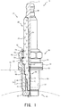
FIG. 1 is a one-side-sectional view of a spark plug according to a first embodiment of the present invention. -
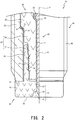
FIG. 2 is a partially enlarged one-side-sectional view of the spark plug. -
FIG. 3 is a one-side-sectional view of a spark plug according to a second embodiment. - Hereinafter, preferred embodiments of the present invention will be described with reference to the accompanying drawings without being limited thereto.
FIG. 1 is a one-side-sectional view of aspark plug 10 according to the first embodiment of the present invention, with an axial line O thereof as a boundary,FIG. 2 is a partially enlarged one-side-sectional view of thespark plug 10. InFIGS. 1 and2 , the lower side on the drawing sheet is referred to as a front side of thespark plug 10, and the upper side on the drawing sheet is referred to as a rear side of the spark plug 10 (the same applies toFIG. 3 ). InFIG. 2 , the rear side of thespark plug 10 in an axial line O direction is not shown. - As shown in
FIG. 1 , thespark plug 10 includes aninsulator 11, acenter electrode 50, and ametal shell 60. Theinsulator 11 is a member formed from alumina or the like which is excellent in mechanical property and insulation property at a high temperature. Theinsulator 11 includes afirst insulator 20 and asecond insulator 40. - In the
first insulator 20, atrunk portion 21, aprojection portion 22, a large-diameter portion 23, and a small-diameter portion 25 are connected in this order from the rear side to the front side along the axial line O, and a first throughhole 29, formed along the axial line O, penetrates through the center of thefirst insulator 20. Thetrunk portion 21 is located to the rear side of thefirst insulator 20. Thefirst insulator 20 has theprojection portion 22 projecting in a flange shape radially outward from a boundary between thetrunk portion 21 and the large-diameter portion 23. Theprojection portion 22 is formed around the entire circumference of the boundary between thetrunk portion 21 and the large-diameter portion 23. - The small-
diameter portion 25 provided to the front side of the large-diameter portion 23 includes a first small-diameter portion 26 and a second small-diameter portion 27. The second small-diameter portion 27 is disposed at the front side of the first small-diameter portion 26. An outer diameter of the first small-diameter portion 26 is larger than an outer diameter of the second small-diameter portion 27 and is smaller than an outer diameter of the large-diameter portion 23. Due to a difference between the outer diameter of the large-diameter portion 23 and the outer diameter of the first small-diameter portion 26, an engagement portion 24 (seeFIG. 2 ) facing toward the front side is formed on the outer circumference of the large-diameter portion 23. Theengagement portion 24 has a diameter that decreases toward the front side in the axial line O direction. An external thread portion 28 (seeFIG. 2 ) is formed on the outer circumference of the second small-diameter portion 27. - An inner diameter of the first through
hole 29 is made smaller by a step portion 30 (seeFIG. 2 ) formed in the large-diameter portion 23, and anaxial hole 31 is formed from the large-diameter portion 23 to the small-diameter portion 25. Thestep portion 30 and theaxial hole 31 are a part of the first throughhole 29. Thestep portion 30 has a diameter that decreases toward the front side in the axial line O direction. - The
second insulator 40 is a member that surrounds the periphery of the second small-diameter portion 27 of thefirst insulator 20. Thesecond insulator 40 includes acylindrical portion 41, and afront end portion 42 that is present at the front side with respect to the front end of themetal shell 60. An internal thread portion 43 (seeFIG. 2 ) is formed on the inner circumference of thecylindrical portion 41. Thefront end portion 42 is formed in a substantially disc shape. - As shown in
FIG. 2 , theinternal thread portion 43 is engaged with theexternal thread portion 28 formed on the outer circumference of the second small-diameter portion 27 of thefirst insulator 20, and thus directly joins thesecond insulator 40 to thefirst insulator 20. An outer diameter of thecylindrical portion 41 is substantially equal to the outer diameter of the first small-diameter portion 26 of thefirst insulator 20. A wall thickness of thecylindrical portion 41 in a radial direction is substantially equal to a difference between the outer diameter of the first small-diameter portion 26 and the outer diameter of the second small-diameter portion 27. A length of thecylindrical portion 41 in the axial line O direction is substantially equal to a length of the second small-diameter portion 27 in the axial line O direction. - In the
front end portion 42, a second throughhole 44 that penetrates the center along the axial line O is formed. In the second throughhole 44, ahole portion 45, anenlargement portion 46, and a diameter-enlargedportion 47 are connected to each other from the rear side to afront end 48 side. An inner diameter of thehole portion 45 is equal to an inner diameter of theaxial hole 31 formed in thefirst insulator 20. In a state where theinternal thread portion 43 is engaged with theexternal thread portion 28 so that thesecond insulator 40 is joined to thefirst insulator 20, thehole portion 45 becomes contiguous to theaxial hole 31. Theenlargement portion 46 is an annular portion that extends in an axial orthogonal direction perpendicular to the axial line O. The diameter-enlargedportion 47 is a portion that has an inner diameter larger than the inner diameter of thehole portion 45 and that is formed in a portion including thefront end 48 of theinsulator 11. - The portion including the
front end 48 of theinsulator 11 is a portion which is located at the front side in the axial line O direction of theinsulator 11 and in which thecenter electrode 50 is disposed. The diameter-enlargedportion 47 is formed so as to be connected to thefront end 48 of theinsulator 11. In the present embodiment, the diameter-enlargedportion 47 is formed on thesecond insulator 40 at which the front side of thecenter electrode 50 is disposed, and the inner diameter of the diameter-enlargedportion 47 gradually increases toward thefront end 48 side of thesecond insulator 40 up to thefront end 48. - The
center electrode 50 is a conductive member that includes anaxial portion 51 formed in a rod shape and anengagement portion 52 provided at the rear end of theaxial portion 51. Theengagement portion 52 is a portion that extends, as compared with theaxial portion 51, in the axial orthogonal direction orthogonal to the axial line O, and is engaged with thestep portion 30 of thefirst insulator 20. - In the
axial portion 51, a core material having a more excellent thermal conductivity than an electrode base material is embedded inside the electrode base material formed in a bottomed tubular shape. The core material is formed from copper or an alloy containing copper as a main component, and the electrode base material is formed from a nickel-based alloy, nickel, or the like. Theaxial portion 51 is disposed in theaxial hole 31 of thefirst insulator 20 and the second throughhole 44 of thesecond insulator 40. Theaxial portion 51 has a front end that is formed in a needle shape. The outer peripheral surface of theaxial portion 51 is spaced apart from the diameter-enlargedportion 47. In the present embodiment, thesecond insulator 40 surrounds the front end of theaxial portion 51 of thecenter electrode 50. In addition, the maximum outer diameter of a portion disposed in the diameter-enlargedportion 47, of theaxial portion 51, is smaller than the outer diameter of a portion disposed at the rear side with respect to the diameter-enlargedportion 47, of theaxial portion 51. - A description will be given returning to
FIG. 1 . Ametal terminal 56 is a rod-shaped member to which a high-voltage cable (not shown) is connected, and is formed from a metal material (e.g., low-carbon steel, etc.) having conductivity. The front side of themetal terminal 56 is disposed in the first throughhole 29 of thefirst insulator 20. A sealingmaterial 57 having conductivity is disposed between themetal terminal 56 and the engagement portion 52 (seeFIG. 2 ) of thecenter electrode 50. For the sealingmaterial 57, for example, a composition containing glass particles such as a B2O3-SiO2-based material and metal particles such as Cu or Fe is used. Via the sealingmaterial 57, thecenter electrode 50 and themetal terminal 56 are electrically connected to each other in the first throughhole 29. - The
metal shell 60 is a substantially cylindrical member that is fixed to aninternal combustion engine 76, and is formed from a metal material (e.g., low-carbon steel, stainless steel, etc.) having conductivity. In themetal shell 60, a crimpingportion 61, atool engagement portion 62, acurved portion 63, aseat portion 64, and atrunk portion 65 are connected in this order from the rear side to the front side along the axial line O. Athread portion 66 is formed on the outer peripheral surface of thetrunk portion 65. - The crimping
portion 61 and thecurved portion 63 are portions for crimping thefirst insulator 20. Thetool engagement portion 62 is a portion for engaging a tool such as wrench when thethread portion 66 is coupled with athread hole 77 of theinternal combustion engine 76. Theseat portion 64 is a portion that is located to the rear side of thetrunk portion 65 and that projects radially outward in an annular shape. Agasket 75 having an annular shape is disposed between theseat portion 64 and thetrunk portion 65. When themetal shell 60 is mounted to theinternal combustion engine 76, thegasket 75 seals a gap between thethread portion 66 and thethread hole 77. - As shown in
FIG. 2 , ashelf portion 67 that projects radially inward is provided on the inner circumference of thetrunk portion 65. Theshelf portion 67 has a diameter that decreases toward the front side in the axial line O direction. A packing 72 is disposed in theshelf portion 67. The packing 72 is an annular plate material formed from a metal material such as a mild metal plate. - A
front end 68 of the trunk portion 65 (the metal shell 60) is in contact with thefront end portion 42 of thesecond insulator 40. An outer diameter of thefront end portion 42 of thesecond insulator 40 is larger than the inner diameter (the inner diameter of the front end 68) of thetrunk portion 65 on afront end 68 side (the lower side ofFIG. 2 ) with respect to theshelf portion 67. Thecylindrical portion 41 of thesecond insulator 40 is present inside thetrunk portion 65 on the outer circumference of which thethread portion 66 is formed. - As shown in
FIG. 1 , a pair ofring members 73, andpowder 74, such as talc, that is interposed between the pair of thering members 73, are disposed between the inner circumference of thetool engagement portion 62 of themetal shell 60 and the outer circumference of thetrunk portion 21 of thefirst insulator 20. When the crimpingportion 61 of themetal shell 60 is deformed and is in close contact with thering member 73, theengagement portion 24 of thefirst insulator 20 is pressed toward theshelf portion 67 of themetal shell 60, via thering member 73, thepowder 74, and theprojection portion 22. Thus, themetal shell 60 is mounted to thefirst insulator 20 via the packing 72, thering member 73, and thepowder 74. The packing 72 airtightly closes a gap between theshelf portion 67 and theengagement portion 24. - The
spark plug 10 is manufactured by, for example, a method described below. First, theaxial portion 51 of thecenter electrode 50 is inserted into theaxial hole 31 of thefirst insulator 20, and theengagement portion 52 is caused to be engaged with thestep portion 30. Next, the first throughhole 29 is filled with a raw material powder of the sealingmaterial 57, themetal terminal 56 is pressed into the first throughhole 29 while being heated, and the raw material powder of the sealingmaterial 57 is compressed in an axial direction. The raw material powder is compressed and sintered, and electrical continuity between themetal terminal 56 and thecenter electrode 50 is ensured via the sealingmaterial 57. Then, while theaxial portion 51 of thecenter electrode 50 is inserted into the second throughhole 44 of thesecond insulator 40, theinternal thread portion 43 of thesecond insulator 40 is coupled with theexternal thread portion 28 of thefirst insulator 20, so that thesecond insulator 40 is joined to thefirst insulator 20. Lastly, themetal shell 60 is assembled to the outer circumferences of thefirst insulator 20 and thesecond insulator 40, so that thespark plug 10 is obtained. - In the
spark plug 10, when thethread portion 66 of themetal shell 60 is mounted into thethread hole 77 of the internal combustion engine 76 (seeFIG. 1 ), thefront end portion 42 of thesecond insulator 40 is exposed to a combustion chamber of theinternal combustion engine 76. When voltage is applied between themetal terminal 56 and themetal shell 60, gas partially undergoes dielectric breakdown in the vicinity of the front end of thecenter electrode 50, so that gaseous discharge (corona discharge) is formed. By the discharge, thespark plug 10 ionizes the gas (air-fuel mixture) to bring the gas into a plasma state, and generates flame kernel in the air-fuel mixture. - The
spark plug 10 has, in the portion including thefront end 48 of theinsulator 11, the diameter-enlargedportion 47 at which the diameter of the second throughhole 44 surrounding at least a part of thecenter electrode 50 is enlarged. Since the diameter-enlargedportion 47 is spaced apart from the outer peripheral surface of the center electrode 5, gaseous discharge occurs so as to expand in the radial direction in accordance with the shape of the diameter-enlargedportion 47. Thus, since discharge toward themetal shell 60 is difficult to occur, short circuit between thecenter electrode 50 and themetal shell 60 can hardly occur and gaseous discharge can easily occur. Therefore, the amount of plasma generated by thespark plug 10 can be ensured. - The second through
hole 44 has theenlargement portion 46 between thehole portion 45 and the diameter-enlargedportion 47. Since theenlargement portion 46 annularly extends in the axial orthogonal direction perpendicular to the axial line O, a spatial distance between the outer peripheral surface of thecenter electrode 50 and the diameter-enlargedportion 47 can be increased as compared with the case where theenlargement portion 46 is absent. As a result, the range of the diameter-enlargedportion 47 in which gaseous discharge is present can be extended in the radial direction, and thus ignitability can be improved. - Since the diameter-enlarged
portion 47 has an inner diameter that gradually increases toward thefront end 48 side of thesecond insulator 40 up to thefront end 48, gaseous discharge can be radially expanded to thefront end 48 side. Since the range in which gaseous discharge is present can be extended as compared with the case where the inner diameter of the diameter-enlargedportion 47 is the same in the axial line O direction, ignitability can be improved. - Since the diameter-enlarged
portion 47 is formed in the portion including thefront end 48 of the insulator 11 (in the present embodiment, a part of thefront end portion 42 of the second insulator 40), short circuit between thecenter electrode 50 and themetal shell 60 can be suppressed while heat dissipation performance of thecenter electrode 50 by theinsulator 11 is ensured. This is because in a case where the diameter-enlargedportion 47 is formed in theaxial hole 31 and thehole portion 45 from thestep portion 30 of theinsulator 11 to thefront end 48 side, a gap (diameter-enlarged portion 47) between thecenter electrode 50, and theaxial hole 31 and thehole portion 45 causes reduction in heat dissipation performance of thecenter electrode 50 by theinsulator 11. - Since the second insulator 40 (insulator 11) surrounds the outer circumference of the
center electrode 50 so as to reach at least the front end of thecenter electrode 50, short circuit between thecenter electrode 50 and themetal shell 60 is more difficult to occur as compared with the case where the front end of thecenter electrode 50 projects beyond thefront end 48 of thesecond insulator 40. Thus, gaseous discharge can more easily occur. - The maximum outer diameter of a part, of the
axial portion 51 of thecenter electrode 50, that is disposed in the diameter-enlargedportion 47 is smaller than the outer diameter of a part of theaxial portion 51 that is disposed at the rear side with respect to the diameter-enlargedportion 47. Therefore, a spatial distance between thecenter electrode 50 and the diameter-enlargedportion 47 can be increased. Thus, gaseous discharge in the diameter-enlargedportion 47 can easily occur. Thus, short circuit between thecenter electrode 50 and themetal shell 60 is more difficult to occur. Therefore, gaseous discharge can more easily occur. - Since the outer diameter of the
front end portion 42 of thesecond insulator 40 is larger than an inner diameter of thetrunk portion 65 at the front side (the lower side ofFIG. 2 ) with respect to theshelf portion 67, a creepage distance of thefront end portion 42 from the outer peripheral surface of thetrunk portion 65 to thecenter electrode 50 can be increased as compared with the case where the outer diameter of thefront end portion 42 is smaller than the inner diameter of thetrunk portion 65 at the front side with respect to theshelf portion 67. Thus, since surface discharge between thecenter electrode 50 and themetal shell 60 can hardly occur, gaseous discharge can easily occur. - The
insulator 11 includes: thefirst insulator 20 having theengagement portion 24 supported by theshelf portion 67; and thesecond insulator 40 having thefront end portion 42. In a case where theinsulator 11 is not divided into two members of thefirst insulator 20 and thesecond insulator 40, it is difficult to provide, at thefront end 68 of themetal shell 60, thefront end portion 42 having an outer diameter larger than a minimum inner diameter of theshelf portion 67. However, since thesecond insulator 40 is joined to thefirst insulator 20 at the front side with respect to theengagement portion 24, thefront end portion 42 having an outer diameter larger than an inner diameter of theshelf portion 67 can be easily provided without being restricted by the inner diameter of theshelf portion 67. - Since the
internal thread portion 43 of thesecond insulator 40 is coupled with theexternal thread portion 28 of thefirst insulator 20 so that thesecond insulator 40 is joined to thefirst insulator 20, joining reliability can be improved as compared with the case where thesecond insulator 40 is joined to thefirst insulator 20 by only an inorganic adhesive without using threads. - When the
internal thread portion 43 and theexternal thread portion 28 are provided, a creepage distance of each of the outer circumference of the second small-diameter portion 27 and the inner circumference of thecylindrical portion 41 can be increased as compared with the case where no thread is provided. Thus, short circuit, between themetal shell 60 and thecenter electrode 50, that has a path between the second small-diameter portion 27 and thecylindrical portion 41, can be suppressed. Since the area of contact between thefirst insulator 20 and thesecond insulator 40 can be increased by theinternal thread portion 43 and theexternal thread portion 28, heat transfer between thefirst insulator 20 and thesecond insulator 40 can be improved by theinternal thread portion 43 and theexternal thread portion 28. - Since the
internal thread portion 43 and theexternal thread portion 28 are formed radially inward of thethread portion 66 of themetal shell 60, heat transferred from thefirst insulator 20 to thesecond insulator 40 via theinternal thread portion 43 and theexternal thread portion 28 can be easily dissipated from thethread portion 66 of themetal shell 60 via thethread hole 77 to theinternal combustion engine 76. - The
front end 68 of the trunk portion 65 (the metal shell 60) is in contact with thefront end portion 42 of thesecond insulator 40. Therefore, in a state where theinternal thread portion 43 is coupled with theexternal thread portion 28, axial tension for tightening theexternal thread portion 28 and theinternal thread portion 43 can be ensured. Thus, since friction between a flank of theexternal thread portion 28 and a flank of theinternal thread portion 43 can be increased, theinternal thread portion 43 can be made difficult to loosen. - The
shelf portion 67 of themetal shell 60 projects, around the entire circumference of theshelf portion 67, inward in the axial orthogonal direction with respect to theengagement portion 24, and supports theengagement portion 24 of thefirst insulator 20 from the front side. Thus, when the large-diameter portion 23 provided to thefirst insulator 20 is supported by theshelf portion 67 of themetal shell 60, theinsulator 11 is held on the inner circumference of themetal shell 60. Since the large-diameter portion 23 is provided to thefirst insulator 20 that covers theaxial portion 51, a thickness of the large-diameter portion 23 in the axial orthogonal direction can be increased as compared to the case where the large-diameter portion 23 is provided to thesecond insulator 40 that covers the outer circumference of thefirst insulator 20. Thus, mechanical strength of the large-diameter portion 23 can be ensured. - In the
second insulator 40, thecylindrical portion 41 is present inside themetal shell 60. Therefore, thecylindrical portion 41 can be prevented from being exposed to combustion gas in a combustion chamber. Since overheating of thesecond insulator 40 can be suppressed as compared with the case where the entirety of thesecond insulator 40 is exposed to combustion gas, ignition of air-fuel mixture due to abnormal overheating of thesecond insulator 40 can be suppressed. - The
cylindrical portion 41 of thesecond insulator 40 is present inside thetrunk portion 65 on the outer circumference, of themetal shell 60, of which thethread portion 66 is formed. Thus, heat of thesecond insulator 40 can be transferred, via thecylindrical portion 41, thetrunk portion 65, and thethread portion 66, to theinternal combustion engine 76. Thus, since overheating of thesecond insulator 40 can be suppressed, ignition of air-fuel mixture due to abnormal overheating of thesecond insulator 40 can be further suppressed. - Of the
trunk portion 65, a portion on thefront end 68 side with respect to theshelf portion 67 has an equal inner diameter up to thefront end 68. Therefore, a wall thickness of thetrunk portion 65 on thefront end 68 side with respect to theshelf portion 67 can be ensured. Thus, heat capacity of thetrunk portion 65 that is present radially outward of thecylindrical portion 41 of thesecond insulator 40 can be ensured. Since the outer diameter of thecylindrical portion 41 is substantially equal to the outer diameter of the first small-diameter portion 26 of thefirst insulator 20, and the wall thickness of thecylindrical portion 41 in the radial direction is substantially equal to a difference between the outer diameter of the first small-diameter portion 26 and the outer diameter of the second small-diameter portion 27, a gap between thetrunk portion 65, and the first small-diameter portion 26 and thecylindrical portion 41 can be decreased. Thus, heat can be easily transferred from the first small-diameter portion 26 and thecylindrical portion 41 to thetrunk portion 65. Thus, since overheating of thesecond insulator 40 can be suppressed, ignition of air-fuel mixture due to abnormal overheating of thesecond insulator 40 can be further suppressed. - Since the
front end 68 of the trunk portion 65 (metal shell 60) is in contact with thefront end portion 42 of thesecond insulator 40, heat transfer from thefront end portion 42 to thetrunk portion 65 is not hampered. Thus, since overheating of thesecond insulator 40 can be suppressed, ignition of air-fuel mixture due to abnormal overheating of thesecond insulator 40 can be further suppressed. - With reference to
FIG. 3 , a second embodiment will be described. In the first embodiment, the case where thesecond insulator 40 is directly joined to thefirst insulator 20 has been described. On the other hand, in the second embodiment, the case where asecond insulator 81 is joined to thefirst insulator 20 via a filler 83 (another member) will be described. The same components as described in the first embodiment will be denoted by the same reference numerals, and the description thereof is not given.FIG. 3 is a one-side-sectional view of aspark plug 80 according to the second embodiment with an axial line O thereof as a boundary. InFIG. 3 , the rear side ofspark plug 80 is not shown. - As shown in
FIG. 3 , in thespark plug 80, thesecond insulator 81 is joined to thefirst insulator 20. In thesecond insulator 81, a plurality ofcorrugations 82 are formed on the outer peripheral surface of thefront end portion 42. In thespark plug 80, another member (filler 83) different from thefirst insulator 20 or thesecond insulator 81 is disposed at a gap between theinternal thread portion 43 of thesecond insulator 81 and theexternal thread portion 28 of thefirst insulator 20. Thefiller 83 has heat resistance and insulation property, and is in close contact with at least a part of theinternal thread portion 43 and theexternal thread portion 28. For thefiller 83, for example, the inorganic adhesive (that is, cement), a composition containing glass particles of a B2O3-SiO2-based material, or the like is used. Theinternal thread portion 43 and theexternal thread portion 28 are adhered to each other with thefiller 83. - Since the
filler 83 having insulation property is disposed at a gap between theinternal thread portion 43 and theexternal thread portion 28, and is in close contact with at least a part of theinternal thread portion 43 and theexternal thread portion 28, an effect of suppressing short circuit having a path between the second small-diameter portion 27 and thecylindrical portion 41 can be improved. Thefiller 83 is in close contact with theinternal thread portion 43 and theexternal thread portion 28, and therefore, depending on a coefficient of thermal conductivity of thefiller 83, thermal conductivity between theinternal thread portion 43 and theexternal thread portion 28 can be improved, and heat dissipation from thesecond insulator 40 to thefirst insulator 20 can be improved. - Since the
internal thread portion 43 and theexternal thread portion 28 are adhered to each other with thefiller 83, loosening of theinternal thread portion 43 with respect to theexternal thread portion 28 can be prevented. Thus, joining reliability of thesecond insulator 40 with respect to thefirst insulator 20 can be ensured. - Since the
second insulator 81 has the plurality ofcorrugations 82 on the outer peripheral surface of thefront end portion 42, the creepage distance of the outer peripheral surface of thefront end portion 42 can be increased as compared with the case where the corrugations are absent. Thus, since the surface discharge between thecenter electrode 50 and themetal shell 60 can hardly occur, gaseous discharge can more easily occur. - As described above, although the present invention has been described based on the embodiments, the present invention is not limited to the above embodiments at all. It can be easily understood that various modifications can be devised without departing from the gist of the present invention.
- In the above embodiments, the case where the
insulator 11 is divided into two members of thefirst insulator 20 and thesecond insulator 40, or thefirst insulator 20 and thesecond insulator 81, has been described. However, the present invention is not necessarily limited thereto. As a matter of course, theinsulator 11 in which thefirst insulator 20 and thesecond insulator 40, or thefirst insulator 20 and thesecond insulator 81 are integrated with each other can be used. In this case, members obtained by dividing themetal shell 60 into two parts are prepared, the members are mounted to the outer circumference of theinsulator 11 from both sides in the axial orthogonal direction of theinsulator 11, and then the members are welded to each other. Thus, themetal shell 60 can be mounted to the outer circumference of theinsulator 11. Also in a case where theinsulator 11 is formed from one member, the diameter-enlargedportion 47 is formed at a part where the center electrode 50 (specifically, the front end of the axial portion 51) is disposed in theinsulator 11, so as to be connected to thefront end 48 of theinsulator 11. - In the above embodiments, the case where the
second insulator first insulator 20 via theexternal thread portion 28 and theinternal thread portion 43 has been described. However, the present invention is not necessarily limited thereto. As a matter of course, thesecond insulator first insulator 20 using the inorganic adhesive without providing theexternal thread portion 28 and theinternal thread portion 43. - Although description is omitted in the above embodiments, the
external thread portion 28 and theinternal thread portion 43 are continuously provided or intermittently provided. Although description is omitted in the above embodiments, as a matter of course, thefiller 83 described in the second embodiment can be filled between theexternal thread portion 28 and theinternal thread portion 43 that have been described in the first embodiment. - In the above embodiments, the case where the
front end portion 42 of thesecond insulator front end 68 of themetal shell 60 has been described. However, the present invention is not necessarily limited thereto. In a case where thesecond insulator first insulator 20 using a thread, instead of themetal shell 60, thefront end portion 42 of thesecond insulator first insulator 20 in order to ensure tightening axial tension. In a case where theexternal thread portion 28 and theinternal thread portion 43 are omitted and thesecond insulator first insulator 20 using the inorganic adhesive, tightening axial tension is not required, so that thesecond insulator first insulator 20 or themetal shell 60. - Although, in the above embodiments, the
metal shell 60 is crimped into thefirst insulator 20 via thering member 73 and thepowder 74, the present invention is not necessarily limited thereto. As a matter of course, themetal shell 60 can be crimped without using thering member 73 and thepowder 74. -
- 10, 80: spark plug
- 11: insulator
- 20: first insulator
- 24: engagement portion
- 29: first through hole (through hole)
- 40, 81: second insulator
- 42: front end portion
- 44: second through hole (through hole)
- 47: diameter-enlarged portion
- 48: front end
- 50: center electrode
- 60: metal shell
- 66: thread portion
- 67: shelf portion
- 76: internal combustion engine
- 77: thread hole
- 83: filler (another member)
- O: axial line
Claims (5)
- A spark plug (10, 80) comprising:a center electrode (50) extending from a front side to a rear side along an axial line (0);an insulator (11) having a through hole (29, 44) that surrounds at least a part of the center electrode (50); anda metal shell (60) holding the insulator (11) from an outer peripheral side thereof and being substantially tubular,the metal shell (60) including a shelf portion (67) that projects radially inward,the insulator (11) including an engagement portion (24) that is engaged with the shelf portion (67) from the front side, and a front end portion (42) that is present at the front side with respect to a front end of the metal shell (60),at least a part of the front end portion (42) having an outer diameter larger than an inner diameter of the metal shell (60) at the front side with respect to the shelf portion (67), whereinthe insulator (11) has, in a portion including a front end of the insulator (11), a diameter-enlarged portion (47) at which a diameter of the through hole (44) increases and which is spaced apart from an outer peripheral surface of the center electrode (50).
- A spark plug (10, 80) according to claim 1, wherein the insulator (11) surrounds an outer circumference of the center electrode (50) so as to reach at least a front end of the center electrode (50).
- A spark plug (10, 80) according to claim 1 or 2, wherein the insulator (11) includes:a first insulator (20) having the engagement portion (24); anda second insulator (40, 81) having the front end portion (42), the second insulator (40, 81) being joined, directly or via another member (83), to the first insulator (20) at the front side with respect to the engagement portion (24).
- A spark plug (10, 80) according to claim 3, wherein a part of the second insulator (40, 81) is present inside the metal shell (60).
- A spark plug (10, 80) according to claim 3 or 4, wherein
the metal shell (60) has, on an outer peripheral surface thereof, a thread portion (66) screwed into a thread hole (77) of an internal combustion engine (76), and
at least a part of the second insulator (40, 81) is present inside a portion where the thread portion (66) is present, of the metal shell (60).
Applications Claiming Priority (1)
| Application Number | Priority Date | Filing Date | Title |
|---|---|---|---|
| JP2017069843A JP6524136B2 (en) | 2017-03-31 | 2017-03-31 | Spark plug |
Publications (1)
| Publication Number | Publication Date |
|---|---|
| EP3382830A1 true EP3382830A1 (en) | 2018-10-03 |
Family
ID=61731593
Family Applications (1)
| Application Number | Title | Priority Date | Filing Date |
|---|---|---|---|
| EP18162849.6A Withdrawn EP3382830A1 (en) | 2017-03-31 | 2018-03-20 | Spark plug |
Country Status (3)
| Country | Link |
|---|---|
| US (1) | US10581226B2 (en) |
| EP (1) | EP3382830A1 (en) |
| JP (1) | JP6524136B2 (en) |
Citations (7)
| Publication number | Priority date | Publication date | Assignee | Title |
|---|---|---|---|---|
| EP0622881A2 (en) * | 1993-04-26 | 1994-11-02 | Ngk Spark Plug Co., Ltd | A spark plug insulator a method of making the same |
| JP2009512172A (en) | 2005-10-18 | 2009-03-19 | ルノー・エス・アー・エス | Spark plug for automobile internal combustion engine |
| US20090189504A1 (en) * | 2005-04-08 | 2009-07-30 | Renault S.A.S. | Open-chamber multi-spark plug |
| WO2011128589A1 (en) * | 2010-04-16 | 2011-10-20 | Renault S.A.S. | Spark plug provided with a means for preventing short circuits |
| JP2013186999A (en) * | 2012-03-07 | 2013-09-19 | Ngk Spark Plug Co Ltd | Ignition system |
| EP2724430B1 (en) * | 2011-06-27 | 2015-03-18 | Federal-Mogul Ignition Company | Corona igniter assembly including corona enhancing insulator geometry |
| WO2016067209A1 (en) * | 2014-10-28 | 2016-05-06 | North-West University | Ignition plug |
Family Cites Families (2)
| Publication number | Priority date | Publication date | Assignee | Title |
|---|---|---|---|---|
| JP4966420B2 (en) * | 2010-03-09 | 2012-07-04 | 日本特殊陶業株式会社 | Plasma jet ignition plug and ignition system |
| DE102012108251B4 (en) * | 2011-10-21 | 2017-12-07 | Borgwarner Ludwigsburg Gmbh | Corona ignition device |
-
2017
- 2017-03-31 JP JP2017069843A patent/JP6524136B2/en not_active Expired - Fee Related
-
2018
- 2018-01-29 US US15/882,368 patent/US10581226B2/en not_active Expired - Fee Related
- 2018-03-20 EP EP18162849.6A patent/EP3382830A1/en not_active Withdrawn
Patent Citations (7)
| Publication number | Priority date | Publication date | Assignee | Title |
|---|---|---|---|---|
| EP0622881A2 (en) * | 1993-04-26 | 1994-11-02 | Ngk Spark Plug Co., Ltd | A spark plug insulator a method of making the same |
| US20090189504A1 (en) * | 2005-04-08 | 2009-07-30 | Renault S.A.S. | Open-chamber multi-spark plug |
| JP2009512172A (en) | 2005-10-18 | 2009-03-19 | ルノー・エス・アー・エス | Spark plug for automobile internal combustion engine |
| WO2011128589A1 (en) * | 2010-04-16 | 2011-10-20 | Renault S.A.S. | Spark plug provided with a means for preventing short circuits |
| EP2724430B1 (en) * | 2011-06-27 | 2015-03-18 | Federal-Mogul Ignition Company | Corona igniter assembly including corona enhancing insulator geometry |
| JP2013186999A (en) * | 2012-03-07 | 2013-09-19 | Ngk Spark Plug Co Ltd | Ignition system |
| WO2016067209A1 (en) * | 2014-10-28 | 2016-05-06 | North-West University | Ignition plug |
Also Published As
| Publication number | Publication date |
|---|---|
| JP6524136B2 (en) | 2019-06-05 |
| JP2018174036A (en) | 2018-11-08 |
| US20180287349A1 (en) | 2018-10-04 |
| US10581226B2 (en) | 2020-03-03 |
Similar Documents
| Publication | Publication Date | Title |
|---|---|---|
| JP6238895B2 (en) | Corona igniter with temperature control function | |
| US10153618B2 (en) | Spark plug | |
| EP2916403B1 (en) | Ignition plug | |
| CN107689555B (en) | Spark plug and ignition device | |
| US11025037B2 (en) | Arrester for protection against overvoltages | |
| US8294344B2 (en) | Spark plug and weld metal zone | |
| US7768183B2 (en) | Extension spark plug | |
| JP4425741B2 (en) | Spark plug and internal combustion engine equipped with the same | |
| US10581226B2 (en) | Spark plug | |
| JP7063125B2 (en) | Spark plugs for internal combustion engines and ignition devices for internal combustion engines | |
| JP6775460B2 (en) | Spark plug | |
| US20200412104A1 (en) | Spark plug | |
| US10178751B2 (en) | Ignition plug | |
| EP3382829B1 (en) | Spark plug | |
| US9059572B2 (en) | Spark plug with center electrode for internal combustion engine | |
| JP5875895B2 (en) | Connector for connecting spark plug and coaxial structure, and spark plug to which connector is attached | |
| JP6207573B2 (en) | Insulator inspection method for spark plug | |
| JP6767936B2 (en) | Spark plug and ignition device | |
| JP2013186999A (en) | Ignition system | |
| JPWO2019069640A1 (en) | Spark plug | |
| JP2021009821A (en) | Spark plug |
Legal Events
| Date | Code | Title | Description |
|---|---|---|---|
| PUAI | Public reference made under article 153(3) epc to a published international application that has entered the european phase |
Free format text: ORIGINAL CODE: 0009012 |
|
| STAA | Information on the status of an ep patent application or granted ep patent |
Free format text: STATUS: THE APPLICATION HAS BEEN PUBLISHED |
|
| AK | Designated contracting states |
Kind code of ref document: A1 Designated state(s): AL AT BE BG CH CY CZ DE DK EE ES FI FR GB GR HR HU IE IS IT LI LT LU LV MC MK MT NL NO PL PT RO RS SE SI SK SM TR |
|
| AX | Request for extension of the european patent |
Extension state: BA ME |
|
| STAA | Information on the status of an ep patent application or granted ep patent |
Free format text: STATUS: REQUEST FOR EXAMINATION WAS MADE |
|
| 17P | Request for examination filed |
Effective date: 20190122 |
|
| RBV | Designated contracting states (corrected) |
Designated state(s): AL AT BE BG CH CY CZ DE DK EE ES FI FR GB GR HR HU IE IS IT LI LT LU LV MC MK MT NL NO PL PT RO RS SE SI SK SM TR |
|
| STAA | Information on the status of an ep patent application or granted ep patent |
Free format text: STATUS: EXAMINATION IS IN PROGRESS |
|
| 17Q | First examination report despatched |
Effective date: 20200408 |
|
| STAA | Information on the status of an ep patent application or granted ep patent |
Free format text: STATUS: THE APPLICATION IS DEEMED TO BE WITHDRAWN |
|
| 18D | Application deemed to be withdrawn |
Effective date: 20220203 |