EP3382648A1 - Three-dimensional model generating system, three-dimensional model generating method, and program - Google Patents
Three-dimensional model generating system, three-dimensional model generating method, and program Download PDFInfo
- Publication number
- EP3382648A1 EP3382648A1 EP16890486.0A EP16890486A EP3382648A1 EP 3382648 A1 EP3382648 A1 EP 3382648A1 EP 16890486 A EP16890486 A EP 16890486A EP 3382648 A1 EP3382648 A1 EP 3382648A1
- Authority
- EP
- European Patent Office
- Prior art keywords
- body shape
- dimensional model
- parameter
- skeleton
- model
- Prior art date
- Legal status (The legal status is an assumption and is not a legal conclusion. Google has not performed a legal analysis and makes no representation as to the accuracy of the status listed.)
- Pending
Links
Images


Classifications
-
- G—PHYSICS
- G06—COMPUTING; CALCULATING OR COUNTING
- G06T—IMAGE DATA PROCESSING OR GENERATION, IN GENERAL
- G06T17/00—Three dimensional [3D] modelling, e.g. data description of 3D objects
-
- G—PHYSICS
- G06—COMPUTING; CALCULATING OR COUNTING
- G06T—IMAGE DATA PROCESSING OR GENERATION, IN GENERAL
- G06T13/00—Animation
- G06T13/20—3D [Three Dimensional] animation
- G06T13/40—3D [Three Dimensional] animation of characters, e.g. humans, animals or virtual beings
-
- G—PHYSICS
- G06—COMPUTING; CALCULATING OR COUNTING
- G06T—IMAGE DATA PROCESSING OR GENERATION, IN GENERAL
- G06T7/00—Image analysis
-
- G—PHYSICS
- G06—COMPUTING; CALCULATING OR COUNTING
- G06T—IMAGE DATA PROCESSING OR GENERATION, IN GENERAL
- G06T7/00—Image analysis
- G06T7/50—Depth or shape recovery
-
- G—PHYSICS
- G06—COMPUTING; CALCULATING OR COUNTING
- G06T—IMAGE DATA PROCESSING OR GENERATION, IN GENERAL
- G06T2207/00—Indexing scheme for image analysis or image enhancement
- G06T2207/20—Special algorithmic details
- G06T2207/20036—Morphological image processing
- G06T2207/20044—Skeletonization; Medial axis transform
Landscapes
- Engineering & Computer Science (AREA)
- Physics & Mathematics (AREA)
- General Physics & Mathematics (AREA)
- Theoretical Computer Science (AREA)
- Computer Vision & Pattern Recognition (AREA)
- Computer Graphics (AREA)
- Geometry (AREA)
- Software Systems (AREA)
- Image Analysis (AREA)
- Processing Or Creating Images (AREA)
- Image Processing (AREA)
Abstract
Description
- The present invention relates to a three-dimensional model generating system, a three-dimensional model generating method, and a program.
- A technique for measuring an image capturing object, such as people or animals, with a depth detecting device to generate a three-dimensional (3D) model is conventionally known. For example, Non-Patent
Literature 1 describes a technique for generating a 3D model by photographing an image capturing object from different directions with a plurality of RGBD cameras and inferring the body line of the image capturing object on the basis of the contour information and depth information of the image capturing object obtained with these RGBD cameras. For example, Non-PatentLiterature 2 describes a technique for deforming a 3D model so as to match with the arms and legs having the lengths indicated by the depth information obtained by a single RGBD camera. -
- Non-Patent Literature 1: A. Weiss, D. Hirshberg, and M. J.B lack. Home 3d body scans from noisy image and range data. ICCV, 2011.
- Non-Patent Literature 2: Q. Wang, V. Jagadeesh, B. Ressler, and R. Piramuthu. Im2fit: Fast 3d model fitting and anthropometrics using single consumer depth camera and synthetic data. arXiv, 2014.
- However, the technique described in
Non-Patent Literature 1 requires many RGBD cameras and thus a dedicated photo studio or other facilities. Further, need of analysis of the RGBD images obtained by photographing an image capturing object from different directions may complicate the processing, taking time to generate a 3D model. Furthermore, according the technique disclosed in Non-PatentLiterature 2, as a 3D model is deformed simply based on the lengths of arms and legs, the dimension of the image capturing object cannot be precisely estimated, which generates, for example, a larger 3D model than the real image capturing object. That is, a highly precise 3D model cannot be generated. - The present invention has been conceived in view of the above, and it is an object of the present invention to quickly generate a highly precise 3D model.
- In order to achieve the above objects, a three-dimensional model generating system according to the present invention includes skeleton obtaining means for obtaining a skeleton parameter, based on depth information of an object, wherein the depth information is detected by a depth detecting device; posture changing means for changing a posture of a three-dimensional model that is able to be deformed based on a body shape parameter, based on the skeleton parameter; surface shape obtaining means for obtaining a surface shape of the object, based on the depth information; body shape determining means for determining the body shape parameter, based on a difference between a surface shape of the three-dimensional model having the posture changed by the posture changing means and the surface shape of the object; and body shape deforming means for deforming the three-dimensional model, based on the body shape parameter determined by the body shape parameter determining means.
- A three-dimensional model generating method according to the present invention includes a skeleton obtaining step of obtaining a skeleton parameter, based on depth information of an object detected by a depth detecting device; a posture changing step of changing a posture of a three-dimensional model that is able to be deformed based on a body shape parameter, based on the skeleton parameter; a surface shape obtaining step of obtaining a surface shape of the object, based on the depth information; a body shape determining step of determining the body shape parameter, based on a difference between a surface shape of the three-dimensional model having the posture changed at the posture changing step and the surface shape of the object; and a body shape deforming step of deforming the three-dimensional model, based on the body shape parameter determined at the body shape parameter determining step.
- A program according to the present invention causes a computer to function as: skeleton obtaining means for obtaining a skeleton parameter, based on depth information of an object detected by a depth detecting device; posture changing means for changing a posture of a three-dimensional model that is able to be deformed based on a body shape parameter, based on the skeleton parameter; surface shape obtaining means for obtaining a surface shape of the object, based on the depth information; body shape determining means for determining the body shape parameter, based on a difference between a surface shape of the three-dimensional model having the posture changed by the posture changing means and the surface shape of the object; and body shape deforming means for deforming the three-dimensional model, based on the body shape parameter determined by the body shape parameter determining means.
- A computer readable information storage medium according to the present invention stores the above-described program.
- According to one aspect of the present invention, the three-dimensional model generating system may further include skeleton determining means for determining the skeleton parameter, based on a difference between the surface shape of the three-dimensional model and the surface shape of the object, wherein the posture changing means updates the posture of the three-dimensional model, based on the skeleton parameter determined by the skeleton determining means.
- According to one aspect of the present invention, the three-dimensional model generating system may further include partial deforming means for deforming a part of the surface shape of the three-dimensional model deformed by the body shape deforming means, based on a difference in surface shape between the part and a corresponding part of the object.
- According to one aspect of the present invention, the three-dimensional model generating system may further include detection range specifying means for specifying a part corresponding to a detection range of the depth detecting device from among the three-dimension model, based on the depth information, wherein the partial deforming means deforms the part specified by the detection range specifying means at the three-dimension model.
- According to one aspect of the present invention, the partial deforming means deforms each part of the three-dimensional model, based on a deforming extent of an environment of the part.
- According to one aspect of the present invention, the partial deforming means deforms each part of the three-dimensional model, based on a previous shape of the part.
- According to one aspect of the present invention, the three-dimensional model generating system may further include body portion identifying means for identifying a body portion corresponding to a body of the object from among the three-dimensional model, based on the surface shape of the three-dimensional model or the object, wherein the body shape determining means makes larger a weight for a difference relevant to the body portion than a weight for a difference relevant to other portions when determining the body shape parameter.
- According to one aspect of the present invention, the three-dimensional model generating system may further include detection range specifying means for specifying a vertex corresponding to a detection range of the depth detecting device from among the three-dimensional model, based on the depth information, wherein the body shape determining means determines the body shape parameter, based on a difference between the surface shape of the three-dimensional model in the detection range and the surface shape of the object in the detection range.
- According to one aspect of the present invention, the three-dimensional model generating system may further include history recording means for recording a history of the body shape parameter in storage means, wherein the body shape determining means determines the body shape parameter, based on the history recorded by the history recording means.
- According to the present invention, it is possible to quickly generate a highly precise 3D model.
-
-
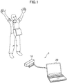
FIG. 1 illustrates a situation in which an object is photographed in a 3D model generating system; -
FIG. 2 illustrates the hardware structure of a 3D model generating system; -
FIG. 3 illustrates one example of depth information; -
FIG. 4 illustrates one example of detected posture information; -
FIG. 5 outlines the processing executed in a 3D model generating system; -
FIG. 6 is a functional block diagram of one example of the functions implemented in a 3D model generating system; -
FIG. 7 illustrates a skeleton parameter; -
FIG. 8 illustrates a 3D model being deformed based on a skeleton parameter; -
FIG. 9 illustrates a 3D model whose posture is being changed based on a skeleton parameter; -
FIG. 10 illustrates a 3D model whose posture is being changed based on a skeleton parameter; -
FIG. 11 is a diagram to explain the processing by a detection range specifying unit; -
FIG. 12 is a diagram to explain the processing by a body shape determining unit; -
FIG. 13 indicates a 3D model being changed through optimization; -
FIG. 14 is a diagram to explain a vertex movement amount; -
FIG. 15 illustrates a 3D model; -
FIG. 16 is a flowchart of one example of the processing executed in a 3D model generating system; -
FIG. 17 illustrates details of shape inferring processing; and -
FIG. 18 illustrates details of geometric restructuring processing. - The following describes an example of an embodiment of a 3D model generating system according to the present invention.
FIG. 1 illustrates a situation in which an image capturing object (or an object) is photographed in a 3D model generating system.FIG. 2 illustrates the hardware structure of the 3D model generating system. As illustrated inFIGs. 1 and2 , the 3Dmodel generating system 1 includes adepth detecting device 10 and a 3Dmodel generating device 20. Thedepth detecting device 10 and the 3Dmodel generating device 20 are connected to each other so as to exchange data through wired or radio communication. - The
depth detecting device 10 is a measuring device that detects the depth of an object. For example, thedepth detecting device 10 may be a Kinect (registered trademark) sensor. A depth refers to the distance between thedepth detecting device 10 and the object. The object is a moving object to be detected and may be, for example, a person, an animal, or clothes he/she/it wears. - The
depth detecting device 10 includes acontrol unit 11, astorage unit 12, acommunication unit 13, and adepth detecting unit 14. Thecontrol unit 11 includes, for example, one or more microprocessors. Thecontrol unit 11 executes processing according to a program and data stored in thestorage unit 12. Thestorage unit 12 includes a main storage unit and an auxiliary storage unit. For example, the main storage unit is a volatile memory, such as a RAM, while the auxiliary storage unit is a non-volatile memory, such as a hard disk or a flash memory. Thecommunication unit 13 includes a network card for wired or radio communication. Thecommunication unit 13 executes data communication via a network. - The
depth detecting unit 14 is a depth sensor (a distance camera) that detects a depth, using electromagnetic waves, sound waves, or the like. Thedepth detecting unit 14 may be, for example, an RGBD camera or a supersonic sensor. Although the following describes a case in which thedepth detecting unit 14 includes an RGBD camera and detects the depth of an object, using infrared radiation, thedepth detecting unit 14 can be implemented using publicly known various types of depth sensors. - For example, the RGBD camera of the
depth detecting unit 14 includes either a CMOS image sensor or a CCD image sensor and an infrared sensor. Thedepth detecting unit 14 generates an RGB image of an object, based on a detection signal from the CMOS image sensor or the CCD image sensor. An RGB image is two-dimensional (2D) information of an object and does not include depth information. Specifically, thedepth detecting unit 14 emits infrared light from a light emitting element of an infrared sensor and detects infrared light reflected by an object with a light receiving element. Thedepth detecting unit 14 then estimates the distance to the object, based on the traveling time of the infrared light, or a period of time since emission of the infrared light until receipt of the returned infrared light, to generate depth information. As a method for generating depth information, any of various known methods can be employed, and a light coding method can be used besides the above-mentioned method that detects a traveling time. -
FIG. 3 illustrates one example of the depth information. As illustrated inFIG. 3 , the depth information I here is expressed as a depth image. Thus, each of the pixels in the depth information I is associated with a pixel value indicating a depth. The depth information I may be an image different from an RGB image or may be an RGBD image, or an integrated image of the depth information I and an RGB image. In the case of an RGBD image used as the depth information I, the pixel value of each pixel includes the value of a depth channel in addition to the value of each color channel. In this embodiment, a case in which the depth information I is an image different from an RGB image will be described. - The
depth detecting device 10 estimates the position of each of the joints of the object, based on the depth information I detected by thedepth detecting unit 14, to obtain a skeleton. Although a skeleton can be obtained using various known extraction methods, a method utilizing template matching is described here as an example. For example, thedepth detecting device 10 executes template matching between the depth information I detected by thedepth detecting unit 14 and a template image showing the basic shape of the contour of the object to thereby estimate the position (a pixel) of each of the joints of the object, the joints included in the depth information I. Then, thedepth detecting device 10 applies predetermined matrix conversion to the depth of each of the joints to thereby estimate the 3D position of the joint. The estimated positions of the respective joints determine the posture of the skeleton and will be hereinafter referred to as detected posture information. -
FIG. 4 illustrates one example of the detected posture information. As illustrated inFIG. 4 , the detected posture information J includes the 3D coordinate of the respective joints of the object. A case in which the detected posture information J contains the 3D coordinates of a head J1, a point between shoulders J2, a right shoulder J3, a right elbow J4, a right hand J5, a left shoulder J6, a left elbow J7, a left hand J8, a spine J9, a center hip J10, a right hip J11, a right knee J12, a right foot J13, a left hip J14, a left knee J15, and a left foot J16 will be described here. InFIG. 4 , which illustrates the object viewed from thedepth detecting device 10, the left and right positional relationship appears opposite from the actual one. The number of joints included in the detected posture information J can be fewer or greater than the above-mentioned number, namely, sixteen. The detected posture information J indicates the position of a joint that can be determined based on the depth information I, and may include, for example, the position of a wrist or an ankle in addition to the positions mentioned above. - In this embodiment, the
depth detecting device 10 generates the depth information I and the detected posture information J at a predetermined frame rate. In other words, thedepth detecting device 10 regularly generates the depth information I and the detected posture information J. For example, assuming that the frame rate is at 30 fps, thedepth detecting device 10 generates the depth information I and the detected posture information J for every 1/30th of a second. In the case where the depth information I and the detected posture information J at a certain time t are referred to, characters It and Jt will be hereinafter used as the respective reference characters. - The 3D
model generating device 20 is a computer that generates a 3D model, including, for example, a personal computer, a personal digital assistant (including a tablet computer), or a portable phone (including a smart phone). The 3Dmodel generating device 20 includes acontrol unit 21, astorage unit 22, acommunication unit 23, anoperation unit 24, and adisplay unit 25. The hardware structures of thecontrol unit 21, thestorage unit 22, and thecommunication unit 23 are similar to those of thecontrol unit 11, thestorage unit 12, and thecommunication unit 13, respectively, and will not be described here. - The
operation unit 24 is an input device for a player to use to operate, including, for example, a pointing device, such as a touch panel or a mouse, or a keyboard. Theoperation unit 24 transmits the content of an operation by a player to thecontrol unit 21. Thedisplay unit 25 is, for example, a liquid crystal display unit or an organic EL display. Thedisplay unit 25 displays a screen image in response to an instruction from thecontrol unit 21. - A program and data, described here as being stored in the
storage units storage units depth detecting device 10 and the 3Dmodel generating device 20 can be any structures not limited to those mentioned above, and various pieces of computer hardware are applicable. For example, each of thedepth detecting device 10 and the 3Dmodel generating device 20 may include a reading unit (for example, an optical disk drive or a memory card slot) that reads a computer readable information storage medium. In this case, a program and data stored in an information storage medium can be supplied to thedepth detecting device 10 and the 3Dmodel generating device 20 via the reading unit. -
FIG. 5 outlines the processing executed by the 3Dmodel generating system 1, in which t indicates a time axis. As illustrated inFIG. 5 , thedepth detecting device 10 regularly sends the depth information I and the detected posture information J to the 3Dmodel generating device 20. The 3Dmodel generating device 20 receives the depth information I and the detected posture information J at the beginning of each frame and then executes shape inferring processing for inferring the shape of the body (a body line) of an object and geometric restructuring processing for restructuring partial detailed shape (for example, clothes wrinkle), based on the inferred body line. The shape inferring processing and the geometric restructuring processing are executed for every frame. - In the shape inferring processing, a template showing the basic shape of a body is deformed so as to have a posture and a body shape similar to those of the object. The template is a 3D model that represents a body itself and may be, for example, a naked 3D model. The template is composed of a plurality of parts each representing a portion of the body. The template may be prepared in advance using photographed data of the object or 3D CAD. When a template is referred to, the reference character "MT" will be hereinafter added to a 3D model. When a 3D model deformed in the shape inferring processing is referred to, the reference character "MS" will be hereinafter added to a 3D model. A 3D model MS can be rephrased as a naked 3D model reproducing the posture and body shape of an object.
- In the geometric restructuring processing, the 3D model MS is partially restructured, using the depth information I, such that the detailed shapes, such as clothes wrinkle (the shape of a portion other than the body) are reproduced. When a 3D model in this condition is referred to, the reference character "MD" will be hereinafter used. That is, a 3D model MD is a 3D model reproducing not only the body line of an object but also what the object wears. With the 3D model MD, the body of the object and the other portions are distinguishable from each other, as to be described later in detail. Supply of the result of geometric restructuring processing to the shape inferring processing can enhance the precision of the 3D model MS.
- In this embodiment, the precision of the 3D models MS, MD is evaluated, using the Bayesian Inference Theory, to improve the precision. The Bayesian Inference Theory is a method for inferring, in a probability point of view, an item to be inferred (or an inference target), based on the result of detection in the real world. The higher the probability according to the Bayesian Inference Theory is, the more likely the inference target actually comes true. In other words, the higher the probability according to the Bayesian Inference Theory is, the more similar to the real object the inferred 3D models MS, MD are.
- The 3D
model generating system 1 determines how much to deform the 3D model MT as a whole and how much to partially restructure the 3D model MT in order to enhance the probability according to the Bayesian Inference Theory. In this embodiment, three evaluation values, namely, evaluation values ES, ED, and E0, are used to enhance the probability to quickly generate a highly precious 3D model. Specifically, the evaluation value ES is used to evaluate the extent of an overall deviation between the 3D model MS and the object; the evaluation value ED is used to evaluate a partial deviation between the 3D model MD and the object; the evaluation value E0 is used to prevent such a sharp change that cannot be true. The details of this technique will be described below. -
FIG. 6 is a functional block diagram of one example of the functions implemented in the 3Dmodel generating system 1. As illustrated inFIG. 6 , a case in which adata storage unit 30, adepth obtaining unit 31, askeleton obtaining unit 32, a bodyshape obtaining unit 33, aposture changing unit 34, a detectionrange specifying unit 35, a surfaceshape obtaining unit 36, a bodyshape determining unit 37, ahistory recording unit 38, a bodyshape deforming unit 39, askeleton determining unit 40, apartial deforming unit 41, and a bodyportion identifying unit 42 are implemented in the 3Dmodel generating device 20 will be described in this embodiment. The bodyshape determining unit 37 and theskeleton determining unit 40 execute the main processing of the shape inferring processing, while thepartial deforming unit 41 executes the main processing of the geometric restructuring processing. - The
data storage unit 30 is implemented using mainly thestorage unit 22. Thedata storage unit 30 stores data for generating 3D models MS, MD. As examples of data stored in thedata storage unit 30, the following will be described: - (1) depth history data including the history of the depth information I;
- (2) skeleton history data including the history of the skeleton parameter (to be described later in detail);
- (3) body shape history data including the history of the body shape parameter (to be described later in detail)
- (4) movement amount history data including the history of the vertex movement amount (to be described later in detail);
- (5) template data defining a 3D model MT;
- (6) body history data including the history of the 3D model MS; and
- (7) restructuring history data including the history of the 3D model MD.
- The data stored in the
data storage unit 30 is not limited to the above-mentioned examples. For example, thedata storage unit 30 may store data including the history of the detected posture information J or data indicating the basic posture of the skeleton JT. - The
depth obtaining unit 31 is implemented using mainly thecontrol unit 21. Thedepth obtaining unit 31 obtains the depth information I of the object, the depth information I being detected by the depth detecting device 10 (FIG. 3 ). In this embodiment, as the 3Dmodel generating device 20 is directly connected to thedepth detecting device 10, thedepth obtaining unit 31 receives the depth information I directly from thedepth detecting device 10. Alternatively, thedepth obtaining unit 31 may indirectly receive the depth information I via other devices. Thedepth obtaining unit 31 includes the received depth information in the depth history data. - The
skeleton obtaining unit 32 is implemented using mainly thecontrol unit 21. Theskeleton obtaining unit 32 obtains the skeleton parameter of the object, based on the depth information I obtained by thedepth detecting device 10. The skeleton parameter is information on the skeleton of the object and indicates the positional relationship of each joint. Although the detected posture information J illustrated inFIG. 4 can be used intact as a skeleton parameter, a case in which theskeleton obtaining unit 32 uses the angle of each of the joints indicated by the detected posture information J as a skeleton parameter will be described here. Theskeleton obtaining unit 32 includes the obtained skeleton parameter in the skeleton history data. -
FIG. 7 illustrates a skeleton parameter. As illustrated inFIG. 7 , theskeleton obtaining unit 32 calculates the angle {θj} of each of the joints indicated by the detected posture information J, based on the 3D coordinates of the joint, as a skeleton parameter. Of the joints indicated by the detected posture information J, the joints other than the end joints each have an angle. In the example inFIG. 7 , the skeleton parameter {θj} is composed of twelve angles. A skeleton parameter {θj} at a certain time t will be hereinafter denoted as {θtj}. - The body shape parameter obtaining unit is implemented using mainly the
control unit 21. The body shape parameter obtaining unit obtains a body shape parameter. In this embodiment, a 3D model MT that has been deformed based on the body shape parameter makes a 3D model MS. "To morph" here means to change the position and/or the shape of a surface, including, for example, change in the entire dimension or change in a partial shape. The bodyshape obtaining unit 33 includes the obtained body shape parameter in the body shape history data. - The body shape parameter indicates the characteristics of the body shape of an object, specifically, the dimension of the full body or each portion. For example, the body shape parameter includes the values of a height, a chest, a waist, a width, an inseam, arm lengths, or foot sizes. In this embodiment, the body shape parameter is a combination of a plurality of values and denoted as {βk}, wherein k is a number that identifies an item included in the body shape parameter, for example, β1 for a height, β2 for a chest, β3 for a waist, and the like. Alternatively, the body shape parameter may be a single value rather than a combination of values.
-
FIG. 8 illustrates the 3D model MT being deformed based on the body shape parameters {βk}. As illustrated inFIG. 8 , the 3D model MT is deformed so as to have the body shape indicated by the body shape parameters {βk}. For example, the 3D model MT is deformed so as to be shorter in response to a smaller β1 and taller in response to a larger β1. For example, the 3D model MT is deformed so as to have a smaller chest in response to a smaller β2 and a larger chest in response to a larger β2. For example, a 3D model MT is deformed so as to have a thinner waist in response to a smaller β3 and a thicker waist in response to a larger β3. - The relationship between the body shape parameter {βk} and the shape of each part of the 3D model MT (that is, the position of a vertex) is assumed to be stored in advance in the
data storage unit 30. This relationship may be expressed in the form of an expression, a table, or a program code. This relationship is defined such that the 3D model MT is deformed so as to have the body shape indicated by the body shape parameter {βk}. The bodyshape deforming unit 39 to be described later deforms the respective parts of the 3D model MT so as to have the respective shapes associated with the respective body shape parameters {βk}, whereby the 3D model MT is deformed so as to have a body shape in accordance with the body shape parameters {βk}. - A body shape parameter {βk} at a certain time t will be hereinafter denoted as {βt k}. Assuming that the time when the depth information I is initially obtained (that is, the start of the processing according to the present invention) is defined as t=0, the body shape parameter {β0 k} at that time has the initial value, which is a value indicating the body shape of the
template 3D model MT. The body shape parameter {β0 k} may be stored in advance in thedata storage unit 30. At t=0, the bodyshape obtaining unit 33 obtains the body shape parameter {β0 k} at the initial value stored in thedata storage unit 30. - The
posture changing unit 34 is implemented using mainly thecontrol unit 21. Theposture changing unit 34 changes the posture of the 3D model MT, based on the skeleton parameter {θj}, wherein the 3D model MT can be deformed based on the body shape parameters {βk}. Specifically, theposture changing unit 34 changes the positional relationship between the respective parts of the 3D model MT such that the 3D model MT has a posture indicated by the skeleton parameter {θj}. The posture corresponds to the positional relationship between the portions of the body, that is, the positional relationship of each joint here. -
FIGs. 9 and10 illustrate the 3D model MT whose posture is being changed based on the skeleton parameter {θj}. As illustrated inFIG. 9 , initially, theposture changing unit 34 sets a skeleton JT in the basic posture (for example, standing upright) inside the 3D model MT. The positional relationship of each of the joints constituting the skeleton JT is defined in advance so as to define the posture of thetemplate 3D model MT. With the skeleton JT set inside the 3D model MT, each of the vertexes of the 3D model MT is made associated with any of the joints of the skeleton JT. When the skeleton JT is deformed and each of the joints accordingly moves, a vertex associated with a joint moves so as to maintain a predetermined positional relationship with the joint. That is, a vertex associated with a joint interlinks with the joint. - The
posture changing unit 34 deforms the skeleton JT such that the positional relationship of each of the joints indicated by the skeleton parameter {θj} matches with the positional relationship of the corresponding joint of the skeleton JT. That positional relationships match with each other means that the positions of the two relevant joints coincide with each other or deviate from each other by an amount less than a predetermined amount. Some positional deviation is tolerated because the distance between the real joints of the object does not always coincide with the distance between the corresponding joints of the skeleton JT, and complete matching of such 3D coordinates is difficult to achieve. - In this embodiment, for overall resemblance in posture, the
posture changing unit 34 deforms the skeleton JT such that the angles of the respective joints of the skeleton JT match with, or deviate from by an amount less than a reference value, the skeleton parameter {θj}. As described above, the respective vertexes of the 3D model MT interlink with the respective associated joints. Thus, as illustrated inFIG. 10 , deforming the skeleton JT by theposture changing unit 34 can produce a 3D model MS in a posture similar to the posture of the object. - The detection
range specifying unit 35 is implemented using mainly thecontrol unit 21. The detectionrange specifying unit 35 specifies a part of the 3D model MS, based on the depth information I, the part corresponding to the range (or a detection range) detected by thedepth detecting device 10. In other words, the detection range is a detectable area on the surface of the object, that is, an area where infrared light from thedepth detecting device 10 reflects. For example, the detectionrange specifying unit 35 determines the orientation of thedepth detecting device 10 in a 3D space, based on the depth information I, and specifies a detection range, based on the relationship between the determined orientation and the orientation of the surface of the 3D model MS. -
FIG. 11 is a diagram to explain the processing by the detectionrange specifying unit 35. As illustrated inFIG. 11 , the direction V of the line of sight (or the sight line direction V) (that is, the direction of emission of the infrared light) of thedepth detecting device 10 is used as the orientation of thedepth detecting device 10. The detectionrange specifying unit 35 obtains a view point OV and the sight line direction V in the 3D space, based on the depth information I. The view point OV is the origin of the viewpoint coordinate system, and the sight line direction V is the Z axis of the viewpoint coordinate system (the coordinate axes inFIG. 11 are those in the world coordinate system). - For example, the detection
range specifying unit 35 obtains the position of the view point OV and the sight line direction V of thedepth detecting device 10 in the 3D space, based on the fixation point for the depth information I (that is, the center pixel of the image). Then, the detectionrange specifying unit 35 specifies a vertex vi inside the detection range, based on the relationship between the normal ni of each vertex vi of the 3D model and the sight line direction V, in which the normal ni can be defined by a cross product of inter-vertex vectors. The detectionrange specifying unit 35 determines that a vertex vi with the normal ni facing the sight line direction V (for example, the angle between the normal ni and the sight line direction V being 90° or greater) is defined inside the detection range, and other vertexes are outside the range. - The surface
shape obtaining unit 36 is implemented using mainly thecontrol unit 21. The surfaceshape obtaining unit 36 obtains the shape of the surface (or a surface shape) (illustrated inFIG. 12 to be referred to later) of the object, based on the depth information I. The surface shape of the object is the shape of a part of the object, the part detected by thedepth detecting device 10, that is, an area included as depths in the depth information I. The surface shape of the object is the 3D coordinates obtained through predetermined matrix conversion applied to the depth information I, in other words, obtained by converting the depths of the respective pixels included in the depth information I into a 3D space. In the case where the positional relationship between thedepth detecting device 10 and the object is such as is illustrated inFIG. 1 , the surfaceshape obtaining unit 36 obtains the shape of only the front surface of the object, but not the shape of the rear surface. - The body
shape determining unit 37 is implemented using mainly thecontrol unit 21. The bodyshape determining unit 37 determines a body shape parameter, based on the difference in surface shape between the 3D model in a posture changed by theposture changing unit 34 and the object. The difference in shape is a positional difference in the 3D space, and is, for example, the distance between vertexes. The bodyshape determining unit 37 changes the body shape parameter such that the difference in shape becomes smaller. That is, the bodyshape determining unit 37 changes the body shape parameter such that the difference after change in the body shape parameter becomes smaller than that before the change. -
FIG. 12 is a diagram to explain the processing by the bodyshape determining unit 37, wherein the solid line represents the 3D model MS and the broken line represents the surface SOB of the object. Initially, the bodyshape determining unit 37 obtains an evaluation value ES indicative of an overall deviation between respective vertexes of the 3D model MS and points on the surface SOB of the object, based on the vertexes and the points. The evaluation value ES can be considered as an evaluation value ES indicating comprehensive evaluation of the distances di between the 3D coordinates of the respective vertexes vi and those of the corresponding points Pi. In other words, the evaluation value ES indicates the precision of the 3D model MS. - For example, the body
shape determining unit 37 substitutes the distance di into a predetermined expression to obtain an evaluation value ES. An evaluation value ES at a certain time t will be hereinafter denoted as Et S (Xt). The surface shape of the 3D model MS at time t is determined based on the body shape parameter {βt k} and the skeleton parameter {θt j}. Assuming that the combination of the body shape parameter {βt k} and the skeleton parameter {θtj} is denoted as Xt (that is, Xt= {βt k, θt j}), the evaluation value Et S (Xt) can be expressed as a function of a variable Xt, and can be obtained withExpression 1 below.
- The term "µt i" in
Expression 1 is a weighting coefficient (for example, a value equal to or greater than 0 and equal to and less than 1 here) . The weighting coefficient µt i is a coefficient for reducing or eliminating the influence of the deviation of a portion (for example, clothes wrinkle) other than the body on the evaluation value Et S (Xt). That is, because the deviation of a portion other than the body is not reliable in obtaining an evaluation value Et S (Xt), a weighting coefficient µt i is used to make larger the weight for a portion assumed as the body and smaller the weight for a portion other than the body. A weighting coefficient µti is obtained by a method to be described later. - The term "vt i" in
Expression 1 indicates each vertex of the 3D model MS at time t. The term "pt i" indicates a point closest to the vertex vt i among those on the surface SOB of the object. The term "vis(vt i, pt i)" is a function containing a conditional expression, that returns the distance between the vertex vt i and the point pt i when the vertex vt i is positioned inside the detection range and a predetermined value λS when the vertex vt i is positioned outside the detection range. A predetermined value λS is returned because a point pt i corresponding to a vertex vt i outside the detection range is not available, and a distance thus cannot be obtained. The predetermined value λS, which may be any value, may be about 0.1 as the predetermined value λS being 0 can lead to reduction in dimension of the 3D model. As expressed byExpression 1, the bodyshape determining unit 37 obtains either the distance to a corresponding point pt i or a predetermined value λS for every vertex vt i, then multiples the distance or the predetermined values λS by a weighting coefficient µt i, and obtains the sum of the results of multiplication as the evaluation value Et S (Xt). - In this embodiment, the body
shape determining unit 37 optimizes the body shape parameter {βk}, based on the evaluation value ES. For example, the bodyshape determining unit 37 initially selects a plurality of candidates for the body shape parameter {βk} and then determines a candidate value that makes a minimum evaluation value ES or an evaluation value ES less than a threshold as the body shape parameter {βk}. Although the optimization can be made by various optimization algorithms, a case in which Particle Swarm Optimization (PSO) is utilized will be described here as an example. - The body
shape determining unit 37 selects a plurality of candidates for the body shape parameter {βk} by Particle Swarm Optimization. Specifically, the bodyshape determining unit 37 initializes the body shape parameter {βk}, based on the evaluation value E0 obtained byExpression 2 here to be described later, and selects a plurality of candidates, based on the initialized body shape parameter {βk}. For example, a value with a difference from the initialized body shape parameter {βk} by an amount within a predetermined range is selected as a candidate. Any number of candidates, for example, about thirty candidates, can be selected. The bodyshape determining unit 37 calculates an evaluation value ES for every candidate and selects one of the candidates. For example, the bodyshape determining unit 37 may select a candidate value that makes a minimum evaluation value ES as a new body shape parameter {βk}. The bodyshape determining unit 37 hands the optimized body shape parameter {βk} to the bodyshape deforming unit 39 to update the 3D model MS. - As described above, in this embodiment, with use of the weighting coefficient µt i in calculation of the evaluation value ES, the body
shape determining unit 37 makes larger the weight (that is, a weighting coefficient µt i) for the difference relevant to the body portion than that for the difference relevant to the other portions in determination of the body shape parameter {βk}. Additionally, in this embodiment, with use of the conditional function vis (vt i, pt i), the bodyshape determining unit 37 determines the body shape parameter, based on the difference in surface shape between the 3D model and the object in the detection range. - As the depth information I is repetitively obtained at a predetermined frame rate, the body
shape determining unit 37 will repetitively execute the above described optimization processing. The bodyshape determining unit 37 may execute optimization only once in one frame or repetitively until the next frame to thereby make the evaluation value ES as small as possible. Further, the bodyshape determining unit 37 may hold a body shape parameter {βk} that makes the evaluation value ES less than a threshold so that optimization is no longer executed until receipt of the depth information I for the next frame. - Although it is possible that the skeleton parameter {θj} changes abruptly as the object is a moving body, it cannot be possible that the body shape parameter {βk} changes abruptly as the body shape of the object does not change abruptly. However, for example, if the depth information I for a certain frame contain lots of noises by chance, the body shape parameter {βk} can change abruptly from that for the previous frame according to calculation. In this case, the 3D model MS will sharply inflate or shrink. In order to avoid such occurrence, the body
shape determining unit 37 may obtain the initial value of the body shape parameter {βk} for a certain frame, based on the previous value, to prevent variation of the body shape parameter {βk}. Although the initial value can be obtained by substituting a previous body shape parameter {βk} into a predetermined expression, a case in which the initial value of the body shape parameter {βk} is determined based on the evaluation value E0 will be described in this embodiment. The evaluation value E0 can be expressed as a function with the body shape parameter {βk} as a variable, likeExpression 2 below.
- The character "d" in
Expression 2 indicates a distance in the principal component analysis space (a so-called PCA space, or a k-dimensional space here where the body shape parameter {βk} is expressed), and the character "r" indicates any time. The right side ofExpression 2 indicates the sum of the distances each between a candidate value for the body shape parameter {βk} and the body shape parameter {βt k} at each time t. Accordingly, the left side ofExpression 2 indicates overall deviation of a candidate value for the body shape parameter {βk} from the previous body shape parameter {βk}. In this embodiment, the bodyshape determining unit 37 executes initialization based on a body shape parameter {βk} that makes a minimum evaluation value E0 ({βk}) or an evaluation value E0 ({βk}) less than a threshold. - In
Expression 2, the evaluation value E0 ({βk}) is minimized in the case of the average of the previous body shape parameters {βk}. Thus, the bodyshape determining unit 37 executes initialization, based on the average of the previous body shape parameters {βk}. This can prevent an abrupt change of the body shape parameter {βk} occurring only at a certain time t. The average may involve the whole previous period or only a predetermined immediate previous period. Further, althoughExpression 2 includes no coefficient, a coefficient may be included depending on the time t. In this case, a weighted average with a larger weight for a time closer to the present may be employed. As described above, in this embodiment, the bodyshape determining unit 37 determines the body shape parameter {βk}, based on the body shape parameter {βk} and the history recorded by thehistory recording unit 38. - The
history recording unit 38 is implemented using mainly thecontrol unit 21. Thehistory recording unit 38 stores the history of the body shape parameter {βk} in thedata storage unit 30. Thehistory recording unit 38 includes the body shape parameters {βk} in time series or so as to be associated with the time of optimization in the body shape history data. - The body
shape deforming unit 39 is implemented using mainly thecontrol unit 21. The bodyshape deforming unit 39 deforms the 3D model MT, based on the body shape parameter determined by the body shape parameter determining unit. Specifically, the bodyshape deforming unit 39 changes the positions of the vertexes of the 3D model MT to thereby deform the 3D model MT. That is, as the vertexes are points that define each polygon, change in the position of a vertex leads to change in at least one of the position and shape of each part of the 3D model MT. In other words, the bodyshape deforming unit 39 will move or morph a polygon constituting the 3D model MT. Although a case in which a triangular polygon is used is described here, a quadrilateral polygon, a pentagonal polygon, or a polygon with more vertexes than a pentagon can be used. -
FIG. 13 illustrates the 3D model MS being changed when optimization is made. As illustrated inFIG. 13 , as the 3D model MS (the solid line) before optimization is shorter in height than the surface SOB (the broken line) of the object, the bodyshape determining unit 37 makes larger the parameter β1 for a height for optimization to make taller the 3D model MS. Then, the bodyshape deforming unit 39 updates the 3D model MS, based on the optimized body shape parameter {βk}. As a result, the 3D model MS has a height similar to the real height of the object. - The
skeleton determining unit 40 is implemented using mainly thecontrol unit 21. Theskeleton determining unit 40 determines the skeleton parameter {θj}, based on the difference in surface shape between the 3D model MS and the object. Specifically, theskeleton determining unit 40 determines the skeleton parameter {θj}, based on the evaluation value ES, for optimization of the skeleton parameter {θj} because it is difficult to make the posture of the 3D model MS same as that of the object, based solely on the skeleton parameter {θj} obtained by theskeleton obtaining unit 32, based on the detected posture information J. - For example, the
skeleton determining unit 40 selects a plurality of candidates for the skeleton parameter {θj} and determines a candidate value that makes a minimum evaluation value ES or an evaluation value ES less than a threshold as the skeleton parameter {θj}. Although optimization can be achieved by any of various optimizing algorithms, an optimization method using least squares is used here to determine the skeleton parameter {θj}. - The
skeleton determining unit 40 selects a plurality of candidates for the skeleton parameter {θj}, based on the least squares. For example, a value with a difference from the current skeleton parameter {θj} by an amount within a predetermined range can make such a candidate. Any number of candidates can be selected. The bodyshape determining unit 37 calculates an evaluation value ES for every candidate and selects one of the candidates. For example, the bodyshape determining unit 37 selects a candidate value that makes a minimum evaluation value ES as a new skeleton parameter {θj}. Theposture changing unit 34 updates the posture of the 3D model MS, based on the skeleton parameter {θj} determined by theskeleton determining unit 40. - The
partial deforming unit 41 is implemented using mainly thecontrol unit 21. Thepartial deforming unit 41 deforms a part of the surface shape of the 3D model MS deformed by the bodyshape deforming unit 39, based on the difference in surface shape between the part and a corresponding part of the object. For example, thepartial deforming unit 41 obtains an amount, or a vertex movement amount, by which to move each of the vertexes of the 3D model MS in order to have the vertex positioned as it should be, based on the partial deviation in surface shape between the 3D model MS and the object. The vertex movement amount indicates a position to which a vertex vi of the 3D model MS should be moved to reproduce partial details of the object. -
FIG. 14 is a diagram to explain the vertex movement amount.FIG. 14 illustrates enlarged an area near the belly of the 3D model MS and of the object, wherein the solid line represents the 3D model MS, and the broken line represents the surface SOB of the object, similar toFIG. 12 . Although the vertex movement amount can be any information that can identify a vertex vi (or a destination vertex Vi) to which a vertex vi is to be moved, a case in which the vertex movement amount is a movement amount ηi by which to move a vertex vi in the direction of the normal ni, as illustrated inFIG. 14 , will be described in this embodiment. - The vertex movement amount is not limited to the movement amount ηi and can be the 3D coordinates of the destination vertex vi or vector information indicating a movement direction and a movement amount. The
partial deforming unit 41 can obtain the vertex movement amount ηi by substituting the 3D coordinates of a vertex vi and those of a point pi closest to the vertex Vi, on the surface shape of the object into a predetermined expression. The expression is defined such that a larger deviation in 3D coordinates between the vertex vi and the point pi leads to a larger vertex movement amount ηi and a smaller deviation leads to a smaller vertex movement amount ηi. - In this embodiment, a case in which the vertex movement amount ηi is obtained using the evaluation value ED will be described. The evaluation value ED is an evaluation value indicating the extent of deviation between the 3D model MS deformed based on the vertex movement amount ηi and the surface SOB of the object. As a 3D model MS deformed based on the vertex movement amount ηi is denoted as "MD" here, the evaluation value ED can be rephrased as indicating the precision of a 3D model MD. An evaluation value ED at a certain time t will be hereinafter denoted as Et D. The evaluation value Et D will change in accordance with the vertex movement amount ηi, and thus can be denoted as a function Et D (ηi) with the vertex movement amount ηi as a variable. In this embodiment, the
partial deforming unit 41 obtains the evaluation value Et D (ηi), usingExpression 3 below.
- The character St in the first term on the right side of
Expression 3 indicate the surface of the 3D model MS. The first term on the right side ofExpression 3 is obtained by calculating, for every vertex vt i, the distance between the point pt i on the object at a certain time t and a point vi' to which the vertex vt i has moved in the direction of the normal ni by the vertex movement amount ηi and summing the distances relevant to the respective vertexes vt i. Meanwhile, the character N(i) in the second term on the right side ofExpression 3 indicates a vertex adjacent to the vertex vi, and λD indicates a hyper parameter. Specifically, the second term on the right side ofExpression 3 indicates the sum of the differences each between the vertex movement amount ηi of the vertex vt i and the vertex movement amount ηj of its adjacent vertex. When this value is large, it is possible that the vertex vt i projects relative to its neighboring vertexes, forming an unrealistic shape having a local projection. In order to prevent such an unnatural shape and to reproduce a natural surface, the second term on the right side ofExpression 3 is defined in this embodiment. The second term on the right side ofExpression 3, however, is omissible. - The
partial deforming unit 41 obtains the vertex movement amount ηi of each vertex vi, based on the evaluation value ED. As a smaller evaluation value ED means a smaller difference in surface shape between the 3D model MD and the object, that is, higher precision, thepartial deforming unit 41 obtains a vertex movement amount ηi that makes a minimum evaluation value ED or an evaluation value ED less than a threshold. A vertex movement amount ηi at time t will be hereinafter denoted as ηt i. In this embodiment, thepartial deforming unit 41 calculates a provisional vertex movement amount ηt i, using Expression 4 below, and then modifies into a vertex movement amount ηt i that makes a minimum evaluation value Et D (ηi) calculated byExpression 3.
- Expression 4 is an expression for obtaining a weighted average of the deviation between the vertex vt i and the point pt i at the current time t and a previous vertex movement amount (for Expression 4, the vertex movement amount for the immediately preceding frame). The terms ωt-1 and ω't in Expression 4 are coefficients for a weighted average. Note that the depth information I at time t may contain a noise, and the vertex movement amount ηi can abruptly change only when a noise is contained, leading to a 3D model MD having a sharp projection or dent. In view of the above, the provisional vertex movement amount ηt i is calculated, as by Expression 4, to obtain the average of the vertex movement amounts ηi involving a previous vertex movement amount ηi in order to prevent the vertex movement amount ηi from becoming excessively large or small only at a certain time to thereby prevent such an abrupt change in the vertex movement amount ηt i.
- The
partial deforming unit 41 calculates a provisional vertex movement amount ηi for every vertex by Expression 4. Thepartial deforming unit 41 then obtains a plurality of candidates, based on the calculated provisional vertex movement amounts ηi. A value that is different from the calculated provisional vertex movement amount ηi by an amount within a predetermined range can make a candidate. Any number of candidates can be obtained. Thepartial deforming unit 41 calculates an evaluation value Et D(ηi), based on the candidates obtained for every vertex vi, and determines a candidate that makes a minimum evaluation value Et D(ηi) as the vertex movement amount ηi. - As described above, in this embodiment, as indicated by the second term on the right side of
Expression 3, thepartial deforming unit 41 determines the vertex movement amount ηi of each vertex, based on the vertex movement amount ηi of a neighboring vertex of the vertex. That is, thepartial deforming unit 41 deforms each part of the 3D model MS, based on the extent of deforming of the neighboring part of the part. For example, thepartial deforming unit 41 can make the difference in extent of deforming between each part of the 3D model MS and its neighboring part to be less than a predetermined amount. - As known from Expression 4, as the vertex movement amount ηi is obtained through weighted average involving a previous vertex movement amount, the
partial deforming unit 41 obtains a vertex movement amount ηi, based on the vertex movement amount ηi obtained in the past. That is, thepartial deforming unit 41 deforms each part of the 3D model, based on the previous shape of the part. For example, thepartial deforming unit 41 can make the difference between the extent of deforming of each part of the 3D model and the extent of previous deforming of the part to be less than a predetermined amount. - Based on the vertex movement amount ηi obtained as described above for every vertex, the
partial deforming unit 41 changes the position of the vertex. Specifically, the deformingunit 41 moves each vertex to the position determined based on the vertex movement amount ηi. As the vertex movement amount ηi indicates a movement amount in the normal direction here, thepartial deforming unit 41 changes the 3D coordinates of the vertex vi such that the vertex vi is positioned at a position vi' displaced by the vertex movement amount ηi in the direction of the normal ni. That is, thepartial deforming unit 41 deforms the 3D model MS, based on the vertex movement amount ηi, to thereby generate a 3D model MD. -
FIG. 15 illustrates the 3D model MD. As illustrated inFIG. 15 , detailed shapes, such as clothes wrinkle and a bag, are reproduced on the 3D model MD. Thepartial deforming unit 41 may map an RGB image photographed by thedepth detecting device 10 as a texture on the surface of the 3D model MD. This enables expression with the 3D model MD, of a pattern or a color on the surface of the object. - As a part outside the detection range for the
depth detecting device 10 is not detected for a depth, thepartial deforming unit 41 may change the shape of a part of the 3D model MS, the part specified by the detectionrange specifying unit 35. Further, as the vertex movement amount ηi is repetitively obtained, thepartial deforming unit 41 will change the position of each vertex of the 3D model MS every time when the vertex movement amount is obtained. - The body
portion identifying unit 42 is implemented using mainly thecontrol unit 21. The bodyportion identifying unit 42 identifies the body portion of the 3D models MS, MD, based on the surface shapes of the 3D models MS, MD or the object, the body portion corresponding to the body of the object. Identification of the body portion is made in order to determine the weighting coefficient µt i ofExpression 1. That is, the body portion is a relatively hard portion whose shape changes less, while other portions are relatively soft portions whose shapes change largely. For example, a body portion is a portion with a skin uncovered, while other portions are portions with wrinkle of clothes or a bag (that is, a portion that moves as the body moves). - The shape of clothes wrinkle or a bag is readily changeable, while a body does not abruptly inflate or shrink. In view of the above, a case in which a portion of the 3D model MD, whose position changes largely is identified for identification of a body portion will be described below as an example. In this embodiment, the body
portion identifying unit 42 identifies the body portion, based on the positional relationship between vertexes of the 3D model MD and change in the positional relationship as time passes. For example, the bodyportion identifying unit 42 may identify the body portion, based on the deviation in position between a vertex and its neighboring vertex at a certain time t or based on the concentration or the extent of scattering of vertexes. Alternatively, for example, the bodyportion identifying unit 42 may identify the body portion, based on change in position of a vertex as time passes. - In this embodiment, a case in which the curvature of the surface of the 3D model MD is utilized will be described. The body
portion identifying unit 42 obtains an evaluation value κ on the curvature for every vertex of the 3D model, as byExpression 5, in which the evaluation value κ indicates a local curvature and has a value equal to or greater than 1 and equal to or less than -1. In the case where the standard deviation κt of the evaluation value κ of a vertex vi at time t is less than a threshold, which means a small change, the bodyportion identifying unit 42 determines that the vertex vi is inside the body portion. Meanwhile, in the case where the standard deviation κt is equal to or larger than the threshold, which means a large change, the bodyportion identifying unit 42 determines that the vertex vi is outside the area corresponding to the body portion.
- In
Expression 5, K indicates a gauss curvature and H indicates a mean curvature. K and H are calculated for every vertex, based on the positional relationship between the vertex and its neighboring vertex, for example, the concentration of vertexes. Methods for calculating the gauss curvature K and the mean curvature H are generally known, with "M. Meyer, M. Desbrun, P. Schroder, and A. H. Barr. Discrete differential-geometry operators for triangulated 2-manifolds. Mathematics and Visualization, pages 35 - 57, 2003" to be referred to for the details of the method. - In the case where the standard deviation κt is equal to or greater than a threshold, the body
portion identifying unit 42 sets the weighting coefficient µt i to a predetermined value λu less than 1 (for example, λu << 1). Meanwhile, in the case where the standard deviation κt is less than a threshold, the bodyportion identifying unit 42 sets the weighting coefficient µt i to 1. A large standard deviation κt means a larger change in curvature. That is, the relevant portion is assumed to be a readily deformable soft object. Meanwhile, a small standard deviation κt means a small change in curvature. That is, the relevant portion is assumed to be a hardly deformable rigid object. In view of the above, a smaller weighting coefficient µt i is set to a position with a large standard deviation κt, while a larger weighting coefficient µt i is set to a position with a small standard deviation κt. Although a case in which the evaluation value κ is used is described in the above, an evaluation value c indicating the magnitude of a curvature obtained by Expression 6 below may be utilized to identify the body portion.
-
FIG. 16 is a flowchart of one example of the processing executed in the 3D model generating system. The processing illustrated inFIG. 16 is executed by thecontrol units storage units FIG. 6 . - Initially, the operation of the
depth detecting device 10 will be described. As illustrated inFIG. 16 , thecontrol unit 11 generates the depth information I and the detected posture information J, based on a detection signal from the depth detecting unit 14 (S10). Thecontrol unit 11 then sends the depth information I and the detected posture information J generated at S10 to the 3D model generating device 20 (S11). - The
control unit 11 determines whether timing for next processing (a frame) has come (S12) . A frame rate is assumed to be stored in advance in thestorage unit 12. Thecontrol unit 11 executes time measuring processing using a real time clock to determine whether the current time corresponds to the time at the beginning of each frame. - When it is not determined that the timing for next processing has come (S12; N), the
control unit 11 determines whether to end the ongoing processing (S13). At S13, thecontrol unit 11 determines whether a predetermined end condition is fulfilled (for example, whether a signal for ending the processing has been received from the 3D model generating device 20) . When it is not determined to end the ongoing processing (S13; N), the operation flow returns to the processing at S12. Meanwhile, when it is determined to end the ongoing processing (S13; Y), the processing ends. - Meanwhile, when it is determined at S12 that timing for next processing has come (S12; Y), the operation flow returns to the processing at S10. Thereafter, the
depth detecting device 10 regularly generates the depth information I and the detected posture information J and send to the 3Dmodel generating device 20 until the end of the ongoing processing. - The following describes the operation of the 3D
model generating device 20. As illustrated inFIG. 16 , thecontrol unit 21 disposes a 3D model MT inside a virtual 3D space, based on the template data stored in the storage unit 22 (S20). At S20, thecontrol unit 21 includes a body shape parameter {βk} (that is, the initial value) corresponding to the 3D model MT in the body shape history data. The initial value is stored in advance in thestorage unit 22. - The
control unit 21 sets a skeleton JT inside the 3D model MT disposed at S20, based on the basic posture data stored in the storage unit 22 (S21) . At S21, as the 3Dmodel generating device 20 has yet received the depth information I and the detected posture information J from thedepth detecting device 10, the 3D model MT in the 3D space has the basic shape and the basic posture. That is, the body shape and posture of the 3D model MT do not resemble those of the real object. - The
control unit 21 receives the depth information I and the detected posture information J from the depth detecting device 10 (S22) . At S22, thecontrol unit 21 includes the received depth information I and detected posture information J in the depth history data and the skeleton history data, respectively. Thereafter, thecontrol unit 21 executes shape inferring processing to infer the shape of the body of the object (S23). -
FIG. 17 illustrates the details of the shape inferring processing. As illustrated inFIG. 17 , thecontrol unit 21 obtains the skeleton parameter {θj} of the respective joints, based on the detected posture information J received at S22 (S30) . Based on the skeleton parameter {θj} obtained at S30, thecontrol unit 21 deforms the 3D model MT (S31). At S31, thecontrol unit 21 deforms the skeleton JT inside the 3D model MT, based on the skeleton parameter {θj} obtained at S31. - The
control unit 21 executes skinning processing relative to the 3D model MT deformed at S31 (S32) . The processing at S32 smoothens the surface of the 3D model. With the above, the 3D model MS is generated. Information (the position of a vertex or the skeleton JT) for identifying a 3D model MS at time t is included in the body history data. - The
control unit 21 initializes the body shape parameter {βk}, based on the evaluation value E0 (S33). At S33, thecontrol unit 21 substitutes the history included in the body shape history data stored in thestorage unit 22 intoExpression 2 to determine a value (that is, the average value) that makes a minimum evaluation value E0 as the latest body shape parameter {βk}. For time t=0, as the initial value alone is included in the body shape history data, the initial value is used. - The
control unit 21 optimizes the body shape parameter {βk}, based on the evaluation value ES (S34). At S34, thecontrol unit 21 obtains the 3D coordinates of the object, based on the depth information received at S22. Thereafter, thecontrol unit 21 obtains a plurality of candidates for the body shape parameter {βk}, based on the body shape parameter {βk} obtained at S33 and the particle swarm optimization algorithm. Thecontrol unit 21 obtains the evaluation value ES of each candidate, based on the 3D model MS corresponding to the candidate andExpression 1. Thecontrol unit 21 determines a candidate value that makes a minimum evaluation value ES as the body shape parameter {βk} for optimization. The optimized body shape parameter {βk} is included in the body shape history data. Thecontrol unit 21 updates the 3D model MS, based on the body shape parameter {βk} optimized at S34 (S35) . - The
control unit 21 optimizes the skeleton parameter {θj}, based on the evaluation value ES (S36). At S36, thecontrol unit 21 obtains a plurality of candidates for the skeleton parameter {θj}, based on the latest skeleton parameter {θj} and the least squares. Thecontrol unit 21 obtains the evaluation value ES of each candidate, based on a 3D model MS corresponding to the candidate andExpression 1. Thecontrol unit 21 updates the skeleton parameter {θj} so as to be equal to the candidate value that makes a minimum evaluation value ES for optimization. The optimized skeleton parameter {θj} is included in the skeleton history data. Thecontrol unit 21 updates the 3D model, based on the skeleton parameter {θj} optimized at S36. - Thereafter, the
control unit 21 repeats the processing at S33 to S37 until the evaluation value ES becomes sufficiently small. Note that in the case where the depth information I and the detected posture information J are received at S22 (that is, when the next frame has come), as it is necessary to adjust the body shape and posture so as to be in agreement with the latest depth information I and detected posture information J, the processing at S30 and thereafter will be executed again. - Returning to
FIG. 16 , thecontrol unit 21 executes the geometric restructuring processing to reproduce partial details of the object (S24). The geometric restructuring processing may be executed repetitively or only once within a frame. -
FIG. 18 illustrates the details of the geometric restructuring processing. As illustrated inFIG. 18 , thecontrol unit 21 specifies a detection range on the 3D model MS, based on the depth information I obtained at S22 (S40) . At S40, thecontrol unit 21 obtains the sight line direction V of thedepth detecting device 10, based on the depth information I, and specifies a detection range, based on the relationship relative to the normal ni of each vertex vi on the 3D model MS. - The
control unit 21 obtains the vertex movement amount {ηi} for every vertex in the detection range, based on the evaluation value ED (S41). At S41, thecontrol unit 21 obtains the evaluation value ED, based on the 3D coordinates of a vertex inside the detection range, the 3D coordinates of the object, andExpression 3. Thecontrol unit 21 obtains a provisional vertex movement amount {ηi}, based on Expression 4, and modifies the provisional vertex movement amount {ηi} into a vertex movement amount {ηi} that makes a minimum evaluation value ED. The vertex movement amount {ηi} at time t is included in the movement amount history data. - The
control unit 21 re-disposes the vertex inside the detection range, based on the vertex movement amount {ηi} obtained at S41 (S42). With the above, a 3D model MD is generated. Information for identifying a 3D model MD at time t (the position of a vertex or the skeleton JT) is included in the restructuring history data. - The
control unit 21 obtains a weighting coefficient µi for the vertex inside the detection range, based on the vertex movement amount {ηi} obtained at S41 (S43). At S43, thecontrol unit 21 distinguishes the body portion of the 3D models MS, MD from other portions, based onExpression 5, and obtains a weighting coefficient µi for every vertex, based on the result of distinction. The weighting coefficient µi obtained at S43 will be used in calculation of the evaluation value ED in the shape inferring processing at S23. - Returning to
FIG. 16 , thecontrol unit 21 determines whether to end the ongoing processing (S25). When it is not determined to end the processing (S25; N), the operation flow returns to the processing at S22. When the depth information I and the detected posture information J for the next frame is received, the shape inferring processing and the geometric restructuring processing are executed based on the latest depth information I and detected posture information J. Meanwhile, when it is determined to end the processing (S25; Y), this processing ends. - According to the above described 3D
model generating system 1, as the posture of the 3D model MT is made similar to that of the object before determining the body shape parameter {βk} in generation of a 3D model MS, it is possible to quickly generate a highly precise 3D model MS. That is, as analysis of many images from thedepth detecting device 10 is unnecessary, it is unnecessary to execute complicated processing, and thus it is possible to quickly generate a 3D model MS. Additionally, as the body shape parameter {βk} is optimized such that the body line of the 3D model MT is similar to the real body line of the object, it is possible to enhance the precision of the 3D model MS. Enhanced precision of the 3D model MS enables, for example, pseudo try-on of a product in an on-line shopping mall or the like by superimposing the product, such as clothes, on the 3D model MS. Moreover, usage of the 3D model MS can be diverged so as to include, for example, production of tailor-made clothes. - As the skeleton parameter {θj} is optimized so that the deviation of the 3D model MS from the real skeleton of the object becomes smaller, it is possible to make the posture of the 3D model MS similar to that of the object. This can further enhance the precision of the 3D model MS. For example, although complete matching between the detected posture information J and the skeleton JT is difficult to achieve, as described above, optimization of the skeleton parameter {θj} can make both the body shape and the posture similar to those of the real object. Further, repetitive execution of optimization of the body shape parameter {βk} and subsequent optimization of the skeleton parameter {θj} enables gradual reduction of the deviation between the 3D model MS and the object.
- Partial deforming of the 3D model MS, based on the vertex movement amount ηi, can make the shape of each part of the 3D model MD similar to a corresponding partial shape of the object. This can enhance the precision of the 3D model MD. For example, even when the
depth detecting device 10 alone is used, as in this embodiment, details such as clothes wrinkle can be reproduced on the 3D model MD with respect to a surface detected by thedepth detecting device 10, and the body line can be reproduced with respect to other surfaces. - Limiting a target of the geometric restructuring processing to an area inside the detection area eliminates execution of the processing to a part not in need of deforming. This can reduce the processing load of the 3D
model generating device 20, and enables quicker generation of the 3D model MD. - As the vertex movement amount ηi of each vertex is determined based on the vertex movement amount of its neighboring vertex, it is possible to morph the shape of each part of the 3D model MS, based on the shape of its neighboring part. As a result, it is possible to prevent a model from having an unnatural local projection or dent. This can enhance the precision of the 3D model MD.
- As the vertex movement mount ηi of each vertex is determined based on its previous vertex movement amount, it is possible to morph each part of the 3D model based on its previous shape. As a result, it is possible to prevent sharp deforming of a specific part that occurs only at a specific time.
- As use of the weighting coefficient µi can prevent the influence of a portion other than the body on the evaluation value ED, it is possible to reduce the influence of a portion not important in inferring the body line of the object on the evaluation value ED. As a result, it is possible to infer the body line of the object, using a highly reliable portion, in creation of the 3D model MS. This can further enhance the precision of the 3D model MS.
- Deforming the 3D mode MS, based on the extent of deviation inside the detection range for the
depth detecting device 10, can prevent the influence of a position outside the detectable range on the body shape of the 3D model MS. This can further enhance the precision of the 3D model MS. - As the body shape parameter is determined based on the history of the body shape parameter {βk}, it is possible to prevent the body shape parameter {βk} from abruptly becoming larger. As a result, it is possible to prevent an unnatural situation in which the body shape of the 3D model MS abruptly changes only at a specific time.
- The present invention is not limited to the above described embodiments and can be desirably modified within a range not departing from the gist of the present invention.
- For example, although a case in which the body shape parameter {βk} is optimized before the skeleton parameter {θj} is optimized has been described, this order for optimization may be reversed. Further, for example, although a case in which the body shape parameter {βk} and the skeleton parameter {θj} are both optimized has been described, only either one of these may be optimized.
- For example, although a case in which the extent of deforming of a neighboring vertex and a change in the extent of deforming as time passes are taken into consideration in calculation of the vertex movement amount ηi has been described in the above, these may not be taken into consideration when the processing speed is prioritized. Similarly, although a case in which the evaluation vale E0 is used to prevent a significant departure from a previous body shape parameter {βj} has been described in the above, a previous body shape parameter {βj} may not be taken into consideration when the processing speed is prioritized. Although a case in which an area inside the detection range on the 3D model MS is specified in obtaining the evaluation value ES or to be used as a target of the geometric restructuring processing has been described in the above, the entire surface of the 3D model MS may be used as a processing target, with a detection range not considered.
- For example, although a case in which the shape inferring processing and the geometric restructuring processing are both executed has been described, in the case where the 3D
model generating system 1 is used only to infer a body line, the geometric restructuring processing is omissible. Further, expressions for calculation of the evaluation values ES, ED, E0 are mere examples, and other expressions may be used for the calculation. For example, the body portion may be identified, using a 3D model MS or the depth information I. When the 3D model MS is used, similar to the method described in the embodiment, the body portion can be identified based on the positional relationship between vertexes or change in the positional relationship as time passes. Meanwhile, when the depth information I is used, only a vertex closest to each point on the surface SOB of the object may be considered as belonging to the body portion, while the others may be considered outside the body portion. - For example, the 3D
model generating device 20 may generate the detected posture information J. In this case, the 3Dmodel generating device 20 generates the detected posture information J, based on the depth information I. Further, for example, thedepth detecting device 10 may generate the skeleton parameter {θj} and send to the 3Dmodel generating device 20. Still further, for example, a frame rate may not be determined so that thedepth detecting device 10 irregularly generates the depth information I and the detected posture information J. Yet further, for example, the object may be animals (for example, dogs or cats) other than human being. - For example, although a case in which the respective functions are implemented in the 3D
model generating device 20 has been described in the above, the respective functions may be implemented in thedepth detecting device 10 and/or other computers. For example, the respective functions may be implemented by a plurality of computers in the 3Dmodel generating system 1. Further, of the above described functions, the functions other than theskeleton obtaining unit 32, theposture changing unit 34, the surfaceshape obtaining unit 36, the bodyshape determining unit 37, and the bodyshape deforming unit 39 are omissible.
Claims (11)
- A three-dimensional model generating system, comprising:skeleton obtaining means for obtaining a skeleton parameter, based on depth information of an object detected by a depth detecting device;posture changing means for changing a posture of a three-dimensional model that is able to be deformed based on a body shape parameter, based on the skeleton parameter;surface shape obtaining means for obtaining a surface shape of the object, based on the depth information;body shape determining means for determining the body shape parameter, based on a difference between a surface shape of the three-dimensional model having the posture changed by the posture changing means and the surface shape of the object; andbody shape deforming means for deforming the three-dimensional model, based on the body shape parameter determined by the body shape parameter determining means.
- The three-dimensional model generating system according to claim 1, further comprising skeleton determining means for determining the skeleton parameter, based on a difference between the surface shape of the three-dimensional model and the surface shape of the object,
wherein the posture changing means updates the posture of the three-dimensional model, based on the skeleton parameter determined by the skeleton determining means. - The three-dimensional model generating system according to claim 1 or 2, further comprising partial deforming means for deforming a part of the surface shape of the three-dimensional model deformed by the body shape deforming means, based on a difference in surface shape between the part and a corresponding part of the object.
- The three-dimensional model generating system according to claim 3, further comprising detection range specifying means for specifying a part corresponding to a detection range of the depth detecting device from among the three-dimension model, based on the depth information,
wherein the partial deforming means deforms the part specified by the detection range specifying means at the three-dimension model. - The three-dimensional model generating system according to claim 3 or 4, wherein the partial deforming means deforms each part of the three-dimensional model, based on a deforming extent of an environment of the part.
- The three-dimensional model generating system according to any of claims 3 to 5, wherein the partial deforming means deforms each part of the three-dimensional model, based on a previous shape of the part.
- The three-dimensional model generating system according to any of claims 1 to 6, further comprising body portion identifying means for identifying a body portion corresponding to a body of the object from the three-dimensional model, based on the surface shape of the three-dimensional model or the object,
wherein the body shape determining means makes larger a weight for a difference relevant to the body portion than a weight for a difference relevant to other portions when determining the body shape parameter. - The three-dimensional model generating system according to any of claims 1 to 7, further comprising detection range specifying means for specifying a vertex corresponding to a detection range of the depth detecting device from among the three-dimensional model, based on the depth information,
wherein the body shape determining means determines the body shape parameter, based on a difference between the surface shape of the three-dimensional model in the detection range and the surface shape of the object in the detection range. - The three-dimensional model generating system according to any of claims 1 to 8, further comprising history recording means for recording a history of the body shape parameter in storage means,
wherein the body shape determining means determines the body shape parameter, based on the history recorded by the history recording means. - A three-dimensional model generating method, comprising:a skeleton obtaining step of obtaining a skeleton parameter, based on depth information of an object detected by a depth detecting device;a posture changing step of changing a posture of a three-dimensional model that is able to be deformed based on a body shape parameter, based on the skeleton parameter;a surface shape obtaining step of obtaining a surface shape of the object, based on the depth information;a body shape determining step of determining the body shape parameter, based on a difference between a surface shape of the three-dimensional model having the posture changed at the posture changing step and the surface shape of the object; anda body shape deforming step of deforming the three-dimensional model, based on the body shape parameter determined at the body shape parameter determining step.
- A program for causing a computer to function as:skeleton obtaining means for obtaining a skeleton parameter, based on depth information of an object detected by a depth detecting device;posture changing means for changing a posture of a three-dimensional model that is able to be deformed based on a body shape parameter, based on the skeleton parameter;surface shape obtaining means for obtaining a surface shape of the object, based on the depth information;body shape determining means for determining the body shape parameter, based on a difference between a surface shape of the three-dimensional model having the posture changed by the posture changing means and the surface shape of the object; andbody shape deforming means for deforming the three-dimensional model, based on the body shape parameter determined by the body shape parameter determining means.
Applications Claiming Priority (1)
| Application Number | Priority Date | Filing Date | Title |
|---|---|---|---|
| PCT/JP2016/054404 WO2017141344A1 (en) | 2016-02-16 | 2016-02-16 | Three-dimensional model generating system, three-dimensional model generating method, and program |
Publications (2)
| Publication Number | Publication Date |
|---|---|
| EP3382648A1 true EP3382648A1 (en) | 2018-10-03 |
| EP3382648A4 EP3382648A4 (en) | 2019-05-22 |
Family
ID=58666873
Family Applications (1)
| Application Number | Title | Priority Date | Filing Date |
|---|---|---|---|
| EP16890486.0A Pending EP3382648A4 (en) | 2016-02-16 | 2016-02-16 | Three-dimensional model generating system, three-dimensional model generating method, and program |
Country Status (5)
| Country | Link |
|---|---|
| US (1) | US10593106B2 (en) |
| EP (1) | EP3382648A4 (en) |
| JP (1) | JP6116784B1 (en) |
| CN (1) | CN108475439B (en) |
| WO (1) | WO2017141344A1 (en) |
Families Citing this family (18)
| Publication number | Priority date | Publication date | Assignee | Title |
|---|---|---|---|---|
| US20180225858A1 (en) * | 2017-02-03 | 2018-08-09 | Sony Corporation | Apparatus and method to generate realistic rigged three dimensional (3d) model animation for view-point transform |
| JP2019015553A (en) * | 2017-07-05 | 2019-01-31 | ソニーセミコンダクタソリューションズ株式会社 | Information processing device, information processing method, and solid-state imaging device |
| JP2020204790A (en) * | 2017-08-31 | 2020-12-24 | らしさ・ドット・コム株式会社 | Simulation apparatus, simulation method and computer program |
| CN107633552A (en) * | 2017-09-01 | 2018-01-26 | 上海视智电子科技有限公司 | The method and system of establishment 3-D geometric model based on body feeling interaction |
| JP7127650B2 (en) | 2017-10-03 | 2022-08-30 | 富士通株式会社 | Recognition program, recognition method and recognition device |
| CN115019015A (en) | 2017-12-22 | 2022-09-06 | 奇跃公司 | Caching and updating of dense 3D reconstruction data |
| CN109144252B (en) * | 2018-08-01 | 2021-04-27 | 百度在线网络技术(北京)有限公司 | Object determination method, device, equipment and storage medium |
| CN110909581B (en) * | 2018-09-18 | 2023-04-14 | 北京市商汤科技开发有限公司 | Data processing method and device, electronic equipment and storage medium |
| WO2020178957A1 (en) | 2019-03-04 | 2020-09-10 | 日本電気株式会社 | Image processing device, image processing method, and program recording medium |
| WO2020206672A1 (en) * | 2019-04-12 | 2020-10-15 | Intel Corporation | Technology to automatically identify the frontal body orientation of individuals in real-time multi-camera video feeds |
| US11845006B2 (en) * | 2019-07-09 | 2023-12-19 | Sony Interactive Entertainment Inc. | Skeleton model updating apparatus, skeleton model updating method, and program |
| JP2022512262A (en) | 2019-11-21 | 2022-02-03 | ベイジン センスタイム テクノロジー デベロップメント カンパニー, リミテッド | Image processing methods and equipment, image processing equipment and storage media |
| CN110930298A (en) * | 2019-11-29 | 2020-03-27 | 北京市商汤科技开发有限公司 | Image processing method and apparatus, image processing device, and storage medium |
| CN111105348A (en) | 2019-12-25 | 2020-05-05 | 北京市商汤科技开发有限公司 | Image processing method and apparatus, image processing device, and storage medium |
| CN111260764B (en) * | 2020-02-04 | 2021-06-25 | 腾讯科技(深圳)有限公司 | Method, device and storage medium for making animation |
| CN112288890A (en) * | 2020-11-20 | 2021-01-29 | 深圳羽迹科技有限公司 | Model editing method and system |
| CN114372377B (en) * | 2022-03-21 | 2023-08-01 | 江西珉轩智能科技有限公司 | Engineering information model construction method based on 3D space-time engine |
| CN115171198B (en) * | 2022-09-02 | 2022-11-25 | 腾讯科技(深圳)有限公司 | Model quality evaluation method, device, equipment and storage medium |
Family Cites Families (8)
| Publication number | Priority date | Publication date | Assignee | Title |
|---|---|---|---|---|
| WO2013189058A1 (en) * | 2012-06-21 | 2013-12-27 | Microsoft Corporation | Avatar construction using depth camera |
| JP5065470B2 (en) * | 2010-12-07 | 2012-10-31 | 楽天株式会社 | Server, information management method, information management program, and computer-readable recording medium for recording the program |
| CN103197757A (en) * | 2012-01-09 | 2013-07-10 | 癸水动力(北京)网络科技有限公司 | Immersion type virtual reality system and implementation method thereof |
| TWI521469B (en) * | 2012-06-27 | 2016-02-11 | Reallusion Inc | Two - dimensional Roles Representation of Three - dimensional Action System and Method |
| US9536338B2 (en) * | 2012-07-31 | 2017-01-03 | Microsoft Technology Licensing, Llc | Animating objects using the human body |
| JP6341646B2 (en) * | 2013-10-17 | 2018-06-13 | セーレン株式会社 | Try-on support device and method |
| US9524582B2 (en) * | 2014-01-28 | 2016-12-20 | Siemens Healthcare Gmbh | Method and system for constructing personalized avatars using a parameterized deformable mesh |
| CN104794722A (en) * | 2015-04-30 | 2015-07-22 | 浙江大学 | Dressed human body three-dimensional bare body model calculation method through single Kinect |
-
2016
- 2016-02-16 CN CN201680076775.4A patent/CN108475439B/en active Active
- 2016-02-16 US US16/066,674 patent/US10593106B2/en active Active
- 2016-02-16 EP EP16890486.0A patent/EP3382648A4/en active Pending
- 2016-02-16 JP JP2017500096A patent/JP6116784B1/en active Active
- 2016-02-16 WO PCT/JP2016/054404 patent/WO2017141344A1/en active Application Filing
Also Published As
| Publication number | Publication date |
|---|---|
| CN108475439A (en) | 2018-08-31 |
| WO2017141344A1 (en) | 2017-08-24 |
| CN108475439B (en) | 2022-06-17 |
| US10593106B2 (en) | 2020-03-17 |
| JPWO2017141344A1 (en) | 2018-02-22 |
| JP6116784B1 (en) | 2017-04-19 |
| US20190156564A1 (en) | 2019-05-23 |
| EP3382648A4 (en) | 2019-05-22 |
Similar Documents
| Publication | Publication Date | Title |
|---|---|---|
| US10593106B2 (en) | Three-dimensional model generating system, three-dimensional model generating method, and program | |
| Huang et al. | Arch: Animatable reconstruction of clothed humans | |
| CN109074660B (en) | Method and system for real-time three-dimensional capture and instant feedback of monocular camera | |
| US11494915B2 (en) | Image processing system, image processing method, and program | |
| US11721114B2 (en) | Method, system, and device of generating a reduced-size volumetric dataset | |
| CN109636831B (en) | Method for estimating three-dimensional human body posture and hand information | |
| JP5833189B2 (en) | Method and system for generating a three-dimensional representation of a subject | |
| EP2880633B1 (en) | Animating objects using the human body | |
| JP5931215B2 (en) | Method and apparatus for estimating posture | |
| US20120309517A1 (en) | Three-dimensional background removal for vision system | |
| US20130069939A1 (en) | Character image processing apparatus and method for footskate cleanup in real time animation | |
| Jatesiktat et al. | Personalized markerless upper-body tracking with a depth camera and wrist-worn inertial measurement units | |
| Ichim et al. | Semantic parametric body shape estimation from noisy depth sequences | |
| Yang et al. | Digitalization of Three-Dimensional Human Bodies: A Survey | |
| US20230126829A1 (en) | Point-based modeling of human clothing | |
| Zhou et al. | Tracking of Deformable Human Avatars through Fusion of Low-Dimensional 2D and 3D Kinematic Models | |
| US9594430B2 (en) | Three-dimensional foreground selection for vision system | |
| Hendry | Markerless pose tracking of a human subject. | |
| Moschini | Tracking human motion with multiple cameras using articulated ICP with hard constraints |
Legal Events
| Date | Code | Title | Description |
|---|---|---|---|
| STAA | Information on the status of an ep patent application or granted ep patent |
Free format text: STATUS: THE INTERNATIONAL PUBLICATION HAS BEEN MADE |
|
| PUAI | Public reference made under article 153(3) epc to a published international application that has entered the european phase |
Free format text: ORIGINAL CODE: 0009012 |
|
| STAA | Information on the status of an ep patent application or granted ep patent |
Free format text: STATUS: REQUEST FOR EXAMINATION WAS MADE |
|
| 17P | Request for examination filed |
Effective date: 20180626 |
|
| AK | Designated contracting states |
Kind code of ref document: A1 Designated state(s): AL AT BE BG CH CY CZ DE DK EE ES FI FR GB GR HR HU IE IS IT LI LT LU LV MC MK MT NL NO PL PT RO RS SE SI SK SM TR |
|
| AX | Request for extension of the european patent |
Extension state: BA ME |
|
| A4 | Supplementary search report drawn up and despatched |
Effective date: 20190418 |
|
| DAV | Request for validation of the european patent (deleted) | ||
| DAX | Request for extension of the european patent (deleted) | ||
| RIC1 | Information provided on ipc code assigned before grant |
Ipc: G06T 7/00 20170101ALI20190412BHEP Ipc: G06T 13/40 20110101AFI20190412BHEP Ipc: G06T 17/00 20060101ALI20190412BHEP |
|
| STAA | Information on the status of an ep patent application or granted ep patent |
Free format text: STATUS: EXAMINATION IS IN PROGRESS |
|
| RAP3 | Party data changed (applicant data changed or rights of an application transferred) |
Owner name: RAKUTEN GROUP, INC. |
|
| 17Q | First examination report despatched |
Effective date: 20210809 |
|
| STAA | Information on the status of an ep patent application or granted ep patent |
Free format text: STATUS: EXAMINATION IS IN PROGRESS |