EP3382513A1 - Input device and input method - Google Patents
Input device and input method Download PDFInfo
- Publication number
- EP3382513A1 EP3382513A1 EP16868373.8A EP16868373A EP3382513A1 EP 3382513 A1 EP3382513 A1 EP 3382513A1 EP 16868373 A EP16868373 A EP 16868373A EP 3382513 A1 EP3382513 A1 EP 3382513A1
- Authority
- EP
- European Patent Office
- Prior art keywords
- input
- piezoelectric element
- controller
- operation interface
- power window
- Prior art date
- Legal status (The legal status is an assumption and is not a legal conclusion. Google has not performed a legal analysis and makes no representation as to the accuracy of the status listed.)
- Granted
Links
Images




Classifications
-
- G—PHYSICS
- G06—COMPUTING OR CALCULATING; COUNTING
- G06F—ELECTRIC DIGITAL DATA PROCESSING
- G06F3/00—Input arrangements for transferring data to be processed into a form capable of being handled by the computer; Output arrangements for transferring data from processing unit to output unit, e.g. interface arrangements
- G06F3/01—Input arrangements or combined input and output arrangements for interaction between user and computer
- G06F3/03—Arrangements for converting the position or the displacement of a member into a coded form
- G06F3/033—Pointing devices displaced or positioned by the user, e.g. mice, trackballs, pens or joysticks; Accessories therefor
- G06F3/0338—Pointing devices displaced or positioned by the user, e.g. mice, trackballs, pens or joysticks; Accessories therefor with detection of limited linear or angular displacement of an operating part of the device from a neutral position, e.g. isotonic or isometric joysticks
-
- G—PHYSICS
- G06—COMPUTING OR CALCULATING; COUNTING
- G06F—ELECTRIC DIGITAL DATA PROCESSING
- G06F3/00—Input arrangements for transferring data to be processed into a form capable of being handled by the computer; Output arrangements for transferring data from processing unit to output unit, e.g. interface arrangements
- G06F3/01—Input arrangements or combined input and output arrangements for interaction between user and computer
- G06F3/016—Input arrangements with force or tactile feedback as computer generated output to the user
-
- B—PERFORMING OPERATIONS; TRANSPORTING
- B60—VEHICLES IN GENERAL
- B60K—ARRANGEMENT OR MOUNTING OF PROPULSION UNITS OR OF TRANSMISSIONS IN VEHICLES; ARRANGEMENT OR MOUNTING OF PLURAL DIVERSE PRIME-MOVERS IN VEHICLES; AUXILIARY DRIVES FOR VEHICLES; INSTRUMENTATION OR DASHBOARDS FOR VEHICLES; ARRANGEMENTS IN CONNECTION WITH COOLING, AIR INTAKE, GAS EXHAUST OR FUEL SUPPLY OF PROPULSION UNITS IN VEHICLES
- B60K35/00—Instruments specially adapted for vehicles; Arrangement of instruments in or on vehicles
- B60K35/10—Input arrangements, i.e. from user to vehicle, associated with vehicle functions or specially adapted therefor
-
- B—PERFORMING OPERATIONS; TRANSPORTING
- B60—VEHICLES IN GENERAL
- B60K—ARRANGEMENT OR MOUNTING OF PROPULSION UNITS OR OF TRANSMISSIONS IN VEHICLES; ARRANGEMENT OR MOUNTING OF PLURAL DIVERSE PRIME-MOVERS IN VEHICLES; AUXILIARY DRIVES FOR VEHICLES; INSTRUMENTATION OR DASHBOARDS FOR VEHICLES; ARRANGEMENTS IN CONNECTION WITH COOLING, AIR INTAKE, GAS EXHAUST OR FUEL SUPPLY OF PROPULSION UNITS IN VEHICLES
- B60K35/00—Instruments specially adapted for vehicles; Arrangement of instruments in or on vehicles
- B60K35/20—Output arrangements, i.e. from vehicle to user, associated with vehicle functions or specially adapted therefor
- B60K35/25—Output arrangements, i.e. from vehicle to user, associated with vehicle functions or specially adapted therefor using haptic output
-
- B—PERFORMING OPERATIONS; TRANSPORTING
- B60—VEHICLES IN GENERAL
- B60K—ARRANGEMENT OR MOUNTING OF PROPULSION UNITS OR OF TRANSMISSIONS IN VEHICLES; ARRANGEMENT OR MOUNTING OF PLURAL DIVERSE PRIME-MOVERS IN VEHICLES; AUXILIARY DRIVES FOR VEHICLES; INSTRUMENTATION OR DASHBOARDS FOR VEHICLES; ARRANGEMENTS IN CONNECTION WITH COOLING, AIR INTAKE, GAS EXHAUST OR FUEL SUPPLY OF PROPULSION UNITS IN VEHICLES
- B60K35/00—Instruments specially adapted for vehicles; Arrangement of instruments in or on vehicles
- B60K35/80—Arrangements for controlling instruments
-
- G—PHYSICS
- G06—COMPUTING OR CALCULATING; COUNTING
- G06F—ELECTRIC DIGITAL DATA PROCESSING
- G06F3/00—Input arrangements for transferring data to be processed into a form capable of being handled by the computer; Output arrangements for transferring data from processing unit to output unit, e.g. interface arrangements
- G06F3/01—Input arrangements or combined input and output arrangements for interaction between user and computer
-
- G—PHYSICS
- G06—COMPUTING OR CALCULATING; COUNTING
- G06F—ELECTRIC DIGITAL DATA PROCESSING
- G06F3/00—Input arrangements for transferring data to be processed into a form capable of being handled by the computer; Output arrangements for transferring data from processing unit to output unit, e.g. interface arrangements
- G06F3/01—Input arrangements or combined input and output arrangements for interaction between user and computer
- G06F3/02—Input arrangements using manually operated switches, e.g. using keyboards or dials
- G06F3/0227—Cooperation and interconnection of the input arrangement with other functional units of a computer
-
- G—PHYSICS
- G06—COMPUTING OR CALCULATING; COUNTING
- G06F—ELECTRIC DIGITAL DATA PROCESSING
- G06F3/00—Input arrangements for transferring data to be processed into a form capable of being handled by the computer; Output arrangements for transferring data from processing unit to output unit, e.g. interface arrangements
- G06F3/01—Input arrangements or combined input and output arrangements for interaction between user and computer
- G06F3/03—Arrangements for converting the position or the displacement of a member into a coded form
- G06F3/033—Pointing devices displaced or positioned by the user, e.g. mice, trackballs, pens or joysticks; Accessories therefor
- G06F3/038—Control and interface arrangements therefor, e.g. drivers or device-embedded control circuitry
-
- H—ELECTRICITY
- H10—SEMICONDUCTOR DEVICES; ELECTRIC SOLID-STATE DEVICES NOT OTHERWISE PROVIDED FOR
- H10N—ELECTRIC SOLID-STATE DEVICES NOT OTHERWISE PROVIDED FOR
- H10N30/00—Piezoelectric or electrostrictive devices
- H10N30/80—Constructional details
- H10N30/802—Circuitry or processes for operating piezoelectric or electrostrictive devices not otherwise provided for, e.g. drive circuits
-
- B—PERFORMING OPERATIONS; TRANSPORTING
- B60—VEHICLES IN GENERAL
- B60K—ARRANGEMENT OR MOUNTING OF PROPULSION UNITS OR OF TRANSMISSIONS IN VEHICLES; ARRANGEMENT OR MOUNTING OF PLURAL DIVERSE PRIME-MOVERS IN VEHICLES; AUXILIARY DRIVES FOR VEHICLES; INSTRUMENTATION OR DASHBOARDS FOR VEHICLES; ARRANGEMENTS IN CONNECTION WITH COOLING, AIR INTAKE, GAS EXHAUST OR FUEL SUPPLY OF PROPULSION UNITS IN VEHICLES
- B60K2360/00—Indexing scheme associated with groups B60K35/00 or B60K37/00 relating to details of instruments or dashboards
- B60K2360/143—Touch sensitive instrument input devices
- B60K2360/1434—Touch panels
Definitions
- the present disclosure relates to an input apparatus and an input method.
- An input apparatus includes an operation interface, a piezoelectric element, and a controller.
- the operation interface is configured to receive an input operation from a user.
- the piezoelectric element is attached to the operation interface.
- the controller is configured to acquire output based on the input operation to the operation interface from the piezoelectric element and to execute different control with respect to a controlled apparatus in accordance with the output.
- An input method is an input method for an apparatus including an operation interface configured to receive an input operation from a user, a piezoelectric element attached to the operation interface, and a controller.
- the input method includes acquiring, using the controller, output based on the input operation to the operation interface from the piezoelectric element and executing different control with respect to a controlled apparatus in accordance with the output.
- operability may increase by having the control of the controlled apparatus follow an input operation to the switch in an analog manner.
- the present disclosure is based on these considerations and aims to provide an input apparatus and input method that can improve operability.
- a switch configured to include a piezoelectric element is an example of an appropriate switch for causing the control of the controlled apparatus to follow an input operation to the switch in an analog manner.
- Piezoelectric elements are used in apparatuses such as the touch panel apparatus disclosed in patent literature (PTL) 1.
- An input apparatus according to an embodiment is, for example, configured as a switch that includes a piezoelectric element.
- FIG. 1 is a functional block diagram schematically illustrating the configuration of an input apparatus according to a first embodiment.
- An input apparatus 10 includes an input detector 11, a controller 12, a vibration signal generator 13, a vibration output interface 14, and a memory 15.
- the input apparatus 10 functions as a switch for receiving input operations to control a controlled apparatus 20. In other words, on the basis of an input operation to the input apparatus 10, the input apparatus 10 outputs a control signal for controlling the controlled apparatus 20.
- the input detector 11 and the vibration output interface 14 are configured using one piezoelectric element 16.
- the piezoelectric element 16 is, for example, attached to an operation interface 31 for receiving input operations from the user.
- the piezoelectric element 16 is formed by an element that, upon application of an electric signal (voltage), expands and contracts or bends in accordance with the electromechanical coupling coefficient of its constituent material. Piezoelectric elements made of ceramic or crystal elements, for example, may be used.
- the piezoelectric element 16 may be a unimorph, bimorph, or laminated piezoelectric element. Examples of a laminated piezoelectric element include a laminated bimorph element with layers of bimorph and a stacked element having a laminated structure formed by a plurality of dielectric layers composed of, for example, lead zirconate titanate (PZT) and electrode layers disposed between the dielectric layers. Unimorph expands and contracts upon application of an electric signal. Bimorph bends upon application of an electric signal.
- PZT lead zirconate titanate
- a stacked laminated piezoelectric element expands and contracts along the lamination direction upon application of an electric signal.
- the piezoelectric element 16 is described below as being a stacked laminated piezoelectric element. The user performs predetermined input operations on the piezoelectric element 16.
- the input detector 11 detects input operations to the input apparatus 10. In other words, the input detector 11 detects user input operations on the input apparatus 10, which is a switch. The input detector 11 outputs a voltage signal to the controller 12 in response to the detected input operation. The input detector 11 outputs different voltage signals in accordance with the direction of displacement (expansion or contraction) of the piezoelectric element 16, for example. Specifically, the input detector 11 outputs positive and negative (i.e. two types of) voltage signals in accordance with the displacement direction of the piezoelectric element 16. The input detector 11 thus outputs voltage signals of different polarity in accordance with the displacement direction of the piezoelectric element 16. The input detector 11 may further change the amplitude of the voltage signal in accordance with the magnitude of displacement (expansion or contraction) of the piezoelectric element 16.
- the controller 12 is a processor that controls and manages the input apparatus 10 overall, including the functional blocks of the input apparatus 10.
- the controller 12 is a processor such as a central processing unit (CPU) that executes a program with prescribed control procedures.
- a program may, for example, be stored in the memory 15, on an external storage medium, or the like.
- the controller 12 On the basis of a voltage signal acquired from the input detector 11, the controller 12 generates a control signal for controlling the controlled apparatus 20 and outputs the control signal. Specifically, the controller 12 performs different control in accordance with the voltage signal acquired from the input detector 11. The control performed by the controller 12 is described in detail below.
- the vibration signal generator 13 On the basis of the voltage signal acquired by the controller 12 from the input detector 11, the vibration signal generator 13 generates a vibration signal to be supplied to the vibration output interface 14. For example, the vibration signal generator 13 generates the vibration signal by referring to a plurality of parameter tables, stored in the memory 15, for providing a tactical sensation.
- the parameter tables include various parameters such as the number of push stages, the number of release stages, a push threshold, a release threshold, a push vibration pattern, a release vibration pattern, and vibration intensity.
- the signal generated by the vibration signal generator 13 is supplied to the vibration output interface 14 through the controller 12.
- the vibration output interface 14 outputs vibration on the basis of the vibration signal input from the vibration signal generator 13 through the controller 12. Specifically, the piezoelectric element 16 vibrates by the vibration output interface 14 causing the piezoelectric element 16 to expand and contract. Vibration of the vibration output interface 14 provides a tactile sensation to the user, who can learn that a predetermined input operation has been supplied to the input apparatus 10.
- the memory 15 is, for example, a semiconductor memory or the like.
- the memory 15 stores a variety of information, programs for causing the input apparatus 10 to operate, and the like and also functions as a working memory.
- the memory 15 stores a parameter table to be referred to when the vibration signal generator 13 generates a vibration signal.
- the input operations by the user to the input apparatus 10 and the control in the controlled apparatus 20 are described below with examples.
- the input apparatus 10 is a power window switch of a vehicle
- the controlled apparatus 20 is a power window controlled on the basis of input operations to the input apparatus 10.
- the power window includes a driving motor, for example, for raising and lowering the power window in the directions in which the power window opens (opening direction) and closes (closing direction).
- FIGS. 2A and 2B schematically illustrate a power window switch in which the input apparatus 10 in FIG. 1 is used.
- FIG. 2A is a top view of the power window switch 30, and
- FIG. 2B is a cross-section along the A-A line of the power window switch 30 in FIG. 2A .
- the power window switch 30 is, for example, provided on the inner side of a door of the vehicle.
- the power window switch 30 includes an operation interface 31 on which the user performs input operations.
- the operation interface 31 is supported at one end by a base 32 of a door armrest of the vehicle, for example, and extends in a direction parallel to the door.
- the direction in which the operation interface 31 extends is also referred to below as the extending direction.
- the operation interface 31 is, for example, configured by an elastic member that is deformable by an input operation from the user.
- the user can operate the operation interface 31 by pushing the operation interface 31 down from the upper surface 31a side towards the lower surface 31b side and by pulling up a tip 31c of the operation interface 31 with a finger.
- the state of the operation interface 31 in which the user is not performing an input operation is referred to below as the non-operation state.
- the operation interface 31 includes the piezoelectric element 16 stacked on the lower surface 31b along the extending direction of the operation interface 31.
- the operation interface 31 when the user presses the operation interface 31 from the upper surface 31a side towards the lower surface 31b side, the tip 31c is pushed down from the non-operation state and the operation interface 31 bends. Compared to the non-operation state, the operation interface 31 in this case is lengthened (expanded) in the extending direction of the upper surface 31a and shortened (contracted) in the extending direction of the lower surface 31b by an elastic force. As a result, the piezoelectric element 16 provided on the lower surface 31b contracts. The operation interface 31 bends more as it is pushed down more firmly, causing the piezoelectric element 16 to contract more. When the piezoelectric element 16 is in a contracted state, a voltage signal indicating that the piezoelectric element 16 has contracted is output from the input detector 11 to the controller 12 as information related to the displacement state.
- the operation interface 31 when the user pulls up the tip 31c of the operation interface 31 with a finger, the tip 31c is pulled up from the non-operation state and the operation interface 31 bends, as illustrated in FIG. 4 .
- the operation interface 31 in this case is shortened (contracted) in the extending direction of the upper surface 31a and lengthened (expanded) in the extending direction of the lower surface 31b by an elastic force.
- the piezoelectric element 16 provided on the lower surface 31b expands.
- the operation interface 31 bends more as it is pulled up more firmly, causing the piezoelectric element 16 to expand more.
- a voltage signal indicating that the piezoelectric element 16 has expanded is output from the input detector 11 to the controller 12 as information related to the displacement state.
- the input detector 11 provides different outputs when the piezoelectric element 16 expands and when the piezoelectric element 16 contracts.
- FIGS. 5A and 5B illustrate the relationship between the input operation by the user on the operation interface 31 and the voltage signal output by the piezoelectric element 16 (input detector 11).
- FIGS. 5A and 5B illustrate the case of a positive voltage signal being output when the piezoelectric element 16 contracts.
- a positive voltage signal indicating that the piezoelectric element 16 has contracted as a result of a push operation by the user is output from the input detector 11, as illustrated in FIG. 5A .
- the input detector 11 outputs a higher voltage signal as the piezoelectric element 16 contracts more.
- a negative voltage signal indicating that the piezoelectric element 16 has expanded as a result of a pull-up operation by the user is output from the input detector 11, as illustrated in FIG. 5B .
- the input detector 11 outputs a lower voltage signal as the piezoelectric element 16 expands more.
- the controller 12 On the basis of a voltage signal acquired from the input detector 11, the controller 12 generates a control signal for controlling the power window of the vehicle.
- the controller 12 When acquiring a positive voltage signal, for example, the controller 12 generates a control signal (drive signal) for displacing the power window in the opening direction and outputs the control signal to a drive motor provided in the power window.
- the controller 12 may, for example, generate a control signal for displacing the power window faster as the absolute value of the acquired voltage is greater.
- the drive motor of the power window is driven in response to the control signal acquired from the controller 12.
- the power window is displaced in the opening direction by the drive motor being driven.
- the controller 12 When acquiring a negative voltage signal, for example, the controller 12 generates a control signal for displacing the power window in the closing direction and outputs the control signal to the drive motor provided in the power window.
- the controller 12 may, for example, generate a control signal for displacing the power window faster as the absolute value of the acquired voltage is greater.
- the drive motor of the power window is driven in response to the control signal acquired from the controller 12.
- the power window is displaced in the closing direction by the drive motor being driven.
- the controller 12 performs control to open and close the power window, which is the controlled apparatus 20, in accordance with the voltage signal from the input detector 11.
- the controller 12 may input the vibration signal generated by the vibration signal generator 13 to the vibration output interface 14.
- the vibration signal is input to the vibration output interface 14
- the piezoelectric element 16 vibrates, thereby vibrating the operation interface 31.
- the vibration signal generator 13 may generate vibration signals with different patterns in accordance with the voltage signal from the input detector 11. As a result, the piezoelectric element 16 vibrates in different ways in accordance with the voltage signal from the input detector 11.
- FIG. 6 is a flowchart illustrating an example of processing by the controller 12 in FIG. 1 .
- the input detector 11 outputs a voltage signal in accordance with the input operation.
- the controller 12 acquires the voltage signal output by the input detector 11 (step S101).
- the controller 12 judges whether the voltage signal acquired from the input detector 11 is a positive voltage signal or a negative voltage signal (step S102).
- step S102 When it is judged that the voltage signal acquired from the input detector 11 is a positive voltage signal (step S102: Yes), the controller 12 generates a control signal for displacing the power window in the opening direction (step S103).
- step S102 when it is judged that the voltage signal acquired from the input detector 11 is a negative voltage signal (step S102: No), the controller 12 generates a control signal for displacing the power window in the closing direction (step S104).
- step S105 After generating the control signal in step S103 or step S104, the controller 12 outputs the generated control signal to the drive motor of the power window (step S105).
- the drive motor rotates in the positive or reverse direction, for example, to displace the power window in the opening direction or the closing direction.
- the controller 12 in the input apparatus 10 performs different control to displace the power window in the opening direction or the closing direction in accordance with positive and negative voltage signals acquired from the piezoelectric element 16 (input detector 11). Therefore, the input apparatus 10 allows a reduction in the number of input detectors 11 (piezoelectric elements 16) as compared, for example, to the case of providing an input apparatus with different input detectors 11 for different types of control to displace the power window in the opening direction or the closing direction.
- the input apparatus 10 can achieve these two types of power window control using one piezoelectric element 16. The manufacturing cost of the input apparatus 10 can be reduced by this reduction in the number of elements.
- the controller 12 changes the output in accordance with the magnitude of displacement of the piezoelectric element 16. In other words, the controller 12 generates a control signal for displacing the power window faster as the amplitude of the voltage signal acquired from the input detector 11 is greater.
- the user can cause control to be executed to open the power window faster by pushing the operation interface 31 down more firmly and cause control to be executed to close the power window faster by pulling the operation interface 31 up more firmly.
- the user can cause control to be executed to open the power window more slowly by pushing the operation interface 31 down more weakly and cause control to be executed to close the power window more slowly by pulling the operation interface 31 up more weakly.
- the input apparatus 10 allows the opening and closing operation of the power window to follow the input operation to the operation interface 31 in an analog manner. Therefore, the input apparatus 10 facilitates the operation of the controlled apparatus 20 in accordance with the user's desire. This makes it easier for the user to make minute adjustments by operating the switch to displace the piezoelectric element 16 slightly when opening or closing the power window, for example. The input apparatus 10 thus improves operability.
- the input apparatus 10 has been described in the above embodiment as being applied to a power window switch 30, but the input apparatus 10 can be used in other applications.
- the input apparatus 10 can be used as a switch for controlling an electric reclining chair.
- An electric reclining chair is, for example, provided with a drive motor for reclining and raising the backrest.
- the switch can be structured in the same way as the one in FIGS. 2A and 2B , for example.
- the controller 12 when the piezoelectric element 16 expands due to the user pulling up the operation interface 31, the controller 12 outputs a control signal for reclining the backrest of the reclining chair to the drive motor on the basis of a voltage signal acquired from the piezoelectric element 16.
- the controller 12 outputs a control signal for raising the backrest of the reclining chair to the drive motor on the basis of a voltage signal acquired from the piezoelectric element 16.
- the controller 12 can generate control signals with different reclining speeds in accordance with the magnitude of the absolute value of the voltage signal.
- the input apparatus 10 thereby facilitates the operation of the controlled apparatus 20 in accordance with the user's desire.
- the input apparatus 10 can, for example, be used as a switch for controlling a power seat in which the seat position and the angle of the backrest can be changed.
- the controller 12 generates a control signal for controlling the power seat in the forward/backward or left/right directions, for example, in accordance with the polarity of voltage output by the piezoelectric element 16 provided in the operation interface 31.
- the input apparatus 10 can also be used in a variety of applications other than the above example.
- the input apparatus 10 is appropriate as a switch of a controlled apparatus that moves reciprocally in predetermined directions, as in the above example.
- the input detector 11 may, for example, change the amplitude of the voltage signal in accordance with the acceleration of displacement (expansion or contraction) of the piezoelectric element 16.
- the input detector 11 supplies the controller 12 with a voltage signal having an amplitude corresponding to acceleration.
- the controller 12 determines the speed, for example, at which to displace the power window as in the above embodiment in accordance with the supplied voltage signal.
- the position at which the piezoelectric element 16 is disposed in the operation interface 31 is not limited to the lower surface 31b.
- the piezoelectric element 16 can be disposed at any position allowing expansion and contraction in accordance with operation of the operation interface 31 by the user.
- the piezoelectric element 16 may, for example, be provided on the upper surface 31a or inside the operation interface 31.
Landscapes
- Engineering & Computer Science (AREA)
- General Engineering & Computer Science (AREA)
- Theoretical Computer Science (AREA)
- Human Computer Interaction (AREA)
- Physics & Mathematics (AREA)
- General Physics & Mathematics (AREA)
- Chemical & Material Sciences (AREA)
- Combustion & Propulsion (AREA)
- Transportation (AREA)
- Mechanical Engineering (AREA)
- User Interface Of Digital Computer (AREA)
- Window Of Vehicle (AREA)
- Position Input By Displaying (AREA)
Abstract
Description
- The present application claims priority to and the benefit of Japanese Patent Application No.
2015-232191 filed November 27, 2015 - The present disclosure relates to an input apparatus and an input method.
- In industrial applications, various switches have been used for input of control signals with respect to a variety of controlled apparatuses.
- PTL 1:
JP 5452729 B2 - An input apparatus according to an embodiment includes an operation interface, a piezoelectric element, and a controller. The operation interface is configured to receive an input operation from a user. The piezoelectric element is attached to the operation interface. The controller is configured to acquire output based on the input operation to the operation interface from the piezoelectric element and to execute different control with respect to a controlled apparatus in accordance with the output.
- An input method according to an embodiment is an input method for an apparatus including an operation interface configured to receive an input operation from a user, a piezoelectric element attached to the operation interface, and a controller. The input method includes acquiring, using the controller, output based on the input operation to the operation interface from the piezoelectric element and executing different control with respect to a controlled apparatus in accordance with the output.
- In the accompanying drawings:
-
FIG. 1 is a functional block diagram illustrating the schematic configuration of an input apparatus according to a first embodiment; -
FIGS. 2A and 2B schematically illustrate a power window switch in which the input apparatus inFIG. 1 is used; -
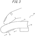
FIG. 3 schematically illustrates the power window switch inFIGS. 2A and 2B in a pushed-down state; -
FIG. 4 schematically illustrates the power window switch inFIGS. 2A and 2B in a pulled-up state; -
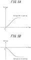
FIGS. 5A and 5B illustrate the relationship between an input operation by the user on an operation interface and a voltage signal output by a piezoelectric element; and -
FIG. 6 is a flowchart illustrating an example of processing by the controller inFIG. 1 . - Depending on the nature of the controlled apparatus that is controlled by input operations to the switch, operability may increase by having the control of the controlled apparatus follow an input operation to the switch in an analog manner. The present disclosure is based on these considerations and aims to provide an input apparatus and input method that can improve operability.
- A switch configured to include a piezoelectric element is an example of an appropriate switch for causing the control of the controlled apparatus to follow an input operation to the switch in an analog manner. Piezoelectric elements are used in apparatuses such as the touch panel apparatus disclosed in patent literature (PTL) 1. An input apparatus according to an embodiment is, for example, configured as a switch that includes a piezoelectric element.
- An embodiment is described below in detail with reference to the drawings.
-
FIG. 1 is a functional block diagram schematically illustrating the configuration of an input apparatus according to a first embodiment. Aninput apparatus 10 includes aninput detector 11, acontroller 12, avibration signal generator 13, avibration output interface 14, and amemory 15. Theinput apparatus 10 functions as a switch for receiving input operations to control a controlledapparatus 20. In other words, on the basis of an input operation to theinput apparatus 10, theinput apparatus 10 outputs a control signal for controlling the controlledapparatus 20. - In the present embodiment, the
input detector 11 and thevibration output interface 14 are configured using onepiezoelectric element 16. Thepiezoelectric element 16 is, for example, attached to anoperation interface 31 for receiving input operations from the user. - The
piezoelectric element 16 is formed by an element that, upon application of an electric signal (voltage), expands and contracts or bends in accordance with the electromechanical coupling coefficient of its constituent material. Piezoelectric elements made of ceramic or crystal elements, for example, may be used. Thepiezoelectric element 16 may be a unimorph, bimorph, or laminated piezoelectric element. Examples of a laminated piezoelectric element include a laminated bimorph element with layers of bimorph and a stacked element having a laminated structure formed by a plurality of dielectric layers composed of, for example, lead zirconate titanate (PZT) and electrode layers disposed between the dielectric layers. Unimorph expands and contracts upon application of an electric signal. Bimorph bends upon application of an electric signal. A stacked laminated piezoelectric element expands and contracts along the lamination direction upon application of an electric signal. In the present embodiment, thepiezoelectric element 16 is described below as being a stacked laminated piezoelectric element. The user performs predetermined input operations on thepiezoelectric element 16. - The
input detector 11 detects input operations to theinput apparatus 10. In other words, theinput detector 11 detects user input operations on theinput apparatus 10, which is a switch. Theinput detector 11 outputs a voltage signal to thecontroller 12 in response to the detected input operation. Theinput detector 11 outputs different voltage signals in accordance with the direction of displacement (expansion or contraction) of thepiezoelectric element 16, for example. Specifically, theinput detector 11 outputs positive and negative (i.e. two types of) voltage signals in accordance with the displacement direction of thepiezoelectric element 16. Theinput detector 11 thus outputs voltage signals of different polarity in accordance with the displacement direction of thepiezoelectric element 16. Theinput detector 11 may further change the amplitude of the voltage signal in accordance with the magnitude of displacement (expansion or contraction) of thepiezoelectric element 16. - The
controller 12 is a processor that controls and manages theinput apparatus 10 overall, including the functional blocks of theinput apparatus 10. Thecontroller 12 is a processor such as a central processing unit (CPU) that executes a program with prescribed control procedures. Such a program may, for example, be stored in thememory 15, on an external storage medium, or the like. - On the basis of a voltage signal acquired from the
input detector 11, thecontroller 12 generates a control signal for controlling the controlledapparatus 20 and outputs the control signal. Specifically, thecontroller 12 performs different control in accordance with the voltage signal acquired from theinput detector 11. The control performed by thecontroller 12 is described in detail below. - On the basis of the voltage signal acquired by the
controller 12 from theinput detector 11, thevibration signal generator 13 generates a vibration signal to be supplied to thevibration output interface 14. For example, thevibration signal generator 13 generates the vibration signal by referring to a plurality of parameter tables, stored in thememory 15, for providing a tactical sensation. The parameter tables include various parameters such as the number of push stages, the number of release stages, a push threshold, a release threshold, a push vibration pattern, a release vibration pattern, and vibration intensity. The signal generated by thevibration signal generator 13 is supplied to thevibration output interface 14 through thecontroller 12. - The
vibration output interface 14 outputs vibration on the basis of the vibration signal input from thevibration signal generator 13 through thecontroller 12. Specifically, thepiezoelectric element 16 vibrates by thevibration output interface 14 causing thepiezoelectric element 16 to expand and contract. Vibration of thevibration output interface 14 provides a tactile sensation to the user, who can learn that a predetermined input operation has been supplied to theinput apparatus 10. - The
memory 15 is, for example, a semiconductor memory or the like. Thememory 15 stores a variety of information, programs for causing theinput apparatus 10 to operate, and the like and also functions as a working memory. For example, thememory 15 stores a parameter table to be referred to when thevibration signal generator 13 generates a vibration signal. - The input operations by the user to the
input apparatus 10 and the control in the controlledapparatus 20 are described below with examples. Here, an example is described in which theinput apparatus 10 is a power window switch of a vehicle, and the controlledapparatus 20 is a power window controlled on the basis of input operations to theinput apparatus 10. The power window includes a driving motor, for example, for raising and lowering the power window in the directions in which the power window opens (opening direction) and closes (closing direction). -
FIGS. 2A and 2B schematically illustrate a power window switch in which theinput apparatus 10 inFIG. 1 is used.FIG. 2A is a top view of thepower window switch 30, andFIG. 2B is a cross-section along the A-A line of thepower window switch 30 inFIG. 2A . Thepower window switch 30 is, for example, provided on the inner side of a door of the vehicle. - The
power window switch 30 includes anoperation interface 31 on which the user performs input operations. As illustrated inFIG. 2B , theoperation interface 31 is supported at one end by abase 32 of a door armrest of the vehicle, for example, and extends in a direction parallel to the door. The direction in which theoperation interface 31 extends is also referred to below as the extending direction. Theoperation interface 31 is, for example, configured by an elastic member that is deformable by an input operation from the user. The user can operate theoperation interface 31 by pushing theoperation interface 31 down from theupper surface 31a side towards thelower surface 31b side and by pulling up atip 31c of theoperation interface 31 with a finger. The state of theoperation interface 31 in which the user is not performing an input operation is referred to below as the non-operation state. - As illustrated in
FIG. 2B , theoperation interface 31 includes thepiezoelectric element 16 stacked on thelower surface 31b along the extending direction of theoperation interface 31. - As illustrated in
FIG. 3 , when the user presses theoperation interface 31 from theupper surface 31a side towards thelower surface 31b side, thetip 31c is pushed down from the non-operation state and theoperation interface 31 bends. Compared to the non-operation state, theoperation interface 31 in this case is lengthened (expanded) in the extending direction of theupper surface 31a and shortened (contracted) in the extending direction of thelower surface 31b by an elastic force. As a result, thepiezoelectric element 16 provided on thelower surface 31b contracts. Theoperation interface 31 bends more as it is pushed down more firmly, causing thepiezoelectric element 16 to contract more. When thepiezoelectric element 16 is in a contracted state, a voltage signal indicating that thepiezoelectric element 16 has contracted is output from theinput detector 11 to thecontroller 12 as information related to the displacement state. - On the other hand, when the user pulls up the
tip 31c of theoperation interface 31 with a finger, thetip 31c is pulled up from the non-operation state and theoperation interface 31 bends, as illustrated inFIG. 4 . Compared to the non-operation state, theoperation interface 31 in this case is shortened (contracted) in the extending direction of theupper surface 31a and lengthened (expanded) in the extending direction of thelower surface 31b by an elastic force. As a result, thepiezoelectric element 16 provided on thelower surface 31b expands. Theoperation interface 31 bends more as it is pulled up more firmly, causing thepiezoelectric element 16 to expand more. When thepiezoelectric element 16 is in an expanded state, a voltage signal indicating that thepiezoelectric element 16 has expanded is output from theinput detector 11 to thecontroller 12 as information related to the displacement state. In this way, theinput detector 11 provides different outputs when thepiezoelectric element 16 expands and when thepiezoelectric element 16 contracts. - Here, the different control that the
controller 12 performs in accordance with the voltage signal acquired from theinput detector 11 is described.FIGS. 5A and 5B illustrate the relationship between the input operation by the user on theoperation interface 31 and the voltage signal output by the piezoelectric element 16 (input detector 11). As an example,FIGS. 5A and 5B illustrate the case of a positive voltage signal being output when thepiezoelectric element 16 contracts. - For example, when the
operation interface 31 is pushed down (while pushing) as illustrated inFIG. 3 , a positive voltage signal indicating that thepiezoelectric element 16 has contracted as a result of a push operation by the user is output from theinput detector 11, as illustrated inFIG. 5A . Theinput detector 11 outputs a higher voltage signal as thepiezoelectric element 16 contracts more. On the other hand, when theoperation interface 31 is pulled up (while pulling) as illustrated inFIG. 4 , a negative voltage signal indicating that thepiezoelectric element 16 has expanded as a result of a pull-up operation by the user is output from theinput detector 11, as illustrated inFIG. 5B . Theinput detector 11 outputs a lower voltage signal as thepiezoelectric element 16 expands more. - On the basis of a voltage signal acquired from the
input detector 11, thecontroller 12 generates a control signal for controlling the power window of the vehicle. When acquiring a positive voltage signal, for example, thecontroller 12 generates a control signal (drive signal) for displacing the power window in the opening direction and outputs the control signal to a drive motor provided in the power window. Thecontroller 12 may, for example, generate a control signal for displacing the power window faster as the absolute value of the acquired voltage is greater. The drive motor of the power window is driven in response to the control signal acquired from thecontroller 12. The power window is displaced in the opening direction by the drive motor being driven. - When acquiring a negative voltage signal, for example, the
controller 12 generates a control signal for displacing the power window in the closing direction and outputs the control signal to the drive motor provided in the power window. Thecontroller 12 may, for example, generate a control signal for displacing the power window faster as the absolute value of the acquired voltage is greater. The drive motor of the power window is driven in response to the control signal acquired from thecontroller 12. The power window is displaced in the closing direction by the drive motor being driven. - In this way, the
controller 12 performs control to open and close the power window, which is the controlledapparatus 20, in accordance with the voltage signal from theinput detector 11. When the voltage signal is input to thecontroller 12, thecontroller 12 may input the vibration signal generated by thevibration signal generator 13 to thevibration output interface 14. Once the vibration signal is input to thevibration output interface 14, thepiezoelectric element 16 vibrates, thereby vibrating theoperation interface 31. Thevibration signal generator 13 may generate vibration signals with different patterns in accordance with the voltage signal from theinput detector 11. As a result, thepiezoelectric element 16 vibrates in different ways in accordance with the voltage signal from theinput detector 11. - Next, processing by the
controller 12 is described.FIG. 6 is a flowchart illustrating an example of processing by thecontroller 12 inFIG. 1 . - First, when the user performs an input operation on the
operation interface 31, theinput detector 11 outputs a voltage signal in accordance with the input operation. Thecontroller 12 acquires the voltage signal output by the input detector 11 (step S101). - Next, the
controller 12 judges whether the voltage signal acquired from theinput detector 11 is a positive voltage signal or a negative voltage signal (step S102). - When it is judged that the voltage signal acquired from the
input detector 11 is a positive voltage signal (step S102: Yes), thecontroller 12 generates a control signal for displacing the power window in the opening direction (step S103). - Conversely, when it is judged that the voltage signal acquired from the
input detector 11 is a negative voltage signal (step S102: No), thecontroller 12 generates a control signal for displacing the power window in the closing direction (step S104). - After generating the control signal in step S103 or step S104, the
controller 12 outputs the generated control signal to the drive motor of the power window (step S105). - In response to the control signal, the drive motor rotates in the positive or reverse direction, for example, to displace the power window in the opening direction or the closing direction.
- In this way, the
controller 12 in theinput apparatus 10 according to the present embodiment performs different control to displace the power window in the opening direction or the closing direction in accordance with positive and negative voltage signals acquired from the piezoelectric element 16 (input detector 11). Therefore, theinput apparatus 10 allows a reduction in the number of input detectors 11 (piezoelectric elements 16) as compared, for example, to the case of providing an input apparatus withdifferent input detectors 11 for different types of control to displace the power window in the opening direction or the closing direction. When controlling a power window as described in the above embodiment by performing two types of control, in the opening direction and the closing direction, theinput apparatus 10 can achieve these two types of power window control using onepiezoelectric element 16. The manufacturing cost of theinput apparatus 10 can be reduced by this reduction in the number of elements. - The
controller 12 changes the output in accordance with the magnitude of displacement of thepiezoelectric element 16. In other words, thecontroller 12 generates a control signal for displacing the power window faster as the amplitude of the voltage signal acquired from theinput detector 11 is greater. Hence, the user can cause control to be executed to open the power window faster by pushing theoperation interface 31 down more firmly and cause control to be executed to close the power window faster by pulling theoperation interface 31 up more firmly. Conversely, the user can cause control to be executed to open the power window more slowly by pushing theoperation interface 31 down more weakly and cause control to be executed to close the power window more slowly by pulling theoperation interface 31 up more weakly. Theinput apparatus 10 allows the opening and closing operation of the power window to follow the input operation to theoperation interface 31 in an analog manner. Therefore, theinput apparatus 10 facilitates the operation of the controlledapparatus 20 in accordance with the user's desire. This makes it easier for the user to make minute adjustments by operating the switch to displace thepiezoelectric element 16 slightly when opening or closing the power window, for example. Theinput apparatus 10 thus improves operability. - The above embodiment is provided as an example, and a variety of modifications and changes are possible. For example, the functions and the like included in the various components and steps may be reordered in any logically consistent way. Furthermore, components or steps may be combined into one or divided.
- For example, the
input apparatus 10 has been described in the above embodiment as being applied to apower window switch 30, but theinput apparatus 10 can be used in other applications. - For example, the
input apparatus 10 can be used as a switch for controlling an electric reclining chair. An electric reclining chair is, for example, provided with a drive motor for reclining and raising the backrest. When using theinput apparatus 10 as a switch for controlling an electric reclining chair, the switch can be structured in the same way as the one inFIGS. 2A and 2B , for example. In this case, when thepiezoelectric element 16 expands due to the user pulling up theoperation interface 31, thecontroller 12 outputs a control signal for reclining the backrest of the reclining chair to the drive motor on the basis of a voltage signal acquired from thepiezoelectric element 16. On the other hand, when thepiezoelectric element 16 contracts due to the user pushing down theoperation interface 31, thecontroller 12 outputs a control signal for raising the backrest of the reclining chair to the drive motor on the basis of a voltage signal acquired from thepiezoelectric element 16. Thecontroller 12 can generate control signals with different reclining speeds in accordance with the magnitude of the absolute value of the voltage signal. Theinput apparatus 10 thereby facilitates the operation of the controlledapparatus 20 in accordance with the user's desire. - Furthermore, the
input apparatus 10 can, for example, be used as a switch for controlling a power seat in which the seat position and the angle of the backrest can be changed. In this case as well, thecontroller 12 generates a control signal for controlling the power seat in the forward/backward or left/right directions, for example, in accordance with the polarity of voltage output by thepiezoelectric element 16 provided in theoperation interface 31. - The
input apparatus 10 can also be used in a variety of applications other than the above example. In particular, theinput apparatus 10 is appropriate as a switch of a controlled apparatus that moves reciprocally in predetermined directions, as in the above example. - In the above embodiment, the
input detector 11 may, for example, change the amplitude of the voltage signal in accordance with the acceleration of displacement (expansion or contraction) of thepiezoelectric element 16. In this case, theinput detector 11 supplies thecontroller 12 with a voltage signal having an amplitude corresponding to acceleration. Thecontroller 12 determines the speed, for example, at which to displace the power window as in the above embodiment in accordance with the supplied voltage signal. - Furthermore, the position at which the
piezoelectric element 16 is disposed in theoperation interface 31 is not limited to thelower surface 31b. Thepiezoelectric element 16 can be disposed at any position allowing expansion and contraction in accordance with operation of theoperation interface 31 by the user. In the example illustrated inFIGS. 2A and 2B , thepiezoelectric element 16 may, for example, be provided on theupper surface 31a or inside theoperation interface 31. -
- 10
- Input apparatus
- 11
- Input detector
- 12
- Controller
- 13
- Vibration signal generator
- 14
- Vibration output interface
- 15
- Memory
- 16
- Piezoelectric element
- 20
- Controlled apparatus
- 30
- Power window switch
- 31
- Operation interface
- 31a
- Upper surface
- 31b
- Lower surface
- 31c
- Tip
- 32
- Base
Claims (5)
- An input apparatus comprising:an operation interface configured to receive an input operation from a user;a piezoelectric element attached to the operation interface; anda controller configured to acquire output based on the input operation to the operation interface from the piezoelectric element and to execute different control with respect to a controlled apparatus in accordance with the output.
- The input apparatus of claim 1, wherein the controller is configured to execute the different control in accordance with a polarity of voltage output from the piezoelectric element.
- The input apparatus of claim 2, wherein the controller is configured to determine a speed of the control with respect to the controlled apparatus in accordance with the magnitude of the voltage.
- The input apparatus of any one of claims 1 to 3, wherein the controller is configured to provide a tactile sensation to the user by causing the piezoelectric element to expand and contract when the controller acquires the output from the piezoelectric element.
- An input method for an input apparatus comprising an operation interface configured to receive an input operation from a user, a piezoelectric element attached to the operation interface, and a controller, the input method comprising:acquiring, using the controller, output based on the input operation to the operation interface from the piezoelectric element; andexecuting different control with respect to a controlled apparatus in accordance with the output.
Applications Claiming Priority (2)
| Application Number | Priority Date | Filing Date | Title |
|---|---|---|---|
| JP2015232191A JP6342875B2 (en) | 2015-11-27 | 2015-11-27 | Input device and input method |
| PCT/JP2016/083115 WO2017090425A1 (en) | 2015-11-27 | 2016-11-08 | Input device and input method |
Publications (3)
| Publication Number | Publication Date |
|---|---|
| EP3382513A1 true EP3382513A1 (en) | 2018-10-03 |
| EP3382513A4 EP3382513A4 (en) | 2019-06-26 |
| EP3382513B1 EP3382513B1 (en) | 2023-09-20 |
Family
ID=58763124
Family Applications (1)
| Application Number | Title | Priority Date | Filing Date |
|---|---|---|---|
| EP16868373.8A Active EP3382513B1 (en) | 2015-11-27 | 2016-11-08 | Input device and input method |
Country Status (4)
| Country | Link |
|---|---|
| US (1) | US11561617B2 (en) |
| EP (1) | EP3382513B1 (en) |
| JP (1) | JP6342875B2 (en) |
| WO (1) | WO2017090425A1 (en) |
Family Cites Families (22)
| Publication number | Priority date | Publication date | Assignee | Title |
|---|---|---|---|---|
| JP2887853B2 (en) * | 1992-01-07 | 1999-05-10 | アルプス電気株式会社 | Switch device |
| JPH09237152A (en) * | 1996-02-29 | 1997-09-09 | Oki Electric Ind Co Ltd | Coordinate input device |
| JPH09244801A (en) * | 1996-03-08 | 1997-09-19 | Copal Co Ltd | Pressure detection type pointing device |
| JP3073658U (en) * | 2000-05-30 | 2000-11-30 | 石原 光晴 | Portable computer input terminal with built-in position detection means |
| JP2002232317A (en) * | 2001-02-07 | 2002-08-16 | Nippon Telegr & Teleph Corp <Ntt> | Haptic communication device |
| JP2003271301A (en) * | 2002-03-15 | 2003-09-26 | Hitachi Ltd | Mobile terminal device |
| JP2004213341A (en) | 2002-12-27 | 2004-07-29 | Matsushita Electric Ind Co Ltd | Cord-shaped pressure sensor input device and planar input device |
| JP2005100917A (en) | 2003-06-23 | 2005-04-14 | Casio Comput Co Ltd | Signal generation device, operation signal generation device, operation input device, camera release device, and electronic camera |
| JP4946763B2 (en) | 2007-10-01 | 2012-06-06 | ブラザー工業株式会社 | Bending detector |
| US8384687B2 (en) * | 2008-08-21 | 2013-02-26 | Denso Corporation | Manipulation input apparatus |
| JP2010147619A (en) * | 2008-12-17 | 2010-07-01 | Nikon Corp | Image control system |
| US8427441B2 (en) * | 2008-12-23 | 2013-04-23 | Research In Motion Limited | Portable electronic device and method of control |
| US8305200B2 (en) * | 2009-12-02 | 2012-11-06 | Analog Devices, Inc. | Reactive networks to reduce acoustic noise and ensure maximum efficiencies in driving piezoelectric elements in haptic applications |
| JP2011215926A (en) * | 2010-03-31 | 2011-10-27 | Fujitsu Ten Ltd | Operation unit |
| JP5452404B2 (en) * | 2010-07-27 | 2014-03-26 | 京セラ株式会社 | Tactile presentation device |
| EP2631745B1 (en) | 2010-10-21 | 2018-08-01 | Kyocera Corporation | Touch panel device |
| EP2696163B1 (en) | 2011-04-08 | 2018-05-23 | Murata Manufacturing Co., Ltd. | Displacement sensor, displacement detecting apparatus, and operation device |
| JP5700253B2 (en) * | 2011-12-27 | 2015-04-15 | アイシン・エィ・ダブリュ株式会社 | Operation input system |
| JP6052704B2 (en) * | 2012-07-10 | 2016-12-27 | カシオ計算機株式会社 | INPUT DEVICE, INPUT OPERATION ANALYSIS METHOD, INPUT OPERATION ANALYSIS PROGRAM |
| WO2015121964A1 (en) * | 2014-02-14 | 2015-08-20 | 富士通株式会社 | Input device |
| US10053036B2 (en) * | 2014-12-31 | 2018-08-21 | Harman International Industries, Incorporated | Shape-changing surface |
| US9971407B2 (en) * | 2015-09-30 | 2018-05-15 | Apple Inc. | Haptic feedback for rotary inputs |
-
2015
- 2015-11-27 JP JP2015232191A patent/JP6342875B2/en active Active
-
2016
- 2016-11-08 EP EP16868373.8A patent/EP3382513B1/en active Active
- 2016-11-08 US US15/777,554 patent/US11561617B2/en active Active
- 2016-11-08 WO PCT/JP2016/083115 patent/WO2017090425A1/en not_active Ceased
Also Published As
| Publication number | Publication date |
|---|---|
| US11561617B2 (en) | 2023-01-24 |
| US20180329496A1 (en) | 2018-11-15 |
| JP2017102493A (en) | 2017-06-08 |
| EP3382513A4 (en) | 2019-06-26 |
| EP3382513B1 (en) | 2023-09-20 |
| JP6342875B2 (en) | 2018-06-13 |
| WO2017090425A1 (en) | 2017-06-01 |
Similar Documents
| Publication | Publication Date | Title |
|---|---|---|
| US9396629B1 (en) | Haptic modules with independently controllable vertical and horizontal mass movements | |
| EP2201620B1 (en) | Electronic device and circuit for providing tactile feedback | |
| CN105074621B (en) | Piezo-actuated virtual buttons for touch surfaces | |
| JP5045577B2 (en) | Robot hand mechanism, robot having robot hand mechanism, and control method of robot hand mechanism | |
| US10482730B2 (en) | Electronic device | |
| CN110609637A (en) | Haptic actuator assembly with spring preload device | |
| CN111670542A (en) | Apparatus and method for generating active haptic feedback | |
| EP4412064A3 (en) | Control device | |
| WO2011024435A1 (en) | Tactile sensation imparting device and control method of tactile sensation imparting device | |
| JP6143179B2 (en) | Operation input device | |
| EP3161588A1 (en) | Multimodal haptic effect system | |
| CN112368670A (en) | Device for generating haptic signals | |
| JP2017130021A (en) | Tactile presentation device | |
| JP7032048B2 (en) | Control device, input system and control method | |
| US11561617B2 (en) | Input apparatus and input method | |
| JP5710214B2 (en) | Input device and control method of input device | |
| JP2016162062A (en) | Haptic feedback device | |
| JP6237927B2 (en) | Tactile presentation device | |
| JP2017219903A (en) | Operation device | |
| JP7106052B2 (en) | Driving device, driving method and operating device for vibration actuator | |
| JP2017224160A (en) | Tactile presentation device | |
| JP6199847B2 (en) | Tactile presentation device | |
| JP6337685B2 (en) | Tactile presentation device | |
| CN110875419A (en) | Reversible actuator, method for manufacturing the same, and apparatus including the same | |
| WO2024039295A1 (en) | A device for receiving a tactile input from a user |
Legal Events
| Date | Code | Title | Description |
|---|---|---|---|
| STAA | Information on the status of an ep patent application or granted ep patent |
Free format text: STATUS: THE INTERNATIONAL PUBLICATION HAS BEEN MADE |
|
| PUAI | Public reference made under article 153(3) epc to a published international application that has entered the european phase |
Free format text: ORIGINAL CODE: 0009012 |
|
| STAA | Information on the status of an ep patent application or granted ep patent |
Free format text: STATUS: REQUEST FOR EXAMINATION WAS MADE |
|
| 17P | Request for examination filed |
Effective date: 20180524 |
|
| AK | Designated contracting states |
Kind code of ref document: A1 Designated state(s): AL AT BE BG CH CY CZ DE DK EE ES FI FR GB GR HR HU IE IS IT LI LT LU LV MC MK MT NL NO PL PT RO RS SE SI SK SM TR |
|
| AX | Request for extension of the european patent |
Extension state: BA ME |
|
| DAV | Request for validation of the european patent (deleted) | ||
| DAX | Request for extension of the european patent (deleted) | ||
| A4 | Supplementary search report drawn up and despatched |
Effective date: 20190523 |
|
| RIC1 | Information provided on ipc code assigned before grant |
Ipc: G06F 3/01 20060101ALI20190517BHEP Ipc: G06F 3/02 20060101ALI20190517BHEP Ipc: G06F 3/0338 20130101AFI20190517BHEP Ipc: H01L 41/04 20060101ALI20190517BHEP |
|
| STAA | Information on the status of an ep patent application or granted ep patent |
Free format text: STATUS: EXAMINATION IS IN PROGRESS |
|
| 17Q | First examination report despatched |
Effective date: 20201202 |
|
| GRAP | Despatch of communication of intention to grant a patent |
Free format text: ORIGINAL CODE: EPIDOSNIGR1 |
|
| STAA | Information on the status of an ep patent application or granted ep patent |
Free format text: STATUS: GRANT OF PATENT IS INTENDED |
|
| RIC1 | Information provided on ipc code assigned before grant |
Ipc: B60K 37/06 20060101ALI20230329BHEP Ipc: B60K 35/00 20060101ALI20230329BHEP Ipc: G06F 3/038 20130101ALI20230329BHEP Ipc: G06F 3/02 20060101ALI20230329BHEP Ipc: G06F 3/01 20060101ALI20230329BHEP Ipc: G06F 3/0338 20130101AFI20230329BHEP |
|
| INTG | Intention to grant announced |
Effective date: 20230414 |
|
| P01 | Opt-out of the competence of the unified patent court (upc) registered |
Effective date: 20230508 |
|
| GRAS | Grant fee paid |
Free format text: ORIGINAL CODE: EPIDOSNIGR3 |
|
| GRAA | (expected) grant |
Free format text: ORIGINAL CODE: 0009210 |
|
| STAA | Information on the status of an ep patent application or granted ep patent |
Free format text: STATUS: THE PATENT HAS BEEN GRANTED |
|
| AK | Designated contracting states |
Kind code of ref document: B1 Designated state(s): AL AT BE BG CH CY CZ DE DK EE ES FI FR GB GR HR HU IE IS IT LI LT LU LV MC MK MT NL NO PL PT RO RS SE SI SK SM TR |
|
| REG | Reference to a national code |
Ref country code: GB Ref legal event code: FG4D |
|
| REG | Reference to a national code |
Ref country code: CH Ref legal event code: EP |
|
| REG | Reference to a national code |
Ref country code: DE Ref legal event code: R096 Ref document number: 602016082935 Country of ref document: DE |
|
| REG | Reference to a national code |
Ref country code: IE Ref legal event code: FG4D |
|
| REG | Reference to a national code |
Ref country code: LT Ref legal event code: MG9D |
|
| PG25 | Lapsed in a contracting state [announced via postgrant information from national office to epo] |
Ref country code: GR Free format text: LAPSE BECAUSE OF FAILURE TO SUBMIT A TRANSLATION OF THE DESCRIPTION OR TO PAY THE FEE WITHIN THE PRESCRIBED TIME-LIMIT Effective date: 20231221 |
|
| REG | Reference to a national code |
Ref country code: NL Ref legal event code: MP Effective date: 20230920 |
|
| PG25 | Lapsed in a contracting state [announced via postgrant information from national office to epo] |
Ref country code: SE Free format text: LAPSE BECAUSE OF FAILURE TO SUBMIT A TRANSLATION OF THE DESCRIPTION OR TO PAY THE FEE WITHIN THE PRESCRIBED TIME-LIMIT Effective date: 20230920 Ref country code: RS Free format text: LAPSE BECAUSE OF FAILURE TO SUBMIT A TRANSLATION OF THE DESCRIPTION OR TO PAY THE FEE WITHIN THE PRESCRIBED TIME-LIMIT Effective date: 20230920 Ref country code: NO Free format text: LAPSE BECAUSE OF FAILURE TO SUBMIT A TRANSLATION OF THE DESCRIPTION OR TO PAY THE FEE WITHIN THE PRESCRIBED TIME-LIMIT Effective date: 20231220 Ref country code: LV Free format text: LAPSE BECAUSE OF FAILURE TO SUBMIT A TRANSLATION OF THE DESCRIPTION OR TO PAY THE FEE WITHIN THE PRESCRIBED TIME-LIMIT Effective date: 20230920 Ref country code: LT Free format text: LAPSE BECAUSE OF FAILURE TO SUBMIT A TRANSLATION OF THE DESCRIPTION OR TO PAY THE FEE WITHIN THE PRESCRIBED TIME-LIMIT Effective date: 20230920 Ref country code: HR Free format text: LAPSE BECAUSE OF FAILURE TO SUBMIT A TRANSLATION OF THE DESCRIPTION OR TO PAY THE FEE WITHIN THE PRESCRIBED TIME-LIMIT Effective date: 20230920 Ref country code: GR Free format text: LAPSE BECAUSE OF FAILURE TO SUBMIT A TRANSLATION OF THE DESCRIPTION OR TO PAY THE FEE WITHIN THE PRESCRIBED TIME-LIMIT Effective date: 20231221 Ref country code: FI Free format text: LAPSE BECAUSE OF FAILURE TO SUBMIT A TRANSLATION OF THE DESCRIPTION OR TO PAY THE FEE WITHIN THE PRESCRIBED TIME-LIMIT Effective date: 20230920 |
|
| REG | Reference to a national code |
Ref country code: AT Ref legal event code: MK05 Ref document number: 1613900 Country of ref document: AT Kind code of ref document: T Effective date: 20230920 |
|
| PG25 | Lapsed in a contracting state [announced via postgrant information from national office to epo] |
Ref country code: NL Free format text: LAPSE BECAUSE OF FAILURE TO SUBMIT A TRANSLATION OF THE DESCRIPTION OR TO PAY THE FEE WITHIN THE PRESCRIBED TIME-LIMIT Effective date: 20230920 |
|
| PG25 | Lapsed in a contracting state [announced via postgrant information from national office to epo] |
Ref country code: IS Free format text: LAPSE BECAUSE OF FAILURE TO SUBMIT A TRANSLATION OF THE DESCRIPTION OR TO PAY THE FEE WITHIN THE PRESCRIBED TIME-LIMIT Effective date: 20240120 |
|
| PG25 | Lapsed in a contracting state [announced via postgrant information from national office to epo] |
Ref country code: AT Free format text: LAPSE BECAUSE OF FAILURE TO SUBMIT A TRANSLATION OF THE DESCRIPTION OR TO PAY THE FEE WITHIN THE PRESCRIBED TIME-LIMIT Effective date: 20230920 |
|
| PG25 | Lapsed in a contracting state [announced via postgrant information from national office to epo] |
Ref country code: ES Free format text: LAPSE BECAUSE OF FAILURE TO SUBMIT A TRANSLATION OF THE DESCRIPTION OR TO PAY THE FEE WITHIN THE PRESCRIBED TIME-LIMIT Effective date: 20230920 |
|
| PG25 | Lapsed in a contracting state [announced via postgrant information from national office to epo] |
Ref country code: SM Free format text: LAPSE BECAUSE OF FAILURE TO SUBMIT A TRANSLATION OF THE DESCRIPTION OR TO PAY THE FEE WITHIN THE PRESCRIBED TIME-LIMIT Effective date: 20230920 Ref country code: RO Free format text: LAPSE BECAUSE OF FAILURE TO SUBMIT A TRANSLATION OF THE DESCRIPTION OR TO PAY THE FEE WITHIN THE PRESCRIBED TIME-LIMIT Effective date: 20230920 Ref country code: IS Free format text: LAPSE BECAUSE OF FAILURE TO SUBMIT A TRANSLATION OF THE DESCRIPTION OR TO PAY THE FEE WITHIN THE PRESCRIBED TIME-LIMIT Effective date: 20240120 Ref country code: ES Free format text: LAPSE BECAUSE OF FAILURE TO SUBMIT A TRANSLATION OF THE DESCRIPTION OR TO PAY THE FEE WITHIN THE PRESCRIBED TIME-LIMIT Effective date: 20230920 Ref country code: EE Free format text: LAPSE BECAUSE OF FAILURE TO SUBMIT A TRANSLATION OF THE DESCRIPTION OR TO PAY THE FEE WITHIN THE PRESCRIBED TIME-LIMIT Effective date: 20230920 Ref country code: CZ Free format text: LAPSE BECAUSE OF FAILURE TO SUBMIT A TRANSLATION OF THE DESCRIPTION OR TO PAY THE FEE WITHIN THE PRESCRIBED TIME-LIMIT Effective date: 20230920 Ref country code: AT Free format text: LAPSE BECAUSE OF FAILURE TO SUBMIT A TRANSLATION OF THE DESCRIPTION OR TO PAY THE FEE WITHIN THE PRESCRIBED TIME-LIMIT Effective date: 20230920 Ref country code: SK Free format text: LAPSE BECAUSE OF FAILURE TO SUBMIT A TRANSLATION OF THE DESCRIPTION OR TO PAY THE FEE WITHIN THE PRESCRIBED TIME-LIMIT Effective date: 20230920 Ref country code: PT Free format text: LAPSE BECAUSE OF FAILURE TO SUBMIT A TRANSLATION OF THE DESCRIPTION OR TO PAY THE FEE WITHIN THE PRESCRIBED TIME-LIMIT Effective date: 20240122 |
|
| PG25 | Lapsed in a contracting state [announced via postgrant information from national office to epo] |
Ref country code: PL Free format text: LAPSE BECAUSE OF FAILURE TO SUBMIT A TRANSLATION OF THE DESCRIPTION OR TO PAY THE FEE WITHIN THE PRESCRIBED TIME-LIMIT Effective date: 20230920 Ref country code: IT Free format text: LAPSE BECAUSE OF FAILURE TO SUBMIT A TRANSLATION OF THE DESCRIPTION OR TO PAY THE FEE WITHIN THE PRESCRIBED TIME-LIMIT Effective date: 20230920 |
|
| REG | Reference to a national code |
Ref country code: DE Ref legal event code: R097 Ref document number: 602016082935 Country of ref document: DE |
|
| REG | Reference to a national code |
Ref country code: CH Ref legal event code: PL |
|
| PG25 | Lapsed in a contracting state [announced via postgrant information from national office to epo] |
Ref country code: MC Free format text: LAPSE BECAUSE OF FAILURE TO SUBMIT A TRANSLATION OF THE DESCRIPTION OR TO PAY THE FEE WITHIN THE PRESCRIBED TIME-LIMIT Effective date: 20230920 |
|
| PG25 | Lapsed in a contracting state [announced via postgrant information from national office to epo] |
Ref country code: DK Free format text: LAPSE BECAUSE OF FAILURE TO SUBMIT A TRANSLATION OF THE DESCRIPTION OR TO PAY THE FEE WITHIN THE PRESCRIBED TIME-LIMIT Effective date: 20230920 |
|
| PG25 | Lapsed in a contracting state [announced via postgrant information from national office to epo] |
Ref country code: LU Free format text: LAPSE BECAUSE OF NON-PAYMENT OF DUE FEES Effective date: 20231108 |
|
| PG25 | Lapsed in a contracting state [announced via postgrant information from national office to epo] |
Ref country code: CH Free format text: LAPSE BECAUSE OF NON-PAYMENT OF DUE FEES Effective date: 20231130 |
|
| PLBE | No opposition filed within time limit |
Free format text: ORIGINAL CODE: 0009261 |
|
| STAA | Information on the status of an ep patent application or granted ep patent |
Free format text: STATUS: NO OPPOSITION FILED WITHIN TIME LIMIT |
|
| PG25 | Lapsed in a contracting state [announced via postgrant information from national office to epo] |
Ref country code: MC Free format text: LAPSE BECAUSE OF FAILURE TO SUBMIT A TRANSLATION OF THE DESCRIPTION OR TO PAY THE FEE WITHIN THE PRESCRIBED TIME-LIMIT Effective date: 20230920 Ref country code: LU Free format text: LAPSE BECAUSE OF NON-PAYMENT OF DUE FEES Effective date: 20231108 Ref country code: DK Free format text: LAPSE BECAUSE OF FAILURE TO SUBMIT A TRANSLATION OF THE DESCRIPTION OR TO PAY THE FEE WITHIN THE PRESCRIBED TIME-LIMIT Effective date: 20230920 Ref country code: CH Free format text: LAPSE BECAUSE OF NON-PAYMENT OF DUE FEES Effective date: 20231130 |
|
| REG | Reference to a national code |
Ref country code: BE Ref legal event code: MM Effective date: 20231130 |
|
| 26N | No opposition filed |
Effective date: 20240621 |
|
| REG | Reference to a national code |
Ref country code: IE Ref legal event code: MM4A |
|
| PG25 | Lapsed in a contracting state [announced via postgrant information from national office to epo] |
Ref country code: IE Free format text: LAPSE BECAUSE OF NON-PAYMENT OF DUE FEES Effective date: 20231108 |
|
| PG25 | Lapsed in a contracting state [announced via postgrant information from national office to epo] |
Ref country code: BE Free format text: LAPSE BECAUSE OF NON-PAYMENT OF DUE FEES Effective date: 20231130 |
|
| PG25 | Lapsed in a contracting state [announced via postgrant information from national office to epo] |
Ref country code: SI Free format text: LAPSE BECAUSE OF FAILURE TO SUBMIT A TRANSLATION OF THE DESCRIPTION OR TO PAY THE FEE WITHIN THE PRESCRIBED TIME-LIMIT Effective date: 20230920 |
|
| PG25 | Lapsed in a contracting state [announced via postgrant information from national office to epo] |
Ref country code: SI Free format text: LAPSE BECAUSE OF FAILURE TO SUBMIT A TRANSLATION OF THE DESCRIPTION OR TO PAY THE FEE WITHIN THE PRESCRIBED TIME-LIMIT Effective date: 20230920 Ref country code: IE Free format text: LAPSE BECAUSE OF NON-PAYMENT OF DUE FEES Effective date: 20231108 Ref country code: BE Free format text: LAPSE BECAUSE OF NON-PAYMENT OF DUE FEES Effective date: 20231130 |
|
| PG25 | Lapsed in a contracting state [announced via postgrant information from national office to epo] |
Ref country code: BG Free format text: LAPSE BECAUSE OF FAILURE TO SUBMIT A TRANSLATION OF THE DESCRIPTION OR TO PAY THE FEE WITHIN THE PRESCRIBED TIME-LIMIT Effective date: 20230920 |
|
| PG25 | Lapsed in a contracting state [announced via postgrant information from national office to epo] |
Ref country code: BG Free format text: LAPSE BECAUSE OF FAILURE TO SUBMIT A TRANSLATION OF THE DESCRIPTION OR TO PAY THE FEE WITHIN THE PRESCRIBED TIME-LIMIT Effective date: 20230920 |
|
| PG25 | Lapsed in a contracting state [announced via postgrant information from national office to epo] |
Ref country code: CY Free format text: LAPSE BECAUSE OF FAILURE TO SUBMIT A TRANSLATION OF THE DESCRIPTION OR TO PAY THE FEE WITHIN THE PRESCRIBED TIME-LIMIT; INVALID AB INITIO Effective date: 20161108 |
|
| PG25 | Lapsed in a contracting state [announced via postgrant information from national office to epo] |
Ref country code: HU Free format text: LAPSE BECAUSE OF FAILURE TO SUBMIT A TRANSLATION OF THE DESCRIPTION OR TO PAY THE FEE WITHIN THE PRESCRIBED TIME-LIMIT; INVALID AB INITIO Effective date: 20161108 |
|
| PGFP | Annual fee paid to national office [announced via postgrant information from national office to epo] |
Ref country code: FR Payment date: 20250930 Year of fee payment: 10 |
|
| PG25 | Lapsed in a contracting state [announced via postgrant information from national office to epo] |
Ref country code: TR Free format text: LAPSE BECAUSE OF FAILURE TO SUBMIT A TRANSLATION OF THE DESCRIPTION OR TO PAY THE FEE WITHIN THE PRESCRIBED TIME-LIMIT Effective date: 20230920 |
|
| PGFP | Annual fee paid to national office [announced via postgrant information from national office to epo] |
Ref country code: DE Payment date: 20250930 Year of fee payment: 10 |
|
| PGFP | Annual fee paid to national office [announced via postgrant information from national office to epo] |
Ref country code: GB Payment date: 20251001 Year of fee payment: 10 |