EP3382456A1 - Image reading apparatus and image forming system - Google Patents
Image reading apparatus and image forming system Download PDFInfo
- Publication number
- EP3382456A1 EP3382456A1 EP18160046.1A EP18160046A EP3382456A1 EP 3382456 A1 EP3382456 A1 EP 3382456A1 EP 18160046 A EP18160046 A EP 18160046A EP 3382456 A1 EP3382456 A1 EP 3382456A1
- Authority
- EP
- European Patent Office
- Prior art keywords
- reader
- image
- conveying
- conveyer
- sheet
- Prior art date
- Legal status (The legal status is an assumption and is not a legal conclusion. Google has not performed a legal analysis and makes no representation as to the accuracy of the status listed.)
- Withdrawn
Links
- 239000000463 material Substances 0.000 claims abstract description 13
- 238000006073 displacement reaction Methods 0.000 claims description 10
- 239000002184 metal Substances 0.000 claims description 7
- 229910052751 metal Inorganic materials 0.000 claims description 7
- 239000003086 colorant Substances 0.000 description 11
- 238000012937 correction Methods 0.000 description 11
- 238000012546 transfer Methods 0.000 description 9
- 230000003287 optical effect Effects 0.000 description 8
- 238000012545 processing Methods 0.000 description 6
- 238000010586 diagram Methods 0.000 description 5
- 108091008695 photoreceptors Proteins 0.000 description 5
- 230000001902 propagating effect Effects 0.000 description 5
- 238000006243 chemical reaction Methods 0.000 description 3
- 238000000034 method Methods 0.000 description 3
- 230000008569 process Effects 0.000 description 3
- 230000004044 response Effects 0.000 description 3
- 230000000694 effects Effects 0.000 description 2
- 230000007246 mechanism Effects 0.000 description 2
- 238000012986 modification Methods 0.000 description 2
- 229910000831 Steel Inorganic materials 0.000 description 1
- 230000002411 adverse Effects 0.000 description 1
- 230000002238 attenuated effect Effects 0.000 description 1
- 238000003705 background correction Methods 0.000 description 1
- 230000015572 biosynthetic process Effects 0.000 description 1
- 238000004891 communication Methods 0.000 description 1
- 238000001816 cooling Methods 0.000 description 1
- 238000009792 diffusion process Methods 0.000 description 1
- 239000011521 glass Substances 0.000 description 1
- 229910052736 halogen Inorganic materials 0.000 description 1
- 150000002367 halogens Chemical class 0.000 description 1
- 239000004973 liquid crystal related substance Substances 0.000 description 1
- 239000011159 matrix material Substances 0.000 description 1
- 230000004048 modification Effects 0.000 description 1
- 238000012856 packing Methods 0.000 description 1
- 238000004080 punching Methods 0.000 description 1
- 238000003908 quality control method Methods 0.000 description 1
- 230000009467 reduction Effects 0.000 description 1
- 239000011347 resin Substances 0.000 description 1
- 229920005989 resin Polymers 0.000 description 1
- 229910001220 stainless steel Inorganic materials 0.000 description 1
- 239000010935 stainless steel Substances 0.000 description 1
- 239000010959 steel Substances 0.000 description 1
Images


Classifications
-
- H—ELECTRICITY
- H04—ELECTRIC COMMUNICATION TECHNIQUE
- H04N—PICTORIAL COMMUNICATION, e.g. TELEVISION
- H04N1/00—Scanning, transmission or reproduction of documents or the like, e.g. facsimile transmission; Details thereof
- H04N1/00795—Reading arrangements
-
- H—ELECTRICITY
- H04—ELECTRIC COMMUNICATION TECHNIQUE
- H04N—PICTORIAL COMMUNICATION, e.g. TELEVISION
- H04N1/00—Scanning, transmission or reproduction of documents or the like, e.g. facsimile transmission; Details thereof
- H04N1/00519—Constructional details not otherwise provided for, e.g. housings, covers
- H04N1/00549—Counter-measures for mechanical vibration not otherwise provided for
-
- B—PERFORMING OPERATIONS; TRANSPORTING
- B65—CONVEYING; PACKING; STORING; HANDLING THIN OR FILAMENTARY MATERIAL
- B65H—HANDLING THIN OR FILAMENTARY MATERIAL, e.g. SHEETS, WEBS, CABLES
- B65H5/00—Feeding articles separated from piles; Feeding articles to machines
- B65H5/06—Feeding articles separated from piles; Feeding articles to machines by rollers or balls, e.g. between rollers
- B65H5/062—Feeding articles separated from piles; Feeding articles to machines by rollers or balls, e.g. between rollers between rollers or balls
-
- G—PHYSICS
- G03—PHOTOGRAPHY; CINEMATOGRAPHY; ANALOGOUS TECHNIQUES USING WAVES OTHER THAN OPTICAL WAVES; ELECTROGRAPHY; HOLOGRAPHY
- G03G—ELECTROGRAPHY; ELECTROPHOTOGRAPHY; MAGNETOGRAPHY
- G03G15/00—Apparatus for electrographic processes using a charge pattern
- G03G15/50—Machine control of apparatus for electrographic processes using a charge pattern, e.g. regulating differents parts of the machine, multimode copiers, microprocessor control
- G03G15/5025—Machine control of apparatus for electrographic processes using a charge pattern, e.g. regulating differents parts of the machine, multimode copiers, microprocessor control by measuring the original characteristics, e.g. contrast, density
-
- G—PHYSICS
- G03—PHOTOGRAPHY; CINEMATOGRAPHY; ANALOGOUS TECHNIQUES USING WAVES OTHER THAN OPTICAL WAVES; ELECTROGRAPHY; HOLOGRAPHY
- G03G—ELECTROGRAPHY; ELECTROPHOTOGRAPHY; MAGNETOGRAPHY
- G03G15/00—Apparatus for electrographic processes using a charge pattern
- G03G15/50—Machine control of apparatus for electrographic processes using a charge pattern, e.g. regulating differents parts of the machine, multimode copiers, microprocessor control
- G03G15/5062—Machine control of apparatus for electrographic processes using a charge pattern, e.g. regulating differents parts of the machine, multimode copiers, microprocessor control by measuring the characteristics of an image on the copy material
-
- G—PHYSICS
- G03—PHOTOGRAPHY; CINEMATOGRAPHY; ANALOGOUS TECHNIQUES USING WAVES OTHER THAN OPTICAL WAVES; ELECTROGRAPHY; HOLOGRAPHY
- G03G—ELECTROGRAPHY; ELECTROPHOTOGRAPHY; MAGNETOGRAPHY
- G03G15/00—Apparatus for electrographic processes using a charge pattern
- G03G15/65—Apparatus which relate to the handling of copy material
- G03G15/6529—Transporting
-
- H—ELECTRICITY
- H04—ELECTRIC COMMUNICATION TECHNIQUE
- H04N—PICTORIAL COMMUNICATION, e.g. TELEVISION
- H04N1/00—Scanning, transmission or reproduction of documents or the like, e.g. facsimile transmission; Details thereof
- H04N1/00519—Constructional details not otherwise provided for, e.g. housings, covers
-
- H—ELECTRICITY
- H04—ELECTRIC COMMUNICATION TECHNIQUE
- H04N—PICTORIAL COMMUNICATION, e.g. TELEVISION
- H04N1/00—Scanning, transmission or reproduction of documents or the like, e.g. facsimile transmission; Details thereof
- H04N1/00519—Constructional details not otherwise provided for, e.g. housings, covers
- H04N1/00559—Mounting or support of components or elements
-
- H—ELECTRICITY
- H04—ELECTRIC COMMUNICATION TECHNIQUE
- H04N—PICTORIAL COMMUNICATION, e.g. TELEVISION
- H04N1/00—Scanning, transmission or reproduction of documents or the like, e.g. facsimile transmission; Details thereof
- H04N1/00567—Handling of original or reproduction media, e.g. cutting, separating, stacking
- H04N1/0057—Conveying sheets before or after scanning
- H04N1/00599—Using specific components
-
- H—ELECTRICITY
- H04—ELECTRIC COMMUNICATION TECHNIQUE
- H04N—PICTORIAL COMMUNICATION, e.g. TELEVISION
- H04N1/00—Scanning, transmission or reproduction of documents or the like, e.g. facsimile transmission; Details thereof
- H04N1/04—Scanning arrangements, i.e. arrangements for the displacement of active reading or reproducing elements relative to the original or reproducing medium, or vice versa
-
- H—ELECTRICITY
- H04—ELECTRIC COMMUNICATION TECHNIQUE
- H04N—PICTORIAL COMMUNICATION, e.g. TELEVISION
- H04N1/00—Scanning, transmission or reproduction of documents or the like, e.g. facsimile transmission; Details thereof
- H04N1/04—Scanning arrangements, i.e. arrangements for the displacement of active reading or reproducing elements relative to the original or reproducing medium, or vice versa
- H04N1/12—Scanning arrangements, i.e. arrangements for the displacement of active reading or reproducing elements relative to the original or reproducing medium, or vice versa using the sheet-feed movement or the medium-advance or the drum-rotation movement as the slow scanning component, e.g. arrangements for the main-scanning
- H04N1/121—Feeding arrangements
- H04N1/123—Using a dedicated sheet guide element
-
- B—PERFORMING OPERATIONS; TRANSPORTING
- B65—CONVEYING; PACKING; STORING; HANDLING THIN OR FILAMENTARY MATERIAL
- B65H—HANDLING THIN OR FILAMENTARY MATERIAL, e.g. SHEETS, WEBS, CABLES
- B65H2801/00—Application field
- B65H2801/03—Image reproduction devices
- B65H2801/06—Office-type machines, e.g. photocopiers
-
- G—PHYSICS
- G03—PHOTOGRAPHY; CINEMATOGRAPHY; ANALOGOUS TECHNIQUES USING WAVES OTHER THAN OPTICAL WAVES; ELECTROGRAPHY; HOLOGRAPHY
- G03G—ELECTROGRAPHY; ELECTROPHOTOGRAPHY; MAGNETOGRAPHY
- G03G21/00—Arrangements not provided for by groups G03G13/00 - G03G19/00, e.g. cleaning, elimination of residual charge
- G03G21/16—Mechanical means for facilitating the maintenance of the apparatus, e.g. modular arrangements
- G03G21/1661—Mechanical means for facilitating the maintenance of the apparatus, e.g. modular arrangements means for handling parts of the apparatus in the apparatus
- G03G21/1695—Mechanical means for facilitating the maintenance of the apparatus, e.g. modular arrangements means for handling parts of the apparatus in the apparatus for paper transport
-
- G—PHYSICS
- G03—PHOTOGRAPHY; CINEMATOGRAPHY; ANALOGOUS TECHNIQUES USING WAVES OTHER THAN OPTICAL WAVES; ELECTROGRAPHY; HOLOGRAPHY
- G03G—ELECTROGRAPHY; ELECTROPHOTOGRAPHY; MAGNETOGRAPHY
- G03G2215/00—Apparatus for electrophotographic processes
- G03G2215/00025—Machine control, e.g. regulating different parts of the machine
- G03G2215/00029—Image density detection
- G03G2215/00067—Image density detection on recording medium
-
- H—ELECTRICITY
- H04—ELECTRIC COMMUNICATION TECHNIQUE
- H04N—PICTORIAL COMMUNICATION, e.g. TELEVISION
- H04N1/00—Scanning, transmission or reproduction of documents or the like, e.g. facsimile transmission; Details thereof
- H04N1/46—Colour picture communication systems
- H04N1/56—Processing of colour picture signals
- H04N1/60—Colour correction or control
- H04N1/6016—Conversion to subtractive colour signals
- H04N1/6019—Conversion to subtractive colour signals using look-up tables
Definitions
- the present invention relates to an image reading apparatus and an image forming system including the image reading apparatus.
- a typical electrophotographic image forming apparatus forms a reference image for image quality control on a sheet, reads the reference image with a reader, and modifies the conditions for forming images in accordance with the read values acquired through reading of the reference image, to achieve uniform image quality.
- the reader is provided with an image sensor (charged coupled device (CCD)), a lighting unit (light emitting diode (LED)) illuminating the sheet, and an optical system (including mirrors and a lens) for focusing the light incident on the sheet from the lighting unit on the image sensor.
- CCD charge coupled device
- LED light emitting diode
- optical system including mirrors and a lens
- Vibration of the image sensor or the mirrors of the reader causes a wavy read image or a shift in the reading position, leading to inaccurate reading of the image on the sheet.
- Vibration sources of the reader include 1) collision of the leading edge of a sheet with conveying guides or other components; 2) impact of a sheet entering conveying rollers or impact of a sheet ejected from the conveying rollers; 3) a motor driving the conveying rollers; and 4) a fan motor for cooling disposed in the apparatus.
- a typical reader based on an optical reduction system focuses an image on an image sensor, such as a CCD, by reflecting the optical axis at a mirror, to achieved compatibility between a light path having a satisfactory length and reduced dimensions of the reader.
- the length of the mirror is determined based on the width of the sheet to be read.
- the mirror should be fixed at a position outside the reading region. Thus, the two edges of the mirror are usually supported on a panel.
- a possible configuration is the support of the mirror in the central area of the back face.
- such a configuration causes distortion of the mirror and thus has an adverse effect on the image to be read.
- An image reading apparatus should be provided with components for conveying sheets, such as conveying rollers conveying the sheets, a driving motor driving the conveying motors, and conveying guides guiding the sheets being conveyed.
- the apparatus includes a housing of a reader (scanner) fixed to the apparatus with a packing.
- a conveying system including sheet conveying components is directly placed on a reader.
- vibration occurs due to various factors, such as the vibration of the driving motor, the vibration of gears and pulleys transmitting the rotation of the driving motor to the conveying rollers, the rotational vibration of the conveying rollers, and collision of the sheet with the conveying guides.
- An object of the present invention which has been conceived in light of the circumstances described above, is to provide an image reading apparatus that accurately reads an image on a sheet and an image forming system including the image reading apparatus.
- an image reading apparatus includes:
- the horizontal direction in Fig. 1 corresponds to the X direction
- the vertical direction corresponds to the Z direction
- a direction orthogonal to the X and Z directions or the front-back direction corresponds to the Y direction.
- the image forming system G includes a print controller g1, a sheet feeder g2, a main unit g3, an image reading apparatus g4, and a finishing apparatus g5.
- the print controller g1 receives page description language (PDL) data from a computer terminal via a network and rasterizes the PDL data into bitmap image data.
- PDL page description language
- the print controller g1 generates image data for each of the colors cyan (C), magenta (M), yellow (Y), and black (K) and outputs the image data to the main unit g3.
- the sheet feeder g2 includes large-volume feeder trays.
- the sheet feeder g2 conveys sheets from a sheet feeder tray to the main unit g3 under an instruction from the main unit g3.
- An image forming unit 8 of the main unit g3 forms an image on a sheet on the basis of image data of an original document D read by a scanner 6 or image data generated by the print controller g1.
- the main unit g3 conveys the sheet after the formation of the image to the image reading apparatus g4.
- a reader 11 of the reading apparatus g4 reads a reference image (providing a reference for, for example, color, tone correction, line width, color resist, and/or front/back alignment) on a sheet and outputs the read image data to a hardware processor 1.
- the image reading apparatus g4 conveys the sheet having the image read by the reader 11 to the finishing apparatus g5.
- the finishing apparatus g5 carries out post-treatment on the sheet sent from the image reading apparatus g4 and ejects the post-treated sheet.
- Examples of the post-treatment includes, stapling, punching, folding, and bookbinding.
- the post-treatment is not essential and thus the finishing apparatus g5 carries out the post-treatment only after an instruction from the main unit g3. If the post-treatment is not instructed, the finishing apparatus g5 ejects the sheet without post-treatment.
- the main unit g3 includes, a hardware processor 1, a memory 2, an operation interface 3, a display 4, a communicator 5, an automatic sheet feeder 61, a scanner 6, an image processor 7, an image forming unit 8, a straightener 9, and sheet feeder trays g31.
- the hardware processor 1 includes a central processing unit (CPU) and a random access memory (RAM).
- the hardware processor 1 reads programs stored in the memory 2 and controls the components of the image forming system G in accordance with these programs.
- the hardware processor 1 feeds a sheet from the sheet feeder g2 or one of the sheet feeder tray g31 in response to an instruction of a job setting.
- the hardware processor 1 allows the image processor 7 to correct and process the image data and the image forming unit 8 to form an image.
- the hardware processor 1 instructs the finishing apparatus g5 to carry out the post-treatment.
- the memory 2 stores programs and files readable by the hardware processor 1.
- the memory 2 may be a storage medium, such as a hard disk or a read only memory (ROM).
- the memory 2 stores reference image data for adjustment of image quality.
- the operation interface 3 includes a touch panel integrated with operating keys and the display 4 and outputs operating signals corresponding to operations of these components to the hardware processor 1. A user can operate the operation interface 3 to input instructions on modification of the job settings and processing.
- the display 4 may be a liquid crystal display (LCD) and displays an operating menu and other images in accordance with instructions from the hardware processor 1.
- LCD liquid crystal display
- the communicator 5 establishes communication with another computer, such as a server or another image forming system, via a network under an instruction from the hardware processor 1.
- another computer such as a server or another image forming system
- the automatic sheet feeder 61 includes a sheet tray for placing an original document D, a mechanism for conveying the original document D, and conveying rollers.
- the automatic sheet feeder 61 conveys the original document D to a predetermined conveying path.
- the scanner 6 includes an optical system including a light source and reflection mirrors.
- the scanner 6 reads the image on the original document D conveyed along the predetermined conveying path or an original document D placed on a glass platen, generates an image data item for each of the colors red (R), green (G), and blue (B), and outputs the generated image data items to the image processor 7.
- the image processor 7 corrects the image data from the scanner 6 or the print hardware processor g1, processes the corrected image data, and outputs the processed image data to the image forming unit 8.
- the image processor 7 includes a color converter 71, a tone corrector 72, and a halftone processor 73.
- the color converter 71 conducts color conversion of the image data items of the colors R, G, and B from the scanner 6 and outputs image data of the colors C, M, Y, and K.
- the color converter 71 may conduct color conversion of the image data items of the colors C, M, Y, and K from the print hardware processor g1 for color correction, and output the color-corrected image data of the colors C, M, Y, and K.
- the color converter 71 retrieves a lookup table (LUT) storing the color-converted tone values of the colors C, M, Y, and K in relation to the tones values of the colors R, G, and B.
- LUT lookup table
- the color converter 71 retrieves an LUT storing the color-corrected tone values of the colors C, M, Y, and K in relation to the tone values of the colors C, M, Y, and K.
- the tone corrector 72 corrects the tone of the image data output from the color converter 71 or the print hardware processor g1.
- the tone corrector 72 retrieves an LUT storing correction values in relation to tone values so as to match the tone properties of the image with target tone properties.
- the tone corrector 72 retrieves correction values corresponding to the tone values of the pixels in the image data, from the LUT for tone correction, and outputs image data consisting of the correction values.
- the halftone processor 73 conducts halftone processing on the image data from the tone corrector 72. Examples of the halftone processing includes screen processing with a dither matrix and error diffusion.
- the halftone processor 73 outputs the image data after the halftone processing to the image forming unit 8.
- the image forming unit 8 forms an image on a sheet on the basis of the image data from the image processor 7.
- the image forming unit 8 is provided with four sets of exposing units 81, photoreceptors 82, and developing units 83 for the respective colors C, M, Y, and K.
- the image forming unit 8 includes an intermediate transfer belt 84, secondary transfer rollers 85, and a fixing unit 86.
- Each exposing unit 81 includes laser diodes (LDs) or light emitting devices.
- the exposing unit 81 drives the LDs on the basis of the image data and illuminates the corresponding charged photoreceptor 82 with a laser beam for exposure.
- the relevant developing unit 83 feeds toner onto the photoreceptor 82 with a charged developer roller and develops an electrostatic latent image in response to the exposure on the photoreceptor 82.
- the four images formed with the respective four color toners on the respective four photoreceptors 82 are sequentially transferred to the intermediate transfer belt 84.
- the intermediate transfer belt 84 is an endless belt wound around several rollers. The intermediate transfer belt 84 rotates in response to the rotation of the rollers.
- the secondary transfer rollers 85 transfer the color image from the intermediate transfer belt 84 to the sheet fed from the sheet feeder g2 or the sheet feeder tray g31.
- the fixing unit 86 applies heat and pressure to the sheet to fix the color image to the sheet.
- the straightener 9 corrects deformation of the sheet due to the fixing to flatten the face of the sheet.
- the sheet readily deforms in the fixing process and should be flattened before reading of the reference image.
- the straightener 9 is disposed between the fixing unit 86 and the reader 11 in the conveying direction of the sheet, as illustrated in Fig. 1 .
- the image reading apparatus g4 includes a reader 11, a corrector 12, a sheet conveyer 13, and a cooler 14.
- the reader 11 reads the image formed on the sheet being conveyed along a conveying path R1 by the sheet conveyer 13, at a predetermined reading position.
- the reader 11 includes a lighting unit 111, an optical system 112, and a CCD 113.
- the lighting unit 111, the optical system 112, and the CCD 113 are fixed to the interior of the housing of the reader 11.
- the lighting unit 111 includes a light source, such as an LED or a halogen lamp, and illuminates the sheet conveyed by conveying rollers 131, at the reading position of the reader 11.
- a light source such as an LED or a halogen lamp
- the optical system 112 includes mirrors 112a (five according to this embodiment) and a lens 112b.
- the optical system 112 focuses the light from the lighting unit 111 incident on the sheet (the image at the reading position), on the CCD 113.
- the CCD 113 reads the image formed on the sheet at the predetermined reading position.
- the CCD 113 is a color line sensor that can read the entire length of the sheet in the width or Y direction.
- the reader 11 which has the configuration described above, can sequentially read the image formed on the sheet across the entire width as the sheet passes the reading position.
- the reader 11 reads a reference image (providing a reference for, for example, color, tone correction, line width, color resist, and/or front/back alignment) formed on a sheet, and feeds back the read image data to the image processor, the print controller, and sheet conveyer for correction.
- a reference image providing a reference for, for example, color, tone correction, line width, color resist, and/or front/back alignment
- the corrector 12 is disposed below the conveying path R1 and faces the reader 11.
- the corrector 12 includes a white reference plate for determining the correction values for shading correction conducted during reading of the image.
- the white reference plate is disposed at the reading position and is read in intervals by the CCD 113 while no sheet is passing (for example, between consecutive sheets).
- the sheet conveyer 13 includes conveying rollers 131, a driving motor 132, and conveying guides 133.
- conveying rollers 131 or conveyers are provided in the conveying path R1 so as to convey sheets along the conveying path R1.
- the driving motor 132 or conveyer driving unit drives the conveying rollers 131 in accordance with instructions from the hardware processor 1.
- the driving motor 132 is disposed closer to the center of the sheet than the conveying rollers 131 in the width or Y direction.
- At least two conveying guides 133 are provided in the conveying path R1 and guide the sheet conveyed by the conveying rollers 131.
- the sheet conveyer 13 conveys the sheet by the conveying rollers 131 disposed along the conveying path R1 such that the sheet passes through the reading position of the reader 11 at a predetermined rate.
- the sheet conveyer 13 conveys the sheet having the image read by the reader 11 to the finishing apparatus g5.
- the cooler 14 includes a blast fan 141 that blows in a predetermined direction and a driving motor 142 that drives the blast fan 141.
- the driving motor 142 is disposed closer to the center of the sheet than the blast fan 141 in the width or Y direction.
- the cooler 14 is fixed to a conveyer housing 101 such that the blast fan 141 faces the lighting unit 111. In this way, the cooler 14 can blow the lighting unit 111 so as to cool the lighting unit 111.
- the conveying path R1 which is defined by the conveying guides 133 and the bottom face of the reader 11, extends in a substantially linear line.
- the conveying path R1 guides the sheet having an image to the reading position and then guides the sheet in the ejecting direction after reading by the reader 11.
- the corrector 12, the sheet conveyer 13 (the conveying rollers 131 and the driving motor 132), the cooler 14, and the conveying path R1 of the image reading apparatus g4 are fixed to the conveyer housing 101, except for the reader 11.
- the reader 11 and the conveyer housing 101 are separately fixed to a frame 102.
- the configuration described above causes the vibration caused by collision of the sheet with the components such as the conveying guides 133 and the conveying rollers 131 to be transmitted to the conveyer housing 101, the frame 102, and the reader 11, in this order. This provides a sufficient length for the vibration to attenuate before it reaches the reader 11.
- the reader 11 and the conveyer housing 101 are movable relative to the frame 102. In detail, the reader 11 and the conveyer housing 101 can be pulled out from the frame 102.
- the reader 11 removable from the frame 102 allows ready replacement of the reader 11 in the case of failure of the reader 11.
- the conveyer housing 101 removable from the frame 102 allows ready removal of a sheet in the case of jamming of the sheet in the conveying path R1.
- the frame 102 includes columns 103 (four in this embodiment) and beams 104 connecting the adjacent columns 103.
- the columns 103 and the beams 104 are, for example, metal plates or pipes.
- the columns 103 and the beams 104 may be composed of any material that has a sufficient strength. Examples of such a material include steel and stainless steel.
- the frame 102 should not resonate with the conveyer housing 101 supporting the conveying rollers 131, the driving motor 132, and the conveying path R1, which are vibration sources. Thus, the resonant frequency of the frame 102 should not be the operating frequency of the conveyer housing 101.
- the frame 102 should have appropriate rigidity for supporting the conveyer housing 101 and the reader 11. Thus, the frame 102 should have high rigidity (i.e., high natural frequency).
- the columns 103 serving as an external frame of the image reading apparatus g4 are connected by the beams 104, to enhance the rigidity of the frame 102.
- the reader 11 is fixed to the beams 104. This is because the reader 11 includes mirrors 112a having a low natural frequency of approximately 80 Hz and should be fixed to the frame 102 having a high natural frequency or high rigidity so that vibration does not propagate to the mirrors having a low natural frequency.
- the reader 11 is fixed to the beams 104 of the frame 102 to prevent propagation of vibration from the frame 102 to the reader 11.
- the columns 103 are provided with conveying-housing fixing members 105 that fix the conveyer housing 101 to the frame 102.
- Each of the conveying-housing fixing members 105 has a length smaller than the distance between the adjacent columns 103.
- the configuration according to this embodiment can prevent propagation of vibration from the conveyer housing 101 to the frame 102 because the columns 103 are not connected with the conveying-housing fixing members 105.
- the conveying-housing fixing members 105 are resilient components, such as springs.
- the conveying-housing fixing members 105 fix the conveyer housing 101 including vibration sources to the frame 102.
- the conveying-housing fixing members 105 are composed of a material having rigidity lower than that of the beams 104.
- the spring constant of the conveying-housing fixing members 105 is adjusted such that the displacement caused by the weight of the conveyer housing 101 is no more than 1 mm.
- the conveying-housing fixing members 105 are metal plates.
- the weight of the conveyer housing 101 is increased by supporting the mechanism for conveying (including the conveying rollers 131, the driving motor 132, and the conveying path R1).
- the increased weight reduces the natural frequency of the conveyer housing 101.
- the conveyer housing 101 which includes vibration sources, is supported by resilient components, and the weight of the conveyer housing 101 is increased to lower the natural frequency. This attenuates the vibration propagating from the conveyer housing 101, and thus isolates the vibration.
- the relative displacement of the reader 11 and the sheet being conveyed in the image reading apparatus g4 should be within approximately 1 mm so as to achieve accurate reading of an image.
- the relative displacement increases.
- the reader 11 and the conveyer housing 101 cannot be relatively positioned with high precision.
- the conveying-housing fixing members 105 are metal plates having an appropriate strength.
- the relative displacement is small compared to that in a configuration of the reader 11 and the conveyer housing 101 positioned with dampers.
- the spring constant of the conveying-housing fixing members 105 is adjusted such that the displacement caused by the weight of the conveyer housing 101 is no more than 1 mm.
- the image reading apparatus g4 of the image forming system G includes:
- the columns 103 are provided with resilient conveying-housing fixing members 105 having a length smaller than the distance between the adjacent columns 103.
- the conveying-housing fixing members 105 are composed of a material having rigidity lower than that of the beams 104.
- the conveyer housing 101 is fixed to the frame 102 with the conveying-housing fixing members 105, and the reader 11 is fixed to the beams 104.
- the reader 11 is fixed to the frame 102 having high rigidity. This prevents the propagation of vibration from the frame 102 to the reader 11.
- the columns 103 are not connected with the conveying-housing fixing members 105. Thus, vibration can be prevented from propagating from the conveyer housing 101 to the frame 102.
- the conveyer housing 101 including vibration sources is supported by resilient components, and the weight of the conveyer housing 101 is increased to lower the natural frequency. This attenuates the vibration propagating from the conveyer housing 101, and thus isolates the vibration.
- the conveying-housing fixing members 105 of the image reading apparatus g4 according to this embodiment are metal plates.
- the relative displacement of the reader 11 and the sheet being conveyed can be reduced.
- the reader 11 and the conveyer housing 101 can be relatively positioned with high precision.
- the vibration propagating from the conveyer housing 101 can be attenuated. This can isolate the vibration.
- the reader 11 and the conveyer housing 101 of the image reading apparatus g4 according to this embodiment are movable relative to the frame 102.
- the reader 11 can be readily replaced in the case of failure of the reader 11. This reduces downtime and enhances productivity. In the case of jamming of a sheet in the conveying path R1, the jammed sheet can be readily removed. This reduces downtime and enhances productivity.
- the spring constant of the conveying-housing fixing members 105 is adjusted such that the displacement caused by the weight of the conveyer housing 101 is no more than 1 mm.
- the relative displacement of the reader 11 and the sheet being conveyed is not more than 1 mm. This achieves high accuracy in reading of an image.
- the reader 11 faces the corrector 12 across the conveying path R1, where reader 11 is disposed above and the corrector 12 is disposed below the conveying path R1.
- the reader 11 and the corrector 12 may be disposed at any positions.
- the corrector 12 may face the reader 11 across the conveying path R1, where the corrector 12 is disposed above and the reader 11 disposed below the conveying path R1.
- the position of the beams 104 fixing the reader 11 may be interchanged with the position of the conveying-housing fixing members 105 fixing the conveyer housing 101, as illustrated in Fig. 6 .
- one reader 11 and one corrector 12 are provided.
- any number of the reader 11 and the corrector 12 may be provided.
- two readers 11 and two correctors 12 may be provided.
- one of the readers 11 faces one of the correctors 12 across the conveying path R1, where the reader 11 is disposed above the conveying path R1 and the correctors 12 is disposed below the conveying path R1
- the other reader 11 faces the other corrector 12 across the conveying path R1, where the other reader 11 is disposed below the conveying path R1 and the other corrector 12 is disposed above the conveying path R1.
- each pair of the reader 11 and the corrector 12 can read each side of a sheet, so that both sides of a sheet are read in a single operation.
- the conveying-housing fixing members 105 are metal plates.
- the conveying-housing fixing members 105 may be composed of any other material.
- the conveying-housing fixing members 105 may be composed of any material having resilience and strength sufficient for relatively positioning the reader 11 and the sheet being conveyed with high precision.
- An example of such a material includes reinforced resin.
- the adjacent columns 103 are connected with the beams 104 at all four sides.
- the beams 104 may connect the columns 103 at less than four sides.
- the beams 104 may connect the columns 103 in at least the directions parallel to the conveying direction.
- the conveying path R1 has a substantially linear shape.
- the conveying path R1 may have any other shape.
- the conveying path R1 may include a curved portion.
- the housing of the reader 11 has an L shape, that is, a bottom face downward protrusion (on the right in the drawing).
- the housing of the reader 11 may have any other shape.
- the housing of the reader 11 may have any shape that can provide a light path long enough for reading.
- the housing of the reader 11 may have a shape of a box with no downward protrusion.
- the housing of the reader 11 may have a downward protrusion in the central region of the bottom face.
- the contact area of the bottom face of the reader 11, which also defines the conveying path R1, and the sheet be small (for example, the bottom face have a protrusion at the edge or in the central area) so as to prevent vibration caused by contact of the bottom face of the reader 11 and the sheet.
Landscapes
- Engineering & Computer Science (AREA)
- Multimedia (AREA)
- Signal Processing (AREA)
- Physics & Mathematics (AREA)
- General Physics & Mathematics (AREA)
- Microelectronics & Electronic Packaging (AREA)
- Mechanical Engineering (AREA)
- Facsimile Scanning Arrangements (AREA)
- Facsimiles In General (AREA)
- Holders For Sensitive Materials And Originals (AREA)
- Optical Systems Of Projection Type Copiers (AREA)
- Electrophotography Configuration And Component (AREA)
Abstract
Description
- The present invention relates to an image reading apparatus and an image forming system including the image reading apparatus.
- A typical electrophotographic image forming apparatus forms a reference image for image quality control on a sheet, reads the reference image with a reader, and modifies the conditions for forming images in accordance with the read values acquired through reading of the reference image, to achieve uniform image quality.
- The reader is provided with an image sensor (charged coupled device (CCD)), a lighting unit (light emitting diode (LED)) illuminating the sheet, and an optical system (including mirrors and a lens) for focusing the light incident on the sheet from the lighting unit on the image sensor.
- Vibration of the image sensor or the mirrors of the reader causes a wavy read image or a shift in the reading position, leading to inaccurate reading of the image on the sheet.
- Vibration sources of the reader include 1) collision of the leading edge of a sheet with conveying guides or other components; 2) impact of a sheet entering conveying rollers or impact of a sheet ejected from the conveying rollers; 3) a motor driving the conveying rollers; and 4) a fan motor for cooling disposed in the apparatus.
- A typical reader based on an optical reduction system focuses an image on an image sensor, such as a CCD, by reflecting the optical axis at a mirror, to achieved compatibility between a light path having a satisfactory length and reduced dimensions of the reader.
- The length of the mirror is determined based on the width of the sheet to be read. The mirror should be fixed at a position outside the reading region. Thus, the two edges of the mirror are usually supported on a panel.
- As a result, a reader is more vulnerable to vibration as the number of mirrors increases or the width of the sheet to be read increases.
- A possible configuration is the support of the mirror in the central area of the back face. However, such a configuration causes distortion of the mirror and thus has an adverse effect on the image to be read.
- An image reading apparatus should be provided with components for conveying sheets, such as conveying rollers conveying the sheets, a driving motor driving the conveying motors, and conveying guides guiding the sheets being conveyed.
- An example apparatus including such sheet conveying components is disclosed (for example, refer to Japanese Patent Application Laid-Open Publication No.
2005-123777 - While a sheet is conveyed by driving the conveying rollers with the conveying motor, vibration occurs due to various factors, such as the vibration of the driving motor, the vibration of gears and pulleys transmitting the rotation of the driving motor to the conveying rollers, the rotational vibration of the conveying rollers, and collision of the sheet with the conveying guides.
- In the configuration disclosed in this publication, the conveying system is directly placed on the reader. Thus, the vibration caused by the various factors is directly propagating to the reader, hindering accurate reading of an image on a sheet.
- An object of the present invention, which has been conceived in light of the circumstances described above, is to provide an image reading apparatus that accurately reads an image on a sheet and an image forming system including the image reading apparatus.
- To achieve at least one of the abovementioned objects, according to an aspect of the present invention, an image reading apparatus includes:
- a reader which reads an image on a sheet at a predetermined reading position;
- a conveying path which guides the sheet having the image to the reading position and which guides the sheet read by the reader in an ejecting direction;
- a conveyer which conveys the sheet along the conveying path;
- a conveyer driving unit which drives the conveyer;
- a conveyer housing which supports the conveying path, the conveyer, and the conveyer driving unit; and
- a frame which includes columns and beams that connect the adjacent columns, the frame individually fixing the reader and the conveyer housing, wherein,
- the columns are provided with resilient conveying-housing fixing members, the conveying-housing fixing members each having a length smaller than the distance between the adjacent columns,
- the conveying-housing fixing members comprise a material having rigidity lower than the material of the beams,
- the conveyer housing is fixed to the frame by the conveying-housing fixing members, and
- the reader is fixed to the beams.
- The advantages and features provided by one or more embodiments of the invention will become more fully understood from the detailed description given hereinbelow and the appended drawings which are given by way of illustration only, and thus are not intended as a definition of the limits of the present invention.
-
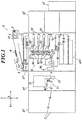
Fig. 1 is a schematic configuration diagram of an image forming system according to this embodiment. -
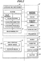
Fig. 2 is a functional block diagram of a main unit and an image reading apparatus. -
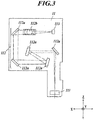
Fig. 3 is a side view of the internal configuration of an image reader. -
Fig. 4 is a schematic configuration diagram of the image reading apparatus. -
Fig. 5 is a schematic configuration diagram of a frame. -
Fig. 6 is a schematic configuration diagram of another frame. - Hereinafter, one or more embodiments of the present invention will be described with reference to the drawings. However, the scope of the invention is not limited to the disclosed embodiments.
- In the description below, the horizontal direction in
Fig. 1 corresponds to the X direction, the vertical direction corresponds to the Z direction, and a direction orthogonal to the X and Z directions or the front-back direction corresponds to the Y direction. - An image forming system G according to an embodiment will now be described.
- With reference to
Fig. 1 , the image forming system G includes a print controller g1, a sheet feeder g2, a main unit g3, an image reading apparatus g4, and a finishing apparatus g5. - The print controller g1 receives page description language (PDL) data from a computer terminal via a network and rasterizes the PDL data into bitmap image data.
- The print controller g1 generates image data for each of the colors cyan (C), magenta (M), yellow (Y), and black (K) and outputs the image data to the main unit g3.
- The sheet feeder g2 includes large-volume feeder trays.
- The sheet feeder g2 conveys sheets from a sheet feeder tray to the main unit g3 under an instruction from the main unit g3.
- An
image forming unit 8 of the main unit g3 forms an image on a sheet on the basis of image data of an original document D read by ascanner 6 or image data generated by the print controller g1. The main unit g3 conveys the sheet after the formation of the image to the image reading apparatus g4. - A
reader 11 of the reading apparatus g4 reads a reference image (providing a reference for, for example, color, tone correction, line width, color resist, and/or front/back alignment) on a sheet and outputs the read image data to ahardware processor 1. The image reading apparatus g4 conveys the sheet having the image read by thereader 11 to the finishing apparatus g5. - The finishing apparatus g5 carries out post-treatment on the sheet sent from the image reading apparatus g4 and ejects the post-treated sheet. Examples of the post-treatment includes, stapling, punching, folding, and bookbinding. The post-treatment is not essential and thus the finishing apparatus g5 carries out the post-treatment only after an instruction from the main unit g3. If the post-treatment is not instructed, the finishing apparatus g5 ejects the sheet without post-treatment.
- The configuration of the main unit g3 will now be described.
- With reference to
Figs. 1 and2 , the main unit g3 includes, ahardware processor 1, amemory 2, anoperation interface 3, adisplay 4, acommunicator 5, anautomatic sheet feeder 61, ascanner 6, animage processor 7, animage forming unit 8, astraightener 9, and sheet feeder trays g31. - The
hardware processor 1 includes a central processing unit (CPU) and a random access memory (RAM). Thehardware processor 1 reads programs stored in thememory 2 and controls the components of the image forming system G in accordance with these programs. - For example, the
hardware processor 1 feeds a sheet from the sheet feeder g2 or one of the sheet feeder tray g31 in response to an instruction of a job setting. Thehardware processor 1 allows theimage processor 7 to correct and process the image data and theimage forming unit 8 to form an image. In the case where the job setting includes the post-treatment, thehardware processor 1 instructs the finishing apparatus g5 to carry out the post-treatment. - The
memory 2 stores programs and files readable by thehardware processor 1. Thememory 2 may be a storage medium, such as a hard disk or a read only memory (ROM). Thememory 2 stores reference image data for adjustment of image quality. - The
operation interface 3 includes a touch panel integrated with operating keys and thedisplay 4 and outputs operating signals corresponding to operations of these components to thehardware processor 1. A user can operate theoperation interface 3 to input instructions on modification of the job settings and processing. - The
display 4 may be a liquid crystal display (LCD) and displays an operating menu and other images in accordance with instructions from thehardware processor 1. - The
communicator 5 establishes communication with another computer, such as a server or another image forming system, via a network under an instruction from thehardware processor 1. - The
automatic sheet feeder 61 includes a sheet tray for placing an original document D, a mechanism for conveying the original document D, and conveying rollers. Theautomatic sheet feeder 61 conveys the original document D to a predetermined conveying path. - The
scanner 6 includes an optical system including a light source and reflection mirrors. Thescanner 6 reads the image on the original document D conveyed along the predetermined conveying path or an original document D placed on a glass platen, generates an image data item for each of the colors red (R), green (G), and blue (B), and outputs the generated image data items to theimage processor 7. - The
image processor 7 corrects the image data from thescanner 6 or the print hardware processor g1, processes the corrected image data, and outputs the processed image data to theimage forming unit 8. - With reference to
Fig. 2 , theimage processor 7 includes acolor converter 71, atone corrector 72, and ahalftone processor 73. - The
color converter 71 conducts color conversion of the image data items of the colors R, G, and B from thescanner 6 and outputs image data of the colors C, M, Y, and K. - Alternatively, the
color converter 71 may conduct color conversion of the image data items of the colors C, M, Y, and K from the print hardware processor g1 for color correction, and output the color-corrected image data of the colors C, M, Y, and K. - During the color conversion, the
color converter 71 retrieves a lookup table (LUT) storing the color-converted tone values of the colors C, M, Y, and K in relation to the tones values of the colors R, G, and B. During the color correction, thecolor converter 71 retrieves an LUT storing the color-corrected tone values of the colors C, M, Y, and K in relation to the tone values of the colors C, M, Y, and K. - The
tone corrector 72 corrects the tone of the image data output from thecolor converter 71 or the print hardware processor g1. - During the tone correction, the
tone corrector 72 retrieves an LUT storing correction values in relation to tone values so as to match the tone properties of the image with target tone properties. Thetone corrector 72 retrieves correction values corresponding to the tone values of the pixels in the image data, from the LUT for tone correction, and outputs image data consisting of the correction values. - The
halftone processor 73 conducts halftone processing on the image data from thetone corrector 72. Examples of the halftone processing includes screen processing with a dither matrix and error diffusion. - The
halftone processor 73 outputs the image data after the halftone processing to theimage forming unit 8. - The
image forming unit 8 forms an image on a sheet on the basis of the image data from theimage processor 7. - With reference to
Fig. 1 , theimage forming unit 8 is provided with four sets of exposingunits 81,photoreceptors 82, and developingunits 83 for the respective colors C, M, Y, and K. Theimage forming unit 8 includes anintermediate transfer belt 84,secondary transfer rollers 85, and a fixingunit 86. - Each exposing
unit 81 includes laser diodes (LDs) or light emitting devices. The exposingunit 81 drives the LDs on the basis of the image data and illuminates the corresponding chargedphotoreceptor 82 with a laser beam for exposure. The relevant developingunit 83 feeds toner onto thephotoreceptor 82 with a charged developer roller and develops an electrostatic latent image in response to the exposure on thephotoreceptor 82. - The four images formed with the respective four color toners on the respective four
photoreceptors 82 are sequentially transferred to theintermediate transfer belt 84. This forms a color image on theintermediate transfer belt 84. Theintermediate transfer belt 84 is an endless belt wound around several rollers. Theintermediate transfer belt 84 rotates in response to the rotation of the rollers. - The
secondary transfer rollers 85 transfer the color image from theintermediate transfer belt 84 to the sheet fed from the sheet feeder g2 or the sheet feeder tray g31. The fixingunit 86 applies heat and pressure to the sheet to fix the color image to the sheet. - The
straightener 9 corrects deformation of the sheet due to the fixing to flatten the face of the sheet. The sheet readily deforms in the fixing process and should be flattened before reading of the reference image. Thus, thestraightener 9 is disposed between the fixingunit 86 and thereader 11 in the conveying direction of the sheet, as illustrated inFig. 1 . - The configuration of the image reading apparatus g4 will now be described.
- The image reading apparatus g4 includes a
reader 11, acorrector 12, asheet conveyer 13, and a cooler 14. - The
reader 11 reads the image formed on the sheet being conveyed along a conveying path R1 by thesheet conveyer 13, at a predetermined reading position. - With reference to
Figs. 1 and3 , thereader 11 includes alighting unit 111, anoptical system 112, and aCCD 113. Thelighting unit 111, theoptical system 112, and theCCD 113 are fixed to the interior of the housing of thereader 11. - The
lighting unit 111 includes a light source, such as an LED or a halogen lamp, and illuminates the sheet conveyed by conveyingrollers 131, at the reading position of thereader 11. - The
optical system 112 includesmirrors 112a (five according to this embodiment) and alens 112b. Theoptical system 112 focuses the light from thelighting unit 111 incident on the sheet (the image at the reading position), on theCCD 113. - The
CCD 113 reads the image formed on the sheet at the predetermined reading position. TheCCD 113 is a color line sensor that can read the entire length of the sheet in the width or Y direction. - The
reader 11, which has the configuration described above, can sequentially read the image formed on the sheet across the entire width as the sheet passes the reading position. For example, in this embodiment, thereader 11 reads a reference image (providing a reference for, for example, color, tone correction, line width, color resist, and/or front/back alignment) formed on a sheet, and feeds back the read image data to the image processor, the print controller, and sheet conveyer for correction. - The
corrector 12 is disposed below the conveying path R1 and faces thereader 11. Thecorrector 12 includes a white reference plate for determining the correction values for shading correction conducted during reading of the image. The white reference plate is disposed at the reading position and is read in intervals by theCCD 113 while no sheet is passing (for example, between consecutive sheets). - With reference to
Figs. 2 and4 , thesheet conveyer 13 includes conveyingrollers 131, a drivingmotor 132, and conveyingguides 133. - Several conveying
rollers 131 or conveyers are provided in the conveying path R1 so as to convey sheets along the conveying path R1. - The driving
motor 132 or conveyer driving unit drives the conveyingrollers 131 in accordance with instructions from thehardware processor 1. The drivingmotor 132 is disposed closer to the center of the sheet than the conveyingrollers 131 in the width or Y direction. - At least two conveying
guides 133 are provided in the conveying path R1 and guide the sheet conveyed by the conveyingrollers 131. - During reading of the image by the
reader 11, thesheet conveyer 13 conveys the sheet by the conveyingrollers 131 disposed along the conveying path R1 such that the sheet passes through the reading position of thereader 11 at a predetermined rate. Thesheet conveyer 13 conveys the sheet having the image read by thereader 11 to the finishing apparatus g5. - With reference to
Figs. 2 and4 , the cooler 14 includes ablast fan 141 that blows in a predetermined direction and a drivingmotor 142 that drives theblast fan 141. The drivingmotor 142 is disposed closer to the center of the sheet than theblast fan 141 in the width or Y direction. - The cooler 14 is fixed to a
conveyer housing 101 such that theblast fan 141 faces thelighting unit 111. In this way, the cooler 14 can blow thelighting unit 111 so as to cool thelighting unit 111. - With reference to
Fig. 4 , the conveying path R1, which is defined by the conveyingguides 133 and the bottom face of thereader 11, extends in a substantially linear line. The conveying path R1 guides the sheet having an image to the reading position and then guides the sheet in the ejecting direction after reading by thereader 11. - The
corrector 12, the sheet conveyer 13 (the conveyingrollers 131 and the driving motor 132), the cooler 14, and the conveying path R1 of the image reading apparatus g4 are fixed to theconveyer housing 101, except for thereader 11. - The
reader 11 and theconveyer housing 101 are separately fixed to aframe 102. - The configuration described above causes the vibration caused by collision of the sheet with the components such as the conveying
guides 133 and the conveyingrollers 131 to be transmitted to theconveyer housing 101, theframe 102, and thereader 11, in this order. This provides a sufficient length for the vibration to attenuate before it reaches thereader 11. - The
reader 11 and theconveyer housing 101 are movable relative to theframe 102. In detail, thereader 11 and theconveyer housing 101 can be pulled out from theframe 102. - The
reader 11 removable from theframe 102 allows ready replacement of thereader 11 in the case of failure of thereader 11. - The
conveyer housing 101 removable from theframe 102 allows ready removal of a sheet in the case of jamming of the sheet in the conveying path R1. - With reference to
Fig. 5 , theframe 102 includes columns 103 (four in this embodiment) and beams 104 connecting theadjacent columns 103. Thecolumns 103 and thebeams 104 are, for example, metal plates or pipes. Thecolumns 103 and thebeams 104 may be composed of any material that has a sufficient strength. Examples of such a material include steel and stainless steel. - The
frame 102 should not resonate with theconveyer housing 101 supporting the conveyingrollers 131, the drivingmotor 132, and the conveying path R1, which are vibration sources. Thus, the resonant frequency of theframe 102 should not be the operating frequency of theconveyer housing 101. Theframe 102 should have appropriate rigidity for supporting theconveyer housing 101 and thereader 11. Thus, theframe 102 should have high rigidity (i.e., high natural frequency). - In this embodiment, the
columns 103 serving as an external frame of the image reading apparatus g4 are connected by thebeams 104, to enhance the rigidity of theframe 102. - The
reader 11 is fixed to thebeams 104. This is because thereader 11 includesmirrors 112a having a low natural frequency of approximately 80 Hz and should be fixed to theframe 102 having a high natural frequency or high rigidity so that vibration does not propagate to the mirrors having a low natural frequency. - In this embodiment, the
reader 11 is fixed to thebeams 104 of theframe 102 to prevent propagation of vibration from theframe 102 to thereader 11. - The
columns 103 are provided with conveying-housing fixing members 105 that fix theconveyer housing 101 to theframe 102. Each of the conveying-housing fixing members 105 has a length smaller than the distance between theadjacent columns 103. Thus, the configuration according to this embodiment can prevent propagation of vibration from theconveyer housing 101 to theframe 102 because thecolumns 103 are not connected with the conveying-housing fixing members 105. - The conveying-
housing fixing members 105 are resilient components, such as springs. The conveying-housing fixing members 105 fix theconveyer housing 101 including vibration sources to theframe 102. The conveying-housing fixing members 105 are composed of a material having rigidity lower than that of thebeams 104. The spring constant of the conveying-housing fixing members 105 is adjusted such that the displacement caused by the weight of theconveyer housing 101 is no more than 1 mm. In this embodiment, the conveying-housing fixing members 105 are metal plates. - In this embodiment, the weight of the
conveyer housing 101 is increased by supporting the mechanism for conveying (including the conveyingrollers 131, the drivingmotor 132, and the conveying path R1). The increased weight reduces the natural frequency of theconveyer housing 101. - As described above, the
conveyer housing 101, which includes vibration sources, is supported by resilient components, and the weight of theconveyer housing 101 is increased to lower the natural frequency. This attenuates the vibration propagating from theconveyer housing 101, and thus isolates the vibration. - In general, the relative displacement of the
reader 11 and the sheet being conveyed in the image reading apparatus g4 should be within approximately 1 mm so as to achieve accurate reading of an image. For example, in the case where thereader 11 and theconveyer housing 101 are positioned with dampers composed of rubber having low strength, the relative displacement increases. Thus, thereader 11 and theconveyer housing 101 cannot be relatively positioned with high precision. - In this embodiment, the conveying-
housing fixing members 105 are metal plates having an appropriate strength. Thus, the relative displacement is small compared to that in a configuration of thereader 11 and theconveyer housing 101 positioned with dampers. - In this embodiment, the spring constant of the conveying-
housing fixing members 105 is adjusted such that the displacement caused by the weight of theconveyer housing 101 is no more than 1 mm. - In this way, the relative displacement of the
reader 11 and the sheet being conveyed does not exceed 1 mm. - As described above, the image reading apparatus g4 of the image forming system G according to this embodiment includes:
- a
reader 11 reading an image on a sheet at a predetermined reading position; - a conveying path R1 guiding the sheet having the image to the reading position and guiding the sheet in the ejecting direction after reading by the
reader 11; - a conveyer or conveying
rollers 131 conveying the sheet along the conveying path R1; - a conveyer driving unit or driving
motor 132 driving the conveyer; - a
conveyer housing 101 supporting the conveying path R1, the conveyer, and the conveyer driving unit; and - a
frame 102 includingcolumns 103 andbeams 104 that connect theadjacent columns 103 and individually fixing thereader 11 and theconveyer housing 101. - The
columns 103 are provided with resilient conveying-housing fixing members 105 having a length smaller than the distance between theadjacent columns 103. The conveying-housing fixing members 105 are composed of a material having rigidity lower than that of thebeams 104. Theconveyer housing 101 is fixed to theframe 102 with the conveying-housing fixing members 105, and thereader 11 is fixed to thebeams 104. - In the image reading apparatus g4 according to this embodiment, the
reader 11 is fixed to theframe 102 having high rigidity. This prevents the propagation of vibration from theframe 102 to thereader 11. - The
columns 103 are not connected with the conveying-housing fixing members 105. Thus, vibration can be prevented from propagating from theconveyer housing 101 to theframe 102. - The
conveyer housing 101 including vibration sources is supported by resilient components, and the weight of theconveyer housing 101 is increased to lower the natural frequency. This attenuates the vibration propagating from theconveyer housing 101, and thus isolates the vibration. - Thus, in the image reading apparatus g4 according to this embodiment, propagation of vibration to the
reader 11 can be prevented. This enables accurate reading of an image on a sheet. - The conveying-
housing fixing members 105 of the image reading apparatus g4 according to this embodiment are metal plates. - Thus, in the image reading apparatus g4 according to this embodiment, the relative displacement of the
reader 11 and the sheet being conveyed can be reduced. Thus, thereader 11 and theconveyer housing 101 can be relatively positioned with high precision. Moreover, the vibration propagating from theconveyer housing 101 can be attenuated. This can isolate the vibration. - The
reader 11 and theconveyer housing 101 of the image reading apparatus g4 according to this embodiment are movable relative to theframe 102. - Thus, in the image reading apparatus g4 according to this embodiment, the
reader 11 can be readily replaced in the case of failure of thereader 11. This reduces downtime and enhances productivity. In the case of jamming of a sheet in the conveying path R1, the jammed sheet can be readily removed. This reduces downtime and enhances productivity. - In the image reading apparatus g4 according to this embodiment, the spring constant of the conveying-
housing fixing members 105 is adjusted such that the displacement caused by the weight of theconveyer housing 101 is no more than 1 mm. - Thus, in the image reading apparatus g4 according to this embodiment, the relative displacement of the
reader 11 and the sheet being conveyed is not more than 1 mm. This achieves high accuracy in reading of an image. - The embodiments of the present invention have been described in detail. The embodiments should not be construed to limit the scope of the invention and may be modified within the scope of the invention.
- For example, in the embodiment described above, the
reader 11 faces thecorrector 12 across the conveying path R1, wherereader 11 is disposed above and thecorrector 12 is disposed below the conveying path R1. Alternatively, thereader 11 and thecorrector 12 may be disposed at any positions. For example, thecorrector 12 may face thereader 11 across the conveying path R1, where thecorrector 12 is disposed above and thereader 11 disposed below the conveying path R1. - In the case where the
corrector 12 faces thereader 11 across the conveying path R1, where thecorrector 12 is disposed above the conveying path R1 and thereader 11 is disposed below, the position of thebeams 104 fixing thereader 11 may be interchanged with the position of the conveying-housing fixing members 105 fixing theconveyer housing 101, as illustrated inFig. 6 . - In the embodiment described above, one
reader 11 and onecorrector 12 are provided. Alternatively, any number of thereader 11 and thecorrector 12 may be provided. For example, tworeaders 11 and twocorrectors 12 may be provided. In such a case, one of thereaders 11 faces one of thecorrectors 12 across the conveying path R1, where thereader 11 is disposed above the conveying path R1 and thecorrectors 12 is disposed below the conveying path R1, whereas theother reader 11 faces theother corrector 12 across the conveying path R1, where theother reader 11 is disposed below the conveying path R1 and theother corrector 12 is disposed above the conveying path R1. In this way, each pair of thereader 11 and thecorrector 12 can read each side of a sheet, so that both sides of a sheet are read in a single operation. - In the embodiment described above, the conveying-
housing fixing members 105 are metal plates. Alternatively, the conveying-housing fixing members 105 may be composed of any other material. In detail, the conveying-housing fixing members 105 may be composed of any material having resilience and strength sufficient for relatively positioning thereader 11 and the sheet being conveyed with high precision. An example of such a material includes reinforced resin. - In the embodiment described above, the
adjacent columns 103 are connected with thebeams 104 at all four sides. Alternatively, thebeams 104 may connect thecolumns 103 at less than four sides. Although connecting thecolumns 103 with thebeams 104 at all four sides is preferred in consideration of high rigidity of theframe 102, thebeams 104 may connect thecolumns 103 in at least the directions parallel to the conveying direction. - In the embodiment described above, the conveying path R1 has a substantially linear shape. Alternatively, the conveying path R1 may have any other shape. In specific, the conveying path R1 may include a curved portion.
- In the embodiment described above, the housing of the
reader 11 has an L shape, that is, a bottom face downward protrusion (on the right in the drawing). Alternatively, the housing of thereader 11 may have any other shape. In specific, the housing of thereader 11 may have any shape that can provide a light path long enough for reading. For example, the housing of thereader 11 may have a shape of a box with no downward protrusion. Alternatively, the housing of thereader 11 may have a downward protrusion in the central region of the bottom face. In such a case, it is preferred that the contact area of the bottom face of thereader 11, which also defines the conveying path R1, and the sheet be small (for example, the bottom face have a protrusion at the edge or in the central area) so as to prevent vibration caused by contact of the bottom face of thereader 11 and the sheet. - The detailed configuration and operation of the components of the image forming system described above may be appropriately modified without departing from the scope of the present invention.
- Although embodiments of the present invention have been described and illustrated in detail, the disclosed embodiments are made for purposes of illustration and example only and not limitation. The scope of the present invention should be interpreted by terms of the appended claims.
Claims (10)
- An image reading apparatus, comprising:a reader which reads an image on a sheet at a predetermined reading position;a conveying path which guides the sheet having the image to the reading position and which guides the sheet read by the reader in an ejecting direction;a conveyer which conveys the sheet along the conveying path;a conveyer driving unit which drives the conveyer;a conveyer housing which supports the conveying path, the conveyer, and the conveyer driving unit; anda frame which comprises columns and beams that connect the adjacent columns, the frame individually fixing the reader and the conveyer housing, wherein,the columns are provided with resilient conveying-housing fixing members, the conveying-housing fixing members each having a length smaller than the distance between the adjacent columns,the conveying-housing fixing members comprise a material having rigidity lower than the material of the beams,the conveyer housing is fixed to the frame by the conveying-housing fixing members, andthe reader is fixed to the beams.
- The image reading apparatus according to claim 1, wherein the conveying-housing fixing members comprise metal plates.
- The image reading apparatus according to claim 1, wherein the reader and the conveyer housing are movable relative to the frame.
- The image reading apparatus according to claim 1, wherein the spring constant of the conveying-housing fixing members is adjusted to achieve a displacement of 1 mm or less caused by the weight of the conveyer housing.
- The image reading apparatus according to claim 1, wherein a portion of the reader defines the conveying path.
- The image reading apparatus according to claim 1, wherein the columns and the beams comprise metal plates.
- The image reading apparatus according to claim 1, wherein,
the columns comprise four columns, and the beams comprise four beams, and each of the four beams connect the adjacent columns of the frame. - The image reading apparatus according to claim 1, wherein the conveying path comprises a curved portion.
- The image reading apparatus according to claim 1, wherein the housing of the reader partially protrudes toward the sheet.
- An image forming system comprising:an image forming unit which forms an image based on image data; andthe image reading apparatus according to claim 1 which reads the image formed by the image forming unit on a sheet.
Applications Claiming Priority (1)
| Application Number | Priority Date | Filing Date | Title |
|---|---|---|---|
| JP2017062810A JP6540739B2 (en) | 2017-03-28 | 2017-03-28 | Image reading apparatus and image forming apparatus |
Publications (1)
| Publication Number | Publication Date |
|---|---|
| EP3382456A1 true EP3382456A1 (en) | 2018-10-03 |
Family
ID=61569128
Family Applications (1)
| Application Number | Title | Priority Date | Filing Date |
|---|---|---|---|
| EP18160046.1A Withdrawn EP3382456A1 (en) | 2017-03-28 | 2018-03-05 | Image reading apparatus and image forming system |
Country Status (4)
| Country | Link |
|---|---|
| US (1) | US10491766B2 (en) |
| EP (1) | EP3382456A1 (en) |
| JP (1) | JP6540739B2 (en) |
| CN (1) | CN108668046B (en) |
Families Citing this family (2)
| Publication number | Priority date | Publication date | Assignee | Title |
|---|---|---|---|---|
| JP2023145279A (en) | 2022-03-28 | 2023-10-11 | 富士フイルムビジネスイノベーション株式会社 | Recording material transport device and image forming system |
| JP2023145281A (en) | 2022-03-28 | 2023-10-11 | 富士フイルムビジネスイノベーション株式会社 | Recording material transport device and image forming system |
Citations (5)
| Publication number | Priority date | Publication date | Assignee | Title |
|---|---|---|---|---|
| US5539447A (en) * | 1992-09-28 | 1996-07-23 | Fujitsu Limited | Optical scanning unit and image forming apparatus using the same with rotating lever attached to a cover for light emission and prevention |
| US20010019402A1 (en) * | 1997-07-28 | 2001-09-06 | Fuji Photo Film Co., Ltd. | Image recording apparatus |
| US20050094218A1 (en) * | 2003-10-15 | 2005-05-05 | Kabushiki Kaisha Toshiba | Image reading apparatus |
| JP2008139394A (en) * | 2006-11-30 | 2008-06-19 | Konica Minolta Business Technologies Inc | Image forming apparatus |
| JP2016001814A (en) * | 2014-06-12 | 2016-01-07 | コニカミノルタ株式会社 | Image reading device and image forming apparatus |
Family Cites Families (19)
| Publication number | Priority date | Publication date | Assignee | Title |
|---|---|---|---|---|
| JPS61230463A (en) * | 1985-04-03 | 1986-10-14 | Fuji Photo Film Co Ltd | Image reader |
| US4686581A (en) * | 1985-08-09 | 1987-08-11 | Ana Tech Corporation | Document scanning system |
| DE3605463C1 (en) * | 1986-02-20 | 1987-04-23 | Agfa Gevaert Ag | Copier |
| US4792858A (en) * | 1987-06-05 | 1988-12-20 | Powers Chemco, Inc. | Optical scanning system having a rotatable platen assembly and method for loading same |
| US5442466A (en) * | 1992-07-13 | 1995-08-15 | Mita Industrial Co., Ltd. | Plate sheet conveying mechanism having integrally formed sheet guide |
| US5912746A (en) * | 1996-03-14 | 1999-06-15 | Intergraph Corporation | Contact image sensor for large format scanner |
| JP3462067B2 (en) * | 1998-02-03 | 2003-11-05 | シャープ株式会社 | Image forming device |
| DE19944494A1 (en) * | 1998-09-18 | 2000-03-23 | Fuji Photo Film Co Ltd | Image information medium holder has image reader mounted on main housing via vibration protection arrangement and carrier holder part at reading position on which carrier can be mounted |
| JP3548494B2 (en) * | 2000-04-18 | 2004-07-28 | キヤノン株式会社 | Image forming device |
| JP2002328434A (en) * | 2001-04-26 | 2002-11-15 | Konica Corp | Image recorder |
| JP2003107593A (en) * | 2001-09-28 | 2003-04-09 | Fuji Photo Optical Co Ltd | Carriage support structure of image processor |
| JP4429856B2 (en) * | 2004-09-29 | 2010-03-10 | ブラザー工業株式会社 | Recording medium conveying apparatus and image forming apparatus |
| JP2006240757A (en) * | 2005-02-28 | 2006-09-14 | Sharp Corp | Image forming apparatus |
| US7329893B2 (en) * | 2005-12-28 | 2008-02-12 | Carestream Health, Inc. | Storage phosphor reader having frame vibration isolation |
| JP4862634B2 (en) * | 2006-11-30 | 2012-01-25 | コニカミノルタビジネステクノロジーズ株式会社 | Image forming apparatus |
| JP5454288B2 (en) * | 2010-03-26 | 2014-03-26 | 富士ゼロックス株式会社 | Image forming apparatus |
| JP5413618B2 (en) * | 2011-06-16 | 2014-02-12 | コニカミノルタ株式会社 | Image forming apparatus |
| JP6201625B2 (en) * | 2013-10-22 | 2017-09-27 | 富士ゼロックス株式会社 | Paper transport device, document reading device, and image forming device |
| JP6446831B2 (en) * | 2014-05-16 | 2019-01-09 | ブラザー工業株式会社 | Image forming apparatus |
-
2017
- 2017-03-28 JP JP2017062810A patent/JP6540739B2/en active Active
-
2018
- 2018-03-05 EP EP18160046.1A patent/EP3382456A1/en not_active Withdrawn
- 2018-03-14 US US15/920,523 patent/US10491766B2/en active Active
- 2018-03-27 CN CN201810257729.5A patent/CN108668046B/en active Active
Patent Citations (6)
| Publication number | Priority date | Publication date | Assignee | Title |
|---|---|---|---|---|
| US5539447A (en) * | 1992-09-28 | 1996-07-23 | Fujitsu Limited | Optical scanning unit and image forming apparatus using the same with rotating lever attached to a cover for light emission and prevention |
| US20010019402A1 (en) * | 1997-07-28 | 2001-09-06 | Fuji Photo Film Co., Ltd. | Image recording apparatus |
| US20050094218A1 (en) * | 2003-10-15 | 2005-05-05 | Kabushiki Kaisha Toshiba | Image reading apparatus |
| JP2005123777A (en) | 2003-10-15 | 2005-05-12 | Toshiba Corp | Height-adjustable image reader |
| JP2008139394A (en) * | 2006-11-30 | 2008-06-19 | Konica Minolta Business Technologies Inc | Image forming apparatus |
| JP2016001814A (en) * | 2014-06-12 | 2016-01-07 | コニカミノルタ株式会社 | Image reading device and image forming apparatus |
Also Published As
| Publication number | Publication date |
|---|---|
| US20180288252A1 (en) | 2018-10-04 |
| CN108668046B (en) | 2020-01-17 |
| JP2018166267A (en) | 2018-10-25 |
| JP6540739B2 (en) | 2019-07-10 |
| US10491766B2 (en) | 2019-11-26 |
| CN108668046A (en) | 2018-10-16 |
Similar Documents
| Publication | Publication Date | Title |
|---|---|---|
| JP6323191B2 (en) | Image reading apparatus and image forming apparatus | |
| US9307097B2 (en) | Image forming apparatus | |
| US20170153586A1 (en) | Image forming apparatus | |
| US10491766B2 (en) | Image reading apparatus and image forming system | |
| JP2016118674A (en) | Image forming apparatus | |
| CN108696656B (en) | Reading device and image forming apparatus | |
| JP2014010422A (en) | Image forming device and program | |
| US10506126B2 (en) | Image reading apparatus and image forming system | |
| JP6544334B2 (en) | Image reading apparatus and image forming apparatus | |
| AU2011202939A1 (en) | Detecting device, detecting method, and image forming apparatus | |
| US11422496B2 (en) | Image forming apparatus | |
| JP2020012883A (en) | Image forming apparatus | |
| JP7215213B2 (en) | inspection equipment | |
| JP7167199B2 (en) | Image reading device and image forming device | |
| US20250142009A1 (en) | Image formation apparatus | |
| US20200296225A1 (en) | Image forming apparatus that uses spectral sensor | |
| US20120182368A1 (en) | Optical scanning device and image forming apparatus | |
| JP2017085299A (en) | Image reading device and image forming apparatus | |
| JP2018142845A (en) | Image reading device and image forming apparatus | |
| JP6860036B2 (en) | Image reader and image forming device | |
| CN206060918U (en) | Scanning means and image processing system | |
| JP6248793B2 (en) | Image reading apparatus and image forming apparatus | |
| JP4499057B2 (en) | Document reader and copier | |
| JP6895109B2 (en) | Image reader and image forming device | |
| JP2025012906A (en) | Image forming system |
Legal Events
| Date | Code | Title | Description |
|---|---|---|---|
| PUAI | Public reference made under article 153(3) epc to a published international application that has entered the european phase |
Free format text: ORIGINAL CODE: 0009012 |
|
| STAA | Information on the status of an ep patent application or granted ep patent |
Free format text: STATUS: THE APPLICATION HAS BEEN PUBLISHED |
|
| AK | Designated contracting states |
Kind code of ref document: A1 Designated state(s): AL AT BE BG CH CY CZ DE DK EE ES FI FR GB GR HR HU IE IS IT LI LT LU LV MC MK MT NL NO PL PT RO RS SE SI SK SM TR |
|
| AX | Request for extension of the european patent |
Extension state: BA ME |
|
| STAA | Information on the status of an ep patent application or granted ep patent |
Free format text: STATUS: REQUEST FOR EXAMINATION WAS MADE |
|
| 17P | Request for examination filed |
Effective date: 20190325 |
|
| RBV | Designated contracting states (corrected) |
Designated state(s): AL AT BE BG CH CY CZ DE DK EE ES FI FR GB GR HR HU IE IS IT LI LT LU LV MC MK MT NL NO PL PT RO RS SE SI SK SM TR |
|
| STAA | Information on the status of an ep patent application or granted ep patent |
Free format text: STATUS: EXAMINATION IS IN PROGRESS |
|
| 17Q | First examination report despatched |
Effective date: 20190814 |
|
| STAA | Information on the status of an ep patent application or granted ep patent |
Free format text: STATUS: THE APPLICATION IS DEEMED TO BE WITHDRAWN |
|
| 18D | Application deemed to be withdrawn |
Effective date: 20200225 |