EP3382438A1 - Endoscope objective optical system - Google Patents
Endoscope objective optical system Download PDFInfo
- Publication number
- EP3382438A1 EP3382438A1 EP16868291.2A EP16868291A EP3382438A1 EP 3382438 A1 EP3382438 A1 EP 3382438A1 EP 16868291 A EP16868291 A EP 16868291A EP 3382438 A1 EP3382438 A1 EP 3382438A1
- Authority
- EP
- European Patent Office
- Prior art keywords
- optical system
- denotes
- objective optical
- endoscope objective
- lens
- Prior art date
- Legal status (The legal status is an assumption and is not a legal conclusion. Google has not performed a legal analysis and makes no representation as to the accuracy of the status listed.)
- Withdrawn
Links
- 230000003287 optical effect Effects 0.000 title claims abstract description 140
- 230000014509 gene expression Effects 0.000 claims abstract description 35
- 239000007787 solid Substances 0.000 claims abstract description 4
- 238000010521 absorption reaction Methods 0.000 claims description 15
- 230000004075 alteration Effects 0.000 description 52
- 201000009310 astigmatism Diseases 0.000 description 41
- 238000010586 diagram Methods 0.000 description 16
- 239000012790 adhesive layer Substances 0.000 description 10
- 230000001954 sterilising effect Effects 0.000 description 9
- 238000004659 sterilization and disinfection Methods 0.000 description 9
- 238000004513 sizing Methods 0.000 description 8
- BIIBYWQGRFWQKM-JVVROLKMSA-N (2S)-N-[4-(cyclopropylamino)-3,4-dioxo-1-[(3S)-2-oxopyrrolidin-3-yl]butan-2-yl]-2-[[(E)-3-(2,4-dichlorophenyl)prop-2-enoyl]amino]-4,4-dimethylpentanamide Chemical compound CC(C)(C)C[C@@H](C(NC(C[C@H](CCN1)C1=O)C(C(NC1CC1)=O)=O)=O)NC(/C=C/C(C=CC(Cl)=C1)=C1Cl)=O BIIBYWQGRFWQKM-JVVROLKMSA-N 0.000 description 6
- 238000009826 distribution Methods 0.000 description 4
- 230000002349 favourable effect Effects 0.000 description 4
- 206010007027 Calculus urinary Diseases 0.000 description 3
- 208000009911 Urinary Calculi Diseases 0.000 description 3
- 238000000034 method Methods 0.000 description 3
- 230000035882 stress Effects 0.000 description 3
- 229910019655 synthetic inorganic crystalline material Inorganic materials 0.000 description 3
- 230000000694 effects Effects 0.000 description 2
- 239000011521 glass Substances 0.000 description 2
- 239000000463 material Substances 0.000 description 2
- 230000002093 peripheral effect Effects 0.000 description 2
- 238000004904 shortening Methods 0.000 description 2
- QIVUCLWGARAQIO-OLIXTKCUSA-N (3s)-n-[(3s,5s,6r)-6-methyl-2-oxo-1-(2,2,2-trifluoroethyl)-5-(2,3,6-trifluorophenyl)piperidin-3-yl]-2-oxospiro[1h-pyrrolo[2,3-b]pyridine-3,6'-5,7-dihydrocyclopenta[b]pyridine]-3'-carboxamide Chemical compound C1([C@H]2[C@H](N(C(=O)[C@@H](NC(=O)C=3C=C4C[C@]5(CC4=NC=3)C3=CC=CN=C3NC5=O)C2)CC(F)(F)F)C)=C(F)C=CC(F)=C1F QIVUCLWGARAQIO-OLIXTKCUSA-N 0.000 description 1
- HFGHRUCCKVYFKL-UHFFFAOYSA-N 4-ethoxy-2-piperazin-1-yl-7-pyridin-4-yl-5h-pyrimido[5,4-b]indole Chemical compound C1=C2NC=3C(OCC)=NC(N4CCNCC4)=NC=3C2=CC=C1C1=CC=NC=C1 HFGHRUCCKVYFKL-UHFFFAOYSA-N 0.000 description 1
- 241000894006 Bacteria Species 0.000 description 1
- 206010010071 Coma Diseases 0.000 description 1
- 239000011248 coating agent Substances 0.000 description 1
- 238000000576 coating method Methods 0.000 description 1
- 239000006059 cover glass Substances 0.000 description 1
- 238000005520 cutting process Methods 0.000 description 1
- 238000003745 diagnosis Methods 0.000 description 1
- 230000003670 easy-to-clean Effects 0.000 description 1
- 238000004519 manufacturing process Methods 0.000 description 1
- AYOOGWWGECJQPI-NSHDSACASA-N n-[(1s)-1-(5-fluoropyrimidin-2-yl)ethyl]-3-(3-propan-2-yloxy-1h-pyrazol-5-yl)imidazo[4,5-b]pyridin-5-amine Chemical compound N1C(OC(C)C)=CC(N2C3=NC(N[C@@H](C)C=4N=CC(F)=CN=4)=CC=C3N=C2)=N1 AYOOGWWGECJQPI-NSHDSACASA-N 0.000 description 1
- VOVZXURTCKPRDQ-CQSZACIVSA-N n-[4-[chloro(difluoro)methoxy]phenyl]-6-[(3r)-3-hydroxypyrrolidin-1-yl]-5-(1h-pyrazol-5-yl)pyridine-3-carboxamide Chemical compound C1[C@H](O)CCN1C1=NC=C(C(=O)NC=2C=CC(OC(F)(F)Cl)=CC=2)C=C1C1=CC=NN1 VOVZXURTCKPRDQ-CQSZACIVSA-N 0.000 description 1
- -1 neodymium yttrium aluminum Chemical compound 0.000 description 1
- XULSCZPZVQIMFM-IPZQJPLYSA-N odevixibat Chemical compound C12=CC(SC)=C(OCC(=O)N[C@@H](C(=O)N[C@@H](CC)C(O)=O)C=3C=CC(O)=CC=3)C=C2S(=O)(=O)NC(CCCC)(CCCC)CN1C1=CC=CC=C1 XULSCZPZVQIMFM-IPZQJPLYSA-N 0.000 description 1
- 230000008646 thermal stress Effects 0.000 description 1
- 238000002834 transmittance Methods 0.000 description 1
- KMIOJWCYOHBUJS-HAKPAVFJSA-N vorolanib Chemical compound C1N(C(=O)N(C)C)CC[C@@H]1NC(=O)C1=C(C)NC(\C=C/2C3=CC(F)=CC=C3NC\2=O)=C1C KMIOJWCYOHBUJS-HAKPAVFJSA-N 0.000 description 1
- XLYOFNOQVPJJNP-UHFFFAOYSA-N water Chemical compound O XLYOFNOQVPJJNP-UHFFFAOYSA-N 0.000 description 1
- 229910019901 yttrium aluminum garnet Inorganic materials 0.000 description 1
Images






Classifications
-
- G—PHYSICS
- G02—OPTICS
- G02B—OPTICAL ELEMENTS, SYSTEMS OR APPARATUS
- G02B23/00—Telescopes, e.g. binoculars; Periscopes; Instruments for viewing the inside of hollow bodies; Viewfinders; Optical aiming or sighting devices
- G02B23/24—Instruments or systems for viewing the inside of hollow bodies, e.g. fibrescopes
- G02B23/2476—Non-optical details, e.g. housings, mountings, supports
- G02B23/2492—Arrangements for use in a hostile environment, e.g. a very hot, cold or radioactive environment
-
- A—HUMAN NECESSITIES
- A61—MEDICAL OR VETERINARY SCIENCE; HYGIENE
- A61B—DIAGNOSIS; SURGERY; IDENTIFICATION
- A61B1/00—Instruments for performing medical examinations of the interior of cavities or tubes of the body by visual or photographical inspection, e.g. endoscopes; Illuminating arrangements therefor
- A61B1/00064—Constructional details of the endoscope body
- A61B1/00071—Insertion part of the endoscope body
- A61B1/0008—Insertion part of the endoscope body characterised by distal tip features
- A61B1/00096—Optical elements
-
- A—HUMAN NECESSITIES
- A61—MEDICAL OR VETERINARY SCIENCE; HYGIENE
- A61B—DIAGNOSIS; SURGERY; IDENTIFICATION
- A61B1/00—Instruments for performing medical examinations of the interior of cavities or tubes of the body by visual or photographical inspection, e.g. endoscopes; Illuminating arrangements therefor
- A61B1/00163—Optical arrangements
- A61B1/00186—Optical arrangements with imaging filters
-
- A—HUMAN NECESSITIES
- A61—MEDICAL OR VETERINARY SCIENCE; HYGIENE
- A61B—DIAGNOSIS; SURGERY; IDENTIFICATION
- A61B1/00—Instruments for performing medical examinations of the interior of cavities or tubes of the body by visual or photographical inspection, e.g. endoscopes; Illuminating arrangements therefor
- A61B1/00163—Optical arrangements
- A61B1/00188—Optical arrangements with focusing or zooming features
-
- A—HUMAN NECESSITIES
- A61—MEDICAL OR VETERINARY SCIENCE; HYGIENE
- A61B—DIAGNOSIS; SURGERY; IDENTIFICATION
- A61B1/00—Instruments for performing medical examinations of the interior of cavities or tubes of the body by visual or photographical inspection, e.g. endoscopes; Illuminating arrangements therefor
- A61B1/04—Instruments for performing medical examinations of the interior of cavities or tubes of the body by visual or photographical inspection, e.g. endoscopes; Illuminating arrangements therefor combined with photographic or television appliances
- A61B1/05—Instruments for performing medical examinations of the interior of cavities or tubes of the body by visual or photographical inspection, e.g. endoscopes; Illuminating arrangements therefor combined with photographic or television appliances characterised by the image sensor, e.g. camera, being in the distal end portion
-
- A—HUMAN NECESSITIES
- A61—MEDICAL OR VETERINARY SCIENCE; HYGIENE
- A61B—DIAGNOSIS; SURGERY; IDENTIFICATION
- A61B1/00—Instruments for performing medical examinations of the interior of cavities or tubes of the body by visual or photographical inspection, e.g. endoscopes; Illuminating arrangements therefor
- A61B1/04—Instruments for performing medical examinations of the interior of cavities or tubes of the body by visual or photographical inspection, e.g. endoscopes; Illuminating arrangements therefor combined with photographic or television appliances
- A61B1/05—Instruments for performing medical examinations of the interior of cavities or tubes of the body by visual or photographical inspection, e.g. endoscopes; Illuminating arrangements therefor combined with photographic or television appliances characterised by the image sensor, e.g. camera, being in the distal end portion
- A61B1/051—Details of CCD assembly
-
- G—PHYSICS
- G02—OPTICS
- G02B—OPTICAL ELEMENTS, SYSTEMS OR APPARATUS
- G02B23/00—Telescopes, e.g. binoculars; Periscopes; Instruments for viewing the inside of hollow bodies; Viewfinders; Optical aiming or sighting devices
- G02B23/24—Instruments or systems for viewing the inside of hollow bodies, e.g. fibrescopes
- G02B23/2407—Optical details
- G02B23/2423—Optical details of the distal end
- G02B23/243—Objectives for endoscopes
-
- G—PHYSICS
- G02—OPTICS
- G02B—OPTICAL ELEMENTS, SYSTEMS OR APPARATUS
- G02B5/00—Optical elements other than lenses
- G02B5/20—Filters
- G02B5/208—Filters for use with infrared or ultraviolet radiation, e.g. for separating visible light from infrared and/or ultraviolet radiation
-
- G—PHYSICS
- G02—OPTICS
- G02B—OPTICAL ELEMENTS, SYSTEMS OR APPARATUS
- G02B9/00—Optical objectives characterised both by the number of the components and their arrangements according to their sign, i.e. + or -
- G02B9/04—Optical objectives characterised both by the number of the components and their arrangements according to their sign, i.e. + or - having two components only
- G02B9/10—Optical objectives characterised both by the number of the components and their arrangements according to their sign, i.e. + or - having two components only one + and one - component
-
- G—PHYSICS
- G02—OPTICS
- G02B—OPTICAL ELEMENTS, SYSTEMS OR APPARATUS
- G02B13/00—Optical objectives specially designed for the purposes specified below
- G02B13/04—Reversed telephoto objectives
-
- G—PHYSICS
- G02—OPTICS
- G02B—OPTICAL ELEMENTS, SYSTEMS OR APPARATUS
- G02B7/00—Mountings, adjusting means, or light-tight connections, for optical elements
- G02B7/02—Mountings, adjusting means, or light-tight connections, for optical elements for lenses
- G02B7/028—Mountings, adjusting means, or light-tight connections, for optical elements for lenses with means for compensating for changes in temperature or for controlling the temperature; thermal stabilisation
Definitions
- the present invention relates to an endoscope objective optical system, and particularly to an electronic endoscope for a medical application, and more particularly to an endoscope objective optical system that is suitable for autoclave sterilization and a treatment using laser light.
- an endoscope is to be used for a treatment by laser light, such as a urinary-calculus treatment.
- laser light such as Nd-YAG laser (neodymium yttrium aluminum garnet, wavelength 1064 nm) to be irradiated to the urinary calculus is incident on an image pickup element, halation of an endoscope image occurs.
- Nd-YAG laser neodymium yttrium aluminum garnet, wavelength 1064 nm
- laser light of a wavelength of a visible-light region such as a wavelength close to an infra-red region
- halation of an endoscope image occurs.
- a cut filter having an adequate optical density to an optical system.
- a filter that cuts laser light of a predetermined wavelength region, which is a cause of halation, is to be inserted into an optical path.
- cut filters are broadly divided into reflection-type cut filters and absorption-type cut filters.
- the reflection-type cut filter reflects light of a predetermined wavelength, and does not let to pass through. In a case of using the reflection-type cut filter, light reflected becomes a cause of halation which is optically undesirable.
- the absorption-type cut filter absorbs light of a predetermined band by a filter. Therefore, the absorption-type cut filter does not give rise to reflected light that is unnecessary. Consequently, for preventing halation, it is desirable to dispose an absorption-type cut filter having an adequate optical density in an optical path of the optical system.
- an endoscope objective optical system has a mechanical durability at the time of autoclave, and includes an absorption-type cut filter having an adequate thickness for preventing halation due to laser light, thereby realizing a compact arrangement with favorable productivity.
- Patent literatures 1, 2, and 3 are examples of an arrangement of an endoscope objective optical system in which an optical element is small-sized, and a filter that cuts predetermined wavelength regions is disposed.
- Patent Literature 1 An objective lens for a small-size endoscope has been disclosed in Patent Literature 1.
- Patent Literature 1 is regarding a technology related to a small-size optical system with favorable productivity. The technology regulates a power distribution for each lens group, and an outer diameter and a curvature of an element.
- Patent Literature 1 shortening of an overall length which is significant for small-sizing of an inserting portion of the endoscope has not been taken into consideration. Moreover, in a reusable endoscope objective optical system, cleansing and sterilization of the endoscope is necessary. For this, it is preferable that an object-side surface of a first lens nearest to object be a flat surface which is easy to clean. In an arrangement in Patent Literature 1, when an object-side surface of a first lens is let to be a flat surface, a cover glass is necessary. Consequently, the overall length becomes long.
- Patent Literature 2 A small-size optical system including two groups having a positive refractive power, which enables inserting of an infra-red absorption filter while maintaining a favorable workability has been disclosed in Patent Literature 2.
- the infra-red absorption-type filter has an adequate optical density.
- a thickness of the infra-red absorption-type filter becomes large. Consequently, in a case of realizing small-sizing of the overall optical system while maintaining an adequate thickness of the infra-red absorption-type filter, the thickness of the infra-red absorption-type filter occupying the overall length of lenses becomes large as the small-sizing progresses.
- Patent Literature 2 in a case of inserting the infra-red absorption-type filter having an adequate thickness into an optical path, light ray height becomes high thereby making an outer diameter of the optical system large. Therefore, Patent Literature 2 is not adequate as a technology for realizing small-sizing of the optical system.
- Patent Literature 3 A small-size endoscope objective optical system that is easy to process and assemble has been disclosed in Patent Literature 3.
- a thickness of each optical component being thin the workability is degraded.
- a dimensional tolerance of an inner diameter of a frame and an outer diameter of a lens compared to a size of an optical element becomes large. Therefore, when thin optical components are used, tilting and decentering occur substantially, and sometimes an adjustment becomes necessary. For such reason, in a small-size optical system, it is preferable that the optical elements be not thin. From this point, an arrangement according to Patent Literature 3 is not adequate for realizing a small-size optical system with a favorable assemblability.
- the present invention has been made in view of the abovementioned problems, and an object of the present invention is to provide an endoscope objective optical system resistant to a temperature change at the time of autoclave, which prevents halation due to laser light, and in which an overall length of the optical system is short and the processing and assembling of lenses is easy.
- the present invention is an endoscope objective optical system that is to be combined with a solid image pickup element, comprising in order from an object side, a planoconcave negative lens, an absorption-type filter, an aperture stop, and a planoconvex positive lens, wherein the following conditional expression (1) is satisfied: 0.5 ⁇ tg 1 / tl ⁇ 0.8 where,
- the present inventions shows an effect that it is possible to provide an endoscope objective optical system resistant to a temperature change at the time of autoclave, which prevents the halation due to laser light, and in which an overall length of the optical system is short and the processing and assembling of lenses is easy.
- Fig. 1 is a cross-sectional view of a lens arrangement of an endoscope objective optical system according to an embodiment.
- the present embodiment is an endoscope objective optical system that is to be combined with a solid image pickup element, which includes in order from an object side, a planoconcave negative lens L1 having a flat surface directed toward the object side, a flare aperture FS, an absorption-type filter (plane parallel plate) F1, an aperture stop S, and a planoconvex positive lens L2 having a flat surface directed toward the object side, wherein the following conditional expression (1) is satisfied: 0.5 ⁇ tg 1 / tl ⁇ 0.8 where,
- Parameter tg1 corresponds to a length of a portion including almost all lenses having a power.
- Conditional expression (1) regulates a proportion of parameter tg1 occupying the overall length.
- conditional expression (1) By letting so as not to fall below a lower limit value of conditional expression (1), a back focus of the endoscope objective optical system becomes short, and shortening of the overall length is facilitated. Moreover, a thickness of each optical element becomes large, and processing, holding, and assembling of components become easy.
- a thickness of the optical element contributes also to an improvement in durability of the optical element with respect to a thermal stress exerted from a holding frame at the time of autoclave.
- the thickness of the optical element such as the absorption-type filter (plane parallel plate) F1 enables to cut laser light of a predetermined wavelength region by adequate absorption. Accordingly, it is possible to prevent halation of an endoscope image due to laser light for target for example.
- an endoscope when an endoscope is to be used for a treatment by laser light, such as the urinary-calculus treatment, laser light for crushing such as Nd-YAG is irradiated to a calculus.
- laser light for crushing such as Nd-YAG is irradiated to a calculus.
- conditional expression (1) In a case of exceeding an upper limit value of conditional expression (1), it is not possible to secure a back-focus length required for focus adjustment.
- conditional expression (1') be satisfied instead of conditional expression (1) .
- the absorption-type filter is an infra-red absorption filter.
- laser light of an infra-red region which is visible light is to be used as the laser light for target. Accordingly, by cutting the laser light of the infra-red region, it is possible to reduce the halation of the endoscope image.
- the 'total thickness' refers to a thickness of an outer peripheral portion of the optical element.
- the 'thickness' refers to a thickness on an optical axis of the optical element.
- Conditional expressions (2), (3), and (4) regulate a relationship of the outer diameter and the thickness of the planoconcave negative lens L1, the absorption-type filter (plane parallel plate) F1, and the planoconvex positive lens L2 respectively.
- conditional expressions (2), (3), and (4) In a case of falling below lower limit values of conditional expressions (2), (3), and (4), processing and assemblability of the optical system is deteriorated, and resistance with respect to the autoclave is also degraded.
- planoconcave negative lens L1 the absorption-type filter (plane parallel plate) F1
- planoconvex positive lens L2 have tilting and decentering, and an astigmatism and a coma occur.
- conditional expressions (2), (3), and (4) In a case of exceeding upper limit values of conditional expressions (2), (3), and (4), it results in the overall length of the optical system becoming long.
- Fig. 12 is a diagram showing tilt of an optical element L in the form of a plane parallel plate having an outer diameter ⁇ .
- a value of (a total thickness of the optical element L) / (the outer diameter ⁇ of the optical element L) is required to be higher than 0.32.
- conditional expressions (2'), (3'), and (4') be satisfied instead of conditional expressions (2), (3), and (4): 0.33 ⁇ tn / ⁇ n ⁇ 1.34 0.33 ⁇ tIRCF / ⁇ IRCF ⁇ 1.34 and 0.33 ⁇ tp / ⁇ p ⁇ 1.34
- Conditional expression (2-1) regulates a power distribution of the biconcave negative lens L1 and the overall endoscope objective optical system.
- conditional expression (2-1) In a case of exceeding an upper limit value of conditional expression (2-1), a height of a light ray incident on a first surface on the object side of the biconcave negative lens L1 becomes high, and flare is generated.
- conditional expression (2-1) In a case of falling below a lower limit value of conditional expression (2-1), a curvature of a concave surface of the planoconcave negative lens L1 becomes strong, and workability of the lens is deteriorated.
- Conditional expression (3-1) regulates a relationship of the thickness of the absorption-type filter (plane parallel plate) F1 and the overall length.
- conditional expression (3-1) by letting so as not to fall below a lower limit value of conditional expression (3-1), it is possible to secure an adequate thickness of the absorption-type filter. Consequently, it is possible to cut light of a wavelength region causing halation, and to prevent the halation.
- Conditional expression (4-1) regulates a power distribution of the planoconvex positive lens L2 and the overall endoscope objective optical system.
- Conditional expression (4-2) regulates a relationship of the thickness and the radius of curvature of the planoconvex positive lens L2. In a case of falling below a lower limit value of conditional expression (4-2) or in a case of exceeding an upper limit value of conditional expression (4-2), the centering workability of the lens is deteriorated.
- Fig. 2A is a lens cross-sectional view of the endoscope objective optical system according to the present example.
- the endoscope objective optical system includes in order from an object side, a planoconcave negative lens L1, a flare aperture FS, a plane parallel plate F1, an aperture stop S, a planoconvex positive lens L2, a plane parallel plate F2, and a plane parallel plate CG.
- the plane parallel plate F1 is an infra-red absorption filter.
- the plane parallel plate F2 and the plane parallel plate CG are cemented.
- d9 is an adhesive layer.
- Fig. 2B, Fig. 2C, Fig. 2D, and Fig. 2E show a spherical aberration (SA), an astigmatism (AS), a distortion (DT), and a chromatic aberration of magnification (CC) respectively, of the present example.
- the aberration diagrams are for each of wavelengths 656.27 nm (C-line), 587.56 nm (d-line), 540-07 nm (e-line), 486.13 nm (F-line), and 435.83 nm (g-line).
- FNO denotes an F-number
- ' ⁇ ' denotes a half angle of view. Similar is true for the other aberration diagrams described below.
- Fig. 3A is a lens cross-sectional view of the endoscope objective optical system according to the present example.
- the endoscope objective optical system includes in order from an object side, a planoconcave negative lens L1, a flare aperture FS, a plane parallel plate F1, an aperture stop S, a planoconvex positive lens L2, a planoconvex positive lens L3, and a plane parallel plate CG.
- the plane parallel plate F1 is an infra-red absorption filter.
- the planoconvex positive lens L3 is a field lens.
- the planoconvex positive lens L3 and the plane parallel plate CG are cemented.
- d9 is an adhesive layer.
- Fig. 3B, Fig. 3C, Fig. 3D, and Fig. 3E show a spherical aberration (SA), an astigmatism (AS), a distortion (DT), and a chromatic aberration of magnification (CC) respectively, of the present example.
- SA spherical aberration
- AS astigmatism
- DT distortion
- CC chromatic aberration of magnification
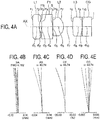
- Fig. 4A is a lens cross-sectional view of the endoscope objective optical system according to the present example.
- the endoscope objective optical system includes in order from an object side, a planoconcave negative lens L1, a flare aperture FS, a plane parallel plate F1, an aperture stop S, a planoconvex positive lens L2, a planoconvex positive lens L3, and a plane parallel plate CG.
- the plane parallel plate F1 is an infra-red absorption filter.
- the planoconvex positive lens L3 is a field lens.
- the planoconvex positive lens L3 and the plane parallel plate CG are cemented.
- d9 is an adhesive layer.
- Fig. 4B, Fig. 4C, Fig. 4D, and Fig. 4E show a spherical aberration (SA), an astigmatism (AS), a distortion (DT), and a chromatic aberration of magnification (CC) respectively, of the present example.
- SA spherical aberration
- AS astigmatism
- DT distortion
- CC chromatic aberration of magnification
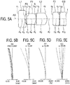
- Fig. 5A is a lens cross-sectional view of the endoscope objective optical system according to the present example.
- the endoscope objective optical system includes in order from an object side, a planoconcave negative lens L1, a flare aperture FS, a plane parallel plate F1, an aperture stop S, a planoconvex positive lens L2, a plane parallel plate F2, and a plane parallel plate CG.
- the plane parallel plate F1 is an infra-red absorption filter.
- the plane parallel plate F2 and the plane parallel plate CG are cemented.
- d9 is an adhesive layer.
- Fig. 5B, Fig. 5C, Fig. 5D, and Fig. 5E show a spherical aberration (SA), an astigmatism (AS), a distortion (DT), and a chromatic aberration of magnification (CC) respectively, of the present example.
- SA spherical aberration
- AS astigmatism
- DT distortion
- CC chromatic aberration of magnification
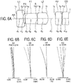
- Fig. 6A is a lens cross-sectional view of the endoscope objective optical system according to the present example.
- the endoscope objective optical system includes in order from an object side, a planoconcave negative lens L1, a flare aperture FS, a plane parallel plate F1, an aperture stop S, a planoconvex positive lens L2, a plane parallel plate F2, and a plane parallel plate CG.
- the plane parallel plate F1 is an infra-red absorption filter.
- the plane parallel plate F2 and the plane parallel plate CG are cemented.
- d9 is an adhesive layer.
- Fig. 6B, Fig. 6C, Fig. 6D, and Fig. 6E show a spherical aberration (SA), an astigmatism (AS), a distortion (DT), and a chromatic aberration of magnification (CC) respectively, of the present example.
- SA spherical aberration
- AS astigmatism
- DT distortion
- CC chromatic aberration of magnification
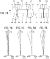
- Fig. 7A is a lens cross-sectional view of the endoscope objective optical system according to the present example.
- the endoscope objective optical system includes in order from an object side, a planoconcave negative lens L1, a flare aperture FS, a plane parallel plate F1, an aperture stop S, a planoconvex positive lens L2, a plane parallel plate F2, and a plane parallel plate CG.
- the plane parallel plate F1 is an infra-red absorption filter.
- the plane parallel plate F2 and the plane parallel plate CG are cemented.
- d9 is an adhesive layer.
- Fig. 7B, Fig. 7C, Fig. 7D, and Fig. 7E show a spherical aberration (SA), an astigmatism (AS), a distortion (DT), and a chromatic aberration of magnification (CC) respectively, of the present example.
- SA spherical aberration
- AS astigmatism
- DT distortion
- CC chromatic aberration of magnification
- Fig. 8A is a lens cross-sectional view of the endoscope objective optical system according to the present example.
- the endoscope objective optical system includes in order from an object side, a planoconcave negative lens L1, a flare aperture FS, a plane parallel plate F1, an aperture stop S, a planoconvex positive lens L2, a plane parallel plate F2, and a plane parallel plate CG.
- the plane parallel plate F1 is an infra-red absorption filter.
- the plane parallel plate F2 and the plane parallel plate CG are cemented.
- d9 is an adhesive layer.
- Fig. 8B, Fig. 8C, Fig. 8D, and Fig. 8E show a spherical aberration (SA), an astigmatism (AS), a distortion (DT), and a chromatic aberration of magnification (CC) respectively, of the present example.
- SA spherical aberration
- AS astigmatism
- DT distortion
- CC chromatic aberration of magnification
- Fig. 9A is lens cross-sectional view of the endoscope objective optical system according to the present example.
- the endoscope objective optical system includes in order from an object side, a planoconcave negative lens L1, a flare aperture FS, a plane parallel plate F1, an aperture stop S, a planoconvex positive lens L2, a plane parallel plate F2, and a plane parallel plate CG.
- the plane parallel plate F1 is an infra-red absorption filter.
- the plane parallel plate F2 and the plane parallel plate CG are cemented.
- d9 is an adhesive layer.
- Fig. 9B, Fig. 9C, Fig. 9D, and Fig. 9E show a spherical aberration (SA), an astigmatism (AS), a distortion (DT), and a chromatic aberration of magnification (CC) respectively, of the present example.
- SA spherical aberration
- AS astigmatism
- DT distortion
- CC chromatic aberration of magnification
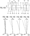
- Fig. 10A is a lens cross-sectional view of the endoscope objective optical system according to the present example.
- the endoscope objective optical system includes in order from an object side, a planoconcave negative lens L1, a flare aperture FS, a plane parallel plate F1, an aperture stop S, a planoconvex positive lens L2, a plane parallel plate F2, and a plane parallel plate CG.
- the plane parallel plate F1 is an infra-red absorption filter.
- the plane parallel plate F2 and the plane parallel plate CG are cemented.
- d9 is an adhesive layer.
- Fig. 10B, Fig. 10C, Fig. 10D, and Fig. 10E show a spherical aberration (SA), an astigmatism (AS), a distortion (DT), and a chromatic aberration of magnification (CC) respectively, of the present example.
- SA spherical aberration
- AS astigmatism
- DT distortion
- CC chromatic aberration of magnification
- Fig. 11A is a lens cross-sectional view of the endoscope objective optical system according to the present example.
- the endoscope objective optical system includes in order from an object side, a planoconcave negative lens L1, a flare aperture FS, a plane parallel plate F1, an aperture stop S, a planoconvex positive lens L2, a planoconvex positive lens L3, and a plane parallel plate CG.
- the plane parallel plate F1 is an infra-red absorption filter.
- the planoconvex positive lens L3 is a field lens.
- the planoconvex positive lens L3 and the plane parallel plate CG are cemented.
- d9 is an adhesive layer.
- Fig. 11B, Fig. 11C, Fig. 11D, and Fig. 11E show a spherical aberration (SA), an astigmatism (AS), a distortion (DT), and a chromatic aberration of magnification (CC) respectively, of the present example.
- SA spherical aberration
- AS astigmatism
- DT distortion
- CC chromatic aberration of magnification
- r denotes radius of curvature of each lens surface
- d denotes a distance between respective lens surfaces
- ne denotes a refractive index of each lens for a e-line
- vd denotes an Abbe number for each lens
- Fno denotes an F number
- ⁇ denotes a half angle of view
- IH denotes an image height
- ER denotes an effective diameter
- FS denotes a flare aperture
- S denotes an aperture stop.
- T650 is an internal transmittance of the absorption-type filter at 650 nm.
- the present invention is useful for an endoscope objective optical system resistant to a temperature change at the time of autoclave, which prevents the halation due to laser light, and in which an overall length of the optical system is short and the processing and assembling of lenses is easy.
Landscapes
- Health & Medical Sciences (AREA)
- Life Sciences & Earth Sciences (AREA)
- Physics & Mathematics (AREA)
- Surgery (AREA)
- Optics & Photonics (AREA)
- Biomedical Technology (AREA)
- Public Health (AREA)
- Nuclear Medicine, Radiotherapy & Molecular Imaging (AREA)
- Pathology (AREA)
- Radiology & Medical Imaging (AREA)
- Veterinary Medicine (AREA)
- Engineering & Computer Science (AREA)
- Heart & Thoracic Surgery (AREA)
- Biophysics (AREA)
- Molecular Biology (AREA)
- Medical Informatics (AREA)
- Animal Behavior & Ethology (AREA)
- General Health & Medical Sciences (AREA)
- General Physics & Mathematics (AREA)
- Astronomy & Astrophysics (AREA)
- Toxicology (AREA)
- Lenses (AREA)
- Endoscopes (AREA)
Abstract
Description
- The present invention relates to an endoscope objective optical system, and particularly to an electronic endoscope for a medical application, and more particularly to an endoscope objective optical system that is suitable for autoclave sterilization and a treatment using laser light.
- In an endoscope for a medical purpose, Small-sizing of an inserting portion that is to be inserted into the body has heretofore been necessary for realizing minimally invasive diagnosis and treatment upon reducing the stress on a patient. For small-sizing of the inserting portion, small-sizing of an overall length and an outer diameter of a front-end optical system is indispensable. However, with small-sizing of an optical system, a workability of an optical element is degraded, and assembling thereof also becomes difficult. As a result, the productivity is degraded.
- Moreover, in a reusable endoscope, cleansing and sterilization of the endoscope becomes significant. As a method of cleansing and sterilization, autoclave sterilization for example is a simple and effective sterilization method. Therefore, it is desirable that an endoscope to be reused is suitable for the autoclave sterilization.
- On the other hand, in the autoclave sterilization, an instrument is kept in a high-temperature and high-pressure water-vapor atmosphere, and bacteria adhered are annihilated. With respect to optical elements of the endoscope, a coefficient of thermal expansion differs for a holding frame and a glass material. For such reason, in a case of carrying out the autoclave sterilization of the instrument, due to a change in temperature at the time of autoclave, the glass material may be subjected to a substantial stress, and be damaged. For this, it is desirable that the optical element has a durability to resist the autoclave.
- Furthermore, there are cases in which an endoscope is to be used for a treatment by laser light, such as a urinary-calculus treatment. In this case, when crushing light such as Nd-YAG laser (neodymium yttrium aluminum garnet, wavelength 1064 nm) to be irradiated to the urinary calculus is incident on an image pickup element, halation of an endoscope image occurs.
- Moreover, for verifying an irradiation position of laser light for crushing, sometimes laser light of a wavelength of a visible-light region such as a wavelength close to an infra-red region is to be irradiated as laser light for target. In this case, when the laser light for target is incident on an image pickup element, halation of an endoscope image occurs.
- For preventing such halation of an endoscope image, it is effective to provide a cut filter having an adequate optical density to an optical system. For this, a filter that cuts laser light of a predetermined wavelength region, which is a cause of halation, is to be inserted into an optical path.
- Here, cut filters are broadly divided into reflection-type cut filters and absorption-type cut filters. The reflection-type cut filter reflects light of a predetermined wavelength, and does not let to pass through. In a case of using the reflection-type cut filter, light reflected becomes a cause of halation which is optically undesirable.
- Whereas, the absorption-type cut filter absorbs light of a predetermined band by a filter. Therefore, the absorption-type cut filter does not give rise to reflected light that is unnecessary. Consequently, for preventing halation, it is desirable to dispose an absorption-type cut filter having an adequate optical density in an optical path of the optical system.
- For such reasons, it is desirable that an endoscope objective optical system has a mechanical durability at the time of autoclave, and includes an absorption-type cut filter having an adequate thickness for preventing halation due to laser light, thereby realizing a compact arrangement with favorable productivity.
- Arrangements disclosed in Patent literatures 1, 2, and 3 are examples of an arrangement of an endoscope objective optical system in which an optical element is small-sized, and a filter that cuts predetermined wavelength regions is disposed.
-
- Patent Literature 1: Japanese Patent Application Laid-open Publication No.
2008-262193 - Patent Literature 2: Japanese Patent Application Laid-open Publication No.
2009-294494 - Patent Literature 3: Japanese Patent Application Laid-open Publication No.
2009-288682 - An objective lens for a small-size endoscope has been disclosed in Patent Literature 1. Patent Literature 1 is regarding a technology related to a small-size optical system with favorable productivity. The technology regulates a power distribution for each lens group, and an outer diameter and a curvature of an element.
- However, in Patent Literature 1, shortening of an overall length which is significant for small-sizing of an inserting portion of the endoscope has not been taken into consideration. Moreover, in a reusable endoscope objective optical system, cleansing and sterilization of the endoscope is necessary. For this, it is preferable that an object-side surface of a first lens nearest to object be a flat surface which is easy to clean. In an arrangement in Patent Literature 1, when an object-side surface of a first lens is let to be a flat surface, a cover glass is necessary. Consequently, the overall length becomes long.
- Furthermore, for workability and productivity of the optical system, in addition to parameters such as the outer diameter and curvature, and the power distribution, a relationship of a thickness and an outer diameter of an optical element and a relationship of a length of a lens group and the overall length become significant parameters. Since, the thickness of the optical element and the length of lens group have not been taken into consideration in Patent Literature 1, it is inadequate as a technology to realize a small-size optical system with high productivity.
- A small-size optical system including two groups having a positive refractive power, which enables inserting of an infra-red absorption filter while maintaining a favorable workability has been disclosed in Patent Literature 2.
- For preventing halation due to laser light, it is desirable that the infra-red absorption-type filter has an adequate optical density. When an adequate optical density is to be achieved in an absorption filter, a thickness of the infra-red absorption-type filter becomes large. Consequently, in a case of realizing small-sizing of the overall optical system while maintaining an adequate thickness of the infra-red absorption-type filter, the thickness of the infra-red absorption-type filter occupying the overall length of lenses becomes large as the small-sizing progresses.
- In Patent Literature 2, in a case of inserting the infra-red absorption-type filter having an adequate thickness into an optical path, light ray height becomes high thereby making an outer diameter of the optical system large. Therefore, Patent Literature 2 is not adequate as a technology for realizing small-sizing of the optical system.
- A small-size endoscope objective optical system that is easy to process and assemble has been disclosed in Patent Literature 3. In Patent Literature 3, a thickness of each optical component being thin, the workability is degraded. Furthermore, in a case of a small-size optical system, a dimensional tolerance of an inner diameter of a frame and an outer diameter of a lens compared to a size of an optical element becomes large. Therefore, when thin optical components are used, tilting and decentering occur substantially, and sometimes an adjustment becomes necessary. For such reason, in a small-size optical system, it is preferable that the optical elements be not thin. From this point, an arrangement according to Patent Literature 3 is not adequate for realizing a small-size optical system with a favorable assemblability.
- The present invention has been made in view of the abovementioned problems, and an object of the present invention is to provide an endoscope objective optical system resistant to a temperature change at the time of autoclave, which prevents halation due to laser light, and in which an overall length of the optical system is short and the processing and assembling of lenses is easy.
- To solve the abovementioned problems, and to achieve the object, the present invention is an endoscope objective optical system that is to be combined with a solid image pickup element, comprising in order from an object side, a planoconcave negative lens, an absorption-type filter, an aperture stop, and a planoconvex positive lens, wherein
the following conditional expression (1) is satisfied:
- tg1 denotes a length along an optical axis from an object-side surface of the planoconcave negative lens up to an image-side surface of the planoconvex positive lens, and
- tl denotes an overall length of the endoscope objective optical system.
- The present inventions shows an effect that it is possible to provide an endoscope objective optical system resistant to a temperature change at the time of autoclave, which prevents the halation due to laser light, and in which an overall length of the optical system is short and the processing and assembling of lenses is easy.
-
-
Fig. 1 is a cross-sectional view of an arrangement of an endoscope objective optical system according to an embodiment; -
Fig. 2A is a cross-sectional view of an arrangement of an endoscope objective optical system according to an example 1, andFig. 2B, Fig. 2C, Fig. 2D, and Fig. 2E are aberrations diagrams showing a spherical aberration (SA), an astigmatism (AS), a distortion (DT), and a chromatic aberration of magnification (CC) respectively; -
Fig. 3A is a cross-sectional view of an arrangement of an endoscope objective optical system according to an example 2, andFig. 3B, Fig. 3C, Fig. 3D, and Fig. 3E are aberration diagrams showing a spherical aberration (SA), an astigmatism (AS), a distortion (DT), and a chromatic aberration of magnification (CC) respectively; -
Fig. 4A is a cross-sectional view of an arrangement of an endoscope objective optical system according to an example 3, andFig. 4B, Fig. 4C, Fig. 4D, and Fig. 4E are aberration diagrams showing a spherical aberration (SA), an astigmatism (AS), a distortion (DT), and a chromatic aberration of magnification (CC) respectively; -
Fig. 5A is a cross-sectional view of an arrangement of an endoscope objective optical system according to an example 4, andFig. 5B, Fig. 5C, Fig. 5D, and Fig. 5E are aberration diagrams showing a spherical aberration (SA), an astigmatism (AS), a distortion (DT), and a chromatic aberration of magnification (CC) respectively; -
Fig. 6A is a cross-sectional view of an arrangement of an endoscope objective optical system according to an example 5, andFig. 6B, Fig. 6C, Fig. 6D, and Fig. 6E are aberration diagrams showing a spherical aberration (SA), an astigmatism (AS), a distortion (DT), and a chromatic aberration of magnification (CC) respectively; -
Fig. 7A is a cross-sectional view of an arrangement of an endoscope objective optical system according to an example 6, andFig. 7B, Fig. 7C, Fig. 7D, and Fig. 7E are aberration diagrams showing a spherical aberration (SA), an astigmatism (AS), a distortion (DT), and a chromatic aberration of magnification (CC) respectively; -
Fig. 8A is a cross-sectional view of an arrangement of an endoscope objective optical system according to an example 7, andFig. 8B, Fig. 8C, Fig. 8D, and Fig. 8E are aberration diagrams showing a spherical aberration (SA), an astigmatism (AS), a distortion (DT), and a chromatic aberration of magnification (CC) respectively; -
Fig. 9A is a cross-sectional view of an arrangement of an endoscope objective optical system according to an example 8, andFig. 9B, Fig. 9C, Fig. 9D, and Fig. 9E are aberration diagrams showing a spherical aberration (SA), an astigmatism (AS), a distortion (DT), and a chromatic aberration of magnification (CC) respectively; -
Fig. 10A is a cross-sectional view of an arrangement of an endoscope objective optical system according to an example 9, andFig. 10B, Fig. 10C, Fig. 10D, and Fig. 10E are aberration diagrams showing a spherical aberration (SA), an astigmatism (AS), a distortion (DT), and a chromatic aberration of magnification (CC) respectively; -
Fig. 11A is a cross-sectional view of an arrangement of an endoscope objective optical system according to an example 10, andFig. 11B, Fig. 11C, Fig. 11D, and Fig. 11E are aberration diagrams showing a spherical aberration (SA), an astigmatism (AS), a distortion (DT), and a chromatic aberration of magnification (CC) respectively, and -
Fig. 12 is a diagram showing tilt of an optical element. - Embodiments of an endoscope objective optical system will be described below in detail by referring to the accompanying diagrams. However, the present invention is not restricted to the embodiments and the examples described below.
-
Fig. 1 is a cross-sectional view of a lens arrangement of an endoscope objective optical system according to an embodiment. - The present embodiment is an endoscope objective optical system that is to be combined with a solid image pickup element, which includes in order from an object side, a planoconcave negative lens L1 having a flat surface directed toward the object side, a flare aperture FS, an absorption-type filter (plane parallel plate) F1, an aperture stop S, and a planoconvex positive lens L2 having a flat surface directed toward the object side, wherein the following conditional expression (1) is satisfied:

- tg1 denotes a length along an optical axis AX from an object-side surface of the planoconcave negative lens L1 up to an image-side surface of the planoconvex positive lens L2, and
- tl denotes an overall length of the endoscope objective optical system, or in other words, a length along the optical axis AX from the object-side surface of the planoconcave negative lens L1 up to an image-side surface of the planoconcave negative lens L1.
- Parameter tg1 corresponds to a length of a portion including almost all lenses having a power. Conditional expression (1) regulates a proportion of parameter tg1 occupying the overall length.
- By letting so as not to fall below a lower limit value of conditional expression (1), a back focus of the endoscope objective optical system becomes short, and shortening of the overall length is facilitated. Moreover, a thickness of each optical element becomes large, and processing, holding, and assembling of components become easy.
- Moreover, a fact that a thickness of the optical element is thick contributes also to an improvement in durability of the optical element with respect to a thermal stress exerted from a holding frame at the time of autoclave.
- Moreover, the fact that the thickness of the optical element such as the absorption-type filter (plane parallel plate) F1 enables to cut laser light of a predetermined wavelength region by adequate absorption. Accordingly, it is possible to prevent halation of an endoscope image due to laser light for target for example.
- Furthermore, as mentioned above, when an endoscope is to be used for a treatment by laser light, such as the urinary-calculus treatment, laser light for crushing such as Nd-YAG is irradiated to a calculus. When such laser light is incident on an image pickup element, halation of an endoscope image occurs.
- Therefore, it is desirable to apply a coating of a reflecting film that reflects Nd-YAG laser light, on at least one surface of the absorption-type filter F1.
- In a case of exceeding an upper limit value of conditional expression (1), it is not possible to secure a back-focus length required for focus adjustment.
- It is preferable that the following conditional expression (1') be satisfied instead of conditional expression (1) .

- In the endoscope objective optical system of the present embodiment, it is desirable that the absorption-type filter is an infra-red absorption filter.
- For instance, sometimes, laser light of an infra-red region which is visible light, is to be used as the laser light for target. Accordingly, by cutting the laser light of the infra-red region, it is possible to reduce the halation of the endoscope image.
- Moreover, in the endoscope objective optical system of the present embodiment, it is preferable that the following conditional expressions (2), (3), and (4) are satisfied:


- tn denotes a total thickness of the planoconcave negative lens L1,
- φn denotes an outer diameter of the planoconcave negative lens L1,
- tIRCF denotes a thickness of the absorption-type filter (plane parallel plate) F,
- φIRCF denotes an outer diameter of the absorption-type filter (plane parallel plate) F,
- tp denotes a total thickness of the planoconvex positive lens L2, and
- φp denotes an outer diameter of the planoconvex positive lens L2.
- The 'total thickness' refers to a thickness of an outer peripheral portion of the optical element. The 'thickness' refers to a thickness on an optical axis of the optical element.
- Conditional expressions (2), (3), and (4) regulate a relationship of the outer diameter and the thickness of the planoconcave negative lens L1, the absorption-type filter (plane parallel plate) F1, and the planoconvex positive lens L2 respectively.
- In a case of falling below lower limit values of conditional expressions (2), (3), and (4), processing and assemblability of the optical system is deteriorated, and resistance with respect to the autoclave is also degraded.
- Moreover, in the case of falling below the lower limit values of conditional expressions (2), (3), and (4), the planoconcave negative lens L1, the absorption-type filter (plane parallel plate) F1, and the planoconvex positive lens L2 have tilting and decentering, and an astigmatism and a coma occur.
- In a case of exceeding upper limit values of conditional expressions (2), (3), and (4), it results in the overall length of the optical system becoming long.
- Moreover, in a small-size optical system, there is a clearance of about 4% of an outer diameter of an element between an optical element and a frame due to a manufacturing error. For an optical performance, it is desirable to suppress the tilting of the optical element in the lens frame due to the clearance, to be not more than 10°.
-
Fig. 12 is a diagram showing tilt of an optical element L in the form of a plane parallel plate having an outer diameter φ. For suppressing an angle α of tilt of the optical element L to be not more than 10°, a value of (a total thickness of the optical element L) / (the outer diameter φ of the optical element L) is required to be higher than 0.32. - By letting the value of (a thickness of the optical element L) / (the outer diameter φ of the optical element L), or in other words, the lower limit values of conditional expressions (2), (3), and (4), to be higher than 0.32, an adjustment of an angle of the optical element L becomes unnecessary, and the assemblability is improved. Furthermore, when the thickness is made thick with respect to the outer diameter of the optical element L, the durability with respect to stress from an outer peripheral portion exerted at the time of autoclave is also improved.
- It is more preferable that the following conditional expressions (2'), (3'), and (4') be satisfied instead of conditional expressions (2), (3), and (4):


- Moreover, in the endoscope objective optical system of the present embodiment, it is desirable that the following conditional expressions (2-1), (3-1), (4-1), and (4-2) are satisfied:



- fn denotes a focal length of the planoconcave negative lens,
- ft denotes a focal length of the overall endoscope objective optical system,
- tIRCF denotes the thickness of the absorption-type filter,
- tl denotes the overall length of the endoscope objective optical system,
- fp denotes a focal length of the planoconvex positive lens,
- tp' denotes a thickness of the planoconvex positive lens, and
- rp denotes a radius of curvature of a convex surface of the planoconvex positive lens.
- Conditional expression (2-1) regulates a power distribution of the biconcave negative lens L1 and the overall endoscope objective optical system.
- In a case of exceeding an upper limit value of conditional expression (2-1), a height of a light ray incident on a first surface on the object side of the biconcave negative lens L1 becomes high, and flare is generated.
- In a case of falling below a lower limit value of conditional expression (2-1), a curvature of a concave surface of the planoconcave negative lens L1 becomes strong, and workability of the lens is deteriorated.
- Conditional expression (3-1) regulates a relationship of the thickness of the absorption-type filter (plane parallel plate) F1 and the overall length. In the endoscope objective optical system having the abovementioned arrangement, by letting so as not to fall below a lower limit value of conditional expression (3-1), it is possible to secure an adequate thickness of the absorption-type filter. Consequently, it is possible to cut light of a wavelength region causing halation, and to prevent the halation.
- Conditional expression (4-1) regulates a power distribution of the planoconvex positive lens L2 and the overall endoscope objective optical system.
- In a case of falling below a lower limit value of conditional expression (4-1), it is not possible to secure the back-focus length required for the focus adjustment.
- In a case of exceeding an upper limit value of conditional expression (4-1), the power of the planoconvex positive lens L2 is inadequate, and the overall length of the optical system becomes long.
- Conditional expression (4-2) regulates a relationship of the thickness and the radius of curvature of the planoconvex positive lens L2. In a case of falling below a lower limit value of conditional expression (4-2) or in a case of exceeding an upper limit value of conditional expression (4-2), the centering workability of the lens is deteriorated.
- An endoscope objective optical system according to an example 1 will be described below.
Fig. 2A is a lens cross-sectional view of the endoscope objective optical system according to the present example. - In the present example, the endoscope objective optical system includes in order from an object side, a planoconcave negative lens L1, a flare aperture FS, a plane parallel plate F1, an aperture stop S, a planoconvex positive lens L2, a plane parallel plate F2, and a plane parallel plate CG.
- The plane parallel plate F1 is an infra-red absorption filter. The plane parallel plate F2 and the plane parallel plate CG are cemented. Here, d9 is an adhesive layer.
-
Fig. 2B, Fig. 2C, Fig. 2D, and Fig. 2E show a spherical aberration (SA), an astigmatism (AS), a distortion (DT), and a chromatic aberration of magnification (CC) respectively, of the present example. The aberration diagrams are for each of wavelengths 656.27 nm (C-line), 587.56 nm (d-line), 540-07 nm (e-line), 486.13 nm (F-line), and 435.83 nm (g-line). Moreover, in each diagram, FNO denotes an F-number, and 'ω' denotes a half angle of view. Similar is true for the other aberration diagrams described below. - An endoscope objective optical system according to an example 2 will be described below.
Fig. 3A is a lens cross-sectional view of the endoscope objective optical system according to the present example. - In the present example, the endoscope objective optical system includes in order from an object side, a planoconcave negative lens L1, a flare aperture FS, a plane parallel plate F1, an aperture stop S, a planoconvex positive lens L2, a planoconvex positive lens L3, and a plane parallel plate CG.
- The plane parallel plate F1 is an infra-red absorption filter. The planoconvex positive lens L3 is a field lens. The planoconvex positive lens L3 and the plane parallel plate CG are cemented. Here, d9 is an adhesive layer.
-
Fig. 3B, Fig. 3C, Fig. 3D, and Fig. 3E show a spherical aberration (SA), an astigmatism (AS), a distortion (DT), and a chromatic aberration of magnification (CC) respectively, of the present example. - An endoscope objective optical system according to an example 3 will be described below.
Fig. 4A is a lens cross-sectional view of the endoscope objective optical system according to the present example. - In the present example, the endoscope objective optical system includes in order from an object side, a planoconcave negative lens L1, a flare aperture FS, a plane parallel plate F1, an aperture stop S, a planoconvex positive lens L2, a planoconvex positive lens L3, and a plane parallel plate CG.
- The plane parallel plate F1 is an infra-red absorption filter. The planoconvex positive lens L3 is a field lens. The planoconvex positive lens L3 and the plane parallel plate CG are cemented. Here, d9 is an adhesive layer.
-
Fig. 4B, Fig. 4C, Fig. 4D, and Fig. 4E show a spherical aberration (SA), an astigmatism (AS), a distortion (DT), and a chromatic aberration of magnification (CC) respectively, of the present example. - An endoscope objective optical system according to an example 4 will be described below.
Fig. 5A is a lens cross-sectional view of the endoscope objective optical system according to the present example. - In the present example, the endoscope objective optical system includes in order from an object side, a planoconcave negative lens L1, a flare aperture FS, a plane parallel plate F1, an aperture stop S, a planoconvex positive lens L2, a plane parallel plate F2, and a plane parallel plate CG.
- The plane parallel plate F1 is an infra-red absorption filter. The plane parallel plate F2 and the plane parallel plate CG are cemented. Here, d9 is an adhesive layer.
-
Fig. 5B, Fig. 5C, Fig. 5D, and Fig. 5E show a spherical aberration (SA), an astigmatism (AS), a distortion (DT), and a chromatic aberration of magnification (CC) respectively, of the present example. - An endoscope objective optical system according to an example 5 will be described below.
Fig. 6A is a lens cross-sectional view of the endoscope objective optical system according to the present example. - In the present example, the endoscope objective optical system includes in order from an object side, a planoconcave negative lens L1, a flare aperture FS, a plane parallel plate F1, an aperture stop S, a planoconvex positive lens L2, a plane parallel plate F2, and a plane parallel plate CG.
- The plane parallel plate F1 is an infra-red absorption filter. The plane parallel plate F2 and the plane parallel plate CG are cemented. Here, d9 is an adhesive layer.
-
Fig. 6B, Fig. 6C, Fig. 6D, and Fig. 6E show a spherical aberration (SA), an astigmatism (AS), a distortion (DT), and a chromatic aberration of magnification (CC) respectively, of the present example. - An endoscope objective optical system according to an example 6 will be described below.
Fig. 7A is a lens cross-sectional view of the endoscope objective optical system according to the present example. - In the present example, the endoscope objective optical system includes in order from an object side, a planoconcave negative lens L1, a flare aperture FS, a plane parallel plate F1, an aperture stop S, a planoconvex positive lens L2, a plane parallel plate F2, and a plane parallel plate CG.
- The plane parallel plate F1 is an infra-red absorption filter. The plane parallel plate F2 and the plane parallel plate CG are cemented. Here, d9 is an adhesive layer.
-
Fig. 7B, Fig. 7C, Fig. 7D, and Fig. 7E show a spherical aberration (SA), an astigmatism (AS), a distortion (DT), and a chromatic aberration of magnification (CC) respectively, of the present example. - An endoscope objective optical system according to an example 7 will be described below.
Fig. 8A is a lens cross-sectional view of the endoscope objective optical system according to the present example. - In the present example, the endoscope objective optical system includes in order from an object side, a planoconcave negative lens L1, a flare aperture FS, a plane parallel plate F1, an aperture stop S, a planoconvex positive lens L2, a plane parallel plate F2, and a plane parallel plate CG.
- The plane parallel plate F1 is an infra-red absorption filter. The plane parallel plate F2 and the plane parallel plate CG are cemented. Here, d9 is an adhesive layer.
-
Fig. 8B, Fig. 8C, Fig. 8D, and Fig. 8E show a spherical aberration (SA), an astigmatism (AS), a distortion (DT), and a chromatic aberration of magnification (CC) respectively, of the present example. - An endoscope objective optical system according to an example 8 will be described below.
Fig. 9A is lens cross-sectional view of the endoscope objective optical system according to the present example. - In the present example, the endoscope objective optical system includes in order from an object side, a planoconcave negative lens L1, a flare aperture FS, a plane parallel plate F1, an aperture stop S, a planoconvex positive lens L2, a plane parallel plate F2, and a plane parallel plate CG.
- The plane parallel plate F1 is an infra-red absorption filter. The plane parallel plate F2 and the plane parallel plate CG are cemented. Here, d9 is an adhesive layer.
-
Fig. 9B, Fig. 9C, Fig. 9D, and Fig. 9E show a spherical aberration (SA), an astigmatism (AS), a distortion (DT), and a chromatic aberration of magnification (CC) respectively, of the present example. - An endoscope objective optical system according to an example 9 will be described below.
Fig. 10A is a lens cross-sectional view of the endoscope objective optical system according to the present example. - In the present example, the endoscope objective optical system includes in order from an object side, a planoconcave negative lens L1, a flare aperture FS, a plane parallel plate F1, an aperture stop S, a planoconvex positive lens L2, a plane parallel plate F2, and a plane parallel plate CG.
- The plane parallel plate F1 is an infra-red absorption filter. The plane parallel plate F2 and the plane parallel plate CG are cemented. Here, d9 is an adhesive layer.
-
Fig. 10B, Fig. 10C, Fig. 10D, and Fig. 10E show a spherical aberration (SA), an astigmatism (AS), a distortion (DT), and a chromatic aberration of magnification (CC) respectively, of the present example. - An endoscope objective optical system according to an example 10 will be described below.
Fig. 11A is a lens cross-sectional view of the endoscope objective optical system according to the present example. - In the present example, the endoscope objective optical system includes in order from an object side, a planoconcave negative lens L1, a flare aperture FS, a plane parallel plate F1, an aperture stop S, a planoconvex positive lens L2, a planoconvex positive lens L3, and a plane parallel plate CG.
- The plane parallel plate F1 is an infra-red absorption filter. The planoconvex positive lens L3 is a field lens. The planoconvex positive lens L3 and the plane parallel plate CG are cemented. Here, d9 is an adhesive layer.
-
Fig. 11B, Fig. 11C, Fig. 11D, and Fig. 11E show a spherical aberration (SA), an astigmatism (AS), a distortion (DT), and a chromatic aberration of magnification (CC) respectively, of the present example. - Numerical data of each example described above is shown below. In Surface data, r denotes radius of curvature of each lens surface, d denotes a distance between respective lens surfaces, ne denotes a refractive index of each lens for a e-line, vd denotes an Abbe number for each lens, Fno denotes an F number, ω denotes a half angle of view, and IH denotes an image height. Moreover, ER denotes an effective diameter, FS denotes a flare aperture, and S denotes an aperture stop. Here, T650 is an internal transmittance of the absorption-type filter at 650 nm.
-
Surface data Surface no. r d ne vd ER 1 ∞ 0.200 1.77066 71.79 0.80 2 0.300 0.100 3 (FS) ∞ 0.030 0.30 4 ∞ 0.450 1.52300 65.13 0.50 5 (S) ∞ 0.010 0.17 6 ∞ 0.410 1.88815 40.76 0.55 7 -0.427 0.474 8 ∞ 0.300 1.51825 64.14 0.62 9 ∞ 0.020 1.50688 64.00 0.62 10 ∞ 0.300 1.61350 50.49 0.62 Image plane ∞ Various data Focal length (mm) 0.334 Angle of view (°) 90.6 Fno 4.186 T650 (%) 12.28 tl (mm) 2.29 -
Surface data Surface no. r d ne vd ER 1 ∞ 0.200 1.77066 71.79 0.80 2 0.300 0.090 3 (FS) ∞ 0.030 0.30 4 ∞ 0.450 1.52300 65.13 0.50 5 (S) ∞ 0.010 0.16 6 ∞ 0.390 1.88815 40.76 0.55 7 -0.459 0.520 8 0.951 0.340 1.51825 64.14 0.65 9 ∞ 0.020 1.50688 64.00 0.65 10 ∞ 0.300 1.61350 50.49 0.65 Image plane ∞ Various data Focal length (mm) 0.310 Angle of view (°) 96.9 Fno 4.079 T650 (%) 12.28 tl (mm) 2.35 -
Surface data Surface no. r d ne vd ER 1 ∞ 0.210 1.77066 71.79 0.80 2 0.408 0.050 3 (FS) ∞ 0.030 0.32 4 ∞ 0.360 1.52300 65.13 0.80 5 (S) ∞ 0.010 0.13 6 ∞ 0.350 1. 88815 40.76 0.60 7 -0.374 0.300 8 2.963 0.300 1.51825 64.14 0.62 9 ∞ 0.020 1.50688 64.00 0.62 10 ∞ 0.300 1.61350 50.49 0.62 Image plane ∞ Various data Focal length (mm) 0.336 Angle of view (°) 87.5 Fno 4.182 T650 (%) 18.67 tl (mm) 1.93 -
Surface data Surface no. r d ne vd ER 1 ∞ 0.300 1.77066 71.79 0.80 2 0.540 0.050 3 (FS) ∞ 0.030 0.36 4 ∞ 0.450 1.52300 65.13 0.50 5 (S) ∞ 0.010 0.17 6 ∞ 0.500 1.88815 40.76 0.55 7 -0.390 0.271 8 00 0.300 1.51825 64.14 0.62 9 00 0.020 1.50688 64.00 0.62 10 00 0.300 1.61350 50.49 0.62 Image plane ∞ Various data Focal length (mm) 0.337 Angle of view (°) 87.7 Fno 3.082 T650 (%) 12.28 tl (mm) 2.23 -
Surface data Surface no. r d ne vd ER 1 ∞ 0.300 1.77066 71.79 0.80 2 0.492 0.070 3 (FS) ∞ 0.030 0.40 4 ∞ 0.570 1.52300 65.13 0.50 5 (S) ∞ 0.010 0.14 6 ∞ 0.500 1.88815 40.76 0.55 7 -0.424 0.346 8 ∞ 0.300 1.51825 64.14 0.62 9 ∞ 0.020 1.50688 64.00 0.62 10 ∞ 0.300 1.61350 50.49 0.62 Image plane ∞ Various data Focal length (mm) 0.335 Angle of view (°) 87.7 Fno 4.214 T650 (%) 7.02 tl (mm) 2.45 -
Surface data Surface no. r d ne vd ER 1 ∞ 0.200 1.77066 71.79 0.80 2 0.476 0.070 3 (FS) ∞ 0.030 0.42 4 ∞ 0.670 1.52300 65.13 0.50 5 (S) ∞ 0.010 0.15 6 ∞ 0.390 1.88815 40.76 0.55 7 -0.428 0.361 8 ∞ 0.300 1.51825 64.14 0.62 9 ∞ 0.020 1.50688 64.00 0.62 10 ∞ 0.300 1.61350 50.49 0.62 Image plane ∞ Various data Focal length (mm) 0.334 Angle of view (°) 87.2 Fno 4.213 T650 (%) 4.40 tl (mm) 2.35 -
Surface data Surface no. r d ne vd ER 1 ∞ 0.200 1.77066 71.79 0.60 2 0.270 0.090 3 (FS) ∞ 0.030 0.28 4 ∞ 0.450 1.52300 65.13 0.50 5 (S) ∞ 0.010 0.18 6 ∞ 0.390 1.88815 40.76 0.55 7 -0.425 0.554 8 ∞ 0.300 1.51825 64.14 0.65 9 ∞ 0.020 1.50688 64.00 0.65 10 ∞ 0.300 1.61350 50.49 0.65 Image plane 00 Various data Focal length (mm) 0.333 Angle of view (°) 87.7 Fno 4.133 T650 (%) 12.28 tl (mm) 2.34 -
Surface data Surface no. r d ne vd ER 1 ∞ 0.480 2.01169 28.27 0.60 2 0.44 0.050 3 (FS) ∞ 0.030 0.24 4 ∞ 0.450 1.52300 65.13 0.50 5 (S) ∞ 0.010 0.20 6 00 0.390 1.80922 39.59 0.55 7 -0.416 0.650 8 ∞ 0.300 1.51825 64.14 0.65 9 ∞ 0.020 1.50688 64.00 0.65 10 ∞ 0.300 1.61350 50.49 0.65 Image plane 00 Various data Focal length (mm) 0.428 Angle of view (°) 66.0 Fno 4.063 T650 (%) 12.28 tl (mm) 2.68 -
Surface data Surface no. r d ne vd ER 1 ∞ 0.300 2.01169 28.27 0.80 2 0.718 0.050 3 (FS) ∞ 0.030 0.36 4 ∞ 0.430 1.52300 65.13 0.50 5 (S) ∞ 0.010 0.12 6 ∞ 0.550 2.01169 28.27 0.50 7 -0.446 0.273 8 ∞ 0.300 1.51825 64.14 0.62 9 ∞ 0.020 1.50688 64.00 0.62 10 ∞ 0.300 1.61350 50.49 0.62 Image plane ∞ Various data Focal length (mm) 0.342 Angle of view (°) 87.5 Fno 4.349 T650 (%) 13.48 tl (mm) 2.26 -
Surface data Surface no. r d ne vd ER 1 ∞ 0.200 1.77066 71.79 0.80 2 0.420 0.070 3 (FS) ∞ 0.030 0.42 4 ∞ 0.560 1.52300 65.13 0.50 5 (S) ∞ 0.010 0.15 6 ∞ 0.390 1.88815 40.76 0.55 7 -0.440 0.410 8 2.100 0.300 1.51825 64.14 0.62 9 ∞ 0.020 1.50688 64.00 0.62 10 ∞ 0.300 1.61350 50.49 0.62 Image plane ∞ Various data Focal length (mm) 0.333 Angle of view (°) 87.7 Fno 4.182 T650 (%) 7.35 tl (mm) 2.29 - Values of conditional expressions in each example are given below.
Conditional expression Example1 Example2 Example3 Example4 (1) tg1/tl 0.52 0.50 0.52 0.60 (2) tn/ϕn 0.38 0.36 0.33 0.44 (3) tIRCF/ϕIRCF 0.90 0.90 0.45 0.90 (4) tp/ϕp 0.56 0.54 0.33 0.70 (2-1) |fn/ft| 1.17 1.26 1.58 2.08 (3-1) tIRCF/tl 0.20 0.19 0.19 0.20 (4-1) |fp/ft| 1.44 1.67 1.25 1.30 (4-2) |tp'/rp| 0.96 0.85 0.94 1.28 Conditional expression Example5 Example6 Example7 (1) tg1/tl 0.61 0.58 0.50 (2) tn/ϕn 0.46 0.53 0.53 (3) tIRCF/ϕIRCF 1.14 1.34 0.90 (4) tp/ϕp 0.72 0.71 0.71 (2-1) |fn/ft| 1.91 1.85 1.05 (3-1) tIRCF/tl 0.23 0.28 0.19 (4-1) |fp/ft| 1.43 1.44 1.44 (4-2) |tp'/rp| 1.18 0.91 0.92 Conditional expression Example8 Example9 Example10 (1) tg1/tl 0.53 0.61 0.55 (2) tn/ϕn 0.52 0.95 0.53 (3) tIRCF/ϕIRCF 0.90 0.86 1.12 (4) tp/ϕp 0.71 1.10 0.71 (2-1) |fn/ft| 1. 02 2.07 1.63 (3-1) tIRCF/tl 0.17 0.19 0.24 (4-1) |fp/ft| 1.20 1.29 1.49 (4-2) |tp'/rp| 0.94 1.23 0.89 - The embodiment and various examples of the present invention are described above. However, the present invention is not restricted to these embodiment and examples, and embodiments formed by combining arrangement of these embodiment and examples without departing from the scope of the present invention are also included in the category of the present invention.
- Thus, the present invention is useful for an endoscope objective optical system resistant to a temperature change at the time of autoclave, which prevents the halation due to laser light, and in which an overall length of the optical system is short and the processing and assembling of lenses is easy.
-
- L1, L2
- lens
- F1, F2, CG
- plane parallel plate
- FS
- flare aperture
- S
- aperture stop
- AX
- optical axis
- I
- image plane
Claims (4)
- An endoscope objective optical system that is to be combined with a solid image pickup element, comprising in order from an object side:a planoconcave negative lens;an absorption-type filter;an aperture stop; anda planoconvex positive lens, whereinthe following conditional expression (1) is satisfied:
 tg1 denotes a length along an optical axis from an object-side surface of the planoconcave negative lens up to an image-side surface of the planoconvex positive lens, andtl denotes an overall length of the endoscope objective optical system.
 - The endoscope objective optical system according to claim 1, wherein the absorption-type filter is an infra-red absorption filter.
- The endoscope objective optical system according to claim 1 or 2, wherein the following conditional expressions (2), (3), and (4) are satisfied:


 tn denotes a total thickness of the planoconcave negative lens,φn denotes an outer diameter of the planoconcave negative lens,tIRCF denotes a thickness of the absorption-type filter,φIRCF denotes an outer diameter of the absorption-type filter,tp denotes a total thickness of the planoconvex positive lens, andφp denotes an outer diameter of the planoconvex positive lens.
 - The endoscope objective optical system according to any one of claims 1 to 3, wherein the following conditional expressions (2-1), (3-1), (4-1), and (4-2) are satisfied:


 fn denotes a focal length of the planoconcave negative lens,ft denotes a focal length of the overall endoscope objective optical system,tIRCF denotes a thickness of the absorption-type filter,tl denotes the overall length of the endoscope objective optical system,fp denotes a focal length of the planoconvex positive lens,tp' denotes a thickness of the planoconvex positive lens, andrp denotes a radius of curvature of a convex surface of the planoconvex positive lens.
Applications Claiming Priority (2)
| Application Number | Priority Date | Filing Date | Title |
|---|---|---|---|
| JP2015230522 | 2015-11-26 | ||
| PCT/JP2016/080773 WO2017090342A1 (en) | 2015-11-26 | 2016-10-18 | Endoscope objective optical system |
Publications (1)
| Publication Number | Publication Date |
|---|---|
| EP3382438A1 true EP3382438A1 (en) | 2018-10-03 |
Family
ID=58763402
Family Applications (1)
| Application Number | Title | Priority Date | Filing Date |
|---|---|---|---|
| EP16868291.2A Withdrawn EP3382438A1 (en) | 2015-11-26 | 2016-10-18 | Endoscope objective optical system |
Country Status (5)
| Country | Link |
|---|---|
| US (1) | US10809523B2 (en) |
| EP (1) | EP3382438A1 (en) |
| JP (1) | JP6227201B2 (en) |
| CN (1) | CN108139567B (en) |
| WO (1) | WO2017090342A1 (en) |
Families Citing this family (5)
| Publication number | Priority date | Publication date | Assignee | Title |
|---|---|---|---|---|
| US10620424B1 (en) * | 2016-09-16 | 2020-04-14 | Precision Optics Corporation, Inc. | Lens for use with imaging sensors |
| JP6463566B1 (en) * | 2017-06-02 | 2019-02-06 | オリンパス株式会社 | Endoscope objective optical system, endoscope and endoscope system |
| CN110251049B (en) * | 2019-06-14 | 2021-05-04 | 江西联创电子有限公司 | Endoscope lens |
| CN110596878B (en) * | 2019-10-14 | 2021-11-16 | 南京大学 | Double-lens microscope system with ultra-short focal length |
| JPWO2024070754A1 (en) * | 2022-09-29 | 2024-04-04 |
Family Cites Families (13)
| Publication number | Priority date | Publication date | Assignee | Title |
|---|---|---|---|---|
| JP2558333B2 (en) * | 1988-09-06 | 1996-11-27 | オリンパス光学工業株式会社 | Endoscope objective optical system |
| JPH08286128A (en) * | 1995-04-17 | 1996-11-01 | Olympus Optical Co Ltd | Objective optical system for endoscope |
| JPH09325285A (en) * | 1996-05-31 | 1997-12-16 | Olympus Optical Co Ltd | Endoscopic objective lens |
| US6252723B1 (en) * | 1998-03-03 | 2001-06-26 | Olympus Optical Co., Ltd. | Objective optical system |
| JP2001059937A (en) * | 1999-08-24 | 2001-03-06 | Olympus Optical Co Ltd | Objective lens |
| JP4472130B2 (en) * | 2000-07-14 | 2010-06-02 | オリンパス株式会社 | Endoscope device |
| US7280283B1 (en) * | 2006-05-17 | 2007-10-09 | Olympus Corporation | Endoscopic objective optical system, and imaging system using the same |
| US7869140B2 (en) | 2007-04-13 | 2011-01-11 | Karl Storz Imaging, Inc. | Objective lens design for miniature endoscope |
| JP2009288682A (en) * | 2008-05-30 | 2009-12-10 | Olympus Medical Systems Corp | Objective optical system for endoscopes |
| JP5107144B2 (en) | 2008-06-06 | 2012-12-26 | オリンパスメディカルシステムズ株式会社 | Objective optical system and endoscope |
| JP5558058B2 (en) * | 2008-09-19 | 2014-07-23 | オリンパスメディカルシステムズ株式会社 | Endoscopic endoscope |
| CN101726832B (en) * | 2008-10-31 | 2011-09-07 | 比亚迪股份有限公司 | Lens assembly of endoscope |
| JP5706590B2 (en) * | 2012-07-23 | 2015-04-22 | 富士フイルム株式会社 | Endoscope objective lens and endoscope |
-
2016
- 2016-10-18 WO PCT/JP2016/080773 patent/WO2017090342A1/en not_active Ceased
- 2016-10-18 CN CN201680059435.0A patent/CN108139567B/en active Active
- 2016-10-18 EP EP16868291.2A patent/EP3382438A1/en not_active Withdrawn
- 2016-10-18 JP JP2017525422A patent/JP6227201B2/en active Active
-
2018
- 2018-04-17 US US15/955,227 patent/US10809523B2/en active Active
Also Published As
| Publication number | Publication date |
|---|---|
| CN108139567A (en) | 2018-06-08 |
| JPWO2017090342A1 (en) | 2017-11-24 |
| US20180231763A1 (en) | 2018-08-16 |
| JP6227201B2 (en) | 2017-11-08 |
| US10809523B2 (en) | 2020-10-20 |
| WO2017090342A1 (en) | 2017-06-01 |
| CN108139567B (en) | 2020-09-22 |
Similar Documents
| Publication | Publication Date | Title |
|---|---|---|
| US10809523B2 (en) | Endoscope objective optical system | |
| JP6313241B2 (en) | Endoscope objective lens and endoscope | |
| JP5031930B2 (en) | Endoscope objective lens and endoscope using the same | |
| JP5587513B2 (en) | Objective optical system and endoscope apparatus using the same | |
| EP3306369A1 (en) | Endoscope objective optical system | |
| EP3312652A1 (en) | Endoscope objective optical system | |
| EP3508900A1 (en) | Objective optical system for endoscope | |
| JPH08122632A (en) | Objective for endoscope | |
| EP2784563B1 (en) | Endoscope objective optical system | |
| EP3214475A1 (en) | Objective optical system for endoscope | |
| CN103282817B (en) | Objective lens optical system for endoscope | |
| US9939627B2 (en) | Objective optical system for endoscope | |
| US10054783B2 (en) | Endoscope objective optical system | |
| CN109416459B (en) | Endoscope Objective Optical System | |
| JP7113783B2 (en) | Objective optical system for endoscope and endoscope | |
| EP2662718B1 (en) | Optical system for endoscope | |
| EP3159725A1 (en) | Objective optical system for endoscope | |
| EP2618196A1 (en) | Objective optical system for endoscope | |
| US9804381B2 (en) | Endoscope objective optical system | |
| JPH09292571A (en) | Microscope objective lens | |
| JPH08179226A (en) | Objective optical system for endoscope | |
| WO2021079684A1 (en) | Objective optical system for endoscope, and endoscope | |
| JP2000187155A (en) | Objective optical system for endoscope | |
| JPH1114902A (en) | Endoscope objective optical system | |
| JP3590439B2 (en) | Endoscope objective lens |
Legal Events
| Date | Code | Title | Description |
|---|---|---|---|
| STAA | Information on the status of an ep patent application or granted ep patent |
Free format text: STATUS: THE INTERNATIONAL PUBLICATION HAS BEEN MADE |
|
| PUAI | Public reference made under article 153(3) epc to a published international application that has entered the european phase |
Free format text: ORIGINAL CODE: 0009012 |
|
| STAA | Information on the status of an ep patent application or granted ep patent |
Free format text: STATUS: REQUEST FOR EXAMINATION WAS MADE |
|
| 17P | Request for examination filed |
Effective date: 20180607 |
|
| AK | Designated contracting states |
Kind code of ref document: A1 Designated state(s): AL AT BE BG CH CY CZ DE DK EE ES FI FR GB GR HR HU IE IS IT LI LT LU LV MC MK MT NL NO PL PT RO RS SE SI SK SM TR |
|
| AX | Request for extension of the european patent |
Extension state: BA ME |
|
| DAV | Request for validation of the european patent (deleted) | ||
| DAX | Request for extension of the european patent (deleted) | ||
| STAA | Information on the status of an ep patent application or granted ep patent |
Free format text: STATUS: THE APPLICATION IS DEEMED TO BE WITHDRAWN |
|
| 18D | Application deemed to be withdrawn |
Effective date: 20190501 |