EP3382403A1 - Physical quantity sensor, electronic device, and vehicle - Google Patents
Physical quantity sensor, electronic device, and vehicle Download PDFInfo
- Publication number
- EP3382403A1 EP3382403A1 EP18163898.2A EP18163898A EP3382403A1 EP 3382403 A1 EP3382403 A1 EP 3382403A1 EP 18163898 A EP18163898 A EP 18163898A EP 3382403 A1 EP3382403 A1 EP 3382403A1
- Authority
- EP
- European Patent Office
- Prior art keywords
- beam portion
- physical quantity
- quantity sensor
- movable body
- fixed
- Prior art date
- Legal status (The legal status is an assumption and is not a legal conclusion. Google has not performed a legal analysis and makes no representation as to the accuracy of the status listed.)
- Granted
Links
Images





Classifications
-
- G—PHYSICS
- G01—MEASURING; TESTING
- G01P—MEASURING LINEAR OR ANGULAR SPEED, ACCELERATION, DECELERATION, OR SHOCK; INDICATING PRESENCE, ABSENCE, OR DIRECTION, OF MOVEMENT
- G01P15/00—Measuring acceleration; Measuring deceleration; Measuring shock, i.e. sudden change of acceleration
- G01P15/02—Measuring acceleration; Measuring deceleration; Measuring shock, i.e. sudden change of acceleration by making use of inertia forces using solid seismic masses
- G01P15/08—Measuring acceleration; Measuring deceleration; Measuring shock, i.e. sudden change of acceleration by making use of inertia forces using solid seismic masses with conversion into electric or magnetic values
- G01P15/125—Measuring acceleration; Measuring deceleration; Measuring shock, i.e. sudden change of acceleration by making use of inertia forces using solid seismic masses with conversion into electric or magnetic values by capacitive pick-up
-
- B—PERFORMING OPERATIONS; TRANSPORTING
- B81—MICROSTRUCTURAL TECHNOLOGY
- B81B—MICROSTRUCTURAL DEVICES OR SYSTEMS, e.g. MICROMECHANICAL DEVICES
- B81B3/00—Devices comprising flexible or deformable elements, e.g. comprising elastic tongues or membranes
- B81B3/0018—Structures acting upon the moving or flexible element for transforming energy into mechanical movement or vice versa, i.e. actuators, sensors, generators
-
- G—PHYSICS
- G01—MEASURING; TESTING
- G01D—MEASURING NOT SPECIALLY ADAPTED FOR A SPECIFIC VARIABLE; ARRANGEMENTS FOR MEASURING TWO OR MORE VARIABLES NOT COVERED IN A SINGLE OTHER SUBCLASS; TARIFF METERING APPARATUS; MEASURING OR TESTING NOT OTHERWISE PROVIDED FOR
- G01D5/00—Mechanical means for transferring the output of a sensing member; Means for converting the output of a sensing member to another variable where the form or nature of the sensing member does not constrain the means for converting; Transducers not specially adapted for a specific variable
- G01D5/12—Mechanical means for transferring the output of a sensing member; Means for converting the output of a sensing member to another variable where the form or nature of the sensing member does not constrain the means for converting; Transducers not specially adapted for a specific variable using electric or magnetic means
- G01D5/14—Mechanical means for transferring the output of a sensing member; Means for converting the output of a sensing member to another variable where the form or nature of the sensing member does not constrain the means for converting; Transducers not specially adapted for a specific variable using electric or magnetic means influencing the magnitude of a current or voltage
- G01D5/24—Mechanical means for transferring the output of a sensing member; Means for converting the output of a sensing member to another variable where the form or nature of the sensing member does not constrain the means for converting; Transducers not specially adapted for a specific variable using electric or magnetic means influencing the magnitude of a current or voltage by varying capacitance
-
- G—PHYSICS
- G01—MEASURING; TESTING
- G01P—MEASURING LINEAR OR ANGULAR SPEED, ACCELERATION, DECELERATION, OR SHOCK; INDICATING PRESENCE, ABSENCE, OR DIRECTION, OF MOVEMENT
- G01P15/00—Measuring acceleration; Measuring deceleration; Measuring shock, i.e. sudden change of acceleration
- G01P15/02—Measuring acceleration; Measuring deceleration; Measuring shock, i.e. sudden change of acceleration by making use of inertia forces using solid seismic masses
- G01P15/08—Measuring acceleration; Measuring deceleration; Measuring shock, i.e. sudden change of acceleration by making use of inertia forces using solid seismic masses with conversion into electric or magnetic values
- G01P15/0802—Details
-
- B—PERFORMING OPERATIONS; TRANSPORTING
- B81—MICROSTRUCTURAL TECHNOLOGY
- B81B—MICROSTRUCTURAL DEVICES OR SYSTEMS, e.g. MICROMECHANICAL DEVICES
- B81B2201/00—Specific applications of microelectromechanical systems
- B81B2201/02—Sensors
- B81B2201/0228—Inertial sensors
- B81B2201/0235—Accelerometers
-
- B—PERFORMING OPERATIONS; TRANSPORTING
- B81—MICROSTRUCTURAL TECHNOLOGY
- B81B—MICROSTRUCTURAL DEVICES OR SYSTEMS, e.g. MICROMECHANICAL DEVICES
- B81B2203/00—Basic microelectromechanical structures
- B81B2203/04—Electrodes
-
- G—PHYSICS
- G01—MEASURING; TESTING
- G01P—MEASURING LINEAR OR ANGULAR SPEED, ACCELERATION, DECELERATION, OR SHOCK; INDICATING PRESENCE, ABSENCE, OR DIRECTION, OF MOVEMENT
- G01P15/00—Measuring acceleration; Measuring deceleration; Measuring shock, i.e. sudden change of acceleration
- G01P15/02—Measuring acceleration; Measuring deceleration; Measuring shock, i.e. sudden change of acceleration by making use of inertia forces using solid seismic masses
- G01P15/08—Measuring acceleration; Measuring deceleration; Measuring shock, i.e. sudden change of acceleration by making use of inertia forces using solid seismic masses with conversion into electric or magnetic values
- G01P2015/0805—Measuring acceleration; Measuring deceleration; Measuring shock, i.e. sudden change of acceleration by making use of inertia forces using solid seismic masses with conversion into electric or magnetic values being provided with a particular type of spring-mass-system for defining the displacement of a seismic mass due to an external acceleration
- G01P2015/0822—Measuring acceleration; Measuring deceleration; Measuring shock, i.e. sudden change of acceleration by making use of inertia forces using solid seismic masses with conversion into electric or magnetic values being provided with a particular type of spring-mass-system for defining the displacement of a seismic mass due to an external acceleration for defining out-of-plane movement of the mass
- G01P2015/0825—Measuring acceleration; Measuring deceleration; Measuring shock, i.e. sudden change of acceleration by making use of inertia forces using solid seismic masses with conversion into electric or magnetic values being provided with a particular type of spring-mass-system for defining the displacement of a seismic mass due to an external acceleration for defining out-of-plane movement of the mass for one single degree of freedom of movement of the mass
- G01P2015/0831—Measuring acceleration; Measuring deceleration; Measuring shock, i.e. sudden change of acceleration by making use of inertia forces using solid seismic masses with conversion into electric or magnetic values being provided with a particular type of spring-mass-system for defining the displacement of a seismic mass due to an external acceleration for defining out-of-plane movement of the mass for one single degree of freedom of movement of the mass the mass being of the paddle type having the pivot axis between the longitudinal ends of the mass, e.g. see-saw configuration
-
- G—PHYSICS
- G01—MEASURING; TESTING
- G01P—MEASURING LINEAR OR ANGULAR SPEED, ACCELERATION, DECELERATION, OR SHOCK; INDICATING PRESENCE, ABSENCE, OR DIRECTION, OF MOVEMENT
- G01P15/00—Measuring acceleration; Measuring deceleration; Measuring shock, i.e. sudden change of acceleration
- G01P15/02—Measuring acceleration; Measuring deceleration; Measuring shock, i.e. sudden change of acceleration by making use of inertia forces using solid seismic masses
- G01P15/08—Measuring acceleration; Measuring deceleration; Measuring shock, i.e. sudden change of acceleration by making use of inertia forces using solid seismic masses with conversion into electric or magnetic values
- G01P2015/0862—Measuring acceleration; Measuring deceleration; Measuring shock, i.e. sudden change of acceleration by making use of inertia forces using solid seismic masses with conversion into electric or magnetic values being provided with particular means being integrated into a MEMS accelerometer structure for providing particular additional functionalities to those of a spring mass system
- G01P2015/0871—Measuring acceleration; Measuring deceleration; Measuring shock, i.e. sudden change of acceleration by making use of inertia forces using solid seismic masses with conversion into electric or magnetic values being provided with particular means being integrated into a MEMS accelerometer structure for providing particular additional functionalities to those of a spring mass system using stopper structures for limiting the travel of the seismic mass
Definitions
- the present invention relates to a physical quantity sensor, an electronic device, and a vehicle.
- a physical quantity sensor measuring a physical quantity such as an acceleration has been developed using, for example, a silicon micro electro mechanical systems (MEMS) technique.
- MEMS micro electro mechanical systems
- JP-A-2012-181030 discloses a capacitance type acceleration sensor including a fixed electrode fixed to a substrate, a movable electrode disposed so as to face a top surface of the fixed electrode, and an elastic support portion elastically supporting the movable electrode so as to be displaceable in a direction orthogonal to the top surface of the substrate, the elastic support portion includes a support portion fixed to the substrate, and a beam portion connecting the support portion with the movable electrode.
- An advantage of some aspects of the invention is to provide a physical quantity sensor in which a possibility of breakage of a beam portion can be reduced.
- Another advantage of some aspects of the invention is to provide an electronic device including the physical quantity sensor.
- Another advantage of some aspects of the invention is to provide a vehicle including the physical quantity sensor.
- a physical quantity sensor includes a substrate; a movable body that is displaceable about a support axis according to a physical quantity and is provided with an opening portion; and a support portion that is provided on the substrate and is located in the opening portion, the support portion includes a first fixed portion and a second fixed portion that are fixed to the substrate and provided so as to sandwich the support axis in plan view; a first beam portion and a second beam portion that each connect the first fixed portion with the second fixed portion and are provided apart from each other; a third beam portion extending in a direction of the support axis and connecting the first beam portion with the movable body; and a fourth beam portion extending in a direction of the support axis and connecting the second beam portion with the movable body.
- the first beam portion and the second beam portion can be torsionally deformed.
- the physical quantity sensor in a case where a strong impact is applied in the Z-axis direction, it is possible to suppress stress concentration on the end portion on the first beam portion side of the third beam portion and the end portion on the second beam portion side of the fourth beam portion.
- a shortest distance in a direction intersecting the direction of the support axis between the first fixed portion and the third beam portion may be shorter than a shortest distance in the intersecting direction between the first fixed portion and a connecting portion of the first beam portion to the third beam portion, and a shortest distance in the intersecting direction between the second fixed portion and the third beam portion may be shorter than a shortest distance between the second fixed portion and the connecting portion.
- the etching rate of the portion to form the third beam portion can be reduced.
- the third beam portion can be formed with high accuracy.
- the first beam portion and the second beam portion may be displaceable about an axis intersecting the support axis.
- the first beam portion and the second beam portion can be torsionally deformed about the axis intersecting the support axis.
- the movable body may include a fifth beam portion and a sixth beam portion extending a direction intersecting a direction of the support axis, the third beam portion may connect the first beam portion with the fifth beam portion, and the fourth beam portion may connect the second beam portion with the sixth beam portion.
- the fifth beam portion and the sixth beam portion may be displaceable about an axis intersecting the support axis.
- the fifth beam portion and the sixth beam portion can be torsionally deformed about the axis intersecting the support axis.
- the support portion may include a first stopper protruding from the first fixed portion toward a side opposite to the third beam portion side in a direction intersecting the direction of the support axis, a shortest distance in the intersecting direction between the first stopper and the movable body may be shorter than a shortest distance in the intersecting direction between the second fixed portion and the third beam portion.
- the support portion may include a second stopper protruding from the first fixed portion toward the direction of the support axis, and a shortest distance in the direction of the support axis between the second stopper and the movable body may be shorter than a shortest distance in a direction intersecting the direction of the support axis between the first fixed portion and the third beam portion.
- An electronic device includes the physical quantity sensor according to the application example, an arithmetic processing unit that performs an arithmetic process based on an output signal from the physical quantity sensor, and a display unit that displays information according to control of the arithmetic processing unit.
- Such an electronic device can include the physical quantity sensor according to the application example.
- a portable electronic device includes the physical quantity sensor according to the application example, an arithmetic processing unit that performs an arithmetic process based on an output signal from the physical quantity sensor, a communication unit that performs data communication with an outside, an operation unit that transmits an operation signal to the arithmetic processing unit; and a display unit that displays information according to control of the arithmetic processing unit.
- a portable electronic device includes a GPS receiver, and measures a movement distance and a movement trajectory of a user.
- a vehicle according to this application example includes the physical quantity sensor according to the application example.
- a vehicle includes at least one system of an engine system, a brake system, and a keyless entry system, and a controller that controls the system, based on an output signal from the physical quantity sensor.
- Such a vehicle can include the physical quantity sensor according to the application example.
- Fig. 1 is a plan view schematically illustrating a physical quantity sensor 100 according to the present embodiment.
- Fig. 2 is an enlarged view of the periphery of a support portion 30 of the physical quantity sensor 100 according to the present embodiment.
- Fig. 3 is a cross-sectional view taken along a line III-III of Fig. 1 schematically illustrating the physical quantity sensor 100 according to the present embodiment.
- Fig. 4 is a cross-sectional view taken along a line IV-IV in Fig. 1 schematically illustrating the physical quantity sensor 100 according to the present embodiment.
- an X axis, a Y axis, and a Z axis are illustrated as three axes orthogonal to each other.
- the physical quantity sensor 100 includes a substrate 10, a movable body 20, a support portion 30, a first fixed electrode 50, a second fixed electrode 52, a first wiring 70, a second wiring 72, a third wiring 74, a first pad 80, a second pad 82, a third pad 84, and a lid body 90.
- Fig. 1 shows the lid body 90 in perspective.
- Figs. 2 to 4 the illustration of the lid body 90 is omitted.
- the physical quantity sensor 100 is an acceleration sensor (a capacitive MEMS acceleration sensor) that measures an acceleration in the vertical direction (Z-axis direction).
- the material of the substrate 10 is, for example, an insulating material such as glass.
- an insulating material such as glass
- the movable body 20 is made of a semiconductor material such as silicon, it is possible to electrically insulate them from each other easily, and simplify the sensor structure.
- a recessed portion 11 is formed on the substrate 10.
- the movable body 20 is provided above the recessed portion 11 through gaps.
- the planar shape (the shape seen from the Z-axis direction) of the recessed portion 11 is a rectangle.
- the substrate 10 includes a projection post portion (projection portion) 13 on the bottom surface (the surface of the substrate 10 defining the recessed portion 11) 12 of the recessed portion 11.
- the post portion 13 is a projection portion protruding upward (+ Z-axis direction) than the bottom surface 12. As illustrated in Fig. 3 , the height of the post portion 13 (the distance between the top surface 14 and the bottom surface 12 of the post portion 13) and the depth of the recessed portion 11 are equal, for example.
- the top surface 14 of the post portion 13 is bonded to the support portion 30.
- a hollow 15 is formed on the top surface 14 of the post portion 13, as illustrated in Fig. 4 .
- a third wiring 74 is provided on the bottom surface 16 of the hollow 15 (the surface of the post portion 13 defining the hollow 15).
- the side surface of the recessed portion 11 (the side surface of the substrate 10 defining the recessed portion 11) and the side surface of the post portion 13 are inclined with respect to the bottom surface 12 of the recessed portion 11, but may be perpendicular to the bottom surface 12.
- the substrate 10 is provided with groove portions 17, 18, and 19 in which wirings 70, 72, 74 are disposed respectively.
- the movable body 20 is displaced in a direction (for example, a Z-axis direction) intersecting with the main surface of the substrate 10 according to a physical quantity (for example, an acceleration).
- the movable body 20 is displaceable about the support axis Q according to the physical quantity. Specifically, when an acceleration in the vertical direction (Z-axis direction) is applied, the movable body 20 swings like a seesaw with the support axis Q determined by the beam portions 43 and 44 of the support portion 30 as the rotation axis (rocking axis).
- the support axis Q is, for example, parallel to the Y axis.
- the planar shape of the movable body 20 is a rectangle.
- the thickness (size in the Z-axis direction) of the movable body 20 is, for example, constant.
- the movable body 20 includes a first seesaw piece (first movable portion) 20a and a second seesaw piece (first movable portion) 20b.
- the movable body 20 includes the first seesaw piece (first movable portion) 20a on one side in a direction orthogonal to the rotation axis, with the rotation axis as a boundary, the second seesaw piece (first movable portion) 20b on the other side of the orthogonal direction, a fifth beam portion 45 and a sixth beam portion 46 connecting the first seesaw piece (first movable portion) 20a with the second seesaw piece (first movable portion) 20b, an opening portion 26 is disposed, in plan view, between the fifth beam portion 45 and the sixth beam portion 46, a third beam portion 43 connects a first beam portion 41 and the fifth beam portion 45, and a fourth beam portion 44 connects a second beam portion 42 with the sixth beam portion 46.
- the first seesaw piece 20a is positioned on one side (on the -X-axis direction side in the illustrated example) of the support axis Q in plan view (viewed from the Z-axis direction).
- the second seesaw piece 20b is positioned on the other side (on the +X-axis direction side in the illustrated example) of the support axis Q.
- the movable body 20 is designed so that when the acceleration in the vertical direction is applied, the rotational moment of the first seesaw piece 20a and the rotational moment of the second seesaw piece 20b are not balanced, and a predetermined inclination occurs in the movable body 20.
- the seesaw pieces 20a and 20b have different masses. That is, the movable body 20 has different masses on one side (first seesaw piece 20a) and the other side (second seesaw piece 20b), with the support axis Q as a boundary.
- the distance from the support axis Q to the end surface 23 of the first seesaw piece 20a is greater than the distance from the support axis Q to the end surface 24 of the second seesaw piece 20b.
- the thickness of the first seesaw piece 20a is equal to the thickness of the second seesaw piece 20b. Therefore, the mass of the first seesaw piece 20a is larger than the mass of the second seesaw piece 20b.
- the rotational moment of the first seesaw piece 20a and the rotational moment of the second seesaw piece 20b can be made not balanced when the acceleration in the vertical direction is applied. Therefore, when the acceleration in the vertical direction is applied, a predetermined inclination can be generated in the movable body 20.
- the support axis Q is disposed at the center of the movable body 20 and the seesaw pieces 20a and 20b are made different in thickness, such that the seesaw pieces 20a and 20b may have different masses. Even in such a case, when the acceleration in the vertical direction is applied, a predetermined inclination can occur in the movable body 20.
- the movable body 20 is provided apart from the substrate 10.
- the movable body 20 is provided above the recessed portion 11.
- a gap is provided between the movable body 20 and the substrate 10.
- the movable body 20 can swing like a seesaw.
- the movable body 20 includes a first movable electrode 21 and a second movable electrode 22 provided, having a support axis Q as a boundary.
- the first movable electrode 21 is provided in the first seesaw piece 20a.
- the second movable electrode 22 is provided in the second seesaw piece 20b.
- the first movable electrode 21 is a section overlapping the first fixed electrode 50 of the movable body 20, in plan view.
- the first movable electrode 21 and the first fixed electrode 50 form a capacitance C1. That is, the capacitance C1 is formed by the first movable electrode 21 and the first fixed electrode 50.
- the second movable electrode 22 is a section overlapping the second fixed electrode 52 of the movable body 20, in plan view.
- the second movable electrode 22 and the second fixed electrode 52 form a capacitance C2. That is, the capacitance C2 is formed by the second movable electrode 22 and the second fixed electrode 52.
- the movable body 20 is made of a conductive material (impurity-doped silicon), so that the movable electrodes 21 and 22 are provided. That is, the first seesaw piece 20a functions as the first movable electrode 21, and the second seesaw piece 20b functions as the second movable electrode 22.
- the capacitance C1 and the capacitance C2 are configured so as to be equal to each other, for example, when the movable body 20 illustrated in Fig. 3 is in a horizontal state.
- the positions of the movable electrodes 21 and 22 change depending on the movement of the movable body 20.
- the capacitances C1 and C2 change depending on the positions of the movable electrodes 21 and 22.
- a predetermined potential is applied to the movable body 20 through the support portion 30.
- a through hole 25 penetrating the movable body 20 is formed.
- air resistance of air
- a plurality of the through holes 25 are formed.
- the planar shape of the through hole 25 is a square.
- an opening portion 26 penetrating the movable body 20 is formed.
- the opening portion 26 is provided on the support axis Q in plan view.
- the planar shape of the opening portion 26 is rectangular.
- the support portion 30 is provided on the substrate 10.
- the support portion 30 is positioned in the opening portion 26.
- the support portion 30 supports the movable body 20.
- the support portion 30 includes a first fixed portion 32, a second fixed portion 34, the first beam portion 41, the second beam portion 42, the third beam portion 43, and the fourth beam portion 44.
- the first fixed portion 32 and the second fixed portion 34 are fixed to the substrate 10.
- the fixed portions 32 and 34 are provided so as to sandwich the support axis Q in plan view.
- the first fixed portion 32 is provided on the -X-axis direction side of the support axis Q
- the second fixed portion 34 is provided on the +X-axis direction side of the support axis Q.
- the fixed portions 32 and 34 are bonded to the top surface 14 of the post portion 13, as illustrated in Fig. 3 .
- the first fixed portion 32 includes, for example, a base portion 32a having a rectangular shape in plan view and a protruding portion 32b protruding from the base portion 32a toward the +X-axis direction side.
- the second fixed portion 34 includes, for example, a base portion 34a having a rectangular shape in plan view and a protruding portion 34b protruding from the base portion 34a toward the -X-axis direction side.
- two protruding portions 34b are provided.
- the first beam portion 41 and the second beam portion 42 are provided apart from the substrate 10.
- the beam portions 41 and 42 are connected to the first fixed portion 32 and the second fixed portion 34.
- the beam portions 41 and 42 each connect the base portion 32a with the base portion 34a.
- the beam portions 41 and 42 extend from the first fixed portion 32 to the second fixed portion 34, in a direction (for example, an orthogonal direction, in the illustrated example, the X-axis direction) intersecting the direction of the support axis Q (the extending direction of the support axis Q, in the illustrated example, the Y-axis direction).
- the beam portions 41 and 42 each have a planar shape whose longitudinal direction is the X-axis direction.
- the planar shapes of the beam portions 41 and 42 are, for example, rectangles.
- the beam portions 41 and 42 are provided apart from each other. In the support portion 30, an opening portion 36 defined by the fixed portions 32 and 34 and the beam portions 41 and 42 is provided.
- the third beam portion 43 is provided apart from the substrate 10.
- the third beam portion 43 connects the first beam portion 41 with the movable body 20.
- the third beam portion 43 extends from the first beam portion 41 to the movable body 20 in the Y-axis direction.
- the third beam portion 43 is provided on the support axis Q.
- the third beam portion 43 has a planar shape whose longitudinal direction is the Y-axis direction.
- the planar shape of the third beam portion 43 is, for example, a rectangle.
- the fourth beam portion 44 is provided apart from the substrate 10.
- the fourth beam portion 44 connects the second beam portion 42 with the movable body 20.
- the fourth beam portion 44 extends from the second beam portion 42 to the movable body 20 in the Y-axis direction.
- the fourth beam portion 44 is provided on the support axis Q.
- the fourth beam portion 44 has a planar shape whose longitudinal direction is the Y-axis direction.
- the planar shape of the fourth beam portion 44 is, for example, a rectangle.
- the movable body 20 includes a fifth beam portion 45 and a sixth beam portion 46.
- the beam portions 45 and 46 extend in the X-axis direction.
- the beam portions 45 and 46 each have a planar shape whose longitudinal direction is the X-axis direction.
- the planar shapes of the beam portions 45 and 46 are rectangles.
- the fifth beam portion 45 is provided on the +Y-axis direction side of the support portion 30.
- an opening portion 27 defined by the fifth beam portion 45 is formed.
- the sixth beam portion 46 is provided on the -Y-axis direction side of the support portion 30.
- an opening portion 28 defined by the sixth beam portion 46 is formed.
- the third beam portion 43 connects the first beam portion 41 with the fifth beam portion 45.
- the fourth beam portion 44 connects the second beam portion 42 with the sixth beam portion 46.
- the first beam portion 41 is displaceable about an axis R1 intersecting (orthogonal in the illustrated example) the support axis Q.
- the second beam portion 42 is displaceable about an axis R2 orthogonal to the support axis Q.
- the fifth beam portion 45 is displaceable about an axis R3 orthogonal to the support axis Q.
- the sixth beam portion 46 is displaceable about an axis R4 orthogonal to the support axis Q.
- the beam portions 41, 42, 45, and 46 function as torsion springs and can be torsionally deformed about the axes R1, R2, R3, and R4, respectively.
- the axes R1, R2, R3, and R4 are, for example, parallel to the X axis.
- the third beam portion 43 and the fourth beam portion 44 are displaceable about the support axis Q.
- the beam portions 43 and 44 function as torsion springs and can be torsionally deformed around the support axis Q.
- the beam portions 43 and 44 can have a strong restoring force against the torsional deformation occurring the beamportions 43 and 44 as the movable body 20 swings like a seesaw.
- the shortest distance D1 in the X-axis direction between the first fixed portion 32 and the third beam portion 43 is shorter than the shortest distance D2 in the X-axis direction between the first fixed portion 32 and a first connecting portion 41a of the first beam portion 41 to the third beam portion 43.
- the shortest distance D3 in the X-axis direction between the second fixed portion 34 and the third beam portion 43 is shorter than the shortest distance D4 in the X-axis direction between the second fixed portion 34 and the first connecting portion 41a.
- the shortest distance in the X-axis direction between the first fixed portion 32 and the fourth beam portion 44 may be shorter than the shortest distance in the X-axis direction between the first fixed portion 32 and a second connecting portion 42a of the second beam portion 42 to the fourth beam portion 44. Further, the shortest distance in the X-axis direction between the second fixed portion 34 and the fourth beam portion 44 is shorter than the shortest distance in the X-axis direction between the second fixed portion 34 and the second connecting portion 42a.
- the lengths (sizes in the Y-axis direction) of the third beam portion 43 and the fourth beam portion 44 is shorter than, for example, the lengths (sizes in the X-axis direction) of the first beam portion 41, the second beam portion 42, the fifth beam portion 45, and the sixth beam portion 46.
- the widths (sizes in the X-axis direction) of the beam portions 43 and 44 are smaller than, for example, the widths (sizes in the Y-axis direction) of the beam portions 41, 42, 45 and 46.
- the widths of the third beam portion 43 and the fourth beam portion 44 may be the same as the distance between the third beam portion 43 and the fourth beam portion 44 (size in the Y-axis direction of the opening portion 36).
- the distance D1 may be shorter than a shortest distance in the Y-axis direction between the protruding portion 32b and the first beam portion 41.
- the movable body 20 and the support portion 30 are integrally provided.
- the material of the movable body 20 and the support portion 30 is, for example, silicon to which conductivity is imparted by doping impurities such as phosphorus and boron.
- the substrate 10 and the support portion 30 are bonded to each other by, for example, anodic bonding.
- the first fixed electrode 50 and the second fixed electrode 52 are fixed to the substrate 10, as illustrated in Fig. 3 .
- the fixed electrodes 50 and 52 are provided on the substrate 10.
- the fixed electrodes 50 and 52 are provided on the bottom surface 12 of the recessed portion 11.
- the material of the fixed electrodes 50 and 52 is, for example, platinum, titanium tungsten, aluminum, gold, indium tin oxide (ITO), or the like.
- the first fixed electrode 50 is provided on one side (in the example illustrated in Fig. 1 , -X-axis direction side) of the support axis Q in plan view.
- the first fixed electrode 50 overlaps the first seesaw piece 20a in plan view.
- the first fixed electrode 50 is disposed to face the first movable electrode 21.
- the second fixed electrode 52 is provided on the other side (in the example illustrated in Fig. 1 , +X-axis direction side) of the support axis Q in plan view.
- the second fixed electrode 52 overlaps the second seesaw piece 20b in plan view.
- the second fixed electrode 52 is disposed to face the second movable electrode 22.
- the area of the section overlapping the movable body 20 of the first fixed electrode 50 and the area of the section overlapping the movable body 20 of the second fixed electrode 52 are equal to each other, for example.
- the first wiring 70 is provided on the substrate 10.
- the first wiring 70 connects the first pad 80 with the first fixed electrode 50.
- the first wiring 70 extends from the first pad 80 through the first groove portion 17 and the recessed portion 11 to the first fixed electrode 50.
- the second wiring 72 is provided on the substrate 10.
- the second wiring 72 connects the second pad 82 with the second fixed electrode 52.
- the second wiring 72 extends from the second pad 82 through the second groove portion 18 and the recessed portion 11 to the second fixed electrode 52.
- the materials of the wirings 70 and 72 are, for example, the same as the material of the fixed electrodes 50 and 52.
- the third wiring 74 is provided on the substrate 10.
- the third wiring 74 is electrically connected to the third pad 84 and the movable body 20 through the support portion 30.
- the third wiring 74 includes a wiring layer portion 74a and a bump portion 74b.
- the wiring layer portion 74a of the third wiring 74 extends from the third pad 84 through the third groove portion 19 and the recessed portion 11 to the bottom surface 16 of the hollow 15 as illustrated in Fig. 4 .
- the material of the wiring layer portion 74a is, for example, the same as the materials of the fixed electrodes 50 and 52.
- the bump portion 76b of the third wiring 74 is provided on the wiring layer portion 76a.
- the bump portion 74b connects the wiring layer portion 74a with the fixed portions 32 and 34 of the support portion 30.
- four bump portions 74b are provided.
- the first fixed portion 32 is connected to two bump portions 74b.
- the second fixed portion 34 is connected to two bump portions 74b.
- the planar shape of the bump portion 74b is, for example, a rectangle.
- the material of the bump portion 76b is, for example, aluminum, gold, and platinum.
- the first fixed portion 32 may be divided into two portions, one bump portion 74b may be connected to one first fixed portion 32, and the other bump portion 74b may be connected to the other first fixed portion 32.
- the second fixed portion 34 maybe divided into two portions, one bump portion 74b may be connected to one second fixed portion 34, and the other bump portion 74b may be connected to the other second fixed portion 34.
- the lid body 90 is provided on the substrate 10.
- the lid body 90 is bonded to the substrate 10.
- the lid body 90 and the substrate 10 form a cavity 92 for accommodating the movable body 20.
- the cavity 92 is, for example, an inert gas (for example, nitrogen gas) atmosphere.
- the material of the lid body 90 is, for example, silicon. In a case where the material of the lid body 90 is silicon and the material of the substrate 10 is glass, the substrate 10 and the lid body 90 are bonded to each other by, for example, anodic bonding.
- the movable body 20 swings about the support axis Q according to physical quantities such as acceleration and angular velocity.
- the distance between the first movable electrode 21 and the first fixed electrode 50, and the distance between the second movable electrode 22 and the second fixed electrode 52 change.
- the movable body 20 rotates counterclockwise, the distance between the first movable electrode 21 and the first fixed electrode 50 decreases, and the distance between the second movable electrode 22 and the second fixed electrode 52 increases.
- the capacitance C1 increases and the capacitance C2 decreases.
- the movable body 20 rotates clockwise, the distance between the first movable electrode 21 and the first fixed electrode 50 increases, the distance between the second movable electrode 22 and the second fixed electrode 52 decreases. As a result, the capacitance C1 decreases and the capacitance C2 increases.
- the capacitance C1 is detected using the pads 80 and 84, and the capacitance C2 is detected using the pads 82 and 84. Then, based on the difference between the capacitance C1 and the capacitance C2 (by a so-called differential detection method), it is possible to measure physical quantities such as the direction and magnitude of acceleration, angular velocity and the like.
- the physical quantity sensor 100 can be used as an inertial sensor such as an acceleration sensor or a gyro sensor, and specifically, for example, can be used as a capacitive acceleration sensor that measures the acceleration in the vertical direction (Z-axis direction).
- the physical quantity sensor 100 has, for example, the following features.
- the support portion 30 includes a first fixed portion 32 and a second fixed portion 34 which are fixed to the substrate 10 and provided so as to sandwich the support axis Q in plan view, a first beam portion 41 and a second beam portion 42 that each connect the first fixed portion 32 and the second fixed portion 34 and are provided apart from each other; a third beam portion 43 that extends in a direction of the support axis Q and connects the first beam portion 41 and the movable body 20, and a fourth beam portion 44 that extends in the direction of the support axis Q and connects the second beam portion 42 with the movable body 20.
- the beam portions 41 and 42 can be torsionally deformed so as to bend.
- the stress concentration on the end portion on the first beam portion 41 side of the third beam portion 43 and the end portion on the second beam portion 42 side of the fourth beam portion 44 mitigate stress concentration. That is, the stress can be dispersed. Therefore, in the physical quantity sensor 100, the impact resistance in the Z-axis direction can be improved and the possibility of breakage of the beam portions 43 and 44 can be reduced.
- the shortest distance D1 in the X-axis direction between the first fixed portion 32 and the third beam portion 43 is shorter than the shortest distance D2 in the X-axis direction between the first fixed portion 32 and the first connecting portion 41a
- the shortest distance D3 in the X-axis direction between the second fixed portion 34 and the third beam portion 43 is shorter than the shortest distance D4 in the X-axis direction between the second fixed portion 34 and the first connecting portion 41a.
- the etching rate can be reduced by performing etching using an inductive coupling method (ICP) in order to form the third beam portion 43 having a predetermined width which is a target, that is, the progress of the side etching can be delayed, so that the third beam portion 43 having the predetermined width can be formed with this high precision etching.
- ICP inductive coupling method
- the third beam portion 43 defines the support axis Q for causing the movable body 20 to swing like the seesaw, it is preferable to reduce the rigidity. Therefore, the beam portions 43 and 44 are longer than the beam portions 41, 42, 45, and 46 and are smaller in width.
- the rigidity of the beam portion is inversely proportional to the cube of the width of the beam portion. Therefore, in order to reduce variations in the rigidity of the beam portions 43 and 44, it is desired to form the beam portions 43 and 44 with high accuracy.
- the etching rate of the portion for forming the third beam portion 43 is higher than the etching rate of the portion for forming the first beam portion 41. Then, in order to penetrate the portion for forming the first beam portion 41, the portion for forming the third beam portion 43 is overetched. Therefore, the third beam portion 43 may not be formed with high accuracy in some cases.
- the shortest distance in the X-axis direction between the first fixed portion 32 and the fourth beam portion 44 is shorter than the shortest distance in the X-axis direction between the first fixed portion 32 and the second connecting portion 42a, and the distance in the X-axis direction between the second fixed portion 34 and the fourth beam portion 44 is shorter than the distance between the second fixed portion 34 and the second connecting portion 42a.
- the fourth beam portion 44 can be formed with high accuracy.
- the first beam portion 41 and the second beam portion 42 are displaceable about the axes R1 and R2. Therefore, in the physical quantity sensor 100, in a case where a strong impact is applied in the Z-axis direction, the beam portions 41 and 42 can be torsionally deformed about the axes R1 and R2.
- the movable body 20 includes the fifth beam portion 45 and the sixth beam portion 46 extending in the X-axis direction, the third beam portion 43 connects the first beam portion 41 with the fifth beam portion 45, and the fourth beam portion 44 connects the second beam portion 42 with the sixth beam portion 46. Therefore, in the physical quantity sensor 100, in a case where a strong impact is applied in the Z-axis direction, the beam portions 45 and 46 can be torsionally deformed. Thus, in the physical quantity sensor 100, in a case where a strong impact is applied in the Z-axis direction, it is possible to suppress stress concentration on the end portion on the fifth beam portion 45 side of the third beam portion 43 and the end portion on the sixth beam portion 46 side of the fourth beam portion 44. Therefore, in the physical quantity sensor 100, possibility of breakage of the beam portions 43 and 44 can be reduced.
- the fifth beam portion 45 and the sixth beam portion 46 are displaceable about the axes R3 and R4. Therefore, in the physical quantity sensor 100, in a case where a strong impact is applied in the Z-axis direction, the beam portions 45 and 46 can be torsionally deformed about the axes R3 and R4.
- the widths (the lengths in the X-axis direction) of the third beam portion 43 and the fourth beam portion 44 are smaller than, for example, the widths (the lengths in the Y-axis direction) of the first beam portion 41, the second beam portion 42, the fifth beam portion 45, and the sixth beam portion 46. Therefore, in the physical quantity sensor 100, it is possible to reduce the rigidity of the beam portions 43 and 44 that define the support axis Q. In the physical quantity sensor 100, since the widths of the beam portions 41, 42, 45, and 46 are made larger than the widths of the beam portions 43 and 44 so as to have rigidity, the beam portions 41, 42, 45, and 46 are hardly damaged, and therefore the yield can be improved.
- the widths of the beam portions 41, 42, 45, and 46 are equal to or less than the widths of the beam portions 43 and 44, variation in the rigidity of the beam portions 41, 42, 45, and 46 increases due to process tolerance. Therefore, the yield may be deteriorated in some cases.
- a dummy electrode electrically connected to the movable body 20 may be provided in a region overlapping the movable body 20 in plan view of the bottom surface 12 of the recessed portion 11.
- a dummy electrode electrically connected to the movable body 20 may be provided in a region overlapping the movable body 20 in plan view of the bottom surface 12 of the recessed portion 11.
- FIG. 5 is a flowchart for explaining the manufacturing method of the physical quantity sensor 100 according to the present embodiment.
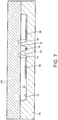
- Fig. 6 to Fig. 8 are cross-sectional views schematically illustrating the manufacturing process of the physical quantity sensor 100 according to the present embodiment.
- a substrate 10 provided with a recessed portion 11, a post portion 13 having a hollow 15, and groove portions 17, 18, and 19 is prepared, by patterning, for example, a glass substrate (step S1).
- the patterning is performed by, for example, photolithography and etching.
- step S2 fixed electrodes 50 and 52 are formed on the bottom surface 12 of the recessed portion 11 (step S2).
- wirings 70 and 72 and a wiring layer portion 74a are formed on the substrate 10 (see Fig. 1 and Fig. 4 ).
- a bump portion 74b is formed on the wiring layer portion 74a (see Fig. 4 ).
- the third wiring 74 can be formed.
- the top surface of the bump portion 74b is formed so as to be positioned higher than the top surface 14 of the post portion 13.
- pads 80, 82, and 84 are formed so as to be connected with the wirings 70, 72, and 74, respectively (see Fig. 1 ).
- the wirings 70 and 72 and the wiring layer portion 74a may be formed by the same process as that of the fixed electrodes 50 and 52.
- the fixed electrodes 50 and 52, the wirings 70, 72, and 74, and the pads 80, 82, and 84 are formed by film formation and patterning by, for example, a sputtering method or a chemical vapor deposition (CVD) method.
- the patterning is performed by, for example, photolithography and etching.
- a silicon substrate 102 is bonded to the substrate 10 (step S3).
- the bonding of the substrate 10 and the silicon substrate 102 is performed, for example, by anodic bonding. Thereby, the substrate 10 and the silicon substrate 102 can be firmly bonded.
- the silicon substrate 102 is depressed by being pushed by the bump portion 74b of the third wiring 74 (see Fig. 4 ).
- the silicon substrate 102 can be firmly connected to the bump portion 74b.
- the silicon substrate 102 is ground by, for example, a grinding machine to form a thin film, then, the thin film is patterned into a predetermined shape, and the movable body 20 and the support portion 30 are integrally formed (step S4).
- Patterning is performed by photolithography and etching (dry etching), and the Bosch method by an inductive coupling method can be used as a more specific etching technique.
- the lid body 90 is bonded to the substrate 10, and the movable body 20 and the like are accommodated in the cavity 92 formed by the substrate 10 and the lid body 90 (step S5).
- the bonding of the substrate 10 and the lid body 90 is performed, for example, by anodic bonding. Thereby, the substrate 10 and the lid body 90 can be firmly bonded to each other. By performing this process in an inert gas atmosphere, it is possible to fill the cavity 92 with an inert gas.
- the physical quantity sensor 100 can be manufactured.
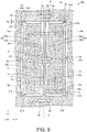
- Fig. 9 is a plan view schematically illustrating a physical quantity sensor 200 according to the first modification example of the present embodiment.
- illustration of the lid body 90 is omitted in Fig. 9 .
- the X axis, the Y axis, and the Z axis are illustrated as three axes orthogonal to each other.
- the physical quantity sensor 200 differs from the physical quantity sensor 100 described above in that the support portion 30 includes a first stopper 210, a second stopper 212, a third stopper 214, and a fourth stopper 216, as illustrated in Fig. 9 .
- the planar shapes of the stoppers 210, 212, 214, and 216 are rectangles.
- the first stopper 210 protrudes from the first fixed portion 32 to the side opposite to the third beam portion 43 side in the X-axis direction. Specifically, the first stopper 210 protrudes from the first fixed portion 32 to the -X-axis direction side. In the illustrated example, the first stopper 210 is provided in the end portion on the +Y axis direction side, the end portion on the -Y axis direction side, and the center portion of the first fixed portion 32.
- the shortest distance D5 in the X-axis direction between the first stopper 210 and the movable body 20 is shorter than the shortest distance D3 in the X-axis direction between the second fixed portion 34 and the third beam portion 43.
- the distance D5 may be shorter than a shortest distance in the X-axis direction between the second fixed portion 34 and the fourth beam portion 44.
- the second stopper 212 protrudes from the first fixed portion 32 in the Y-axis direction.
- the second stopper 212 is provided at the end portion on the +Y-axis direction side and the end portion on the -Y-axis direction side of the first fixed portion 32.
- the second stopper 212 is provided integrally with the first stopper 210. Thus, the number of parts can be reduced.
- the shortest distance D6 in the Y-axis direction between the second stopper 212 and the movable body 20 is shorter than the shortest distance D1 in the X-axis direction between the first fixed portion 32 and the third beam portion 43.
- the distance D6 may be shorter than a shortest distance in the X-axis direction between the first fixed portion 32 and the fourth beam portion 44.
- the third stopper 214 protrudes from the second fixed portion 34 in the X-axis direction.
- the third stopper 214 is provided at the end portion on the +Y-axis direction side, the end portion on the -Y-axis direction side, and the center part of the second fixed portion 34.
- the shortest distance in the X-axis direction between the third stopper 214 and the movable body 20 is shorter than the shortest distance D1 in the X-axis direction between the first fixed portion 32 and the third beam portion 43.
- the shortest distance in the X-axis direction between the third stopper 214 and the movable body 20 is shorter than the shortest distance in the X-axis direction between the first fixed portion 32 and the fourth beam portion 44.
- the fourth stopper 216 protrudes from the second fixed portion 34 in the Y-axis direction.
- the fourth stopper 216 is provided at the end portion on the +Y-axis direction side and the end portion on the -Y-axis direction side of the second fixed portion 34.
- the fourth stopper 216 is provided integrally with the third stopper 214. Thus, the number of parts can be reduced.
- the shortest distance in the Y-axis direction between the fourth stopper 216 and the movable body 20 is shorter than the shortest distance D3 in the X-axis direction between the second fixed portion 34 and the third beam portion 43.
- the shortest distance in the Y-axis direction between the fourth stopper 216 and the movable body 20 is shorter than the shortest distance in the X-axis direction between the second fixed portion 34 and the fourth beam portion 44.
- the physical quantity sensor 200 can have the same effect as the physical quantity sensor 100 described above.
- the support portion 30 includes a first stopper 210 protruding from the first fixed portion 32 to the -X-axis direction side, and the shortest distance D5 in the X-axis direction between the first stopper 210 and the movable body 20 is shorter than the shortest distance D3 in the X-axis direction between the second fixed portion 34 and the third beam portion 43. Therefore, in the physical quantity sensor 200, even if a strong impact is applied and the movable body 20 and the third beam portion 43 are displaced to the +X axis direction side, before the third beam portion 43 collides with the second fixed portion 34, the movable body 20 collides with the first stopper 210. Therefore, in the physical quantity sensor 200, the possibility of breakage of the third beam portion 43 can be reduced.
- the distance D5 is shorter than a shortest distance in the X-axis direction between the second fixed portion 34 and the fourth beam portion 44. Therefore, in the physical quantity sensor 200, the possibility of breakage of the fourth beam portion 44 can be reduced.
- the support portion 30 includes a second stopper 212 protruding from the first fixed portion 32 to the Y-axis direction side, and the shortest distance D6 in the Y-axis direction between the second stopper 212 and the movable body 20 is shorter than the shortest distance D1 in the X-axis direction between the first fixed portion 32 and the third beam portion 43. Therefore, in the physical quantity sensor 200, even if a strong impact is applied and the movable body 20 and the third beam portion 43 rotate counterclockwise about the Z axis, before the third beam portion 43 collides with the first fixed portion 32, the movable body 20 collides with the second stopper 212. Therefore, in the physical quantity sensor 200, the possibility of breakage of the third beam portion 43 can be reduced.
- the distance D6 is shorter than a shortest distance in the X-axis direction between the first fixed portion 32 and the fourth beam portion 44. Therefore, in the physical quantity sensor 200, even if a strong impact is applied and the movable body 20 and the fourth beam portion 44 rotate clockwise about the Z axis, before the fourth beam portion 44 collides with the first fixed portion 32, the movable body 20 collides with the second stopper 212. Therefore, in the physical quantity sensor 200, the possibility of breakage of the fourth beam portion 44 can be reduced.
- the support portion 30 includes a third stopper 214 protruding from the second fixed portion 34 to the +X-axis direction side, and the shortest distance in the X-axis direction between the third stopper 214 and the movable body 20 is shorter than the shortest distance D1 in the X-axis direction between the first fixed portion 32 and the third beam portion 43. Therefore, in the physical quantity sensor 200, even if a strong impact is applied and the movable body 20 and the third beam portion 43 are displaced to the -X axis direction side, before the third beam portion 43 collides with the first fixed portion 32, the movable body 20 collides with the third stopper 214. Therefore, in the physical quantity sensor 200, the possibility of breakage of the third beam portion 43 can be reduced.
- the shortest distance in the X-axis direction between the third stopper 214 and the movable body 20 is shorter than the shortest distance in the X-axis direction between the first fixed portion 32 and the fourth beam portion 44. Therefore, in the physical quantity sensor 200, the possibility of breakage of the fourth beam portion 44 can be reduced.
- the support portion 30 includes a fourth stopper 216 protruding from the second fixed portion 34 toward the Y-axis direction, and the shortest distance in the Y-axis direction between the fourth stopper 216 and the movable body 20 is shorter than the shortest distance D3 in the X-axis direction between the second fixed portion 34 and the third beam portion 43. Therefore, in the physical quantity sensor 200, even if a strong impact is applied and the movable body 20 and the third beam portion 43 rotate clockwise about the Z axis, before the third beam portion 43 collides with the second fixed portion 34, the movable body 20 collides with the fourth stopper 216. Therefore, in the physical quantity sensor 200, the possibility of breakage of the third beam portion 43 can be reduced.
- the shortest distance in the Y-axis direction between the fourth stopper 216 and the movable body 20 is shorter than the shortest distance in the X-axis direction between the second fixed portion 34 and the fourth beam portion 44. Therefore, in the physical quantity sensor 200, even if a strong impact is applied and the movable body 20 and the fourth beam portion 44 rotate counterclockwise about the Z axis, before the fourth beam portion 44 collides with the second fixed portion 34, the movable body 20 collides with the fourth stopper 216. Therefore, in the physical quantity sensor 200, the possibility of breakage of the fourth beam portion 44 can be reduced.
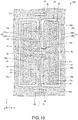
- Fig. 10 is a plan view schematically illustrating a physical quantity sensor 300 according to the second modification example of the present embodiment.
- illustration of the lid body 90 is omitted in Fig. 10 .
- the X axis, the Y axis, and the Z axis are illustrated as three axes orthogonal to each other.
- the planar shape of the third beam portion 43 is a rectangle.
- the third beam portion 43 includes width changing portions 43a and 43b whose width gradually changes in plan view.
- the width of the width changing portion 43a decreases toward the +Y-axis direction.
- the width changing portion 43a is connected to the first beam portion 41.
- the width of the width changing portion 43b decreases toward the -Y-axis direction.
- the width changing portion 43b is connected to the fifth beam portion 45.
- the beam portions 41 and 43 do not form a pointed corner.
- the beam portions 43 and 45 do not form a pointed corner. That is, the root of the third beam portion 43 does not form a pointed corner.
- the fourth beam portion 44 includes width changing portions 44a and 44b whose width gradually changes in plan view.
- the width of the width changing portion 44a decreases toward the -Y-axis direction.
- the width changing portion 44a is connected to the second beam portion 42.
- the width of the width changing portion 44b decreases toward the +Y-axis direction.
- the width changing portion 44b is connected to the sixth beam portion 46.
- the beam portions 42 and 44 do not form a pointed corner.
- the beam portions 44 and 46 do not form a pointed corner. That is, the root of the fourth beam portion 44 does not form a pointed corner.
- the roots of the beam portions 41, 42, 45 and 46 do not form a pointed corner.
- the physical quantity sensor 300 can have the same effect as the physical quantity sensor 100 described above.
- the width of the third beam portion 43 decreases toward the +Y-axis direction
- the third beam portion 43 includes a width changing portion 43a connected to the first beam portion 41, and a width changing portion 43b of which width decreases toward the -Y axis direction and which is connected to the fifth beam portion 45. That is, the root of the third beam portion 43 does not form a pointed corner. Therefore, in the physical quantity sensor 300, it is possible to suppress concentration of stress on the root of the third beam portion 43. Similarly, in the physical quantity sensor 300, it is possible to suppress concentration of stress on the roots of the beam portions 41, 42, 44, 45 and 46.
- the support portion 30 may include the stoppers 210, 212, 214, and 216, as in the physical quantity sensor 200 illustrated in Fig. 9 .
- Fig. 11 is a functional block diagram of the electronic device 1000 according to the present embodiment.
- the electronic device 1000 includes the physical quantity sensor according to the invention.
- the physical quantity sensor 100 is included as a physical quantity sensor according to the invention will be described.
- the electronic device 1000 is configured to further include an arithmetic processing unit (CPU) 1020, an operation unit 1030, a read only memory (ROM) 1040, a random access memory (RAM) 1050, a communication unit 1060, and a display unit 1070. It is to be noted that the electronic device according to the present embodiment may be configured in such a manner that a part of the constituent elements (respective portions) in Fig. 11 is omitted or changed, or other constituent elements are added.
- CPU arithmetic processing unit
- ROM read only memory
- RAM random access memory
- the arithmetic processing unit 1020 performs various calculation processes and control processes according to a program stored in the ROM 1040 or the like. Specifically, the arithmetic processing unit 1020 performs various processes according to the output signal of the physical quantity sensor 100, or the operation signal from the operation unit 1030, a process of controlling the communication unit 1060 for data communication with an external device, a process of transmitting a display signal for displaying various types of information on the display unit 1070, and the like.
- the operation unit 1030 is an input device including an operation key, a button switch, and the like, and outputs an operation signal corresponding to an operation by a user to the arithmetic processing unit 1020.
- the ROM 1040 stores programs, data, and the like for the arithmetic processing unit 1020 to perform various calculation processes and control processes.
- the RAM 1050 is used as a work area of the arithmetic processing unit 1020 and temporarily stores programs and data read from the ROM 1040, data input from the physical quantity sensor 100, data input from the operation unit 1030, a calculation result obtained by the arithmetic processing unit 1020 executing various programs according to the instruction, and the like.
- the communication unit 1060 performs various controls for establishing data communication between the arithmetic processing unit 1020 and the external device.
- the display unit 1070 is a display device composed of a liquid crystal display (LCD) or the like, and displays various types of information based on a display signal input from the arithmetic processing unit 1020.
- a touch panel functioning as the operation unit 1030 may be provided in the display unit 1070.
- a personal computer for example, a mobile type personal computer, a laptop type personal computer, a tablet type personal computer
- a mobile terminal such as a smart phone and a mobile phone
- a digital still camera for example, an inkjet type discharge device (for example, an ink jet printer)
- a storage area network device such as a router and a switch, a local area network device, a mobile terminal base station device, a television, a video camera, a video recorder, a car navigation device, a real time clock device, a pager, an electronic diary (with a communication function), an electronic dictionary, a calculator, an electronic game machine, a game controller, a word processor, a work station, a videophone, a security TV monitor, electronic binoculars, a POS terminal, medical equipment (for example, an electronic clinical thermometer, a blood pressure monitor, a blood glucose meter, an electrocardiogram measuring device, an ultrasonic diagnostic device, an electronic endoscope
- medical equipment for example, an electronic clinical thermometer
- Fig. 12 is a view illustrating an example of an external appearance of a smartphone which is an example of the electronic device 1000.
- a smartphone which is the electronic device 1000 includes a button as an operation unit 1030 and an LCD as the display unit 1070.
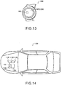
- Fig. 13 is a diagram illustrating an example of an appearance of a wrist-worn portable device (wearable device) which is an example of the electronic device 1000.
- the wearable device which is the electronic device 1000 includes an LCD as the display unit 1070.
- a touch panel functioning as the operation unit 1030 may be provided in the display unit 1070.
- the portable device which is the electronic device 1000, includes a position sensor such as a Global Positioning System (GPS) receiver, for example, and can measure a moving distance and a moving trajectory of the user.
- GPS Global Positioning System
- Fig. 14 is a perspective view schematically illustrating a car, as the vehicle 1100 according to the present embodiment.
- the vehicle according to the present embodiment includes the physical quantity sensor according to the invention.
- a vehicle including the physical quantity sensor 100 will be described as a physical quantity sensor according to the invention.
- the vehicle 1100 according to the present embodiment is configured to further include a controller 1120 that controls an engine system, a brake system, a keyless entry system, and the like, a controller 1130, a controller 1140, a battery 1150, and a backup battery 1160. Note that, in the vehicle 1100 according to the present embodiment, a part of the constituent elements (each unit) illustrated in Fig. 14 may be omitted or changed, or other constituent elements may be added.
- vehicle 1100 various vehicles are conceivable, examples of which include an automobile (including an electric car), an aircraft such as a jet aircraft and a helicopter, a ship, a rocket, an artificial satellite, and the like.
- the invention includes substantially the same configuration (for example, a configuration having the same function, method, and result, or a configuration having the same purpose and effect) as the configuration described in the embodiment. Further, the invention includes configurations in which the non-essential parts of the configuration described in the embodiment are replaced. Further, the invention includes configurations that achieve the same effect as the configuration described in the embodiment or configurations that can achieve the same object. Further, the invention includes configurations in which a well-known technology is added to the configuration described in the embodiment.
Landscapes
- Physics & Mathematics (AREA)
- General Physics & Mathematics (AREA)
- Chemical & Material Sciences (AREA)
- Analytical Chemistry (AREA)
- Engineering & Computer Science (AREA)
- Computer Hardware Design (AREA)
- Microelectronics & Electronic Packaging (AREA)
- Pressure Sensors (AREA)
- Micromachines (AREA)
Abstract
Description
- The present invention relates to a physical quantity sensor, an electronic device, and a vehicle.
- In recent years, a physical quantity sensor measuring a physical quantity such as an acceleration has been developed using, for example, a silicon micro electro mechanical systems (MEMS) technique.
- For example,
JP-A-2012-181030 - However, in an acceleration sensor described in
JP-A-2012-181030 - An advantage of some aspects of the invention is to provide a physical quantity sensor in which a possibility of breakage of a beam portion can be reduced.
- Another advantage of some aspects of the invention is to provide an electronic device including the physical quantity sensor.
- Another advantage of some aspects of the invention is to provide a vehicle including the physical quantity sensor.
- The invention can be implemented as the following forms or application examples.
- A physical quantity sensor according to this application example includes a substrate; a movable body that is displaceable about a support axis according to a physical quantity and is provided with an opening portion; and a support portion that is provided on the substrate and is located in the opening portion, the support portion includes a first fixed portion and a second fixed portion that are fixed to the substrate and provided so as to sandwich the support axis in plan view; a first beam portion and a second beam portion that each connect the first fixed portion with the second fixed portion and are provided apart from each other; a third beam portion extending in a direction of the support axis and connecting the first beam portion with the movable body; and a fourth beam portion extending in a direction of the support axis and connecting the second beam portion with the movable body.
- In such a physical quantity sensor, in a case where a strong impact is applied in the Z-axis direction, the first beam portion and the second beam portion can be torsionally deformed. Thus, in the physical quantity sensor, in a case where a strong impact is applied in the Z-axis direction, it is possible to suppress stress concentration on the end portion on the first beam portion side of the third beam portion and the end portion on the second beam portion side of the fourth beam portion.
- Therefore, in such a physical quantity sensor, the possibility of breakage of the third beam portion and the fourth beam portion can be reduced.
- In the physical quantity sensor according to the application example, a shortest distance in a direction intersecting the direction of the support axis between the first fixed portion and the third beam portion may be shorter than a shortest distance in the intersecting direction between the first fixed portion and a connecting portion of the first beam portion to the third beam portion, and a shortest distance in the intersecting direction between the second fixed portion and the third beam portion may be shorter than a shortest distance between the second fixed portion and the connecting portion.
- In such a physical quantity sensor, in the case of forming the movable body and the support portion by etching using inductive coupling method (ICP), the etching rate of the portion to form the third beam portion can be reduced.
- Thus, the third beam portion can be formed with high accuracy.
- In the physical quantity sensor according to the application example, the first beam portion and the second beam portion may be displaceable about an axis intersecting the support axis.
- In such a physical quantity sensor, in a case where a strong impact is applied in the Z-axis direction, the first beam portion and the second beam portion can be torsionally deformed about the axis intersecting the support axis.
- In the physical quantity sensor according to the application example, the movable body may include a fifth beam portion and a sixth beam portion extending a direction intersecting a direction of the support axis, the third beam portion may connect the first beam portion with the fifth beam portion, and the fourth beam portion may connect the second beam portion with the sixth beam portion.
- In such a physical quantity sensor, in a case where a strong impact is applied in the Z-axis direction, the fifth beam portion and the sixth beam portion can be torsionally deformed. Thus, in such a physical quantity sensor, in a case where a strong impact is applied in the Z-axis direction, it is possible to reduce stress concentration on the end portion on the fifth beam portion side of the third beam portion and the end portion on the sixth beam portion side of the fourth beam portion.
- In the physical quantity sensor according to the application example, the fifth beam portion and the sixth beam portion may be displaceable about an axis intersecting the support axis.
- In such a physical quantity sensor, in a case where a strong impact is applied in the Z-axis direction, the fifth beam portion and the sixth beam portion can be torsionally deformed about the axis intersecting the support axis.
- In the physical quantity sensor according to the application example, the support portion may include a first stopper protruding from the first fixed portion toward a side opposite to the third beam portion side in a direction intersecting the direction of the support axis, a shortest distance in the intersecting direction between the first stopper and the movable body may be shorter than a shortest distance in the intersecting direction between the second fixed portion and the third beam portion.
- In such a physical quantity sensor, even if a strong impact is applied and the movable body and the third beam portion are displaced to the X-axis direction (in a direction intersecting the direction of the support axis), before the third beam portion collides with the second fixed portion, the movable body collides with the first stopper.
- Therefore, in such a physical quantity sensor, the possibility of breakage of the third beam portion can be reduced.
- In the physical quantity sensor according to the application example, the support portion may include a second stopper protruding from the first fixed portion toward the direction of the support axis, and a shortest distance in the direction of the support axis between the second stopper and the movable body may be shorter than a shortest distance in a direction intersecting the direction of the support axis between the first fixed portion and the third beam portion.
- In such a physical quantity sensor, even if a strong impact is applied and the movable body and the third beam portion rotate counterclockwise about the Z axis, before the third beam portion collides with the first fixed portion, the movable body collides with the second stopper.
- Therefore, in such a physical quantity sensor, the possibility of breakage of the third beam portion can be reduced.
- An electronic device according to this application example includes the physical quantity sensor according to the application example, an arithmetic processing unit that performs an arithmetic process based on an output signal from the physical quantity sensor, and a display unit that displays information according to control of the arithmetic processing unit.
- Such an electronic device can include the physical quantity sensor according to the application example.
- A portable electronic device according to an application example includes the physical quantity sensor according to the application example, an arithmetic processing unit that performs an arithmetic process based on an output signal from the physical quantity sensor, a communication unit that performs data communication with an outside, an operation unit that transmits an operation signal to the arithmetic processing unit; and a display unit that displays information according to control of the arithmetic processing unit.
- A portable electronic device according to an application example includes a GPS receiver, and measures a movement distance and a movement trajectory of a user.
- A vehicle according to this application example includes the physical quantity sensor according to the application example.
- A vehicle according to an application example includes at least one system of an engine system, a brake system, and a keyless entry system, and a controller that controls the system, based on an output signal from the physical quantity sensor.
- Such a vehicle can include the physical quantity sensor according to the application example.
- The invention will be described with reference to the accompanying drawings, wherein like numbers reference like elements.
-
Fig. 1 is a plan view schematically illustrating a physical quantity sensor according to a present embodiment. -
Fig. 2 is a plan view schematically illustrating the physical quantity sensor according to the present embodiment. -
Fig. 3 is a cross-sectional view schematically illustrating the physical quantity sensor according to the present embodiment. -
Fig. 4 is a cross-sectional view schematically illustrating the physical quantity sensor according to the present embodiment. -
Fig. 5 is a flowchart for explaining a physical quantity sensor manufacturing method according to the present embodiment. -
Fig. 6 is a cross-sectional view schematically illustrating the manufacturing process of the physical quantity sensor according to the present embodiment. -
Fig. 7 is a cross-sectional view schematically illustrating the manufacturing process of the physical quantity sensor according to the present embodiment. -
Fig. 8 is a cross-sectional view schematically illustrating the manufacturing process of the physical quantity sensor according to the present embodiment. -
Fig. 9 is a plan view schematically illustrating the physical quantity sensor according to a first modification example of the present embodiment. -
Fig. 10 is a plan view schematically illustrating the physical quantity sensor according to a second modification example of the present embodiment. -
Fig. 11 is a functional block diagram of an electronic device according to the present embodiment. -
Fig. 12 is a view schematically illustrating an appearance of a smartphone which is an example of the electronic device according to the present embodiment. -
Fig. 13 is a view schematically illustrating an appearance of a wearable device which is an example of the electronic device according to the present embodiment. -
Fig. 14 is a plan view schematically illustrating a vehicle according to the present embodiment. - Hereinafter, preferred embodiments of the invention will be described in detail with reference to the drawings. In addition, the embodiments to be described below do not unfairly limit the contents of the invention described in the appended claims. Further, not all of the configurations to be described below are necessarily essential constituent elements of the invention.
- First, a physical quantity sensor according to a present embodiment will be described with reference to the drawings.
Fig. 1 is a plan view schematically illustrating aphysical quantity sensor 100 according to the present embodiment.Fig. 2 is an enlarged view of the periphery of asupport portion 30 of thephysical quantity sensor 100 according to the present embodiment.Fig. 3 is a cross-sectional view taken along a line III-III ofFig. 1 schematically illustrating thephysical quantity sensor 100 according to the present embodiment.Fig. 4 is a cross-sectional view taken along a line IV-IV inFig. 1 schematically illustrating thephysical quantity sensor 100 according to the present embodiment. InFig. 1 to Fig. 4 , an X axis, a Y axis, and a Z axis are illustrated as three axes orthogonal to each other. - As illustrated in
Fig. 1 to Fig. 4 , thephysical quantity sensor 100 includes asubstrate 10, amovable body 20, asupport portion 30, a first fixedelectrode 50, a second fixedelectrode 52, afirst wiring 70, asecond wiring 72, athird wiring 74, afirst pad 80, asecond pad 82, athird pad 84, and alid body 90. For the sake of convenience,Fig. 1 shows thelid body 90 in perspective. InFigs. 2 to 4 , the illustration of thelid body 90 is omitted. - In the following, an example will be described in which the
physical quantity sensor 100 is an acceleration sensor (a capacitive MEMS acceleration sensor) that measures an acceleration in the vertical direction (Z-axis direction). - The material of the
substrate 10 is, for example, an insulating material such as glass. For example, since thesubstrate 10 is made of an insulating material such as glass and themovable body 20 is made of a semiconductor material such as silicon, it is possible to electrically insulate them from each other easily, and simplify the sensor structure. - On the
substrate 10, a recessedportion 11 is formed. Themovable body 20 is provided above the recessedportion 11 through gaps. In the example illustrated inFig. 1 , the planar shape (the shape seen from the Z-axis direction) of the recessedportion 11 is a rectangle. - The
substrate 10 includes a projection post portion (projection portion) 13 on the bottom surface (the surface of thesubstrate 10 defining the recessed portion 11) 12 of the recessedportion 11. Thepost portion 13 is a projection portion protruding upward (+ Z-axis direction) than thebottom surface 12. As illustrated inFig. 3 , the height of the post portion 13 (the distance between thetop surface 14 and thebottom surface 12 of the post portion 13) and the depth of the recessedportion 11 are equal, for example. Thetop surface 14 of thepost portion 13 is bonded to thesupport portion 30. A hollow 15 is formed on thetop surface 14 of thepost portion 13, as illustrated inFig. 4 . Athird wiring 74 is provided on thebottom surface 16 of the hollow 15 (the surface of thepost portion 13 defining the hollow 15). - In the example illustrated in
Fig. 3 andFig. 4 , the side surface of the recessed portion 11 (the side surface of thesubstrate 10 defining the recessed portion 11) and the side surface of thepost portion 13 are inclined with respect to thebottom surface 12 of the recessedportion 11, but may be perpendicular to thebottom surface 12. - As illustrated in
Fig. 1 , thesubstrate 10 is provided withgroove portions - The
movable body 20 is displaced in a direction (for example, a Z-axis direction) intersecting with the main surface of thesubstrate 10 according to a physical quantity (for example, an acceleration). Themovable body 20 is displaceable about the support axis Q according to the physical quantity. Specifically, when an acceleration in the vertical direction (Z-axis direction) is applied, themovable body 20 swings like a seesaw with the support axis Q determined by thebeam portions support portion 30 as the rotation axis (rocking axis). The support axis Q is, for example, parallel to the Y axis. In the example illustrated inFig. 1 , the planar shape of themovable body 20 is a rectangle. The thickness (size in the Z-axis direction) of themovable body 20 is, for example, constant. - The
movable body 20 includes a first seesaw piece (first movable portion) 20a and a second seesaw piece (first movable portion) 20b. - The
movable body 20 includes the first seesaw piece (first movable portion) 20a on one side in a direction orthogonal to the rotation axis, with the rotation axis as a boundary, the second seesaw piece (first movable portion) 20b on the other side of the orthogonal direction, afifth beam portion 45 and asixth beam portion 46 connecting the first seesaw piece (first movable portion) 20a with the second seesaw piece (first movable portion) 20b, an openingportion 26 is disposed, in plan view, between thefifth beam portion 45 and thesixth beam portion 46, athird beam portion 43 connects afirst beam portion 41 and thefifth beam portion 45, and afourth beam portion 44 connects asecond beam portion 42 with thesixth beam portion 46. Thefirst seesaw piece 20a is positioned on one side (on the -X-axis direction side in the illustrated example) of the support axis Q in plan view (viewed from the Z-axis direction). In plan view, thesecond seesaw piece 20b is positioned on the other side (on the +X-axis direction side in the illustrated example) of the support axis Q. - When acceleration (for example, gravitational acceleration) in the vertical direction is applied to the
movable body 20, a rotational moment (moment of force) is generated in each of thefirst seesaw piece 20a and thesecond seesaw piece 20b. Here, in a case where the rotational moment of thefirst seesaw piece 20a (for example, the counterclockwise rotational moment) and the rotational moment of thesecond seesaw piece 20b (for example, the clockwise rotational moment) are balanced, the inclination of themovable body 20 does not change and the acceleration cannot be measured. Therefore, themovable body 20 is designed so that when the acceleration in the vertical direction is applied, the rotational moment of thefirst seesaw piece 20a and the rotational moment of thesecond seesaw piece 20b are not balanced, and a predetermined inclination occurs in themovable body 20. - In the
physical quantity sensor 100, by disposing the support axis Q at a position deviated from the center (the center of gravity) of the movable body 20 (by making the distances from the support axis Q to the distal ends of theseesaw pieces seesaw pieces movable body 20 has different masses on one side (first seesaw piece 20a) and the other side (second seesaw piece 20b), with the support axis Q as a boundary. In the illustrated example, the distance from the support axis Q to theend surface 23 of thefirst seesaw piece 20a is greater than the distance from the support axis Q to theend surface 24 of thesecond seesaw piece 20b. Further, the thickness of thefirst seesaw piece 20a is equal to the thickness of thesecond seesaw piece 20b. Therefore, the mass of thefirst seesaw piece 20a is larger than the mass of thesecond seesaw piece 20b. - In this way, since the
seesaw pieces first seesaw piece 20a and the rotational moment of thesecond seesaw piece 20b can be made not balanced when the acceleration in the vertical direction is applied. Therefore, when the acceleration in the vertical direction is applied, a predetermined inclination can be generated in themovable body 20. - Although not shown, the support axis Q is disposed at the center of the
movable body 20 and theseesaw pieces seesaw pieces movable body 20. - The
movable body 20 is provided apart from thesubstrate 10. Themovable body 20 is provided above the recessedportion 11. A gap is provided between themovable body 20 and thesubstrate 10. Thus, themovable body 20 can swing like a seesaw. - The
movable body 20 includes a firstmovable electrode 21 and a secondmovable electrode 22 provided, having a support axis Q as a boundary. The firstmovable electrode 21 is provided in thefirst seesaw piece 20a. The secondmovable electrode 22 is provided in thesecond seesaw piece 20b. - The first
movable electrode 21 is a section overlapping the first fixedelectrode 50 of themovable body 20, in plan view. The firstmovable electrode 21 and the first fixedelectrode 50 form a capacitance C1. That is, the capacitance C1 is formed by the firstmovable electrode 21 and the first fixedelectrode 50. - The second
movable electrode 22 is a section overlapping the second fixedelectrode 52 of themovable body 20, in plan view. The secondmovable electrode 22 and the second fixedelectrode 52 form a capacitance C2. That is, the capacitance C2 is formed by the secondmovable electrode 22 and the second fixedelectrode 52. In thephysical quantity sensor 100, themovable body 20 is made of a conductive material (impurity-doped silicon), so that themovable electrodes first seesaw piece 20a functions as the firstmovable electrode 21, and thesecond seesaw piece 20b functions as the secondmovable electrode 22. - The capacitance C1 and the capacitance C2 are configured so as to be equal to each other, for example, when the
movable body 20 illustrated inFig. 3 is in a horizontal state. The positions of themovable electrodes movable body 20. The capacitances C1 and C2 change depending on the positions of themovable electrodes movable body 20 through thesupport portion 30. - In the
movable body 20, a throughhole 25 penetrating themovable body 20 is formed. Thus, it is possible to reduce the influence of air (resistance of air) when themovable body 20 swings. A plurality of the throughholes 25 are formed. In the illustrated example, the planar shape of the throughhole 25 is a square. - In the
movable body 20, an openingportion 26 penetrating themovable body 20 is formed. The openingportion 26 is provided on the support axis Q in plan view. In the illustrated example, the planar shape of the openingportion 26 is rectangular. - The
support portion 30 is provided on thesubstrate 10. Thesupport portion 30 is positioned in the openingportion 26. Thesupport portion 30 supports themovable body 20. As illustrated inFig. 2 , thesupport portion 30 includes a first fixedportion 32, a second fixedportion 34, thefirst beam portion 41, thesecond beam portion 42, thethird beam portion 43, and thefourth beam portion 44. - The first fixed
portion 32 and the second fixedportion 34 are fixed to thesubstrate 10. The fixedportions portion 32 is provided on the -X-axis direction side of the support axis Q, and the second fixedportion 34 is provided on the +X-axis direction side of the support axis Q. The fixedportions top surface 14 of thepost portion 13, as illustrated inFig. 3 . - As illustrated in
Fig. 2 , the first fixedportion 32 includes, for example, abase portion 32a having a rectangular shape in plan view and a protrudingportion 32b protruding from thebase portion 32a toward the +X-axis direction side. In the illustrated example, two protrudingportions 32b are provided. The second fixedportion 34 includes, for example, abase portion 34a having a rectangular shape in plan view and a protrudingportion 34b protruding from thebase portion 34a toward the -X-axis direction side. In the illustrated example, two protrudingportions 34b are provided. - The
first beam portion 41 and thesecond beam portion 42 are provided apart from thesubstrate 10. Thebeam portions portion 32 and the second fixedportion 34. In the illustrated example, thebeam portions base portion 32a with thebase portion 34a. Thebeam portions portion 32 to the second fixedportion 34, in a direction (for example, an orthogonal direction, in the illustrated example, the X-axis direction) intersecting the direction of the support axis Q (the extending direction of the support axis Q, in the illustrated example, the Y-axis direction). Thebeam portions beam portions beam portions support portion 30, an openingportion 36 defined by the fixedportions beam portions - The
third beam portion 43 is provided apart from thesubstrate 10. Thethird beam portion 43 connects thefirst beam portion 41 with themovable body 20. Thethird beam portion 43 extends from thefirst beam portion 41 to themovable body 20 in the Y-axis direction. Thethird beam portion 43 is provided on the support axis Q. Thethird beam portion 43 has a planar shape whose longitudinal direction is the Y-axis direction. The planar shape of thethird beam portion 43 is, for example, a rectangle. - The
fourth beam portion 44 is provided apart from thesubstrate 10. Thefourth beam portion 44 connects thesecond beam portion 42 with themovable body 20. Thefourth beam portion 44 extends from thesecond beam portion 42 to themovable body 20 in the Y-axis direction. Thefourth beam portion 44 is provided on the support axis Q. Thefourth beam portion 44 has a planar shape whose longitudinal direction is the Y-axis direction. The planar shape of thefourth beam portion 44 is, for example, a rectangle. - In the illustrated example, the
movable body 20 includes afifth beam portion 45 and asixth beam portion 46. Thebeam portions beam portions beam portions fifth beam portion 45 is provided on the +Y-axis direction side of thesupport portion 30. In themovable body 20, an openingportion 27 defined by thefifth beam portion 45 is formed. Thesixth beam portion 46 is provided on the -Y-axis direction side of thesupport portion 30. In themovable body 20, an openingportion 28 defined by thesixth beam portion 46 is formed. Thethird beam portion 43 connects thefirst beam portion 41 with thefifth beam portion 45. Thefourth beam portion 44 connects thesecond beam portion 42 with thesixth beam portion 46. - The
first beam portion 41 is displaceable about an axis R1 intersecting (orthogonal in the illustrated example) the support axis Q. Thesecond beam portion 42 is displaceable about an axis R2 orthogonal to the support axis Q. Thefifth beam portion 45 is displaceable about an axis R3 orthogonal to the support axis Q. Thesixth beam portion 46 is displaceable about an axis R4 orthogonal to the support axis Q. Thebeam portions - The
third beam portion 43 and thefourth beam portion 44 are displaceable about the support axis Q. Thebeam portions beam portions movable body 20 swings like a seesaw. - In the illustrated example, the shortest distance D1 in the X-axis direction between the first fixed
portion 32 and thethird beam portion 43 is shorter than the shortest distance D2 in the X-axis direction between the first fixedportion 32 and a first connectingportion 41a of thefirst beam portion 41 to thethird beam portion 43. Further, the shortest distance D3 in the X-axis direction between the second fixedportion 34 and thethird beam portion 43 is shorter than the shortest distance D4 in the X-axis direction between the second fixedportion 34 and the first connectingportion 41a. - Similarly, the shortest distance in the X-axis direction between the first fixed
portion 32 and thefourth beam portion 44 may be shorter than the shortest distance in the X-axis direction between the first fixedportion 32 and a second connectingportion 42a of thesecond beam portion 42 to thefourth beam portion 44. Further, the shortest distance in the X-axis direction between the second fixedportion 34 and thefourth beam portion 44 is shorter than the shortest distance in the X-axis direction between the second fixedportion 34 and the second connectingportion 42a. - The lengths (sizes in the Y-axis direction) of the
third beam portion 43 and thefourth beam portion 44 is shorter than, for example, the lengths (sizes in the X-axis direction) of thefirst beam portion 41, thesecond beam portion 42, thefifth beam portion 45, and thesixth beam portion 46. The widths (sizes in the X-axis direction) of thebeam portions beam portions third beam portion 43 and thefourth beam portion 44 may be the same as the distance between thethird beam portion 43 and the fourth beam portion 44 (size in the Y-axis direction of the opening portion 36). The distance D1 may be shorter than a shortest distance in the Y-axis direction between the protrudingportion 32b and thefirst beam portion 41. - The
movable body 20 and thesupport portion 30 are integrally provided. The material of themovable body 20 and thesupport portion 30 is, for example, silicon to which conductivity is imparted by doping impurities such as phosphorus and boron. In a case where the material of thesubstrate 10 is glass and the materials of themovable body 20 and thesupport portion 30 are silicon, thesubstrate 10 and thesupport portion 30 are bonded to each other by, for example, anodic bonding. - The first
fixed electrode 50 and the second fixedelectrode 52 are fixed to thesubstrate 10, as illustrated inFig. 3 . The fixedelectrodes substrate 10. In the illustrated example, the fixedelectrodes bottom surface 12 of the recessedportion 11. The material of the fixedelectrodes - The first
fixed electrode 50 is provided on one side (in the example illustrated inFig. 1 , -X-axis direction side) of the support axis Q in plan view. The firstfixed electrode 50 overlaps thefirst seesaw piece 20a in plan view. The firstfixed electrode 50 is disposed to face the firstmovable electrode 21. - The second
fixed electrode 52 is provided on the other side (in the example illustrated inFig. 1 , +X-axis direction side) of the support axis Q in plan view. The secondfixed electrode 52 overlaps thesecond seesaw piece 20b in plan view. The secondfixed electrode 52 is disposed to face the secondmovable electrode 22. In plan view, the area of the section overlapping themovable body 20 of the first fixedelectrode 50 and the area of the section overlapping themovable body 20 of the second fixedelectrode 52 are equal to each other, for example. - The
first wiring 70 is provided on thesubstrate 10. Thefirst wiring 70 connects thefirst pad 80 with the first fixedelectrode 50. In the illustrated example, thefirst wiring 70 extends from thefirst pad 80 through thefirst groove portion 17 and the recessedportion 11 to the first fixedelectrode 50. - The
second wiring 72 is provided on thesubstrate 10. Thesecond wiring 72 connects thesecond pad 82 with the second fixedelectrode 52. In the illustrated example, thesecond wiring 72 extends from thesecond pad 82 through thesecond groove portion 18 and the recessedportion 11 to the second fixedelectrode 52. The materials of thewirings electrodes - The
third wiring 74 is provided on thesubstrate 10. Thethird wiring 74 is electrically connected to thethird pad 84 and themovable body 20 through thesupport portion 30. Thethird wiring 74 includes awiring layer portion 74a and abump portion 74b. - The
wiring layer portion 74a of thethird wiring 74 extends from thethird pad 84 through thethird groove portion 19 and the recessedportion 11 to thebottom surface 16 of the hollow 15 as illustrated inFig. 4 . The material of thewiring layer portion 74a is, for example, the same as the materials of the fixedelectrodes - The bump portion 76b of the
third wiring 74 is provided on the wiring layer portion 76a. Thebump portion 74b connects thewiring layer portion 74a with the fixedportions support portion 30. In the example illustrated inFig. 2 , fourbump portions 74b are provided. The first fixedportion 32 is connected to twobump portions 74b. The second fixedportion 34 is connected to twobump portions 74b. The planar shape of thebump portion 74b is, for example, a rectangle. The material of the bump portion 76b is, for example, aluminum, gold, and platinum. - Although not shown, the first fixed
portion 32 may be divided into two portions, onebump portion 74b may be connected to one first fixedportion 32, and theother bump portion 74b may be connected to the other first fixedportion 32. Similarly, the second fixedportion 34 maybe divided into two portions, onebump portion 74b may be connected to one second fixedportion 34, and theother bump portion 74b may be connected to the other second fixedportion 34. - The
lid body 90 is provided on thesubstrate 10. Thelid body 90 is bonded to thesubstrate 10. Thelid body 90 and thesubstrate 10 form acavity 92 for accommodating themovable body 20. Thecavity 92 is, for example, an inert gas (for example, nitrogen gas) atmosphere. The material of thelid body 90 is, for example, silicon. In a case where the material of thelid body 90 is silicon and the material of thesubstrate 10 is glass, thesubstrate 10 and thelid body 90 are bonded to each other by, for example, anodic bonding. - Next, the operation of the
physical quantity sensor 100 will be described. - In the
physical quantity sensor 100, themovable body 20 swings about the support axis Q according to physical quantities such as acceleration and angular velocity. With the movement of themovable body 20, the distance between the firstmovable electrode 21 and the first fixedelectrode 50, and the distance between the secondmovable electrode 22 and the second fixedelectrode 52 change. Specifically, for example, when acceleration in the vertically upward direction (+Z-axis direction) is applied to thephysical quantity sensor 100, themovable body 20 rotates counterclockwise, the distance between the firstmovable electrode 21 and the first fixedelectrode 50 decreases, and the distance between the secondmovable electrode 22 and the second fixedelectrode 52 increases. As a result, the capacitance C1 increases and the capacitance C2 decreases. Further, for example, when acceleration in the vertically downward direction (-Z-axis direction) is applied to thephysical quantity sensor 100, themovable body 20 rotates clockwise, the distance between the firstmovable electrode 21 and the first fixedelectrode 50 increases, the distance between the secondmovable electrode 22 and the second fixedelectrode 52 decreases. As a result, the capacitance C1 decreases and the capacitance C2 increases. - In the
physical quantity sensor 100, the capacitance C1 is detected using thepads pads - As described above, the
physical quantity sensor 100 can be used as an inertial sensor such as an acceleration sensor or a gyro sensor, and specifically, for example, can be used as a capacitive acceleration sensor that measures the acceleration in the vertical direction (Z-axis direction). - The
physical quantity sensor 100 has, for example, the following features. - In the
physical quantity sensor 100, thesupport portion 30 includes a first fixedportion 32 and a second fixedportion 34 which are fixed to thesubstrate 10 and provided so as to sandwich the support axis Q in plan view, afirst beam portion 41 and asecond beam portion 42 that each connect the first fixedportion 32 and the second fixedportion 34 and are provided apart from each other; athird beam portion 43 that extends in a direction of the support axis Q and connects thefirst beam portion 41 and themovable body 20, and afourth beam portion 44 that extends in the direction of the support axis Q and connects thesecond beam portion 42 with themovable body 20. Therefore, in thephysical quantity sensor 100, in a case where a strong impact is applied in the Z-axis direction, thebeam portions physical quantity sensor 100, in a case where a strong impact is applied in the Z-axis direction, it is possible to reduce stress concentration on the end portion on thefirst beam portion 41 side of thethird beam portion 43 and the end portion on thesecond beam portion 42 side of the fourth beam portion 44 (mitigate stress concentration). That is, the stress can be dispersed. Therefore, in thephysical quantity sensor 100, the impact resistance in the Z-axis direction can be improved and the possibility of breakage of thebeam portions - In the
physical quantity sensor 100, the shortest distance D1 in the X-axis direction between the first fixedportion 32 and thethird beam portion 43 is shorter than the shortest distance D2 in the X-axis direction between the first fixedportion 32 and the first connectingportion 41a, and the shortest distance D3 in the X-axis direction between the second fixedportion 34 and thethird beam portion 43 is shorter than the shortest distance D4 in the X-axis direction between the second fixedportion 34 and the first connectingportion 41a. Therefore, in thephysical quantity sensor 100, in a case of forming themovable body 20 and thesupport portion 30, the etching rate can be reduced by performing etching using an inductive coupling method (ICP) in order to form thethird beam portion 43 having a predetermined width which is a target, that is, the progress of the side etching can be delayed, so that thethird beam portion 43 having the predetermined width can be formed with this high precision etching. Since thethird beam portion 43 defines the support axis Q for causing themovable body 20 to swing like the seesaw, it is preferable to reduce the rigidity. Therefore, thebeam portions beam portions beam portions beam portions - For example, if the distance D1 is larger than the distance D2, and the distance D3 is larger than the distance D4, the etching rate of the portion for forming the
third beam portion 43 is higher than the etching rate of the portion for forming thefirst beam portion 41. Then, in order to penetrate the portion for forming thefirst beam portion 41, the portion for forming thethird beam portion 43 is overetched. Therefore, thethird beam portion 43 may not be formed with high accuracy in some cases. - Similarly, in the
physical quantity sensor 100, the shortest distance in the X-axis direction between the first fixedportion 32 and thefourth beam portion 44 is shorter than the shortest distance in the X-axis direction between the first fixedportion 32 and the second connectingportion 42a, and the distance in the X-axis direction between the second fixedportion 34 and thefourth beam portion 44 is shorter than the distance between the second fixedportion 34 and the second connectingportion 42a. Thus, thefourth beam portion 44 can be formed with high accuracy. - In the
physical quantity sensor 100, thefirst beam portion 41 and thesecond beam portion 42 are displaceable about the axes R1 and R2. Therefore, in thephysical quantity sensor 100, in a case where a strong impact is applied in the Z-axis direction, thebeam portions - In the
physical quantity sensor 100, themovable body 20 includes thefifth beam portion 45 and thesixth beam portion 46 extending in the X-axis direction, thethird beam portion 43 connects thefirst beam portion 41 with thefifth beam portion 45, and thefourth beam portion 44 connects thesecond beam portion 42 with thesixth beam portion 46. Therefore, in thephysical quantity sensor 100, in a case where a strong impact is applied in the Z-axis direction, thebeam portions physical quantity sensor 100, in a case where a strong impact is applied in the Z-axis direction, it is possible to suppress stress concentration on the end portion on thefifth beam portion 45 side of thethird beam portion 43 and the end portion on thesixth beam portion 46 side of thefourth beam portion 44. Therefore, in thephysical quantity sensor 100, possibility of breakage of thebeam portions - In the
physical quantity sensor 100, thefifth beam portion 45 and thesixth beam portion 46 are displaceable about the axes R3 and R4. Therefore, in thephysical quantity sensor 100, in a case where a strong impact is applied in the Z-axis direction, thebeam portions - In the
physical quantity sensor 100, the widths (the lengths in the X-axis direction) of thethird beam portion 43 and thefourth beam portion 44 are smaller than, for example, the widths (the lengths in the Y-axis direction) of thefirst beam portion 41, thesecond beam portion 42, thefifth beam portion 45, and thesixth beam portion 46. Therefore, in thephysical quantity sensor 100, it is possible to reduce the rigidity of thebeam portions physical quantity sensor 100, since the widths of thebeam portions beam portions beam portions - For example, in a case where the widths of the
beam portions beam portions beam portions - Although not shown, in the
physical quantity sensor 100, a dummy electrode electrically connected to themovable body 20 may be provided in a region overlapping themovable body 20 in plan view of thebottom surface 12 of the recessedportion 11. Thus, in thephysical quantity sensor 100, it is possible to suppress that themovable body 20 sticks to the substrate 10 (sticking). - Next, a manufacturing method of the
physical quantity sensor 100 according to the present embodiment will be described with reference to the drawings.Fig. 5 is a flowchart for explaining the manufacturing method of thephysical quantity sensor 100 according to the present embodiment.Fig. 6 to Fig. 8 are cross-sectional views schematically illustrating the manufacturing process of thephysical quantity sensor 100 according to the present embodiment. - As illustrated in
Fig. 6 , asubstrate 10 provided with a recessedportion 11, apost portion 13 having a hollow 15, andgroove portions Fig. 1 ) is prepared, by patterning, for example, a glass substrate (step S1). The patterning is performed by, for example, photolithography and etching. - Next, fixed
electrodes bottom surface 12 of the recessed portion 11 (step S2). Next, wirings 70 and 72 and awiring layer portion 74a are formed on the substrate 10 (seeFig. 1 andFig. 4 ). Next, abump portion 74b is formed on thewiring layer portion 74a (seeFig. 4 ). Thus, thethird wiring 74 can be formed. The top surface of thebump portion 74b is formed so as to be positioned higher than thetop surface 14 of thepost portion 13. Next,pads wirings Fig. 1 ). In addition, thewirings wiring layer portion 74a may be formed by the same process as that of the fixedelectrodes - The fixed
electrodes wirings pads - As illustrated in
Fig. 7 , for example, asilicon substrate 102 is bonded to the substrate 10 (step S3). The bonding of thesubstrate 10 and thesilicon substrate 102 is performed, for example, by anodic bonding. Thereby, thesubstrate 10 and thesilicon substrate 102 can be firmly bonded. When bonding thesilicon substrate 102 to thesubstrate 10, thesilicon substrate 102 is depressed by being pushed by thebump portion 74b of the third wiring 74 (seeFig. 4 ). Thus, thesilicon substrate 102 can be firmly connected to thebump portion 74b. - As illustrated in
Fig. 8 , thesilicon substrate 102 is ground by, for example, a grinding machine to form a thin film, then, the thin film is patterned into a predetermined shape, and themovable body 20 and thesupport portion 30 are integrally formed (step S4). Patterning is performed by photolithography and etching (dry etching), and the Bosch method by an inductive coupling method can be used as a more specific etching technique. - As illustrated in
Fig. 3 , thelid body 90 is bonded to thesubstrate 10, and themovable body 20 and the like are accommodated in thecavity 92 formed by thesubstrate 10 and the lid body 90 (step S5). The bonding of thesubstrate 10 and thelid body 90 is performed, for example, by anodic bonding. Thereby, thesubstrate 10 and thelid body 90 can be firmly bonded to each other. By performing this process in an inert gas atmosphere, it is possible to fill thecavity 92 with an inert gas. - Through the above processes, the
physical quantity sensor 100 can be manufactured. - Next, a physical quantity sensor according to a first modification example of the present embodiment will be described with reference to the drawings.
Fig. 9 is a plan view schematically illustrating aphysical quantity sensor 200 according to the first modification example of the present embodiment. For the sake of convenience, illustration of thelid body 90 is omitted inFig. 9 . InFig. 9 , the X axis, the Y axis, and the Z axis are illustrated as three axes orthogonal to each other. - In the following, in the
physical quantity sensor 200 according to the first modification example of the present embodiment, members having the same functions as those of the constituent members of the above-describedphysical quantity sensor 100 are denoted by the same reference numerals, and a detailed description thereof will be omitted. This is the same in the physical quantity sensors according to the second modification example of the present embodiment to be described later. - The
physical quantity sensor 200 differs from thephysical quantity sensor 100 described above in that thesupport portion 30 includes afirst stopper 210, asecond stopper 212, athird stopper 214, and afourth stopper 216, as illustrated inFig. 9 . In the illustrated example, the planar shapes of thestoppers - The
first stopper 210 protrudes from the first fixedportion 32 to the side opposite to thethird beam portion 43 side in the X-axis direction. Specifically, thefirst stopper 210 protrudes from the first fixedportion 32 to the -X-axis direction side. In the illustrated example, thefirst stopper 210 is provided in the end portion on the +Y axis direction side, the end portion on the -Y axis direction side, and the center portion of the first fixedportion 32. - The shortest distance D5 in the X-axis direction between the
first stopper 210 and themovable body 20 is shorter than the shortest distance D3 in the X-axis direction between the second fixedportion 34 and thethird beam portion 43. Similarly, the distance D5 may be shorter than a shortest distance in the X-axis direction between the second fixedportion 34 and thefourth beam portion 44. - The
second stopper 212 protrudes from the first fixedportion 32 in the Y-axis direction. Thesecond stopper 212 is provided at the end portion on the +Y-axis direction side and the end portion on the -Y-axis direction side of the first fixedportion 32. In the illustrated example, thesecond stopper 212 is provided integrally with thefirst stopper 210. Thus, the number of parts can be reduced. - The shortest distance D6 in the Y-axis direction between the
second stopper 212 and themovable body 20 is shorter than the shortest distance D1 in the X-axis direction between the first fixedportion 32 and thethird beam portion 43. Similarly, the distance D6 may be shorter than a shortest distance in the X-axis direction between the first fixedportion 32 and thefourth beam portion 44. - The
third stopper 214 protrudes from the second fixedportion 34 in the X-axis direction. In the illustrated example, thethird stopper 214 is provided at the end portion on the +Y-axis direction side, the end portion on the -Y-axis direction side, and the center part of the second fixedportion 34. - The shortest distance in the X-axis direction between the
third stopper 214 and themovable body 20 is shorter than the shortest distance D1 in the X-axis direction between the first fixedportion 32 and thethird beam portion 43. The shortest distance in the X-axis direction between thethird stopper 214 and themovable body 20 is shorter than the shortest distance in the X-axis direction between the first fixedportion 32 and thefourth beam portion 44. - The
fourth stopper 216 protrudes from the second fixedportion 34 in the Y-axis direction. Thefourth stopper 216 is provided at the end portion on the +Y-axis direction side and the end portion on the -Y-axis direction side of the second fixedportion 34. In the illustrated example, thefourth stopper 216 is provided integrally with thethird stopper 214. Thus, the number of parts can be reduced. - The shortest distance in the Y-axis direction between the
fourth stopper 216 and themovable body 20 is shorter than the shortest distance D3 in the X-axis direction between the second fixedportion 34 and thethird beam portion 43. Similarly, the shortest distance in the Y-axis direction between thefourth stopper 216 and themovable body 20 is shorter than the shortest distance in the X-axis direction between the second fixedportion 34 and thefourth beam portion 44. - The
physical quantity sensor 200 can have the same effect as thephysical quantity sensor 100 described above. - In the
physical quantity sensor 200, thesupport portion 30 includes afirst stopper 210 protruding from the first fixedportion 32 to the -X-axis direction side, and the shortest distance D5 in the X-axis direction between thefirst stopper 210 and themovable body 20 is shorter than the shortest distance D3 in the X-axis direction between the second fixedportion 34 and thethird beam portion 43. Therefore, in thephysical quantity sensor 200, even if a strong impact is applied and themovable body 20 and thethird beam portion 43 are displaced to the +X axis direction side, before thethird beam portion 43 collides with the second fixedportion 34, themovable body 20 collides with thefirst stopper 210. Therefore, in thephysical quantity sensor 200, the possibility of breakage of thethird beam portion 43 can be reduced. - Similarly, in the
physical quantity sensor 200, the distance D5 is shorter than a shortest distance in the X-axis direction between the second fixedportion 34 and thefourth beam portion 44. Therefore, in thephysical quantity sensor 200, the possibility of breakage of thefourth beam portion 44 can be reduced. - In the
physical quantity sensor 200, thesupport portion 30 includes asecond stopper 212 protruding from the first fixedportion 32 to the Y-axis direction side, and the shortest distance D6 in the Y-axis direction between thesecond stopper 212 and themovable body 20 is shorter than the shortest distance D1 in the X-axis direction between the first fixedportion 32 and thethird beam portion 43. Therefore, in thephysical quantity sensor 200, even if a strong impact is applied and themovable body 20 and thethird beam portion 43 rotate counterclockwise about the Z axis, before thethird beam portion 43 collides with the first fixedportion 32, themovable body 20 collides with thesecond stopper 212. Therefore, in thephysical quantity sensor 200, the possibility of breakage of thethird beam portion 43 can be reduced. - Similarly, in the
physical quantity sensor 200, the distance D6 is shorter than a shortest distance in the X-axis direction between the first fixedportion 32 and thefourth beam portion 44. Therefore, in thephysical quantity sensor 200, even if a strong impact is applied and themovable body 20 and thefourth beam portion 44 rotate clockwise about the Z axis, before thefourth beam portion 44 collides with the first fixedportion 32, themovable body 20 collides with thesecond stopper 212. Therefore, in thephysical quantity sensor 200, the possibility of breakage of thefourth beam portion 44 can be reduced. - In the
physical quantity sensor 200, thesupport portion 30 includes athird stopper 214 protruding from the second fixedportion 34 to the +X-axis direction side, and the shortest distance in the X-axis direction between thethird stopper 214 and themovable body 20 is shorter than the shortest distance D1 in the X-axis direction between the first fixedportion 32 and thethird beam portion 43. Therefore, in thephysical quantity sensor 200, even if a strong impact is applied and themovable body 20 and thethird beam portion 43 are displaced to the -X axis direction side, before thethird beam portion 43 collides with the first fixedportion 32, themovable body 20 collides with thethird stopper 214. Therefore, in thephysical quantity sensor 200, the possibility of breakage of thethird beam portion 43 can be reduced. - Similarly, in the
physical quantity sensor 200, the shortest distance in the X-axis direction between thethird stopper 214 and themovable body 20 is shorter than the shortest distance in the X-axis direction between the first fixedportion 32 and thefourth beam portion 44. Therefore, in thephysical quantity sensor 200, the possibility of breakage of thefourth beam portion 44 can be reduced. - In the
physical quantity sensor 200, thesupport portion 30 includes afourth stopper 216 protruding from the second fixedportion 34 toward the Y-axis direction, and the shortest distance in the Y-axis direction between thefourth stopper 216 and themovable body 20 is shorter than the shortest distance D3 in the X-axis direction between the second fixedportion 34 and thethird beam portion 43. Therefore, in thephysical quantity sensor 200, even if a strong impact is applied and themovable body 20 and thethird beam portion 43 rotate clockwise about the Z axis, before thethird beam portion 43 collides with the second fixedportion 34, themovable body 20 collides with thefourth stopper 216. Therefore, in thephysical quantity sensor 200, the possibility of breakage of thethird beam portion 43 can be reduced. - Similarly, the shortest distance in the Y-axis direction between the
fourth stopper 216 and themovable body 20 is shorter than the shortest distance in the X-axis direction between the second fixedportion 34 and thefourth beam portion 44. Therefore, in thephysical quantity sensor 200, even if a strong impact is applied and themovable body 20 and thefourth beam portion 44 rotate counterclockwise about the Z axis, before thefourth beam portion 44 collides with the second fixedportion 34, themovable body 20 collides with thefourth stopper 216. Therefore, in thephysical quantity sensor 200, the possibility of breakage of thefourth beam portion 44 can be reduced. - Next, a physical quantity sensor according to a second modification example of the present embodiment will be described with reference to the drawings.
Fig. 10 is a plan view schematically illustrating aphysical quantity sensor 300 according to the second modification example of the present embodiment. For the sake of convenience, illustration of thelid body 90 is omitted inFig. 10 . InFig. 10 , the X axis, the Y axis, and the Z axis are illustrated as three axes orthogonal to each other. - In the
physical quantity sensor 100 described above, as illustrated inFig. 2 , the planar shape of thethird beam portion 43 is a rectangle. On the other hand, in thephysical quantity sensor 300, as shown inFig. 10 , thethird beam portion 43 includeswidth changing portions - The width of the
width changing portion 43a decreases toward the +Y-axis direction. Thewidth changing portion 43a is connected to thefirst beam portion 41. The width of thewidth changing portion 43b decreases toward the -Y-axis direction. Thewidth changing portion 43b is connected to thefifth beam portion 45. In plan view, thebeam portions beam portions third beam portion 43 does not form a pointed corner. - The
fourth beam portion 44 includeswidth changing portions width changing portion 44a decreases toward the -Y-axis direction. Thewidth changing portion 44a is connected to thesecond beam portion 42. The width of thewidth changing portion 44b decreases toward the +Y-axis direction. Thewidth changing portion 44b is connected to thesixth beam portion 46. In plan view, thebeam portions beam portions fourth beam portion 44 does not form a pointed corner. - Similarly, in plan view, the roots of the
beam portions - The
physical quantity sensor 300 can have the same effect as thephysical quantity sensor 100 described above. - In the
physical quantity sensor 300, the width of thethird beam portion 43 decreases toward the +Y-axis direction, and thethird beam portion 43 includes awidth changing portion 43a connected to thefirst beam portion 41, and awidth changing portion 43b of which width decreases toward the -Y axis direction and which is connected to thefifth beam portion 45. That is, the root of thethird beam portion 43 does not form a pointed corner. Therefore, in thephysical quantity sensor 300, it is possible to suppress concentration of stress on the root of thethird beam portion 43. Similarly, in thephysical quantity sensor 300, it is possible to suppress concentration of stress on the roots of thebeam portions - Although not shown, in the
physical quantity sensor 300, thesupport portion 30 may include thestoppers physical quantity sensor 200 illustrated inFig. 9 . - Next, an electronic device according to the present embodiment will be described with reference to the drawings.
Fig. 11 is a functional block diagram of theelectronic device 1000 according to the present embodiment. - The
electronic device 1000 includes the physical quantity sensor according to the invention. Hereinafter, a case where thephysical quantity sensor 100 is included as a physical quantity sensor according to the invention will be described. - The
electronic device 1000 is configured to further include an arithmetic processing unit (CPU) 1020, anoperation unit 1030, a read only memory (ROM) 1040, a random access memory (RAM) 1050, acommunication unit 1060, and adisplay unit 1070. It is to be noted that the electronic device according to the present embodiment may be configured in such a manner that a part of the constituent elements (respective portions) inFig. 11 is omitted or changed, or other constituent elements are added. - The
arithmetic processing unit 1020 performs various calculation processes and control processes according to a program stored in theROM 1040 or the like. Specifically, thearithmetic processing unit 1020 performs various processes according to the output signal of thephysical quantity sensor 100, or the operation signal from theoperation unit 1030, a process of controlling thecommunication unit 1060 for data communication with an external device, a process of transmitting a display signal for displaying various types of information on thedisplay unit 1070, and the like. - The
operation unit 1030 is an input device including an operation key, a button switch, and the like, and outputs an operation signal corresponding to an operation by a user to thearithmetic processing unit 1020. - The
ROM 1040 stores programs, data, and the like for thearithmetic processing unit 1020 to perform various calculation processes and control processes. - The
RAM 1050 is used as a work area of thearithmetic processing unit 1020 and temporarily stores programs and data read from theROM 1040, data input from thephysical quantity sensor 100, data input from theoperation unit 1030, a calculation result obtained by thearithmetic processing unit 1020 executing various programs according to the instruction, and the like. - The
communication unit 1060 performs various controls for establishing data communication between thearithmetic processing unit 1020 and the external device. - The
display unit 1070 is a display device composed of a liquid crystal display (LCD) or the like, and displays various types of information based on a display signal input from thearithmetic processing unit 1020. A touch panel functioning as theoperation unit 1030 may be provided in thedisplay unit 1070. - Various electronic devices are conceivable as such an electronic device 1000, and examples include a personal computer (for example, a mobile type personal computer, a laptop type personal computer, a tablet type personal computer), a mobile terminal such as a smart phone and a mobile phone, a digital still camera, an inkjet type discharge device (for example, an ink jet printer), a storage area network device such as a router and a switch, a local area network device, a mobile terminal base station device, a television, a video camera, a video recorder, a car navigation device, a real time clock device, a pager, an electronic diary (with a communication function), an electronic dictionary, a calculator, an electronic game machine, a game controller, a word processor, a work station, a videophone, a security TV monitor, electronic binoculars, a POS terminal, medical equipment (for example, an electronic clinical thermometer, a blood pressure monitor, a blood glucose meter, an electrocardiogram measuring device, an ultrasonic diagnostic device, an electronic endoscope), a fish finder, various measuring instruments, meters and gauges (for example, instruments of a vehicle, an aircraft, and a ship), a flight simulator, a head mounted display, a motion trace, a motion tracking, a motion controller, a pedestrian position azimuth measurement (PDR), and the like.
-
Fig. 12 is a view illustrating an example of an external appearance of a smartphone which is an example of theelectronic device 1000. A smartphone which is theelectronic device 1000 includes a button as anoperation unit 1030 and an LCD as thedisplay unit 1070. -
Fig. 13 is a diagram illustrating an example of an appearance of a wrist-worn portable device (wearable device) which is an example of theelectronic device 1000. The wearable device which is theelectronic device 1000 includes an LCD as thedisplay unit 1070. A touch panel functioning as theoperation unit 1030 may be provided in thedisplay unit 1070. - Further, the portable device, which is the
electronic device 1000, includes a position sensor such as a Global Positioning System (GPS) receiver, for example, and can measure a moving distance and a moving trajectory of the user. - Next, a vehicle according to the present embodiment will be described with reference to the drawings.
Fig. 14 is a perspective view schematically illustrating a car, as thevehicle 1100 according to the present embodiment. - The vehicle according to the present embodiment includes the physical quantity sensor according to the invention. Hereinafter, a vehicle including the
physical quantity sensor 100 will be described as a physical quantity sensor according to the invention. - The
vehicle 1100 according to the present embodiment is configured to further include acontroller 1120 that controls an engine system, a brake system, a keyless entry system, and the like, a controller 1130, a controller 1140, abattery 1150, and abackup battery 1160. Note that, in thevehicle 1100 according to the present embodiment, a part of the constituent elements (each unit) illustrated inFig. 14 may be omitted or changed, or other constituent elements may be added. - As such a
vehicle 1100, various vehicles are conceivable, examples of which include an automobile (including an electric car), an aircraft such as a jet aircraft and a helicopter, a ship, a rocket, an artificial satellite, and the like. - Each of the above-described embodiments and modification examples is examples, and the invention is not limited thereto. For example, the respective embodiments and the respective modification examples can be appropriately combined.
- Further, the invention includes substantially the same configuration (for example, a configuration having the same function, method, and result, or a configuration having the same purpose and effect) as the configuration described in the embodiment. Further, the invention includes configurations in which the non-essential parts of the configuration described in the embodiment are replaced. Further, the invention includes configurations that achieve the same effect as the configuration described in the embodiment or configurations that can achieve the same object. Further, the invention includes configurations in which a well-known technology is added to the configuration described in the embodiment.
Claims (12)
- A physical quantity sensor comprising:a substrate;a movable body provided with an opening portion; anda support portion that supports the movable body, and is disposed in the opening portion, in plan view,wherein the support portion includesa first fixed portion and a second fixed portion that are fixed to the substrate;a first beam portion and a second beam portion that each connect the first fixed portion with the second fixed portion and are provided apart from each other;a third beam portion that connects the first beam portion with the movable body in plan view; anda fourth beam portion that connects the second beam portion with the movable body in plan view,wherein the movable body is displaceable, with the third beam portion and the fourth beam portion as rotation axes.
- The physical quantity sensor according to claim 1,
wherein a shortest distance between the first fixed portion and the third beam portion is shorter than a shortest distance between the first fixed portion and a connecting portion of the first beam portion to the third beam portion, and
wherein a shortest distance between the second fixed portion and the third beam portion is shorter than a shortest distance between the second fixed portion and the connecting portion. - The physical quantity sensor according to claim 1 or 2,
wherein the first beam portion and the second beam portion are displaceable. - The physical quantity sensor according to any one of the preceding claims,
wherein the movable body includes, in plan view, with the rotation axis as a boundary,a first movable portion located on one side in a direction orthogonal to the rotation axis;a second movable portion located on the other side in the orthogonal direction; anda fifth beam portion and a sixth beam portion that each connect the first movable portion with the second movable portion,wherein the opening portion is disposed, in plan view, between the fifth beam portion and the sixth beam portion,
wherein the third beam portion connects the first beam portion with the fifth beam portion, and
wherein the fourth beam portion connects the second beam portion with the sixth beam portion. - The physical quantity sensor according to claim 4, wherein the fifth beam portion and the sixth beam portion are displaceable.
- The physical quantity sensor according to any one of the preceding claims,
wherein the first fixed portion includes a projection first stopper that is provided on a side opposite to the side of the third beam portion, in plan view, and
wherein a shortest distance between the first stopper and the movable body is shorter than a shortest distance between the second fixed portion and the third beam portion. - The physical quantity sensor according to claim 6,
wherein the first fixed portion includes a second stopper that is projection toward the third beam portion side in plan view, and
wherein a shortest distance between the second stopper and the movable body is shorter than a shortest distance between the first fixed portion and the third beam portion. - An electronic device comprising:the physical quantity sensor according to any one of the preceding claims;an arithmetic processing unit that performs an arithmetic process based on an output signal from the physical quantity sensor; anda display unit that displays information according to control of the arithmetic processing unit.
- A portable electronic device comprising:the physical quantity sensor according to any one of claims 1 to 7;an arithmetic processing unit that performs an arithmetic process based on an output signal from the physical quantity sensor;a communication unit that performs data communication with an outside,an operation unit that transmits an operation signal to the arithmetic processing unit; anda display unit that displays information according to control of the arithmetic processing unit.
- The portable electronic device according to claim 9, further comprising:a GPS receiver,wherein the portable electronic device measures a movement distance and a movement trajectory of a user.
- A vehicle comprising the physical quantity sensor according to any one of claims 1 to 7.
- The vehicle according to claim 11, further comprising:at least one system of an engine system, a brake system, and a keyless entry system, anda controller that controls the system, based on an output signal from the physical quantity sensor.
Applications Claiming Priority (1)
| Application Number | Priority Date | Filing Date | Title |
|---|---|---|---|
| JP2017061701A JP6911444B2 (en) | 2017-03-27 | 2017-03-27 | Physical quantity sensors, electronics, and mobiles |
Publications (2)
| Publication Number | Publication Date |
|---|---|
| EP3382403A1 true EP3382403A1 (en) | 2018-10-03 |
| EP3382403B1 EP3382403B1 (en) | 2019-10-02 |
Family
ID=61800356
Family Applications (1)
| Application Number | Title | Priority Date | Filing Date |
|---|---|---|---|
| EP18163898.2A Active EP3382403B1 (en) | 2017-03-27 | 2018-03-26 | Physical quantity sensor, electronic device, and vehicle |
Country Status (4)
| Country | Link |
|---|---|
| US (2) | US10788510B2 (en) |
| EP (1) | EP3382403B1 (en) |
| JP (1) | JP6911444B2 (en) |
| CN (1) | CN108663539B (en) |
Families Citing this family (8)
| Publication number | Priority date | Publication date | Assignee | Title |
|---|---|---|---|---|
| JP6930396B2 (en) | 2017-11-28 | 2021-09-01 | セイコーエプソン株式会社 | Physical quantity sensors, physical quantity sensor devices, composite sensor devices, inertial measurement units, portable electronic devices and mobile objects |
| JP2020118609A (en) * | 2019-01-25 | 2020-08-06 | セイコーエプソン株式会社 | Inertia sensor, electronic apparatus, and movable member |
| JP2021021676A (en) * | 2019-07-30 | 2021-02-18 | セイコーエプソン株式会社 | Inertia sensor, electronic apparatus, and moving body |
| JP7383978B2 (en) * | 2019-10-23 | 2023-11-21 | セイコーエプソン株式会社 | Physical quantity sensors, electronic devices and moving objects |
| JP7419866B2 (en) * | 2020-02-19 | 2024-01-23 | セイコーエプソン株式会社 | Inertial sensors, electronic devices, and mobile objects |
| JP7631700B2 (en) * | 2020-07-31 | 2025-02-19 | セイコーエプソン株式会社 | Inertial Sensors and Inertial Measurement Units |
| JP7585712B2 (en) | 2020-10-28 | 2024-11-19 | セイコーエプソン株式会社 | Physical quantity sensor, physical quantity sensor device and inertial measurement unit |
| JP7694182B2 (en) * | 2021-06-17 | 2025-06-18 | セイコーエプソン株式会社 | Inertial Sensors and Inertial Measurement Units |
Citations (3)
| Publication number | Priority date | Publication date | Assignee | Title |
|---|---|---|---|---|
| US6230567B1 (en) * | 1999-08-03 | 2001-05-15 | The Charles Stark Draper Laboratory, Inc. | Low thermal strain flexure support for a micromechanical device |
| EP2175280A1 (en) * | 2008-10-10 | 2010-04-14 | Honeywell International Inc. | Mounting system for torsional suspension of a mems device |
| US20150316582A1 (en) * | 2014-05-01 | 2015-11-05 | Seiko Epson Corporation | Functional element, physical quantity sensor, electronic apparatus and mobile entity |
Family Cites Families (24)
| Publication number | Priority date | Publication date | Assignee | Title |
|---|---|---|---|---|
| JPS5852437B2 (en) | 1976-09-13 | 1983-11-22 | 東芝テック株式会社 | Motor speed control method |
| JPH10125935A (en) * | 1996-10-15 | 1998-05-15 | Nippon Motorola Ltd | Method for manufacturing movable capacitance structure and movable capacitance structure |
| DE10000368A1 (en) | 2000-01-07 | 2001-07-12 | Bosch Gmbh Robert | Micromechanical structure, in particular for an acceleration sensor or rotation rate sensor, and corresponding manufacturing method |
| US20050009109A1 (en) | 2003-07-08 | 2005-01-13 | Stanford University | Fluorophore compounds and their use in biological systems |
| US6935175B2 (en) | 2003-11-20 | 2005-08-30 | Honeywell International, Inc. | Capacitive pick-off and electrostatic rebalance accelerometer having equalized gas damping |
| JP4654668B2 (en) * | 2004-03-12 | 2011-03-23 | パナソニック電工株式会社 | Gyro sensor and sensor device using the same |
| JP2010078500A (en) * | 2008-09-26 | 2010-04-08 | Toshiba Corp | Inertial sensor |
| JP5527015B2 (en) * | 2010-05-26 | 2014-06-18 | セイコーエプソン株式会社 | Element structure, inertial sensor, electronic equipment |
| US8539836B2 (en) | 2011-01-24 | 2013-09-24 | Freescale Semiconductor, Inc. | MEMS sensor with dual proof masses |
| JP5700652B2 (en) * | 2011-02-28 | 2015-04-15 | 旭化成エレクトロニクス株式会社 | Capacitance type acceleration sensor |
| JP2013011550A (en) * | 2011-06-30 | 2013-01-17 | Seiko Epson Corp | Physical quantity sensor, and physical quantity detecting device |
| JP2013181855A (en) * | 2012-03-02 | 2013-09-12 | Seiko Epson Corp | Physical quantity sensor and electronic apparatus |
| JP5962900B2 (en) * | 2012-04-02 | 2016-08-03 | セイコーエプソン株式会社 | Physical quantity sensor and electronic equipment |
| JP5935986B2 (en) * | 2012-04-06 | 2016-06-15 | セイコーエプソン株式会社 | Physical quantity sensor and electronic equipment |
| ITTO20120855A1 (en) * | 2012-09-28 | 2014-03-29 | Milano Politecnico | INTEGRATED STRUCTURE OF DETECTIVE DETECTION OF ACCELERATION AND ANGULAR SPEED AND RELATIVE MEMS SENSOR DEVICE |
| JP5799929B2 (en) * | 2012-10-02 | 2015-10-28 | 株式会社村田製作所 | Acceleration sensor |
| JP6146565B2 (en) | 2013-08-06 | 2017-06-14 | セイコーエプソン株式会社 | Physical quantity sensors, electronic devices, and moving objects |
| JP6146566B2 (en) | 2013-08-06 | 2017-06-14 | セイコーエプソン株式会社 | Physical quantity sensors, electronic devices, and moving objects |
| JP2015072188A (en) * | 2013-10-03 | 2015-04-16 | セイコーエプソン株式会社 | Physical quantity detection element, physical quantity detection device, electronic device, moving object |
| JP6464608B2 (en) | 2014-08-19 | 2019-02-06 | セイコーエプソン株式会社 | Physical quantity sensor, electronic device and mobile object |
| US9810712B2 (en) | 2014-08-15 | 2017-11-07 | Seiko Epson Corporation | Physical quantity sensor, physical quantity sensor device, electronic equipment, and moving body |
| WO2016039034A1 (en) * | 2014-09-09 | 2016-03-17 | 株式会社村田製作所 | Mems structure and acceleration sensor |
| US10078098B2 (en) * | 2015-06-23 | 2018-09-18 | Analog Devices, Inc. | Z axis accelerometer design with offset compensation |
| JP6575187B2 (en) * | 2015-07-10 | 2019-09-18 | セイコーエプソン株式会社 | Physical quantity sensor, physical quantity sensor device, electronic device and mobile object |
-
2017
- 2017-03-27 JP JP2017061701A patent/JP6911444B2/en active Active
-
2018
- 2018-03-15 CN CN201810213123.1A patent/CN108663539B/en active Active
- 2018-03-19 US US15/924,805 patent/US10788510B2/en active Active
- 2018-03-26 EP EP18163898.2A patent/EP3382403B1/en active Active
-
2020
- 2020-08-26 US US17/002,898 patent/US11181546B2/en active Active
Patent Citations (3)
| Publication number | Priority date | Publication date | Assignee | Title |
|---|---|---|---|---|
| US6230567B1 (en) * | 1999-08-03 | 2001-05-15 | The Charles Stark Draper Laboratory, Inc. | Low thermal strain flexure support for a micromechanical device |
| EP2175280A1 (en) * | 2008-10-10 | 2010-04-14 | Honeywell International Inc. | Mounting system for torsional suspension of a mems device |
| US20150316582A1 (en) * | 2014-05-01 | 2015-11-05 | Seiko Epson Corporation | Functional element, physical quantity sensor, electronic apparatus and mobile entity |
Also Published As
| Publication number | Publication date |
|---|---|
| US11181546B2 (en) | 2021-11-23 |
| JP6911444B2 (en) | 2021-07-28 |
| EP3382403B1 (en) | 2019-10-02 |
| JP2018163120A (en) | 2018-10-18 |
| US10788510B2 (en) | 2020-09-29 |
| US20200393489A1 (en) | 2020-12-17 |
| US20180275163A1 (en) | 2018-09-27 |
| CN108663539B (en) | 2021-12-21 |
| CN108663539A (en) | 2018-10-16 |
Similar Documents
| Publication | Publication Date | Title |
|---|---|---|
| EP3382403B1 (en) | Physical quantity sensor, electronic device, and vehicle | |
| US11292714B2 (en) | Physical quantity sensor manufacturing method, physical quantity sensor, electronic device, and vehicle | |
| JP6897224B2 (en) | Physical quantity sensors, electronics, and mobiles | |
| US20190063924A1 (en) | Physical Quantity Sensor, Complex Sensor, Inertial Measurement Unit, Portable Electronic Device, Electronic Device, And Vehicle | |
| JP6206650B2 (en) | Functional element, electronic device, and moving object | |
| CN105004883B (en) | Electronic devices, electronic equipment, and mobile objects | |
| US20160146605A1 (en) | Gyro sensor, electronic apparatus, and moving body | |
| US10974957B2 (en) | Physical quantity sensor, complex sensor, inertial measurement unit, portable electronic device, electronic device, and vehicle | |
| US20160209442A9 (en) | Physical quantity sensor, electronic device, and moving object | |
| US10627234B2 (en) | Gyro sensor, electronic apparatus, and vehicle | |
| CN105371831A (en) | Physical quantity sensor, electronic device, and mobile body | |
| JP2019045511A (en) | Physical quantity sensor, electronic device and mobile | |
| JP2021032801A (en) | Inertia sensor unit, electronics, and mobiles | |
| JP2016161531A (en) | Physical quantity sensors, electronic devices, and moving objects | |
| JP2016176894A (en) | Inertial sensors, electronic devices, and moving objects | |
| JP2026052931A (en) | Electronic structures, inertial measuring devices, electronic equipment, and mobile bodies | |
| JP2016176825A (en) | PHYSICAL QUANTITY SENSOR AND ITS MANUFACTURING METHOD, ELECTRONIC DEVICE, AND MOBILE BODY |
Legal Events
| Date | Code | Title | Description |
|---|---|---|---|
| PUAI | Public reference made under article 153(3) epc to a published international application that has entered the european phase |
Free format text: ORIGINAL CODE: 0009012 |
|
| STAA | Information on the status of an ep patent application or granted ep patent |
Free format text: STATUS: THE APPLICATION HAS BEEN PUBLISHED |
|
| AK | Designated contracting states |
Kind code of ref document: A1 Designated state(s): AL AT BE BG CH CY CZ DE DK EE ES FI FR GB GR HR HU IE IS IT LI LT LU LV MC MK MT NL NO PL PT RO RS SE SI SK SM TR |
|
| AX | Request for extension of the european patent |
Extension state: BA ME |
|
| STAA | Information on the status of an ep patent application or granted ep patent |
Free format text: STATUS: REQUEST FOR EXAMINATION WAS MADE |
|
| STAA | Information on the status of an ep patent application or granted ep patent |
Free format text: STATUS: EXAMINATION IS IN PROGRESS |
|
| 17P | Request for examination filed |
Effective date: 20190130 |
|
| RBV | Designated contracting states (corrected) |
Designated state(s): AL AT BE BG CH CY CZ DE DK EE ES FI FR GB GR HR HU IE IS IT LI LT LU LV MC MK MT NL NO PL PT RO RS SE SI SK SM TR |
|
| 17Q | First examination report despatched |
Effective date: 20190226 |
|
| GRAP | Despatch of communication of intention to grant a patent |
Free format text: ORIGINAL CODE: EPIDOSNIGR1 |
|
| STAA | Information on the status of an ep patent application or granted ep patent |
Free format text: STATUS: GRANT OF PATENT IS INTENDED |
|
| INTG | Intention to grant announced |
Effective date: 20190531 |
|
| GRAS | Grant fee paid |
Free format text: ORIGINAL CODE: EPIDOSNIGR3 |
|
| GRAA | (expected) grant |
Free format text: ORIGINAL CODE: 0009210 |
|
| STAA | Information on the status of an ep patent application or granted ep patent |
Free format text: STATUS: THE PATENT HAS BEEN GRANTED |
|
| AK | Designated contracting states |
Kind code of ref document: B1 Designated state(s): AL AT BE BG CH CY CZ DE DK EE ES FI FR GB GR HR HU IE IS IT LI LT LU LV MC MK MT NL NO PL PT RO RS SE SI SK SM TR |
|
| REG | Reference to a national code |
Ref country code: GB Ref legal event code: FG4D |
|
| REG | Reference to a national code |
Ref country code: CH Ref legal event code: EP Ref country code: AT Ref legal event code: REF Ref document number: 1186783 Country of ref document: AT Kind code of ref document: T Effective date: 20191015 |
|
| REG | Reference to a national code |
Ref country code: DE Ref legal event code: R096 Ref document number: 602018000766 Country of ref document: DE |
|
| REG | Reference to a national code |
Ref country code: IE Ref legal event code: FG4D |
|
| REG | Reference to a national code |
Ref country code: NL Ref legal event code: MP Effective date: 20191002 |
|
| REG | Reference to a national code |
Ref country code: LT Ref legal event code: MG4D |
|
| REG | Reference to a national code |
Ref country code: AT Ref legal event code: MK05 Ref document number: 1186783 Country of ref document: AT Kind code of ref document: T Effective date: 20191002 |
|
| PG25 | Lapsed in a contracting state [announced via postgrant information from national office to epo] |
Ref country code: BG Free format text: LAPSE BECAUSE OF FAILURE TO SUBMIT A TRANSLATION OF THE DESCRIPTION OR TO PAY THE FEE WITHIN THE PRESCRIBED TIME-LIMIT Effective date: 20200102 Ref country code: NO Free format text: LAPSE BECAUSE OF FAILURE TO SUBMIT A TRANSLATION OF THE DESCRIPTION OR TO PAY THE FEE WITHIN THE PRESCRIBED TIME-LIMIT Effective date: 20200102 Ref country code: FI Free format text: LAPSE BECAUSE OF FAILURE TO SUBMIT A TRANSLATION OF THE DESCRIPTION OR TO PAY THE FEE WITHIN THE PRESCRIBED TIME-LIMIT Effective date: 20191002 Ref country code: AT Free format text: LAPSE BECAUSE OF FAILURE TO SUBMIT A TRANSLATION OF THE DESCRIPTION OR TO PAY THE FEE WITHIN THE PRESCRIBED TIME-LIMIT Effective date: 20191002 Ref country code: PT Free format text: LAPSE BECAUSE OF FAILURE TO SUBMIT A TRANSLATION OF THE DESCRIPTION OR TO PAY THE FEE WITHIN THE PRESCRIBED TIME-LIMIT Effective date: 20200203 Ref country code: ES Free format text: LAPSE BECAUSE OF FAILURE TO SUBMIT A TRANSLATION OF THE DESCRIPTION OR TO PAY THE FEE WITHIN THE PRESCRIBED TIME-LIMIT Effective date: 20191002 Ref country code: LV Free format text: LAPSE BECAUSE OF FAILURE TO SUBMIT A TRANSLATION OF THE DESCRIPTION OR TO PAY THE FEE WITHIN THE PRESCRIBED TIME-LIMIT Effective date: 20191002 Ref country code: SE Free format text: LAPSE BECAUSE OF FAILURE TO SUBMIT A TRANSLATION OF THE DESCRIPTION OR TO PAY THE FEE WITHIN THE PRESCRIBED TIME-LIMIT Effective date: 20191002 Ref country code: NL Free format text: LAPSE BECAUSE OF FAILURE TO SUBMIT A TRANSLATION OF THE DESCRIPTION OR TO PAY THE FEE WITHIN THE PRESCRIBED TIME-LIMIT Effective date: 20191002 Ref country code: LT Free format text: LAPSE BECAUSE OF FAILURE TO SUBMIT A TRANSLATION OF THE DESCRIPTION OR TO PAY THE FEE WITHIN THE PRESCRIBED TIME-LIMIT Effective date: 20191002 Ref country code: PL Free format text: LAPSE BECAUSE OF FAILURE TO SUBMIT A TRANSLATION OF THE DESCRIPTION OR TO PAY THE FEE WITHIN THE PRESCRIBED TIME-LIMIT Effective date: 20191002 Ref country code: GR Free format text: LAPSE BECAUSE OF FAILURE TO SUBMIT A TRANSLATION OF THE DESCRIPTION OR TO PAY THE FEE WITHIN THE PRESCRIBED TIME-LIMIT Effective date: 20200103 |
|
| PG25 | Lapsed in a contracting state [announced via postgrant information from national office to epo] |
Ref country code: CZ Free format text: LAPSE BECAUSE OF FAILURE TO SUBMIT A TRANSLATION OF THE DESCRIPTION OR TO PAY THE FEE WITHIN THE PRESCRIBED TIME-LIMIT Effective date: 20191002 Ref country code: RS Free format text: LAPSE BECAUSE OF FAILURE TO SUBMIT A TRANSLATION OF THE DESCRIPTION OR TO PAY THE FEE WITHIN THE PRESCRIBED TIME-LIMIT Effective date: 20191002 Ref country code: IS Free format text: LAPSE BECAUSE OF FAILURE TO SUBMIT A TRANSLATION OF THE DESCRIPTION OR TO PAY THE FEE WITHIN THE PRESCRIBED TIME-LIMIT Effective date: 20200224 Ref country code: HR Free format text: LAPSE BECAUSE OF FAILURE TO SUBMIT A TRANSLATION OF THE DESCRIPTION OR TO PAY THE FEE WITHIN THE PRESCRIBED TIME-LIMIT Effective date: 20191002 |
|
| PG25 | Lapsed in a contracting state [announced via postgrant information from national office to epo] |
Ref country code: AL Free format text: LAPSE BECAUSE OF FAILURE TO SUBMIT A TRANSLATION OF THE DESCRIPTION OR TO PAY THE FEE WITHIN THE PRESCRIBED TIME-LIMIT Effective date: 20191002 |
|
| REG | Reference to a national code |
Ref country code: DE Ref legal event code: R097 Ref document number: 602018000766 Country of ref document: DE |
|
| PG2D | Information on lapse in contracting state deleted |
Ref country code: IS |
|
| PG25 | Lapsed in a contracting state [announced via postgrant information from national office to epo] |
Ref country code: RO Free format text: LAPSE BECAUSE OF FAILURE TO SUBMIT A TRANSLATION OF THE DESCRIPTION OR TO PAY THE FEE WITHIN THE PRESCRIBED TIME-LIMIT Effective date: 20191002 Ref country code: EE Free format text: LAPSE BECAUSE OF FAILURE TO SUBMIT A TRANSLATION OF THE DESCRIPTION OR TO PAY THE FEE WITHIN THE PRESCRIBED TIME-LIMIT Effective date: 20191002 Ref country code: DK Free format text: LAPSE BECAUSE OF FAILURE TO SUBMIT A TRANSLATION OF THE DESCRIPTION OR TO PAY THE FEE WITHIN THE PRESCRIBED TIME-LIMIT Effective date: 20191002 Ref country code: IS Free format text: LAPSE BECAUSE OF FAILURE TO SUBMIT A TRANSLATION OF THE DESCRIPTION OR TO PAY THE FEE WITHIN THE PRESCRIBED TIME-LIMIT Effective date: 20200202 |
|
| PLBE | No opposition filed within time limit |
Free format text: ORIGINAL CODE: 0009261 |
|
| STAA | Information on the status of an ep patent application or granted ep patent |
Free format text: STATUS: NO OPPOSITION FILED WITHIN TIME LIMIT |
|
| PG25 | Lapsed in a contracting state [announced via postgrant information from national office to epo] |
Ref country code: SM Free format text: LAPSE BECAUSE OF FAILURE TO SUBMIT A TRANSLATION OF THE DESCRIPTION OR TO PAY THE FEE WITHIN THE PRESCRIBED TIME-LIMIT Effective date: 20191002 Ref country code: SK Free format text: LAPSE BECAUSE OF FAILURE TO SUBMIT A TRANSLATION OF THE DESCRIPTION OR TO PAY THE FEE WITHIN THE PRESCRIBED TIME-LIMIT Effective date: 20191002 Ref country code: IT Free format text: LAPSE BECAUSE OF FAILURE TO SUBMIT A TRANSLATION OF THE DESCRIPTION OR TO PAY THE FEE WITHIN THE PRESCRIBED TIME-LIMIT Effective date: 20191002 |
|
| 26N | No opposition filed |
Effective date: 20200703 |
|
| PG25 | Lapsed in a contracting state [announced via postgrant information from national office to epo] |
Ref country code: MC Free format text: LAPSE BECAUSE OF FAILURE TO SUBMIT A TRANSLATION OF THE DESCRIPTION OR TO PAY THE FEE WITHIN THE PRESCRIBED TIME-LIMIT Effective date: 20191002 |
|
| PG25 | Lapsed in a contracting state [announced via postgrant information from national office to epo] |
Ref country code: SI Free format text: LAPSE BECAUSE OF FAILURE TO SUBMIT A TRANSLATION OF THE DESCRIPTION OR TO PAY THE FEE WITHIN THE PRESCRIBED TIME-LIMIT Effective date: 20191002 |
|
| REG | Reference to a national code |
Ref country code: BE Ref legal event code: MM Effective date: 20200331 |
|
| PG25 | Lapsed in a contracting state [announced via postgrant information from national office to epo] |
Ref country code: LU Free format text: LAPSE BECAUSE OF NON-PAYMENT OF DUE FEES Effective date: 20200326 |
|
| PG25 | Lapsed in a contracting state [announced via postgrant information from national office to epo] |
Ref country code: FR Free format text: LAPSE BECAUSE OF NON-PAYMENT OF DUE FEES Effective date: 20200331 Ref country code: IE Free format text: LAPSE BECAUSE OF NON-PAYMENT OF DUE FEES Effective date: 20200326 |
|
| PG25 | Lapsed in a contracting state [announced via postgrant information from national office to epo] |
Ref country code: BE Free format text: LAPSE BECAUSE OF NON-PAYMENT OF DUE FEES Effective date: 20200331 |
|
| REG | Reference to a national code |
Ref country code: CH Ref legal event code: PL |
|
| PG25 | Lapsed in a contracting state [announced via postgrant information from national office to epo] |
Ref country code: CH Free format text: LAPSE BECAUSE OF NON-PAYMENT OF DUE FEES Effective date: 20210331 Ref country code: LI Free format text: LAPSE BECAUSE OF NON-PAYMENT OF DUE FEES Effective date: 20210331 |
|
| PG25 | Lapsed in a contracting state [announced via postgrant information from national office to epo] |
Ref country code: TR Free format text: LAPSE BECAUSE OF FAILURE TO SUBMIT A TRANSLATION OF THE DESCRIPTION OR TO PAY THE FEE WITHIN THE PRESCRIBED TIME-LIMIT Effective date: 20191002 Ref country code: MT Free format text: LAPSE BECAUSE OF FAILURE TO SUBMIT A TRANSLATION OF THE DESCRIPTION OR TO PAY THE FEE WITHIN THE PRESCRIBED TIME-LIMIT Effective date: 20191002 Ref country code: CY Free format text: LAPSE BECAUSE OF FAILURE TO SUBMIT A TRANSLATION OF THE DESCRIPTION OR TO PAY THE FEE WITHIN THE PRESCRIBED TIME-LIMIT Effective date: 20191002 |
|
| PG25 | Lapsed in a contracting state [announced via postgrant information from national office to epo] |
Ref country code: MK Free format text: LAPSE BECAUSE OF FAILURE TO SUBMIT A TRANSLATION OF THE DESCRIPTION OR TO PAY THE FEE WITHIN THE PRESCRIBED TIME-LIMIT Effective date: 20191002 |
|
| GBPC | Gb: european patent ceased through non-payment of renewal fee |
Effective date: 20220326 |
|
| PG25 | Lapsed in a contracting state [announced via postgrant information from national office to epo] |
Ref country code: GB Free format text: LAPSE BECAUSE OF NON-PAYMENT OF DUE FEES Effective date: 20220326 |
|
| PGFP | Annual fee paid to national office [announced via postgrant information from national office to epo] |
Ref country code: DE Payment date: 20260128 Year of fee payment: 9 |