EP3382326B1 - Apparatus and method for ascertaining the grip length of a fastener for use in a component - Google Patents
Apparatus and method for ascertaining the grip length of a fastener for use in a component Download PDFInfo
- Publication number
- EP3382326B1 EP3382326B1 EP18163492.4A EP18163492A EP3382326B1 EP 3382326 B1 EP3382326 B1 EP 3382326B1 EP 18163492 A EP18163492 A EP 18163492A EP 3382326 B1 EP3382326 B1 EP 3382326B1
- Authority
- EP
- European Patent Office
- Prior art keywords
- pin
- component
- flanges
- aperture
- grip length
- Prior art date
- Legal status (The legal status is an assumption and is not a legal conclusion. Google has not performed a legal analysis and makes no representation as to the accuracy of the status listed.)
- Active
Links
Images

Classifications
-
- G—PHYSICS
- G01—MEASURING; TESTING
- G01B—MEASURING LENGTH, THICKNESS OR SIMILAR LINEAR DIMENSIONS; MEASURING ANGLES; MEASURING AREAS; MEASURING IRREGULARITIES OF SURFACES OR CONTOURS
- G01B5/00—Measuring arrangements characterised by the use of mechanical techniques
- G01B5/02—Measuring arrangements characterised by the use of mechanical techniques for measuring length, width or thickness
- G01B5/06—Measuring arrangements characterised by the use of mechanical techniques for measuring length, width or thickness for measuring thickness
-
- G—PHYSICS
- G01—MEASURING; TESTING
- G01B—MEASURING LENGTH, THICKNESS OR SIMILAR LINEAR DIMENSIONS; MEASURING ANGLES; MEASURING AREAS; MEASURING IRREGULARITIES OF SURFACES OR CONTOURS
- G01B3/00—Measuring instruments characterised by the use of mechanical techniques
- G01B3/002—Details
-
- G—PHYSICS
- G01—MEASURING; TESTING
- G01B—MEASURING LENGTH, THICKNESS OR SIMILAR LINEAR DIMENSIONS; MEASURING ANGLES; MEASURING AREAS; MEASURING IRREGULARITIES OF SURFACES OR CONTOURS
- G01B3/00—Measuring instruments characterised by the use of mechanical techniques
- G01B3/22—Feeler-pin gauges, e.g. dial gauges
- G01B3/28—Depth gauges
-
- G—PHYSICS
- G01—MEASURING; TESTING
- G01B—MEASURING LENGTH, THICKNESS OR SIMILAR LINEAR DIMENSIONS; MEASURING ANGLES; MEASURING AREAS; MEASURING IRREGULARITIES OF SURFACES OR CONTOURS
- G01B5/00—Measuring arrangements characterised by the use of mechanical techniques
- G01B5/18—Measuring arrangements characterised by the use of mechanical techniques for measuring depth
Definitions
- the present disclosure relates in general to measurement tools, and more particularly to a wireless fastener grip gauge.
- US 2008/104855 A1 discloses measuring the linear movement of a sleeve between a retracted position and an extended position by a sensor located inside the housing of the device.
- the distal end of the sleeve is provided with a flange to contact the surface whose distance from the device has to be measured.
- One existing approach for example, is a manual tool that consists of a hook and a slider. An operator hooks the gauge on the backside of the aperture and slides the slider up to the surface of the part. The location of the front end of the slider (as read by the operator) will indicate the length needed.
- Another existing approach consists of a depth gauge attached to a slider. An operator pulls back on a slider mechanism to reveal a hook. The hook is then placed on the backside of the aperture and the operator pushes the slide mechanism closed in order to clamp the hook to the part.
- the first solution is an entirely manual method that is susceptible to operator variation and misinterpretation, especially at the edges of the ranges for each value.
- the hooking operation can also lead to the gauge not being centered or perpendicular to the surface, which can cause measurements to be skewed.
- the second existing approach described above requires a number of motions and inputs from the operator in order to operate, and is very tiresome to operate due to poor ergonomic design. Similar to the first approach, the hooking operation can lead to the gauge not being centered or perpendicular to the surface, which can cause measurements to be skewed.
- an apparatus comprising a pin, a housing, a stop, a spring, one or more flanges, a linear displacement metrology device, and a transmitter.
- the pin comprises a first end configured for insertion in an aperture in a component.
- the housing is affixed proximate to a second end of the pin.
- the stop is slidably engaged with the pin and configured to contact a first surface of the component as the pin is inserted into the aperture in the component.
- the spring couples the stop to the housing. The spring is configured to compress when the stop contacts the first surface of the component as the pin is inserted in the aperture in the component.
- the one or more flanges are located proximate to the first end of the pin.
- the one or more flanges are configured to transition between a first retracted state during insertion of the pin and a second extended state when the first end of the pin passes through the aperture in the component.
- the one or more flanges are configured to contact a second surface of the component when in the second extended state.
- the linear displacement metrology device is coupled to the pin such that an axis of the linear displacement metrology device is substantially aligned with an axis of the pin.
- the transmitter is communicatively coupled to the linear displacement metrology device.
- the transmitter is located in the housing and configured to communicate to a receiver a value indicating a grip length of a fastener for use in the aperture in the component.
- a method comprises inserting a first end of the pin of the grip gauge into an aperture in a component.
- the method comprises determining a grip length for a fastener to be used in the aperture in the component, the grip length determined based on a measurement performed using a measurement device coupled to the pin of the grip gauge.
- the method comprises transmitting the determined grip length to a receiver.
- Certain embodiments may have one or more technical advantages. For example, certain embodiments may advantageously reduce the subjectivity of measurements due to variation among operators and reduce the number of operator motions required to operate the apparatus. For example, certain embodiments may only require the operator to insert the pin and then, due to the spring-flange mechanism and linear displacement metrology device (which may, in certain embodiments, include a timer), the apparatus measures the part and transmits the data on its own, thereby requiring the operator to simply move the pin from aperture to aperture. Other advantages may be readily apparent to one having skill in the art. Certain embodiments may have none, some, or all of the recited advantages.
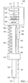
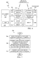
- FIGURE 1 illustrates an example apparatus 100, in accordance with certain embodiments.
- Apparatus 100 includes a pin 105, a housing 110, a stop 115, a spring 120, one or more flanges 125, and a measurement device 130.
- Pin 105 comprises a first end 135 and a second end 140.
- First end 135 is configured for insertion in an aperture in a component in which a fastener is intended to be used.
- Second end 140 is coupled to housing 110.
- pin 105 may be removably coupled to housing 110.
- Pin 105 may have any suitable shape and dimensions, and the shape and dimensions of pin 105 may vary according to different implementations of apparatus 100.
- pin 105 is sized to a specific diameter of the aperture being measured.
- pin 105 may be designed for use with different sized apertures, and the diameter of pin 105 may be slightly less than the diameter of the smallest aperture with which pin 105 may be used.
- pin 105 may have a shape and dimensions that correspond to the shape and dimensions of the aperture in which pin 105 is to be inserted. This may advantageously restrict movement of pin 105 as it moves in and out of the aperture in the component, thereby preventing differences in measurements due to variations in an amount of movement of pin 105 among operators.
- Pin 105 may be made from any suitable material.
- pin 105 may be made from metal (e.g., aluminum), rubber, or plastic (e.g., Delrin®), or any other suitable material or any suitable combination of materials.
- Stop 115 is slidably engaged with pin 105. Stop 115 is coupled to spring 120 and measurement device 130. Stop 115 is configured to contact a first surface of the component as pin 105 is inserted into the aperture in the component. Stop 115 may have any suitable dimensions and may be made of any suitable material. The dimensions and material forming stop 115 may vary according to different implementations of apparatus 100. As a particular example, stop 115 may be formed of rubber.
- Spring 120 couples stop 115 to housing 110. In its resting state, spring 120 is extended. In certain embodiments, in its resting state spring 120 may be extended such that stop 115 is substantially co-located with first end 135 of pin 105. In other words, spring 120 may have a substantially similar length as pin 105 when in its resting position. Spring 120 is configured to compress when stop 115 contacts the first surface of the component as pin 105 is inserted in the aperture in the component.
- One or more flanges 125 are located proximate to first end 135 of pin 105.
- One or more flanges 125 are configured to transition between a first retracted state during insertion of the pin and a second extended state when first end 135 of pin 105 passes through the aperture in the component.
- one or more flanges 125 are configured to contact a second surface of the component when in the second extended state.
- one or more flanges 125 are affixed to the exterior of pin 105 using one or more hinges.
- the hinges may be two-way spring-loaded hinges.
- one or more flanges 125 are located inside pin 105 when in the first retracted state.
- one or more flanges 125 may be configured to extend substantially perpendicular to an axis 190 of pin 105 such that they can contact the second surface of the component when in the second extended state.
- apparatus 100 may further comprise a mechanism for causing one or more flanges 125 to transition between the first retracted state and the second extended state.
- Measurement device 130 may be any suitable measurement device for determining a grip length of a fastener for use in the aperture of the component.
- measurement device 130 may be a linear displacement metrology device.
- measurement device 130 may be a capacitive displacement sensor.
- the grip length of a fastener refers to the length from the head of a fastener down to where the threads would start.
- grip length may be determined based at least in part on a depth of the aperture in the component.
- the grip length may be derived from a measurement of a distance from a first surface of the component through the aperture to a second surface of the component to obtain a stack thickness value.
- Further refinement of the stack thickness value may be performed to obtain the grip length.
- the refinement may be performed by software associated with measurement device 130 (e.g., circuitry 175), processing circuitry 145, or by another element on data received from apparatus 110 (e.g., receiving unit 605 described below in relation to FIGURE 6 ).
- measurement device 130 is a linear displacement metrology device.
- Linear displacement metrology device 130 includes a cylinder 165, a rod 170, and circuitry 175.
- Rod 170 has a first end 180 coupled to stop 115 and a second end 185 coupled to cylinder 165.
- Rod 170 is slidably engaged with cylinder 165.
- linear displacement metrology device (or, more generally, measurement device 130) may be oriented such that an axis 195 of measurement device 130 is parallel to axis 190 of pin 105.
- Circuitry 175 is configured to measure a distance that rod 170 has moved responsive to insertion of pin 105 into the aperture in the component. Circuitry 175 may be configured to translate a distance that rod 170 has moved relative to cylinder 165 into a measurement of the grip length of a fastener for use in the aperture in the component.
- Housing 110 is affixed proximate to second end 140 of pin 105.
- Housing 110 may be formed from any suitable material and may have any suitable shape.
- housing 110 may be formed of metal, plastic, any other suitable material or any suitable combination of materials.
- Housing 110 may include any suitable components.
- housing 110 includes processing circuitry 145, transmitter 150, receiver 155 and one or more memory devices 160.
- transmitter 150 is wireless.
- the functions of transmitter 150 and receiver 155 may be combined in a transceiver.
- processing circuitry 145, transmitter 150, receiver 155, and one or more memory devices 160 may be communicatively coupled to measurement device 130 or, more particularly with respect to the example embodiment illustrated in FIGURE 1 , to circuitry 175 of the linear displacement metrology device.
- Transmitter 150 may be configured to transmit a value indicating a determined grip length of a fastener for use in the aperture in the component.
- Processing circuitry 145, transmitter 150, receiver 155, and one or more memory devices 160 are described in more detail below in relation to FIGURE 6 .
- housing 110 may include additional components beyond those illustrated in FIGURE 1 .
- housing 110 may include an indicator light (such as an LED light) that provides an indication to an operator when a measurement has been completed.
- housing 110 may include a display (e.g., a digital readout or indicator light). The digital readout may, for example, display the determined grip length of the fastener for use in the component.
- the indicator light may provide an indication of whether measurement device 130 has obtained a successful measurement.
- pin 105 may be hollow and processing circuitry 145, transmitter 150, receiver 155, one or more memory devices 160 and the additional components described above may be included inside pin 105.
- an operator using apparatus 100 inserts first end 135 of pin 105 into an aperture in a component.
- stop 115 contacts a first surface of the component.
- one or more flanges 125 are in the first retracted state.
- pin 105 slides through stop 115, which remains pressed against the first surface of the component due to spring 120. More particularly, the movement of pin 105 while stop 115 is at rest against the first surface of the component causes compression of spring 120 (which applies force against stop 115 and causes stop 115 to remain in contact with the first surface of the component. The movement of pin 105 while stop 115 is at rest against the first surface of the component also causes rod 170 to move into cylinder 165 of measurement device 130.
- one or more flanges 125 are in a first retracted state.
- first end 135 of pin 105 exits the aperture in the component, one or more flanges 125 transition to a second extended state and contact a second surface of the component.
- the operator of apparatus 100 may release apparatus 100, and force applied by spring 120 causes apparatus 100 to claimp against the part due to a squeezing action between stop 115 at the first surface of the component and one or more flanges 125 at the second surface of the component.
- Measurement device 130 measures a grip length of a fastener for use in the aperture in the component based on the amount of movement of rod 170 relative to cylinder 165 when pin 105 was inserted into the aperture.
- apparatus 100 may include a timer.
- the measurement will be automatically recorded (e.g., in one or more memory devices 160) and transmitted by transmitter 150 toward a receiver (as described in more detail below in relation to FIGURE 6 ).
- a display may indicate whether a successful measurement has been performed (e.g., by displaying a digital readout of the measurement or illuminating an indicator light indicating a successful measurement). The operator may then remove pin 105 from the aperture.
- one or more flanges 125 will transition from the second extended state to a third retracted state (e.g., by collapsing outward when pin 105 is pulled back out of the aperture or by retracting into pin 105) to allow for removal.
- the third retracted state may be the same as the first retracted state.
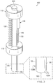
- FIGURE 2 illustrates another view of apparatus 100 of FIGURE 1 , in accordance with certain embodiments. More particularly, FIGURE 2 illustrates apparatus 100 and a close-up view of first end 135 of pin 105.
- apparatus 100 includes flanges 125A and 125B. As described above, flanges 125A and 125B may be configured to alternate between a first retracted state during insertion of pin 105 and a second extended state when first end 135 of pin 105 exits the aperture in the component. In the example of FIGURE 2 , flange 125A and flange 125B are shown in the second extended state.
- Flanges 125 may be coupled to pin 105 in any suitable manner.
- each of flange 125A and flange 125B may be coupled to pin 105 using a hinge, as described in more detail below in relation to FIGURE 3 .
- flanges 125A and 125B may be located inside pin 105 when in the first retracted state and configured to extend substantially perpendicular to axis 190 of pin 105 such that they can contact the second surface of the component when in the second extended state.
- apparatus 100 includes a mechanism 205 for causing flange 125A and flange 125B to transition from the first retracted state to the second extended state and from the second extended state to the first retracted state.
- Mechanism 205 may be any suitable mechanism.
- mechanism 205 may be a button, which when pressed a first time causes one or more flanges 125 to transition from the first retracted state to the second extended state.
- pressing the button a second time may cause one or more flanges 125 to transition to a third retracted state that is the same as the first retracted state.
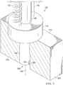
- FIGURE 3 illustrates apparatus 100 during a first stage of operation, in accordance with certain embodiments. More particularly, FIGURE 3 illustrates first end 135 of pin 105 of apparatus 100 in the initial stage of measuring a grip length of a fastener for use in a component 305.
- Component 305 has a first surface 310 and a second surface 315. Aperture 320 in component 305 runs through component 305 from first surface 310 to second surface 315.
- stop 115 contacts first surface 310. Because pin 105 is slidably engaged with stop 115, pin 105 continues to move through aperture 320 in component 305 toward second surface 315 while stop 115 remains in contact with first surface 310. This causes spring 120 to compress and apply force to stop 115, pressing stop 115 against first surface 310.
- flanges 125 are in the first retracted state as pin 105 moves through aperture 320 in component 305.
- flanges 125 are affixed to pin 105 using hinges 325 and, in the first retracted state, are flush against pin 105 and oriented substantially parallel to axis 190 of pin 105.
- flanges 125 may be located inside pin 105 when in the first retracted state.
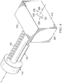
- FIGURE 4 illustrates apparatus 100 during a second stage of operation, in accordance with certain embodiments. More particularly, FIGURE 4 illustrates apparatus 100 after first end 135 of pin 105 has exited aperture 320 in component 305. As shown in the example embodiment of FIGURE 4 , as pin 105 passes through aperture 320 of component 305, flanges 125 transition from the first retracted state to a second extended state. In the second extended state, flanges 125 extend substantially perpendicular to axis 190 of pin 105 and contact second surface 315 of component 305.
- measurement device 130 may perform a measurement of the grip length of a fastener for use in aperture 320 of component 305.
- measurement device 130 may be a linear displacement metrology device.
- circuitry 175 of measurement device 130 may determine a grip length based on the movement of rod 170 relative to cylinder 165.
- measurement device 130 may send measurement information to processing circuitry in housing 110 (e.g., processing circuitry 145 described above in relation to FIGURE 1 ).
- the processing circuitry may utilize transmitter 150 to transmit a value indicating the measurement of the grip length of the fastener for use in aperture 320 (e.g., the actual measurement or any suitable indication thereof) to another component (e.g., a receiver in wireless communication with transmitter 150).
- measurement device 130 may wait to provide the measurement of grip length to the processing circuitry 145 until it reads a consistent measurement of the grip length for a certain period of time (e.g., as measured by a timer associated with measurement device 130).
- the period of time may be any suitable time period.
- the time period may be 0.5 seconds.
- the measurement information may be automatically provided upon expiration of the timer. This may advantageously require no additional action on the part of an operator of apparatus 100.
- apparatus 100 may provide an indication to the operator of apparatus 100 after successfully reading a measurement of the grip length.
- the indication may be provided in any suitable manner.
- the indication may be an LED light that indicates whether a measurement of the grip length has been successfully obtained (e.g., a green LED light may indicate a successful measurement).
- the indication may be an audible signal (e.g., a beep) that indicates to the operator of apparatus 100 that a measurement of the grip length has been successfully obtained.
- FIGURE 5 illustrates apparatus 100 during a third stage of operation, in accordance with certain embodiments. More particularly, FIGURE 5 illustrates pin 105 being removed from aperture 320 in component 305. The stage of operation illustrated in FIGURE 5 may, for example, occur after a successful measurement of the grip length of a fastener for use in aperture 320 in component 305 has been obtained.
- flanges 125 are shown in a third retracted state as pin 105 moves out of aperture 320 in component 305.
- flanges 125 are affixed to pin 105 using hinges 325.
- hinges 325 As pin 105 is removed from aperture 320 in component 305, flanges 125 transition to the third retracted state.
- flanges 125 In the third retracted state, flanges 125 are oriented toward second surface 315 of component 305 and substantially parallel to axis 190 of pin 105. This may advantageously enable pin 105 to be easily removed from aperture 320 in component 305.
- flanges 125 may be located inside pin 105 when in the third retracted state. Similar to the transition from the first retracted state to the second extended state described above in relation to FIGURE 2 , an operator may use a mechanism, such as mechanism 205 described above, to transition flanges 125 from the second extended state to the third retracted state.
- mechanism 205 is a button
- the operator may press the button a second time (the first time being when the button was depressed to cause the transition from the first retracted state to the second extended state, as described above in relation to FIGURE 2 ) in order to cause flanges 125 to transition from the second extended state to the third retracted state.
- the third retracted state may be the same as the first retracted state.
- FIGURE 6 is a schematic diagram of a system employing the example apparatus of FIGURE 1 , in accordance with certain embodiments.
- System 600 includes apparatus 100 and receiving unit 605.
- Apparatus 100 includes housing 110 and measurement device 130.
- housing 110 includes processing circuitry 145, transmitter 150, receiver 155, one or more memory devices 160, antenna 610 and display 615.
- Measurement device 130 includes timer 620. As described above, in certain embodiments the functions of transmitter 150 and receiver 155 may be combined into a transceiver. In some cases, housing 110 may not include receiver 155.
- measurement device 130 is communicatively coupled to processing circuitry 145 in housing 110. Although depicted in FIGURE 6 as located outside housing 110, in certain embodiments one or more components of measurement device 130 may be included in housing 110. For example, in certain embodiments circuitry 175 described above may be contained in housing 110. In addition, apparatus 100 may include the various additional elements of apparatus 100 described above in relation to FIGURES 1-5 .
- Receiving unit 605 includes antenna 615, processing circuitry 645, transmitter 650, receiver 655, and one or more memory devices 660. In certain embodiments, receiving unit 605 may not include transmitter 650. Receiving unit 605 may include additional elements beyond those shown in FIGURE 6 . For example, in certain embodiments receiving unit 605 may include an input device (e.g., a keyboard, touchscreen, or other suitable input device) and a display device.
- an input device e.g., a keyboard, touchscreen, or other suitable input device
- Processing circuitry 145 may be any electronic circuitry, including, but not limited to microprocessors, application specific integrated circuits (ASIC), application specific instruction set processor (ASIP), and/or state machines, that communicatively couples to one or more of measurement device 130, transmitter 150, receiver 155 (or, in some cases, a transceiver), one or more memory devices 160, display 615, and timer 620 and controls one or more operations of apparatus 100.
- Processing circuitry 145 may be 8-bit, 16-bit, 32-bit, 64-bit or of any other suitable architecture.
- Processing circuitry 145 may include an arithmetic logic unit (ALU) for performing arithmetic and logic operations, processor registers that supply operands to the ALU and store the results of ALU operations, and a control unit that fetches instructions from one or more memory devices 160 and executes them by directing the coordinated operations of the ALU, registers and other components.
- Processing circuitry 145 may include other hardware and software that operates to control and process information.
- Processing circuitry 145 executes software stored on one or more memory devices 160 to perform any of the functions described herein.
- Processing circuitry 145 controls one or more operations of apparatus 100 by processing information received by or from measurement device 130, transmitter 150, receiver 155, and one or more memory devices 160.
- Processing circuitry 145 may be a programmable logic device, a microcontroller, a microprocessor, any suitable processing device, or any suitable combination of the preceding. Processing circuitry 145 is not limited to a single processing device and may encompass multiple processing devices.
- Transmitter 150 and receiver 155 facilitate transmitting wireless signals from apparatus 100 to receiving unit 605 and receiving wireless signals at apparatus 100 from receiving unit 605, respectively.
- Transmitter 150 and receiver 155 may be any suitable devices operable to transmit and receive information, respectively. In some cases, transmitter 150 and receiver 155 may perform suitable processing of the information, communicate to other devices in addition to receiving unit 605, or any combination of the preceding. For example, transmitter 150 may transmit a value indicating a determined measurement of grip length of a fastener (e.g., the determined measurement or any suitable indication thereof) to a computing device, such as receiving unit 605 and/or any other suitable component. Receiver 155 may receive data from receiving unit 605 and/or any other suitable component. Transmitter 150 and receiver 155 may include any suitable hardware and/or software, including protocol conversion and data processing capabilities, to communicate through a LAN, WAN, or other communication systems that allows apparatus 100 to exchange information with other components.
- Transmitter 150 may be communicatively coupled to measurement device 130. Transmitter 150 is configured to communicate to receiving unit 605 a value indicating a determined grip length of a fastener for use in the aperture in the component.
- One or more memory devices 160 may store, either permanently or temporarily, data (e.g., determined measurements of grip length), operational software, or other information for processing circuitry 145.
- One or more memory devices 160 may include any one or a combination of volatile or non-volatile local or remote devices suitable for storing information.
- one or more memory devices 160 may include random access memory (RAM), read only memory (ROM), magnetic storage devices, optical storage devices, or any other suitable information storage device or a combination of these devices.
- the software represents any suitable set of instructions, logic, or code embodied in a computer-readable storage medium.
- the software may be embodied in memory 120, a disk, a compact disc (CD), or a flash drive.
- the software may include an application executable by processing circuitry 145 to perform one or more of the functions of apparatus 100 described herein.
- Display 615 may be any suitable display.
- display 615 may be a digital readout or an indicator light (e.g., an LED light).
- display 615 may indicate whether a successful measurement has been performed (e.g., by displaying a digital readout of the measurement or illuminating an indicator light indicating a successful measurement).
- the indication may be provided in any suitable manner.
- the indication may be an LED light that indicates whether a measurement of the grip length has been successfully obtained (e.g., a green LED light may indicate a successful measurement).
- apparatus 100 may include any suitable combination of hardware or software to provide an audible indication to an operator of apparatus 100.
- the indication may be an audible signal (e.g., a beep) that indicates to the operator of apparatus 100 that a measurement of the grip length has been successfully obtained.
- Measurement device 130 may use timer 620 to determine when to send measurement information.
- measurement device 130 may wait to provide a measurement of grip length to processing circuitry 145 until it reads a consistent measurement of the grip length for a certain period of time (e.g., as measured by timer 620 associated with measurement device 130).
- the period of time may be any suitable time period.
- the time period may be 0.5 seconds.
- the measurement information may be automatically provided upon expiration of timer 620.
- Processing circuitry 645, transmitter 650, receiver 655, and one or more memory devices 660 of receiving unit 605 may have analogous characteristics to processing circuitry 145, transmitter 150, receiver 155, and one or more memory devices 160 described above.
- these components of receiving unit 605 may be implemented using any of the hardware/software described above with respect to apparatus 100. Thus, for the sake of brevity, only differences will be described.
- processing circuitry 645 communicatively couples to one or more of transmitter 650, receiver 655 (or, in some cases, a transceiver), and one or more memory devices 660 and controls one or more operations of receiving unit 605.
- Processing circuitry 645 executes software stored on one or more memory devices 660 to perform any of the functions of receiving unit 605 described herein.
- Processing circuitry 645 controls one or more operations of receiving unit 605 by processing information received by or from transmitter 650, receiver 655, and one or more memory devices 660.
- Transmitter 650 and receiver 655 (or, in certain embodiments, a transceiver) facilitate transmitting wireless signals to apparatus 100 from receiving unit 605 and receiving wireless signals at receiving unit 605 from apparatus 100, respectively.
- receiver 655 may receive a value indicating a measurement of grip length of a fastener (e.g., the actual measurement or any suitable indication thereof) from apparatus 100.
- One or more memory devices 660 may store, either permanently or temporarily, data (e.g., received measurements of grip length), operational software, or other information for processing circuitry 645.
- FIGURE 7 is a flow diagram of a method 700, in accordance with certain embodiments.
- Method 700 begins at step 704, where a first end of a pin of a grip gauge is inserted into an aperture in a component.
- the grip gauge may comprise: a pin having a first end configured for insertion in the aperture in the component; a stop slidably engaged with the pin and configured to contact a first surface of the component as the pin is inserted into the aperture in the component; a spring coupling the stop to the housing; one or more flanges located proximate to the first end of the pin, the one or more flanges configured to contact a second surface of the component; and a transmitter communicatively coupled to the linear displacement metrology device and configured to transmit a value indicating the determined grip length to the receiver.
- the grip gauge may comprise one or more flanges located proximate to the first end of the pin.
- the one or more flanges may be configured to contact a second surface of the component, and the one or more flanges may be configured to transition between a first retracted state during insertion of the pin and a second extended state when the first end of the pin passes through the aperture in the component.
- the one or more flanges may be affixed to the exterior of the pin using one or more hinges.
- the one or more flanges may be located inside the pin when in the first retracted state, and the one or more flanges may be configured to extend perpendicular to the pin such that they can contact the second surface of the component when in the second extended state.
- the method may comprise causing the one or more flanges to transition between the first retracted state and the second extended state.
- a grip length for a fastener to be used in the aperture in the component is determined, the grip length determined based on a measurement performed using a measurement device coupled to the pin of the grip gauge.
- the measurement device may comprise a linear displacement metrology device.
- the linear displacement metrology device may comprise: a cylinder; a rod having a first end coupled to the stop and a second end coupled to the cylinder, wherein the rod is slidably engaged with the cylinder.
- the method may comprise measuring a distance that the rod has moved responsive to insertion of the pin into the aperture, the distance that the rod has moved corresponding to the grip length.
- an indication of the determined grip length is transmitted to a receiver.
- transmitting the determined grip length to the receiver may comprise wirelessly transmitting the determined grip length to the receiver.
Description
- The present disclosure relates in general to measurement tools, and more particularly to a wireless fastener grip gauge.
- The manufacture of aircraft and other vehicles often requires the assembly of numerous components using fasteners. It is important that the fasteners installed have the right grip length in order to ensure that the component tightens down properly. If a component does not tighten down properly, gaps or areas of force concentration may arise that can cause fracturing. This can be problematic, especially when the assembly of aircraft or other vehicles is required to meet tight tolerances. Existing approaches suffer from certain deficiencies. For example, existing approaches to measuring grip length are manual and of questionable accuracy.
-
US 2008/104855 A1 discloses measuring the linear movement of a sleeve between a retracted position and an extended position by a sensor located inside the housing of the device. The distal end of the sleeve is provided with a flange to contact the surface whose distance from the device has to be measured. - In
US 5 013 318 A a pin with flanges at one end is inserted from that end into a hole in an object; during insertion the flanges are retracted, then they are extended to contact a distal surface of the object; a stop is provided with spring means to contact the external surface of the pin and to indicate on a scale of the pin the distance between end and stop. - According to embodiments of the present disclosure, disadvantages and problems associated with previous techniques for measuring grip length may be reduced or eliminated.
- An apparatus is disclosed according to the appended claims 1-9.
- Further, a method is disclosed as claimed in appended claims 10-14.
- For a more complete understanding of the disclosed embodiments and their features and advantages, reference is now made to the following description, taken in conjunction with the accompanying drawings, in which:
-
FIGURE 1 illustrates an example apparatus, in accordance with certain embodiments; -
FIGURE 2 illustrates another view of the example apparatus ofFIGURE 1 , in accordance with certain embodiments; -
FIGURE 3 illustrates the example apparatus ofFIGURE 1 during a first stage of operation, in accordance with certain embodiments; -
FIGURE 4 illustrates the example apparatus ofFIGURE 1 during a second stage of operation, in accordance with certain embodiments; -
FIGURE 5 illustrates the example apparatus ofFIGURE 1 during a third stage of operation, in accordance with certain embodiments; -
FIGURE 6 is a schematic diagram of a system employing the example apparatus ofFIGURE 1 , in accordance with certain embodiments; and -
FIGURE 7 is a flow diagram of a method utilizing the example apparatus ofFIGURE 1 , in accordance with certain embodiments. - As described above, it is important during the manufacturing process of aircraft and other vehicles or machinery that the fasteners installed into a drilled aperture are the right grip length in order to ensure that the part tightens down properly. If a part does not tighten down properly, there could be gaps that arise or areas of force concentration that can cause fracturing. Existing approaches to measuring grip length are manual and of questionable accuracy.
- One existing approach, for example, is a manual tool that consists of a hook and a slider. An operator hooks the gauge on the backside of the aperture and slides the slider up to the surface of the part. The location of the front end of the slider (as read by the operator) will indicate the length needed. Another existing approach consists of a depth gauge attached to a slider. An operator pulls back on a slider mechanism to reveal a hook. The hook is then placed on the backside of the aperture and the operator pushes the slide mechanism closed in order to clamp the hook to the part.
- There are a number of deficiencies associated with the above approaches. For example, the first solution is an entirely manual method that is susceptible to operator variation and misinterpretation, especially at the edges of the ranges for each value. The hooking operation can also lead to the gauge not being centered or perpendicular to the surface, which can cause measurements to be skewed. The second existing approach described above requires a number of motions and inputs from the operator in order to operate, and is very tiresome to operate due to poor ergonomic design. Similar to the first approach, the hooking operation can lead to the gauge not being centered or perpendicular to the surface, which can cause measurements to be skewed. Thus, there is a need for an improved apparatus, system, and method for measuring the required grip length for a fastener.
- The present disclosure contemplates various embodiments that may address these and other deficiencies associated with existing approaches. According to one example embodiment, an apparatus is disclosed. The apparatus comprises a pin, a housing, a stop, a spring, one or more flanges, a linear displacement metrology device, and a transmitter. The pin comprises a first end configured for insertion in an aperture in a component. The housing is affixed proximate to a second end of the pin. The stop is slidably engaged with the pin and configured to contact a first surface of the component as the pin is inserted into the aperture in the component. The spring couples the stop to the housing. The spring is configured to compress when the stop contacts the first surface of the component as the pin is inserted in the aperture in the component. The one or more flanges are located proximate to the first end of the pin. The one or more flanges are configured to transition between a first retracted state during insertion of the pin and a second extended state when the first end of the pin passes through the aperture in the component. The one or more flanges are configured to contact a second surface of the component when in the second extended state. The linear displacement metrology device is coupled to the pin such that an axis of the linear displacement metrology device is substantially aligned with an axis of the pin. The transmitter is communicatively coupled to the linear displacement metrology device. The transmitter is located in the housing and configured to communicate to a receiver a value indicating a grip length of a fastener for use in the aperture in the component.
- According to another example embodiment, a method is disclosed. The method comprises inserting a first end of the pin of the grip gauge into an aperture in a component. The method comprises determining a grip length for a fastener to be used in the aperture in the component, the grip length determined based on a measurement performed using a measurement device coupled to the pin of the grip gauge. The method comprises transmitting the determined grip length to a receiver.
- Certain embodiments may have one or more technical advantages. For example, certain embodiments may advantageously reduce the subjectivity of measurements due to variation among operators and reduce the number of operator motions required to operate the apparatus. For example, certain embodiments may only require the operator to insert the pin and then, due to the spring-flange mechanism and linear displacement metrology device (which may, in certain embodiments, include a timer), the apparatus measures the part and transmits the data on its own, thereby requiring the operator to simply move the pin from aperture to aperture. Other advantages may be readily apparent to one having skill in the art. Certain embodiments may have none, some, or all of the recited advantages.
-
FIGURE 1 illustrates anexample apparatus 100, in accordance with certain embodiments.Apparatus 100 includes apin 105, ahousing 110, astop 115, aspring 120, one ormore flanges 125, and ameasurement device 130. -
Pin 105 comprises afirst end 135 and asecond end 140.First end 135 is configured for insertion in an aperture in a component in which a fastener is intended to be used.Second end 140 is coupled tohousing 110. In certain embodiments, pin 105 may be removably coupled tohousing 110. -
Pin 105 may have any suitable shape and dimensions, and the shape and dimensions ofpin 105 may vary according to different implementations ofapparatus 100. For example, incertain embodiments pin 105 is sized to a specific diameter of the aperture being measured. As another example, incertain embodiments pin 105 may be designed for use with different sized apertures, and the diameter ofpin 105 may be slightly less than the diameter of the smallest aperture with whichpin 105 may be used. In certain embodiments, pin 105 may have a shape and dimensions that correspond to the shape and dimensions of the aperture in whichpin 105 is to be inserted. This may advantageously restrict movement ofpin 105 as it moves in and out of the aperture in the component, thereby preventing differences in measurements due to variations in an amount of movement ofpin 105 among operators.Pin 105 may be made from any suitable material. As particular examples,pin 105 may be made from metal (e.g., aluminum), rubber, or plastic (e.g., Delrin®), or any other suitable material or any suitable combination of materials. - Stop 115 is slidably engaged with
pin 105. Stop 115 is coupled tospring 120 andmeasurement device 130. Stop 115 is configured to contact a first surface of the component aspin 105 is inserted into the aperture in the component. Stop 115 may have any suitable dimensions and may be made of any suitable material. The dimensions andmaterial forming stop 115 may vary according to different implementations ofapparatus 100. As a particular example, stop 115 may be formed of rubber. -
Spring 120 couples stop 115 tohousing 110. In its resting state,spring 120 is extended. In certain embodiments, in its restingstate spring 120 may be extended such thatstop 115 is substantially co-located withfirst end 135 ofpin 105. In other words,spring 120 may have a substantially similar length aspin 105 when in its resting position.Spring 120 is configured to compress when stop 115 contacts the first surface of the component aspin 105 is inserted in the aperture in the component. - One or
more flanges 125 are located proximate tofirst end 135 ofpin 105. One ormore flanges 125 are configured to transition between a first retracted state during insertion of the pin and a second extended state whenfirst end 135 ofpin 105 passes through the aperture in the component. As described in more detail below, one ormore flanges 125 are configured to contact a second surface of the component when in the second extended state. In certain embodiments, one ormore flanges 125 are affixed to the exterior ofpin 105 using one or more hinges. In certain embodiments, the hinges may be two-way spring-loaded hinges. - In certain embodiments, one or
more flanges 125 are located insidepin 105 when in the first retracted state. In such a scenario, one ormore flanges 125 may be configured to extend substantially perpendicular to anaxis 190 ofpin 105 such that they can contact the second surface of the component when in the second extended state. As described in more detail below in relation toFIGURE 2 , incertain embodiments apparatus 100 may further comprise a mechanism for causing one ormore flanges 125 to transition between the first retracted state and the second extended state. -
Measurement device 130 may be any suitable measurement device for determining a grip length of a fastener for use in the aperture of the component. For example, in certainembodiments measurement device 130 may be a linear displacement metrology device. As another example, in certainembodiments measurement device 130 may be a capacitive displacement sensor. As used herein, the grip length of a fastener refers to the length from the head of a fastener down to where the threads would start. In certain embodiments, grip length may be determined based at least in part on a depth of the aperture in the component. In certain embodiments, the grip length may be derived from a measurement of a distance from a first surface of the component through the aperture to a second surface of the component to obtain a stack thickness value. Further refinement of the stack thickness value may be performed to obtain the grip length. In certain embodiments, the refinement may be performed by software associated with measurement device 130 (e.g., circuitry 175),processing circuitry 145, or by another element on data received from apparatus 110 (e.g., receivingunit 605 described below in relation toFIGURE 6 ). - In the example embodiment of
FIGURE 1 ,measurement device 130 is a linear displacement metrology device. Lineardisplacement metrology device 130 includes acylinder 165, arod 170, andcircuitry 175.Rod 170 has afirst end 180 coupled to stop 115 and asecond end 185 coupled tocylinder 165.Rod 170 is slidably engaged withcylinder 165. In certain embodiments, linear displacement metrology device (or, more generally, measurement device 130) may be oriented such that anaxis 195 ofmeasurement device 130 is parallel toaxis 190 ofpin 105. -
Circuity 175 is configured to measure a distance thatrod 170 has moved responsive to insertion ofpin 105 into the aperture in the component.Circuitry 175 may be configured to translate a distance thatrod 170 has moved relative tocylinder 165 into a measurement of the grip length of a fastener for use in the aperture in the component. -
Housing 110 is affixed proximate tosecond end 140 ofpin 105.Housing 110 may be formed from any suitable material and may have any suitable shape. For example,housing 110 may be formed of metal, plastic, any other suitable material or any suitable combination of materials.Housing 110 may include any suitable components. In the example embodiment ofFIGURE 1 ,housing 110 includesprocessing circuitry 145,transmitter 150,receiver 155 and one ormore memory devices 160. In some cases,transmitter 150 is wireless. In certain embodiments, the functions oftransmitter 150 andreceiver 155 may be combined in a transceiver. One or more ofprocessing circuitry 145,transmitter 150,receiver 155, and one ormore memory devices 160 may be communicatively coupled tomeasurement device 130 or, more particularly with respect to the example embodiment illustrated inFIGURE 1 , tocircuitry 175 of the linear displacement metrology device.Transmitter 150 may be configured to transmit a value indicating a determined grip length of a fastener for use in the aperture in the component.Processing circuitry 145,transmitter 150,receiver 155, and one ormore memory devices 160 are described in more detail below in relation toFIGURE 6 . - In certain embodiments,
housing 110 may include additional components beyond those illustrated inFIGURE 1 . For example, in certain embodiments housing 110 may include an indicator light (such as an LED light) that provides an indication to an operator when a measurement has been completed. As another example, in certain embodiments housing 110 may include a display (e.g., a digital readout or indicator light). The digital readout may, for example, display the determined grip length of the fastener for use in the component. The indicator light may provide an indication of whethermeasurement device 130 has obtained a successful measurement. - Although processing
circuitry 145,transmitter 150,receiver 155 and one ormore memory devices 160 are shown in the example ofFIGURE 1 inhousing 110, the present disclosure contemplates that other arrangements are possible. For example, incertain embodiments pin 105 may be hollow andprocessing circuitry 145,transmitter 150,receiver 155, one ormore memory devices 160 and the additional components described above may be included insidepin 105. - In operation, an
operator using apparatus 100 insertsfirst end 135 ofpin 105 into an aperture in a component. Asfirst end 135 ofpin 105 is inserted into the aperture, stop 115 contacts a first surface of the component. At this stage of operation, one ormore flanges 125 are in the first retracted state. Aspin 105 is further inserted into the aperture, pin 105 slides throughstop 115, which remains pressed against the first surface of the component due tospring 120. More particularly, the movement ofpin 105 whilestop 115 is at rest against the first surface of the component causes compression of spring 120 (which applies force againststop 115 and causes stop 115 to remain in contact with the first surface of the component. The movement ofpin 105 whilestop 115 is at rest against the first surface of the component also causesrod 170 to move intocylinder 165 ofmeasurement device 130. - As
pin 105 passes through the aperture in the component, one ormore flanges 125 are in a first retracted state. Whenfirst end 135 ofpin 105 exits the aperture in the component, one ormore flanges 125 transition to a second extended state and contact a second surface of the component. At this point, the operator ofapparatus 100 may releaseapparatus 100, and force applied byspring 120 causesapparatus 100 to claimp against the part due to a squeezing action betweenstop 115 at the first surface of the component and one ormore flanges 125 at the second surface of the component. Measurement device 130 (i.e., lineardisplacement metrology device 130 in the example embodiment ofFIGURE 1 ) measures a grip length of a fastener for use in the aperture in the component based on the amount of movement ofrod 170 relative tocylinder 165 whenpin 105 was inserted into the aperture. - In certain embodiments,
apparatus 100 may include a timer. In such a scenario, after a set amount of time passes (e.g., the timer expires) withmeasurement device 130 reading a constant measurement of grip length, the measurement will be automatically recorded (e.g., in one or more memory devices 160) and transmitted bytransmitter 150 toward a receiver (as described in more detail below in relation toFIGURE 6 ). In some cases, a display may indicate whether a successful measurement has been performed (e.g., by displaying a digital readout of the measurement or illuminating an indicator light indicating a successful measurement). The operator may then removepin 105 from the aperture. Aspin 105 is removed, one ormore flanges 125 will transition from the second extended state to a third retracted state (e.g., by collapsing outward whenpin 105 is pulled back out of the aperture or by retracting into pin 105) to allow for removal. In certain embodiments in which one ormore flanges 125 are located withinpin 105 in the first retracted state, the third retracted state may be the same as the first retracted state. -
FIGURE 2 illustrates another view ofapparatus 100 ofFIGURE 1 , in accordance with certain embodiments. More particularly,FIGURE 2 illustratesapparatus 100 and a close-up view offirst end 135 ofpin 105. As shown in the example ofFIGURE 2 ,apparatus 100 includesflanges flanges pin 105 and a second extended state whenfirst end 135 ofpin 105 exits the aperture in the component. In the example ofFIGURE 2 ,flange 125A andflange 125B are shown in the second extended state. -
Flanges 125 may be coupled to pin 105 in any suitable manner. For example, in certain embodiments each offlange 125A andflange 125B may be coupled to pin 105 using a hinge, as described in more detail below in relation toFIGURE 3 . As another example, and as shown in the example ofFIGURE 2 ,flanges pin 105 when in the first retracted state and configured to extend substantially perpendicular toaxis 190 ofpin 105 such that they can contact the second surface of the component when in the second extended state. - In the example of
FIGURE 2 ,apparatus 100 includes amechanism 205 for causingflange 125A andflange 125B to transition from the first retracted state to the second extended state and from the second extended state to the first retracted state.Mechanism 205 may be any suitable mechanism. For example,mechanism 205 may be a button, which when pressed a first time causes one ormore flanges 125 to transition from the first retracted state to the second extended state. In certain embodiments (as described in more detail below in relation toFIGURE 5 ), pressing the button a second time may cause one ormore flanges 125 to transition to a third retracted state that is the same as the first retracted state. -
FIGURE 3 illustratesapparatus 100 during a first stage of operation, in accordance with certain embodiments. More particularly,FIGURE 3 illustratesfirst end 135 ofpin 105 ofapparatus 100 in the initial stage of measuring a grip length of a fastener for use in acomponent 305.Component 305 has afirst surface 310 and asecond surface 315.Aperture 320 incomponent 305 runs throughcomponent 305 fromfirst surface 310 tosecond surface 315. - As
pin 105 is inserted intoaperture 320 incomponent 305 and moves towardsecond surface 315, stop 115 contactsfirst surface 310. Becausepin 105 is slidably engaged withstop 115,pin 105 continues to move throughaperture 320 incomponent 305 towardsecond surface 315 whilestop 115 remains in contact withfirst surface 310. This causesspring 120 to compress and apply force to stop 115, pressing stop 115 againstfirst surface 310. - As shown in the example of
FIGURE 3 ,flanges 125 are in the first retracted state aspin 105 moves throughaperture 320 incomponent 305. In the example embodiment ofFIGURE 3 ,flanges 125 are affixed to pin 105 usinghinges 325 and, in the first retracted state, are flush againstpin 105 and oriented substantially parallel toaxis 190 ofpin 105. As described above, incertain embodiments flanges 125 may be located insidepin 105 when in the first retracted state. -
FIGURE 4 illustratesapparatus 100 during a second stage of operation, in accordance with certain embodiments. More particularly,FIGURE 4 illustratesapparatus 100 afterfirst end 135 ofpin 105 has exitedaperture 320 incomponent 305. As shown in the example embodiment ofFIGURE 4 , aspin 105 passes throughaperture 320 ofcomponent 305,flanges 125 transition from the first retracted state to a second extended state. In the second extended state,flanges 125 extend substantially perpendicular toaxis 190 ofpin 105 and contactsecond surface 315 ofcomponent 305. - As described above,
spring 120 compresses asstop 115 contacts first surface 310 ofcomponent 305 aspin 105 passes throughaperture 320 ofcomponent 305. Whenflanges 125 enter the second extended state and contactsecond surface 315 ofcomponent 305, force applied byspring 115 causesapparatus 100 to clampcomponent 305 betweenstop 115 andflanges 125. At this point,measurement device 130 may perform a measurement of the grip length of a fastener for use inaperture 320 ofcomponent 305. As described above, in certainembodiments measurement device 130 may be a linear displacement metrology device. In such a scenario,circuitry 175 ofmeasurement device 130 may determine a grip length based on the movement ofrod 170 relative tocylinder 165. - In certain embodiments,
measurement device 130 may send measurement information to processing circuitry in housing 110 (e.g., processingcircuitry 145 described above in relation toFIGURE 1 ). The processing circuitry may utilizetransmitter 150 to transmit a value indicating the measurement of the grip length of the fastener for use in aperture 320 (e.g., the actual measurement or any suitable indication thereof) to another component (e.g., a receiver in wireless communication with transmitter 150). - In certain embodiments,
measurement device 130 may wait to provide the measurement of grip length to theprocessing circuitry 145 until it reads a consistent measurement of the grip length for a certain period of time (e.g., as measured by a timer associated with measurement device 130). The period of time may be any suitable time period. For example, in certain embodiments the time period may be 0.5 seconds. In some cases, the measurement information may be automatically provided upon expiration of the timer. This may advantageously require no additional action on the part of an operator ofapparatus 100. - In some cases,
apparatus 100 may provide an indication to the operator ofapparatus 100 after successfully reading a measurement of the grip length. The indication may be provided in any suitable manner. As one example, the indication may be an LED light that indicates whether a measurement of the grip length has been successfully obtained (e.g., a green LED light may indicate a successful measurement). As another example, the indication may be an audible signal (e.g., a beep) that indicates to the operator ofapparatus 100 that a measurement of the grip length has been successfully obtained. -
FIGURE 5 illustratesapparatus 100 during a third stage of operation, in accordance with certain embodiments. More particularly,FIGURE 5 illustratespin 105 being removed fromaperture 320 incomponent 305. The stage of operation illustrated inFIGURE 5 may, for example, occur after a successful measurement of the grip length of a fastener for use inaperture 320 incomponent 305 has been obtained. - As shown in the example of
FIGURE 5 ,flanges 125 are shown in a third retracted state aspin 105 moves out ofaperture 320 incomponent 305. In the example embodiment ofFIGURE 5 ,flanges 125 are affixed to pin 105 using hinges 325. Aspin 105 is removed fromaperture 320 incomponent 305,flanges 125 transition to the third retracted state. In the third retracted state,flanges 125 are oriented towardsecond surface 315 ofcomponent 305 and substantially parallel toaxis 190 ofpin 105. This may advantageously enablepin 105 to be easily removed fromaperture 320 incomponent 305. - In certain embodiments,
flanges 125 may be located insidepin 105 when in the third retracted state. Similar to the transition from the first retracted state to the second extended state described above in relation toFIGURE 2 , an operator may use a mechanism, such asmechanism 205 described above, to transitionflanges 125 from the second extended state to the third retracted state. For example, in embodiments in whichmechanism 205 is a button, the operator may press the button a second time (the first time being when the button was depressed to cause the transition from the first retracted state to the second extended state, as described above in relation toFIGURE 2 ) in order to causeflanges 125 to transition from the second extended state to the third retracted state. In such a scenario, the third retracted state may be the same as the first retracted state. -
FIGURE 6 is a schematic diagram of a system employing the example apparatus ofFIGURE 1 , in accordance with certain embodiments.System 600 includesapparatus 100 and receivingunit 605.Apparatus 100 includeshousing 110 andmeasurement device 130. In the example embodiment ofFIGURE 6 ,housing 110 includesprocessing circuitry 145,transmitter 150,receiver 155, one ormore memory devices 160,antenna 610 anddisplay 615.Measurement device 130 includestimer 620. As described above, in certain embodiments the functions oftransmitter 150 andreceiver 155 may be combined into a transceiver. In some cases,housing 110 may not includereceiver 155. - In the example embodiment of
FIGURE 6 ,measurement device 130 is communicatively coupled toprocessing circuitry 145 inhousing 110. Although depicted inFIGURE 6 as located outsidehousing 110, in certain embodiments one or more components ofmeasurement device 130 may be included inhousing 110. For example, incertain embodiments circuitry 175 described above may be contained inhousing 110. In addition,apparatus 100 may include the various additional elements ofapparatus 100 described above in relation toFIGURES 1-5 . - Receiving
unit 605 includesantenna 615,processing circuitry 645,transmitter 650,receiver 655, and one ormore memory devices 660. In certain embodiments, receivingunit 605 may not includetransmitter 650. Receivingunit 605 may include additional elements beyond those shown inFIGURE 6 . For example, in certainembodiments receiving unit 605 may include an input device (e.g., a keyboard, touchscreen, or other suitable input device) and a display device. -
Processing circuitry 145 may be any electronic circuitry, including, but not limited to microprocessors, application specific integrated circuits (ASIC), application specific instruction set processor (ASIP), and/or state machines, that communicatively couples to one or more ofmeasurement device 130,transmitter 150, receiver 155 (or, in some cases, a transceiver), one ormore memory devices 160,display 615, andtimer 620 and controls one or more operations ofapparatus 100.Processing circuitry 145 may be 8-bit, 16-bit, 32-bit, 64-bit or of any other suitable architecture.Processing circuitry 145 may include an arithmetic logic unit (ALU) for performing arithmetic and logic operations, processor registers that supply operands to the ALU and store the results of ALU operations, and a control unit that fetches instructions from one ormore memory devices 160 and executes them by directing the coordinated operations of the ALU, registers and other components.Processing circuitry 145 may include other hardware and software that operates to control and process information.Processing circuitry 145 executes software stored on one ormore memory devices 160 to perform any of the functions described herein.Processing circuitry 145 controls one or more operations ofapparatus 100 by processing information received by or frommeasurement device 130,transmitter 150,receiver 155, and one ormore memory devices 160.Processing circuitry 145 may be a programmable logic device, a microcontroller, a microprocessor, any suitable processing device, or any suitable combination of the preceding.Processing circuitry 145 is not limited to a single processing device and may encompass multiple processing devices. -
Transmitter 150 and receiver 155 (or, in certain embodiments, a transceiver) facilitate transmitting wireless signals fromapparatus 100 to receivingunit 605 and receiving wireless signals atapparatus 100 from receivingunit 605, respectively.Transmitter 150 andreceiver 155 may be any suitable devices operable to transmit and receive information, respectively. In some cases,transmitter 150 andreceiver 155 may perform suitable processing of the information, communicate to other devices in addition to receivingunit 605, or any combination of the preceding. For example,transmitter 150 may transmit a value indicating a determined measurement of grip length of a fastener (e.g., the determined measurement or any suitable indication thereof) to a computing device, such as receivingunit 605 and/or any other suitable component.Receiver 155 may receive data from receivingunit 605 and/or any other suitable component.Transmitter 150 andreceiver 155 may include any suitable hardware and/or software, including protocol conversion and data processing capabilities, to communicate through a LAN, WAN, or other communication systems that allowsapparatus 100 to exchange information with other components. -
Transmitter 150 may be communicatively coupled tomeasurement device 130.Transmitter 150 is configured to communicate to receiving unit 605 a value indicating a determined grip length of a fastener for use in the aperture in the component. - One or
more memory devices 160 may store, either permanently or temporarily, data (e.g., determined measurements of grip length), operational software, or other information forprocessing circuitry 145. One ormore memory devices 160 may include any one or a combination of volatile or non-volatile local or remote devices suitable for storing information. For example, one ormore memory devices 160 may include random access memory (RAM), read only memory (ROM), magnetic storage devices, optical storage devices, or any other suitable information storage device or a combination of these devices. The software represents any suitable set of instructions, logic, or code embodied in a computer-readable storage medium. For example, the software may be embodied inmemory 120, a disk, a compact disc (CD), or a flash drive. In particular embodiments, the software may include an application executable by processingcircuitry 145 to perform one or more of the functions ofapparatus 100 described herein. -
Display 615 may be any suitable display. For example, in certain embodiments display 615 may be a digital readout or an indicator light (e.g., an LED light). In some cases,display 615 may indicate whether a successful measurement has been performed (e.g., by displaying a digital readout of the measurement or illuminating an indicator light indicating a successful measurement). The indication may be provided in any suitable manner. As one example, the indication may be an LED light that indicates whether a measurement of the grip length has been successfully obtained (e.g., a green LED light may indicate a successful measurement). In certain embodiments,apparatus 100 may include any suitable combination of hardware or software to provide an audible indication to an operator ofapparatus 100. For example, the indication may be an audible signal (e.g., a beep) that indicates to the operator ofapparatus 100 that a measurement of the grip length has been successfully obtained. -
Measurement device 130 may usetimer 620 to determine when to send measurement information. In certain embodiments,measurement device 130 may wait to provide a measurement of grip length toprocessing circuitry 145 until it reads a consistent measurement of the grip length for a certain period of time (e.g., as measured bytimer 620 associated with measurement device 130). The period of time may be any suitable time period. For example, in certain embodiments the time period may be 0.5 seconds. In some cases, the measurement information may be automatically provided upon expiration oftimer 620. -
Processing circuitry 645,transmitter 650,receiver 655, and one ormore memory devices 660 of receivingunit 605 may have analogous characteristics toprocessing circuitry 145,transmitter 150,receiver 155, and one ormore memory devices 160 described above. For example, these components of receivingunit 605 may be implemented using any of the hardware/software described above with respect toapparatus 100. Thus, for the sake of brevity, only differences will be described. - In the example embodiment of
FIGURE 6 ,processing circuitry 645 communicatively couples to one or more oftransmitter 650, receiver 655 (or, in some cases, a transceiver), and one ormore memory devices 660 and controls one or more operations of receivingunit 605.Processing circuitry 645 executes software stored on one ormore memory devices 660 to perform any of the functions of receivingunit 605 described herein.Processing circuitry 645 controls one or more operations of receivingunit 605 by processing information received by or fromtransmitter 650,receiver 655, and one ormore memory devices 660. -
Transmitter 650 and receiver 655 (or, in certain embodiments, a transceiver) facilitate transmitting wireless signals toapparatus 100 from receivingunit 605 and receiving wireless signals at receivingunit 605 fromapparatus 100, respectively. In certain embodiments,receiver 655 may receive a value indicating a measurement of grip length of a fastener (e.g., the actual measurement or any suitable indication thereof) fromapparatus 100. - One or
more memory devices 660 may store, either permanently or temporarily, data (e.g., received measurements of grip length), operational software, or other information forprocessing circuitry 645. -
FIGURE 7 is a flow diagram of amethod 700, in accordance with certain embodiments.Method 700 begins atstep 704, where a first end of a pin of a grip gauge is inserted into an aperture in a component. In certain embodiments, the grip gauge may comprise: a pin having a first end configured for insertion in the aperture in the component; a stop slidably engaged with the pin and configured to contact a first surface of the component as the pin is inserted into the aperture in the component; a spring coupling the stop to the housing; one or more flanges located proximate to the first end of the pin, the one or more flanges configured to contact a second surface of the component; and a transmitter communicatively coupled to the linear displacement metrology device and configured to transmit a value indicating the determined grip length to the receiver. - In certain embodiments, the grip gauge may comprise one or more flanges located proximate to the first end of the pin. The one or more flanges may be configured to contact a second surface of the component, and the one or more flanges may be configured to transition between a first retracted state during insertion of the pin and a second extended state when the first end of the pin passes through the aperture in the component. In certain embodiments, the one or more flanges may be affixed to the exterior of the pin using one or more hinges. In certain embodiments, the one or more flanges may be located inside the pin when in the first retracted state, and the one or more flanges may be configured to extend perpendicular to the pin such that they can contact the second surface of the component when in the second extended state. The method may comprise causing the one or more flanges to transition between the first retracted state and the second extended state.
- At
step 708, a grip length for a fastener to be used in the aperture in the component is determined, the grip length determined based on a measurement performed using a measurement device coupled to the pin of the grip gauge. In certain embodiments, the measurement device may comprise a linear displacement metrology device. The linear displacement metrology device may comprise: a cylinder; a rod having a first end coupled to the stop and a second end coupled to the cylinder, wherein the rod is slidably engaged with the cylinder. The method may comprise measuring a distance that the rod has moved responsive to insertion of the pin into the aperture, the distance that the rod has moved corresponding to the grip length. - At
step 712, an indication of the determined grip length is transmitted to a receiver. In certain embodiments, transmitting the determined grip length to the receiver may comprise wirelessly transmitting the determined grip length to the receiver. Modifications, additions, or omissions may be made to the systems and apparatuses described herein without departing from the scope of the disclosure. The components of the systems and apparatuses may be integrated or separated. Moreover, the operations of the systems and apparatuses may be performed by more, fewer, or other components. Additionally, operations of the systems and apparatuses may be performed using any suitable logic comprising software, hardware, and/or other logic. As used in this document, "each" refers to each member of a set or each member of a subset of a set. - Modifications, additions, or omissions may be made to the methods described herein without departing from the scope of the disclosure. The methods may include more, fewer, or other steps.
Claims (14)
- An apparatus (100) for ascertaining the grip length of a fastener for use in a component (305), comprising:a pin (105) comprising a first end (135) configured for insertion in an aperture (320) in a component (305) which runs from a first surface (310) of the component (305) to a second surface (315) of the component (305);a housing (110) affixed proximate to a second end (140) of the pin (105);a stop (115) slidably engaged with the pin (105) and configured to contact the first surface (310) of the component as the pin (105) is inserted into the aperture (320) in the component (305);a spring (120) coupling the stop (115) to the housing (110);one or more flanges (125) located proximate to the first end (135) of the pin (105), the one or more flanges (125) configured to contact the second surface (315) of the component (305);a measurement device (130) coupled to the pin (105); anda transmitter (150) communicatively coupled to the measurement device (130) and configured to communicate to a receiver (155) a value indicating a grip length of a fastener for use in the aperture (320) in the component (305) based on the amount of movement of the first end (135) of the pin (105) between the first surface (310) and the second surface (315).
- An apparatus (100) of claim 1, wherein:the spring (120) is configured to compress when the stop (115) contacts the first surface (310) of the component (305) as the pin (105) is inserted in the aperture (320) in the component (305); andthe one or more flanges (125) are configured to transition between a first retracted state during insertion of the pin (105) and a second extended state when the first end (135) of the pin (105) passes through the aperture (320) in the component (305), the one or more flanges (125) configured to contact the second surface (315) of the component (305) when in the second extended state;the linear displacement metrology device is coupled to the pin (105) such that an axis of the linear displacement metrology device is substantially aligned with an axis (190) of the pin (105); andthe transmitter (150) is located in the housing (110).
- The apparatus of claim 2, wherein the measurement device (130) comprises:
a linear differential transformer, comprising:a cylinder (165);a rod (170) having a first end (180) coupled to the stop (115) and a second end (185) coupled to the cylinder (165), wherein the rod is slidably engaged with the cylinder (165); andcircuitry (175) configured to measure a distance that the rod (170) has moved responsive to insertion of the pin (105) into the aperture (320), the distance that the rod (170) has moved corresponding to the grip length of the fastener for use in the aperture (320) in the component (305). - The apparatus (100) of claim 2 or of claim 3, wherein the transmitter (150) is a wireless transmitter.
- The apparatus (10) of claim 2 or of claim 3 or of claim 4, wherein the one or more flanges (125) are affixed to the exterior of the pin (105) using one or more hinges (325).
- The apparatus (100) of claim 2 or of any of claims 3 to 5, wherein:the one or more flanges (125) are located inside the pin (105) when in the first retracted state;the one or more flanges (125) are configured to extend perpendicular to the axis (190) of the pin (105) such that they can contact the second surface (315) of the component (305) when in the second extended state; andthe apparatus (100) comprises a mechanism for causing the one or more flanges (125) to transition between the first retracted state and the second extended state.
- The apparatus (100) of claim 1, wherein the spring (120) is configured to compress when the stop (115) contacts the first surface (310) of the component (305) during placement of the pin (105) in the aperture (320) in the component (305).
- The apparatus (100) of claim 1 or claim 7, wherein the one or more flanges (125) are configured to transition between a first retracted state during insertion of the pin (105) and a second extended state when the first end (135) of the pin (105) passes through the aperture (320) in the component (305), and optionally or preferably:-(i) wherein the one or more flanges are affixed to the exterior of the pin (105) using one or more hinges (325); and/or(ii) wherein:the one or more flanges are located inside the pin (105) when in the first retracted state;the one or more flanges (125) are configured to extend from the pin such that they contact the second surface (315) of the component (305) when in the second extended state; andthe grip gauge comprises a mechanism for causing the one or more flanges (125) to transition between the first retracted state and the second extended state.
- The apparatus (100) of claim 1 or of claim 7 or of claim 8, wherein:the transmitter (150) is located in the housing (110) affixed proximate to a second end (140) of the pin (105); andthe transmitter (150) is configured to communicate to a receiver (155) a value indicating a grip length of the aperture (320) in the component (305).
- A method for ascertaining a grip length of a fastener for use in a component (305), wherein the component (305) has an aperture (320) which runs from a first surface (310) of the component (305) to a second surface (315) of the component (305), using a grip gauge, wherein the grip gauge comprises:a pin (105) having a first end (135) configured for insertion in the aperture (320) of the component (305);a housing (110) affixed proximate to a second end (140) of the pin (105);a stop (115) slidably engaged with the pin (105) and configured to contact the first surface (310) of the component (305) as the pin is inserted into the aperture (320) in the component;a spring (120) coupling the stop (115) to the housing (110);one or more flanges (125) located proximate to the first end (135) of the pin (105), the one or more flanges configured to contact the second surface (315) of the component (305); andwherein the method comprises the steps of:inserting a first end (135) of the pin (105) of the grip gauge into the aperture (320) in the component (305) until the one or more flanges contact the second surface of the component (315); anddetermining a grip length for a fastener to be used in the aperture (320) in the component, the grip length determined by measuring the amount of movement of the first end (135) of the pin (105) between the first surface (310) and the second surface (315) of the component (305) based on a measurement performed using a measurement device coupled to the pin of the grip gauge; andtransmitting a value indicating the determined grip length to a receiver.
- The method of claim 10, wherein transmitting the value indicating the determined grip length to the receiver (155) comprises wirelessly transmitting the value indicating the determined grip length to the receiver.
- The method of claim 10 or of claim 11, wherein the grip gauge comprises:
a transmitter communicatively coupled to the linear displacement metrology device and configured to transmit the value indicating the determined grip length to the receiver; and optionally or preferably wherein the measurement device (130) comprises:
a linear displacement metrology device, comprising:a cylinder (165);a rod (170) having a first end (135) coupled to the stop (115) and a second end (185) coupled to the cylinder, wherein the rod is slidably engaged with the cylinder (165); andthe method comprises measuring a distance that the rod (170) has moved responsive to insertion of the pin (105) into the aperture (320), the distance that the rod (170) has moved corresponding to the grip length. - The method of claim 10 or of claim 11 or of claim 12, wherein the one or more flanges (125) configured to transition between a first retracted state during insertion of the pin and a second extended state when the first end (135) of the pin (105) passes through the aperture (320) in the component (305).
- The method of claim 13, wherein:-(i) the one or more flanges (125) are affixed to the exterior of the pin (105) using one or more hinges (325); or(ii) the one or more flanges are located inside the pin (105) when in the first retracted state; and
the one or more flanges (125) are configured to extend perpendicular to the pin (105) such that they can contact the second surface (315) of the component (305) when in the second extended state, and optionally or preferably further comprising:
causing the one or more flanges (125) to transition between the first retracted state and the second extended state.
Applications Claiming Priority (1)
| Application Number | Priority Date | Filing Date | Title |
|---|---|---|---|
| US15/472,784 US10330453B2 (en) | 2017-03-29 | 2017-03-29 | Wireless fastener grip gauge |
Publications (2)
| Publication Number | Publication Date |
|---|---|
| EP3382326A1 EP3382326A1 (en) | 2018-10-03 |
| EP3382326B1 true EP3382326B1 (en) | 2020-05-13 |
Family
ID=61763836
Family Applications (1)
| Application Number | Title | Priority Date | Filing Date |
|---|---|---|---|
| EP18163492.4A Active EP3382326B1 (en) | 2017-03-29 | 2018-03-22 | Apparatus and method for ascertaining the grip length of a fastener for use in a component |
Country Status (3)
| Country | Link |
|---|---|
| US (1) | US10330453B2 (en) |
| EP (1) | EP3382326B1 (en) |
| JP (1) | JP6817247B2 (en) |
Families Citing this family (4)
| Publication number | Priority date | Publication date | Assignee | Title |
|---|---|---|---|---|
| US10350759B2 (en) * | 2017-08-14 | 2019-07-16 | The Boeing Company | Alignment tool for fastener feed mechanism |
| US11313660B2 (en) | 2020-03-30 | 2022-04-26 | Lockheed Martin Corporation | Digital grip gauge with shaped tip |
| CN112729203B (en) * | 2021-01-21 | 2024-04-05 | 镇安芯木田科技有限公司 | Probe hole depth detection mechanism |
| CN115014303B (en) * | 2022-07-21 | 2023-08-01 | 湖南城建职业技术学院 | Indoor mapping device of building |
Family Cites Families (28)
| Publication number | Priority date | Publication date | Assignee | Title |
|---|---|---|---|---|
| US4112355A (en) | 1976-10-22 | 1978-09-05 | Lockheed Corporation | Quality and fit measuring apparatus for fasteners and their holes |
| US4216585A (en) * | 1978-09-26 | 1980-08-12 | Hi-Shear Corporation | Depth gage |
| US5013318A (en) | 1990-07-31 | 1991-05-07 | Special Devices Incorporated | Medical instrument for measuring depth of fastener hold in bone |
| US5095638A (en) * | 1990-10-05 | 1992-03-17 | Northrop Corporation | Method for assigning standard fasteners in accordance with a series of measurements |
| US5189808A (en) | 1991-06-03 | 1993-03-02 | The Boeing Company | Measurement gauge |
| US5580035A (en) | 1992-09-21 | 1996-12-03 | The Boeing Company | Clamp |
| IT1263452B (en) | 1993-07-01 | 1996-08-05 | Marposs Spa | BUFFER COMPARATOR. |
| US5657550A (en) * | 1994-10-12 | 1997-08-19 | Js Research And Development, Inc. | Hand-held gap and contour measuring gauge |
| US5497560A (en) | 1995-01-27 | 1996-03-12 | Pasquerella; David | Depth finder |
| US5673839A (en) | 1995-11-29 | 1997-10-07 | The Boeing Company | Real-time fastener measurement system |
| US6494848B1 (en) | 1996-12-19 | 2002-12-17 | St. Jude Medical Puerto Rico B.V. | Measuring device for use with a hemostatic puncture closure device |
| US6058598A (en) * | 1997-04-18 | 2000-05-09 | Huck International, Inc. | Control system for an assembly tool |
| DE50212349D1 (en) * | 2002-02-07 | 2008-07-17 | Synthes Gmbh | HIRURGIE |
| US6764453B2 (en) | 2002-05-08 | 2004-07-20 | Sherwood Services Ag | Stoma measuring device |
| US7065897B2 (en) | 2004-11-02 | 2006-06-27 | The Boeing Company | Fastener grip length selector |
| US20060116637A1 (en) | 2004-11-30 | 2006-06-01 | Kimberly-Clark Worldwide, Inc. | Tract measuring device having a unitary occluded tip and inflatable sock member and method of making the same |
| US7165336B2 (en) * | 2005-03-16 | 2007-01-23 | Eidosmed Llc | Surgical depth instrument |
| US7559150B2 (en) * | 2005-10-13 | 2009-07-14 | Synthes Usa, Llc | Depth gauge |
| US7665221B2 (en) | 2006-05-25 | 2010-02-23 | The Boeing Company | Method and apparatus for hole diameter profile measurement |
| US7607238B2 (en) * | 2006-11-07 | 2009-10-27 | Eidosmed Llc | Digital depth gauge |
| US8512349B2 (en) * | 2007-12-13 | 2013-08-20 | Richard A. Mengato | Apparatus for measuring depth of a bone opening and related method |
| US7895767B2 (en) | 2008-09-12 | 2011-03-01 | Eidosmed Llc | Electronic depth gauge with variable electrical resistance sensing |
| US7913414B2 (en) | 2009-03-18 | 2011-03-29 | The Boeing Company | Nut plate grip gage |
| US8606540B2 (en) | 2009-11-10 | 2013-12-10 | Projectionworks, Inc. | Hole measurement apparatuses |
| US8365428B2 (en) | 2010-12-15 | 2013-02-05 | Lockheed Martin Corporation | Hole grip length measurement apparatus |
| US8336222B1 (en) | 2011-06-27 | 2012-12-25 | The Boeing Company | Method and apparatus for measuring spaces with limited access |
| US9797707B2 (en) | 2014-01-08 | 2017-10-24 | The Boeing Company | Electronic gage apparatus |
| GB2533423A (en) | 2014-12-19 | 2016-06-22 | Airbus Operations Ltd | Method and apparatus for determining a hole depth |
-
2017
- 2017-03-29 US US15/472,784 patent/US10330453B2/en active Active
-
2018
- 2018-03-22 EP EP18163492.4A patent/EP3382326B1/en active Active
- 2018-03-29 JP JP2018063541A patent/JP6817247B2/en active Active
Non-Patent Citations (1)
| Title |
|---|
| None * |
Also Published As
| Publication number | Publication date |
|---|---|
| EP3382326A1 (en) | 2018-10-03 |
| JP2018185295A (en) | 2018-11-22 |
| JP6817247B2 (en) | 2021-01-20 |
| US20180283841A1 (en) | 2018-10-04 |
| US10330453B2 (en) | 2019-06-25 |
Similar Documents
| Publication | Publication Date | Title |
|---|---|---|
| EP3382326B1 (en) | Apparatus and method for ascertaining the grip length of a fastener for use in a component | |
| US20160178607A1 (en) | Acquiring Reliable Data | |
| KR101912000B1 (en) | Digital feeler gauge and method of using same | |
| US20190257633A1 (en) | Tape measure | |
| US9829298B2 (en) | Optical readout device to provide visual information | |
| US9255779B2 (en) | Wireless taper gauge and method of using same | |
| WO2017028213A1 (en) | Vernier caliper capable of transmitting data and use method for vernier caliper | |
| JP2018185295A5 (en) | ||
| US20120330607A1 (en) | Digital readout measurement device | |
| US11313660B2 (en) | Digital grip gauge with shaped tip | |
| CN107421424B (en) | Omega-shaped elastic strip symmetry sliding block type rapid checking fixture and checking method | |
| CN202066439U (en) | Vernier caliper | |
| CN207147371U (en) | A kind of valve body Wall Thickness Testing Device | |
| CN107976163B (en) | Special-shaped reinforced concrete structure reinforcement protection layer detection device and detection method thereof | |
| US7322121B1 (en) | Device for checking chamfers and radii | |
| CN207923103U (en) | A kind of body hinge axiality measuring apparatus | |
| US20210131782A1 (en) | Image capture measuring tape | |
| CN111771115A (en) | Snap fastener device for non-destructive characterization of materials | |
| US11467045B2 (en) | Calibration structure for calibrating a temperature sensor and methods therefore | |
| CN208688377U (en) | A kind of amount arrow device | |
| WO2017028218A1 (en) | Caliper capable of automatic reading and use method therefor | |
| CN205537579U (en) | Utensil is examined in special use of adjustable reading type external diameter | |
| CN219284172U (en) | Outer diameter measurement caliper for civil air defense detection | |
| US10845179B2 (en) | Gauge tool for determining blind fastener length | |
| CN219360571U (en) | Film screen positioning device |
Legal Events
| Date | Code | Title | Description |
|---|---|---|---|
| PUAI | Public reference made under article 153(3) epc to a published international application that has entered the european phase |
Free format text: ORIGINAL CODE: 0009012 |
|
| STAA | Information on the status of an ep patent application or granted ep patent |
Free format text: STATUS: THE APPLICATION HAS BEEN PUBLISHED |
|
| AK | Designated contracting states |
Kind code of ref document: A1 Designated state(s): AL AT BE BG CH CY CZ DE DK EE ES FI FR GB GR HR HU IE IS IT LI LT LU LV MC MK MT NL NO PL PT RO RS SE SI SK SM TR |
|
| AX | Request for extension of the european patent |
Extension state: BA ME |
|
| STAA | Information on the status of an ep patent application or granted ep patent |
Free format text: STATUS: REQUEST FOR EXAMINATION WAS MADE |
|
| 17P | Request for examination filed |
Effective date: 20190404 |
|
| RBV | Designated contracting states (corrected) |
Designated state(s): AL AT BE BG CH CY CZ DE DK EE ES FI FR GB GR HR HU IE IS IT LI LT LU LV MC MK MT NL NO PL PT RO RS SE SI SK SM TR |
|
| GRAP | Despatch of communication of intention to grant a patent |
Free format text: ORIGINAL CODE: EPIDOSNIGR1 |
|
| STAA | Information on the status of an ep patent application or granted ep patent |
Free format text: STATUS: GRANT OF PATENT IS INTENDED |
|
| INTG | Intention to grant announced |
Effective date: 20191203 |
|
| GRAS | Grant fee paid |
Free format text: ORIGINAL CODE: EPIDOSNIGR3 |
|
| GRAA | (expected) grant |
Free format text: ORIGINAL CODE: 0009210 |
|
| STAA | Information on the status of an ep patent application or granted ep patent |
Free format text: STATUS: THE PATENT HAS BEEN GRANTED |
|
| AK | Designated contracting states |
Kind code of ref document: B1 Designated state(s): AL AT BE BG CH CY CZ DE DK EE ES FI FR GB GR HR HU IE IS IT LI LT LU LV MC MK MT NL NO PL PT RO RS SE SI SK SM TR |
|
| REG | Reference to a national code |
Ref country code: GB Ref legal event code: FG4D |
|
| REG | Reference to a national code |
Ref country code: CH Ref legal event code: EP |
|
| REG | Reference to a national code |
Ref country code: DE Ref legal event code: R096 Ref document number: 602018004349 Country of ref document: DE |
|
| REG | Reference to a national code |
Ref country code: AT Ref legal event code: REF Ref document number: 1270852 Country of ref document: AT Kind code of ref document: T Effective date: 20200615 |
|
| REG | Reference to a national code |
Ref country code: LT Ref legal event code: MG4D |
|
| REG | Reference to a national code |
Ref country code: NL Ref legal event code: MP Effective date: 20200513 |
|
| PG25 | Lapsed in a contracting state [announced via postgrant information from national office to epo] |
Ref country code: SE Free format text: LAPSE BECAUSE OF FAILURE TO SUBMIT A TRANSLATION OF THE DESCRIPTION OR TO PAY THE FEE WITHIN THE PRESCRIBED TIME-LIMIT Effective date: 20200513 Ref country code: PT Free format text: LAPSE BECAUSE OF FAILURE TO SUBMIT A TRANSLATION OF THE DESCRIPTION OR TO PAY THE FEE WITHIN THE PRESCRIBED TIME-LIMIT Effective date: 20200914 Ref country code: GR Free format text: LAPSE BECAUSE OF FAILURE TO SUBMIT A TRANSLATION OF THE DESCRIPTION OR TO PAY THE FEE WITHIN THE PRESCRIBED TIME-LIMIT Effective date: 20200814 Ref country code: NO Free format text: LAPSE BECAUSE OF FAILURE TO SUBMIT A TRANSLATION OF THE DESCRIPTION OR TO PAY THE FEE WITHIN THE PRESCRIBED TIME-LIMIT Effective date: 20200813 Ref country code: FI Free format text: LAPSE BECAUSE OF FAILURE TO SUBMIT A TRANSLATION OF THE DESCRIPTION OR TO PAY THE FEE WITHIN THE PRESCRIBED TIME-LIMIT Effective date: 20200513 Ref country code: IS Free format text: LAPSE BECAUSE OF FAILURE TO SUBMIT A TRANSLATION OF THE DESCRIPTION OR TO PAY THE FEE WITHIN THE PRESCRIBED TIME-LIMIT Effective date: 20200913 Ref country code: LT Free format text: LAPSE BECAUSE OF FAILURE TO SUBMIT A TRANSLATION OF THE DESCRIPTION OR TO PAY THE FEE WITHIN THE PRESCRIBED TIME-LIMIT Effective date: 20200513 |
|
| PG25 | Lapsed in a contracting state [announced via postgrant information from national office to epo] |
Ref country code: RS Free format text: LAPSE BECAUSE OF FAILURE TO SUBMIT A TRANSLATION OF THE DESCRIPTION OR TO PAY THE FEE WITHIN THE PRESCRIBED TIME-LIMIT Effective date: 20200513 Ref country code: BG Free format text: LAPSE BECAUSE OF FAILURE TO SUBMIT A TRANSLATION OF THE DESCRIPTION OR TO PAY THE FEE WITHIN THE PRESCRIBED TIME-LIMIT Effective date: 20200813 Ref country code: LV Free format text: LAPSE BECAUSE OF FAILURE TO SUBMIT A TRANSLATION OF THE DESCRIPTION OR TO PAY THE FEE WITHIN THE PRESCRIBED TIME-LIMIT Effective date: 20200513 Ref country code: HR Free format text: LAPSE BECAUSE OF FAILURE TO SUBMIT A TRANSLATION OF THE DESCRIPTION OR TO PAY THE FEE WITHIN THE PRESCRIBED TIME-LIMIT Effective date: 20200513 |
|
| REG | Reference to a national code |
Ref country code: AT Ref legal event code: MK05 Ref document number: 1270852 Country of ref document: AT Kind code of ref document: T Effective date: 20200513 |
|
| PG25 | Lapsed in a contracting state [announced via postgrant information from national office to epo] |
Ref country code: NL Free format text: LAPSE BECAUSE OF FAILURE TO SUBMIT A TRANSLATION OF THE DESCRIPTION OR TO PAY THE FEE WITHIN THE PRESCRIBED TIME-LIMIT Effective date: 20200513 Ref country code: AL Free format text: LAPSE BECAUSE OF FAILURE TO SUBMIT A TRANSLATION OF THE DESCRIPTION OR TO PAY THE FEE WITHIN THE PRESCRIBED TIME-LIMIT Effective date: 20200513 |
|
| PG25 | Lapsed in a contracting state [announced via postgrant information from national office to epo] |
Ref country code: RO Free format text: LAPSE BECAUSE OF FAILURE TO SUBMIT A TRANSLATION OF THE DESCRIPTION OR TO PAY THE FEE WITHIN THE PRESCRIBED TIME-LIMIT Effective date: 20200513 Ref country code: CZ Free format text: LAPSE BECAUSE OF FAILURE TO SUBMIT A TRANSLATION OF THE DESCRIPTION OR TO PAY THE FEE WITHIN THE PRESCRIBED TIME-LIMIT Effective date: 20200513 Ref country code: DK Free format text: LAPSE BECAUSE OF FAILURE TO SUBMIT A TRANSLATION OF THE DESCRIPTION OR TO PAY THE FEE WITHIN THE PRESCRIBED TIME-LIMIT Effective date: 20200513 Ref country code: AT Free format text: LAPSE BECAUSE OF FAILURE TO SUBMIT A TRANSLATION OF THE DESCRIPTION OR TO PAY THE FEE WITHIN THE PRESCRIBED TIME-LIMIT Effective date: 20200513 Ref country code: EE Free format text: LAPSE BECAUSE OF FAILURE TO SUBMIT A TRANSLATION OF THE DESCRIPTION OR TO PAY THE FEE WITHIN THE PRESCRIBED TIME-LIMIT Effective date: 20200513 Ref country code: SM Free format text: LAPSE BECAUSE OF FAILURE TO SUBMIT A TRANSLATION OF THE DESCRIPTION OR TO PAY THE FEE WITHIN THE PRESCRIBED TIME-LIMIT Effective date: 20200513 Ref country code: ES Free format text: LAPSE BECAUSE OF FAILURE TO SUBMIT A TRANSLATION OF THE DESCRIPTION OR TO PAY THE FEE WITHIN THE PRESCRIBED TIME-LIMIT Effective date: 20200513 |
|
| REG | Reference to a national code |
Ref country code: DE Ref legal event code: R097 Ref document number: 602018004349 Country of ref document: DE |
|
| PG25 | Lapsed in a contracting state [announced via postgrant information from national office to epo] |
Ref country code: PL Free format text: LAPSE BECAUSE OF FAILURE TO SUBMIT A TRANSLATION OF THE DESCRIPTION OR TO PAY THE FEE WITHIN THE PRESCRIBED TIME-LIMIT Effective date: 20200513 Ref country code: SK Free format text: LAPSE BECAUSE OF FAILURE TO SUBMIT A TRANSLATION OF THE DESCRIPTION OR TO PAY THE FEE WITHIN THE PRESCRIBED TIME-LIMIT Effective date: 20200513 |
|
| PLBE | No opposition filed within time limit |
Free format text: ORIGINAL CODE: 0009261 |
|
| STAA | Information on the status of an ep patent application or granted ep patent |
Free format text: STATUS: NO OPPOSITION FILED WITHIN TIME LIMIT |
|
| 26N | No opposition filed |
Effective date: 20210216 |
|
| PG25 | Lapsed in a contracting state [announced via postgrant information from national office to epo] |
Ref country code: SI Free format text: LAPSE BECAUSE OF FAILURE TO SUBMIT A TRANSLATION OF THE DESCRIPTION OR TO PAY THE FEE WITHIN THE PRESCRIBED TIME-LIMIT Effective date: 20200513 |
|
| PG25 | Lapsed in a contracting state [announced via postgrant information from national office to epo] |
Ref country code: MC Free format text: LAPSE BECAUSE OF FAILURE TO SUBMIT A TRANSLATION OF THE DESCRIPTION OR TO PAY THE FEE WITHIN THE PRESCRIBED TIME-LIMIT Effective date: 20200513 |
|
| REG | Reference to a national code |
Ref country code: CH Ref legal event code: PL |
|
| REG | Reference to a national code |
Ref country code: BE Ref legal event code: MM Effective date: 20210331 |
|
| PG25 | Lapsed in a contracting state [announced via postgrant information from national office to epo] |
Ref country code: CH Free format text: LAPSE BECAUSE OF NON-PAYMENT OF DUE FEES Effective date: 20210331 Ref country code: LU Free format text: LAPSE BECAUSE OF NON-PAYMENT OF DUE FEES Effective date: 20210322 Ref country code: LI Free format text: LAPSE BECAUSE OF NON-PAYMENT OF DUE FEES Effective date: 20210331 Ref country code: IE Free format text: LAPSE BECAUSE OF NON-PAYMENT OF DUE FEES Effective date: 20210322 |
|
| PG25 | Lapsed in a contracting state [announced via postgrant information from national office to epo] |
Ref country code: BE Free format text: LAPSE BECAUSE OF NON-PAYMENT OF DUE FEES Effective date: 20210331 |
|
| PGFP | Annual fee paid to national office [announced via postgrant information from national office to epo] |
Ref country code: FR Payment date: 20230327 Year of fee payment: 6 |
|
| PGFP | Annual fee paid to national office [announced via postgrant information from national office to epo] |
Ref country code: IT Payment date: 20230321 Year of fee payment: 6 Ref country code: GB Payment date: 20230327 Year of fee payment: 6 Ref country code: DE Payment date: 20230329 Year of fee payment: 6 |
|
| PG25 | Lapsed in a contracting state [announced via postgrant information from national office to epo] |
Ref country code: CY Free format text: LAPSE BECAUSE OF FAILURE TO SUBMIT A TRANSLATION OF THE DESCRIPTION OR TO PAY THE FEE WITHIN THE PRESCRIBED TIME-LIMIT Effective date: 20200513 |
|
| PG25 | Lapsed in a contracting state [announced via postgrant information from national office to epo] |
Ref country code: HU Free format text: LAPSE BECAUSE OF FAILURE TO SUBMIT A TRANSLATION OF THE DESCRIPTION OR TO PAY THE FEE WITHIN THE PRESCRIBED TIME-LIMIT; INVALID AB INITIO Effective date: 20180322 |
|
| P01 | Opt-out of the competence of the unified patent court (upc) registered |
Effective date: 20230701 |