EP3382300A1 - Cycle system for heating and/or cooling and heating and/or cooling operation method - Google Patents
Cycle system for heating and/or cooling and heating and/or cooling operation method Download PDFInfo
- Publication number
- EP3382300A1 EP3382300A1 EP17164213.5A EP17164213A EP3382300A1 EP 3382300 A1 EP3382300 A1 EP 3382300A1 EP 17164213 A EP17164213 A EP 17164213A EP 3382300 A1 EP3382300 A1 EP 3382300A1
- Authority
- EP
- European Patent Office
- Prior art keywords
- refrigerant
- heat exchanger
- bypass passage
- cycle system
- connection point
- Prior art date
- Legal status (The legal status is an assumption and is not a legal conclusion. Google has not performed a legal analysis and makes no representation as to the accuracy of the status listed.)
- Granted
Links
Images



Classifications
-
- F—MECHANICAL ENGINEERING; LIGHTING; HEATING; WEAPONS; BLASTING
- F25—REFRIGERATION OR COOLING; COMBINED HEATING AND REFRIGERATION SYSTEMS; HEAT PUMP SYSTEMS; MANUFACTURE OR STORAGE OF ICE; LIQUEFACTION SOLIDIFICATION OF GASES
- F25B—REFRIGERATION MACHINES, PLANTS OR SYSTEMS; COMBINED HEATING AND REFRIGERATION SYSTEMS; HEAT PUMP SYSTEMS
- F25B13/00—Compression machines, plants or systems, with reversible cycle
-
- F—MECHANICAL ENGINEERING; LIGHTING; HEATING; WEAPONS; BLASTING
- F25—REFRIGERATION OR COOLING; COMBINED HEATING AND REFRIGERATION SYSTEMS; HEAT PUMP SYSTEMS; MANUFACTURE OR STORAGE OF ICE; LIQUEFACTION SOLIDIFICATION OF GASES
- F25B—REFRIGERATION MACHINES, PLANTS OR SYSTEMS; COMBINED HEATING AND REFRIGERATION SYSTEMS; HEAT PUMP SYSTEMS
- F25B2400/00—Component parts or details not otherwise provided for in this subclass
- F25B2400/04—Refrigeration circuit bypassing means
- F25B2400/0403—Refrigeration circuit bypassing means for condensers
-
- F—MECHANICAL ENGINEERING; LIGHTING; HEATING; WEAPONS; BLASTING
- F25—REFRIGERATION OR COOLING; COMBINED HEATING AND REFRIGERATION SYSTEMS; HEAT PUMP SYSTEMS; MANUFACTURE OR STORAGE OF ICE; LIQUEFACTION SOLIDIFICATION OF GASES
- F25B—REFRIGERATION MACHINES, PLANTS OR SYSTEMS; COMBINED HEATING AND REFRIGERATION SYSTEMS; HEAT PUMP SYSTEMS
- F25B2400/00—Component parts or details not otherwise provided for in this subclass
- F25B2400/05—Compression system with heat exchange between particular parts of the system
-
- F—MECHANICAL ENGINEERING; LIGHTING; HEATING; WEAPONS; BLASTING
- F25—REFRIGERATION OR COOLING; COMBINED HEATING AND REFRIGERATION SYSTEMS; HEAT PUMP SYSTEMS; MANUFACTURE OR STORAGE OF ICE; LIQUEFACTION SOLIDIFICATION OF GASES
- F25B—REFRIGERATION MACHINES, PLANTS OR SYSTEMS; COMBINED HEATING AND REFRIGERATION SYSTEMS; HEAT PUMP SYSTEMS
- F25B2400/00—Component parts or details not otherwise provided for in this subclass
- F25B2400/16—Receivers
Definitions
- the present invention relates to a cycle system for heating and/or cooling and a heating and/or cooling operation method, in particular for partial and low heat load operation.
- a well known problem in cooling or heating operations is that an air-to-water heat pump becomes oversized when working at low heat load even though the compressor is running at its minimum frequency. This especially occurs in tight and well-insulated houses where heat pumps work at a very low water flow temperature.
- An air-to-water heat pump is generally controlled to keep a supply flow temperature at target value, and the supply flow temperature is controlled by changing the frequency of the compressor. If the heat load is lower than the minimum capacity with minimum frequency of the compressor, the heat pump stops running because the supply flow temperature rises above the threshold of detecting overheating and restarts after the supply flow temperature has fallen below the threshold of restarting. This results in the heat pump cycling on and off frequently, deteriorating efficiency, shortening system life and increasing electricity costs for end-users.
- a different configuration of a hot-gas-bypass is used to prevent the evaporator from freezing and going off on low pressure by connecting the hot gas-bypass circuit with the evaporator inlet (i.e. inlet bypass circuit).
- inlet bypass circuit For heating application using air source heat pump, both inlet and outlet bypass circuits can be used.
- an inlet bypass circuit enables the heat pump to run at partial or low heat load by bypassing the refrigerant over the condenser during the normal heating operation.
- an auxiliary expansion valve is arranged in the bypass circuit in order to expand hot-gas from the high pressure at compressor discharge to the low-pressure at evaporator inlet.
- This configuration is similar to the bypass-circuit described in JP 4799252 , which is connected after the main expansion valve.
- Another configuration of a bypass circuit is to connect the bypass circuit with the main circuit before the main expansion valve which is similar to the configuration described in JP 2005-300008 . According to this bypass circuit configuration, an auxiliary valve on the bypass circuit is not required.
- the problem to be solved by the present invention is therefore to provide a cycle system for heating and/or cooling and a heating and/or cooling operation method in which the heat transfer efficiency of the evaporator is not downgraded when a part of the refrigerant is bypassed under a low heat load condition wherein the heat load is less than the minimum capacity of the cycle system.
- the cycle system for heating and/or cooling comprises a main circuit for circulating a refrigerant having a compressor, a condenser, a first expansion valve and an evaporator, which are sequentially connected in a flow direction of the refrigerant, and a bypass passage for bypassing a first refrigerant part around the condenser, wherein the bypass passage is connected to the main circuit in a first and a second connection point, wherein the first connection point is arranged between a compressor outlet and a condenser inlet and the second connection point is arranged between a condenser outlet and an evaporator inlet.
- the cycle system for heating and/or cooling is characterized in that the bypass passage includes an internal heat exchanger for exchanging heat between the first refrigerant part and a second refrigerant part, wherein the second refrigerant part is branched off from and fed back into the main circuit between the evaporator outlet and the compressor inlet, and a second expansion valve sequentially connected in the flow direction of the refrigerant, and in that the main circuit further comprises a liquid receiver, which is arranged in the second connection point and connected to the bypass passage or between the second connection point and the evaporator inlet.
- the first expansion valve is the main expansion device of the main cycle
- the second expansion valve functions as a bypass passage controlling device for modulating the mass flow rate of the first refrigerant part.
- the first expansion valve is arranged between the second connection point and the evaporator inlet or between the condenser outlet and the second connection point.
- the internal heat exchanger comprises a feed line for feeding the second refrigerant part into the internal heat exchanger and a discharge line for feeding back the second refrigerant part into the main circuit, wherein the feed line and the discharge line are connected to the main circuit in a third and fourth connection point, respectively, and wherein the main circuit comprises a second solenoid valve arranged between the third and fourth connection point for opening and closing the section of the main circuit A between the third and fourth connection point and/or for controlling a flow of the refrigerant between the third and fourth connection point.
- the condenser is a refrigerant-water heat exchanger or a refrigerant-air heat exchanger and the evaporator is a refrigerant-air heat exchanger.
- the main circuit comprises a four-way valve arranged between the compressor outlet and the condenser inlet for switching the cycle system between heating operation and cooling operation.
- the bypass passage is activated by opening the second expansion valve and deactivated by closing the second expansion valve.
- the bypass passage is activated when a number of compressor restarts for a predetermined time interval is higher than a predetermined threshold number, and the bypass passage is deactivated when a room temperature is lower than a predetermined threshold room temperature.
- an opening of the second expansion valve is increased when the bypass passage is activated, the compressor runs at a predetermined minimum frequency and a supply flow temperature of the refrigerant is higher than a first predetermined threshold temperature, and the opening of the second expansion valve is decreased when the bypass passage is activated, the compressor runs at a predetermined minimum frequency and a supply flow temperature of the refrigerant is lower than a second predetermined threshold temperature.
- an average heat supply for a predetermined interval is calculated, a minimum capacity under an operated supply flow temperature and ambient temperature conditions is calculated, and the bypass passage is activated when the average heat supply is lower than the minimum capacity.
- an opening of the second expansion valve is increased by the same percentage as by which the average heat supply is lower than the minimum capacity.
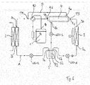
- the cycle system for heating and/or cooling comprises a main cycle A for circulating a refrigerant having a compressor 1 with compressor inlet 1a and outlet 1b, a condenser with condenser inlet 2a and outlet 2b, a first expansion valve LEV-A, a third expansion valve LEV-B, an evaporator 3 with evaporator inlet 3a and outlet 3b, a liquid receiver 5 with liquid receiver inlet 5a and outlet 5b, a second solenoid valve 9 and a four-way valve which are sequentially connected in a flow direction of the refrigerant flowing through the main circuit.
- a main cycle A for circulating a refrigerant having a compressor 1 with compressor inlet 1a and outlet 1b, a condenser with condenser inlet 2a and outlet 2b, a first expansion valve LEV-A, a third expansion valve LEV-B, an evaporator 3 with evaporator inlet 3a and outlet 3b, a liquid receiver 5 with liquid receiver
- the first solenoid valve 7 is used to open and close the feed line 6 as well as to control the flow rate of the second refrigerant part through the feed line 6, the second channel of the internal heat exchanger 4 and the discharge line 8.
- the second solenoid valve 9 is used to open and close the section of the main circuit A between connection points P3 and P4 as well as to control a flow of the refrigerant in this section of the main circuit A.
- the cooling is effected by the low-pressure cold gas second refrigerant part branched off at the evaporator outlet 3b and flowing through the second channel of the internal heat exchanger.
- the condensed first refrigerant part is expanded by expansion valve LEV-C and collected as low-pressure cold liquid refrigerant in the liquid receiver 5.
- the cold liquid refrigerant discharged from the liquid receiver 5 is further expanded by expansion valve LEV-A and enters the evaporator 3.
- the cold liquid refrigerant is evaporized and discharged as low-pressure cold gas refrigerant.
- the second refrigerant is branched off from the main circuit A to be circulated through the internal heat exchanger 4.
- connection point P4 the branched off second refrigerant part, which has been heated up due to the heat exchange with the first refrigerant part in the internal heat exchanger 4, is fed back into the main circuit A.
- the hot gas first refrigerant part is cooled down and condensed in the internal heat exchanger before being expanded in the expansion valve LEV-C to reduce its pressure from the discharge pressure of the compressor 1 to the pressure of the liquid receiver 5.
- the refrigerant which reaches the condenser 2 at a lower flow rate causes a reduction of heating capacity below the minimum capacity of the main circuit A, which is the cycle system without the bypass passage B. This enables the compressor 1 to run continuously without on-off cycling at low heat load.
- the hot gas first refrigerant part in the bypass passage B is condensed before merging with the refrigerant in the main circuit A.
- the condensed refrigerant is collected before fed into the evaporator 3. Due to connecting the bypass passage outlet with the liquid receiver 5 via the main circuit A, excess gas can be stored in the liquid receiver 5 even if the hot gas is not completely condensed. This prevents refrigerant dryness at evaporator inlet from being increased as occurs in the conventional bypass circuit in the prior art, and a reduction of heat transfer efficiency at evaporator 3 can be avoided. Furthermore, due to being heated by the bypassed hot gas first refrigerant part in internal heat exchanger 4, the temperature of the refrigerant coming from the evaporator outlet 3b is increased before reaching the compressor inlet 1a. This helps to increase a superheat degree at the compressor inlet 1a protecting compressor 1 from sucking refrigerant liquid.
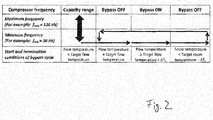
- Figure 2 shows a diagram with a sequence of starting and ending a bypass passage operation of the cycle system according to the first embodiment. It is known that supplied heat of cycle systems as in the present invention is controlled based on a temperature difference between a target flow temperature and a measured flow temperature.
- the target flow temperature T target_flow is also determined by an ambient temperature or a temperature difference between a set room temperature and a measured room temperature.
- a frequency range of the compressor is designed to avoid overloading, vibration etc. A maximum frequency is 120Hz and a minimum frequency is 30Hz, for example.
- the cycle system as shown in figure 1 is operated in whole compressor frequency range as long as the measured flow temperature is below a target flow temperature.
- the compressor frequency is fixed to the minimum frequency.
- the bypass passage is activated when the measured flow temperature rises above the target flow temperature + ⁇ T 1 and remains activated as long as the measured room temperature is higher than the target room temperature - ⁇ T 2 .
- the bypass passage is deactivated.
- FIG. 3 A specific example of a heating operation carried out by the cycle system according to the first embodiment with the bypass passage is shown in figure 3 .
- This control is based on the control strategy in which the flow temperature and the number of compressor restarts within a predefined interval (5 times per hour for example) are used as a trigger for the bypass passage activation.
- the bypass passage needs to be deactivated to return to normal heat load mode.
- LEV-C is controlled within a predefined control interval, which is every 1 minute for example.
- a ratio of increment and decrement of valve openings is also predefined, which is 10% for example.
- step ST8 it is checked, whether expansion valve LEV-C is completely closed. If Y, the system proceeds to step ST10. If N, the opening of LEV-C is decreased (step ST9) and the system proceeds to step ST10.
- step ST10 it is checked whether the room temperature is below the target room temperature - ⁇ T 3 . If N, the bypass passage remains activated and the system returns to step ST4. If Y, expansion valve LEV-C is closed deactivating the bypass passage and the system returns to the normal cycle operation.
- Figures 4 and 5 show a further preferred embodiment of a heating operation carried out by the cycle system of figure 1 .
- the control strategy is based on monitoring supplied heat from the cycle system. This supplied heat is compared with a minimum heat capacity of the cycle system derived from the performance map of the cycle system which is saved in a controller (not shown in figure 1 ) of the cycle system.
- the bypass cycle is started when the calculated average supplied heat within a predefined interval including ON/OFF cycle, 30 minutes for example, is below the minimum capacity of the cycle system at the same operating condition.
- LEV-C opening increases by reduction of supplied heat. For example, LEV-C opening increases by 10% when the supplied heat decreases by 10%.
- the performance map of the cycle system is built based on the cycle system capacity data at minimum frequency under different test conditions of water and ambient temperature.
- Q Capacity (kW)
- tw measured supply flow temperature
- ta measured ambient temperature
- t1,t2 reference data of ambient temperature
- w1, w2 reference data of supply flow temperature.
- FIG. 5 shows a flow diagram of a heating operation according to the second embodiment of the cycle system of the present invention with bypass passage.
- step ST1 normal cycle (i.e. with bypass passage deactivated)
- step ST2 the current supplied heat and minimum capacity are calculated.
- step ST3 it is checked, whether the supplied heat is 10% lower than the minimum capacity. If Y, the system proceeds to step ST4. If N, the system proceeds to step ST6.
- step ST4 it is checked, whether the expansion valve LEV-C is completely open.
- step ST6 it is checked, whether expansion valve LEV-C is completely closed. If N, the opening of LEV-C is decreased and the system returns to step ST2. If Y, bypass passage is deactivated and the system operates in normal cycle.
- Figure 6 shows a third embodiment of the cycle system for heating and/or cooling according to the present invention.
- the internal heat exchanger 4 is reversely connected to the main circuit A.
- the first internal heat exchanger inlet 4a and outlet 4b are connected to the second channel of the internal heat exchanger 4 and the second internal heat exchanger inlet 4c and outlet 4d are connected to the first channel of the internal heat exchanger 4.
- feed line 6, discharge line 8 and solenoid valves 7 and 9 have been omitted in the cycle system of embodiment 3.
- the liquid receiver 5 of the third embodiment has one more inlet 5c which enables to merge the refrigerant flows from the condenser 2 and the internal heat exchanger 4 inside the liquid receiver 5. This improves energy conservation within the cycle system.
- the cycle system according to the third embodiment is also configured to carry out the heating operation methods shown in figures 3 and 5 and the associated description.
Landscapes
- Engineering & Computer Science (AREA)
- Physics & Mathematics (AREA)
- Mechanical Engineering (AREA)
- Thermal Sciences (AREA)
- General Engineering & Computer Science (AREA)
- Air-Conditioning For Vehicles (AREA)
- Heat-Exchange Devices With Radiators And Conduit Assemblies (AREA)
Abstract
Description
- The present invention relates to a cycle system for heating and/or cooling and a heating and/or cooling operation method, in particular for partial and low heat load operation.
- A well known problem in cooling or heating operations is that an air-to-water heat pump becomes oversized when working at low heat load even though the compressor is running at its minimum frequency. This especially occurs in tight and well-insulated houses where heat pumps work at a very low water flow temperature. An air-to-water heat pump is generally controlled to keep a supply flow temperature at target value, and the supply flow temperature is controlled by changing the frequency of the compressor. If the heat load is lower than the minimum capacity with minimum frequency of the compressor, the heat pump stops running because the supply flow temperature rises above the threshold of detecting overheating and restarts after the supply flow temperature has fallen below the threshold of restarting. This results in the heat pump cycling on and off frequently, deteriorating efficiency, shortening system life and increasing electricity costs for end-users.
- For a load modulation of the heat pump, besides using a variable speed compressor, it is also common to use a hot-gas-bypass method to enable the system to run at a partial heat load. In this method, the hot-gas-bypass circuit is connected to the evaporator outlet to either control the evaporator cooling capacity (i.e. outlet bypass circuit) or defrost evaporator (as described in
US 6584794B2 ) or prevent freezing of the condenser in the reverse cycle-based defrost cycle (as described inWO 2011/092802 ). - In some cases of cooling application, a different configuration of a hot-gas-bypass is used to prevent the evaporator from freezing and going off on low pressure by connecting the hot gas-bypass circuit with the evaporator inlet (i.e. inlet bypass circuit). For heating application using air source heat pump, both inlet and outlet bypass circuits can be used.
- In particular, an inlet bypass circuit enables the heat pump to run at partial or low heat load by bypassing the refrigerant over the condenser during the normal heating operation. Here, an auxiliary expansion valve is arranged in the bypass circuit in order to expand hot-gas from the high pressure at compressor discharge to the low-pressure at evaporator inlet. This configuration is similar to the bypass-circuit described in
JP 4799252 JP 2005-300008 - A problem of the bypass circuit configurations in the prior art is that high-pressure refrigerant at vapour state (i.e. hot gas) is injected directly from the compressor discharge into the main circuit either after the main expansion valve (bypass-circuit in
JP 4799252 JP 2005-300008 - The problem to be solved by the present invention is therefore to provide a cycle system for heating and/or cooling and a heating and/or cooling operation method in which the heat transfer efficiency of the evaporator is not downgraded when a part of the refrigerant is bypassed under a low heat load condition wherein the heat load is less than the minimum capacity of the cycle system.
- The problem is solved by the cycle system for heating and/or cooling according to
claim 1 and the heating and/or cooling operation method according toclaim 10. Advantageous embodiments of the cycle system and the heating and/or cooling operation method are given in thedependent claims 2 to 9 and 11 to 15, respectively. - The cycle system for heating and/or cooling according to the present invention comprises a main circuit for circulating a refrigerant having a compressor, a condenser, a first expansion valve and an evaporator, which are sequentially connected in a flow direction of the refrigerant, and a bypass passage for bypassing a first refrigerant part around the condenser, wherein the bypass passage is connected to the main circuit in a first and a second connection point, wherein the first connection point is arranged between a compressor outlet and a condenser inlet and the second connection point is arranged between a condenser outlet and an evaporator inlet.
- The cycle system for heating and/or cooling is characterized in that the bypass passage includes an internal heat exchanger for exchanging heat between the first refrigerant part and a second refrigerant part, wherein the second refrigerant part is branched off from and fed back into the main circuit between the evaporator outlet and the compressor inlet, and a second expansion valve sequentially connected in the flow direction of the refrigerant, and in that the main circuit further comprises a liquid receiver, which is arranged in the second connection point and connected to the bypass passage or between the second connection point and the evaporator inlet.
- The cycle system for heating and/or cooling according to the present invention enables to condense hot gas in the bypass passage using an internal heat exchanger before mixing the condensed refrigerant of the main circuit at either the condenser outlet or liquid receiver. Due to bypassing a part of the refrigerant over the condenser, the heat capacity is decreased while the compressor is still running at its minimum frequency. This results in a supply flow temperature below the threshold for stopping the compressor.
- Furthermore, while the first expansion valve is the main expansion device of the main cycle, the second expansion valve functions as a bypass passage controlling device for modulating the mass flow rate of the first refrigerant part. In a further advantageous embodiment of the present invention, the first expansion valve is arranged between the second connection point and the evaporator inlet or between the condenser outlet and the second connection point.
- Moreover, the cycle system according to the present invention might be further modified such that the first expansion valve is arranged between the second connection point and the evaporator inlet, and the main circuit further comprises an additional third expansion valve which is arranged between the condenser outlet and the second connection point. In this case, the third expansion valve may be used to fine tune the flow rate of the refrigerant together with the second expansion valve.
- According to another preferred embodiment the internal heat exchanger comprises at least a first flow channel for conducting the first refrigerant part and a second flow channel for conducting the second refrigerant part.
- According to another preferred embodiment the internal heat exchanger is a double-pipe heat exchanger, a twisted-coil-type heat exchanger, a counter-flow heat exchanger, a parallel-flow heat exchanger and/or a heat exchanger comprising or consisting of micro-channels and/or micro-fins on both heat exchange surfaces.
- According to another preferred embodiment the internal heat exchanger comprises a feed line for feeding the second refrigerant part into the internal heat exchanger, wherein the feed line comprises a first solenoid valve to control a feed flow of the second refrigerant part.
- According to another preferred embodiment the internal heat exchanger comprises a feed line for feeding the second refrigerant part into the internal heat exchanger and a discharge line for feeding back the second refrigerant part into the main circuit, wherein the feed line and the discharge line are connected to the main circuit in a third and fourth connection point, respectively, and wherein the main circuit comprises a second solenoid valve arranged between the third and fourth connection point for opening and closing the section of the main circuit A between the third and fourth connection point and/or for controlling a flow of the refrigerant between the third and fourth connection point.
- According to another preferred embodiment the condenser is a refrigerant-water heat exchanger or a refrigerant-air heat exchanger and the evaporator is a refrigerant-air heat exchanger.
- According to another preferred embodiment the main circuit comprises a four-way valve arranged between the compressor outlet and the condenser inlet for switching the cycle system between heating operation and cooling operation.
- The invention also includes a heating and/or cooling operation method performed by the above-described cycle system for heating and/or cooling. The heating and/or cooling operation method is characterized in that the bypass passage is activated and/or deactivated when one or more predetermined conditions are met.
- According to a preferred embodiment the bypass passage is activated by opening the second expansion valve and deactivated by closing the second expansion valve. In particular, according to another preferred embodiment, the bypass passage is activated when a number of compressor restarts for a predetermined time interval is higher than a predetermined threshold number, and the bypass passage is deactivated when a room temperature is lower than a predetermined threshold room temperature.
- According to another preferred embodiment an opening of the second expansion valve is increased when the bypass passage is activated, the compressor runs at a predetermined minimum frequency and a supply flow temperature of the refrigerant is higher than a first predetermined threshold temperature, and the opening of the second expansion valve is decreased when the bypass passage is activated, the compressor runs at a predetermined minimum frequency and a supply flow temperature of the refrigerant is lower than a second predetermined threshold temperature.
- According to another preferred embodiment an average heat supply for a predetermined interval is calculated, a minimum capacity under an operated supply flow temperature and ambient temperature conditions is calculated, and the bypass passage is activated when the average heat supply is lower than the minimum capacity.
- According to another preferred embodiment an opening of the second expansion valve is increased by the same percentage as by which the average heat supply is lower than the minimum capacity.
- In the following, some preferred embodiments of the cycle system for heating and/or cooling as well as of the heating and/or cooling operation method according to the present invention are described in more detail on the basis of
figures 1 to 6 . The described features are not only conceivable in the combinations of the disclosed embodiments, but can be realized independently of the concrete embodiments in various other combinations. -
Figure 1 shows a first embodiment according to the invention of the cycle system for heating and/or cooling. -
Figure 2 shows a diagram with a sequence of starting and ending an operation of the bypass passage. -
Figure 3 shows a flow diagram of a heating operation method according to the first embodiment of the invention. -
Figure 4 shows a diagram with different heat capacities at minimum frequency for different test conditions. -
Figure 5 shows a flow diagram of a heating operation method according to a second embodiment of the invention. -
Figure 6 shows a third embodiment of the cycle system for heating and/or cooling according to the invention. - As shown in
figure 1 , the cycle system for heating and/or cooling according to a first embodiment of the invention comprises a main cycle A for circulating a refrigerant having acompressor 1 withcompressor inlet 1a and outlet 1b, a condenser with condenser inlet 2a and outlet 2b, a first expansion valve LEV-A, a third expansion valve LEV-B, anevaporator 3 withevaporator inlet 3a and outlet 3b, a liquid receiver 5 withliquid receiver inlet 5a and outlet 5b, asecond solenoid valve 9 and a four-way valve which are sequentially connected in a flow direction of the refrigerant flowing through the main circuit. - Furthermore, the cycle system comprises a bypass passage for bypassing a first refrigerant part over the
condenser 2. The bypass passage is connected to the main circuit via connection points P1 and P2. Connection point P1 is arranged between the compressor outlet 1b and the condenser inlet 2a. Connection point P2 is arranged between the third expansion valve LEV-B and theliquid receiver inlet 5a. The bypass passage B includes aninternal heat exchanger 4 and a second expansion valve LEV-C which are sequentially connected in the flow direction of the first refrigerant part. Theinternal heat exchanger 4 has at least two flow channels, wherein the first flow channel forms a section of the bypass passage B with first internalheat exchanger inlet 4a andfirst outlet 4b and conducts the first refrigerant part. The second channel extends from a second internalheat exchanger inlet 4c to a second internalheat exchanger outlet 4d and conducts a second refrigerant part which is branched off from and fed back into the main circuit A between the evaporator outlet 3b and thecompressor inlet 1a. The second internalheat exchanger inlet 4c is connected via a feed line 6 with the main circuit A in connection point P3. The second internalheat exchanger outlet 4d is connected via adischarge line 8 with the main circuit A in connection point P4. Connection point P3 is arranged between the evaporator outlet 3b and thecompressor inlet 1a. Connection point P4 is arranged between connection point P3 and thecompressor inlet 1a. The feed line 6 includes afirst solenoid valve 7. - In heating operation, the
condenser 2 is a water-refrigerant heat exchanger and functions as an indoor heater, whereas theevaporator 3 is an air-refrigerant heat exchanger functioning as a cooler. Moreover, theinternal heat exchanger 4 is a refrigerant-refrigerant heat exchanger, wherein heat is transferred from the bypassed first refrigerant part to the branched off second refrigerant part. In thisembodiment 1, theinternal heat exchanger 4 is preferably a counter-flow or parallel-flow heat exchanging device with hot-gas refrigerant flowing through the first channel and cold-gas or vapor refrigerant escaping from the evaporator outlet 3b flowing through the second channel. - The first expansion valve LEV-A is the main expansion valve of the main circuit A for expanding the refrigerant before entering the
evaporator 3. The second expansion valve LEV-C expands the first refrigerant part flowing trough the bypass passage and can be used to control the flow rate of the first refrigerant part. The third expansion valve LEV-B is used to fine tune the flow rates of the refrigerant flowing through the main circuit A and the bypass passage B. - The
first solenoid valve 7 is used to open and close the feed line 6 as well as to control the flow rate of the second refrigerant part through the feed line 6, the second channel of theinternal heat exchanger 4 and thedischarge line 8. Thesecond solenoid valve 9 is used to open and close the section of the main circuit A between connection points P3 and P4 as well as to control a flow of the refrigerant in this section of the main circuit A. - The four-
way valve 10 is used to switch between a heating operation and a cooling operation of the cycle system. The connection point P1 of the main circuit A and the bypass passage B can be either before or after the four-way valve 10 in the flow direction of the refrigerant. - The hot compressed refrigerant which is discharged at compressor outlet 1b passes the four-
way valve 10. At connection point P1 a first refrigerant part is branched off into the bypass passage B. In the main circuit A, the high-pressure hot gas refrigerant enters thecondenser 2 where it is cooled and condensed emitting heat to an indoor heater. The condensed refrigerant is expanded by expansion valve LEV-B and collected as low-pressure cold liquid refrigerant in the liquid receiver 5. The high-pressure hot gas first refrigerant part passes the first channel of theinternal heat exchanger 4 where it is cooled and condensed. The cooling is effected by the low-pressure cold gas second refrigerant part branched off at the evaporator outlet 3b and flowing through the second channel of the internal heat exchanger. The condensed first refrigerant part is expanded by expansion valve LEV-C and collected as low-pressure cold liquid refrigerant in the liquid receiver 5. The cold liquid refrigerant discharged from the liquid receiver 5 is further expanded by expansion valve LEV-A and enters theevaporator 3. In theevaporator 3, the cold liquid refrigerant is evaporized and discharged as low-pressure cold gas refrigerant. At connection point P3 the second refrigerant is branched off from the main circuit A to be circulated through theinternal heat exchanger 4. The remaining low-pressure cold gas refrigerant continues along the main circuit A to thecompressor inlet 1a. At connection point P4 the branched off second refrigerant part, which has been heated up due to the heat exchange with the first refrigerant part in theinternal heat exchanger 4, is fed back into the main circuit A. - Due to the heat exchange with the cold second refrigerant part, the hot gas first refrigerant part is cooled down and condensed in the internal heat exchanger before being expanded in the expansion valve LEV-C to reduce its pressure from the discharge pressure of the
compressor 1 to the pressure of the liquid receiver 5. By bypassing the first refrigerant part through the bypass passage B, the refrigerant which reaches thecondenser 2 at a lower flow rate causes a reduction of heating capacity below the minimum capacity of the main circuit A, which is the cycle system without the bypass passage B. This enables thecompressor 1 to run continuously without on-off cycling at low heat load. The hot gas first refrigerant part in the bypass passage B is condensed before merging with the refrigerant in the main circuit A. In the liquid receiver 5 the condensed refrigerant is collected before fed into theevaporator 3. Due to connecting the bypass passage outlet with the liquid receiver 5 via the main circuit A, excess gas can be stored in the liquid receiver 5 even if the hot gas is not completely condensed. This prevents refrigerant dryness at evaporator inlet from being increased as occurs in the conventional bypass circuit in the prior art, and a reduction of heat transfer efficiency atevaporator 3 can be avoided. Furthermore, due to being heated by the bypassed hot gas first refrigerant part ininternal heat exchanger 4, the temperature of the refrigerant coming from the evaporator outlet 3b is increased before reaching thecompressor inlet 1a. This helps to increase a superheat degree at thecompressor inlet 1a protecting compressor 1 from sucking refrigerant liquid. -
Figure 2 shows a diagram with a sequence of starting and ending a bypass passage operation of the cycle system according to the first embodiment. It is known that supplied heat of cycle systems as in the present invention is controlled based on a temperature difference between a target flow temperature and a measured flow temperature. The target flow temperature Ttarget_flow is also determined by an ambient temperature or a temperature difference between a set room temperature and a measured room temperature. A frequency range of the compressor is designed to avoid overloading, vibration etc. A maximum frequency is 120Hz and a minimum frequency is 30Hz, for example. In the present invention, a supply flow temperature at the minimum frequency Tfrequency_min is used as an input parameter to activate the bypass passage (Tfrequency_min = Ttarget_flow + ΔT1, ΔT1 is 1.5°C for example, smaller than the threshold of stopping the cycle system). The room temperature is used to terminate the bypass passage operation when heat load is required to be increased. The frequency is fixed at a minimum frequency during bypass passage activation. - As shown in
figure 2 , the cycle system as shown infigure 1 , for example, is operated in whole compressor frequency range as long as the measured flow temperature is below a target flow temperature. When the measured flow temperature equals the target flow temperature, the compressor frequency is fixed to the minimum frequency. The bypass passage is activated when the measured flow temperature rises above the target flow temperature + ΔT1 and remains activated as long as the measured room temperature is higher than the target room temperature - ΔT2. When the measured room temperature is equal to or lower than the target room temperature - ΔT2, the bypass passage is deactivated. - A specific example of a heating operation carried out by the cycle system according to the first embodiment with the bypass passage is shown in
figure 3 . This control is based on the control strategy in which the flow temperature and the number of compressor restarts within a predefined interval (5 times per hour for example) are used as a trigger for the bypass passage activation. When a room temperature drop is detected, which means that an increase of supplied heat is required, the bypass passage needs to be deactivated to return to normal heat load mode. LEV-C is controlled within a predefined control interval, which is every 1 minute for example. And a ratio of increment and decrement of valve openings is also predefined, which is 10% for example. - In the heating operation of
figure 3 , it is checked in step ST1, whether the compressor is running at a minimum frequency. If the answer is no (N), the cycle system remains in the normal cycle (i.e. without bypass passage). If the answer is yes (Y), it is checked in step ST2, whether the supply flow temperature is higher than the target flow temperature + ΔT1. If N, the system remains in the normal cycle. If Y, it is checked in ST3, whether the number of compressor restarts is above a threshold. If N, the system remains in the normal cycle. If Y, the bypass passage is activated and the system proceeds to a control loop including steps ST4 to ST10 for controlling the opening degree of the expansion valve LEV-C. In step ST4, it is checked, whether the supply flow temperature is lower than a target flow temperature - ΔT2. If N, the system proceeds to step ST5. If Y, the system proceeds to step ST8. In step ST5, it is checked whether the supply flow temperature is higher than the target flow temperature + ΔT1. If N, the system proceeds to step ST10. If Y, the system proceeds to step ST6. In step ST6, it is checked whether expansion valve LEV-C is completely open. If Y, the system proceeds to step ST10. If N, the opening of LEV-C is increased (step ST7) and the system proceeds to step ST10. - In step ST8, it is checked, whether expansion valve LEV-C is completely closed. If Y, the system proceeds to step ST10. If N, the opening of LEV-C is decreased (step ST9) and the system proceeds to step ST10.
- In step ST10, it is checked whether the room temperature is below the target room temperature - ΔT3. If N, the bypass passage remains activated and the system returns to step ST4. If Y, expansion valve LEV-C is closed deactivating the bypass passage and the system returns to the normal cycle operation.
-
Figures 4 and5 show a further preferred embodiment of a heating operation carried out by the cycle system offigure 1 . The control strategy is based on monitoring supplied heat from the cycle system. This supplied heat is compared with a minimum heat capacity of the cycle system derived from the performance map of the cycle system which is saved in a controller (not shown infigure 1 ) of the cycle system. The supplied heat is calculated with the following formula:
- Qsupply : Supplied heat (kW), ρwater: Density of water (kg/L),
- Cp,water : Specific heat (kJ/kgK), Fw: Water flow rate (L/s),
- Twater, supply : Supply flow temperature, Twater, return : Return flow temperature.
- The bypass cycle is started when the calculated average supplied heat within a predefined interval including ON/OFF cycle, 30 minutes for example, is below the minimum capacity of the cycle system at the same operating condition. LEV-C opening increases by reduction of supplied heat. For example, LEV-C opening increases by 10% when the supplied heat decreases by 10%. The performance map of the cycle system is built based on the cycle system capacity data at minimum frequency under different test conditions of water and ambient temperature. Minimum capacity under the operated condition is calculated using the formulas below:



- Where,
Q: Capacity (kW), tw: measured supply flow temperature, ta: measured ambient temperature t1,t2: reference data of ambient temperature, w1, w2: reference data of supply flow temperature. -
Figure 5 shows a flow diagram of a heating operation according to the second embodiment of the cycle system of the present invention with bypass passage. During normal cycle (i.e. with bypass passage deactivated), it is checked in step ST1, whether the compressor is running at minimum frequency. If the answer is no (N), the system remains in the normal cycle operation. If the answer is yes (Y), the bypass passage is activated and the system proceeds to step ST2. In step ST2, the current supplied heat and minimum capacity are calculated. After that, the system proceeds to step ST3. In step ST3, it is checked, whether the supplied heat is 10% lower than the minimum capacity. If Y, the system proceeds to step ST4. If N, the system proceeds to step ST6. In step ST4, it is checked, whether the expansion valve LEV-C is completely open. If Y, the system returns to step ST2. If N, the opening degree of LEV-C is increased by 10% and the system returns to step ST2. In step ST6, it is checked, whether expansion valve LEV-C is completely closed. If N, the opening of LEV-C is decreased and the system returns to step ST2. If Y, bypass passage is deactivated and the system operates in normal cycle. -
Figure 6 shows a third embodiment of the cycle system for heating and/or cooling according to the present invention. In the following, only the differences between the cycle system according to the first embodiment shown infigure 1 and the cycle system of the third embodiment are described. In contrast to the cycle system offigure 1 , in the cycle system offigure 3 theinternal heat exchanger 4 is reversely connected to the main circuit A. In the cycle system offigure 3 , the first internalheat exchanger inlet 4a andoutlet 4b are connected to the second channel of theinternal heat exchanger 4 and the second internalheat exchanger inlet 4c andoutlet 4d are connected to the first channel of theinternal heat exchanger 4. In addition, feed line 6,discharge line 8 andsolenoid valves embodiment 3. The reversed connection of theinternal heat exchanger 4 results in a reversed pressure level for theinternal heat exchanger 4. On the low-pressure side, which is connected to the evaporator outlet 3b, the flow rate of the refrigerant is increased compared to the cycle system of the first embodiment. The performance of theinternal heat exchanger 4 offigure 6 is changed due to the heat transfer coefficient changes. Moreover, theinternal heat exchanger 4 ofembodiment 3 can be more compact than inembodiment 1. - Another difference consists in that, in the cycle system of
figure 6 , the second connection point P2 is arranged within the liquid receiver 5. The liquid receiver 5 of the third embodiment has one more inlet 5c which enables to merge the refrigerant flows from thecondenser 2 and theinternal heat exchanger 4 inside the liquid receiver 5. This improves energy conservation within the cycle system. - The cycle system according to the third embodiment is also configured to carry out the heating operation methods shown in
figures 3 and5 and the associated description.
Claims (15)
- Cycle system for heating and/or cooling comprising
a main circuit for circulating a refrigerant having a compressor, a condenser, a first expansion valve and an evaporator, which are sequentially connected in a flow direction of the refrigerant, and
a bypass passage for bypassing a first refrigerant part around the condenser, wherein the bypass passage is connected to the main circuit in a first and a second connection point, wherein the first connection point is arranged between a compressor outlet and a condenser inlet and the second connection point is arranged between a condenser outlet and an evaporator inlet,
characterized in that
the bypass passage includes an internal heat exchanger for exchanging heat between the first refrigerant part and a second refrigerant part, wherein the second refrigerant part is branched off from and fed back into the main circuit between the evaporator outlet and the compressor inlet, and a second expansion valve sequentially connected in the flow direction of the refrigerant, and
the main circuit further comprises a liquid receiver, which is arranged in the second connection point and connected to the bypass passage or between the second connection point and the evaporator inlet. - Cycle system according to the preceding claim, wherein the first expansion valve is arranged between the second connection point and the evaporator inlet or between the condenser outlet and the second connection point.
- Cycle system according to claim 1, wherein the first expansion valve is arranged between the second connection point and the evaporator inlet, and the main circuit further comprises a third expansion valve arranged between the condenser outlet and the second connection point.
- Cycle system according to one of the preceding claims, wherein the internal heat exchanger comprises at least a first flow channel for conducting the first refrigerant part and a second flow channel for conducting the second refrigerant part.
- Cycle system according to one of the preceding claims, wherein the internal heat exchanger is a double-pipe heat exchanger, a twisted-coil-type heat exchanger, a counter-flow heat exchanger, a parallel-flow heat exchanger and/or a heat exchanger comprising or consisting of micro-channels and/or micro-fins on both heat exchange surfaces.
- Cycle system according to one of the preceding claims, wherein the internal heat exchanger comprises a feed line for feeding the second refrigerant part into the internal heat exchanger, wherein the feed line comprises a first solenoid valve to control a feed flow of the second refrigerant part.
- Cycle system according to one of the preceding claims, wherein the internal heat exchanger comprises a feed line for feeding the second refrigerant part into the internal heat exchanger and a discharge line for feeding back the second refrigerant part into the main circuit, wherein the feed line and the discharge line are connected to the main circuit in a third and fourth connection point, respectively, and wherein the main circuit comprises a second solenoid valve arranged between the third and fourth connection point for controlling a flow of the refrigerant between the third and fourth connection point.
- Cycle system according to one of the preceding claims, wherein the condenser is a refrigerant-water heat exchanger or a refrigerant-air heat exchanger and the evaporator is a refrigerant-air heat exchanger.
- Cycle system according to one of the preceding claims, wherein the main circuit comprises a four-way valve arranged between the compressor outlet and the condenser inlet for switching the cycle system between heating operation and cooling operation.
- Heating and/or cooling operation method performed by the cycle system according to one of the preceding claims, wherein the bypass passage is activated and/or deactivated when one or more predetermined conditions are met.
- Heating and/or cooling operation method according to the preceding claim, wherein the bypass passage is activated by opening the second expansion valve and deactivated by closing the second expansion valve.
- Heating operation method according to one of the two preceding claims, wherein
the bypass passage is activated when a number of compressor restarts for a predetermined time interval is higher than a predetermined threshold number, and wherein
the bypass passage is deactivated when a room temperature is lower than a predetermined threshold room temperature. - Heating operation method according to the preceding claim, wherein
an opening of the second expansion valve is increased when the bypass passage is activated, the compressor runs at a predetermined minimum frequency and a supply flow temperature of the refrigerant is higher than a first predetermined threshold temperature, and wherein
the opening of the second expansion valve is decreased when the bypass passage is activated, the compressor runs at a predetermined minimum frequency and a supply flow temperature of the refrigerant is lower than a second predetermined threshold temperature. - Heating operation according to claim 11, wherein
an average heat supply for a predetermined interval is calculated,
a minimum capacity under an operated supply flow temperature and ambient temperature conditions is calculated, and
the bypass passage is activated when the average heat supply is lower than the minimum capacity. - Heating operation method according to the preceding claim, wherein an opening of the second expansion valve is increased by the same percentage as by which the average heat supply is lower than the minimum capacity.
Priority Applications (2)
| Application Number | Priority Date | Filing Date | Title |
|---|---|---|---|
| EP17164213.5A EP3382300B1 (en) | 2017-03-31 | 2017-03-31 | Cycle system for heating and/or cooling and heating and/or cooling operation method |
| JP2018062104A JP2018173260A (en) | 2017-03-31 | 2018-03-28 | Circulation system for heating and/or cooling, and operation method for heating and/or cooling |
Applications Claiming Priority (1)
| Application Number | Priority Date | Filing Date | Title |
|---|---|---|---|
| EP17164213.5A EP3382300B1 (en) | 2017-03-31 | 2017-03-31 | Cycle system for heating and/or cooling and heating and/or cooling operation method |
Publications (2)
| Publication Number | Publication Date |
|---|---|
| EP3382300A1 true EP3382300A1 (en) | 2018-10-03 |
| EP3382300B1 EP3382300B1 (en) | 2019-11-13 |
Family
ID=58464401
Family Applications (1)
| Application Number | Title | Priority Date | Filing Date |
|---|---|---|---|
| EP17164213.5A Active EP3382300B1 (en) | 2017-03-31 | 2017-03-31 | Cycle system for heating and/or cooling and heating and/or cooling operation method |
Country Status (2)
| Country | Link |
|---|---|
| EP (1) | EP3382300B1 (en) |
| JP (1) | JP2018173260A (en) |
Cited By (3)
| Publication number | Priority date | Publication date | Assignee | Title |
|---|---|---|---|---|
| CN114111087A (en) * | 2020-08-26 | 2022-03-01 | 广东美的暖通设备有限公司 | Air conditioning system and control method thereof |
| CN114435060A (en) * | 2020-10-30 | 2022-05-06 | 上海汉钟精机股份有限公司 | Air conditioning system capable of efficiently heating at low temperature |
| US20230384010A1 (en) * | 2020-08-26 | 2023-11-30 | Gd Midea Heating & Ventilating Equipment Co., Ltd. | Air Conditioning System |
Families Citing this family (3)
| Publication number | Priority date | Publication date | Assignee | Title |
|---|---|---|---|---|
| JP7467827B2 (en) * | 2019-03-08 | 2024-04-16 | 株式会社富士通ゼネラル | Air conditioners |
| KR102049026B1 (en) * | 2019-04-12 | 2019-11-27 | 이항식 | High efficiency air-conditioner |
| KR102618118B1 (en) * | 2023-04-11 | 2023-12-27 | (주)하이세이브아시아 | Liquid refrigerant mild method for supplying low temperature refrigerant to the suction side of the refrigerant liquid pump that circulates the refrigerant in the refrigeration system under increased pressure |
Citations (7)
| Publication number | Priority date | Publication date | Assignee | Title |
|---|---|---|---|---|
| WO2002023105A1 (en) * | 2000-09-15 | 2002-03-21 | Mile High Equipment Company | Quiet ice making apparatus |
| US6584794B2 (en) | 2001-07-06 | 2003-07-01 | Denso Corporation | Ejector cycle system |
| US20050081545A1 (en) * | 2000-09-15 | 2005-04-21 | Scotsman Ice Systems And Mile High Equipment Company | Integrated ice and beverage dispenser |
| JP2005300008A (en) | 2004-04-12 | 2005-10-27 | Matsushita Electric Ind Co Ltd | Heat pump water heater |
| EP2224191A2 (en) * | 2009-02-25 | 2010-09-01 | LG Electronics Inc. | Air conditioner and method of controlling the same |
| WO2011092802A1 (en) | 2010-01-26 | 2011-08-04 | 三菱電機株式会社 | Heat pump device and refrigerant bypass method |
| JP4799252B2 (en) | 2006-04-06 | 2011-10-26 | サンデン株式会社 | Air conditioner |
-
2017
- 2017-03-31 EP EP17164213.5A patent/EP3382300B1/en active Active
-
2018
- 2018-03-28 JP JP2018062104A patent/JP2018173260A/en active Pending
Patent Citations (8)
| Publication number | Priority date | Publication date | Assignee | Title |
|---|---|---|---|---|
| WO2002023105A1 (en) * | 2000-09-15 | 2002-03-21 | Mile High Equipment Company | Quiet ice making apparatus |
| US20050081545A1 (en) * | 2000-09-15 | 2005-04-21 | Scotsman Ice Systems And Mile High Equipment Company | Integrated ice and beverage dispenser |
| US6584794B2 (en) | 2001-07-06 | 2003-07-01 | Denso Corporation | Ejector cycle system |
| JP2005300008A (en) | 2004-04-12 | 2005-10-27 | Matsushita Electric Ind Co Ltd | Heat pump water heater |
| JP4799252B2 (en) | 2006-04-06 | 2011-10-26 | サンデン株式会社 | Air conditioner |
| EP2224191A2 (en) * | 2009-02-25 | 2010-09-01 | LG Electronics Inc. | Air conditioner and method of controlling the same |
| WO2011092802A1 (en) | 2010-01-26 | 2011-08-04 | 三菱電機株式会社 | Heat pump device and refrigerant bypass method |
| EP2530410A1 (en) * | 2010-01-26 | 2012-12-05 | Mitsubishi Electric Corporation | Heat pump device and refrigerant bypass method |
Cited By (5)
| Publication number | Priority date | Publication date | Assignee | Title |
|---|---|---|---|---|
| CN114111087A (en) * | 2020-08-26 | 2022-03-01 | 广东美的暖通设备有限公司 | Air conditioning system and control method thereof |
| CN114111087B (en) * | 2020-08-26 | 2023-01-31 | 广东美的暖通设备有限公司 | Air conditioning system and its control method |
| US20230384010A1 (en) * | 2020-08-26 | 2023-11-30 | Gd Midea Heating & Ventilating Equipment Co., Ltd. | Air Conditioning System |
| US12540766B2 (en) * | 2020-08-26 | 2026-02-03 | Gd Midea Heating & Ventilating Equipment Co., Ltd. | Air conditioning system |
| CN114435060A (en) * | 2020-10-30 | 2022-05-06 | 上海汉钟精机股份有限公司 | Air conditioning system capable of efficiently heating at low temperature |
Also Published As
| Publication number | Publication date |
|---|---|
| EP3382300B1 (en) | 2019-11-13 |
| JP2018173260A (en) | 2018-11-08 |
Similar Documents
| Publication | Publication Date | Title |
|---|---|---|
| EP3382300B1 (en) | Cycle system for heating and/or cooling and heating and/or cooling operation method | |
| EP3062031B1 (en) | Air conditioner | |
| EP2995885B1 (en) | Binary refrigeration device | |
| EP1967801B1 (en) | Hot water system | |
| EP2535674B1 (en) | Refrigeration cycle apparatus and hydronic heater having the refrigeration cycle apparatus | |
| EP2924375B1 (en) | Refrigeration cycle device and hot water generation device provided therewith | |
| EP2765370A1 (en) | Refrigeration cycle apparatus and hot water generator provided with the same | |
| CN102734969B (en) | The hot-water central heating system of freezing cycle device and this freezing cycle device of outfit | |
| EP3040643B1 (en) | Heat pump system, and heat pump water heater | |
| EP2522934A2 (en) | Heat storing apparatus having cascade cycle and control process of the same | |
| JP6129520B2 (en) | Multi-type air conditioner and control method of multi-type air conditioner | |
| JP5653451B2 (en) | Heat pump type water heater | |
| EP2320164A2 (en) | Refrigeration cycle apparatus and hot water heater | |
| CN102419024A (en) | Refrigeration cycle device and hot water heating device | |
| EP3267130B1 (en) | Refrigeration cycle device | |
| EP3211350B1 (en) | Refrigeration cycle device, and hot water heating device provided with the same | |
| JP2023509017A (en) | air conditioner | |
| US11391497B2 (en) | Refrigeration apparatus and temperature control apparatus | |
| EP3789695A1 (en) | A hvac system | |
| KR20190055961A (en) | Air conditioner and the method controlling the same | |
| EP2918921B1 (en) | Hot water generator | |
| EP3220078A1 (en) | Refrigeration cycle device and hot water heating device provided with the same | |
| EP2918947B1 (en) | Air conditioner | |
| US9261297B2 (en) | Cooling device | |
| JP2013217602A (en) | Heat source device, refrigeration air conditioner, and control device |
Legal Events
| Date | Code | Title | Description |
|---|---|---|---|
| PUAI | Public reference made under article 153(3) epc to a published international application that has entered the european phase |
Free format text: ORIGINAL CODE: 0009012 |
|
| STAA | Information on the status of an ep patent application or granted ep patent |
Free format text: STATUS: THE APPLICATION HAS BEEN PUBLISHED |
|
| AK | Designated contracting states |
Kind code of ref document: A1 Designated state(s): AL AT BE BG CH CY CZ DE DK EE ES FI FR GB GR HR HU IE IS IT LI LT LU LV MC MK MT NL NO PL PT RO RS SE SI SK SM TR |
|
| AX | Request for extension of the european patent |
Extension state: BA ME |
|
| STAA | Information on the status of an ep patent application or granted ep patent |
Free format text: STATUS: REQUEST FOR EXAMINATION WAS MADE |
|
| 17P | Request for examination filed |
Effective date: 20190329 |
|
| RBV | Designated contracting states (corrected) |
Designated state(s): AL AT BE BG CH CY CZ DE DK EE ES FI FR GB GR HR HU IE IS IT LI LT LU LV MC MK MT NL NO PL PT RO RS SE SI SK SM TR |
|
| GRAP | Despatch of communication of intention to grant a patent |
Free format text: ORIGINAL CODE: EPIDOSNIGR1 |
|
| STAA | Information on the status of an ep patent application or granted ep patent |
Free format text: STATUS: GRANT OF PATENT IS INTENDED |
|
| INTG | Intention to grant announced |
Effective date: 20190607 |
|
| GRAS | Grant fee paid |
Free format text: ORIGINAL CODE: EPIDOSNIGR3 |
|
| GRAA | (expected) grant |
Free format text: ORIGINAL CODE: 0009210 |
|
| STAA | Information on the status of an ep patent application or granted ep patent |
Free format text: STATUS: THE PATENT HAS BEEN GRANTED |
|
| AK | Designated contracting states |
Kind code of ref document: B1 Designated state(s): AL AT BE BG CH CY CZ DE DK EE ES FI FR GB GR HR HU IE IS IT LI LT LU LV MC MK MT NL NO PL PT RO RS SE SI SK SM TR |
|
| REG | Reference to a national code |
Ref country code: CH Ref legal event code: EP Ref country code: AT Ref legal event code: REF Ref document number: 1202079 Country of ref document: AT Kind code of ref document: T Effective date: 20191115 |
|
| REG | Reference to a national code |
Ref country code: DE Ref legal event code: R096 Ref document number: 602017008572 Country of ref document: DE |
|
| REG | Reference to a national code |
Ref country code: IE Ref legal event code: FG4D |
|
| REG | Reference to a national code |
Ref country code: NL Ref legal event code: MP Effective date: 20191113 |
|
| REG | Reference to a national code |
Ref country code: LT Ref legal event code: MG4D |
|
| PG25 | Lapsed in a contracting state [announced via postgrant information from national office to epo] |
Ref country code: SE Free format text: LAPSE BECAUSE OF FAILURE TO SUBMIT A TRANSLATION OF THE DESCRIPTION OR TO PAY THE FEE WITHIN THE PRESCRIBED TIME-LIMIT Effective date: 20191113 Ref country code: LV Free format text: LAPSE BECAUSE OF FAILURE TO SUBMIT A TRANSLATION OF THE DESCRIPTION OR TO PAY THE FEE WITHIN THE PRESCRIBED TIME-LIMIT Effective date: 20191113 Ref country code: PL Free format text: LAPSE BECAUSE OF FAILURE TO SUBMIT A TRANSLATION OF THE DESCRIPTION OR TO PAY THE FEE WITHIN THE PRESCRIBED TIME-LIMIT Effective date: 20191113 Ref country code: GR Free format text: LAPSE BECAUSE OF FAILURE TO SUBMIT A TRANSLATION OF THE DESCRIPTION OR TO PAY THE FEE WITHIN THE PRESCRIBED TIME-LIMIT Effective date: 20200214 Ref country code: NO Free format text: LAPSE BECAUSE OF FAILURE TO SUBMIT A TRANSLATION OF THE DESCRIPTION OR TO PAY THE FEE WITHIN THE PRESCRIBED TIME-LIMIT Effective date: 20200213 Ref country code: PT Free format text: LAPSE BECAUSE OF FAILURE TO SUBMIT A TRANSLATION OF THE DESCRIPTION OR TO PAY THE FEE WITHIN THE PRESCRIBED TIME-LIMIT Effective date: 20200313 Ref country code: BG Free format text: LAPSE BECAUSE OF FAILURE TO SUBMIT A TRANSLATION OF THE DESCRIPTION OR TO PAY THE FEE WITHIN THE PRESCRIBED TIME-LIMIT Effective date: 20200213 Ref country code: LT Free format text: LAPSE BECAUSE OF FAILURE TO SUBMIT A TRANSLATION OF THE DESCRIPTION OR TO PAY THE FEE WITHIN THE PRESCRIBED TIME-LIMIT Effective date: 20191113 Ref country code: FI Free format text: LAPSE BECAUSE OF FAILURE TO SUBMIT A TRANSLATION OF THE DESCRIPTION OR TO PAY THE FEE WITHIN THE PRESCRIBED TIME-LIMIT Effective date: 20191113 Ref country code: NL Free format text: LAPSE BECAUSE OF FAILURE TO SUBMIT A TRANSLATION OF THE DESCRIPTION OR TO PAY THE FEE WITHIN THE PRESCRIBED TIME-LIMIT Effective date: 20191113 |
|
| PG25 | Lapsed in a contracting state [announced via postgrant information from national office to epo] |
Ref country code: RS Free format text: LAPSE BECAUSE OF FAILURE TO SUBMIT A TRANSLATION OF THE DESCRIPTION OR TO PAY THE FEE WITHIN THE PRESCRIBED TIME-LIMIT Effective date: 20191113 Ref country code: IS Free format text: LAPSE BECAUSE OF FAILURE TO SUBMIT A TRANSLATION OF THE DESCRIPTION OR TO PAY THE FEE WITHIN THE PRESCRIBED TIME-LIMIT Effective date: 20200313 Ref country code: HR Free format text: LAPSE BECAUSE OF FAILURE TO SUBMIT A TRANSLATION OF THE DESCRIPTION OR TO PAY THE FEE WITHIN THE PRESCRIBED TIME-LIMIT Effective date: 20191113 |
|
| PG25 | Lapsed in a contracting state [announced via postgrant information from national office to epo] |
Ref country code: AL Free format text: LAPSE BECAUSE OF FAILURE TO SUBMIT A TRANSLATION OF THE DESCRIPTION OR TO PAY THE FEE WITHIN THE PRESCRIBED TIME-LIMIT Effective date: 20191113 |
|
| PG25 | Lapsed in a contracting state [announced via postgrant information from national office to epo] |
Ref country code: RO Free format text: LAPSE BECAUSE OF FAILURE TO SUBMIT A TRANSLATION OF THE DESCRIPTION OR TO PAY THE FEE WITHIN THE PRESCRIBED TIME-LIMIT Effective date: 20191113 Ref country code: EE Free format text: LAPSE BECAUSE OF FAILURE TO SUBMIT A TRANSLATION OF THE DESCRIPTION OR TO PAY THE FEE WITHIN THE PRESCRIBED TIME-LIMIT Effective date: 20191113 Ref country code: DK Free format text: LAPSE BECAUSE OF FAILURE TO SUBMIT A TRANSLATION OF THE DESCRIPTION OR TO PAY THE FEE WITHIN THE PRESCRIBED TIME-LIMIT Effective date: 20191113 Ref country code: ES Free format text: LAPSE BECAUSE OF FAILURE TO SUBMIT A TRANSLATION OF THE DESCRIPTION OR TO PAY THE FEE WITHIN THE PRESCRIBED TIME-LIMIT Effective date: 20191113 Ref country code: CZ Free format text: LAPSE BECAUSE OF FAILURE TO SUBMIT A TRANSLATION OF THE DESCRIPTION OR TO PAY THE FEE WITHIN THE PRESCRIBED TIME-LIMIT Effective date: 20191113 |
|
| REG | Reference to a national code |
Ref country code: DE Ref legal event code: R097 Ref document number: 602017008572 Country of ref document: DE |
|
| REG | Reference to a national code |
Ref country code: AT Ref legal event code: MK05 Ref document number: 1202079 Country of ref document: AT Kind code of ref document: T Effective date: 20191113 |
|
| PG25 | Lapsed in a contracting state [announced via postgrant information from national office to epo] |
Ref country code: SM Free format text: LAPSE BECAUSE OF FAILURE TO SUBMIT A TRANSLATION OF THE DESCRIPTION OR TO PAY THE FEE WITHIN THE PRESCRIBED TIME-LIMIT Effective date: 20191113 Ref country code: SK Free format text: LAPSE BECAUSE OF FAILURE TO SUBMIT A TRANSLATION OF THE DESCRIPTION OR TO PAY THE FEE WITHIN THE PRESCRIBED TIME-LIMIT Effective date: 20191113 |
|
| PLBE | No opposition filed within time limit |
Free format text: ORIGINAL CODE: 0009261 |
|
| STAA | Information on the status of an ep patent application or granted ep patent |
Free format text: STATUS: NO OPPOSITION FILED WITHIN TIME LIMIT |
|
| 26N | No opposition filed |
Effective date: 20200814 |
|
| PG25 | Lapsed in a contracting state [announced via postgrant information from national office to epo] |
Ref country code: MC Free format text: LAPSE BECAUSE OF FAILURE TO SUBMIT A TRANSLATION OF THE DESCRIPTION OR TO PAY THE FEE WITHIN THE PRESCRIBED TIME-LIMIT Effective date: 20191113 |
|
| REG | Reference to a national code |
Ref country code: CH Ref legal event code: PL |
|
| PG25 | Lapsed in a contracting state [announced via postgrant information from national office to epo] |
Ref country code: SI Free format text: LAPSE BECAUSE OF FAILURE TO SUBMIT A TRANSLATION OF THE DESCRIPTION OR TO PAY THE FEE WITHIN THE PRESCRIBED TIME-LIMIT Effective date: 20191113 Ref country code: AT Free format text: LAPSE BECAUSE OF FAILURE TO SUBMIT A TRANSLATION OF THE DESCRIPTION OR TO PAY THE FEE WITHIN THE PRESCRIBED TIME-LIMIT Effective date: 20191113 |
|
| REG | Reference to a national code |
Ref country code: BE Ref legal event code: MM Effective date: 20200331 |
|
| PG25 | Lapsed in a contracting state [announced via postgrant information from national office to epo] |
Ref country code: LU Free format text: LAPSE BECAUSE OF NON-PAYMENT OF DUE FEES Effective date: 20200331 |
|
| PG25 | Lapsed in a contracting state [announced via postgrant information from national office to epo] |
Ref country code: LI Free format text: LAPSE BECAUSE OF NON-PAYMENT OF DUE FEES Effective date: 20200331 Ref country code: IT Free format text: LAPSE BECAUSE OF FAILURE TO SUBMIT A TRANSLATION OF THE DESCRIPTION OR TO PAY THE FEE WITHIN THE PRESCRIBED TIME-LIMIT Effective date: 20191113 Ref country code: IE Free format text: LAPSE BECAUSE OF NON-PAYMENT OF DUE FEES Effective date: 20200331 Ref country code: CH Free format text: LAPSE BECAUSE OF NON-PAYMENT OF DUE FEES Effective date: 20200331 |
|
| PG25 | Lapsed in a contracting state [announced via postgrant information from national office to epo] |
Ref country code: BE Free format text: LAPSE BECAUSE OF NON-PAYMENT OF DUE FEES Effective date: 20200331 |
|
| PG25 | Lapsed in a contracting state [announced via postgrant information from national office to epo] |
Ref country code: TR Free format text: LAPSE BECAUSE OF FAILURE TO SUBMIT A TRANSLATION OF THE DESCRIPTION OR TO PAY THE FEE WITHIN THE PRESCRIBED TIME-LIMIT Effective date: 20191113 Ref country code: MT Free format text: LAPSE BECAUSE OF FAILURE TO SUBMIT A TRANSLATION OF THE DESCRIPTION OR TO PAY THE FEE WITHIN THE PRESCRIBED TIME-LIMIT Effective date: 20191113 Ref country code: CY Free format text: LAPSE BECAUSE OF FAILURE TO SUBMIT A TRANSLATION OF THE DESCRIPTION OR TO PAY THE FEE WITHIN THE PRESCRIBED TIME-LIMIT Effective date: 20191113 |
|
| PG25 | Lapsed in a contracting state [announced via postgrant information from national office to epo] |
Ref country code: MK Free format text: LAPSE BECAUSE OF FAILURE TO SUBMIT A TRANSLATION OF THE DESCRIPTION OR TO PAY THE FEE WITHIN THE PRESCRIBED TIME-LIMIT Effective date: 20191113 |
|
| P01 | Opt-out of the competence of the unified patent court (upc) registered |
Effective date: 20230512 |
|
| PGFP | Annual fee paid to national office [announced via postgrant information from national office to epo] |
Ref country code: GB Payment date: 20260319 Year of fee payment: 10 |
|
| PGFP | Annual fee paid to national office [announced via postgrant information from national office to epo] |
Ref country code: DE Payment date: 20260320 Year of fee payment: 10 |
|
| PGFP | Annual fee paid to national office [announced via postgrant information from national office to epo] |
Ref country code: FR Payment date: 20260323 Year of fee payment: 10 |