EP3382292A1 - Heating system and heating method - Google Patents
Heating system and heating method Download PDFInfo
- Publication number
- EP3382292A1 EP3382292A1 EP17164194.7A EP17164194A EP3382292A1 EP 3382292 A1 EP3382292 A1 EP 3382292A1 EP 17164194 A EP17164194 A EP 17164194A EP 3382292 A1 EP3382292 A1 EP 3382292A1
- Authority
- EP
- European Patent Office
- Prior art keywords
- heat
- pcm
- space
- state
- heating system
- Prior art date
- Legal status (The legal status is an assumption and is not a legal conclusion. Google has not performed a legal analysis and makes no representation as to the accuracy of the status listed.)
- Granted
Links
Images






Classifications
-
- F—MECHANICAL ENGINEERING; LIGHTING; HEATING; WEAPONS; BLASTING
- F24—HEATING; RANGES; VENTILATING
- F24D—DOMESTIC- OR SPACE-HEATING SYSTEMS, e.g. CENTRAL HEATING SYSTEMS; DOMESTIC HOT-WATER SUPPLY SYSTEMS; ELEMENTS OR COMPONENTS THEREFOR
- F24D11/00—Central heating systems using heat accumulated in storage masses
- F24D11/02—Central heating systems using heat accumulated in storage masses using heat pumps
- F24D11/0214—Central heating systems using heat accumulated in storage masses using heat pumps water heating system
-
- F—MECHANICAL ENGINEERING; LIGHTING; HEATING; WEAPONS; BLASTING
- F28—HEAT EXCHANGE IN GENERAL
- F28D—HEAT-EXCHANGE APPARATUS, NOT PROVIDED FOR IN ANOTHER SUBCLASS, IN WHICH THE HEAT-EXCHANGE MEDIA DO NOT COME INTO DIRECT CONTACT
- F28D1/00—Heat-exchange apparatus having stationary conduit assemblies for one heat-exchange medium only, the media being in contact with different sides of the conduit wall, in which the other heat-exchange medium is a large body of fluid, e.g. domestic or motor car radiators
- F28D1/02—Heat-exchange apparatus having stationary conduit assemblies for one heat-exchange medium only, the media being in contact with different sides of the conduit wall, in which the other heat-exchange medium is a large body of fluid, e.g. domestic or motor car radiators with heat-exchange conduits immersed in the body of fluid
- F28D1/0233—Heat-exchange apparatus having stationary conduit assemblies for one heat-exchange medium only, the media being in contact with different sides of the conduit wall, in which the other heat-exchange medium is a large body of fluid, e.g. domestic or motor car radiators with heat-exchange conduits immersed in the body of fluid with air flow channels
- F28D1/024—Heat-exchange apparatus having stationary conduit assemblies for one heat-exchange medium only, the media being in contact with different sides of the conduit wall, in which the other heat-exchange medium is a large body of fluid, e.g. domestic or motor car radiators with heat-exchange conduits immersed in the body of fluid with air flow channels with an air driving element
-
- F—MECHANICAL ENGINEERING; LIGHTING; HEATING; WEAPONS; BLASTING
- F28—HEAT EXCHANGE IN GENERAL
- F28D—HEAT-EXCHANGE APPARATUS, NOT PROVIDED FOR IN ANOTHER SUBCLASS, IN WHICH THE HEAT-EXCHANGE MEDIA DO NOT COME INTO DIRECT CONTACT
- F28D20/00—Heat storage plants or apparatus in general; Regenerative heat-exchange apparatus not covered by groups F28D17/00 or F28D19/00
- F28D20/0034—Heat storage plants or apparatus in general; Regenerative heat-exchange apparatus not covered by groups F28D17/00 or F28D19/00 using liquid heat storage material
-
- F—MECHANICAL ENGINEERING; LIGHTING; HEATING; WEAPONS; BLASTING
- F28—HEAT EXCHANGE IN GENERAL
- F28D—HEAT-EXCHANGE APPARATUS, NOT PROVIDED FOR IN ANOTHER SUBCLASS, IN WHICH THE HEAT-EXCHANGE MEDIA DO NOT COME INTO DIRECT CONTACT
- F28D20/00—Heat storage plants or apparatus in general; Regenerative heat-exchange apparatus not covered by groups F28D17/00 or F28D19/00
- F28D20/02—Heat storage plants or apparatus in general; Regenerative heat-exchange apparatus not covered by groups F28D17/00 or F28D19/00 using latent heat
- F28D20/021—Heat storage plants or apparatus in general; Regenerative heat-exchange apparatus not covered by groups F28D17/00 or F28D19/00 using latent heat the latent heat storage material and the heat-exchanging means being enclosed in one container
-
- F—MECHANICAL ENGINEERING; LIGHTING; HEATING; WEAPONS; BLASTING
- F24—HEATING; RANGES; VENTILATING
- F24D—DOMESTIC- OR SPACE-HEATING SYSTEMS, e.g. CENTRAL HEATING SYSTEMS; DOMESTIC HOT-WATER SUPPLY SYSTEMS; ELEMENTS OR COMPONENTS THEREFOR
- F24D2220/00—Components of central heating installations excluding heat sources
- F24D2220/10—Heat storage materials, e.g. phase change materials or static water enclosed in a space
-
- F—MECHANICAL ENGINEERING; LIGHTING; HEATING; WEAPONS; BLASTING
- F24—HEATING; RANGES; VENTILATING
- F24D—DOMESTIC- OR SPACE-HEATING SYSTEMS, e.g. CENTRAL HEATING SYSTEMS; DOMESTIC HOT-WATER SUPPLY SYSTEMS; ELEMENTS OR COMPONENTS THEREFOR
- F24D2220/00—Components of central heating installations excluding heat sources
- F24D2220/20—Heat consumers
- F24D2220/2009—Radiators
- F24D2220/2063—Central heating radiators having heat storage material incorporated
-
- F—MECHANICAL ENGINEERING; LIGHTING; HEATING; WEAPONS; BLASTING
- F24—HEATING; RANGES; VENTILATING
- F24F—AIR-CONDITIONING; AIR-HUMIDIFICATION; VENTILATION; USE OF AIR CURRENTS FOR SCREENING
- F24F5/00—Air-conditioning systems or apparatus not covered by F24F1/00 or F24F3/00, e.g. using solar heat or combined with household units such as an oven or water heater
- F24F5/0007—Air-conditioning systems or apparatus not covered by F24F1/00 or F24F3/00, e.g. using solar heat or combined with household units such as an oven or water heater cooling apparatus specially adapted for use in air-conditioning
- F24F5/0017—Air-conditioning systems or apparatus not covered by F24F1/00 or F24F3/00, e.g. using solar heat or combined with household units such as an oven or water heater cooling apparatus specially adapted for use in air-conditioning using cold storage bodies, e.g. ice
- F24F5/0021—Air-conditioning systems or apparatus not covered by F24F1/00 or F24F3/00, e.g. using solar heat or combined with household units such as an oven or water heater cooling apparatus specially adapted for use in air-conditioning using cold storage bodies, e.g. ice using phase change material [PCM] for storage
-
- Y—GENERAL TAGGING OF NEW TECHNOLOGICAL DEVELOPMENTS; GENERAL TAGGING OF CROSS-SECTIONAL TECHNOLOGIES SPANNING OVER SEVERAL SECTIONS OF THE IPC; TECHNICAL SUBJECTS COVERED BY FORMER USPC CROSS-REFERENCE ART COLLECTIONS [XRACs] AND DIGESTS
- Y02—TECHNOLOGIES OR APPLICATIONS FOR MITIGATION OR ADAPTATION AGAINST CLIMATE CHANGE
- Y02E—REDUCTION OF GREENHOUSE GAS [GHG] EMISSIONS, RELATED TO ENERGY GENERATION, TRANSMISSION OR DISTRIBUTION
- Y02E60/00—Enabling technologies; Technologies with a potential or indirect contribution to GHG emissions mitigation
- Y02E60/14—Thermal energy storage
Definitions
- the present invention relates to a heating system and a heating method.
- a basic idea of the present invention is to provide a means of storing excess heat for use at a later stage (and/or at a later time), wherein this means of storing excess heat comprises a phase change material, hereinafter abbreviated as PCM. It is also a basic idea of the present invention to provide a control for different states for the PCM.
- PCM phase change material
- a heating system according to the invention is described in claim 1.
- part of the heat coming from the heat source can be conveyed to the first space in order to increase the temperature therein, whereas already then another part of the heat coming from the heat source can be fed concurrently to the PCM to be stored in the latter.
- Between means that a change between states can be performed in both directions, for example from the emission state to the feed state and vice versa.
- the heat-transfer-medium can be water.
- the meaning of heat-transfer-medium/air (especially: water/air) heat exchanger is that heat can be transferred from a heat-transfer-medium (especially: water) to air and vice versa.
- the meaning of heat-transfer-medium/PCM (especially: water/PCM) heat exchanger is that heat can be transferred from a heat-transfer-medium (especially: water) to a PCM and vice versa.
- the heat emitting mechanism (that is, the heat-transfer-medium/air heat exchanger thereof and/or the heat storage and release mechanism thereof) can be adapted to emit heat into the first space.
- the first space is preferably a (first) room inside a building, inside which room preferably not only the heat storage and release mechanism, but also the complete heating mechanism (that is, the heat-transfer-medium/air heat exchanger as well as the heat storage and release mechanism) is located or arranged.
- the controlling of the heating system may be realized in computer implemented form and/or based on a central control unit of the heating system.
- This central control unit may be a computer or a microcontroller having a memory (adapted to store adequate control programs) and a microprocessor.
- controlling means regulating.
- the controlling/regulating of the heating system, especially of the heat storage and release mechanism thereof may be realized as a switching of the heat storage and release mechanism in between said (at least) three states (that is, the feed state, the emission state and the transport state), that is from an arbitrary one of these states into another arbitrary one of these states.
- the aim of the features described in this claim is to avoid that the target temperature becomes too high in the first space being the target.
- the heat-transfer-medium line can be a water-line in case of water being the heat-transfer-medium.
- the heat-transfer-medium is water.
- a heating method according to the invention is described in claim 16.
- empty spaces within heat emitters can be filled with a phase change material (PCM).
- PCM phase change material
- This phase change material in effect provides a heat storage medium thereby allowing for prolonged heating but with shorter heating and cooling operation cycles of the heat source.
- the PCM can be regulated to transport heat to a space adapted to store heat, that is a (central) thermal store, or elsewhere to prevent further release of heat into a space (first space) in which the target temperature has already been achieved; thereby minimizing waste of heat and of energy, respectively.
- a hot/cold water circuit, a heat exchanger, and a fan can be combined in order to supply heat and a thermal storage unit which can be composed of a PCM and a heat exchanger can be installed inside the chassis of a heat emitter.
- the thermal storage unit inside the chassis can supply heat to a room by transferring heat to air by an air flow provided by a fan.
- the PCM can be encapsulated and fitted in the empty space found within the heat emitter.
- the design and size of encapsulated material will be determined by the heat emitter in use.
- the PCM in this case can be an encapsulated paraffin or a salt hydrate with a melting temperature between 30°C and 40°C.
- a target room temperature (hereinafter abbreviated as T n ) can be set so as to be achieved by transfer of warm air from the heat emitter to the space/room in question.
- This target temperature is often surpassed (T room > T n ), meaning that excess heat enters the room/space to be heated.
- this excess heat can be diverted to the PCM for storage thereof, for example via operation of proportional valves, whereby an amount of water flowing in the emitter circuit is reduced and an amount of water flowing to the PCM is increased.
- the proportion of diversion can be based on sensing of the temperature maintained in the space/room to be heated in the first instance.
- the heat pump can go off.
- the water can be pumped to a second emitter in a second room/space.
- the second room is heated and when the target temperature is reached and maintained therein, the heat can then be moved further through the PCM to another and/or next room.
- the PCM can be regulated and can be integrated in a thermal storage network.
- heat stored in the PCM can be transported to a large thermal store, for example a water tank, using cold water.
- Cold water can be passed through the PCM, resulting in warm water being delivered to the large thermal store, e.g. the water tank, and being stored therein.
- second heat exchange pipes to heat PCM from within can be used.
- a variable valve (such as a proportional valve) to regulate flows can be added in each heat exchanger ("HEX"). This allows a very good control of heat emitted to a room, as the PCM can be charged (heated) while the room remains at steady temperature. When the heating is turned off, the PCM allows radiating heat into the room.
- the PCM can be heated by water after room heating; valves can be manual or automated (e.g. proportional valves).
- Secondary pump In another alternative (“secondary pump”), (a) small pump(s) can be used to move water through the PCM and an air HEX to give boosted heat output from the PCM. (A) valve(s) can be used to stop a remainder of circuit water from flowing through the emitter. This can be done independently of the heat pump being once charged: the space is heated while the heat pump is switched off.
- the same operating principles can be applied to a domestic hot water tank where the PCM is contained between the double layer of the tank body.
- the tank water can be heated to a maximum temperature of 60°C during which time, the PCM can store heat.
- the heat pump is switched off, the tank will gradually start to cool, but a higher water temperature will be maintained for longer periods due to heat given off by the PCM.
- a heat pump 101 is connected via a main pump 110 to a large heat store such as a tank 107.
- the store 107 is connected via a secondary pump 115 to the heat pump 101. Consequently, components 101, 110, 107 and 115 are connected in a closed circuit.
- "connected" means fluid-connected, that is, a fluid connection (for example by a fluid line connecting respective components) is established between the respective components.
- valve 113b in the fluid line between the main pump 110 and the heat store 107, there are two three-way-valves 113b and 113a connected in series.
- One port of valve 113b is connected via an emitter (“Emitter 2") to the fluid line between the secondary pump 115 and the heat pump 101.
- One port of valve 113a (being arranged between valve 113b and heat store 107) is connected via another emitter (“Emitter 1") to the fluid line between heat store 107 and secondary pump 115.
- the "Emitter 1" is located inside a first room 106, and the " Emitter 2" is located inside a second room 106' being different from the first room 106.
- FIG 2 shows the basic concept of the present invention.
- the heat emitting mechanism 2 comprises a water/air heat exchanger 3 and a heat storage and release mechanism 4 which is configured as a water/PCM heat exchanger and therefore includes a phase change material PCM 5.
- the heat emitting mechanism 2 further comprises an air-conveying-device 11, which is a fan.
- the components 3, 4 (with 5) and 11 are arranged inside a single housing having an air inlet, a duct and an air outlet (see arrows).
- the heat emitting mechanism 2 and the housing thereof resp., allows air to flow through the air inlet inside the housing, therein to fan 11, on the downstream side of fan 11 through the duct, on the downstream side of the duct through the component 3 and on the downstream side of thereof 3 to the air outlet, where the air leaves the housing.
- the speed of the fan 11 can be manipulated, i.e. varied.
- An empty space is used to place PCM 5.
- the surface area between the transport fluid (water) and PCM 5 is maximized.
- a PCM 5 with high thermal conductivity is used.
- variable valve 12 such as a proportional valve.
- Valve 12 allows variable amounts of inflowing water to flow, on the one hand, through water/PCM heat exchanger 4 and, on the other hand, through water/air heat exchanger 3. Both aforementioned amounts of water are then re-unified at a water outlet. That is, the inflowing total amount of water is divided into two partial amounts of water, the first partial amount of water flowing through water/PCM heat exchanger 4 and the second partial amount of water flowing through water/air heat exchanger 3. The ratio of these two amounts is freely variable according to the setting of variable valve 12 between 100% of the total amount of water flowing through water/PCM heat exchanger 4 and 100% of the total amount of water flowing through water/air heat exchanger 3.
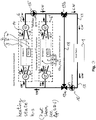
- Figures 3 to 6 show a first embodiment of a heating system according to the invention. Same reference signs in Figures 3 to 6 (and also in Fig. 2 ) relate to the same entities and components, respectively (for clarity reasons, components 16, 17a, 7, 17b are not shown in Figure 3 - however, please compare Figures 4 to 6 ).
- the system layout of this first embodiment is as follows.
- a heat pump 1 is connected (via a first port of it) to a first three-way-valve 13a via a water line 19.
- main pump 10 In water line 19, between heat pump 1 and first valve 13a, main pump 10 is located. That is, one port of valve 13a is connected to main pump 10.
- Another port of valve 13a is connected via a water line 18 and one port of a second three-way-valve 13b to the latter.
- Another port of valve 13b is connected via water line 19 and via a second port of the heat pump 1 to the latter.
- Still another port of valve 13a is connected to still another port of valve 13b via two heat emitting mechanisms 2 and 2' which are fluid-connected in parallel to each other.
- the fluid connection between the two valves 13a and 13b via water line 18, the fluid connection between the two valves 13a and 13b via the second heat emitting mechanism 2', and the fluid connection between the two valves 13a and 13b via the first heat emitting mechanism 2 constitute three fluid-connections which are arranged in parallel to each other.
- the first heat emitting mechanism 2 comprises a first emitter (“Emitter 1") 3 and a first water/PCM heat exchanger 4 (the latter including an area being filled with a phase change material "PCM 1" being depicted with reference sign 5).
- the second heat emitting mechanism 2' comprises a second emitter (“Emitter 2") 3' and a second water/PCM heat exchanger 4' (the latter including an area being filled with a phase change material "PCM 2" being depicted with reference sign 5').
- the respective water/air heat exchanger 3, 3' and the respective water/PCM heat exchanger 4, 4' are fluid-connected in parallel. This is done in the following manner:
- the output port of valve 13a being fluid-connected with the two heat emitting mechanisms 2, 2' is, firstly, connected to a proportional valve 12 which branches into two water lines 8 and 14, namely a PCM throughflow line 8 (being connected to component 4) and an emitter throughflow line 14 (being connected to component 3).
- a proportional valve 12 which branches into two water lines 8 and 14, namely a PCM throughflow line 8 (being connected to component 4) and an emitter throughflow line 14 (being connected to component 3).
- the two lines 8, 14 re-unify (seen from the aforementioned proportional valve 12 shown on the left side of Fig.
- Proportional valve 12' (left side of Fig. 3 ) branches into two lines 8' and 14', wherein line 8' allows a throughflow through elements 4' and 5' and wherein line 14' allows a throughflow through element 3'. Seen from the aforementioned valve 12' (the one being directly connected to valve 13a and being shown on the left side in Figure 3 ), the two lines 8' and 14' then re-unify in another three-way-valve 12' (the one shown on the right side in Figure 3 and being directly connected to valve 13b).
- secondary pump 15 is located in the fluid connecting line part connecting the valve 12 on the right side of Figure 3 with the three-way-valve 13b.
- T-junction fluid connecting part as follows: One port of this T-junction connects to valve 12 on the right side of Fig. 3 via secondary pump 15. Another port of the T-junction connects to valve 12' on the right side of Fig. 3 . Still another port of the T-junction connects to one of the ports of valve 13b.
- the two valves 12, the two lines 8 and 14 and the first heat emitting mechanism 2 (comprising its components 3, 4 and 5) are located in a first room 6 inside a building.
- the two valves 12', the two lines 8' and 14' and the second heat emitting mechanism 2' (with its components 3', 4' and 5') are located in a second room 6' inside this building.
- bypass-valve in the fluid-connecting line part between the aforementioned T-junction and the port of valve 13b which is connected to this T-junction, another valve 16, hereinafter denoted as bypass-valve, is arranged, allowing water flow to 17a and 7 when storing heat or to 13b and 19 when circulating via HP.
- This valve 16 is connected via a bypass line 17 comprising two parts 17a, 17b to valve 13b.
- This bypass connection 17 comprises a large heat store realized as a water tank 7 in between parts 17a and 17b, that is there is a fluid bypass connection between bypass valve 16 via connection line part 17a to tank 7 and from tank 7 via connecting line part 17b to line 18.
- FIG. 3 shows a heating state h-s as follows.
- Hot water HW flows from heat pump 1 (pumped by main pump 10) through three-way-valve 13a into proportional valves 12 and 12' in parallel.
- These valves 12 and 12' are controlled in such a manner that the total amount (i.e. all amount) of hot water HW flowing through them is conducted into the emitter 3 and the emitter 3', respectively (via flow lines 14 and 14').
- no hot water flows (via lines 8, 8') into PCM 5 and into PCM 5'.
- the hot water HW transfers its heat (energy) into the room 6 and the room 6', so that the low room temperature inside these rooms 6, 6' is gradually increased from low room temperature to higher room temperatures. Consequently, the (formerly hot) water having lost its heat flows, as cold water CW, via lines 14, 14' into proportional valves 12, 12' shown on the right side of Figure 3 and is pumped, by secondary pump 15 and through valve 13b, as cold water back into heat pump 1.
- the heat pump 1 in the heating state h-s, the heat pump 1 is switched on, the three-way-valves 13a and 13b are set to feed the emitter circuit (shown as 50 in Figure 5 ).
- Water flow line 18 is not used (i.e. shut off from the water flow via an adequate setting of valves 13a and 13b), the proportional valves 12 and 12' are set so as to completely feed the emitters 3 and 3' and the low room temperature inside rooms 6 and 6' is gradually increased in order to attain, inside rooms 6 and 6' a predefined target temperature T n which is higher than the present room temperature, at a future point in time.
- bypass valve 16 only allows a water flow through it coming from the secondary heat pump 15 side (i.e.
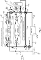
- FIG 4 shows a feed state f-s in form of a state in which heat is fed from heat source/heat pump 1 also into PCM 5 and PCM5' to be stored therein.
- the operation is as shown in Figure 3 so that no only the differences between the shown feed state f-s and the heating state h-s as shown in Figure 3 are described:
- Proportional valves 12, 12' are controlled in a manner such that hot water HW flows out of them into emitters 3, 3' as well as into water/PCM heat exchanger 4, 4' and the PCMs 5, 5' thereof, respectively.
- the setting is such that more water is flowing, via lines 8, 8' into PCMs 5, 5', than is flowing, via lines 14,14', into emitters 3, 3'.
- the heat pump 1 is on and even if proportional valves 12, 12' (of left side) are also used for feeding the emitters 3, 3', said valves 12, 12' are mainly used to feed water/PCM heat exchangers 4, 4' and the PCMs 5, 5' thereof, respectively. That is, in state f-s, mainly heat is fed from the source 1 into the PCMs 5, 5'. Valves 13a and 13b are set to feed the emitter circuit 50 (compare Figure 5 ).
- hot water HW is sucked (by pump 10) via line 19 (on the right hand side of Figs. 3 and 4 ) into heat pump 1, flows through it 1, and is then pumped back (via line 19 on the left hand side of Figs. 3 and 4 ) into the emitter circuit 50 via main pump 10.
- bypass valve 16 is then used as a three-way-valve as follows.
- the secondary pump 15 is a booster pump that maintains water flow through the shown circuit.
- heat pump 1 is shut off and the heat pump circuit 51 (that is, pump 10 and heat pump 1) is disconnected from the emitter circuit 50.
- valves 13a and 13b are set so as to allow a fluid connection between valves 12, 12' shown on the right side of Figure 5 and the valves 12, 12' shown on the left side of Figure 5 via fluid line 18.
- a re-circulated water flow in emitter circuit 50 is established in the following manner. Hot water HW flowing out from valve 12 shown on the right side is pumped, by secondary pump 15, into valve 12' shown on the right side. Only a small fraction of this water HW flows through emitter 3' in order to emit some heat into room 6'. Most of the water flowing out of valve 12' shown on the right flows through PCM 5' in order to take up heat from this PCM.
- the proportional valves 12 are set so as to let most of the re-circulated water flow through emitter 3 to emit heat into room 6 (and only a small part of water flows through water/PCM heat exchanger 4 and its PCM 5, respectively). Consequently, via the hot water HW flowing through line 14, i.e. flowing through emitter 3, room 6 is heated (in order to achieve again T n ) based on heat coming from PCM 5' inside room 6'.
- hot water HW flows via bypass line part 17b, valve 13b, water line 18 and valve 13a (see dotted line) into the emitter circuit 50.
- Hot water HW is re-circulated through components 3, 4 (with 5), 3' and 4' (with 5') based on an operation of components 12, 12' and 15 in emitter circuit 50, while concurrently heat pump circuit 51 is disconnected via valves 13a and 13b and heat pump 1 and main pump 10 are not operating.
- heat can also be drawn from heat store 7 into emitter circuit 50 in order to support keeping the target room temperature inside rooms 6, 6' to the desired level T n as follows.
- Part of the water being circulated in emitter circuit 50 is conducted, via valve 16 and bypass circuit part 17a, through heat store 7.
- water from heat store 7 (which is hot water HW that has been stored before in heat store 7, compare Figure 4 ) is added to the water flowing inside store 7. Consequently, the total amount of water flowing out from store 7 is hotter, that is, has taken up additional heat.
- This total amount is then conducted, via bypass line part 17b and via the two valves 13a and 13b, back into emitter circuit 50. Consequently, also (small portions of) heat being extracted from store 7 are introduced into emitter circuit 50 being in the re-circulated state so as to help maintaining target room temperature inside rooms 6 and 6' to the level of T n .
- Figure 6 shows, in an alternative configuration of the first embodiment (having, in addition to the configuration shown in Figs. 3 to 5 , a totally separate cold water, CW, line 9, with line parts 9a to 9d, see dotted line) a state as follows.
- the totally separate cold water line 9 is used to take heat from PCM 5 either to the heat store 7 or to the emitter 5', as required.
- cold water, CW can flow from a main supply 9' (such as a tap water-connection of the building) through line part 9a directly into PCM 5 (that is, without flowing through valves 12, 12' and 13).
- the CW takes up heat and becomes hot water HW, the latter then flowing out from PCM 5 into line part 9b.
- the HW then either flows, via line part 9c, into heat store 7, or, via line part 9d, into emitter 3'.
- the heat pump 1 is on and only suppling emitter 3.
- the target room temperature T n is achieved, and now room 6 is potentially overheating.
- the main supply is switched on to let cold water, CW, flow through line part 9a into PCM 5 (where it takes up heat from PCM 5).
- the water comes out hot from PCM 5 and flows through emitter 3' (if heat is needed in room 6') or into heat store 7 (if heat shall be stored therein for later use).
- Figure 7 shows three different concepts how PCM 5 and PCM5' can be realized.
- the surface area is maximized for optimized heat transfer between the PCM and the transport fluid (normally: water).
- spiral tubes 8-1 and 8-2 are employed for letting the transport fluid flow through the phase change material 5-1 and 5-2, respectively.
- the phase change material itself is not in the form of encapsulated beads, but in the form of a porous thermal composite, for example, or in it's pure form.
- phase change material 5-3 is realized in an encapsulated bead form in a phase change slurry.
- two parallel fluid lines 8-3 are realized as straight lines running directly through PCM 5-3.
- the fluid lines can be connected to the surface of PCM 5-3.
- the second embodiment shown in Fig 8 is, in principle, realized as the alternative of the first embodiment shown in Fig. 6 and also operates, in principle, like the alternative of the first embodiment shown in Fig. 6 .
- Fig. 6 and Fig. 8 are described hereinafter.
- Fig. 8 shows a case of an independent cold water supply via use of a totally separate cold water line 9.
- both emitters 3 and 3' and both PCMs 5 and 5' are heated up while the heat pump 1 is on.
- cold water line 9 is used (that is, main supply 9' for CW is switched on) to take, via CW flowing through line 9 (which is guided, with two separate line parts, through PCM 5 as well as through PCM 5'), heat from PCM 5 and PCM 5' in rooms 6 and 6' to the PCM battery 9"'. In battery 9"', this heat can be stored for later use.
- PCM battery 9"' can be used for utility services such as for example washing machines, warm water cleaning or can be used as a preheater which is adapted to heat the water prior to the heating of it in the heat pump cycle/circuit 51 (please see Figure 5 ).
Landscapes
- Engineering & Computer Science (AREA)
- Physics & Mathematics (AREA)
- Thermal Sciences (AREA)
- Mechanical Engineering (AREA)
- General Engineering & Computer Science (AREA)
- Chemical & Material Sciences (AREA)
- Combustion & Propulsion (AREA)
- Steam Or Hot-Water Central Heating Systems (AREA)
- Central Heating Systems (AREA)
Abstract
Description
- The present invention relates to a heating system and a heating method.
- Current operation of heating systems having, as a heat source, a heat pump or a boiler and having, as a heat emitter, a fan coil unit or radiator results in long necessary running times of the heat source and overheating of the space in which the heat emitter is installed. Ultimately, this results in a waste of energy.
- It is therefore an objective of the present invention to eliminate these disadvantages. It is especially also an objective of the present invention to improve the heating operation and its control.
- The present invention is described in the independent claims. Advantageous alternatives and options which can be realized, but which are not necessarily to be realized, are described in the dependent claims.
- A basic idea of the present invention is to provide a means of storing excess heat for use at a later stage (and/or at a later time), wherein this means of storing excess heat comprises a phase change material, hereinafter abbreviated as PCM. It is also a basic idea of the present invention to provide a control for different states for the PCM.
- A heating system according to the invention is described in
claim 1. - Therein, being in one of the states (enumerated in this claim) feed state, emission state and transport state and/or changing from one of these enumerated states to another one of these states does not necessarily mean (but can also mean) that all of the heat is flowing in accordance with the respective state. That is, part of the heat (even most of the heat) can also flow in accordance with another one of the enumerated states (or even in accordance with a different state not being enumerated) if the system is controlled so as to be in one of the enumerated states. For example, when intending to heat the first space, part of the heat coming from the heat source can be conveyed to the first space in order to increase the temperature therein, whereas already then another part of the heat coming from the heat source can be fed concurrently to the PCM to be stored in the latter. "Between" means that a change between states can be performed in both directions, for example from the emission state to the feed state and vice versa.
- The heat-transfer-medium can be water. The meaning of heat-transfer-medium/air (especially: water/air) heat exchanger is that heat can be transferred from a heat-transfer-medium (especially: water) to air and vice versa. The meaning of heat-transfer-medium/PCM (especially: water/PCM) heat exchanger is that heat can be transferred from a heat-transfer-medium (especially: water) to a PCM and vice versa.
- Dependent upon its current state, the heat emitting mechanism (that is, the heat-transfer-medium/air heat exchanger thereof and/or the heat storage and release mechanism thereof) can be adapted to emit heat into the first space. The first space is preferably a (first) room inside a building, inside which room preferably not only the heat storage and release mechanism, but also the complete heating mechanism (that is, the heat-transfer-medium/air heat exchanger as well as the heat storage and release mechanism) is located or arranged.
- The controlling of the heating system, especially of the heat storage and release mechanism thereof, may be realized in computer implemented form and/or based on a central control unit of the heating system. This central control unit may be a computer or a microcontroller having a memory (adapted to store adequate control programs) and a microprocessor. Advantageously, controlling means regulating. The controlling/regulating of the heating system, especially of the heat storage and release mechanism thereof, may be realized as a switching of the heat storage and release mechanism in between said (at least) three states (that is, the feed state, the emission state and the transport state), that is from an arbitrary one of these states into another arbitrary one of these states.
- Features that can be advantageously realized (that is, which do not have to be realized) are described in
claim 2. - Also here, "between" means that a change can be performed in both directions.
- Further features that can be advantageously realized are described in
claim 3. - This change can be seen when comparing
Figures 3 and4 (see specific description of embodiments hereinafter). - Further features which can be advantageously realized are described in
claim 4. - The aim of the features described in this claim is to avoid that the target temperature becomes too high in the first space being the target.
- Further advantageous features are described in
claim 5. - The heat-transfer-medium line can be a water-line in case of water being the heat-transfer-medium.
- Further advantageous features are described in
claim 6. - Further advantageous features are described in
claim 7. - In this respect, please compare
Figures 3 and4 , on the one hand, withFigure 5 , on the other hand (these Figures being described in detail hereinafter). Preferably, these state changes can be established based on two, three or more valves, preferably two, three or more three-way-valves. In a preferred embodiment, exactly two three-way-valves are used in order to realize the features of this claim. - Further advantageous features are described in
claim 8. - Preferably, again, the heat-transfer-medium is water.
- Further advantageous features which can be realized are described in claims 9 to 13 (the features of each single one of these claims can be realized solely in conjunction with the features as described in the other claims or can be realized in arbitrary combinations together with the features of the other claims).
- Further advantageous features are described in
claim 14. - Therein, for the fluid-connection of the several heat emitting mechanisms arranged in parallel, please see
Figures 2 to 6 andFigure 8 described in detail hereinafter. - Finally, further advantageous features are described in
claim 15. - A heating method according to the invention is described in
claim 16. - According to the invention, to improve the heating operation and prevent overheating of a space (the first space) by the heat source which equates to energy consumption, empty spaces within heat emitters can be filled with a phase change material (PCM). This phase change material in effect provides a heat storage medium thereby allowing for prolonged heating but with shorter heating and cooling operation cycles of the heat source. The PCM can be regulated to transport heat to a space adapted to store heat, that is a (central) thermal store, or elsewhere to prevent further release of heat into a space (first space) in which the target temperature has already been achieved; thereby minimizing waste of heat and of energy, respectively.
- A hot/cold water circuit, a heat exchanger, and a fan can be combined in order to supply heat and a thermal storage unit which can be composed of a PCM and a heat exchanger can be installed inside the chassis of a heat emitter. The thermal storage unit inside the chassis can supply heat to a room by transferring heat to air by an air flow provided by a fan.
- The PCM can be encapsulated and fitted in the empty space found within the heat emitter. The design and size of encapsulated material will be determined by the heat emitter in use. The PCM in this case can be an encapsulated paraffin or a salt hydrate with a melting temperature between 30°C and 40°C.
- During normal operation of a heat pump, a target room temperature (hereinafter abbreviated as Tn) can be set so as to be achieved by transfer of warm air from the heat emitter to the space/room in question. This target temperature is often surpassed (Troom > Tn), meaning that excess heat enters the room/space to be heated. In the presence of the PCM, this excess heat can be diverted to the PCM for storage thereof, for example via operation of proportional valves, whereby an amount of water flowing in the emitter circuit is reduced and an amount of water flowing to the PCM is increased. A temperature sensor can be used to confirm when Troom = Tn has been achieved (i.e. when Tn has been attained inside the first room/space) and to trigger the proportional valve(s) to divert water flow to the PCM. The proportion of diversion can be based on sensing of the temperature maintained in the space/room to be heated in the first instance.
- When the target temperature in the first space/room is reached and maintained (Troom = Tn = constant), the heat pump can go off. The water can be pumped to a second emitter in a second room/space. The second room is heated and when the target temperature is reached and maintained therein, the heat can then be moved further through the PCM to another and/or next room.
- Thus, the PCM can be regulated and can be integrated in a thermal storage network.
- In the case where two supply and return pipes are employed, heat stored in the PCM (which can comprise several PCM entities) can be moved around (especially: circulated) independently. For example, when heat supplied to the first room reaches the target temperature (Troom = Tn), and heat supplied to the second room is insufficient (Troom < Tn) as determined by one or more temperature sensor(s), heat stored in the thermal storage unit inside the emitter in the first room can be released via a cold water supply to the circuit. Released heat can then be supplied to the second room via a PCM inside an emitter in the second room. The amount of heat released to the second room can be increased by releasing heat stored in a/the PCM.
- When no further space heating is required, heat stored in the PCM can be transported to a large thermal store, for example a water tank, using cold water. (Cold water can be passed through the PCM, resulting in warm water being delivered to the large thermal store, e.g. the water tank, and being stored therein.)
- Alternatively, second heat exchange pipes to heat PCM from within can be used. A variable valve (such as a proportional valve) to regulate flows can be added in each heat exchanger ("HEX"). This allows a very good control of heat emitted to a room, as the PCM can be charged (heated) while the room remains at steady temperature. When the heating is turned off, the PCM allows radiating heat into the room. The PCM can be heated by water after room heating; valves can be manual or automated (e.g. proportional valves).
- In another alternative ("secondary pump"), (a) small pump(s) can be used to move water through the PCM and an air HEX to give boosted heat output from the PCM. (A) valve(s) can be used to stop a remainder of circuit water from flowing through the emitter. This can be done independently of the heat pump being once charged: the space is heated while the heat pump is switched off.
- Also, the same operating principles can be applied to a domestic hot water tank where the PCM is contained between the double layer of the tank body. For example: While the heat pump is running in hot water heating mode, the tank water can be heated to a maximum temperature of 60°C during which time, the PCM can store heat. When the heat pump is switched off, the tank will gradually start to cool, but a higher water temperature will be maintained for longer periods due to heat given off by the PCM.
- Hereinafter, the present invention is described based on specific embodiments. The figures show the following.
-
Figure 1 a prior art heating system. -
Figure 2 the principle layout for a heating system according to the invention. -
Figures 3 to 6 a first embodiment for a heating system according to the invention being in different states. -
Figure 7 three different layouts for a PCM which can be used in the present invention. -
Figure 8 a second embodiment for a heating system according to the present invention. - According to
Figure 1 (prior art), aheat pump 101 is connected via amain pump 110 to a large heat store such as atank 107. Thestore 107 is connected via asecondary pump 115 to theheat pump 101. Consequently,components - In
Figure 1 , in the fluid line between themain pump 110 and theheat store 107, there are two three-way-valves 113b and 113a connected in series. One port of valve 113b is connected via an emitter ("Emitter 2") to the fluid line between thesecondary pump 115 and theheat pump 101. One port of valve 113a (being arranged between valve 113b and heat store 107) is connected via another emitter ("Emitter 1") to the fluid line betweenheat store 107 andsecondary pump 115. The "Emitter 1" is located inside afirst room 106, and the "Emitter 2" is located inside a second room 106' being different from thefirst room 106. - Consequently, the "
Emitter 2" in room 106', the "Emitter 1" inroom 106 and thelarge heat store 107 are respectively fluid-connected in parallel and can be fed (ifmain pump 110 is running) fromheat pump 101. Arrows inFigure 1 (the same also holds for the subsequentFigures 2 to 8 showing the invention) show the current flow of heat-transfer-medium (which is water inFigures 1 to 8 ) according to the current state of the shown system. Therein "HW" stands for "hot water" and "CW" stands for "cold water" (the same abbreviations are also used inFigures 2 to 8 ). - A similar state of the art, which is herein incorporated by reference in order to have described some basic aspects of a heating system, is "Thermo-economic and primary-energy-factor assessment based on the field test of an air-to-water heat pump" by P. Poredos, T. Coz, A. Kitanovski and A. Poredos, in: International Journal of Refrigeration (2017), http://dx.doi.org/doi:10.1016/j.ijrefrig.2017.02.003.
-
Figure 2 shows the basic concept of the present invention. According toFigure 2 , left side, theheat emitting mechanism 2 comprises a water/air heat exchanger 3 and a heat storage andrelease mechanism 4 which is configured as a water/PCM heat exchanger and therefore includes a phasechange material PCM 5. Theheat emitting mechanism 2 further comprises an air-conveying-device 11, which is a fan. Thecomponents 3, 4 (with 5) and 11 are arranged inside a single housing having an air inlet, a duct and an air outlet (see arrows). Theheat emitting mechanism 2 and the housing thereof, resp., allows air to flow through the air inlet inside the housing, therein to fan 11, on the downstream side offan 11 through the duct, on the downstream side of the duct through thecomponent 3 and on the downstream side ofthereof 3 to the air outlet, where the air leaves the housing. The speed of thefan 11 can be manipulated, i.e. varied. An empty space is used to placePCM 5. The surface area between the transport fluid (water) andPCM 5 is maximized. APCM 5 with high thermal conductivity is used. - The basic concept of the hydronic layout inside the emitting mechanism 2 ("hydronic layout inside the emitter") 2 is shown on the right side of
Figure 2 . Inflowing water is conveyed to avariable valve 12 such as a proportional valve.Valve 12 allows variable amounts of inflowing water to flow, on the one hand, through water/PCM heat exchanger 4 and, on the other hand, through water/air heat exchanger 3. Both aforementioned amounts of water are then re-unified at a water outlet. That is, the inflowing total amount of water is divided into two partial amounts of water, the first partial amount of water flowing through water/PCM heat exchanger 4 and the second partial amount of water flowing through water/air heat exchanger 3. The ratio of these two amounts is freely variable according to the setting ofvariable valve 12 between 100% of the total amount of water flowing through water/PCM heat exchanger 4 and 100% of the total amount of water flowing through water/air heat exchanger 3. -
Figures 3 to 6 show a first embodiment of a heating system according to the invention. Same reference signs inFigures 3 to 6 (and also inFig. 2 ) relate to the same entities and components, respectively (for clarity reasons,components Figure 3 - however, please compareFigures 4 to 6 ). - The system layout of this first embodiment is as follows.
- A
heat pump 1 is connected (via a first port of it) to a first three-way-valve 13a via awater line 19. Inwater line 19, betweenheat pump 1 andfirst valve 13a,main pump 10 is located. That is, one port ofvalve 13a is connected tomain pump 10. Another port ofvalve 13a is connected via awater line 18 and one port of a second three-way-valve 13b to the latter. Another port ofvalve 13b is connected viawater line 19 and via a second port of theheat pump 1 to the latter. Still another port ofvalve 13a is connected to still another port ofvalve 13b via twoheat emitting mechanisms 2 and 2' which are fluid-connected in parallel to each other. That is, the fluid connection between the twovalves water line 18, the fluid connection between the twovalves valves heat emitting mechanism 2 constitute three fluid-connections which are arranged in parallel to each other. - The first
heat emitting mechanism 2 comprises a first emitter ("Emitter 1") 3 and a first water/PCM heat exchanger 4 (the latter including an area being filled with a phase change material "PCM 1" being depicted with reference sign 5). The second heat emitting mechanism 2' comprises a second emitter ("Emitter 2") 3' and a second water/PCM heat exchanger 4' (the latter including an area being filled with a phase change material "PCM 2" being depicted with reference sign 5'). - At each of the
heat emitting mechanisms 2 and 2', the respective water/air heat exchanger 3, 3' and the respective water/PCM heat exchanger 4, 4' are fluid-connected in parallel. This is done in the following manner: The output port ofvalve 13a being fluid-connected with the twoheat emitting mechanisms 2, 2' is, firstly, connected to aproportional valve 12 which branches into twowater lines emitter 3, respectively, the twolines proportional valve 12 shown on the left side ofFig. 3 ) into another proportional valve 12 (shown on the right side ofFig. 3 ) which is connected via asecondary pump 15 tovalve 13b. That is,line 14 connects the two aforementionedproportional valves 12 by passing throughemitter 3, whereasline 8 passing through water/PCM heat exchanger 4 (and throughPCM 5 thereof) also fluid-connects the aforementioned twoproportional valves 12 in parallel toline 14. In other words,components component 3, on the other hand, are fluid-connected in parallel between twoproportional valves 12. - The same holds for components (elements) 3', 4' and 5', that is for the second heat emitting mechanism 2'. Proportional valve 12' (left side of
Fig. 3 ) branches into two lines 8' and 14', wherein line 8' allows a throughflow through elements 4' and 5' and wherein line 14' allows a throughflow through element 3'. Seen from the aforementioned valve 12' (the one being directly connected tovalve 13a and being shown on the left side inFigure 3 ), the two lines 8' and 14' then re-unify in another three-way-valve 12' (the one shown on the right side inFigure 3 and being directly connected tovalve 13b). Therein,secondary pump 15 is located in the fluid connecting line part connecting thevalve 12 on the right side ofFigure 3 with the three-way-valve 13b. There is a T-junction fluid connecting part as follows: One port of this T-junction connects tovalve 12 on the right side ofFig. 3 viasecondary pump 15. Another port of the T-junction connects to valve 12' on the right side ofFig. 3 . Still another port of the T-junction connects to one of the ports ofvalve 13b. - The two
valves 12, the twolines components first room 6 inside a building. The two valves 12', the two lines 8' and 14' and the second heat emitting mechanism 2' (with its components 3', 4' and 5') are located in a second room 6' inside this building. - Finally, as can only be seen in
Figures 4 to 6 (but not inFig. 3 ), in this first embodiment, in the fluid-connecting line part between the aforementioned T-junction and the port ofvalve 13b which is connected to this T-junction, anothervalve 16, hereinafter denoted as bypass-valve, is arranged, allowing water flow to 17a and 7 when storing heat or to 13b and 19 when circulating via HP. Thisvalve 16 is connected via abypass line 17 comprising twoparts 17a, 17b tovalve 13b. Thisbypass connection 17 comprises a large heat store realized as awater tank 7 in betweenparts 17a and 17b, that is there is a fluid bypass connection betweenbypass valve 16 viaconnection line part 17a totank 7 and fromtank 7 via connecting line part 17b toline 18. - When storing heat hot water flows from
valve 16 vialine part 17a intoheat store 7. When using heat fromheat store 7, hot water HW flows fromvalve 16 vialine part 17a tostore 7, fromstore 7 via line part 17b intovalve 13b and intoline 18. When there is water circulating via theheat pump 1, the water flow is fromvalve 16 directly tovalve 13b (i.e. without usingbypass - Hereinafter, several operating modes and operating states, resp., of the first embodiment are described with respect to
Figures 3 to 6 . Therein, arrows show the direction of water flowing, wherein "HW" indicates a flow of hot water and "CW" indicates a flow of cold water. -
Figure 3 shows a heating state h-s as follows. Hot water HW flows from heat pump 1 (pumped by main pump 10) through three-way-valve 13a intoproportional valves 12 and 12' in parallel. Thesevalves 12 and 12' are controlled in such a manner that the total amount (i.e. all amount) of hot water HW flowing through them is conducted into theemitter 3 and the emitter 3', respectively (viaflow lines 14 and 14'). In other words, in state h-s, no hot water flows (vialines 8, 8') intoPCM 5 and into PCM 5'. Viaemitters 3, 3', the hot water HW transfers its heat (energy) into theroom 6 and the room 6', so that the low room temperature inside theserooms 6, 6' is gradually increased from low room temperature to higher room temperatures. Consequently, the (formerly hot) water having lost its heat flows, as cold water CW, vialines 14, 14' intoproportional valves 12, 12' shown on the right side ofFigure 3 and is pumped, bysecondary pump 15 and throughvalve 13b, as cold water back intoheat pump 1. - In other words, in the heating state h-s, the
heat pump 1 is switched on, the three-way-valves Figure 5 ).Water flow line 18 is not used (i.e. shut off from the water flow via an adequate setting ofvalves proportional valves 12 and 12' are set so as to completely feed theemitters 3 and 3' and the low room temperature insiderooms 6 and 6' is gradually increased in order to attain, insiderooms 6 and 6' a predefined target temperature Tn which is higher than the present room temperature, at a future point in time. In this heating state h-s,bypass valve 16 only allows a water flow through it coming from thesecondary heat pump 15 side (i.e. fromvalves 12 and 12' on the right side ofFig. 3 ) and going tovalve 13b. That is, thebypass line 17 with itsparts 17a, 17b (and therefore also large heat store 7) is disconnected from the water flow (compareFigure 4 for theaforementioned components -
Figure 4 shows a feed state f-s in form of a state in which heat is fed from heat source/heat pump 1 also intoPCM 5 and PCM5' to be stored therein. In principle, the operation is as shown inFigure 3 so that no only the differences between the shown feed state f-s and the heating state h-s as shown inFigure 3 are described:Proportional valves 12, 12' are controlled in a manner such that hot water HW flows out of them intoemitters 3, 3' as well as into water/PCM heat exchanger 4, 4' and thePCMs 5, 5' thereof, respectively. The setting is such that more water is flowing, vialines 8, 8' intoPCMs 5, 5', than is flowing, vialines 14,14', intoemitters 3, 3'. In the present case, approximately 75 volume-% of the hot water HW is flowing intoPCMs 5, 5', whereas only approximately 25 volume-% of the hot water HW flowing out fromvalves 12, 12' (on the left side ofFigure 4 ) flows intoemitters 3, 3'. - That is, in the shown case f-s, the
heat pump 1 is on and even ifproportional valves 12, 12' (of left side) are also used for feeding theemitters 3, 3', saidvalves 12, 12' are mainly used to feed water/PCM heat exchangers 4, 4' and thePCMs 5, 5' thereof, respectively. That is, in state f-s, mainly heat is fed from thesource 1 into thePCMs 5, 5'.Valves Figure 5 ). - According to the aforementioned situations of
Figs. 3 and4 , hot water HW is sucked (by pump 10) via line 19 (on the right hand side ofFigs. 3 and4 ) intoheat pump 1, flows through it 1, and is then pumped back (vialine 19 on the left hand side ofFigs. 3 and4 ) into theemitter circuit 50 viamain pump 10. - With/during the state shown in
Fig. 4 , the desired target room temperature Tn is practically achieved. After that, it is then an aim to keep this temperature Tn insiderooms 6, 6' constant. That is, after having achieved Tn, hot water HW still flowing intoPCMs 5, 5' (fromvalves 12, 12' on the left side) has to emit its heat and energy, respectively, somewhere else than intorooms 6, 6' (in order to avoid an overheating of these rooms). In order to achieve this, bypassvalve 16 is then used as a three-way-valve as follows. Thesecondary pump 15 is a booster pump that maintains water flow through the shown circuit. Whileheat pumps line 19 andheat pump 1 still continues for part of the hot water HW, another part of the hot water HW is directed, viavalve 16, intobypass 17 to store its heat insidestore 7. Later on, most of the hot water HW flowing intovalve 16 is conducted bybypass 17a intoheat store 7, and finally all of the hot water HW is directed viavalve 16 intotank 7 in order to be stored therein for later use. - Beyond that: In a state when Tn is already achieved in 6 and 6', heat being already pre-stored inside
PCMs 5, 5' is released too according toFig. 4 . This heat released byPCMs 5, 5' can then also be conducted intoheat store 7 in order to avoid an overheating ofspaces 6 and 6'. That is,Figure 4 does not only show a feed state f-s storing heat insidePCMs 5, 5', but also a transport state t-s, in which part of a heat (energy) that is emitted fromPCMs 5, 5' is emitted into a space 7 (i.e. heat store 7) differing from the space being constituted byrooms 6, 6'. - In order to keep the room temperature inside
rooms 6, 6' constant over a longer time, i.e. to maintain the target room temperature Tn insiderooms 6, 6' constant, the operation shown inFigure 5 is used. This operation can be seen as an emission state e-s being a state in which heat stored in thePCMs 5, 5' is emitted intorooms 6, 6' while at the same time in an emission state of theheat store 7 heat (i.e. hot water HW) is conducted via bypass line part 17b andwater line 18 intoemitter circuit 50. - Specifically, in the operation according to
Figure 5 ,heat pump 1 is shut off and the heat pump circuit 51 (that is, pump 10 and heat pump 1) is disconnected from theemitter circuit 50. In order to achieve this,valves valves 12, 12' shown on the right side ofFigure 5 and thevalves 12, 12' shown on the left side ofFigure 5 viafluid line 18. In other words, a re-circulated water flow inemitter circuit 50 is established in the following manner. Hot water HW flowing out fromvalve 12 shown on the right side is pumped, bysecondary pump 15, into valve 12' shown on the right side. Only a small fraction of this water HW flows through emitter 3' in order to emit some heat into room 6'. Most of the water flowing out of valve 12' shown on the right flows through PCM 5' in order to take up heat from this PCM. - That is, in
Figure 5 , there is the following operating situation. - In
room 6, the temperature has presently dropped slightly below the desired temperature Tn, whereas in room 6', the temperature is still Tn. Consequently, heat emitted by PCM 5' flows through valve 12' shown on the left side and is re-circulated intoroom 6, i.e. intovalve 12 shown on the left side. Because inside room 6', temperature is still Tn (as desired), the two proportional valves 12' are set so as to let most of the water (for example approximately 90% of the water volume) flow through water/PCM heat exchanger 4' and its PCM 5', respectively (whereas only a small amount of water flowing through emitting mechanism 2' flows through emitter 3', here for example 10 vol-%). As insideroom 6, temperature has already dropped slightly below Tn, theproportional valves 12 are set so as to let most of the re-circulated water flow throughemitter 3 to emit heat into room 6 (and only a small part of water flows through water/PCM heat exchanger 4 and itsPCM 5, respectively). Consequently, via the hot water HW flowing throughline 14, i.e. flowing throughemitter 3,room 6 is heated (in order to achieve again Tn) based on heat coming from PCM 5' inside room 6'. - Also, according to
Fig. 5 , as heat from theheat store 7 is used, hot water HW flows via bypass line part 17b,valve 13b,water line 18 andvalve 13a (see dotted line) into theemitter circuit 50. - This re-circulating status of
emitter circuit 50 is maintained based on operation of secondary pump 15: Hot water HW is re-circulated throughcomponents 3, 4 (with 5), 3' and 4' (with 5') based on an operation ofcomponents emitter circuit 50, while concurrentlyheat pump circuit 51 is disconnected viavalves heat pump 1 andmain pump 10 are not operating. - This leads to the desired balance in temperature so that the temperature inside
rooms 6 and 6' can be maintained more or less to the desired value of Tn. (InFigure 5 , as temperature has slightly dropped inroom 6, whereas in room 6' there the temperature is still at level Tn, water from PCM 5' is passed throughemitter 3 to achieve Tn so that heat from PCM 5' to drawn back toemitter 3 inroom 6.) - The reverse is also possible: If, in room 6', temperature T drops slightly below the desired temperature Tn, whereas in
room 6, the temperature is still Tn, water is passed through emitter 3' to re-achieve Tn in room 6' and throughPCM 5 to draw heat back to emitter 3' inside room 6'. (With time running, the water inemitter circuit 50 would cool down, therefore, the heat fromPCMs 5, 5' is moved around to heat therooms 6 and 6'.) - In addition, heat can also be drawn from
heat store 7 intoemitter circuit 50 in order to support keeping the target room temperature insiderooms 6, 6' to the desired level Tn as follows. Part of the water being circulated inemitter circuit 50 is conducted, viavalve 16 andbypass circuit part 17a, throughheat store 7. Instore 7, water from heat store 7 (which is hot water HW that has been stored before inheat store 7, compareFigure 4 ) is added to the water flowing insidestore 7. Consequently, the total amount of water flowing out fromstore 7 is hotter, that is, has taken up additional heat. This total amount is then conducted, via bypass line part 17b and via the twovalves emitter circuit 50. Consequently, also (small portions of) heat being extracted fromstore 7 are introduced intoemitter circuit 50 being in the re-circulated state so as to help maintaining target room temperature insiderooms 6 and 6' to the level of Tn. - In
Figure 6 , for clarity reasons, not all reference signs have been provided (the same holds for the second embodiment ofFigure 8 which is described below).Figure 6 shows, in an alternative configuration of the first embodiment (having, in addition to the configuration shown inFigs. 3 to 5 , a totally separate cold water, CW, line 9, with line parts 9a to 9d, see dotted line) a state as follows. - The totally separate cold water line 9 is used to take heat from
PCM 5 either to theheat store 7 or to the emitter 5', as required. In line 9, cold water, CW, can flow from a main supply 9' (such as a tap water-connection of the building) through line part 9a directly into PCM 5 (that is, without flowing throughvalves 12, 12' and 13). InPCM 5, the CW takes up heat and becomes hot water HW, the latter then flowing out fromPCM 5 into line part 9b. Dependent upon the switching state of valve 9" (which connects line part 9b to lineparts 9c and 9d), the HW then either flows, via line part 9c, intoheat store 7, or, vialine part 9d, into emitter 3'. - In the alternative of the first embodiment shown in
Fig 6 , theheat pump 1 is on and only supplingemitter 3. The target room temperature Tn is achieved, and nowroom 6 is potentially overheating. In order to avoid this, the main supply is switched on to let cold water, CW, flow through line part 9a into PCM 5 (where it takes up heat from PCM 5). The water comes out hot fromPCM 5 and flows through emitter 3' (if heat is needed in room 6') or into heat store 7 (if heat shall be stored therein for later use). -
Figure 7 shows three different concepts howPCM 5 and PCM5' can be realized. - According to all three alternatives I to iii shown in
Figure 7 , the surface area is maximized for optimized heat transfer between the PCM and the transport fluid (normally: water). - According to alternatives i and ii, spiral tubes 8-1 and 8-2, resp., are employed for letting the transport fluid flow through the phase change material 5-1 and 5-2, respectively. In these alternatives i and ii, the phase change material itself is not in the form of encapsulated beads, but in the form of a porous thermal composite, for example, or in it's pure form.
- In the alternative iii, the phase change material 5-3 is realized in an encapsulated bead form in a phase change slurry. In this case, two parallel fluid lines 8-3 are realized as straight lines running directly through PCM 5-3. Alternatively, the fluid lines can be connected to the surface of PCM 5-3.
- The second embodiment shown in
Fig 8 is, in principle, realized as the alternative of the first embodiment shown inFig. 6 and also operates, in principle, like the alternative of the first embodiment shown inFig. 6 . Thus, only the differences betweenFig. 6 andFig. 8 are described hereinafter. - Also
Fig. 8 shows a case of an independent cold water supply via use of a totally separate cold water line 9. However, inFig. 8 , bothemitters 3 and 3' and bothPCMs 5 and 5' are heated up while theheat pump 1 is on. When the desired room temperature Tn is achieved, cold water line 9 is used (that is, main supply 9' for CW is switched on) to take, via CW flowing through line 9 (which is guided, with two separate line parts, throughPCM 5 as well as through PCM 5'), heat fromPCM 5 and PCM 5' inrooms 6 and 6' to the PCM battery 9"'. In battery 9"', this heat can be stored for later use. - According to
Figure 8 , PCM battery 9"' can be used for utility services such as for example washing machines, warm water cleaning or can be used as a preheater which is adapted to heat the water prior to the heating of it in the heat pump cycle/circuit 51 (please seeFigure 5 ).
Claims (16)
- Heating system with a heat source (1) and a heat emitting mechanism (2),
wherein the heat emitting mechanism (2) comprises a heat-transfer-medium/air heat exchanger (3) and a heat storage and release mechanism (4),
wherein the heat storage and release mechanism (4) has a phase change material (5), the latter hereinafter being abbreviated as PCM (5), and the heat storage and release mechanism (4) is configured as a heat-transfer-medium/PCM heat exchanger, and
wherein the heating system, preferably the heat storage and release mechanism (4) thereof, can be controlled so as to be changed between• a feed state (f-s) being a state in which heat fed from the heat source (1) is stored in the PCM (5),• an emission state (e-s) being a state in which heat stored in the PCM (5) is emitted into a first space (6) within which the heat storage and release mechanism (4) is located,and• a transport state (t-s) being a state in which not all of the heat being released by the PCM (5) is emitted into the first space (6), but at least part of the heat being released by the PCM (5) is emitted into a second space (6', 7) differing from the first space (6), preferably the transport state (t-s) being a state in which an emission of heat being released by the PCM (5) into the first space (6) is prevented by means of conveying the heat being released by the PCM (5) into the second space (6', 7) differing from the first space (6). - Heating system according to the preceding claim
characterized in that
the heating system can be controlled so as to be changed between at least one of, preferably between each one of, the feed state (f-s), the emission state (e-s) and/or the transport state (t-s), on the one hand, and a heating state (h-s) being a state in which heat from the heat source (1) is fed to the heat-transfer-medium/air heat exchanger (3) in order to heat the air of the first space (6). - Heating system according to the preceding claim
characterized in that
the heating system can be controlled so as to be changed from the heating state (h-s) to the feed state (f-s) if a predefined fraction of a predefined temperature (target temperature, Tn) is attained in the first space (6),
preferably said fraction being 90%, 95%, 98% or 99% of the target temperature (Tn). - Heating system according to one of the preceding claims
characterized in that
the heating system can be controlled so as to be changed from the emission state (e-s) to the transport state (t-s) if a predefined multiple of a predefined temperature (target temperature, Tn) is exceeded in the first space (6),
preferably said multiple being 110%, 105%, 102% or 101% of the target temperature (Tn). - Heating system according to one of the preceding claims
characterized by
a heat-transfer-medium line (8) disposed so as to transfer heat from the PCM (5) to a heat-transfer-medium being conveyed inside it (8) in case of said heat-transfer-medium having a lower temperature than the PCM (5) and to transfer heat from a heat-transfer-medium being conveyed inside it (8) to the PCM (5) a in case of said heat-transfer-medium having a higher temperature than the PCM (5),
preferably said heat-transfer-medium line (8) being, at least in sections, wound around the PCM (5), arranged on a surface of the PCM (5), and/or passing through the PCM (5). - Heating system according to the preceding claim
characterized in that
a fluid connection between the heat-transfer-medium line (8) and the heat source (1). - Heating system according to one of the preceding claims
characterized in that
the heating system can be changed, preferably can be switched, from a state in which the heat emitting mechanism (2) is fluid-connected with the heat source (1) to a state in which the fluid-connection between the heat emitting mechanism (2) and the heat source (1) is disconnected and vice versa. - Heating system according to one of the preceding claims
characterized in that
the second space (6', 7) differing from the first space (6) comprises a space adapted to store heat, preferably a thermal storing space, preferably a tank (7) filled or to be filled with a heat-transfer-medium,
wherein preferably the first space (6) is a first room and the second space (6', 7) differing from the first space (6) comprises a second room (6') differing from said first room and, in addition to said second room (6'), and said tank (7) filled or to be filled with said heat-transfer-medium. - Heating system according to one of the preceding claims
characterized in that
the heat emitting mechanism (2) further comprises an air-conveying-device (11), preferably a fan or a radiator. - Heating system according to the preceding claim
characterized in that
the phase change material (5) of the heat storage and release mechanism (4) is, at least in sections, arranged in the interior of the air-conveying-device (11). - Heating system according to one of the preceding claims
characterized by
a flow ratio control unit (12), preferably a proportional valve, being adapted to control the ratio of heat-transfer-medium being fed to the heat-transfer-medium/air heat exchanger (3) and of heat-transfer-medium being fed to the heat storage and release mechanism (4). - Heating system according to one of the preceding claims
characterized in that
the heat source (1) comprises or is a heat pump. - Heating system according to one of the preceding claims
characterized in that
the heat-transfer-medium/air heat exchanger (3) and the heat storage and release mechanism (4) are fluid-connected in parallel. - Heating system according to one of the preceding claims
characterized by
several heat emitting mechanisms (2, 2'),
wherein each heat emitting mechanism (2, 2') comprises a heat-transfer-medium/air heat exchanger (3, 3') and a heat storage and release mechanism (4, 4') in such a manner that the respective heat-transfer-medium/air heat exchanger (3, 3') and the respective heat storage and release mechanism (4, 4') are fluid-connected in parallel, and
wherein the several heat emitting mechanisms (2, 2') are either fluid-connected in parallel or fluid-connected in series. - Heating system according to one of the preceding claims
characterized by
the PCM (5) comprising or being• a salt hydrate, especially calcium chloride or sodium acetate,
wherein advantageously the emitter contains a protective coating so as to avoid corrosion and/or encapsulated propylene glycol, sodium nitrate or potassium nitrate,• a PCM with phase transition between 0° Celsius and 50° Celsius,and/or• a metal matrix composite, preferably utilising copper or aluminium, with preferably a thermal conductivity of ≥ 35 W/m°K, preferably of ≥ 50 W/m°K. - Heating method using a heating system according to one of the preceding claims, that is
a heating system with a heat source (1) and a heat emitting mechanism (2), wherein the heat emitting mechanism (2) comprises a heat-transfer-medium/air heat exchanger (3) and a heat storage and release mechanism (4), and wherein the heat storage and release mechanism (4) has a phase change material (5), the latter hereinafter being abbreviated as PCM (5), and the heat storage and release mechanism (4) is configured as a heat-transfer-medium/PCM heat exchanger,
characterized in that
wherein the heating system, preferably the heat storage and release mechanism (4) thereof, is controlled so as to be changed between• a feed state (f-s) being a state in which heat fed from the heat source (1) is stored in the PCM (5),• an emission state (e-s) being a state in which heat stored in the PCM (5) is emitted into a first space (6) within which the heat storage and release mechanism (4) is located,and• a transport state (t-s) being a state in which not all of the heat being released by the PCM (5) is emitted into the first space (6), but at least part of the heat being released by the PCM (5) is emitted into a second space (6', 7) differing from the first space (6), preferably the transport state (t-s) being a state in which an emission of heat being released by the PCM (5) into the first space (6) is prevented by means of conveying the heat being released by the PCM (5) into the second space (6', 7) differing from the first space (6).
Priority Applications (2)
| Application Number | Priority Date | Filing Date | Title |
|---|---|---|---|
| EP17164194.7A EP3382292B1 (en) | 2017-03-31 | 2017-03-31 | Heating system and heating method |
| JP2018063496A JP2018173261A (en) | 2017-03-31 | 2018-03-29 | Heating system and heating method |
Applications Claiming Priority (1)
| Application Number | Priority Date | Filing Date | Title |
|---|---|---|---|
| EP17164194.7A EP3382292B1 (en) | 2017-03-31 | 2017-03-31 | Heating system and heating method |
Publications (2)
| Publication Number | Publication Date |
|---|---|
| EP3382292A1 true EP3382292A1 (en) | 2018-10-03 |
| EP3382292B1 EP3382292B1 (en) | 2026-04-29 |
Family
ID=58488833
Family Applications (1)
| Application Number | Title | Priority Date | Filing Date |
|---|---|---|---|
| EP17164194.7A Active EP3382292B1 (en) | 2017-03-31 | 2017-03-31 | Heating system and heating method |
Country Status (2)
| Country | Link |
|---|---|
| EP (1) | EP3382292B1 (en) |
| JP (1) | JP2018173261A (en) |
Cited By (5)
| Publication number | Priority date | Publication date | Assignee | Title |
|---|---|---|---|---|
| CN109764400A (en) * | 2019-03-07 | 2019-05-17 | 北京市热力集团有限责任公司 | Heat supply network, underground heat cross-season heat-storing, heat supply method and system |
| CN112303770A (en) * | 2020-11-17 | 2021-02-02 | 深圳市柏涛蓝森国际建筑设计有限公司 | Central air-conditioning water system based on secondary pump and control method |
| IT201900021033A1 (en) * | 2019-11-13 | 2021-05-13 | I Tes S R L | HEATING TERMINAL DEVICE CONTAINING A PHASE CHANGE MATERIAL |
| EP3948095A4 (en) * | 2019-04-04 | 2023-05-03 | Stash Energy Inc. | HEATING AND COOLING SYSTEMS AND APPLIANCES WITH PHASE CHANGE MATERIALS |
| CN117167863A (en) * | 2023-10-08 | 2023-12-05 | 珠海格力电器股份有限公司 | Multi-zone water flow control methods, waterway systems, devices and electronic equipment |
Families Citing this family (1)
| Publication number | Priority date | Publication date | Assignee | Title |
|---|---|---|---|---|
| DE102022209704A1 (en) * | 2022-09-15 | 2024-03-21 | Siemens Energy Global GmbH & Co. KG | Method and device for integrating heat into a district heating network |
Citations (2)
| Publication number | Priority date | Publication date | Assignee | Title |
|---|---|---|---|---|
| EP1455156A2 (en) * | 2003-03-04 | 2004-09-08 | Imtech Deutschland GmbH & Co. KG | Room temperature conditioner |
| DE102015207079A1 (en) * | 2015-04-20 | 2016-10-20 | Vaillant Gmbh | heating system |
-
2017
- 2017-03-31 EP EP17164194.7A patent/EP3382292B1/en active Active
-
2018
- 2018-03-29 JP JP2018063496A patent/JP2018173261A/en active Pending
Patent Citations (2)
| Publication number | Priority date | Publication date | Assignee | Title |
|---|---|---|---|---|
| EP1455156A2 (en) * | 2003-03-04 | 2004-09-08 | Imtech Deutschland GmbH & Co. KG | Room temperature conditioner |
| DE102015207079A1 (en) * | 2015-04-20 | 2016-10-20 | Vaillant Gmbh | heating system |
Non-Patent Citations (1)
| Title |
|---|
| P. POREDOS; T. COZ; A. KITANOVSKI; A. POREDOS: "Thermo-economic and primary-energy-factor assessment based on the field test of an air-to-water heat pump", INTERNATIONAL JOURNAL OF REFRIGERATION, 2017, Retrieved from the Internet <URL:http://dx.doi.Org/doi:10.1016/i.iirefrig.2017.02.003> |
Cited By (7)
| Publication number | Priority date | Publication date | Assignee | Title |
|---|---|---|---|---|
| CN109764400A (en) * | 2019-03-07 | 2019-05-17 | 北京市热力集团有限责任公司 | Heat supply network, underground heat cross-season heat-storing, heat supply method and system |
| CN109764400B (en) * | 2019-03-07 | 2023-04-28 | 北京市热力集团有限责任公司 | Heat supply network, geothermal heat storage and heat supply method and system across seasons |
| EP3948095A4 (en) * | 2019-04-04 | 2023-05-03 | Stash Energy Inc. | HEATING AND COOLING SYSTEMS AND APPLIANCES WITH PHASE CHANGE MATERIALS |
| US11994348B2 (en) | 2019-04-04 | 2024-05-28 | Stash Energy Inc. | Heating and cooling systems and apparatuses with phase change materials |
| IT201900021033A1 (en) * | 2019-11-13 | 2021-05-13 | I Tes S R L | HEATING TERMINAL DEVICE CONTAINING A PHASE CHANGE MATERIAL |
| CN112303770A (en) * | 2020-11-17 | 2021-02-02 | 深圳市柏涛蓝森国际建筑设计有限公司 | Central air-conditioning water system based on secondary pump and control method |
| CN117167863A (en) * | 2023-10-08 | 2023-12-05 | 珠海格力电器股份有限公司 | Multi-zone water flow control methods, waterway systems, devices and electronic equipment |
Also Published As
| Publication number | Publication date |
|---|---|
| EP3382292B1 (en) | 2026-04-29 |
| JP2018173261A (en) | 2018-11-08 |
Similar Documents
| Publication | Publication Date | Title |
|---|---|---|
| EP3382292B1 (en) | Heating system and heating method | |
| US7913501B2 (en) | Water-cooled air conditioning system using condenser water regeneration for precise air reheat in dehumidifying mode | |
| JP5087484B2 (en) | Hot water storage hot water heater | |
| CN105264305A (en) | Apparatus and methods for pre-heating water with air conditioning unit or water pump | |
| US11976861B2 (en) | Electric heating and cooling system | |
| EP3376121A1 (en) | Heat exchange device and method for operating a heat exchange device | |
| JP4934009B2 (en) | Heat source water supply system | |
| CN116848358A (en) | Systems for generating heat for domestic hot water or central heating | |
| JP4030394B2 (en) | Hot water storage water heater | |
| JP2019536970A (en) | Hot water and energy storage | |
| KR101252786B1 (en) | Heating and method for controlling the heating | |
| EP3803217B1 (en) | Heating and cooling system, corresponding method and use of the system | |
| JP4169452B2 (en) | Water heater | |
| JP6663740B2 (en) | Heat utilization system | |
| JP4953436B2 (en) | Thermal storage and heat dissipation system | |
| JP2002364912A (en) | Multifunctional water heater | |
| CN114556024A (en) | Energy system and method and data carrier comprising instructions thereof | |
| JP2008107080A (en) | Floor heating system | |
| JP7574461B2 (en) | Systems for generating heat for domestic hot water or central heating | |
| DK3255355T3 (en) | HEATING INSTALLATION WITH INTEGRATED HYDRAULIC STEP STRUCTURE | |
| KR102869998B1 (en) | Water heat storage type air conditioning and heating system comprising big temperature difference water circuit and automatic control | |
| CN221780815U (en) | Environmental Control System | |
| EP3091293B1 (en) | Heating device | |
| EP4435333A1 (en) | Heat pump system with self-consumption management and demand response functions | |
| JP2010267565A (en) | Fuel cell system |
Legal Events
| Date | Code | Title | Description |
|---|---|---|---|
| PUAI | Public reference made under article 153(3) epc to a published international application that has entered the european phase |
Free format text: ORIGINAL CODE: 0009012 |
|
| STAA | Information on the status of an ep patent application or granted ep patent |
Free format text: STATUS: THE APPLICATION HAS BEEN PUBLISHED |
|
| AK | Designated contracting states |
Kind code of ref document: A1 Designated state(s): AL AT BE BG CH CY CZ DE DK EE ES FI FR GB GR HR HU IE IS IT LI LT LU LV MC MK MT NL NO PL PT RO RS SE SI SK SM TR |
|
| AX | Request for extension of the european patent |
Extension state: BA ME |
|
| STAA | Information on the status of an ep patent application or granted ep patent |
Free format text: STATUS: REQUEST FOR EXAMINATION WAS MADE |
|
| 17P | Request for examination filed |
Effective date: 20190315 |
|
| RBV | Designated contracting states (corrected) |
Designated state(s): AL AT BE BG CH CY CZ DE DK EE ES FI FR GB GR HR HU IE IS IT LI LT LU LV MC MK MT NL NO PL PT RO RS SE SI SK SM TR |
|
| STAA | Information on the status of an ep patent application or granted ep patent |
Free format text: STATUS: EXAMINATION IS IN PROGRESS |
|
| 17Q | First examination report despatched |
Effective date: 20200211 |
|
| P01 | Opt-out of the competence of the unified patent court (upc) registered |
Effective date: 20230330 |
|
| P02 | Opt-out of the competence of the unified patent court (upc) changed |
Effective date: 20230513 |
|
| GRAP | Despatch of communication of intention to grant a patent |
Free format text: ORIGINAL CODE: EPIDOSNIGR1 |
|
| STAA | Information on the status of an ep patent application or granted ep patent |
Free format text: STATUS: GRANT OF PATENT IS INTENDED |
|
| INTG | Intention to grant announced |
Effective date: 20251120 |
|
| GRAS | Grant fee paid |
Free format text: ORIGINAL CODE: EPIDOSNIGR3 |
|
| GRAA | (expected) grant |
Free format text: ORIGINAL CODE: 0009210 |
|
| STAA | Information on the status of an ep patent application or granted ep patent |
Free format text: STATUS: THE PATENT HAS BEEN GRANTED |
|
| RAP1 | Party data changed (applicant data changed or rights of an application transferred) |
Owner name: MITSUBISHI ELECTRIC CORPORATION |
|
| AK | Designated contracting states |
Kind code of ref document: B1 Designated state(s): AL AT BE BG CH CY CZ DE DK EE ES FI FR GB GR HR HU IE IS IT LI LT LU LV MC MK MT NL NO PL PT RO RS SE SI SK SM TR |
|
| REG | Reference to a national code |
Ref country code: CH Ref legal event code: F10 Free format text: ST27 STATUS EVENT CODE: U-0-0-F10-F00 (AS PROVIDED BY THE NATIONAL OFFICE) Effective date: 20260429 Ref country code: GB Ref legal event code: FG4D |