EP3382254A1 - Beheizte rohrleitung mit stecker sowie ein verfahren zum betrieb dieser rohrleitung - Google Patents
Beheizte rohrleitung mit stecker sowie ein verfahren zum betrieb dieser rohrleitung Download PDFInfo
- Publication number
- EP3382254A1 EP3382254A1 EP17163623.6A EP17163623A EP3382254A1 EP 3382254 A1 EP3382254 A1 EP 3382254A1 EP 17163623 A EP17163623 A EP 17163623A EP 3382254 A1 EP3382254 A1 EP 3382254A1
- Authority
- EP
- European Patent Office
- Prior art keywords
- heating wire
- tube
- plug
- housing
- plug shank
- Prior art date
- Legal status (The legal status is an assumption and is not a legal conclusion. Google has not performed a legal analysis and makes no representation as to the accuracy of the status listed.)
- Granted
Links
Images


Classifications
-
- F—MECHANICAL ENGINEERING; LIGHTING; HEATING; WEAPONS; BLASTING
- F01—MACHINES OR ENGINES IN GENERAL; ENGINE PLANTS IN GENERAL; STEAM ENGINES
- F01N—GAS-FLOW SILENCERS OR EXHAUST APPARATUS FOR MACHINES OR ENGINES IN GENERAL; GAS-FLOW SILENCERS OR EXHAUST APPARATUS FOR INTERNAL-COMBUSTION ENGINES
- F01N3/00—Exhaust or silencing apparatus having means for purifying, rendering innocuous, or otherwise treating exhaust
- F01N3/08—Exhaust or silencing apparatus having means for purifying, rendering innocuous, or otherwise treating exhaust for rendering innocuous
- F01N3/10—Exhaust or silencing apparatus having means for purifying, rendering innocuous, or otherwise treating exhaust for rendering innocuous by thermal or catalytic conversion of noxious components of exhaust
- F01N3/18—Exhaust or silencing apparatus having means for purifying, rendering innocuous, or otherwise treating exhaust for rendering innocuous by thermal or catalytic conversion of noxious components of exhaust characterised by methods of operation; Control
- F01N3/20—Exhaust or silencing apparatus having means for purifying, rendering innocuous, or otherwise treating exhaust for rendering innocuous by thermal or catalytic conversion of noxious components of exhaust characterised by methods of operation; Control specially adapted for catalytic conversion
- F01N3/206—Adding periodically or continuously substances to exhaust gases for promoting purification, e.g. catalytic material in liquid form, NOx reducing agents
- F01N3/2066—Selective catalytic reduction [SCR]
-
- F—MECHANICAL ENGINEERING; LIGHTING; HEATING; WEAPONS; BLASTING
- F16—ENGINEERING ELEMENTS AND UNITS; GENERAL MEASURES FOR PRODUCING AND MAINTAINING EFFECTIVE FUNCTIONING OF MACHINES OR INSTALLATIONS; THERMAL INSULATION IN GENERAL
- F16L—PIPES; JOINTS OR FITTINGS FOR PIPES; SUPPORTS FOR PIPES, CABLES OR PROTECTIVE TUBING; MEANS FOR THERMAL INSULATION IN GENERAL
- F16L53/00—Heating of pipes or pipe systems; Cooling of pipes or pipe systems
- F16L53/30—Heating of pipes or pipe systems
- F16L53/35—Ohmic-resistance heating
- F16L53/38—Ohmic-resistance heating using elongate electric heating elements, e.g. wires or ribbons
-
- F—MECHANICAL ENGINEERING; LIGHTING; HEATING; WEAPONS; BLASTING
- F01—MACHINES OR ENGINES IN GENERAL; ENGINE PLANTS IN GENERAL; STEAM ENGINES
- F01N—GAS-FLOW SILENCERS OR EXHAUST APPARATUS FOR MACHINES OR ENGINES IN GENERAL; GAS-FLOW SILENCERS OR EXHAUST APPARATUS FOR INTERNAL-COMBUSTION ENGINES
- F01N2610/00—Adding substances to exhaust gases
- F01N2610/02—Adding substances to exhaust gases the substance being ammonia or urea
-
- F—MECHANICAL ENGINEERING; LIGHTING; HEATING; WEAPONS; BLASTING
- F01—MACHINES OR ENGINES IN GENERAL; ENGINE PLANTS IN GENERAL; STEAM ENGINES
- F01N—GAS-FLOW SILENCERS OR EXHAUST APPARATUS FOR MACHINES OR ENGINES IN GENERAL; GAS-FLOW SILENCERS OR EXHAUST APPARATUS FOR INTERNAL-COMBUSTION ENGINES
- F01N2610/00—Adding substances to exhaust gases
- F01N2610/10—Adding substances to exhaust gases the substance being heated, e.g. by heating tank or supply line of the added substance
-
- F—MECHANICAL ENGINEERING; LIGHTING; HEATING; WEAPONS; BLASTING
- F01—MACHINES OR ENGINES IN GENERAL; ENGINE PLANTS IN GENERAL; STEAM ENGINES
- F01N—GAS-FLOW SILENCERS OR EXHAUST APPARATUS FOR MACHINES OR ENGINES IN GENERAL; GAS-FLOW SILENCERS OR EXHAUST APPARATUS FOR INTERNAL-COMBUSTION ENGINES
- F01N2610/00—Adding substances to exhaust gases
- F01N2610/14—Arrangements for the supply of substances, e.g. conduits
- F01N2610/1486—Means to prevent the substance from freezing
-
- Y—GENERAL TAGGING OF NEW TECHNOLOGICAL DEVELOPMENTS; GENERAL TAGGING OF CROSS-SECTIONAL TECHNOLOGIES SPANNING OVER SEVERAL SECTIONS OF THE IPC; TECHNICAL SUBJECTS COVERED BY FORMER USPC CROSS-REFERENCE ART COLLECTIONS [XRACs] AND DIGESTS
- Y02—TECHNOLOGIES OR APPLICATIONS FOR MITIGATION OR ADAPTATION AGAINST CLIMATE CHANGE
- Y02A—TECHNOLOGIES FOR ADAPTATION TO CLIMATE CHANGE
- Y02A50/00—TECHNOLOGIES FOR ADAPTATION TO CLIMATE CHANGE in human health protection, e.g. against extreme weather
- Y02A50/20—Air quality improvement or preservation, e.g. vehicle emission control or emission reduction by using catalytic converters
Definitions
- the invention relates to a pipeline for a fluid medium of motor vehicles, in particular for an aqueous urea solution, comprising a tube, at least one heating wire and arranged at a pipe end of the pipe connector, wherein the plug has a plug shank and a housing surrounding the pipe end and the heating wire wherein the plug shank comprises a latching means, preferably a collar, for latching in a connector.
- Such a pipeline is made, for example EP 2 171 337 B1 known.
- the tube shown therein has an inner tube and a contact element in the form of an adhesive tape, wherein the contact element brings two double helix-shaped mutually arranged heating wires on the inner tube to the plant.
- the arrangement of inner tube, heating wires and contact element is also surrounded by a protective tube in the form of a corrugated pipe.
- the housing of the plug surrounds the contact element partially, wherein dissolve within the housing, the heating wires of the inner tube.
- the heating wires are connected via electrical connections with another heating wire of the plug shank.
- the heating wire of the plug shank is guided helically by helical grooves or by a flat groove on the plug shank.
- Both the helical groove and the planar groove are alignment elements which serve to guide the heating wire.
- the housing extends from the tube end beyond the alignment elements to the tip of the plug shank.
- the housing of the plug shank also on locking means which interact with complementary locking means in the connector and so produce the latching connection.
- a disadvantage is considered that the heating wire is disposed on the plug shank, which means a complex production. There is also the risk of leakage if the housing of the plug shank is damaged, because then the locking means of the plug shank can slip out of the complementary locking means of the connector.
- the invention is therefore the technical object of specifying a pipe with plug shank, in which the manufacturing cost is reduced and / or wherein the locking connection between the plug and connector is formed safer.
- the invention teaches a pipeline for a fluid medium of motor vehicles, in particular for an aqueous urea solution, comprising a tube, at least one heating wire and arranged at a pipe end of the pipe connector, wherein the plug has a plug shank and a pipe end and the Comprising heating wire enclosing housing, wherein the plug shank comprises a latching means, preferably a collar, for latching in a connector, wherein the tube has an inner tube and a contact element, wherein the heating wire is arranged between the inner tube and the contact element, wherein the contact element brings the heating wire on the inner tube to the plant, wherein the housing partially encloses the contact element, wherein a first portion of the heating wire at the pipe end between the contact element and the inner tube and wherein a second portion of the heating wire between the contact element and the housing extends.
- the plug shank comprises a latching means, preferably a collar, for latching in a connector
- the tube has an inner tube and a contact element, where
- the invention is based on the finding that a sufficient length of the heating wire in the housing can be accommodated by the additional course of the heating wire between the contact element and the housing, so that the entire plug is sufficiently heated. A mechanically and manually consuming spiraling is then no longer necessary on the plug shank. In addition, it also requires no far-reaching enclosure of the plug shank through the housing, so that the plug shank itself may have the locking means. Since the plug shank is much more compact than the housing and can be integrally formed (from a cast), it is much more stable and as a result, a correspondingly prepared locking connection is much safer.
- inner tube means in particular a separate and preferably a separately extruded tube part.
- the inner tube may also be an inner wall portion of the separate pipe part.
- contact element means, in particular, an adhesive tape and / or a heat-shrinkable tube and / or an outer wall section of the separate tubular part.
- tube end means, in particular, the section of the tube enclosed by the housing, including the front end of the tube associated with the plug shank.
- portion means a portion of axial alignment.
- axial means in particular the axis of the plug shank or pipe.
- the plug shank is formed to be plugged into a connector fluid-tight.
- the outside of the plug shank for fluid tightness is sufficiently smooth to interact with one or more sealing rings of the connector.
- the plug shank it is also possible for the plug shank to have a sealing ring or sealing rings in order to be able to interact fluid-tightly with a connector which has a correspondingly smooth design on its inside.
- the at least one heating wire runs along the pipe to the plug added.
- the tube has two heating wires, which are enclosed by the contact element. It is advantageous to arrange the two heating wires doppelhelixförmig on the inner tube.
- the housing expediently has an inner side facing the pipe end and an outer side. It is preferred that the housing encloses at least one electrical connection.
- the plug shank comprises a sealing portion and a latching portion, wherein the latching portion is associated with the pipe end and wherein the sealing portion has a sealing arrangement or is associated with a sealing arrangement of the connector.
- the sealing portion and the locking portion are separated by the or the latching means of the plug shank or by the annular collar.
- the latching portion lies in the axial direction between the sealing portion and the contact element or a protective tube.
- the plug shank preferably has a front end assigned to the pipe end and a front end facing away from the pipe end.
- the term "front end" means in particular the annular surfaces in the cross-sectional plane at the two terminal ends of the plug shank.
- the plug shank expediently has an outer side and an inner side, wherein the inner side preferably forms a channel, which channel connects the front ends of the plug shank for the purpose of passage of the fluid medium through the plug shank together.
- the second section of the heating wire has a length which is at least a factor of 1.5, preferably at least a factor of 2 and more preferably at least a factor of 3 greater than the extension of the second section of the heating wire in axial Direction.
- the term "axial direction" means in particular the direction of the tube axis.
- the length of the second portion of the heating wire is such that it is at most by a factor of 20, preferably at most by a factor of 15 greater than the extension of the second portion of the heating wire in the axial direction.
- the pipe has a second heating wire, wherein a first portion of the second heating wire at the pipe end between the contact element and the inner tube extends and wherein a second portion of the second heating wire between the contact element and the housing extends.
- the second portion of the second heating wire is dimensioned as the second portion of the heating wire or the first heating wire.
- the second section of the heating wire or first heating wire or second heating wire may have at least one helical or meandering section.
- the partial section or the partial sections comprise or comprise at least one, but preferably a plurality of windings.
- the windings of the subsection or the subsections may be aligned coaxially with each other or offset from each other.
- the subsection or the subsections is / are expediently enclosed by the housing and is / are preferably arranged between the abutment element and the housing.
- the plug shank and preferably the plug is free of alignment elements arranged in or on the plug shank or the plug for aligning the heating wire.
- alignment element means in particular those elements which serve only the orientation of the heating wire, z. B. grooves or pins or projections on the outside of the plug shank or on the inside of the housing.
- alignment elements means in particular no such elements which press the heating wire only to the plug shank or the tube end or to the inner tube or to the housing, such as adhesive tapes or heat shrink tubing. Consequently, the cylindrical walls of the pipe end or of the inner pipe or of the abutment element are not aligning elements in the sense of the invention.
- alignment element means in particular those elements whose walls protrude radially on the outside of the plug shank or pipe end or housing.
- elements which in addition to the heating wire also align electrical connections are not alignment elements for aligning the heating wire.
- a heat-conducting element is arranged in the interior of the pipe end, which heat-conducting element extends into the plug shank and preferably into one or the sealing section of the plug shank.
- the pipe is preferably formed so that the heat of the heating wire or the heating wires is transferred to the heat conducting element, so that the plug shank or a channel of the plug shank over the heat conducting element is heated.
- the heat-conducting element is preferably arranged in the interior of the inner tube. Expediently, an inner side of the inner tube encloses the heat-conducting element along a first axial section.
- the plug shank and preferably the inner side of the plug shank surrounds the heat-conducting element along a second axial section.
- the inside of the inner tube is in contact with the heat-conducting element, wherein the contact is preferably a pressure contact in a preferably radial direction.
- the heat-conducting element is expediently arranged in the interior of the pipe end such that the heat-conducting element can be brought into contact with the fluid.
- the heating wire or the heating wires and the heat-conducting element overlap in sections in the axial direction. It is preferred that the overlap between the heating wire or the heating wires and the heat-conducting element is non-contact.
- the heating wire or the heating wires are separated by the inner tube of the heat conducting element. Conveniently, the heating wire encloses or surround the heating wires, the heat-conducting along an axial section.
- the heat-conducting element expediently comprises metal or a thermally conductive plastic and is particularly preferably designed as a helical spring. It is preferred that the heat-conducting element is heated only indirectly via the heating wire or the heating wires and in particular has no electrical connections. In this sense, the heat conducting element is expediently a passive heating element.
- the heat-conducting element is preferably arranged at least 20%, more preferably at least 25% and particularly preferably at least 30% of its length in the inner tube.
- the heating wire or the heating wires and the plug shank do not overlap in the axial direction.
- the heating wire running towards the plug runs or the heater wires running toward the plug up to a front end of the plug shank associated with the pipe end, wherein the heating wire or the heating wires at the end of the plug shank associated with the pipe end changes its direction, so that the heating wire or the heating wires From this front end of the plug shank at least a partial distance runs back or run back.
- the heating wire or the heating wires are attached only to the pipe or pipe end, and / are in particular not attached to the plug shank or on the housing.
- the heating wire or the heating wires is attached indirectly and in particular via an electrical connection at the pipe end. It is highly preferred that one or more electrical connections be secured to the pipe end.
- fastened means in particular a reversible attachment and in particular no direct contact. It is possible that a portion of a holder is disposed between the tube and the electrical connection (s).
- the housing encloses at most 70%, preferably 50% and particularly preferably at most 30% of the axial alignment of the plug shank. It is preferred that the housing encloses at most 40%, more preferably at most 20%, and most preferably at most 10% of the axial extent of the plug shank. According to a very particularly preferred embodiment, the housing encloses only one engagement element - preferably a flange - of the plug shank at a pipe end associated with the front end of the plug shank.
- the housing has a holder for holding the at least one heating wire or at least one electrical connection encloses at the pipe end.
- the holder is preferably formed separately from the plug shank or the housing or the pipe.
- the holder is preferably latched onto the pipe end and further preferably arranged clamped on the pipe end after snapping.
- the holder expediently has a groove for a preferably latching and particularly preferably latching and clamping reception of the tube or of the tube end or of the inner tube or of the inner tube with contact element.
- the holder sits on the contact element.
- the contact element preferably comprises an adhesive tape and / or a shrink tube at the pipe end.
- the holder touches the shrink tube of the contact element.
- the holder comprises at least one receptacle and more preferably at least two or three receiving grooves for receiving an electrical connection or a plurality of electrical connections.
- the receptacle or the receptacles of the holder is / are advantageously formed as a hollow cylinder and preferably aligned parallel to the tube axis.
- the openings of the receptacles are preferably facing the plug shank.
- the receptacle or receptacles preferably comprises / respectively a stop acting in the axial direction, wherein the stop is preferably arranged on a front end of the respective receptacle facing away from the plug shank.
- the recording or recording are advantageously designed so that it receives the electrical connection or the electrical connections by clamping or record.
- the holder or the housing are particularly preferably designed so that they do not touch each other.
- the electrical connection and the electrical connections and the housing do not touch each other.
- the heating wire has a strand with a plastic coating, wherein the plastic coating preferably comprises a fluoroplastic.
- the fluoroplastic is preferably a thermoplastic, and more preferably polyvinylidene fluoride (PVDF).
- PVDF polyvinylidene fluoride
- the plastic coating is preferably at least 0.05 mm, more preferably at least 0.1 mm, and most preferably at least 0.12 mm thick.
- the plastic coating is at most 1.0 mm, preferably 0.6 mm and more preferably at most 0.4 mm thick. It is very preferred that the strand is visible through the plastic coating.
- the strand expediently comprises one or more individual wires and preferably has copper or a copper-nickel alloy.
- the strand is expediently at least 0.3 mm, preferably at least 0.4 mm and particularly preferably at least 0.5 mm thick.
- the strand is advantageously not more than 1.2 mm, more advantageously not more than 1.0 mm, and most preferably not more than 0.8 mm thick.
- the tube comprises a protective tube, wherein preferably the protective tube is sealed against the inner tube at the tube end.
- the inner tube is a separate, and preferably a separately extruded tube part, which tube part is enclosed by a preferably separately formed contact element, which contact element is preferably enclosed by the protective tube.
- the protective tube is, for example, a corrugated tube or a continuous, correspondingly thick tubular element.
- the tube can also be a one-piece component in which the heating wire or the heating wires is / are embedded.
- the at least one heating wire is expediently not in contact with the fluid channel of the tube, which is why the inner tube of this one-piece component, an inner wall portion of the one-piece tube, wherein the inner wall portion is enclosed by the heating wire or the heating wires / are.
- An outer wall portion of the one-piece component encloses the heating wire or the heating wires and thereby brings the heating wire or the heating wires to rest on the inner tube. According to this embodiment, the outer wall portion is thus the contact element.
- the inner tube projects beyond the protective tube with the heating wire or the heating wires and preferably also the contact element in the form of the adhesive tape.
- the protective tube is sealed by means of a shrink tube of the contact element against the inner tube.
- the shrink tubing of the abutment element encloses an end portion of the protective tube and a portion of the inner tube with the heating wire or the heating wires or with the adhesive tape.
- the contact element preferably comprises one or the adhesive tape and a heat-shrinkable tube, wherein the heat-shrinkable tube preferably encloses the adhesive tape. It is preferred that the housing completely surrounds the seal or the heat-shrinkable tube of the contact element or the section of the inner tube projecting beyond the protective tube.
- the housing includes an air-filled space between itself and the pipe end.
- a space filled with air does not exist in casings which are encapsulated around the pipe end.
- the heating wire or the heating wires are at least partially within the air-filled space.
- the space filled with air extends from a front end of the housing associated with the plug shank to a front end of the housing facing away from the plug shank.
- the electrical connection or connections are arranged in the air-filled space.
- at least the pipe end or the holder or the seal or the shrink tube is enclosed by the air-filled space.
- the housing is not filled by an injection molding - not in sections - filled.
- the housing comprises interconnected housing parts.
- the expression "interconnected” means in particular that the housing parts were not originally connected to each other, so that after the connection, the housing has a connection point or connection points. These connection points are, for example, latching elements, weld seams or the like.
- the housing comprises at least two and more preferably only two housing parts.
- the housing parts are preferably housing shells and particularly preferably two housing half-shells.
- the housing is expediently designed such that it encloses an air-filled space between itself and the connection part.
- a portion of the pipe end and the inner tube is inserted into the plug shank or into a receptacle of the plug shank.
- the receptacle of the plug shank preferably comprises a stop for the pipe end or the inner pipe. It is preferred that the inner diameter of the receptacle is dimensioned such that the inner tube is clamped in the receptacle.
- the inner tube is connected to the receptacle by means of laser transmission welding. It is expedient that the plug shank and the inner tube are colored black, wherein the plug shank is translucent at the same time for near-infrared or near-infrared radiation.
- the inner tube is expediently formed opaque to infrared or near-infrared radiation.
- the housing has an engagement element for engagement with the plug shank, wherein the engagement element of the housing is preferably arranged on a front end of the housing and particularly preferably on a front end of the housing facing the connector.
- the engagement element of the housing is preferably a groove or a flange, wherein the engagement element of the housing is expediently engaged with an engagement element of the plug shank.
- the engagement element of the plug shank is preferably a flange or a groove and particularly preferably a flange.
- the engagement element of the plug shank is expediently arranged in the region of the latching section and preferably on a front end of the plug shank associated with the pipe end.
- the housing expediently comprises a holding element for engagement with a protective tube, wherein the holding element is preferably arranged on a front end of the housing facing away from the plug shank.
- the retaining element of the housing is a flange for engagement in the protective tube.
- the housing encloses at least one electrical connection and preferably two or three electrical connections for contacting the heating wire with a PTC thermistor or for contacting two Walkerdrahtabroughe.
- the at least one PTC thermistor preferably leads to an external electrical plug connection assigned to the plug.
- the electrical connection expediently comprises an electrical contact, for example a ferrule or soldered connection, and preferably a heat-shrinkable tube.
- the term "electrical connection" is understood in particular not a continuous heating wire. According to a first embodiment, the housing encloses only an electrical connection.
- the inner tube preferably has only one heating wire, in which case the heating wire within of the housing and within the electrical connection to a PTC thermistor is connected, which PTC thermistor is led out of the housing.
- the tube has two heating wires, wherein the heating wires are connected within the housing in one of the two electrical connections, each with a PTC thermistor.
- the housing encloses three electrical connections.
- the tube comprises two heating wires and the plug has its own, separate heating wire. In the first electrical connection, the first heating wire of the pipe and the first end of the heating wire of the plug are connected to each other.
- the plug has its own separate heating wire and the tube comprises two heating wires.
- the first heating wire of the tube is connected to the first end of the heating wire of the plug via a first electrical connection
- the second heating wire of the tube are connected to the second end of the heating wire of the plug via a second electrical connection.
- the plug has no PTC thermistor.
- the housing encloses two electrical connections.
- the housing encloses no electrical connection, because there is only a single continuous heating wire.
- the continuous heating wire is preferably arranged in the form of a double helix on the inner tube and expediently ends in a loop within the housing.
- the invention also teaches a method for operating a pipeline for a fluid medium of motor vehicles, in particular a device according to the invention Pipe, wherein the pipe comprises a pipe, at least one heating wire and a pipe at a pipe end of the pipe arranged plug, wherein the plug has a plug shank and a housing enclosing the pipe end and the heating wire, wherein the plug shank a locking means, preferably a collar, for locking in a connector, wherein the tube has an inner tube and a contact element, wherein the heating wire is arranged between the inner tube and the contact element, wherein the contact element brings the heating wire on the inner tube to the plant, wherein the housing partially encloses the contact element, wherein during operation of the pipeline, at least a partial length of the pipe and the plug are acted upon by the first portion of the heating wire with a first heating power and that a second portion of the heating wire extends between the contact element and the housing and acts on the plug with a second heating power.
- the pipe comprises a pipe, at
- the second heating power of the second section of the heating wire is at least partially transferred to a heat-conducting element, in particular a heat-conducting element according to the invention.
- the heat-conducting element heats the plug shank from the inside and in particular heats a sealing section of the plug shank from the inside.
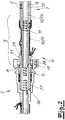
- a pipe 1 is shown, which is connected at its left pipe end 3 with a plug 4.
- the tube 1 comprises an inner tube 9 and two heating wires 2, which adjoin the inner tube 9 and are helically wound around the inner tube 9 in a double helical fashion.
- a contact element 10 comprising an adhesive tape 26 is wound around the heating wires 2 and the inner tube 9.
- a protective tube 15 encloses the arrangement of the inner tube 9, the heating wires 2 and the contact element 10, 26.
- the protective tube 15 is spaced from the adhesive tape 26, so that an insulating air jacket is located between the protective tube 15 and the adhesive tape 26.
- the plug 4 comprises a plug shank 5 and a housing 6, the housing 6 enclosing the pipe end 3.
- the plug shank 5 has for latching connection with a in Fig. 1 not shown connector 7 a locking means 8 in the form of a ring collar.
- a front end 29 of the plug shank is associated with the pipe end 3, whereas a front end 30 of the plug shank faces away from the pipe end.
- At the pipe end 3 associated front end 29 of the plug shank 5 is an engagement member 31st arranged in the form of a flange.
- the plug shank 5 has a sealing section 27 between the front end 30 facing away from the pipe end 3 and the latching means 8.
- the engagement element 31 of the plug shank 5 is in engagement with a complementary engagement element 18 in the form of a groove of the housing 6, whereby a high-tensile connection between the housing 6 and plug shank 5 is produced.
- the engagement element 18 is arranged in the vicinity of an end wall 19 of the housing 6 facing the connector 7.
- the housing 6 has two housing parts 16, wherein the sake of clarity in Fig. 1 only the lower housing part 16 is shown.
- the housing parts 16 are connected to each other by means of locking means 32.
- the inner tube 9 is connected to the plug shank 5 by insertion into a receptacle 17 of the plug shank 5 and subsequent laser beam welding or laser transmission welding.
- the plug shank 5 is therefore, like the inner tube 9, made of plastic and preferably made of polyamide.
- the plug shank 5 is colored black, but at the same time permeable to near-infrared or infrared radiation.
- the inner tube 9 is impermeable to the near-infrared or infrared radiation, so that a reliable weld is produced at the interface in the receptacle 17.
- the inner tube 9 projects beyond the pipe end 3, the protective tube 15, wherein the protective tube 15 with respect to the inner tube 9 and the tape 26 with the Heating wires 2 is sealed by means of a shrink tube 25 of the contact element 10.
- a shrink tube 25 of the contact element 10 surrounds the adhesive tape 26 of the contact element 10, wherein at the pipe end 3 both the tape 26 of the contact element 10 and the shrink tube 25 of the contact element 10 bring the heating wires 2 on the inner tube 9 to the plant.
- the heating wires 2 leave the inner tube 9 between the front end 29 of the plug shank 5 and the contact element 10, wherein the sake of simplicity in Fig. 1 only the upper heating wire 2 is shown.
- the upper heating wire 2 is folded into a plurality of windings of a loop-shaped portion 24 and finally runs into an electrical connection 21. There, the upper heating wire 2 is electrically connected to a PTC thermistor 22.
- the course of the lower heating wire 2 is analogous to the upper heating wire 2, but in Fig. 1 not apparent.
- the electrical connections 21 are fastened in a holder 12, wherein the holder 12 is in turn fastened to the shrink tube 25 at the tube end 3. Details of this attachment will be discussed below.
- the emerging from the housing 6 PTC thermistor 22 pass through a plug shaft 5 facing away from the front end 20 of the housing 6.
- the front end 20 of the housing 6 has for this purpose two recesses.
- the holder 12 and the electrical connections 21 are preferably arranged in a middle section 23 of the housing 6.
- the housing 6 or the central portion 23 is formed so that the holder 12 and the electrical connections 21 do not touch the housing.
- FIG. 2 the construction is off Fig. 1 shown in longitudinal section, for reasons of clarity on the representation of the housing 6, the holder 12 and the heating wires 2, the electrical connection 21 and the PTC thermistor 22 has been omitted.
- the receptacle 17 of the plug shank 5 can be seen, in which the inner tube 9 is inserted and abuts the end of the receptacle 17.
- the interaction of the plug shank with the connector 7 is shown.
- the connector 7 in the interior of a seal assembly comprising two sealing rings, which ensure a seal with the sealing portion 27 of the plug shank 5.
- a portion of a locking element is indicated on the lower, right side of the connector, which has two U-legs, not shown. These U-legs engage behind the latching means 8 of the plug shank 5 in the region of the latching section 28 of the plug shank 5, so that a latching connection is made possible.
- a heat-conducting element 11 is inserted in the form of a helical spring in the inner tube 9 at the pipe end 3.
- This heat-conducting element 11 extends into the sealing section 27 of the plug shank 5.
- the heating wires 2 generate, in particular via the loop-shaped sections 24 within the housing 6, a heating power density which exceeds the heating power density in the middle section of the tube 1.
- this heating power surplus also heats the heat-conducting element 11, which carries the heat into the plug shank 5 without any electrical connection. In this way, freezing is avoided, in particular within the sealing portion 27 of the plug shank 5.
- Fig. 3 the holder 12 is shown slightly enlarged at the end of the tube 3.
- the holder 12 includes a groove 33, in which the only hinted here pipe end 3 is engaged. Since the pipe end 3 is sheathed with the shrink tube 25, the groove 33 is suitably designed so that it the pipe end. 3 not only latching, but also permanently clamping and thus frictionally receives.
- the holder 12 in this embodiment comprises two receptacles 34 for each electrical connection 21.
- the receptacles 34 of the holder 12 are formed in this embodiment, a hollow cylinder and aligned parallel to the tube axis.
- the receptacles 34 of the holder 12 have openings which face the plug shank 5.
- the receptacles 34 of the holder 12 also have at their end facing away from the plug shank 5 each a stop 35, through which stop 35 a defined position of the electrical connections 21 is guaranteed.
- the holder 12 is as well as the plug shank 5 made of plastic and injection molded.
- the electrical connections 21 each include a shrink tube 36, which shrink tube 36 encloses a ferrule together with partial lengths of the heating wire 2 and the PTC thermistor 22.
- the ferrule produces an electrical contact of the heating wire 2 and the PTC thermistor 22.
- the electrical connections 21 are also provided with a relatively soft surface.
- the heating wire 2 comprises a strand 13 made of metal, preferably copper.
- the strand 13 is enclosed by a plastic coating 14, which in this embodiment comprises polyvinylidene fluoride (PVDF) and has a thickness of 0.2 mm.
- PVDF polyvinylidene fluoride
- the strand 13 has a diameter of 0.6 mm in this embodiment.
Landscapes
- Engineering & Computer Science (AREA)
- General Engineering & Computer Science (AREA)
- Chemical & Material Sciences (AREA)
- Mechanical Engineering (AREA)
- Chemical Kinetics & Catalysis (AREA)
- Health & Medical Sciences (AREA)
- Toxicology (AREA)
- Combustion & Propulsion (AREA)
- Resistance Heating (AREA)
- Pipe Accessories (AREA)
- Exhaust Gas After Treatment (AREA)
Abstract
Description
- Die Erfindung betrifft eine Rohrleitung für ein fluides Medium von Kraftfahrzeugen, insbesondere für eine wässrige Harnstofflösung, umfassend ein Rohr, wenigstens einen Heizdraht und einen an einem Rohrende des Rohres angeordneten Stecker, wobei der Stecker einen Steckerschaft und einen das Rohrende und den Heizdraht umschließendes Gehäuse aufweist, wobei der Steckerschaft ein Rastmittel, vorzugsweise einen Ringbund, zum Verrasten in einem Verbinder umfasst.
- Eine derartige Rohrleitung ist beispielsweise aus
EP 2 171 337 B1 bekannt. Das darin gezeigte Rohr weist ein Innenrohr sowie ein Anlageelement in Form eines Klebebandes auf, wobei das Anlageelement zwei doppelhelixförmig zueinander angeordnete Heizdrähte auf dem Innenrohr zur Anlage bringt. Die Anordnung aus Innenrohr, Heizdrähten und Anlageelement wird zudem noch von einem Schutzrohr in Form eines Wellrohres umschlossen. Das Gehäuse des Steckers umschließt das Anlageelement teilweise, wobei sich innerhalb des Gehäuses die Heizdrähte von dem Innenrohr lösen. Dort werden die Heizdrähte über elektrische Verbindungen mit einem weiteren Heizdraht des Steckerschaftes verbunden. Der Heizdraht des Steckerschaftes wird durch wendelförmige Nuten oder durch eine flächig ausgebildete Nut auf dem Steckerschaft wendelförmig geführt. Sowohl die wendelförmige Nut als auch die flächige Nut sind Ausrichtungselemente, welche der Führung des Heizdrahtes dienen. Zum Schutz des Heizdrahtes auf dem Steckerschaft erstreckt sich das Gehäuse vom Rohrende über die Ausrichtungselemente hinaus bis in die Spitze des Steckerschaftes. Beim Einstecken des Steckerschaftes in einen komplementären Verbinder entsteht auch ein axialer Überlapp zwischen dem Gehäuse des Steckerschaftes und dem Verbinder. Um eine Rastverbindung zwischen dem Verbinder und dem Stecker herzustellen, weist das Gehäuse des Steckerschaftes zudem Rastmittel auf, welche mit komplementären Rastmittel im Verbinder wechselwirken und so die Rastverbindung erzeugen. - Als nachteilig wird angesehen, dass der Heizdraht auf dem Steckerschaft angeordnet ist, was eine aufwendige Herstellung bedeutet. Außerdem besteht die Gefahr der Undichtigkeit, wenn das Gehäuse des Steckerschaftes beschädigt ist, weil dann die Rastmittel des Steckerschaftes aus den komplementären Rastmitteln des Verbinders herausrutschen können. Der Erfindung liegt daher die technische Aufgabe zugrunde, eine Rohrleitung mit Steckerschaft anzugeben, bei der der Herstellungsaufwand verringert ist und/oder wobei die Rastverbindung zwischen Stecker und Verbinder sicherer ausgebildet ist.
- Zur Lösung dieser Aufgabe lehrt die Erfindung eine Rohrleitung für ein fluides Medium von Kraftfahrzeugen, insbesondere für eine wässrige Harnstofflösung, umfassend ein Rohr, wenigstens einen Heizdraht und einen an einem Rohrende des Rohres angeordneten Stecker, wobei der Stecker einen Steckerschaft und ein das Rohrende und den Heizdraht umschließendes Gehäuse aufweist, wobei der Steckerschaft ein Rastmittel, vorzugsweise einen Ringbund, zum Verrasten in einem Verbinder umfasst,
wobei das Rohr ein Innenrohr und ein Anlageelement aufweist, wobei der Heizdraht zwischen dem Innenrohr und dem Anlageelement angeordnet ist, wobei das Anlageelement den Heizdraht auf dem Innenrohr zur Anlage bringt, wobei das Gehäuse das Anlageelement teilweise umschließt,
wobei ein erster Abschnitt des Heizdrahtes am Rohrende zwischen dem Anlageelement und dem Innenrohr verläuft und wobei ein zweiter Abschnitt des Heizdrahtes zwischen dem Anlageelement und dem Gehäuse verläuft. - Der Erfindung liegt die Erkenntnis zugrunde, dass durch den zusätzlichen Verlauf des Heizdrahtes zwischen Anlageelement und Gehäuse eine ausreichende Länge des Heizdrahtes im Gehäuse untergebracht werden kann, so dass der gesamte Stecker hinreichend erwärmt wird. Eine maschinell wie manuell aufwändige Wendelung ist am Steckerschaft dann nicht mehr erforderlich. Darüber hinaus bedarf es dann auch keiner weitreichenden Umschließung des Steckerschaftes durch das Gehäuse, so dass der Steckerschaft selbst das Rastmittel aufweisen kann. Da der Steckerschaft wesentlich kompakter als das Gehäuse ist und integral (aus einem Guss) ausgebildet sein kann, ist er deutlich stabiler und in der Folge ist auch eine entsprechend hergestellte Rastverbindung deutlich sicherer.
- Der Begriff "Innenrohr" meint insbesondere ein separates und vorzugsweise ein separat extrudiertes Rohrteil. Das Innenrohr kann aber auch ein innerer Wandabschnitt des separaten Rohrteiles sein. Der Ausdruck "Anlageelement" meint insbesondere ein Klebeband und/oder einen Schrumpfschlauch und/oder einen äußeren Wandabschnitt des separaten Rohrteils.
- Der Begriff "Rohrende" meint insbesondere den vom Gehäuse umschlossenen Abschnitt des Rohres einschließlich des dem Steckerschaft zugeordneten Stirnendes des Rohres. Der Ausdruck "Abschnitt" meint insbesondere einen Abschnitt axialer Ausrichtung. Der Begriff "axial" meint insbesondere die Achse des Steckerschaftes bzw. Rohres.
- Vorzugsweise ist der Steckerschaft ausgebildet, um in einen Verbinder fluiddicht eingesteckt zu werden. Zweckmäßigerweise ist die Außenseite des Steckerschaftes für Fluiddichtigkeit ausreichend glatt, um mit einem oder mehreren Dichtungsringen des Verbinders wechselwirken zu können. Es ist auch möglich, dass der Steckerschaft einen Dichtungsring bzw. Dichtungsringe aufweist, um mit einem auf seiner Innenseite entsprechend glatt ausgebildeten Verbinder fluiddicht wechselwirken zu können.
- Zweckmäßigerweise läuft der wenigstens eine Heizdraht entlang des Rohres auf den Stecker hinzu. Gemäß einer sehr bevorzugten Ausführungsform weist das Rohr zwei Heizdrähte auf, welche von dem Anlageelement umschlossen sind. Es ist vorteilhaft, die beiden Heizdrähte doppelhelixförmig am Innenrohr anzuordnen. Das Gehäuse hat zweckmäßigerweise eine dem Rohrende zugewandte Innenseite und eine Außenseite. Es ist bevorzugt, dass das Gehäuse wenigstens eine elektrische Verbindung umschließt.
- Vorteilhafterweise umfasst der Steckerschaft einen Dichtungsabschnitt und einen Rastabschnitt auf, wobei der Rastabschnitt dem Rohrende zugeordnet ist und wobei der Dichtungsabschnitt eine Dichtungsanordnung aufweist oder eine Dichtungsanordnung des Verbinders zugeordnet ist. Vorzugsweise sind der Dichtungsabschnitt und der Rastabschnitt durch das bzw. die Rastmittel des Steckerschaftes bzw. durch den Ringbund voneinander getrennt. Zweckmäßigerweise liegt der Rastabschnitt in axialer Richtung zwischen dem Dichtungsabschnitt und dem Anlageelement bzw. einem Schutzrohr. Bevorzugt weist der Steckerschaft ein dem Rohrende zugeordnetes Stirnende und ein dem Rohrende abgewandtes Stirnende auf. Der Begriff "Stirnende" meint insbesondere die ringförmigen Flächen in der Querschnittsebene an den beiden abschließenden Enden des Steckerschaftes. Der Steckerschaft weist zweckmäßigerweise eine Außenseite und eine Innenseite auf, wobei die Innenseite bevorzugt einen Kanal bildet, welcher Kanal die Stirnenden des Steckerschaftes zwecks Durchleitung des fluiden Mediums durch den Steckerschaft miteinander verbindet.
- Es ist sehr vorteilhaft, wenn der zweite Abschnitt des Heizdrahtes eine Länge aufweist, welche wenigstens um den Faktor 1,5, vorzugsweise wenigstens um den Faktor 2 und besonders vorzugsweise wenigstens um den Faktor 3 größer ist als die Ausdehnung des zweiten Abschnittes des Heizdrahtes in axialer Richtung. Der Ausdruck "axiale Richtung" meint insbesondere die Richtung der Rohrachse. Zweckmäßigerweise ist die Länge des zweiten Abschnittes des Heizdrahtes so bemessen, dass sie höchstens um den Faktor 20 bevorzugt höchstens um den Faktor 15 größer ist als die Ausdehnung des zweiten Abschnittes des Heizdrahtes in axialer Richtung. Gemäß einer bevorzugten Ausführungsform weist die Rohrleitung einen zweiten Heizdraht auf, wobei ein erster Abschnitt des zweiten Heizdrahtes am Rohrende zwischen dem Anlageelement und dem Innenrohr verläuft und wobei ein zweiter Abschnitt des zweiten Heizdrahtes zwischen dem Anlageelement und dem Gehäuse verläuft. Es ist zweckmäßig, wenn der zweite Abschnitt des zweiten Heizdrahtes bemessen ist wie der zweite Abschnitt des Heizdrahtes bzw. ersten Heizdrahtes. Es ist möglich, dass der zweite Abschnitt des Heizdrahtes bzw. ersten Heizdrahtes bzw. zweiten Heizdrahtes wenigstens einen schraubenlinienförmigen bzw. schleifenförmigen bzw. mäanderförmigen Teilabschnitt aufweist. Es ist bevorzugt, dass der Teilabschnitt bzw. die Teilabschnitte wenigstens eine, vorzugsweise aber mehrere Wicklungen umfasst bzw. umfassen. Die Wicklungen des Teilabschnittes bzw. der Teilabschnitte können zueinander koaxial ausgerichtet sein oder zueinander versetzt sein. Der Teilabschnitt bzw. die Teilabschnitte ist/sind zweckmäßigerweise von dem Gehäuse umschlossen und ist/sind bevorzugt zwischen dem Anlageelement und dem Gehäuse angeordnet.
- Gemäß einer besonders bevorzugten Ausführungsform ist der Steckerschaft und vorzugsweise der Stecker frei von in oder an dem Steckerschaft bzw. dem Stecker angeordneten Ausrichtungselementen zur Ausrichtung des Heizdrahtes. Der Begriff "Ausrichtungselement" meint insbesondere solche Elemente, welche nur der Ausrichtung des Heizdrahtes dienen, z. B. Nuten oder Stifte oder Vorsprünge auf der Außenseite des Steckerschaftes bzw. auf der Innenseite des Gehäuses. Der Begriff "Ausrichtungselemente" meint insbesondere keine solchen Elemente, welche den Heizdraht lediglich an den Steckerschaft bzw. das Rohrende bzw. an das Innenrohr bzw. an das Gehäuse andrücken, wie beispielsweise Klebebänder oder Schrumpfschläuche. Demzufolge sind die zylindrischen Wände des Rohrendes bzw. des Innenrohres bzw. des Anlageelementes keine Ausrichtungselemente im Sinne der Erfindung. Zwar können diese Wände den Heizdraht berühren und damit verformen und ausrichten, doch dienen diese zylindrischen Wände primär der Abdichtung und nicht ausschließlich der Ausrichtung des Heizdrahtes. Koaxiale zylindrische Wände sind daher bevorzugt keine Ausrichtungselemente im Sinne der Erfindung. Der Begriff "Ausrichtungselement" meint insbesondere solche Elemente, deren Wände auf der Außenseite des Steckerschaftes bzw. Rohrendes bzw. Gehäuses radial abstehen. Insbesondere sind Elemente, welche neben dem Heizdraht auch elektrische Verbindungen ausrichten keine Ausrichtungselemente zur Ausrichtung des Heizdrahtes.
- Es ist sehr bevorzugt, dass ein Wärmeleitelement im Inneren des Rohrendes angeordnet ist, welches Wärmeleitelement sich bis in den Steckerschaft und vorzugsweise bis in einen bzw. den Dichtungsabschnitt des Steckerschaftes hinein erstreckt. Die Rohrleitung ist vorzugsweise so ausgebildet, dass die Wärme des Heizdrahtes bzw. der Heizdrähte sich auf das Wärmeleitelement überträgt, so dass der Steckerschaft bzw. ein Kanal des Steckerschaftes über das Wärmeleitelement erwärmt wird. Das Wärmeleitelement ist vorzugsweise im Inneren des Innenrohrs angeordnet. Zweckmäßigerweise umschließt eine Innenseite des Innenrohrs das Wärmeleitelement entlang eines ersten axialen Abschnitts. Vorzugsweise umschließt der Steckerschaft und bevorzugt die Innenseite des Steckerschaftes das Wärmeleitelement entlang eines zweiten axialen Abschnittes. Es ist bevorzugt, dass die Innenseite des Innenrohrs in Kontakt steht mit dem Wärmeleitelement, wobei der Kontakt vorzugsweise ein Druckkontakt in vorzugsweise radialer Richtung ist. Zweckmäßigerweise ist das Wärmeleitelement so im Inneren des Rohrendes angeordnet, dass das Wärmeleitelement mit dem Fluid in Berührung bringbar ist. Vorteilhafterweise überlappen sich der Heizdraht bzw. die Heizdrähte und das Wärmeleitelement abschnittsweise in axialer Richtung. Es ist bevorzugt, dass der Überlapp zwischen dem Heizdraht bzw. den Heizdrähten und dem Wärmeleitelement berührungsfrei ist. Vorzugsweise ist der Heizdraht bzw. sind die Heizdrähte durch das Innenrohr von dem Wärmeleitelement getrennt. Zweckmäßigerweise umschließt der Heizdraht bzw. umschließen die Heizdrähte das Wärmeleitelement entlang eines axialen Abschnitts. Das Wärmeleitelement umfasst zweckmäßigerweise Metall oder einen wärmeleitfähigen Kunststoff und ist besonders bevorzugt als Schraubenfeder ausgebildet. Es ist bevorzugt, dass das Wärmeleitelement lediglich indirekt über den Heizdraht bzw. die Heizdrähte beheizt wird und insbesondere keine elektrischen Anschlüsse aufweist. In diesem Sinne ist das Wärmeleitelement zweckmäßigerweise ein passives Heizelement. Das Wärmeleitelement ist vorzugsweise zu wenigstens 20 %, weiter vorzugsweise zu wenigstens 25 % und besonders vorzugsweise zu wenigstens 30 % seiner Länge im Innenrohr angeordnet.
- Gemäß einer ganz besonders bevorzugten Ausführungsform überlappen sich der Heizdraht bzw. die Heizdrähte und der Steckerschaft nicht in axialer Richtung. Vorteilhafterweise läuft der auf den Stecker hinzulaufende Heizdraht bzw. die auf den Stecker hinzulaufenden Heizdrähte bis zu einem dem Rohrende zugeordneten Stirnende des Steckerschaftes, wobei der Heizdraht bzw. die Heizdrähte an dem dem Rohrende zugeordneten Stirnende des Steckerschaftes seine bzw. ihre Richtung ändert/n, so dass der Heizdraht bzw. die Heizdrähte ab diesem Stirnende des Steckerschaftes wenigstens eine Teilstrecke zurückläuft bzw. zurücklaufen. Vorzugsweise ist der Heizdraht bzw. sind die Heizdrähte lediglich am Rohr bzw. Rohrende befestigt, und ist/sind insbesondere nicht an dem Steckerschaft bzw. am Gehäuse befestigt. Es ist möglich, dass der Heizdraht bzw. die Heizdrähte mittelbar und insbesondere über eine elektrische Verbindung am Rohrende befestigt ist. Es ist sehr bevorzugt, dass eine elektrische Verbindung oder mehrere elektrische Verbindungen an dem Rohrende befestigt sind. Der Begriff "befestigt" meint insbesondere eine reversible Befestigung und insbesondere keinen unmittelbaren Kontakt. Es ist möglich, dass ein Abschnitt eines Halters zwischen dem Rohr und der elektrischen Verbindung bzw. den elektrischen Verbindungen angeordnet ist.
- Gemäß einer besonders vorteilhaften Ausführungsform umschließt das Gehäuse höchstens 70 %, vorzugsweise 50 % und besonders vorzugsweise höchstens 30 % der axialen Ausrichtung des Steckerschaftes. Es ist bevorzugt, dass das Gehäuse höchstens 40 %, weiter bevorzugt höchstens 20 % und ganz besonders bevorzugt höchstens 10 % der axialen Ausdehnung des Steckerschaftes umschließt. Gemäß einer ganz besonders bevorzugten Ausführungsform umschließt das Gehäuse lediglich ein Eingriffselement - vorzugsweise einen Flansch - des Steckerschaftes an einem dem Rohrende zugeordneten Stirnende des Steckerschaftes.
- Es ist sehr vorteilhaft, wenn das Gehäuse einen Halter zur Halterung des wenigstens einen Heizdrahtes bzw. wenigstens einer elektrischen Verbindung am Rohrende umschließt. Der Halter ist vorzugsweise separat von dem Steckerschaft bzw. dem Gehäuse bzw. dem Rohr ausgebildet. Der Halter ist vorzugsweise auf dem Rohrende aufrastbar und weiter vorzugsweise nach dem Aufrasten klemmend auf dem Rohrende angeordnet. Der Halter weist zweckmäßigerweise eine Nut für eine vorzugsweise rastende und besonders vorzugsweise rastende und klemmende Aufnahme des Rohrs bzw. des Rohrendes bzw. des Innenrohrs bzw. des Innenrohrs mit Anlageelement auf. Zweckmäßigerweise sitzt der Halter auf dem Anlageelement. Das Anlageelement umfasst vorzugsweise ein Klebeband und/oder einen Schrumpfschlauch am Rohrende. Vorzugsweise berührt der Halter den Schrumpfschlauch des Anlageelementes.
- Bevorzugterweise umfasst der Halter wenigstens eine Aufnahme und weiter vorzugsweise wenigstens zwei oder drei Aufnahmenuten für die Aufnahme einer elektrischen Verbindung bzw. mehrerer elektrischen Verbindungen. Die Aufnahme bzw. die Aufnahmen des Halters ist/sind zweckmäßigerweise hohlzylindrisch ausgebildet und bevorzugt parallel zur Rohrachse ausgerichtet. Die Öffnungen der Aufnahmen sind vorzugsweise dem Steckerschaft zugewandt. Die Aufnahme bzw. Aufnahmen umfasst/umfassen vorzugsweise jeweils einen in axialer Richtung wirkenden Anschlag, wobei der Anschlag bevorzugt an einem vom Steckerschaft abgewandten Stirnende der jeweiligen Aufnahme angeordnet ist. Die Aufnahme bzw. Aufnahmen sind vorteilhafterweise so ausgebildet, dass sie die elektrische Verbindung bzw. die elektrischen Verbindungen klemmend aufnimmt bzw. aufnehmen.
- Der Halter bzw. das Gehäuse sind besonders bevorzugt so ausgebildet, dass sie einander nicht berühren. Zweckmäßigerweise berühren die elektrische Verbindung bzw. die elektrischen Verbindungen und das Gehäuse einander nicht.
- Besonders vorzugsweise weist der Heizdraht eine Litze mit einer Kunststoffbeschichtung auf, wobei die Kunststoffbeschichtung vorzugsweise einen Fluorkunststoff umfasst. Der Fluorkunststoff ist vorzugsweise ein thermoplastischer Kunststoff und besonders vorzugsweise Polyvinylidenfluorid (PVDF). Die Kunststoffbeschichtung ist vorzugsweise wenigstens 0,05 mm, weiter vorzugsweise wenigstens 0,1 mm und besonders vorzugsweise wenigstens 0,12 mm stark. Zweckmäßigerweise ist die Kunststoffbeschichtung höchstens 1,0 mm, vorzugsweise 0,6 mm und besonders vorzugsweise höchstens 0,4 mm stark. Es ist sehr bevorzugt, dass die Litze durch die Kunststoffbeschichtung hindurch erkennbar ist. Die Litze umfasst zweckmäßigerweise einen oder mehrere Einzeldrähte und weist vorzugsweise Kupfer bzw. eine Kupfer-Nickel-Legierung auf. Die Litze ist zweckmäßigerweise wenigstens 0,3 mm, bevorzugt wenigstens 0,4 mm und besonders bevorzugt wenigstens 0,5 mm dick. Die Litze ist vorteilhafterweise höchstens 1,2 mm, weiter vorteilhafterweise höchstens 1,0 mm und besonders vorteilhafterweise höchstens 0,8 mm dick.
- Gemäß einer ersten, besonders bevorzugten Ausführungsform umfasst das Rohr ein Schutzrohr, wobei vorzugsweise das Schutzrohr gegenüber dem Innenrohr am Rohrende abgedichtet ist. Zweckmäßigerweise ist das Innenrohr ein separates, und vorzugsweise ein separat extrudiertes Rohrteil, welches Rohrteil von einem bevorzugt separat ausgebildeten Anlageelement umschlossen ist, welches Anlageelement bevorzugt von dem Schutzrohr umschlossen wird. Das Schutzrohr ist beispielsweise ein Wellrohr oder ein durchgängiges, entsprechend dickes rohrförmiges Element. Das Rohr kann aber auch ein einstückiges Bauteil sein, in welchem der Heizdraht bzw. die Heizdrähte eingebettet ist/sind. Der wenigstens eine Heizdraht steht zweckmäßigerweise nicht in Kontakt mit dem Fluidkanal des Rohres, weshalb das Innenrohr dieses einstückigen Bauteiles ein innerer Wandabschnitt des einstückigen Rohres ist, wobei der innere Wandabschnitt von dem Heizdraht bzw. den Heizdrähten umschlossen ist/sind. Ein äußerer Wandabschnitt des einstückigen Bauteiles umschließt den Heizdraht bzw. die Heizdrähte und bringt hierdurch den Heizdraht bzw. die Heizdrähte zur Anlage auf dem Innenrohr. Gemäß dieser Ausführungsform ist der äußere Wandabschnitt somit das Anlageelement.
- Vorteilhafterweise überragt das Innenrohr mit dem Heizdraht bzw. den Heizdrähten und vorzugsweise auch das Anlageelement in Form des Klebebandes das Schutzrohr. Bevorzugt wird das Schutzrohr mittels eines Schrumpfschlauches des Anlageelementes gegenüber dem Innenrohr abgedichtet. Vorzugsweise umschließt der Schrumpfschlauch des Anlageelementes einen Endabschnitt des Schutzrohres und einen Abschnitt des Innenrohres mit dem Heizdraht bzw. den Heizdrähten bzw. mit dem Klebeband. Am Rohrende umfasst das Anlageelement vorzugsweise ein bzw. das Klebeband und einen Schrumpfschlauch, wobei bevorzugt der Schrumpfschlauch das Klebeband umschließt. Es ist bevorzugt, dass das Gehäuse die Abdichtung bzw. den Schrumpfschlauch des Anlageelementes bzw. den das Schutzrohr überragenden Abschnitt des Innenrohrs vollständig umschließt.
- Es ist bevorzugt, dass das Gehäuse zwischen sich und dem Rohrende einen mit Luft gefüllten Raum einschließt. Ein mit Luft gefüllter Raum liegt insbesondere nicht bei Gehäusen vor, welche um das Rohrende umspritzt werden. Es ist zweckmäßig, dass sich der Heizdraht bzw. die Heizdrähte wenigstens abschnittsweise innerhalb des mit Luft gefüllten Raumes befinden. Vorteilhafterweise erstreckt sich der mit Luft gefüllte Raum von einem dem Steckerschaft zugeordnetem Stirnende des Gehäuses bis zu einem dem Steckerschaft abgewandten Stirnende des Gehäuses. Es ist bevorzugt, dass die elektrische Verbindung bzw. die elektrischen Verbindungen in dem mit Luft gefüllten Raum angeordnet sind. Zweckmäßigerweise ist wenigstens das Rohrende bzw. der Halter bzw. die Abdichtung bzw. der Schrumpfschlauch von dem mit Luft gefüllten Raum umschlossen. Insbesondere wird das Gehäuse nicht von einer Spritzgussfüllung - auch nicht abschnittsweise - ausgefüllt. Der mit Luft gefüllte Raum dient zweckmäßigerweise der Wärmeisolierung. Gemäß einer bevorzugten Ausführungsform umfasst das Gehäuse miteinander verbundene Gehäuseteile. Der Ausdruck "miteinander verbunden" meint insbesondere, dass die Gehäuseteile nicht ursprünglich miteinander verbunden waren, so dass nach der Verbindung das Gehäuse eine Verbindungsstelle bzw. Verbindungsstellen aufweist. Bei diesen Verbindungsstellen handelt es sich beispielsweise um Rastelemente, Schweißnähte oder dergleichen. Vorzugsweise umfasst das Gehäuse wenigstens zwei und besonders vorzugsweise lediglich zwei Gehäuseteile. Die Gehäuseteile sind vorzugsweise Gehäuseschalen und besonders vorzugsweise zwei Gehäusehalbschalen. Das Gehäuse ist zweckmäßigerweise so ausgebildet, dass es zwischen sich und dem Anschlussteil einen mit Luft gefüllten Raum einschließt.
- Vorzugsweise ist ein Abschnitt des Rohrendes bzw. des Innenrohrs in den Steckerschaft bzw. in eine Aufnahme des Steckerschaftes hineingesteckt. Die Aufnahme des Steckerschaftes umfasst bevorzugt einen Anschlag für das Rohrende bzw. das Innenrohr. Es ist bevorzugt, dass der Innendurchmesser der Aufnahme so bemessen ist, dass das Innenrohr in der Aufnahme eingeklemmt ist. Ganz besonders vorzugsweise wird das Innenrohr mit der Aufnahme mittels Laserdurchstrahlschweißen verbunden. Es ist zweckmäßig, dass der Steckerschaft und das Innenrohr schwarz gefärbt sind, wobei der Steckerschaft zugleich für Nahinfrarot- bzw. Nahinfrarotstrahlung transluzent ist. Das Innenrohr ist zweckmäßigerweise gegenüber Infrarot- bzw. Nahinfrarotstrahlung opak ausgebildet.
- Vorteilhafterweise weist das Gehäuse ein Eingriffselement zum Eingriff mit dem Steckerschaft auf, wobei das Eingriffselement des Gehäuses vorzugsweise an einem Stirnende des Gehäuses und besonders vorzugsweise an einem dem Verbinder zugewandten Stirnende des Gehäuses angeordnet ist. Das Eingriffselement des Gehäuses ist vorzugsweise eine Nut oder ein Flansch, wobei das Eingriffselement des Gehäuses zweckmäßigerweise in Eingriff steht mit einem Eingriffselement des Steckerschaftes. Das Eingriffselement des Steckerschaftes ist bevorzugt ein Flansch oder eine Nut und besonders bevorzugt ein Flansch. Das Eingriffselement des Steckerschaftes ist zweckmäßigerweise im Bereich des Rastabschnitts und vorzugsweise an einem dem Rohrende zugeordneten Stirnende des Steckerschaftes angeordnet. Das Gehäuse umfasst zweckmäßigerweise ein Halteelement zum Eingriff mit einem Schutzrohr, wobei das Halteelement vorzugsweise an einem dem Steckerschaft abgewandten Stirnende des Gehäuses angeordnet ist. Vorzugsweise ist das Halteelement des Gehäuses ein Flansch zum Eingreifen in das Schutzrohr.
- Es ist bevorzugt, dass das Gehäuse wenigstens eine elektrische Verbindung und vorzugsweise zwei oder drei elektrische Verbindungen zur Kontaktierung des Heizdrahtes mit einem Kaltleiter oder zur Kontaktierung zweier Heizdrahtabschnitte umschließt. Der wenigstens eine Kaltleiter führt vorzugsweise zu einer dem Stecker zugeordneten externen elektrischen Steckverbindung. Die elektrische Verbindung umfasst zweckmäßigerweise einen elektrischen Kontakt, beispielsweise eine Quetschhülse oder Lötverbindung, sowie bevorzugt einen Schrumpfschlauch. Unter dem Begriff "elektrische Verbindung" wird insbesondere nicht ein durchgängiger Heizdraht verstanden. Gemäß einer ersten Ausführungsform umschließt das Gehäuse lediglich eine elektrische Verbindung. In diesem Falle weist das Innenrohr bevorzugt lediglich einen Heizdraht auf, wobei dann der Heizdraht innerhalb des Gehäuses und innerhalb der elektrischen Verbindung mit einem Kaltleiter verbunden ist, welcher Kaltleiter aus dem Gehäuse herausgeführt ist. Gemäß einer zweiten Ausführungsform weist das Rohr zwei Heizdrähte auf, wobei die Heizdrähte innerhalb des Gehäuses in einer der beiden elektrischen Verbindungen mit jeweils einem Kaltleiter verbunden sind. Gemäß einer dritten Ausführungsform umschließt das Gehäuse drei elektrische Verbindungen. Gemäß dieser Ausführungsform umfasst das Rohr zwei Heizdrähte und der Stecker weist einen eigenen, separaten Heizdraht auf. In der ersten elektrischen Verbindung sind der erste Heizdraht des Rohres und das erste Ende des Heizdrahtes des Steckers miteinander verbunden. In der zweiten elektrischen Verbindung dieser Ausführungsform sind das zweite Ende des Heizdrahtes des ersten Steckers sowie ein erster Kaltleiter miteinander verbunden. In der dritten elektrischen Verbindung sind der zweite Heizdraht des Rohres sowie der zweite Kaltleiter miteinander verbunden. Gemäß einer vierten Ausführungsform weist der Stecker einen eigenen separaten Heizdraht auf und das Rohr umfasst zwei Heizdrähte. Der erste Heizdraht des Rohres ist mit dem ersten Ende des Heizdrahtes des Steckers über eine erste elektrische Verbindung verbunden, wohingegen der zweite Heizdraht des Rohres mit dem zweiten Ende des Heizdrahtes des Steckers über eine zweite elektrische Verbindung miteinander verbunden sind. Gemäß dieser Ausführungsform weist der Stecker keinen Kaltleiter auf. In der Folge umschließt das Gehäuse zwei elektrische Verbindungen. Gemäß einer fünften Ausführungsform umschließt das Gehäuse keine elektrische Verbindung, weil lediglich ein einziger durchgängiger Heizdraht vorliegt. Der durchgängige Heizdraht ist bevorzugt doppelhelixförmig auf dem Innenrohr angeordnet und endet zweckmäßigerweise in einer Schleife innerhalb des Gehäuses.
- Die Erfindung lehrt außerdem ein Verfahren zum Betrieb einer Rohrleitung für ein fluides Medium von Kraftfahrzeugen, insbesondere einer erfindungsgemäßen Rohrleitung, wobei die Rohrleitung ein Rohr, wenigstens ein Heizdraht und einen an einem Rohrende des Rohrs angeordneten Stecker umfasst, wobei der Stecker einen Steckerschaft und ein das Rohrende und den Heizdraht umschließendes Gehäuse aufweist, wobei der Steckerschaft ein Rastmittel, vorzugsweise einen Ringbund, zum Verrasten in einem Verbinder umfasst,
wobei das Rohr ein Innenrohr und ein Anlageelement aufweist, wobei der Heizdraht zwischen dem Innenrohr und dem Anlageelement angeordnet ist, wobei das Anlageelement den Heizdraht auf dem Innenrohr zur Anlage bringt, wobei das Gehäuse das Anlageelement teilweise umschließt,
wobei im Betrieb der Rohrleitung wenigstens eine Teillänge des Rohres und der Stecker mittels des ersten Abschnittes des Heizdrahtes mit einer ersten Heizleistung beaufschlagt werden und dass ein zweiter Abschnitt des Heizdrahtes zwischen dem Anlageelement und dem Gehäuse verläuft und den Stecker mit einer zweiten Heizleistung beaufschlägt. - Es ist besonders bevorzugt, dass die zweite Heizleistung des zweiten Abschnittes des Heizdrahtes wenigstens teilweise auf ein Wärmeleitelement, insbesondere ein erfindungsgemäßes Wärmeleitelement, übergeht. Besonders bevorzugt erwärmt das Wärmeleitelement den Steckerschaft von innen und erwärmt insbesondere einen Dichtungsabschnitt des Steckerschaftes von innen.
- Nachfolgend wird die Erfindung anhand einer lediglich ein Ausführungsbeispiel darstellenden Zeichnung detailliert erläutert. Es zeigen in schematischer Darstellung
- Figur 1
- eine erfindungsgemäße Rohrleitung in perspektivischer Darstellung mit geöffnetem Gehäuse,
- Figur 2
- die Rohrleitung aus
Figur 1 im Längsschnitt ohne Gehäuse, Halter, elektrische Verbindungen und den zwischen Anlageelement und Gehäuse befindlichen Heizdraht, - Figur 3
- einen Querschnitt von Gehäuse, Halter und Rohrende aus
Figur 1 und - Figur 4
- eine Querschnittsansicht des Heizdrahtes aus den
Figuren 1 bis 3 . - In
Fig. 1 ist ein Rohr 1 dargestellt, welches an seinem linken Rohrende 3 mit einem Stecker 4 verbunden ist. Das Rohr 1 umfasst ein Innenrohr 9 und zwei an dem Innenrohr 9 anliegende und doppelhelixförmig um das Innenrohr 9 gewundene Heizdrähte 2. Um die Heizdrähte 2 und das Innenrohr 9 ist ein Anlageelement 10 umfassend ein Klebeband 26 gewickelt. Ein Schutzrohr 15 umschließt die Anordnung aus dem Innenrohr 9, den Heizdrähte 2 und dem Anlageelement 10, 26. Zwecks Wärmeisolierung ist das Schutzrohr 15 von dem Klebeband 26 beabstandet, so dass ein isolierender Luftmantel sich zwischen dem Schutzrohr 15 und dem Klebeband 26 befindet. - Der Stecker 4 umfasst einen Steckerschaft 5 und ein Gehäuse 6, wobei das Gehäuse 6 das Rohrende 3 umschließt. Der Steckerschaft 5 weist zum rastenden Verbinden mit einem in
Fig. 1 nicht dargestellten Verbinder 7 ein Rastmittel 8 in Form eines Ringbundes auf. Ein Stirnende 29 des Steckerschaftes ist dem Rohrende 3 zugeordnet, wohingegen ein Stirnende 30 des Steckerschaftes von dem Rohrende abgewandt ist. An dem dem Rohrende 3 zugeordneten Stirnende 29 des Steckerschaftes 5 ist ein Eingriffselement 31 in Form eines Flansches angeordnet. Der Steckerschaft 5 weist einen Dichtungsabschnitt 27 zwischen dem dem Rohrende 3 abgewandten Stirnende 30 und dem Rastmittel 8 auf. Zwischen dem Rastmittel 8 und dem dem Rohrende 3 zugeordneten Stirnende 29 befindet sich ein Rastabschnitt 28 des Steckerschaftes 5. Das dem Rohrende 3 abgewandte Stirnende 30 des Steckerschaftes 5 ist zwecks erleichtertem Einstecken in den Verbinder 7 verjüngt. - Das Eingriffselement 31 des Steckerschaftes 5 steht in Eingriff mit einem komplementären Eingriffselement 18 in Form einer Nut des Gehäuses 6, wodurch eine zugfeste Verbindung zwischen Gehäuse 6 und Steckerschaft 5 hergestellt wird. Das Eingriffselement 18 ist in der Nähe einer dem Verbinder 7 zugewandten Stirnwand 19 des Gehäuses 6 angeordnet. Das Gehäuse 6 weist zwei Gehäuseteile 16 auf, wobei der Übersichtlichkeit halber in
Fig. 1 lediglich das untere Gehäuseteil 16 abgebildet ist. Die Gehäuseteile 16 werden mittels Rastmitteln 32 miteinander verbunden. - Demgegenüber wird das Innenrohr 9 mit dem Steckerschaft 5 durch Einstecken in eine Aufnahme 17 des Steckerschaftes 5 und anschließendes Laserstrahlschweißen bzw. Laserdurchstrahlschweißen miteinander verbunden. Der Steckerschaft 5 ist daher, wie auch das Innenrohr 9, aus Kunststoff und vorzugsweise aus Polyamid gefertigt. Der Steckerschaft 5 ist schwarz gefärbt, jedoch gleichzeitig für Nahinfrarot- bzw. Infrarotstrahlung durchlässig. Demgegenüber ist das Innenrohr 9 für die Nahinfrarot- bzw. Infrarotstrahlung undurchlässig, so dass an der Grenzfläche in der Aufnahme 17 eine zuverlässige Schweißnaht entsteht.
- Das Innenrohr 9 überragt am Rohrende 3 das Schutzrohr 15, wobei das Schutzrohr 15 gegenüber dem Innenrohr 9 bzw. dem Klebeband 26 mit den Heizdrähten 2 mittels eines Schrumpfschlauches 25 des Anlageelementes 10 abgedichtet ist. Am Rohrende 3 umschließt der Schrumpfschlauch 25 des Anlageelementes 10 das Klebeband 26 des Anlageelementes 10, wobei auch am Rohrende 3 sowohl das Klebeband 26 des Anlageelementes 10 als auch der Schrumpfschlauch 25 des Anlageelementes 10 die Heizdrähte 2 auf dem Innenrohr 9 zur Anlage bringen.
- Die Heizdrähte 2 verlassen das Innenrohr 9 zwischen dem Stirnende 29 des Steckerschaftes 5 und dem Anlageelement 10, wobei der Einfachheit halber in
Fig. 1 lediglich der obere Heizdraht 2 abgebildet ist. Der obere Heizdraht 2 ist zu mehreren Wicklungen eines schleifenförmigen Abschnittes 24 zusammengelegt und läuft schließlich in eine elektrische Verbindung 21 hinein. Dort wird der obere Heizdraht 2 mit einem Kaltleiter 22 elektrisch verbunden. Der Verlauf des unteren Heizdrahtes 2 ist analog zu dem oberen Heizdraht 2, jedoch inFig. 1 nicht ersichtlich. - Die elektrischen Verbindungen 21 sind in einem Halter 12 befestigt, wobei der Halter 12 wiederum auf dem Schrumpfschlauch 25 am Rohrende 3 befestigt ist. Auf Einzelheiten dieser Befestigung wird nachfolgend noch eingegangen. Die Aus den Gehäuse 6 heraustretenden Kaltleiter 22 durchlaufen ein dem Steckerschaft 5 abgewandtes Stirnende 20 des Gehäuses 6. Das Stirnende 20 des Gehäuses 6 weist hierzu zwei Ausnehmungen auf. Der Halter 12 und die elektrischen Verbindungen 21 sind bevorzugt in einem Mittelabschnitt 23 des Gehäuses 6 angeordnet. Das Gehäuse 6 bzw. der Mittelabschnitt 23 ist so ausgebildet, dass der Halter 12 bzw. die elektrischen Verbindungen 21 das Gehäuse nicht berühren.
- In
Fig. 2 ist der Aufbau ausFig. 1 im Längsschnitt abgebildet, wobei aus Gründen der Übersichtlichkeit auf die Darstellung des Gehäuses 6, des Halters 12 sowie der Heizdrähte 2, der elektrischen Verbindung 21 und der Kaltleiter 22 verzichtet wurde. In dieser Figur ist die Aufnahme 17 des Steckerschaftes 5 zu erkennen, in welche das Innenrohr 9 eingesteckt ist und am Ende der Aufnahme 17 anschlägt. Darüber hinaus ist inFig. 2 die Wechselwirkung des Steckerschaftes mit dem Verbinder 7 dargestellt. So weist der Verbinder 7 im Inneren eine Dichtungsanordnung umfassend zwei Dichtungsringe auf, welche mit dem Dichtungsabschnitt 27 des Steckerschaftes 5 eine Abdichtung gewährleisten. Außerdem ist auf der unteren, rechten Seite des Verbinders ein Teilabschnitt eines Rastelementes angedeutet, welches zwei nicht dargestellte U-Schenkel aufweist. Diese U-Schenkel hintergreifen das Rastmittel 8 des Steckerschaftes 5 im Bereich des Rastabschnittes 28 des Steckerschaftes 5, so dass eine Rastverbindung ermöglicht ist. - Schließlich geht aus
Fig. 2 hervor, dass ein Wärmeleitelement 11 in Form einer Schraubenfeder in das Innenrohr 9 am Rohrende 3 eingesteckt ist. Dieses Wärmeleitelement 11 erstreckt sich bis in den Dichtungsabschnitt 27 des Steckerschaftes 5 hinein. Dabei erzeugen die Heizdrähte 2 insbesondere über die schleifenförmigen Abschnitte 24 innerhalb des Gehäuses 6 eine Heizleistungsdichte, welche über die Heizleistungsdichte im Mittelabschnitt des Rohres 1 hinausgeht. Dieser Heizleistungsüberschuss erwärmt zugleich auch das Wärmeleitelement 11, welches die Wärme ohne jegliche elektrische Verbindung in den Steckerschaft 5 hineinträgt. Auf diese Weise wird ein Gefrieren insbesondere innerhalb des Dichtungsabschnittes 27 des Steckerschaftes 5 vermieden. - In
Fig. 3 ist der Halter 12 am Rohrende 3 etwas vergrößert dargestellt. Der Halter 12 umfasst eine Nut 33, in welche das hier nur angedeutete Rohrende 3 eingerastet wird. Da das Rohrende 3 mit dem Schrumpfschlauch 25 ummantelt ist, ist die Nut 33 zweckmäßigerweise so ausgebildet, dass sie das Rohrende 3 nicht nur rastend, sondern auch dauerhaft klemmend und damit kraftschlüssig aufnimmt. Darüber hinaus umfasst der Halter 12 in diesem Ausführungsbeispiel zwei Aufnahmen 34 für je eine elektrische Verbindung 21. Die Aufnahmen 34 des Halters 12 sind in diesem Ausführungsbeispiel hohlzylindrisch ausgebildet und parallel zur Rohrachse ausgerichtet. Die Aufnahmen 34 des Halters 12 weisen Öffnungen auf, welche, dem Steckerschaft 5 zugewandt sind.. Die Aufnahmen 34 der Halterung 12 weisen außerdem an ihren dem Steckerschaft 5 abgewandten Ende je einen Anschlag 35 auf, durch welchen Anschlag 35 eine definierte Position der elektrischen Verbindungen 21 gewährleistet wird. Der Halter 12 ist wie auch der Steckerschaft 5 aus Kunststoff und mittels Spritzguss gebildet. - Die elektrischen Verbindungen 21 umfassen jeweils einen Schrumpfschlauch 36, welcher Schrumpfschlauch 36 eine Quetschhülse nebst Teillängen des Heizdrahtes 2 bzw. des Kaltleiters 22 umschließt. Die Quetschhülse erzeugt eine elektrische Kontaktierung von dem Heizdraht 2 und dem Kaltleiter 22. Durch den Schrumpfschlauch 36 sind die elektrischen Verbindungen 21 ebenfalls mit einer verhältnismäßig weichen Oberfläche versehen. Durch ein kraftschlüssiges Einschieben der elektrischen Verbindungen 21 in die Öffnungen der Aufnahmen 34 des Halters 12 werden, die elektrischen Verbindungen 21 vorteilhafterweise dauerhaft klemmend von den Aufnahmen 34 aufgenommen.
- In der
Fig. 4 schließlich ist ein Querschnitt des Heizdrahtes 2 zu erkennen. Der Heizdraht 2 umfasst eine Litze 13 aus Metall, vorzugsweise aus Kupfer. Die Litze 13 wird von einer Kunststoffbeschichtung 14 umschlossen, welche in diesem Ausführungsbeispiel Polyvinylidenfluorid (PVDF) umfasst und eine Dicke von 0,2 mm aufweist. Die Litze 13 hat in diesem Ausführungsbeispiel einen Durchmesser von 0,6 mm.
Claims (15)
- Rohrleitung für ein fluides Medium von Kraftfahrzeugen, insbesondere für eine wässrige Harnstofflösung, umfassend ein Rohr (1), wenigstens einen Heizdraht (2) und einen an einem Rohrende (3) des Rohres (1) angeordneten Stecker (4), wobei der Stecker (4) einen Steckerschaft (5) und ein das Rohrende (3) und den Heizdraht (2) umschließendes Gehäuse (6) aufweist, wobei der Steckerschaft (5) ein Rastmittel (8), vorzugsweise einen Ringbund, zum Verrasten in einem Verbinder (7) umfasst,
wobei das Rohr (1) ein Innenrohr (9) und ein Anlageelement (10) aufweist, wobei der Heizdraht (2) zwischen dem Innenrohr (9) und dem Anlageelement (10) angeordnet ist, wobei das Anlageelement (10) den Heizdraht (2) auf dem Innenrohr (9) zur Anlage bringt, wobei das Gehäuse das Anlageelement (10) teilweise umschließt,
dadurch gekennzeichnet , dass
ein erster Abschnitt des Heizdrahtes (2) am Rohrende (3) zwischen dem Anlageelement (10) und dem Innenrohr (9) verläuft und wobei ein zweiter Abschnitt des Heizdrahtes (2) zwischen dem Anlageelement (10) und dem Gehäuse (6) verläuft. - Rohrleitung nach Anspruch 1, wobei der zweite Abschnitt des Heizdrahtes (2) eine Länge aufweist, welche wenigstens um den Faktor 1,5, vorzugsweise um den Faktor 2 und besonders vorzugsweise wenigstens um den Faktor 3 größer ist als die Ausdehnung des zweiten Abschnittes des Heizdrahtes (2) in axialer Richtung.
- Rohrleitung nach Anspruch 1 oder 2, wobei der Steckerschaft (5) und vorzugsweise der Stecker (4) frei von in oder an dem Steckerschaft (5) bzw. Stecker (4) angeordneten Ausrichtungselementen zur Ausrichtung des Heizdrahtes (2) ist.
- Rohrleitung nach einem der Ansprüche 1 bis 3, wobei ein Wärmeleitelement (11) im Inneren des Rohrendes (3) angeordnet ist, welches Wärmeleitelement (11) sich bis in den Steckerschaft (5) und vorzugsweise bis in einen bzw. den Dichtungsabschnitt (27) des Steckerschaftes (5) hinein erstreckt.
- Rohrleitung nach einem der Ansprüche 1 bis 4, wobei der Heizdraht (2) und der Steckerschaft (5) sich nicht in axialer Richtung überlappen.
- Rohrleitung nach einem der Ansprüche 1 bis 5, wobei das Gehäuse (6) höchstens 70 %, vorzugsweise höchstens 50 % und besonders vorzugsweise höchstens 30 % der axialen Ausdehnung des Steckerschaftes (5) umschließt.
- Rohrleitung nach einem der Ansprüche 1 bis 6, wobei das Gehäuse (6) einen Halter (12) zur Halterung des wenigstens einen Heizdrahtes (2) bzw. wenigstens einer elektrischen Verbindung (21) am Rohrende (3) umschließt.
- Rohrleitung nach einem der Ansprüche 1 bis 7, wobei der Heizdraht (2) eine Litze (13) mit einer Kunststoffbeschichtung (14) aufweist, wobei die Kunststoffbeschichtung (14) vorzugsweise einen Fluorkunststoff umfasst.
- Rohrleitung nach einem der Ansprüche 1 bis 8, wobei das Rohr (1) ein Schutzrohr (15) umfasst, wobei vorzugsweise das Schutzrohr (15) gegenüber dem Innenrohr (9) am Rohrende (3) abgedichtet ist.
- Rohrleitung nach einem der Ansprüche 1 bis 9, wobei das Gehäuse (6) zwischen sich und dem Rohrende (3) einen mit Luft gefüllten Raum einschließt.
- Rohrleitung nach einem der Ansprüche 7 bis 10, wobei das Gehäuse (6) und der Halter (12) so ausgebildet sind, dass sie einander nicht berühren.
- Rohrleitung nach einem der Ansprüche 1 bis 11, wobei ein Abschnitt des Rohrendes (3) bzw. des Innenrohrs (9) in den Steckerschaft (5) bzw. in einer Aufnahme (17) des Steckerschaftes (5) hineingesteckt ist.
- Rohrleitung nach einem der Ansprüche 1 bis 13, wobei das Gehäuse (6) wenigstens eine elektrische Verbindung (21) und vorzugsweise zwei oder drei elektrische Verbindungen (21) zur Kontaktierung des Heizdrahtes (2) mit einem Kaltleiter (22) oder zur Kontaktierung zweier Heizdrahtabschnitte umschließt.
- Rohrleitung nach einem der Ansprüche 7 bis 13, wobei der Halter (12) wenigstens eine und vorzugsweise zwei oder drei Aufnahmen (34) zur Aufnahme hier einer elektrischen Verbindung (21) aufweist, wobei die Aufnahme (34) bzw. Aufnahmen (34) bevorzugt hohlzylindrisch ausgebildet ist/sind.
- Verfahren zum Betrieb einer Rohrleitung für ein fluides Medium von Kraftfahrzeugen, insbesondere einer Rohrleitung gemäß einem der Ansprüche 1 bis 14, wobei die Rohrleitung ein Rohr (1), wenigstens einen Heizdraht (2) und einen an einem Rohrende (3) des Rohrs (1) angeordneten Stecker (4) umfasst, wobei der Stecker (4) einen Steckerschaft (5) und ein das Rohrende (3) und den Heizdraht (2) umschließendes Gehäuse (6) aufweist, wobei der Steckerschaft (5) ein Rastmittel (8), vorzugsweise einen Ringbund, zum Verrasten in einem Verbinder (7) umfasst,
wobei das Rohr (1) ein Innenrohr (9) und ein Anlageelement (10) aufweist, wobei der Heizdraht (2) zwischen dem Innenrohr (9) und dem Anlageelement (10) angeordnet ist, wobei das Anlageelement (10) den Heizdraht (2) auf dem Innenrohr (9) zur Anlage bringt, wobei das Gehäuse (6) das Anlageelement (10) teilweise umschließt,
dadurch gekennzeichnet, dass
im Betrieb der Rohrleitung wenigstens eine Teillänge des Rohres (1) und der Stecker (4) mittels des ersten Abschnittes des Heizdrahtes (2) mit einer ersten Heizleistung beaufschlagt werden,
und dass ein zweiter Abschnitt des Heizdrahtes (2) zwischen dem Anlageelement (10) und dem Gehäuse (6) verläuft und den Stecker (4) mit einer zweiten Heizleistung beaufschlägt.
Priority Applications (7)
| Application Number | Priority Date | Filing Date | Title |
|---|---|---|---|
| EP17163623.6A EP3382254B1 (de) | 2017-03-29 | 2017-03-29 | Beheizte rohrleitung mit stecker sowie ein verfahren zum betrieb dieser rohrleitung |
| CN201880036343.XA CN110691938B (zh) | 2017-03-29 | 2018-03-29 | 具有插塞的加热管系统及操作其的方法 |
| US16/496,808 US11168598B2 (en) | 2017-03-29 | 2018-03-29 | Heated tubing with plug, and a method for operating this tubing |
| PCT/IB2018/052157 WO2018178909A1 (en) | 2017-03-29 | 2018-03-29 | Heated tubing with plug, and a method for operating this tubing |
| JP2019553261A JP6987880B2 (ja) | 2017-03-29 | 2018-03-29 | プラグ付き被加熱導管およびこの導管の動作方法 |
| KR1020197032072A KR102513812B1 (ko) | 2017-03-29 | 2018-03-29 | 플러그를 구비한 가열 배관, 및 이 배관을 동작시키는 방법 |
| MX2019011628A MX2019011628A (es) | 2017-03-29 | 2018-03-29 | Tuberia caliente con enchufe, y metodo para operar esta tuberia. |
Applications Claiming Priority (1)
| Application Number | Priority Date | Filing Date | Title |
|---|---|---|---|
| EP17163623.6A EP3382254B1 (de) | 2017-03-29 | 2017-03-29 | Beheizte rohrleitung mit stecker sowie ein verfahren zum betrieb dieser rohrleitung |
Publications (2)
| Publication Number | Publication Date |
|---|---|
| EP3382254A1 true EP3382254A1 (de) | 2018-10-03 |
| EP3382254B1 EP3382254B1 (de) | 2020-06-03 |
Family
ID=58454971
Family Applications (1)
| Application Number | Title | Priority Date | Filing Date |
|---|---|---|---|
| EP17163623.6A Active EP3382254B1 (de) | 2017-03-29 | 2017-03-29 | Beheizte rohrleitung mit stecker sowie ein verfahren zum betrieb dieser rohrleitung |
Country Status (7)
| Country | Link |
|---|---|
| US (1) | US11168598B2 (de) |
| EP (1) | EP3382254B1 (de) |
| JP (1) | JP6987880B2 (de) |
| KR (1) | KR102513812B1 (de) |
| CN (1) | CN110691938B (de) |
| MX (1) | MX2019011628A (de) |
| WO (1) | WO2018178909A1 (de) |
Cited By (1)
| Publication number | Priority date | Publication date | Assignee | Title |
|---|---|---|---|---|
| WO2021175618A1 (de) * | 2020-03-06 | 2021-09-10 | Eugen Forschner Gmbh | Heizschlauch-wellrohr-verbindung |
Citations (5)
| Publication number | Priority date | Publication date | Assignee | Title |
|---|---|---|---|---|
| WO2008131993A1 (de) * | 2007-04-26 | 2008-11-06 | Voss Automotive Gmbh | Leitungsverbinder für medienleitungen |
| DE202008013048U1 (de) * | 2008-10-02 | 2009-03-05 | Eugen Forschner Gmbh | Mediumkupplung mit elektrischem Anschluss |
| EP2171337B1 (de) | 2007-07-26 | 2011-11-02 | Voss Automotive GmbH | Konfektionierte medienleitung |
| EP2420715A2 (de) * | 2010-08-20 | 2012-02-22 | Voss Automotive GmbH | Isolations- und/oder Schutzabdeckung für beheizbare Leitungsverbinder |
| DE102012020055A1 (de) * | 2012-10-12 | 2014-04-17 | Voss Automotive Gmbh | Elektrisch beheizbare Medienleitung sowie Verfahren zum Herstellen einer solchen |
Family Cites Families (14)
| Publication number | Priority date | Publication date | Assignee | Title |
|---|---|---|---|---|
| US5379742A (en) * | 1993-04-19 | 1995-01-10 | Breland; Bura B. | Vaporized fuel injection system |
| SE529417C2 (sv) * | 2005-12-22 | 2007-08-07 | Volvo Lastvagnar Ab | Ledningsnät för ett fordon |
| WO2007131993A1 (en) * | 2006-05-15 | 2007-11-22 | Solvay Fluor Gmbh | Flux for brazing of aluminium |
| DE102006060314A1 (de) * | 2006-12-20 | 2008-06-26 | Robert Bosch Gmbh | Vorrichtung zum Befördern fluider Medien bei tiefen Temperaturen |
| DE202007009588U1 (de) * | 2007-04-26 | 2008-09-04 | Voss Automotive Gmbh | Leitungsverbinder für Medienleitungen |
| FR2924786A1 (fr) | 2007-12-11 | 2009-06-12 | Coutier Moulage Gen Ind | Canalisation chauffante pour le transport de fluide |
| DE202007018089U1 (de) * | 2007-12-21 | 2009-05-07 | Voss Automotive Gmbh | Beheizbare Medienleitung |
| DE202009012230U1 (de) | 2009-06-23 | 2010-11-04 | Voss Automotive Gmbh | Elektrisch beheizbare Medienleitung sowie Leitungsverbinder |
| KR101838306B1 (ko) * | 2010-01-08 | 2018-03-13 | 파커-한니핀 코포레이션 | 선택적 촉매 환원(scr) 시스템을 위한 전기 가열식 호스 조립체 |
| CN103998845B (zh) | 2011-10-14 | 2017-11-03 | 福士汽车配套部件责任有限公司 | 用于可加热的介质管道的可至少部分加热的管道连接器和具有该管道连接器的组装介质管道 |
| JP6131277B2 (ja) * | 2012-02-28 | 2017-05-17 | ノーマ・ユー・エス・ホールディング・リミテッド・ライアビリティ・カンパニーNorma U. S. Holding Llc | 自動車選択的接触還元(scr)システムのセンサ保持部およびアセンブリ |
| DE102012101690B4 (de) * | 2012-03-01 | 2014-03-27 | Phoenix Contact Gmbh & Co. Kg | Steckverbinder, Steckverbinderanordnung, Ladeeinrichtung und Elektrofahrzeug |
| EP3211190B1 (de) * | 2016-02-23 | 2019-04-17 | TI Automotive (Fuldabrück) GmbH | Verbinderanordnung mit zumindest einem verbinder und zumindest einer medienleitung |
| US10508577B2 (en) * | 2017-11-27 | 2019-12-17 | Voss Automotive Gmbh | Line connector with integrated sensor for measurement of urea solutions |
-
2017
- 2017-03-29 EP EP17163623.6A patent/EP3382254B1/de active Active
-
2018
- 2018-03-29 MX MX2019011628A patent/MX2019011628A/es unknown
- 2018-03-29 WO PCT/IB2018/052157 patent/WO2018178909A1/en not_active Ceased
- 2018-03-29 JP JP2019553261A patent/JP6987880B2/ja active Active
- 2018-03-29 US US16/496,808 patent/US11168598B2/en active Active
- 2018-03-29 KR KR1020197032072A patent/KR102513812B1/ko active Active
- 2018-03-29 CN CN201880036343.XA patent/CN110691938B/zh active Active
Patent Citations (5)
| Publication number | Priority date | Publication date | Assignee | Title |
|---|---|---|---|---|
| WO2008131993A1 (de) * | 2007-04-26 | 2008-11-06 | Voss Automotive Gmbh | Leitungsverbinder für medienleitungen |
| EP2171337B1 (de) | 2007-07-26 | 2011-11-02 | Voss Automotive GmbH | Konfektionierte medienleitung |
| DE202008013048U1 (de) * | 2008-10-02 | 2009-03-05 | Eugen Forschner Gmbh | Mediumkupplung mit elektrischem Anschluss |
| EP2420715A2 (de) * | 2010-08-20 | 2012-02-22 | Voss Automotive GmbH | Isolations- und/oder Schutzabdeckung für beheizbare Leitungsverbinder |
| DE102012020055A1 (de) * | 2012-10-12 | 2014-04-17 | Voss Automotive Gmbh | Elektrisch beheizbare Medienleitung sowie Verfahren zum Herstellen einer solchen |
Cited By (1)
| Publication number | Priority date | Publication date | Assignee | Title |
|---|---|---|---|---|
| WO2021175618A1 (de) * | 2020-03-06 | 2021-09-10 | Eugen Forschner Gmbh | Heizschlauch-wellrohr-verbindung |
Also Published As
| Publication number | Publication date |
|---|---|
| US11168598B2 (en) | 2021-11-09 |
| JP2020515787A (ja) | 2020-05-28 |
| CN110691938B (zh) | 2022-01-11 |
| KR20190127961A (ko) | 2019-11-13 |
| US20210102485A1 (en) | 2021-04-08 |
| KR102513812B1 (ko) | 2023-03-24 |
| JP6987880B2 (ja) | 2022-01-05 |
| MX2019011628A (es) | 2019-11-18 |
| WO2018178909A1 (en) | 2018-10-04 |
| CN110691938A (zh) | 2020-01-14 |
| EP3382254B1 (de) | 2020-06-03 |
Similar Documents
| Publication | Publication Date | Title |
|---|---|---|
| EP2171337B9 (de) | Konfektionierte medienleitung | |
| EP2641006B1 (de) | Konfektionierte elektrisch beheizbare medienleitung sowie verfahren zum herstellen einer solchen medienleitung | |
| EP2220419B1 (de) | Beheizbare medienleitung | |
| EP2347163B1 (de) | Leitungsverbinder für medienleitungen | |
| EP2788692B1 (de) | Konfektionierte beheizbare medienleitung mit einer medienleitung mit zumindest zwei auf deren aussenseite angeordneten heizelementen und verfahren zu ihrer herstellung | |
| EP2766651B1 (de) | Konfektionierte medienleitung mit zumindest einer beheizbaren medienleitung und mit zumindest einem zumindest teilweise beheizbaren leitungsverbinder | |
| EP2706280B1 (de) | Steckverbinder | |
| DE10333206B4 (de) | Elektrische Heizpatrone für zylindrische Körper | |
| DE2406236C2 (de) | Verbindungselement für koaxiale Paare von Nachrichtenkabeln | |
| DE202007010865U1 (de) | Elektrische Heizpatrone | |
| EP3211190B1 (de) | Verbinderanordnung mit zumindest einem verbinder und zumindest einer medienleitung | |
| WO1979000961A1 (fr) | Manchon a souder en matiere thermoplastique | |
| EP2788646B2 (de) | Konfektionierte medienleitung und verfahren zum konfektionieren einer medienleitung mit innenliegenden heizelementen | |
| WO2016087054A2 (de) | Beheizungssystem für eine fluidführende leitung | |
| EP3382255B1 (de) | Rohrleitung umfassend einen verbinder sowie verfahren zum betrieb dieser rohrleitung | |
| DE102016113493A1 (de) | Leitungsverbinder und Verfahren zum Herstellen eines Leitungsverbinders | |
| EP3382254B1 (de) | Beheizte rohrleitung mit stecker sowie ein verfahren zum betrieb dieser rohrleitung | |
| EP1747790B2 (de) | Vorrichtung zum Temperieren einer Fluidleitung | |
| EP3652477B1 (de) | Rohrleitungselement mit einer integrierten heiz- und/oder kühlvorrichtung und verfahren zu seiner herstellung | |
| DE202014103393U1 (de) | Verbinder und Verbinderaggregat aus Verbinder und Rohrleitung | |
| DE102022117668A1 (de) | Schlauch zum Beheizen eines Fluids und Schlauchanordnung | |
| EP3737885B1 (de) | Konfektionierte fluidleitung | |
| DE202010010779U1 (de) | Durchlauferhitzer | |
| WO2018091570A1 (de) | Steckverbinder | |
| EP3130441B1 (de) | Verbinder und verfahren zur herstellung eines verbinders |
Legal Events
| Date | Code | Title | Description |
|---|---|---|---|
| PUAI | Public reference made under article 153(3) epc to a published international application that has entered the european phase |
Free format text: ORIGINAL CODE: 0009012 |
|
| STAA | Information on the status of an ep patent application or granted ep patent |
Free format text: STATUS: REQUEST FOR EXAMINATION WAS MADE |
|
| 17P | Request for examination filed |
Effective date: 20180320 |
|
| AK | Designated contracting states |
Kind code of ref document: A1 Designated state(s): AL AT BE BG CH CY CZ DE DK EE ES FI FR GB GR HR HU IE IS IT LI LT LU LV MC MK MT NL NO PL PT RO RS SE SI SK SM TR |
|
| AX | Request for extension of the european patent |
Extension state: BA ME |
|
| STAA | Information on the status of an ep patent application or granted ep patent |
Free format text: STATUS: EXAMINATION IS IN PROGRESS |
|
| 17Q | First examination report despatched |
Effective date: 20190404 |
|
| GRAP | Despatch of communication of intention to grant a patent |
Free format text: ORIGINAL CODE: EPIDOSNIGR1 |
|
| STAA | Information on the status of an ep patent application or granted ep patent |
Free format text: STATUS: GRANT OF PATENT IS INTENDED |
|
| INTG | Intention to grant announced |
Effective date: 20200122 |
|
| GRAS | Grant fee paid |
Free format text: ORIGINAL CODE: EPIDOSNIGR3 |
|
| GRAA | (expected) grant |
Free format text: ORIGINAL CODE: 0009210 |
|
| STAA | Information on the status of an ep patent application or granted ep patent |
Free format text: STATUS: THE PATENT HAS BEEN GRANTED |
|
| AK | Designated contracting states |
Kind code of ref document: B1 Designated state(s): AL AT BE BG CH CY CZ DE DK EE ES FI FR GB GR HR HU IE IS IT LI LT LU LV MC MK MT NL NO PL PT RO RS SE SI SK SM TR |
|
| REG | Reference to a national code |
Ref country code: GB Ref legal event code: FG4D Free format text: NOT ENGLISH |
|
| REG | Reference to a national code |
Ref country code: CH Ref legal event code: EP Ref country code: AT Ref legal event code: REF Ref document number: 1277367 Country of ref document: AT Kind code of ref document: T Effective date: 20200615 |
|
| REG | Reference to a national code |
Ref country code: DE Ref legal event code: R096 Ref document number: 502017005511 Country of ref document: DE |
|
| REG | Reference to a national code |
Ref country code: LT Ref legal event code: MG4D |
|
| PG25 | Lapsed in a contracting state [announced via postgrant information from national office to epo] |
Ref country code: LT Free format text: LAPSE BECAUSE OF FAILURE TO SUBMIT A TRANSLATION OF THE DESCRIPTION OR TO PAY THE FEE WITHIN THE PRESCRIBED TIME-LIMIT Effective date: 20200603 Ref country code: GR Free format text: LAPSE BECAUSE OF FAILURE TO SUBMIT A TRANSLATION OF THE DESCRIPTION OR TO PAY THE FEE WITHIN THE PRESCRIBED TIME-LIMIT Effective date: 20200904 Ref country code: SE Free format text: LAPSE BECAUSE OF FAILURE TO SUBMIT A TRANSLATION OF THE DESCRIPTION OR TO PAY THE FEE WITHIN THE PRESCRIBED TIME-LIMIT Effective date: 20200603 Ref country code: FI Free format text: LAPSE BECAUSE OF FAILURE TO SUBMIT A TRANSLATION OF THE DESCRIPTION OR TO PAY THE FEE WITHIN THE PRESCRIBED TIME-LIMIT Effective date: 20200603 Ref country code: NO Free format text: LAPSE BECAUSE OF FAILURE TO SUBMIT A TRANSLATION OF THE DESCRIPTION OR TO PAY THE FEE WITHIN THE PRESCRIBED TIME-LIMIT Effective date: 20200903 |
|
| REG | Reference to a national code |
Ref country code: NL Ref legal event code: MP Effective date: 20200603 |
|
| PG25 | Lapsed in a contracting state [announced via postgrant information from national office to epo] |
Ref country code: HR Free format text: LAPSE BECAUSE OF FAILURE TO SUBMIT A TRANSLATION OF THE DESCRIPTION OR TO PAY THE FEE WITHIN THE PRESCRIBED TIME-LIMIT Effective date: 20200603 Ref country code: RS Free format text: LAPSE BECAUSE OF FAILURE TO SUBMIT A TRANSLATION OF THE DESCRIPTION OR TO PAY THE FEE WITHIN THE PRESCRIBED TIME-LIMIT Effective date: 20200603 Ref country code: BG Free format text: LAPSE BECAUSE OF FAILURE TO SUBMIT A TRANSLATION OF THE DESCRIPTION OR TO PAY THE FEE WITHIN THE PRESCRIBED TIME-LIMIT Effective date: 20200903 Ref country code: LV Free format text: LAPSE BECAUSE OF FAILURE TO SUBMIT A TRANSLATION OF THE DESCRIPTION OR TO PAY THE FEE WITHIN THE PRESCRIBED TIME-LIMIT Effective date: 20200603 |
|
| PG25 | Lapsed in a contracting state [announced via postgrant information from national office to epo] |
Ref country code: NL Free format text: LAPSE BECAUSE OF FAILURE TO SUBMIT A TRANSLATION OF THE DESCRIPTION OR TO PAY THE FEE WITHIN THE PRESCRIBED TIME-LIMIT Effective date: 20200603 Ref country code: AL Free format text: LAPSE BECAUSE OF FAILURE TO SUBMIT A TRANSLATION OF THE DESCRIPTION OR TO PAY THE FEE WITHIN THE PRESCRIBED TIME-LIMIT Effective date: 20200603 |
|
| PG25 | Lapsed in a contracting state [announced via postgrant information from national office to epo] |
Ref country code: IT Free format text: LAPSE BECAUSE OF FAILURE TO SUBMIT A TRANSLATION OF THE DESCRIPTION OR TO PAY THE FEE WITHIN THE PRESCRIBED TIME-LIMIT Effective date: 20200603 Ref country code: PT Free format text: LAPSE BECAUSE OF FAILURE TO SUBMIT A TRANSLATION OF THE DESCRIPTION OR TO PAY THE FEE WITHIN THE PRESCRIBED TIME-LIMIT Effective date: 20201006 Ref country code: SM Free format text: LAPSE BECAUSE OF FAILURE TO SUBMIT A TRANSLATION OF THE DESCRIPTION OR TO PAY THE FEE WITHIN THE PRESCRIBED TIME-LIMIT Effective date: 20200603 Ref country code: EE Free format text: LAPSE BECAUSE OF FAILURE TO SUBMIT A TRANSLATION OF THE DESCRIPTION OR TO PAY THE FEE WITHIN THE PRESCRIBED TIME-LIMIT Effective date: 20200603 Ref country code: RO Free format text: LAPSE BECAUSE OF FAILURE TO SUBMIT A TRANSLATION OF THE DESCRIPTION OR TO PAY THE FEE WITHIN THE PRESCRIBED TIME-LIMIT Effective date: 20200603 Ref country code: ES Free format text: LAPSE BECAUSE OF FAILURE TO SUBMIT A TRANSLATION OF THE DESCRIPTION OR TO PAY THE FEE WITHIN THE PRESCRIBED TIME-LIMIT Effective date: 20200603 Ref country code: CZ Free format text: LAPSE BECAUSE OF FAILURE TO SUBMIT A TRANSLATION OF THE DESCRIPTION OR TO PAY THE FEE WITHIN THE PRESCRIBED TIME-LIMIT Effective date: 20200603 |
|
| PG25 | Lapsed in a contracting state [announced via postgrant information from national office to epo] |
Ref country code: SK Free format text: LAPSE BECAUSE OF FAILURE TO SUBMIT A TRANSLATION OF THE DESCRIPTION OR TO PAY THE FEE WITHIN THE PRESCRIBED TIME-LIMIT Effective date: 20200603 Ref country code: PL Free format text: LAPSE BECAUSE OF FAILURE TO SUBMIT A TRANSLATION OF THE DESCRIPTION OR TO PAY THE FEE WITHIN THE PRESCRIBED TIME-LIMIT Effective date: 20200603 Ref country code: IS Free format text: LAPSE BECAUSE OF FAILURE TO SUBMIT A TRANSLATION OF THE DESCRIPTION OR TO PAY THE FEE WITHIN THE PRESCRIBED TIME-LIMIT Effective date: 20201003 |
|
| REG | Reference to a national code |
Ref country code: DE Ref legal event code: R026 Ref document number: 502017005511 Country of ref document: DE |
|
| PLBI | Opposition filed |
Free format text: ORIGINAL CODE: 0009260 |
|
| PLAX | Notice of opposition and request to file observation + time limit sent |
Free format text: ORIGINAL CODE: EPIDOSNOBS2 |
|
| 26 | Opposition filed |
Opponent name: VOSS AUTOMOTIVE GMBH Effective date: 20210303 |
|
| PG25 | Lapsed in a contracting state [announced via postgrant information from national office to epo] |
Ref country code: DK Free format text: LAPSE BECAUSE OF FAILURE TO SUBMIT A TRANSLATION OF THE DESCRIPTION OR TO PAY THE FEE WITHIN THE PRESCRIBED TIME-LIMIT Effective date: 20200603 |
|
| PG25 | Lapsed in a contracting state [announced via postgrant information from national office to epo] |
Ref country code: SI Free format text: LAPSE BECAUSE OF FAILURE TO SUBMIT A TRANSLATION OF THE DESCRIPTION OR TO PAY THE FEE WITHIN THE PRESCRIBED TIME-LIMIT Effective date: 20200603 |
|
| PLBB | Reply of patent proprietor to notice(s) of opposition received |
Free format text: ORIGINAL CODE: EPIDOSNOBS3 |
|
| PG25 | Lapsed in a contracting state [announced via postgrant information from national office to epo] |
Ref country code: MC Free format text: LAPSE BECAUSE OF FAILURE TO SUBMIT A TRANSLATION OF THE DESCRIPTION OR TO PAY THE FEE WITHIN THE PRESCRIBED TIME-LIMIT Effective date: 20200603 |
|
| REG | Reference to a national code |
Ref country code: CH Ref legal event code: PL |
|
| GBPC | Gb: european patent ceased through non-payment of renewal fee |
Effective date: 20210329 |
|
| REG | Reference to a national code |
Ref country code: BE Ref legal event code: MM Effective date: 20210331 |
|
| PG25 | Lapsed in a contracting state [announced via postgrant information from national office to epo] |
Ref country code: GB Free format text: LAPSE BECAUSE OF NON-PAYMENT OF DUE FEES Effective date: 20210329 Ref country code: IE Free format text: LAPSE BECAUSE OF NON-PAYMENT OF DUE FEES Effective date: 20210329 Ref country code: LU Free format text: LAPSE BECAUSE OF NON-PAYMENT OF DUE FEES Effective date: 20210329 Ref country code: LI Free format text: LAPSE BECAUSE OF NON-PAYMENT OF DUE FEES Effective date: 20210331 Ref country code: CH Free format text: LAPSE BECAUSE OF NON-PAYMENT OF DUE FEES Effective date: 20210331 |
|
| PG25 | Lapsed in a contracting state [announced via postgrant information from national office to epo] |
Ref country code: BE Free format text: LAPSE BECAUSE OF NON-PAYMENT OF DUE FEES Effective date: 20210331 |
|
| PLBP | Opposition withdrawn |
Free format text: ORIGINAL CODE: 0009264 |
|
| PLBD | Termination of opposition procedure: decision despatched |
Free format text: ORIGINAL CODE: EPIDOSNOPC1 |
|
| REG | Reference to a national code |
Ref country code: DE Ref legal event code: R100 Ref document number: 502017005511 Country of ref document: DE |
|
| REG | Reference to a national code |
Ref country code: AT Ref legal event code: MM01 Ref document number: 1277367 Country of ref document: AT Kind code of ref document: T Effective date: 20220329 |
|
| PLBM | Termination of opposition procedure: date of legal effect published |
Free format text: ORIGINAL CODE: 0009276 |
|
| P01 | Opt-out of the competence of the unified patent court (upc) registered |
Effective date: 20230524 |
|
| PG25 | Lapsed in a contracting state [announced via postgrant information from national office to epo] |
Ref country code: CY Free format text: LAPSE BECAUSE OF FAILURE TO SUBMIT A TRANSLATION OF THE DESCRIPTION OR TO PAY THE FEE WITHIN THE PRESCRIBED TIME-LIMIT Effective date: 20200603 |
|
| 27C | Opposition proceedings terminated |
Effective date: 20230313 |
|
| PG25 | Lapsed in a contracting state [announced via postgrant information from national office to epo] |
Ref country code: HU Free format text: LAPSE BECAUSE OF FAILURE TO SUBMIT A TRANSLATION OF THE DESCRIPTION OR TO PAY THE FEE WITHIN THE PRESCRIBED TIME-LIMIT; INVALID AB INITIO Effective date: 20170329 Ref country code: AT Free format text: LAPSE BECAUSE OF NON-PAYMENT OF DUE FEES Effective date: 20220329 |
|
| PG25 | Lapsed in a contracting state [announced via postgrant information from national office to epo] |
Ref country code: MK Free format text: LAPSE BECAUSE OF FAILURE TO SUBMIT A TRANSLATION OF THE DESCRIPTION OR TO PAY THE FEE WITHIN THE PRESCRIBED TIME-LIMIT Effective date: 20200603 |
|
| PG25 | Lapsed in a contracting state [announced via postgrant information from national office to epo] |
Ref country code: TR Free format text: LAPSE BECAUSE OF FAILURE TO SUBMIT A TRANSLATION OF THE DESCRIPTION OR TO PAY THE FEE WITHIN THE PRESCRIBED TIME-LIMIT Effective date: 20200603 |
|
| PG25 | Lapsed in a contracting state [announced via postgrant information from national office to epo] |
Ref country code: MT Free format text: LAPSE BECAUSE OF FAILURE TO SUBMIT A TRANSLATION OF THE DESCRIPTION OR TO PAY THE FEE WITHIN THE PRESCRIBED TIME-LIMIT Effective date: 20200603 |
|
| PGFP | Annual fee paid to national office [announced via postgrant information from national office to epo] |
Ref country code: DE Payment date: 20260320 Year of fee payment: 10 |
|
| PGFP | Annual fee paid to national office [announced via postgrant information from national office to epo] |
Ref country code: FR Payment date: 20260324 Year of fee payment: 10 |